three canted radiator panels to provide adequate cooling ...€¦ · three canted radiator panels...
TRANSCRIPT

American Institute of Aeronautics and Astronautics
1
Three Canted Radiator Panels to Provide Adequate Cooling for Instruments on Slewing Spacecraft in LEO
Michael K. Choi*
NASA Goddard Space Flight Center, Greenbelt, MD 20771
Certain free-flying spacecraft in low Earth orbit (LEO) or payloads on the International Space Station (ISS) are required to slew to point the telescopes at targets. Instrument detectors and electronics require cooling. Traditionally a planar thermal radiator is used. The temperature of such a radiator varies significantly when the spacecraft slews because its view factors to space vary significantly. Also for payloads on the ISS, solar impingement on the radiator is possible. These thermal adversities could lead to inadequate cooling for the instrument. This paper presents a novel thermal design concept that utilizes three canted radiator panels to mitigate this problem. It increases the overall radiator view factor to cold space and reduces the overall solar or albedo flux absorbed per unit area of the radiator.
Nomenclature β = angle between solar vector and orbit plane CCD = charge coupled device CCHP = constant conductance heat pipe ELC = ExPRESS Logistics Carriers FPCA = focal plane camera assembly ISS = International Space Station LEO = low Earth orbit S/C = spacecraft TEC = thermoelectric cooler XRT = X-ray Telescope
I. Introduction ERTAIN spacecraft in low Earth orbit (LEO) are required to slew rapidly to point the telescopes at targets. Gamma Ray Burst and x-ray astronomy missions are examples. Instrument detectors and electronics require
cooling. Detector temperature required could be quite cold (e,g., -60°C). Cooling can be passive (radiative) or active (e.g., thermoelectric cooler (TEC)). For passive cooling, heat pipes transfer heat from the detectors or electronics to a radiator. For active cooling, electrical power is used to power a cooling device, such as TEC, and heat pipes transfer heat from the cooling device and electronics to a radiator. Traditionally a planar thermal radiator, such as a rectangular plate, is used. The temperature of such a radiator varies significantly when the spacecraft slews because its view factors to space (or Earth) vary significantly. For payloads on the ISS, it is also possible that the radiator view to the ISS components varies. These thermal adversities could lead to inadequate cooling if the view factor of the radiator to space is inadequate. Cooling of the NASA Swift X-ray Telescope (XRT) focal plane camera assembly (FPCA) charge coupled device (CCD) detector is an example. The radiator of the heat rejection system is planar and is on the shaded side of the spacecraft (Fig. 1). On December 3, 2004, the XRT TEC power supply suffered a single point failure. The CCD temperature has depended on passive cooling. The XRT Scientist proposed that a new temperature limit of -50ºC maximum for the CCD should be cold enough to operate the XRT. As the spacecraft slewed, the CCD temperature varied. Figure 2 presents the CCD and radiator temperatures from December 6, 2004 through January 15, 2005. The CCD temperature was as high as -40ºC. On Day 15, 2005, a constraint on the Earth elevation angle was implemented by the Swift flight operation team. It constrains the XRT radiator view factor to Earth to prevent the CCD temperature from exceeding -50ºC. A negative impact is that it reduces the sky coverage for gamma ray burst detection.
1
* Senior Aerospace Engineer, Heat Transfer, AIAA Associate Fellow.
C
https://ntrs.nasa.gov/search.jsp?R=20120015407 2020-05-02T16:13:23+00:00Z

American Institute of Aeronautics and Astronautics
2
Figure 1. Swift XRT FPCA Heat Rejection System Radiator.
Figure 2. Swift XRT FPCA CCD and Radiator Flight Temperatures, Day 341, 2004- Day 15, 2005.
II. Objective The objective of this paper is to present a thermal design concept that consists of three canted radiator panels to mitigate the problem of inadequate instrument cooling caused by spacecraft or payload slewing in LEO.
III. Orbit Parameters and Solar β Angle for a Case Study The following orbit parameters are selected for a case study: 600 km altitude and 28˚ inclination. They are typical for an astronomy mission in LEO. The β angle for is from -51˚ to 51˚ (Fig. 3).
XRT Radiator
Maximum Limit

American Institute of Aeronautics and Astronautics
3
Figure 3. β Angle.
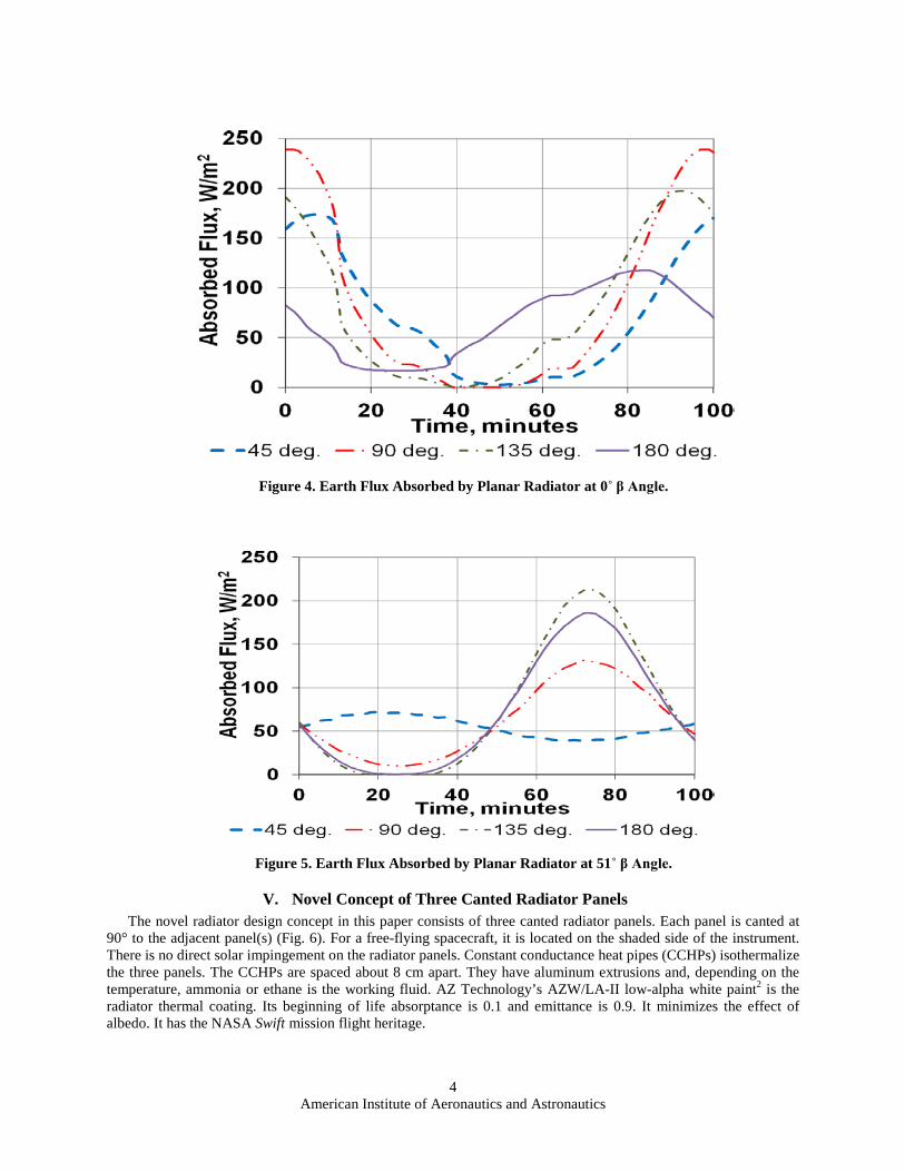
IV. Planar Radiator Thermal Issue The thermal issue of a planar radiator for cooling an instrument on a slewing free-flying spacecraft or slewing
payload on the ISS is presented first. The radiator coating is assumed to be AZ93 white paint which has a 0.16 absorptance and a 0.9 emittance. From Fig. 4, at a 0˚ β, the Earth flux absorbed by the radiator increases by as much as 240 W/m2 from (0 to 240 W/m2) in the same orbit. Also from this figure, if the spacecraft slews from 180˚ to 90˚ sun angle, the Earth flux absorbed by the radiator increases by as much as 170 W/m2 (from 70 to 240 W/m2). From Fig. 5, at a 51˚ β, the Earth flux absorbed by the radiator increases by as much as 220 W/m2 from (0 to 220 W/m2) in the same orbit. Also from this figure, if the spacecraft slews from 45˚ to 135˚ sun angle, the Earth flux absorbed by the radiator increases by as much as 180 W/m2 (from 40 to 220 W/m2). Note that as Earth flux increases, the view factor from the radiator to Earth increases and that from the radiator to space decreases. It causes the radiator temperature to increase.
American Institute of Aeronautics and Astronautics
4
Figure 4. Earth Flux Absorbed by Planar Radiator at 0˚ β Angle.
Figure 5. Earth Flux Absorbed by Planar Radiator at 51˚ β Angle.
V. Novel Concept of Three Canted Radiator Panels The novel radiator design concept in this paper consists of three canted radiator panels. Each panel is canted at
90° to the adjacent panel(s) (Fig. 6). For a free-flying spacecraft, it is located on the shaded side of the instrument. There is no direct solar impingement on the radiator panels. Constant conductance heat pipes (CCHPs) isothermalize the three panels. The CCHPs are spaced about 8 cm apart. They have aluminum extrusions and, depending on the temperature, ammonia or ethane is the working fluid. AZ Technology’s AZW/LA-II low-alpha white paint2 is the radiator thermal coating. Its beginning of life absorptance is 0.1 and emittance is 0.9. It minimizes the effect of albedo. It has the NASA Swift mission flight heritage.

American Institute of Aeronautics and Astronautics
5
As the spacecraft slews, at least one of the three radiator panels has a good view factor to space (Fig. 7 and Fig. 8). The three canted panel design ensures that the overall radiator view factor to space is sufficient all the time throughout the mission.
Figure 6. Three Canted Radiator Panels on a Notional Spacecraft.
Figure 7. Three Canted Radiator Panels in Orbit, 0˚β and 90˚ Sun Angle.
Panel #1
Panel #2
Panel #3
Spacecraft (Notional)
Instrument (Notional)
Canted Radiator Panels

American Institute of Aeronautics and Astronautics
6
Figure 8. Three Canted Radiator Panels in Orbit, 51˚β and 90˚ Sun Angle.
VI. Earth Flux Absorbed by Three Canted Radiator Panels in Orbit The three canted radiator panels are isothermalized by CCHPs. The temperature is dependent on the Earth flux absorbed, waste heat to be rejected and view factor of radiator panels to space. Figures 9 through 12 show the Earth flux absorbed by each panel as a function of sun angle in orbit for a 51˚ β angle, which is the maximum, case. The average Earth flux absorbed by the three panels is also shown. The sun angle is the angle between the solar vector and optical axis of the instrument. It is typically in the 45˚ to 180˚ range. The 45˚ constraint is to prevent sunlight from entering the telescopes. As the Earth flux absorbed increases, the view factor of the radiator panel to Earth increases and view factor of the radiator panel to space decreases. It causes the radiator temperature to increase. From Fig. 9, for a 45˚ sun angle, the average Earth flux absorbed by the three panels is about the same as that absorbed by panel #2. The three panel approach has no thermal advantage over panel #2 alone. As the spacecraft slews, the sun angle changes. From Fig. 10 through Fig. 12, the average Earth flux absorbed by the three panels, peak or valley, is significantly smaller than that absorbed by panel #1, #2 or #3 alone. Hence the three panel approach has a significant thermal advantage. It improves the peak and valley temperatures and provides better thermal stability. It could prevent the instrument detectors from overheating. This is also true for other β angles.
Canted Radiator Panels

American Institute of Aeronautics and Astronautics
7
Figure 9. Earth Flux Absorbed by Radiator at 45˚ Sun Angle and 51˚ β Angle.
Figure 10. Earth Flux Absorbed by Radiator at 90˚ Sun Angle and 51˚ β Angle.

American Institute of Aeronautics and Astronautics
8
Figure 11. Earth Flux Absorbed by Radiator at 135˚ Sun Angle and 51˚ β Angle.
Figure 12. Earth Flux Absorbed by Radiator at 180˚ Sun Angle and 51˚ β Angle.
Figures 13 through 16 show the Earth flux absorbed by each panel as a function of sun angle in orbit for a 0˚ β angle, which is the minimum, case.

American Institute of Aeronautics and Astronautics
9
Figure 13. Earth Flux Absorbed by Radiator at 45˚ Sun Angle and 0˚ β Angle.
Figure 14. Earth Flux Absorbed by Radiator at 90˚ Sun Angle and 0˚ β Angle.

American Institute of Aeronautics and Astronautics
10
Figure 15. Earth Flux Absorbed by Radiator at 135˚ Sun Angle and 0˚ β Angle.
Figure 16. Earth Flux Absorbed by Radiator at 180˚ Sun Angle and 0˚ β Angle.
As the spacecraft slews, the sun angle changes. Figures 17 and 18 show the Earth flux absorbed by the three
canted radiator panels for different sun angles at 0˚ β and 51˚ β respectively. From these figures, when the sun angle

American Institute of Aeronautics and Astronautics
11
changes, the change in Earth flux absorbed is significantly reduced by the three radiator panels concept. It provides better temperature stability.
Figure 17. Average Earth Flux Absorbed by Three Canted Radiator Panels at 0˚ β Angle.
Figure 18. Average Earth Flux Absorbed by Three Canted Radiator Panels at 51˚ β Angle.

American Institute of Aeronautics and Astronautics
12
VII. Slewing Payload on International Space Station The concept of three canted radiator panels is applicable not only to instruments on free-flying spacecraft, but also
to payloads on the ISS ExPRESS Logistics Carriers (ELC). The ISS is in a low Earth orbit with a 340 to 440 km altitude and a 51.6° inclination3. Figures 19 and 20 show the locations of the ELC and ISS in orbit3, respectively. Figure 21 shows the ELC payload envelope4
. A payload is required to be within this envelope in the stowed position. If the payload slews in the science mode, it requires a deployable boom and gimbals (Fig. 22). Thermal radiators could view ISS components, such as solar arrays, when the payload slews. It is possible that solar flux impinges on the payload. Figures 21 and 22 also illustrate the concept of three canted radiator panels for this type of payload. It ensures a view to cold space no matter where solar flux impinges or it views ISS components.
Figure 19. ISS ELC Locations.
Figure 20. Payload Radiators Could View ISS Components.
ELC4
ELC3 ELC2
ELC1

American Institute of Aeronautics and Astronautics
13
Figure 21. ISS ELC Payload Envelope and Concept of Canted Radiator Panels Illustration.
Figure 22. Concept of Canted Radiator Panels for ISS ELC Slewing Payload.
VIII. Conclusion The novel thermal design concept presented in this paper utilizes three radiator panels canted at 90˚ . It has significant advantages over a conventional planar radiator for cooling instruments on free-flying spacecraft or ISS/ELC payloads that slew in LEO. It increases the overall radiator view factor to cold space and reduces the overall solar or albedo flux absorbed per unit area of the radiator. It has good potential applications for astronomy missions. .
Payload within envelope in stowed position. Deployable boom not shown.
Three Canted Radiator Panels
1.245 m
1.168 m
1.245 m
0.864 m
Three Canted Radiator Panels
Boom Deployed Gimbal

American Institute of Aeronautics and Astronautics
14
References 1Choi, M. K., “Maintaining Swift XRT CCD at -50ºC or Colder After TEC Power Supply Failure,” 3rd International Energy
Conversion Engineering Conf. Proceedings, San Francisco, CA, 15-18 Aug., 2005, Paper Number: AIAA-2005-5588. 2 AZ Technology, Inc., ”Spacecraft Thermal Control and Conductive Paints/Coatings and Services Catalog”, Effective
January 2008, Huntsville, AL, p. DS-2a and p. DS-2b. 3Croonquist, A., “International Space Station: Summary of Platform Specifications”, Nov. 12, 2009, KISS Exoplanet
Workshop, JPL/Caltech, Pasadena, CA. 4
NASA. (2008, August), “Attached Payload Interface Requirements Document – Expedite the PRocessing of Experiments to Space Station (EXPRESS) Logistics Carrier (ELC) Cargo Interface Requirements”, Houston, Texas, United States of America.