thomas jefferson national accelerator facility page 1 ipr october 18-20 - 2011 independent project...
TRANSCRIPT

Thomas Jefferson National Accelerator Facility
Page 1
IPR October 18-20 - 2011
Independent Project Review of 12 GeV Upgrade Jefferson Lab
October 18-20, 2011
SVT Mechanical Design at JLAB
Saptarshi Mandal
Thomas Jefferson National Accelerator Facility
Page 2
IPR October 18-20 - 2011
Outline
• Overview of mechanical aspects of Barrel Silicon Tracker (BST)
• Discussion of mechanical and thermal design• Assembly of the detector• Quality Assurance of the detector• Summary

Thomas Jefferson National Accelerator Facility
Page 3
IPR October 18-20 - 2011
Central Tracker
CTOF
Solenoid
SVT
SVT Support and Alignment System

Thomas Jefferson National Accelerator Facility
Page 4
IPR October 18-20 - 2011
Features of BST
• Four region barrel• Region 1: 10 modules; Region 2: 14 modules; • Region 3: 18 modules; Region 4: 24 modules
• Acceptance 35o – 125o
• Operating Temperature 20o – 25oC
• Low mass inside acceptance region
Thomas Jefferson National Accelerator Facility
Page 5
IPR October 18-20 - 2011
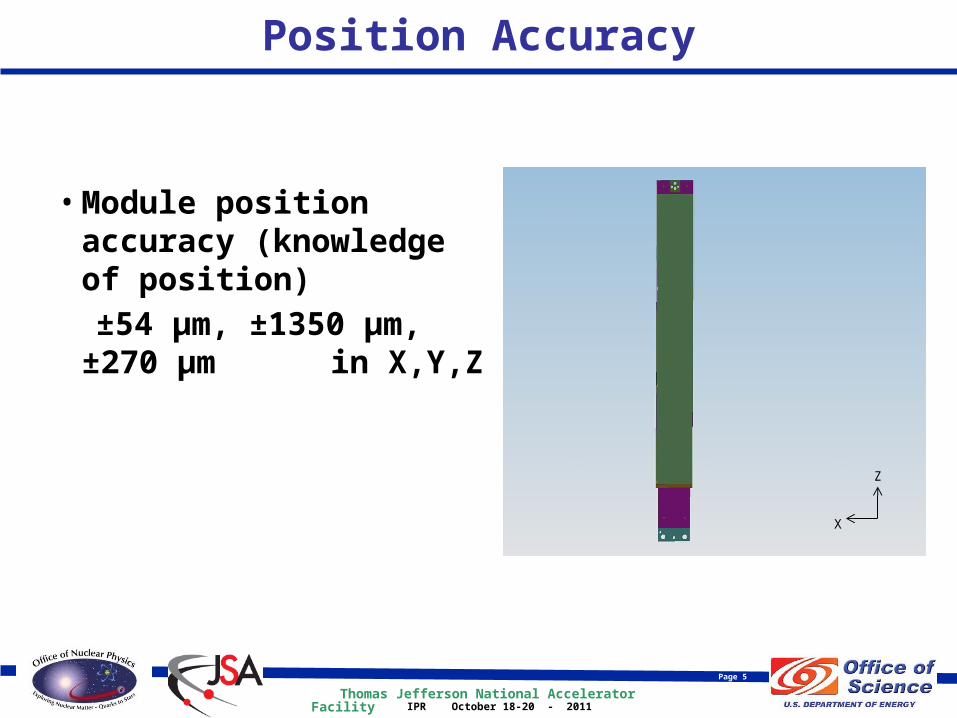
Position Accuracy
• Module position accuracy (knowledge of position)
±54 µm, ±1350 µm, ±270 µm in X,Y,Z
X
Z
Z
X
Thomas Jefferson National Accelerator Facility
Page 6
IPR October 18-20 - 2011
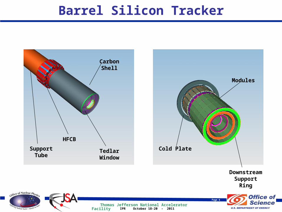
Barrel Silicon Tracker
Downstream Support
Ring
HFCB
Support Tube
Tedlar Window
Carbon Shell
Cold Plate
Modules
Thomas Jefferson National Accelerator Facility
Page 7
IPR October 18-20 - 2011
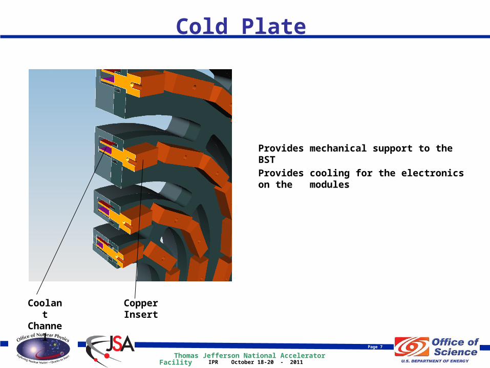
Cold Plate
Provides mechanical support to the BST
Provides cooling for the electronics on the modules
Copper Insert
Coolant Channel

Thomas Jefferson National Accelerator Facility
Page 8
IPR October 18-20 - 2011
Cold Plate and Support Rings
Downstream Support
Ring
Upstream Support
Ring
Module
Module is supported between upstream and downstream support rings
Module is positioned by accurately machined pin holes in the two rings and the stave
(Region 3 shown)
Cold Plate

Thomas Jefferson National Accelerator Facility
Page 9
IPR October 18-20 - 2011
BST Section View
Coolant Channel
Stave Support & Conductor
Module
Upstream Support
Ring
Insert
Thomas Jefferson National Accelerator Facility
Page 10
IPR October 18-20 - 2011
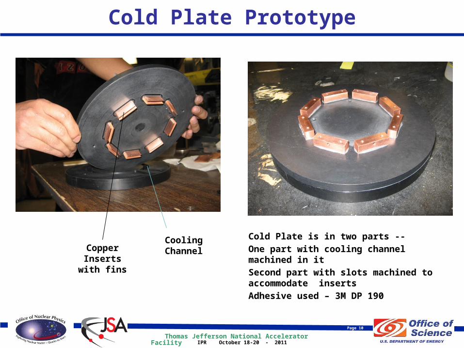
Cold Plate Prototype
Copper Inserts with fins
Cooling Channel
Cold Plate is in two parts --
One part with cooling channel machined in it
Second part with slots machined to accommodate inserts
Adhesive used – 3M DP 190
Thomas Jefferson National Accelerator Facility
Page 11
IPR October 18-20 - 2011
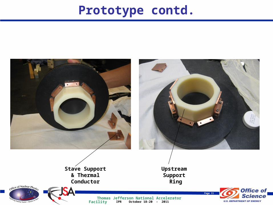
Prototype contd.
Upstream Support
Ring
Stave Support & Thermal
Conductor
Thomas Jefferson National Accelerator Facility
Page 12
IPR October 18-20 - 2011
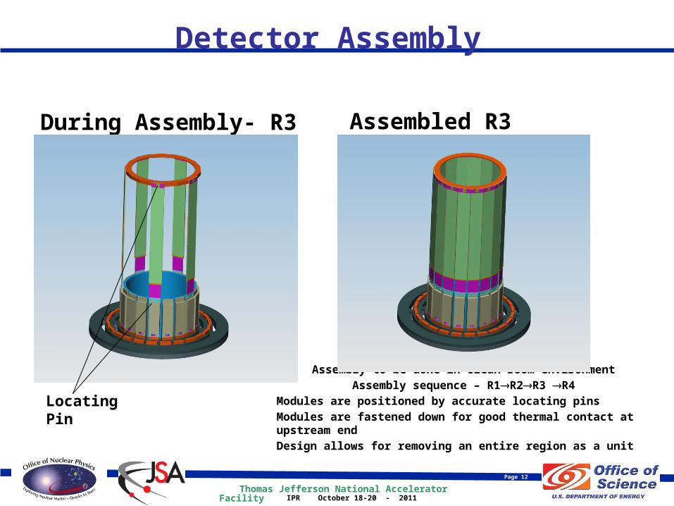
Detector Assembly
During Assembly- R3 Assembled R3
Locating PinAssembly to be done in clean room environment
Assembly sequence – R1R2R3 R4
Modules are positioned by accurate locating pins
Modules are fastened down for good thermal contact at upstream end
Design allows for removing an entire region as a unit

Thomas Jefferson National Accelerator Facility
Page 13
IPR October 18-20 - 2011
Module
Functions• Mechanical support and positioning
of sensors and electronics
• Cooling of ASICs
Features• Carbon skin (.250 mm) with Rohacell
71 core (2.5 mm)
• Rohacell 71 core replaced by copper core (2.5 mm) under electronics
• Kapton bus cable used for grounding on top and bottom surface
Fastening Hole
Hole for Locating Pin
Slot for Locating
Pin
Sensors
Bus Cable

Thomas Jefferson National Accelerator Facility
Page 14
IPR October 18-20 - 2011
Module Close-up View
Rohacell 71
Pitch Adapter
Copper Heat Sink
ASIC
Carbon Fiber
Silicon Sensor
Thomas Jefferson National Accelerator Facility
Page 15
IPR October 18-20 - 2011
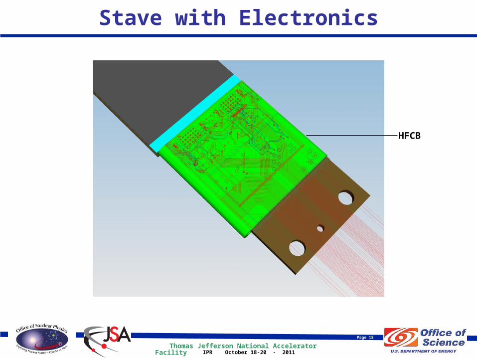
Stave with Electronics
HFCB
Thomas Jefferson National Accelerator Facility
Page 16
IPR October 18-20 - 2011
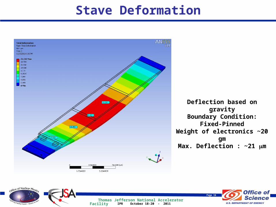
Stave Deformation
Deflection based on gravityBoundary Condition: Fixed-
PinnedWeight of electronics ~20 gm
Max. Deflection : ~21 m
Thomas Jefferson National Accelerator Facility
Page 17
IPR October 18-20 - 2011
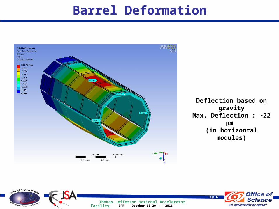
Barrel Deformation
Deflection based on gravity
Max. Deflection : ~22 m (in horizontal modules)

Thomas Jefferson National Accelerator Facility
Page 18
IPR October 18-20 - 2011
Stave Temperature Distribution
Heat Input : 3W (Expected input ~2W)
Coolant: WaterCoolant temperature: 15oC
Nitrogen Purge at 20oCHeat Sink Material : Copper
Peak Temperature : 23oC

Thomas Jefferson National Accelerator Facility
Page 19
IPR October 18-20 - 2011
Highlights of Quality Assurance Plan
• Visual inspection of each module
• Dimensional accuracy check of modules using CMM to ensure compliance with engineering drawings
• Dimensional accuracy check of cold plate and all thermal and structural components to ensure that they meet drawing specifications
• First article tests of mechanical and thermal components to check engineering design
• Position of each module measured and recorded during assembly to provide accurate knowledge of position of each module

Thomas Jefferson National Accelerator Facility
Page 20
IPR October 18-20 - 2011
Summary
• FEA showed deflections and temperature to be within acceptable range
• Prototype of the cold plate demonstrated the feasibility of the cooling method to be used
• Quality Assurance plan is well developed