thomas bmt spin or algebra - digital library/67531/metadc718332/m2/1/high... · spin or algebra...
TRANSCRIPT

Editors: M. Tigner, Cornel1 A. Chao, SLAC
Publisher: World Scientific
BNL 66455 April 19,1999
Sections written by Thomas Roser, BNL:
2.7.1 - Thomas - BMT equation 2.2.2 - Spin or Algebra 2.7.3 - Spin Rotators and Siberian Snakes 2.7.4 - Ring with Spin Rotator and Siberian Snakes 2.7.5 - Depolarizing Resonances and Spin Flippers
7.6.2 - Proton Beam Polarimeters &
DISCLAIMER
This report was prepared as an account of work sponsored by an agency of the United States Government. Neither t he United States Government nor any agency thereof, nor any of their employees, make any warranty, express or implied, or assumes any legal liability or responsibility for the accuracy, completeness, or usefulness of any information, apparatus, product, or process disclosed, or represents tha t its use would not infringe privately owned rights. Reference herein to any specific commercial product, process, or service by trade name, trademark, manufacturer, or otherwise does not necessarily constitute or imply its endorsement, recommendation, or favoring by the United States Government or any agency thereof. The views and opinions of authors expressed herein do not necessarily state or reflect those of the United States Government or any agency thereof.

DISCLAIMER
Portions of this document may be illegible in electronic image products. Images are produced from the best available original document.

I
e p p d 3He
introducing a large number of background beam- ion events, No indirect beam-beam compensation scheme has moved beyond the conceptual stage, to date.
G 0.00115965 0.440649 0.680342 0.00116592 90.6220 0.00330816 1.79285 0523341 0.572843 -0.142562 13.1522 9.0227940 4.19144 0.669910 0.895023
Betatron phase cancelation A single set of beam-beam resonances may be eliminated by ad- justing the phase advance between neighboring IPS in a storage ring [18]. For example, if t5e phase advance between two Ips is A& = A& = 2n(p/N + q) (p, q, N integers, p odd), then all beam-beam resonances of order N are canceled. This scheme, which has not been fried in practice, relies on the collision points being clustered - not smoothly distributed around the circumference. Other resonances, tune shifts, and tune spreads are left uncompensated.
3H I 7.93689
References
0353779 0.847401 I
YK Batygin, T. Katayama, RTKEN-AF-AC-3, 1997 JE. Augustin et al, p.113, Vol. 2, Proc. 7th Int. Conf. H. E. Acc. (1969) G. Arzelia et a$ p.150, Roc. 8th Int. Conf. H. E. Acc. (1971) H. Zyngier, AD? Proc. 57 (1979) p.136 YaS. Derbenev, 3rd All Union Conf. on Acc. (1972); INP 70-72 (1972); SLAC TRANS 151 (1973) . E. Keil, Proc. 3rd ICFA Beam Dyn. Wkshp.
Orsay SR Group, EEE Trans. Nucl. Sci. NS-26, No.3 (1979) 3559 R. Chehab et al, Proc. 1 lth Int. Conf. High Energy Acc. (1980) VE. Balakin, NA. Solyak, Proc 13th Int. Conf. High Energy ACC. (1986)
(1989); ERN-LEI?-lW89-37 (1989)
[lo] N Soly&-INP 884, Novosibirsk (1988) [ 1 13 D. Whittum, R. Siemann, PAC 97
1131 JB. Rosenzweig et al, hoc. Lake Arrowhead Wkshp., AD? Press (1989) p.324
1141 R. Talman, unpublished (1976) [15j E. Tsyganov et al, SSCL-519, (1993); JINR-Eg-
[16] V. Shiltsev, D. Finley, FERMILAB-TM-2008
[17J D. Whittum et al, LBL-25759 (1988) [18] S. Peggs, Proc. Wkshp. on AP Issues for SSC,
1121 Y. Chin, DESY 87-011 (1987)
964, Dubna (1996)
(1997)
UM HE 84-1 (1984) p.58
Handbook of Accelera tor Physics and Engineering By A. Chao (SLAC) ; M. Tigner (Cornell) . World Scient i f ic , sections(2.7.1-2.7.5 and 7.6,2
BNL- 6 6 4 5 5 2.7 POLARIZATION
2.7.1 Thomas-BMT equation
Precession of polarization vector F of a particle with mass m and charge Ze [l, 2,3,4],
Z Roser; BNL
P‘ is defined in the particle rest ftame, 2 and B in the laboratory *e. B’ = 2-1- + Bll, Zil =
In the ftame rotating with v’ given by the (v’. B)v’/v2.
Lorentz force equation and assume Ell = 0, - dv’ = d,xa at
dp d t - = f ixp’
G = 9 is the anomalous magnetic moment; g = 25 is the pqyrom~etic ratio (Landau fac-
102

References
[l] B.W.Montague, Phys. Rep. 113 (1984) 1 [2] L.H. Thomas, Phil. Mag. 3 (1927) 1 [3] V. Bargmann, L. Michel, V.L. Telegdi, PRL 2
[4] S.Y. Lee, World Scientific (1996) (1 959) 435
2.7.2 Spinor Algebra 2: Rose< BNL
Coordinate frame symbols and indices: (1,2,3) =(radial outward, longitudinal forward, vertical up) = (2, -5, 9). Pauli matrices: a' = (61, a2, a3)
0 1 1 0 =[( 1 O)'( 8 ii)( 0 -1)]
( T 1 q = a2a2 =a3a3 = I (1) ~ 3 ~ 1 = -0103=ia2 (cyclic perm.) (2)
tr(ai) = 0, det(ai) = -1 (3)
(4)
Spinor representation of normalized vector F: ($4) ($4) = (iq +iz. (zxc)
F = ?pa$
Thomas-BMT equation in spinor or unitary repre- sentation:
- = f i x F d p dt
d t 2 or
solution for constant fi : xis A, 161 = w): ,$ ( t ) = M (% 4 ,$ (0) 3 or (7)
(a - P (t)) = M ( ~ , w t ) (a - F(0)) Mt ( f i ,wt)
Rotation operation M by angle cp = w t around axis n
M(fi,cp) = exp - i ($- . iz) - [ 'I 2
- - cos (i) - i (Z - ii) sin (g) Inverse operation:
A tr ($Ad) i 2 sin (3) n =
. (9)
One-turn matrix Mo (0) :
where 8 is the starting (and ending) azimuth. The spin tune uw and the spin closed orbit f i ~ (also called A0 axis or stable spin direction) are
(12)
Mo (e) = M,: - - M2M1 (1 1)
1 cos (7rvw) = -tr 2 (Mo (e))
independent of 8
2.73 Spin Rotators and Siberian Snakes iT Rosel; BNL
"Spin Rotators" rotate P' without changing G. Examples of Spin Rotators:
1.
2.
3.
4.
Wien Filter: Transverse E,, B, with condi- E x i 7 - 1- B' tion - $ I Y
cp cp Mwien = COS - - ia3 sin - 2 2 Solenoid
J ~ i i d s Ze(l+G)
mcPY c p =
cp cp 2 2 kf&le.oid = cos - - 202 sin - (2)
Example: cp = 90" and p = 1 GeV/c re- quires J BIIds = 1.88 T-m for protons and J BIIds = 5.23 T-m for elecuons.
Dipole:
cp cp cos - - io3 sin - 2 2 (3)
Example: cp = 90" and /3 x 1 re- quires J Byds = 2.74 T-m for protons and J Byds = 2.31 T-m for electrons.
MDipole =
Full twist helical dipole with B ( s ) = BO ( s iny ,O ,cosT) , A > s > 0:
cp cp cos - - i(a2 + xa3) sin - 2 2 M =
ZeG BOX G r mc 27r
(4)
x = ( 1+- ' ) -- 103
5. A "Full Siberian Snake" rotates P' by 180" (9 = n) around an axis in the horizontal plane with angle Q fkom 2 (Snake axis an- gle) Ill:
5. Ring with N pairs of full Siberian snakes with axis angles or; and or; at 0; and g6:
Mo(8) = (-)NexP(-ic3x) (5) N
M s n & = -i (a1 cos + a2 sin or) (5) x = c(or;-a:) i=l
N
i=l
Note:
(ii) Type 1 snake: snake axis is longitudinal (or =
(iii) Type 2 snake: snake axis is radial (or = 0")
(i) MDipoleMSnakeMDipole = MSnake-
goo)
References
Note: MO is energy independent for CE,($-Q = n; then usp = 6 EEl (or; - or:).
[l] YaS. Derbenev, A.M. Kondratenko, PA 8 (1978)
References 115
2*704 Ring With Spin and Siberian [l] T. Roser, ROC. Workshop on Siberian Snakes and Depolarizing Techniques (1989) p.1442 Snakes
T. Rose< BNL
1.
2.
3.
4.
Ideal ring without spin rotators or Siberian snakes:
MO (8) = exp (-iu3nG~) (1) Note: usp = G7.
Ring with solenoid (partial type 1 Siberian snake) at 80 = 0 [ 11:
cp 2
M~ (e) = cos - COS ( X G ~ )
cp 2 cp 2 cp 2
- iul sin - sin ((n - 8) G7)
- iu2 sin - cos ((n - 8) G7)
- iu3 cos - sin (nG7) (2)
Note: cos(nv,) = cos 5 cos (nGy).
Ring with full Siberian snake with axis angle a at 00 = 0: MO (0) = --i[01 COS(CY - (T - 0)GT)
+ 02 sin(a! - (n - 8)Gn/)] (3) for all 8; 8 = n -+ .720 = Note: usp =
ri.cosa$Bsina Ring with two full Siberian snakes with axis angles CY, and ab at Bu and 8b :
Mo (8) = -exp(-iu3x) (4) x E - 4- (n - 66 4- &)G7
Note: MO is energy independent for Ob - 8, = n; then usp = ;; (ab - cra). 1
2.7.5 Depolarizing Resonances and Spin Flippers I: Roser, BNL
Thomas-BMT equation with azimuthal coordi- nate 8 as independent variable and the fields ex- pressed in terms of the particle coordinates:
(1 + G7)g' - p ( 1 + G)
where p is bending radius. Resonance strength is
(2)
K = kP =t uy : intrinsic resonance from vertical betatron motion, P is the super periodicity K = k : imperfection resonance from vertical closed orbit distortions.
= EK exp (iK8). In frame rotating around jj with tune K ,
111 EK = - f t e x p (-iK8) d6
2n
For isolated resonance:
+K = exp ($m3)11,
Under adiabatic conditions: (G7 - K) PY =
2 d(G7 - Kl2 + ~ K I (4)
104

Passage through an isolated resonance, Froissart- Stora Equation [2]:
n IEKI -- Pfinal - 2exp (-<) - 1 (5) Enitial
4 G Y ) with CY = dB (crossing speed). Fast passage -+ Pfinal M Pinitiai. Slow passage -+ Pfinal M
-Pinitial 4 spin flip. . Artificial resonance from local oscillating field (w = applied frequency, wo = revolution frequency):
BII = S l l C O S ( W t )
(7) Spin flip by ramping artificial resonance through resonance condition with speed CY:
(8) Kend - Kstart
2nN C Y =
where N is number of turns during ramp. For more than 99% spin flip:
III a ring with Snakes (vsp = 4) additional higher order 'Snake' resonances [3] occur at ener- gies close to intrinsic resonances of the ring with- out Snakes when the fractional vertical betatron tune
2k - 1 AvY = 2(21- 1)
With vertical closed orbit distortions Snake reso- nances also occur when
References
[l) ED. Courant, R. Ruth, BNL-51270 (1980) [2] M. Froissart, R. Stora, NIM 7 (1960) 297 [3] S.Y. Lee, S . Tepikian, PRL 56 (1986) 1635
2.7.6 Polarized Proton Beams and Siberian Snakes A. D. Krisch, U. Michigan
In 1973, the first polarized proton beam was suc- cessfully accelerated in the Argonne ZGS. The
depolarizing resonances were not too strong in the weak focusing ZGS; thus it only required care- ful orbit control and fast betatron tune jumps to maintain the polarization while crossing the reso- nances [l].
on Source
Linac
\2GQ MeV c Pohrmler
Figure 1: The complex individual depolarizing reso- nance correction hardware installed in the AGS [21.
In 1984, polarized protons were first acceler- ated at the Brookhaven AGS. Maintaining the po- larization was much more difficult, because the strong-focusing AGS has strong depolarizing res- onances. As shown in Rg.1, the AGS required complex hardware modifications for this difficult job. Moreover, 45 resonances needed to be cor- rected individually to maintain the polarization up to 22 GeV. A typical AGS resonance correction curve is shown in Fig2 [Z]. The polarized beam tune-up required 7 weeks of dedicated AGS oper- ation. Clearly this individual resonance correction technique was impractical for a much higher en- ergy, since the number of imperfection resonances to be crossed is E / (0.52 GeV). Thus, it became clear [3] that Siberian snakes (41 (Sec.2.7.34) were needed to accelerate polarized protons above 30 GeV.
Many Siberian snake experiments have been performed at the 500-MeV IUCF Cooler Ring. The snake was a 2 T-m superconducting solenoid installed in a 6-m straight section, as shown in
105

Dr. T. Roser AGS Dept Broohaven National Lab Upton, NY 11973-5000
May 16,1998
Dear Dr. Roser,
Enclosed you will find type set proofs of your article for the Handbook of Accelerator Physics and Engineering for your correction before final editing and publication. Even though time is very short, it is being sent to you by post so that you can see, with good resolution, how it will appear in the book.
While the type setting process is largely automated, some needed format changes and equations require human intervention, thereby creating opportunity for errors. For this reason it is extremely important for you to check every aspect PARTICULARLY EQUATIONS AND REFERENCES.
Please mark the corrections clearly and fax them back to me at 607 254 4552 as soon as possible. If you are unable to do it immediately, please note that it will be very difficult to include any corrections received after July 15 so if we have not heard from you by then we will assume that you have no corrections to submit.
Your expert and patient participation in this enterprise is very deeply appreciated indeed and we hope that you will have your copy of the finished book in hand early in 1999.
I ?
(max for 90" scattering):
(7 + cos2 8') sin2 8' 7 I 9 (22) All = (3 + cos2 8/12
The polarized electron targets in Moller po- larimeters typically consist of thin ferromagnetic foils exposed to a - 100 gauss external magnetic field oriented with a given angle to the foil axis. A 8.3% maximum polarization of the target elec- trons (2 external out of 26 electrons per iron atom) has been achieved. The target polarization is mea- sured to 1.5 - 2.0% precision (1.7% at SLAC).
The full beam polarization vector is deter- mined by varying the foil orientation relative to the beam.
The analyzing power of Mraller polarimeters need corrections due to orbital motion of inner shell target electrons [ 141 (momenta comparable to e* rest mass).
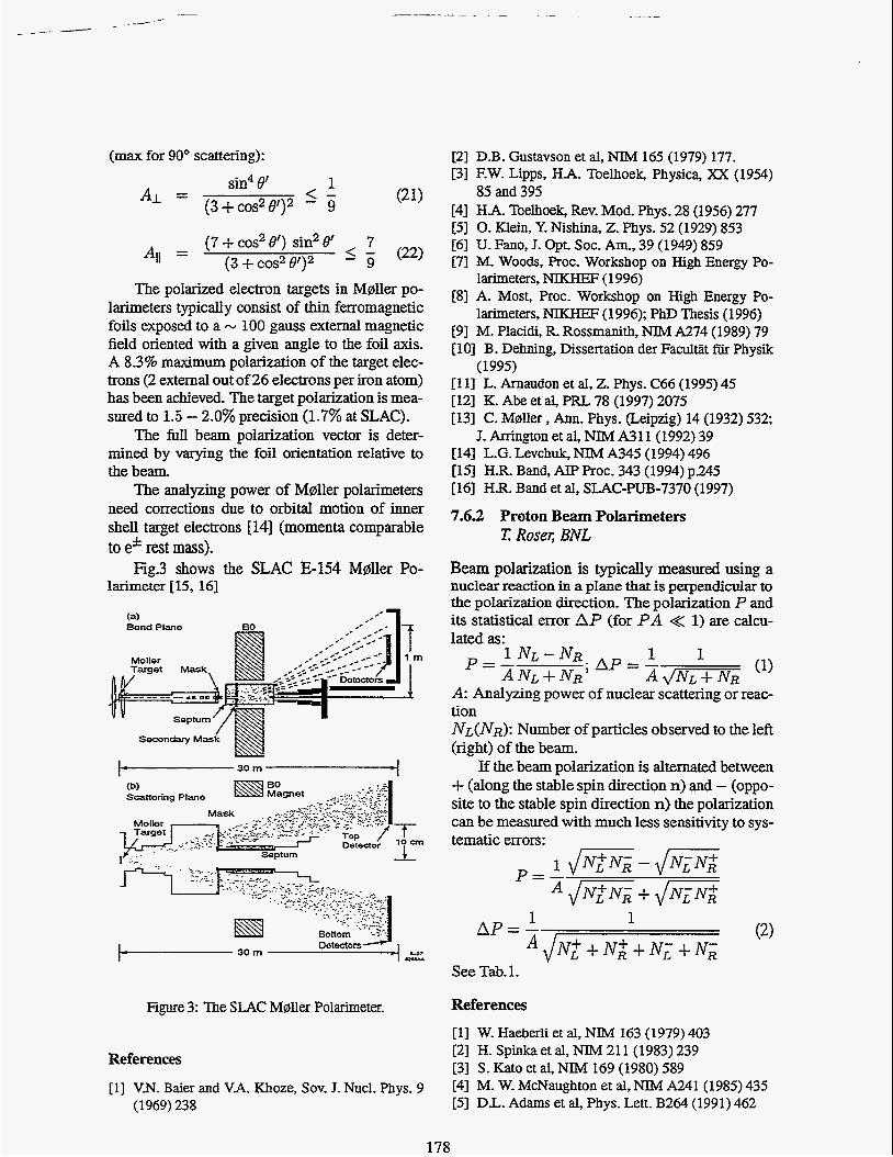
Fig3 shows the SLAC E-154 Mdler Po- larimeter [U, 161
Bend Plane
Moller Target Mask, . . ,
Secondary Mask
v v
Scattering Plane
Figure 3: The SLAC M0ller Polarimeter.
References
[l] VN. Baier and V.A. Khoze, Sov. J. Nucl. Phys. 9 (1969) 238
[2] DB. Gustavson et al, NIM 165 (1979) 177. [3] F.W. Lipps, HA. Toelhoek, Physica, XX (1954)
[4] HA. Toelhoek, Rev. Mod. Phys. 28 (1956) 277 [5] 0. Klein, Y. Nishina, Z . Phys. 52 (1929) 853 [6] U. Fano, J. Opt. SOC. Am., 39 (1949) 859 171 M. Woods, Proc. Workshop on High Energy Po-
[8] A. Most, Proc. Workshop on High Energy Po-
[9] M. Placidi, R. Rossmanith, NIM A274 (1989) 79 [ 103 B . Dehning, Dissertation der Facultiit fijr Physik
[I 13 L. Arnaudon et al, Z . Phys. C66 (1995) 45 [12] K. Abe et al, PRL 78 (1997) 2075 [13] C. Maller , Ann. Phys. (Leipzig) 14 (1932) 532;
J. Arrington et al, NIM A3 1 1 (1992) 39 [14] L.G. Levchuk, NTM A345 (1994) 496 [15] HR. Band, AIP Proc. 343 (1994) p245 [ 161 H.R. Band et al, SLAC-PUB-7370 (1997)
7.63 Proton Beam Polarimeters
85 and 395
larimeters, NIKHEF (1996)
larimeters, NIKHEF ( 1996); PhD Thesis (1 996)
(1 995)
T Roser; BNL
Beam polarization is typically measured using a nuclear reaction in a plane that is perpendicular to the polarization direction. The polarization P and its statistical error A P (for P A << 1) are calcu- lated as:
A: Analyzing power of nuclear scattering or reac- tion NL(NR): Number of particles observed to the left (right) of the beam.
If the beam polarization is alternated between + (along the stable spin direction n) and - (oppo- site to the stable spin direction n) the polarization can be measured with much less sensitivity to sys- tematic errors:
"drvL+ + NR+ + N ; + N; See Tab. 1.
References [l] W. Haeberli et al, NIM 163 (1979) 403 [2] H. Spinka et al, NIM 21 1 (1983) 239 [3] S. Kat0 et al, NIM 169 (1980) 589 [4] M. W. McNaughton et al, NIM A241 (1985) 435 [5] DL. Adams et al, Phys. Lett. B264 (1991) 462
178
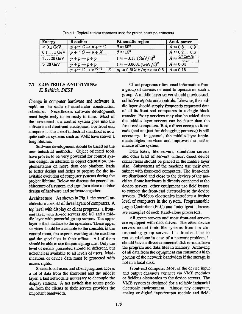
Table 1: Typical nuclear reactions used for proton beam polarimeters.
Energy Reaction < 0.1 GeV p+” C - ) p +12 C 0.1.. .1 GeV p+’” C + p + X
>2OGeV p + p + p + p 1.. .20 GeV p + p + p + p
ZI +12 C + T+(-) + X
Kinematic region Anal. power 6 x 50’ A = 0.8. . -0.9 6 x 15” A x 0.2. . .0.6
t = -0.0001 (GeV/c)2 A x 0.04 vt 0.5GeV/c:x~ x 0.5 A x 0.15
t = -0.15 (GeV/c)2 A 0.7GeV/c PT,ah
7.7 CONTROLS AND TIMING K. Rehlich, DESY
Change in computer hardware and software is rapid on the scale of accelerator construction schedules. Nevertheless software development must begin early to be ready in time. Most of the investment in a control system goes into the software and front-end electronics. For front end components the use of industrial standards is now quite safe as systems such as VME have shown a long lifetime.
Software development should be based on the new industrial methods. Object oriented tools have proven to be very powerN for control sys- tem design. In addition to object orientation, im- plementation on more than one platform leads to better design and helps to prepare for the in- evitable evolution of computer systems during the project lifetime. Below we discuss the general ar- chitecture of a system and argu for a clear modular design of hardware and software together. Architecture As shown in Fig.1, the overall ar- chitecture consists of three layers of computers. A top level with display or client programs, a fi-ont- end layer with device servers and UO and a mid- dle layer with powerful group servers. The upper layer is the interface to the operators. These upper services should be available to the consoles in the control room, the experts working at the machine and the specialists in their offices. All of them should be able to use the same programs. Only the level of det‘ails presented should be different, but nonetheless available to all levels of users. Mod- ifications of device data must be protected with access rights.
Since a lot of users and client programs access a lot of data from the front-end and the middle layer, a fast network is necessary to decouple the display stations. A net switch that routes pack- ets from the clients to their servers provides the important bandwidth.
Client programs often need information from a group of devices or need to operate on such a group. A middle layer server should provide such collective reports and controls. Likewise, the mid- dle layer should supply frequently requested data of all its front-end computers in a single block transfer. Proxy services may also be added since the middle layer servers can be faster than the front-end computers. But, a direct access to front- ends (and not just for debugging purposes) is still necessary. In general, the middle layer imple- ments higher services and improves the perfor- mance of the system.
Data bases, file servers, simulation servers and other kind of servers without direct device connections should be placed in the middle layer also. Subsystems of the machine use their own subnet with front-end computers. The front-ends are distriiuted and close to the devices of the ma- chine. Some hardware is directly connected to the device servers, other equipment use field busses to connect the front-end electronics to the device servers. Fieldbus electronics introduce a further level of computers in the system. Programmable Logic Controller (PLC) and “intelligent” devices are examples of such stand-alone processors.
All group servers and most fi-ont-end servers are equipped with disk drives. The other device servers mount their Ne systems from the cor- responding group server. If a front-end has to run stand-alone in case of a network problem, it should have a direct connected disk or must have the program and data files in memory. Archiving of all data fiom the equipment can consume a high portion of the network bandwidth if the storage is not in a local disk.
Front-end computer Most of the device input and output channels connect via VME modules or fieldbus electronics to the device servers. The VME system is designed for a reliable industrial electronic environment. Almost any computer, analog or digital input/output module and field-
179