this page left intentionally blank - navy bmrnavybmr.com/study material/navsea op 3565.pdf ·...
TRANSCRIPT

This page left intentionally blank

NAVSEA OP 3565/NAVAIR 16-1-529 VOLUME 2
SEVENTEENTH REVISION
TECHNICAL MANUAL
ELECTROMAGNETIC RADIATION HAZARDS (U)(HAZARDS TO ORDNANCE) (U)
DISTRIBUTION STATEMENT AApproved for Public Release; Distribution is Unlimited.
THIS PUBLICATION SUPERSEDES NAVSEA OP 3565/NAVAIR 16-1-529/NAVELEX 0967-LP-624-6010VOLUME 2 SIXTEENTH REVISION DATED 1 JUNE 2007
PUBLISHED BY DIRECTION OF COMMANDER, NAVAL SEA SYSTEMS COMMAND
1 JULY 2008
NAVSEA OP 3565/NAVAIR 16-1-529VOLUME 2 SEVENTEENTH REVISION
A
Reproduction for nonmilitary use of the information or illustrations contained in this publication is not permitted. This does not preclude reproduction and use of any part of this manual by contracted agencies responsible for the training and instruction of personnel who handle and transport military ammunition, explosives, and related hazardous materials. The policy for military use reproduction is established for the Army in AR 380-5, for the Navy and Marine Corps in SECNAVINST 5510.36 (series), and for the Air Force in Air Force Regulations 205-1.
LIST OF EFFECTIVE PAGES
The total number of pages in this manual is 156. They are all original Revision Seventeen pages. The date of issue for all pages in this manual is 1 July 2008.


This page left intentionally blank
Foreword-1/(Foreword-2 Blank)
NAVSEA OP 3565/NAVAIR 16-1-529VOLUME 2 SEVENTEENTH REVISION
FOREWORD
1. The purpose of this volume is to prescribe operating procedures and precautions to prevent initiation of electrically initiated devices (EID’s) in ordnance from electromagnetic radiation (EMR).
2. This manual supersedes NAVSEA OP 3565/NAVAIR 16-1-529 Volume 2 Sixteenth Revision, dated 1 June 2007, which should be destroyed.
3. This volume provides technical guidance to assist commanding officers in carrying out their responsibilities for safety from a radio frequency hazards standpoint. The procedures and precautions prescribed herein apply in every instance within the Naval establishment (ships and shore stations) where an electrically-initiated explosive item is exposed to radio frequency fields of potentially hazardous frequency and intensity. Operational commanders may waive compliance with any provision, when essential, under emergency conditions. When noncompliance with restrictions contained herein is essential, emergency procedures are provided in order to explain and minimize the risks involved.
4. Changes and revisions to this publications will be promulgated by Commanding Officer, Naval Ordnance Safety and Security Activity (NOSSA) in a timely manner following coordination with other cognizant commanders such as NAVAIRSYSCOM for air launched weapons and current aircraft, and SPAWARSYSCOM for transmitter radio frequency (RF) emission data. Interim changes will be made by letter or message as ACN’s (advance change notices) which will be directed to the commanders directly concerned. Comments or suggestions relative to material to be included in such changes should be forwarded as specified in the following paragraph.
5. Ships, training activities, supply points, depots, Naval shipyards, and supervisors of shipbuilding are requested to arrange for the maximum practical use and evaluation of NAVSEA technical manuals. All errors, omissions, discrepancies, and suggestions for improvement to NAVSEA technical manuals shall be reported to the Commander, Naval Surface Warfare Center, Port Hueneme Division (NSWC/PHD) (Code 310), 4363 Missile Way, Port Hueneme, CA 93043-4307 on NAVSEA Technical Manual Deficiency/Evaluation Report (TMDER), NAVSEA Form 4160/1. A copy of NAVSEA TMDER Form 4160/1 is included at the end of this publication. For activities with internet access, this form may also be completed and processed using NSWC/PHD website: https://nsdsa2.phdnswc.navy.mil. To expedite a response, also send as an email to [email protected]. When using this website, the correct publication number to use to generate a TMDER against this manual is OP03565 (4 spaces) 02001700. All feedback comments shall be thoroughly investigated and originators will be advised of TMDER resolution. If you prefer to submit a TMDER using a word file, click here.
TMDER

This page left intentionally blank
NAVSEA OP 3565/NAVAIR 16-1-529VOLUME 2 SEVENTEENTH REVISION
Chapter/Paragraph Page
TABLE OF CONTENTS
List of Figures ..................................................................................................................... iv
List of Tables ...................................................................................................................... v
Safety Summary .................................................................................................................... vi
CHAPTER 1 INTRODUCTION........................................................................................ 1-1
1-1. Purpose ........................................................................................................ 1-11-2. Scope ........................................................................................................... 1-11-3. Background .................................................................................................. 1-31-3.1 The Need for HERO Control. ........................................................................ 1-41-4. Introduction to HERO Classification ............................................................. 1-51-5. Managing HERO .......................................................................................... 1-61-5.1 Assessment of Risk. ..................................................................................... 1-61-5.2 Navy-Unique Classifications. ........................................................................ 1-61-6. Tri-Service Approach to HERO .................................................................... 1-61-6.1 Common Approaches. .................................................................................. 1-71-6.2 DOD-Wide Application. ................................................................................. 1-71-7. Personnel Requirements ............................................................................. 1-71-7.1 Training. ........................................................................................................ 1-71-7.2 Safety Precautions........................................................................................ 1-81-8. HERO Warning Symbols and Labels ........................................................... 1-81-8.1 HERO Warning Symbols. ............................................................................. 1-81-8.2 HERO Warning Labels.................................................................................. 1-81-8.3 Ordering HERO Warning Symbols and Labels........................................... 1-111-9. Definitions, Abbreviations, and Symbols .................................................... 1-111-10. Reference Documents ............................................................................... 1-111-11. Date of Publication ..................................................................................... 1-121-12. HERO Data Sheet Profile Tool .................................................................. 1-12
CHAPTER 2 RF ENVIRONMENTS ................................................................................ 2-1
2-1. Methods for Controlling the RF Environment ............................................... 2-12-1.1 Peak and Average Power Calculations......................................................... 2-12-1.2 Antenna Field Regions.................................................................................. 2-22-1.3 Power Density and Field Intensity Calculations. ........................................... 2-32-2. Field Strength/Distance Restrictions ............................................................ 2-42-2.1 Safe Field Strength/Distance Calculation ..................................................... 2-42-2.2 Relaxation of 10-Foot Rule. .......................................................................... 2-72-2.3 Multiple Superimposed Field Calculations. ................................................... 2-72-3. Control of RF Environments ......................................................................... 2-82-3.1 Control of RF Environments for HERO SUSCEPTIBLE,
HERO UNSAFE, and HERO UNRELIABLE ORDNANCE............................ 2-82-3.2 Notification of Transfer of Other Than HERO SAFE ORDNANCE. .............. 2-8
i
NAVSEA OP 3565/NAVAIR 16-1-529VOLUME 2 SEVENTEENTH REVISION
Chapter/Paragraph Page
TABLE OF CONTENTS (Continued)
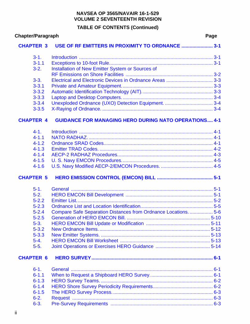
CHAPTER 3 USE OF RF EMITTERS IN PROXIMITY TO ORDNANCE ....................... 3-1
3-1. Introduction .................................................................................................. 3-13-1.1 Exceptions to 10-foot Rule............................................................................ 3-13-2. Installation of New Emitter System or Sources of
RF Emissions on Shore Facilities ................................................................ 3-23-3. Electrical and Electronic Devices in Ordnance Areas .................................. 3-33-3.1 Private and Amateur Equipment................................................................... 3-33-3.2 Automatic Identification Technology (AIT). ................................................... 3-33-3.3 Laptop and Desktop Computers. .................................................................. 3-43-3.4 Unexploded Ordnance (UXO) Detection Equipment. ................................... 3-43-3.5 X-Raying of Ordnance. ................................................................................. 3-4
CHAPTER 4 GUIDANCE FOR MANAGING HERO DURING NATO OPERATIONS.... 4-1
4-1. Introduction .................................................................................................. 4-14-1.1 NATO RADHAZ. ........................................................................................... 4-14-1.2 Ordnance SRAD Codes................................................................................ 4-14-1.3 Emitter TRAD Codes. ................................................................................... 4-24-1.4 AECP-2 RADHAZ Procedures...................................................................... 4-34-1.5 U. S. Navy EMCON Procedures................................................................... 4-54-1.6 U.S. Navy Modified AECP-2/EMCON Procedures. ...................................... 4-5
CHAPTER 5 HERO EMISSION CONTROL (EMCON) BILL ......................................... 5-1
5-1. General ........................................................................................................ 5-15-2. HERO EMCON Bill Development ................................................................ 5-15-2.2 Emitter List.................................................................................................... 5-25-2.3 Ordnance List and Location Identification..................................................... 5-55-2.4 Compare Safe Separation Distances from Ordnance Locations. ................. 5-65-2.5 Generation of HERO EMCON Bill. ............................................................. 5-105-3. HERO EMCON Bill Update or Modification ............................................... 5-115-3.2 New Ordnance Items. ................................................................................. 5-125-3.3 New Emitter Systems. ................................................................................ 5-135-4. HERO EMCON Bill Worksheet .................................................................. 5-135-5. Joint Operations or Exercises HERO Guidance ........................................ 5-14
CHAPTER 6 HERO SURVEY......................................................................................... 6-1
6-1. General ........................................................................................................ 6-16-1.1 When to Request a Shipboard HERO Survey. ............................................. 6-16-1.3 HERO Survey Teams. .................................................................................. 6-26-1.4 HERO Shore Survey Periodicity Requirements............................................ 6-26-1.5 The HERO Survey Process. ......................................................................... 6-36-2. Request ....................................................................................................... 6-36-3. Pre-Survey Requirements ........................................................................... 6-3
ii

NAVSEA OP 3565/NAVAIR 16-1-529VOLUME 2 SEVENTEENTH REVISION
Chapter/Paragraph Page
TABLE OF CONTENTS (Continued)
6-4. Procedures ................................................................................................... 6-96-4.1 Arrival............................................................................................................ 6-96-4.2 Measurement of EME. .................................................................................. 6-96-4.3 Report. .......................................................................................................... 6-96-4.4 Sample HERO Instructions. ........................................................................ 6-10
CHAPTER 7 HERO REQUIREMENTS DURING ORDNANCE OPERATIONS ............. 7-1
7-1. Introduction .................................................................................................. 7-17-2. Ordnance HERO Classifications .................................................................. 7-17-2.1 How to Determine HERO Classification........................................................ 7-17-2.2 How to Use HERO Data. .............................................................................. 7-17-2.3 HERO UNSAFE or HERO UNRELIABLE ORDNANCE. .............................. 7-17-2.4 Components of All-Up Rounds (AUR’S). ...................................................... 7-47-3. General HERO Requirements ..................................................................... 7-47-3.1 General HERO Requirements for Ordnance Operations.............................. 7-57-3.2 HERO Requirements for Transportation of Ordnance on Shore Stations. ... 7-77-3.3 HERO Requirements for Shipboard Ordnance Operations. ......................... 7-8
APPENDIX A DEFINITIONS AND ABBREVIATIONS..................................................... 1-1
A-1. INTRODUCTION ......................................................................................... 1-1A-2. DEFINITIONS .............................................................................................. 1-1A-3. ABBREVIATIONS ........................................................................................ 1-7A-4. SYMBOLS .................................................................................................. 1-21
APPENDIX B REFERENCE DOCUMENTS..................................................................... 2-1
APPENDIX C HERO EMISSION CONTROL BILL WORKSHEETS............................... C-1
APPENDIX D SAMPLE HAZARDS OF ELECTROMAGNETIC RADIATION TOORDNANCE INSTRUCTIONS FOR SHIPS AND SHORE ACTIVITIES................................................................................. D-1
APPENDIX E HERO SURVEY PERIODICITY CHART ...................................................E-1
APPENDIX F THE AIT HERO CERTIFICATION PROCESS ..........................................F-1
iii

NAVSEA OP 3565/NAVAIR 16-1-529VOLUME 2 SEVENTEENTH REVISION
iv
LIST OF FIGURES
FIGURE TITLE PAGE1-1 Guidelines for Using Volume 2 . . . . . . . . . . . . . . . . . . . . . . . . . . . . . . . . . . . . . . . 1-21-2 Example of an EID . . . . . . . . . . . . . . . . . . . . . . . . . . . . . . . . . . . . . . . . . . . . . . . . . 1-31-3 Ordnance Stockpile-to-Safe Separation Sequence . . . . . . . . . . . . . . . . . . . . . . . . 1-51-4 HERO Warning Symbol . . . . . . . . . . . . . . . . . . . . . . . . . . . . . . . . . . . . . . . . . . . . . 1-91-5 HERO Warning Label . . . . . . . . . . . . . . . . . . . . . . . . . . . . . . . . . . . . . . . . . . . . . 1-102-1 Graph and Equations for Computing Safe Field Strength/Distance for
HERO SUSCEPTIBLE ORDNANCE . . . . . . . . . . . . . . . . . . . . . . . . . . . . . . . . . . . 2-52-2 Graph and Equations for Computing Safe Field Strength/Distance for
HERO UNSAFE and HERO UNRELIABLE ORDNANCE . . . . . . . . . . . . . . . . . . . 2-64-1 TRAD Code Numerical Index . . . . . . . . . . . . . . . . . . . . . . . . . . . . . . . . . . . . . . . . . 4-35-1 HERO EMCON Bill Development . . . . . . . . . . . . . . . . . . . . . . . . . . . . . . . . . . . . . 5-35-2 Shipboard HERO EMCON Bill (Sheet 1) . . . . . . . . . . . . . . . . . . . . . . . . . . . . . . . . 5-95-3 Ordnance and Emitter Configuration Changes . . . . . . . . . . . . . . . . . . . . . . . . . . 5-126-1 Checklist for HERO Pre-Survey Data (Sheet 1 of 2) 6-57-1 HERO Classification Guidelines . . . . . . . . . . . . . . . . . . . . . . . . . . . . . . . . . . . . . . 7-37-2 Example of HERO SAFE Distances . . . . . . . . . . . . . . . . . . . . . . . . . . . . . . . . . . . 7-7C-1 Sample Emitter Worksheet . . . . . . . . . . . . . . . . . . . . . . . . . . . . . . . . . . . . . . . . . . C-2C-2 Sample Ordnance Location Worksheet . . . . . . . . . . . . . . . . . . . . . . . . . . . . . . . . . C-3C-3 Sample Emitter Safe Separation Distances versus Distance to
Ordnance Locations . . . . . . . . . . . . . . . . . . . . . . . . . . . . . . . . . . . . . . . . . . . . . . . C-4D-1 Sample Hazards of Electromagnetic Radiation to Ordnance
Instruction for Ships (Sheet 1 of 12) . . . . . . . . . . . . . . . . . . . . . . . . . . . . . . . . . . . . D-2D-2 Sample Hazards of Electromagnetic Radiation to Ordnance
Instruction for Shore Facilities (Sheet 1 of 18) . . . . . . . . . . . . . . . . . . . . . . . . . . . D-14F-1 AIT HERO Certification Process . . . . . . . . . . . . . . . . . . . . . . . . . . . . . . . . . . . . . . F-4F-2 AIT HERO Evaluation Process . . . . . . . . . . . . . . . . . . . . . . . . . . . . . . . . . . . . . . . F-5
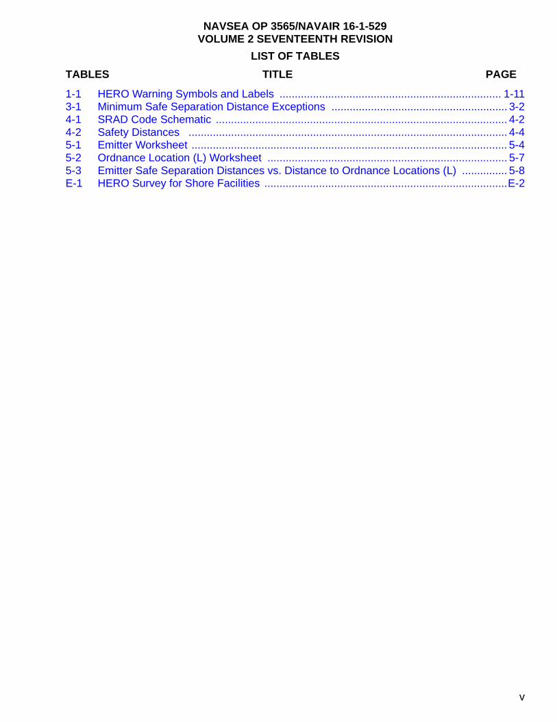
LIST OF TABLES
TABLES TITLE PAGE
v
NAVSEA OP 3565/NAVAIR 16-1-529VOLUME 2 SEVENTEENTH REVISION
1-1 HERO Warning Symbols and Labels ......................................................................... 1-113-1 Minimum Safe Separation Distance Exceptions .......................................................... 3-24-1 SRAD Code Schematic ................................................................................................ 4-24-2 Safety Distances ......................................................................................................... 4-45-1 Emitter Worksheet ........................................................................................................ 5-45-2 Ordnance Location (L) Worksheet ............................................................................... 5-75-3 Emitter Safe Separation Distances vs. Distance to Ordnance Locations (L) ............... 5-8E-1 HERO Survey for Shore Facilities ................................................................................E-2
vi
NAVSEA OP 3565/NAVAIR 16-1-529VOLUME 2 SEVENTEENTH REVISION
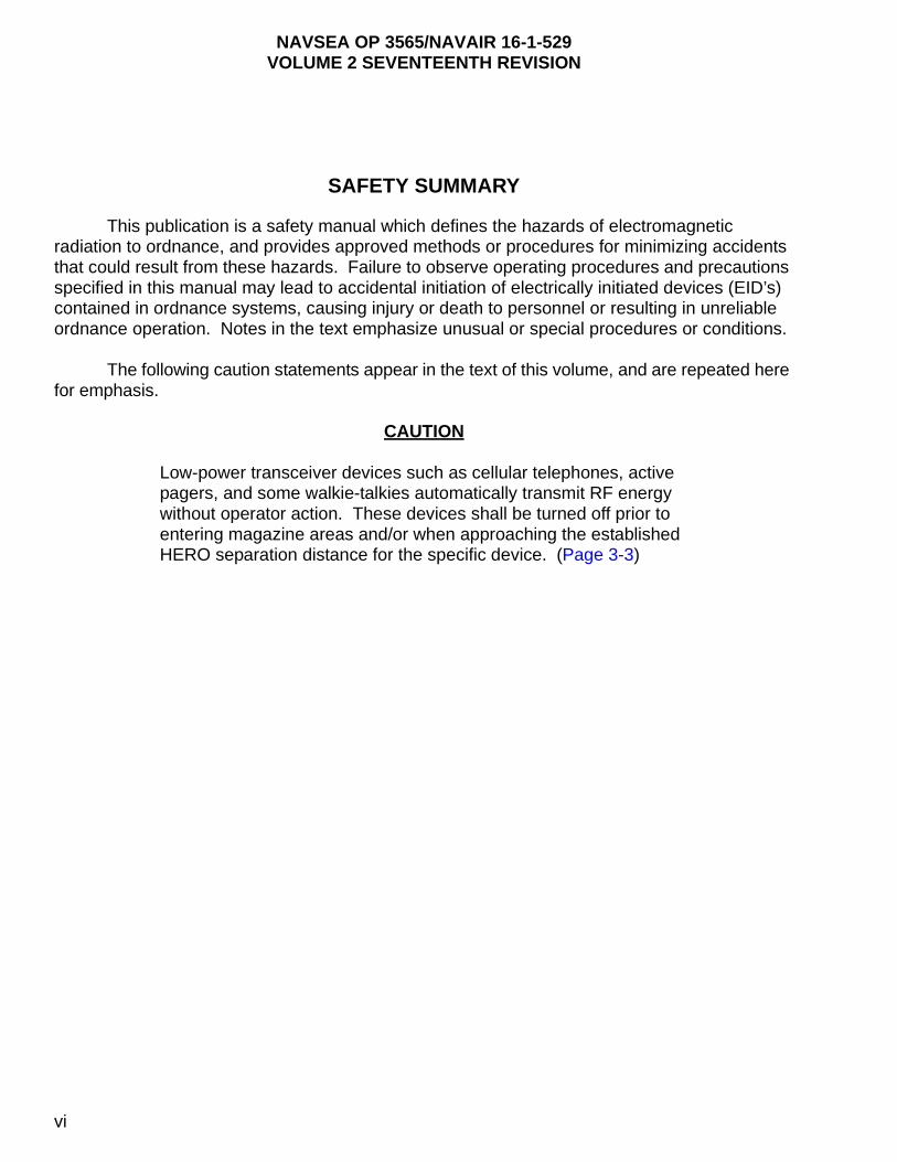
SAFETY SUMMARY
This publication is a safety manual which defines the hazards of electromagnetic radiation to ordnance, and provides approved methods or procedures for minimizing accidents that could result from these hazards. Failure to observe operating procedures and precautions specified in this manual may lead to accidental initiation of electrically initiated devices (EID’s) contained in ordnance systems, causing injury or death to personnel or resulting in unreliable ordnance operation. Notes in the text emphasize unusual or special procedures or conditions.
The following caution statements appear in the text of this volume, and are repeated here for emphasis.
CAUTION
Low-power transceiver devices such as cellular telephones, active pagers, and some walkie-talkies automatically transmit RF energy without operator action. These devices shall be turned off prior to entering magazine areas and/or when approaching the established HERO separation distance for the specific device. (Page 3-3)
NAVSEA OP 3565/NAVAIR 16-1-529VOLUME 2 SEVENTEENTH REVISION
CHAPTER 1
INTRODUCTION
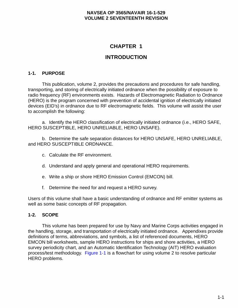
1-1. PURPOSE
This publication, volume 2, provides the precautions and procedures for safe handling, transporting, and storing of electrically initiated ordnance when the possibility of exposure to radio frequency (RF) environments exists. Hazards of Electromagnetic Radiation to Ordnance (HERO) is the program concerned with prevention of accidental ignition of electrically initiated devices (EID’s) in ordnance due to RF electromagnetic fields. This volume will assist the user to accomplish the following:
a. Identify the HERO classification of electrically initiated ordnance (i.e., HERO SAFE, HERO SUSCEPTIBLE, HERO UNRELIABLE, HERO UNSAFE).
b. Determine the safe separation distances for HERO UNSAFE, HERO UNRELIABLE, and HERO SUSCEPTIBLE ORDNANCE.
c. Calculate the RF environment.
d. Understand and apply general and operational HERO requirements.
e. Write a ship or shore HERO Emission Control (EMCON) bill.
f. Determine the need for and request a HERO survey.
Users of this volume shall have a basic understanding of ordnance and RF emitter systems as well as some basic concepts of RF propagation.
1-2. SCOPE
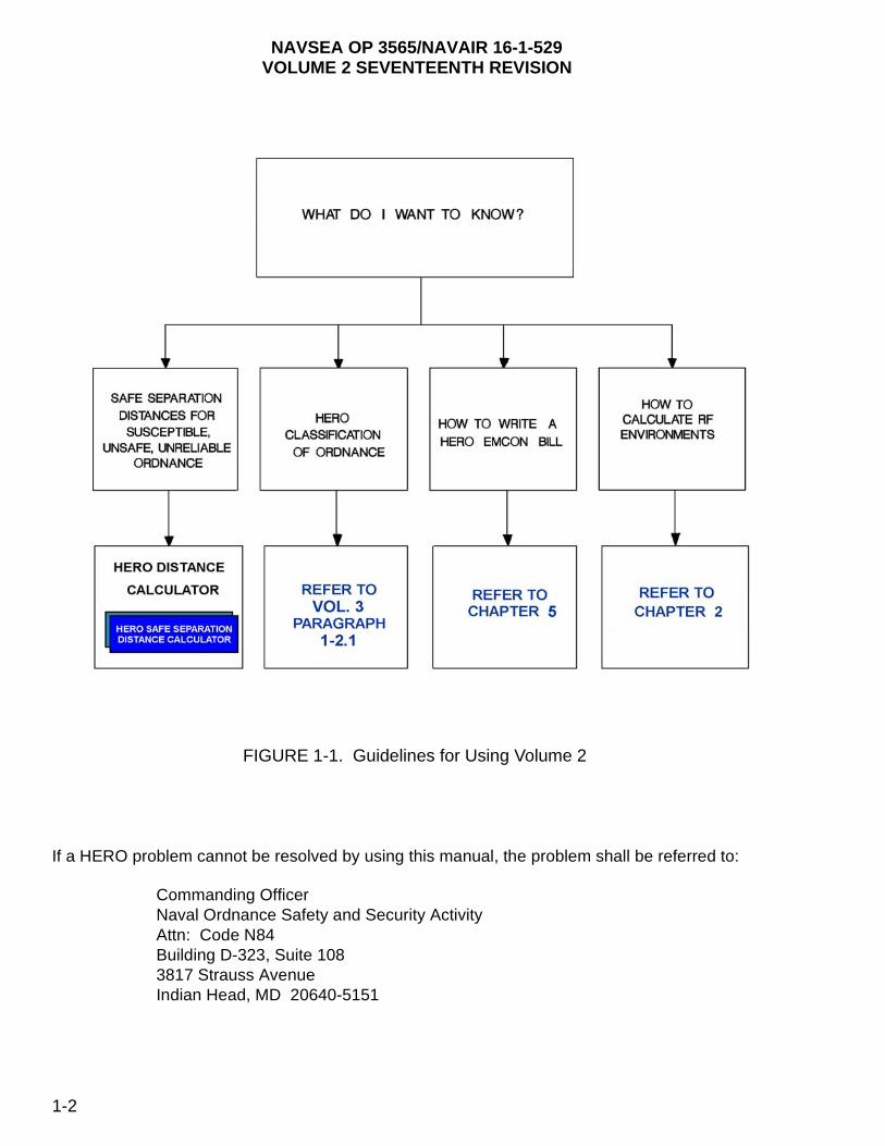
This volume has been prepared for use by Navy and Marine Corps activities engaged in the handling, storage, and transportation of electrically initiated ordnance. Appendixes provide definitions of terms, abbreviations, and symbols, a list of referenced documents, HERO EMCON bill worksheets, sample HERO instructions for ships and shore activities, a HERO survey periodicity chart, and an Automatic Identification Technology (AIT) HERO evaluation process/test methodology. Figure 1-1 is a flowchart for using volume 2 to resolve particular HERO problems.
1-1
NAVSEA OP 3565/NAVAIR 16-1-529VOLUME 2 SEVENTEENTH REVISION
If a HERO problem cannot be resolved by using this manual, the problem shall be referred to:
Commanding OfficerNaval Ordnance Safety and Security ActivityAttn: Code N84Building D-323, Suite 1083817 Strauss AvenueIndian Head, MD 20640-5151
FIGURE 1-1. Guidelines for Using Volume 2
‘
1-2

NAVSEA OP 3565/NAVAIR 16-1-529VOLUME 2 SEVENTEENTH REVISION
1-3. BACKGROUND
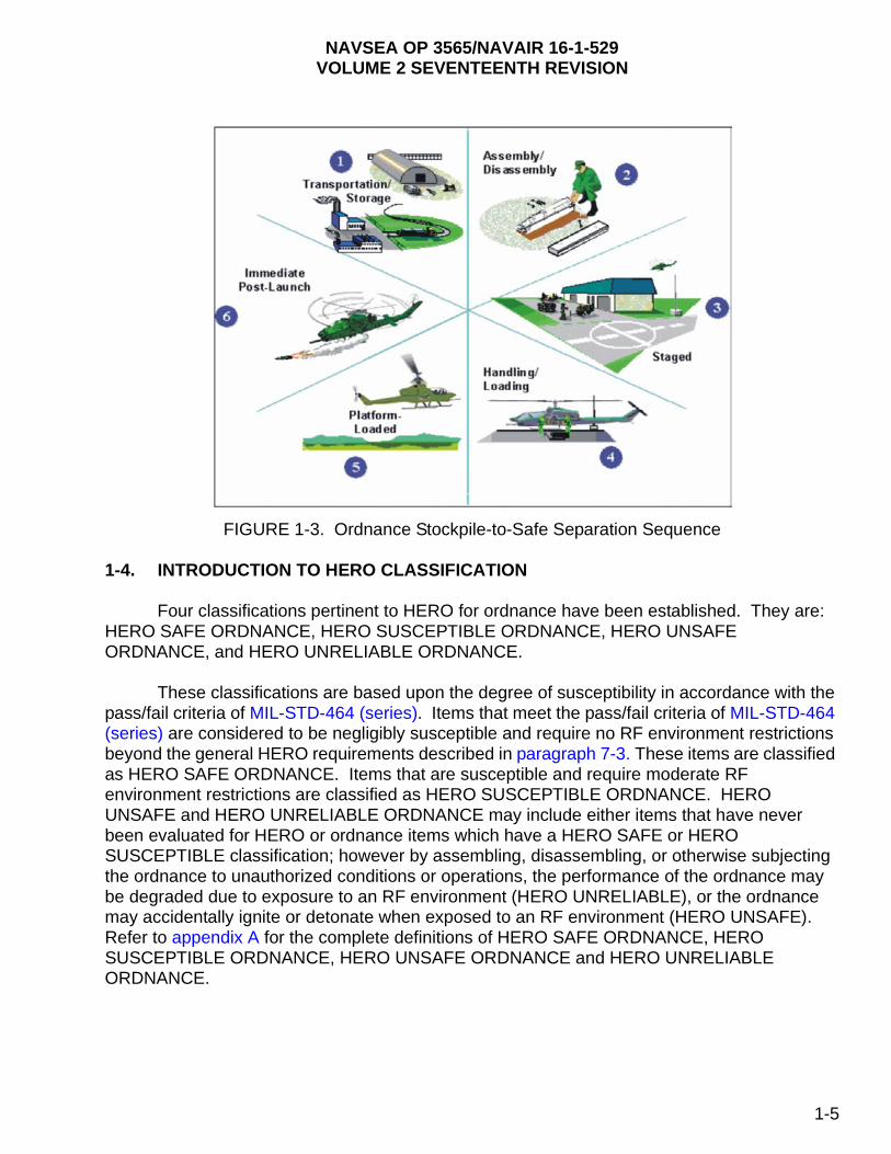
Electromagnetic radiation (EMR) hazards stem from the functional characteristics of electrically initiated ordnance. This EMR hazard is the result of absorption of electromagnetic (EM) energy by the firing circuitry of EID’s. Consequently, the induced energy causes heating of the EID’s bridgewire and primary explosive with which it is normally coated. (See figure 1-2). The ordnance EID's may be accidentally initiated or their performance degraded by exposure to RF environments. In general, ordnance is most susceptible to RF environments during assembly, disassembly, handling, loading, and unloading. However, the HERO program (both surveys and testing efforts) emphasizes exposure of ordnance to the Electromagnetic Environment (EME) levels that are associated with each Stockpile-to-Safe Separation Sequence (S4) phase. Figure 1-3 illustrates a typical progression through this sequence.
FIGURE 1-2. Example of an EID
Significant differences in the physical configuration of the ordnance item can be expected as the item transitions from one phase to another. Different physical configurations can provide different levels of protection. Furthermore, it is likely that the EME associated with each phase will be quite different. For example, the EME levels associated with handling/loading operations (at the flight deck or weather deck level) are generally less than those encountered during platform-loaded (main-beam levels). Thus, the potential for a HERO problem is highly dependent on both of these phase-dependent conditions. From a HERO test standpoint, it is especially important to test all unique ordnance configurations. In the past, only two configurations were defined: handling/loading and presence; therefore, in previous revisions to this volume, HERO data sheets only address these two configurations. Data found in the data sheets of volume 3 assume the following "mapping" order: transportation/storage data map into the transportation/storage category; loading/unloading data map into the handling/loading category; and staged, platform/system-loaded and immediate post-launch map into the
1-3

NAVSEA OP 3565/NAVAIR 16-1-529VOLUME 2 SEVENTEENTH REVISION
presence category. Assembly and disassembly operations are addressed in chapter 1 as fundamentally HERO UNSAFE ORDNANCE operations due to the exposure of internal circuitry or the addition of external wiring during check-out of the item.
1-3.1 THE NEED FOR HERO CONTROL. Technological advances have resulted in the development of extremely powerful communication and radar equipment that radiate high levels of EM energy. These advances, coupled with the trend to use more sensitive, low-power electronic circuits in the design of ordnance systems, perpetuate a long-standing hazard. The hazards that result from adverse interactions between the EME and the electrical initiators or initiating systems contained within ordnance systems are referred to in Department of Defense (DoD) terminology as HERO. The need for HERO control arises from a fundamental incompatibility between the EID’s or EID firing circuits contained within the ordnance and the external radiated EME that the ordnance encounters during its progression through the S4.
1-3.1.1 EID’s perform a variety of functions, such as initiating rocket motors, arming and detonating warheads, and ejecting chaff and flares. The need for HERO control arises so that these functions do not occur unintentionally or prematurely because of exposure to EM energy. There are two potential forms of such unintentional, RF-induced EID response:
a. Activation of the initiating device itself by EM energy coupled directly into the device or upset of an energized firing circuit, resulting in a firing signal erroneously sent to the EID.
b. Degradation or dudding of the initiating device by EM energy coupled directly into the device.
1-3.1.2 In the first case, accidental EID activation can have negative consequences on safety (for example, the premature initiation of explosive trains) or on reliability (for example, once initiated, EID’s can no longer perform their intended function, thus rendering the system incapable of performing its mission). In the second case, the presence of EM energy in an EID can alter its ignition properties without actually firing the device, so the device will not function when legitimate firing stimuli are applied; most likely, this will adversely affect system reliability. The combination of severe EME levels and sensitive, insufficiently protected components/circuits can have disastrous consequences. Although the problem was recognized in the late 1950s, it has persisted even today for two reasons: first, the introduction of more powerful emitters has raised operational EME levels, and second, the use of sensitive electrically initiated systems has continued.
1-3.1.3 Today, MIL-STD-464 (series) requires that ordnance be designed to provide sufficient protection from the EME and that its performance be verified by testing and/or by an analysis by a DoD facility.
1-3.1.4 Given this reality, HERO EMCON and ordnance handling restrictions form a compromise which allows safe ordnance operations ashore and at sea. EMCON are derived from an analysis of the fields produced by the existing RF transmitters or by direct measurement during HERO surveys and the ordnance susceptibilities described in this manual. Handling restrictions are the result of ordnance system tests performed under worst-case conditions using actual handling and loading procedures. The data gathered from these tests are the basis for the HERO classifications and recommendations in volume 3.
1-4
NAVSEA OP 3565/NAVAIR 16-1-529VOLUME 2 SEVENTEENTH REVISION
FIGURE 1-3. Ordnance Stockpile-to-Safe Separation Sequence
1-4. INTRODUCTION TO HERO CLASSIFICATION
Four classifications pertinent to HERO for ordnance have been established. They are: HERO SAFE ORDNANCE, HERO SUSCEPTIBLE ORDNANCE, HERO UNSAFE ORDNANCE, and HERO UNRELIABLE ORDNANCE.
These classifications are based upon the degree of susceptibility in accordance with the pass/fail criteria of MIL-STD-464 (series). Items that meet the pass/fail criteria of MIL-STD-464 (series) are considered to be negligibly susceptible and require no RF environment restrictions beyond the general HERO requirements described in paragraph 7-3. These items are classified as HERO SAFE ORDNANCE. Items that are susceptible and require moderate RF environment restrictions are classified as HERO SUSCEPTIBLE ORDNANCE. HERO UNSAFE and HERO UNRELIABLE ORDNANCE may include either items that have never been evaluated for HERO or ordnance items which have a HERO SAFE or HERO SUSCEPTIBLE classification; however by assembling, disassembling, or otherwise subjecting the ordnance to unauthorized conditions or operations, the performance of the ordnance may be degraded due to exposure to an RF environment (HERO UNRELIABLE), or the ordnance may accidentally ignite or detonate when exposed to an RF environment (HERO UNSAFE). Refer to appendix A for the complete definitions of HERO SAFE ORDNANCE, HERO SUSCEPTIBLE ORDNANCE, HERO UNSAFE ORDNANCE and HERO UNRELIABLE ORDNANCE.
1-5

NAVSEA OP 3565/NAVAIR 16-1-529VOLUME 2 SEVENTEENTH REVISION
NOTE
The preceding classifications do not apply to percussion-initiated devices or systems. Ordnance or equipment which does not contain EID’s has no HERO requirement.
In the chapters that follow, the reader will be instructed as to how to determine the HERO classification of an item to be handled.
1-5. MANAGING HERO
In general, risk-reduction measures developed using analytical methods may entail silencing all emitters during ordnance operations, ensuring ordnance operations are conducted in RF-free environments, or imposing safe separation distances between the offending emitters and HERO SUSCEPTIBLE and HERO UNSAFE ORDNANCE. Unfortunately, these methods are very restrictive and do not allow for operational flexibility. For HERO, the term RF-free environment refers to a condition that exists in magazines where the use of intentional RF emitters are restricted/controlled, and the ambient EME is well below the HERO UNSAFE ORDNANCE curve presented in figure 2-2.
1-5.1 ASSESSMENT OF RISK. Managing HERO through the use of HERO EMCON bills, particularly those derived from instrumented HERO surveys where the RF environment is characterized through measurements, provides the least operationally restricted environment for fleet operations. HERO EMCON bills are a result of a risk assessment involving the comparison of a known or assumed susceptibility for ordnance, expressed as the maximum allowable environment (MAE), against the expected operational EME. If the EME levels exceed the MAE levels, there is a risk of inadvertent initiation of EID’s, with negative consequences regarding safety and/or reliability.
1-5.2 NAVY-UNIQUE CLASSIFICATIONS. HERO EMCON bills are written to specify emitter restrictions for each Navy ship and shore station when maximum operational EME levels exceed the MAE’s for susceptible items at respective ordnance locations. The Navy categorizes all ordnance in terms of the relative immunity. For example, HERO SAFE ORDNANCE is designated for ordnance that can be exposed safely to EME levels as high as those specified in MIL-STD-464 (series). HERO UNSAFE ORDNANCE and HERO SUSCEPTIBLE ORDNANCE designations are reserved for items that have known susceptibilities revealed by a test or an analysis or have not been certified based on the HERO requirements in MIL-STD-464 (series). These terms, or HERO classifications, are Service-unique to the Navy, but provide a convenient means for identifying whether or not a HERO concern exists during ordnance operations. The HERO EMCON bill cites each ordnance item stored or handled aboard a ship or shore station, as well as any required local emitter restrictions necessary for safe operations.
1-6. TRI-SERVICE APPROACH TO HERO
The basic DoD HERO requirements for design and performance verification are found in MIL-STD-464 (series); however, because of the varied experiences with HERO within the Services, it is not surprising that Service-unique approaches have evolved over time to deal with HERO problems. Army, Navy, and Air Force HERO programs reflect fundamental
1-6
NAVSEA OP 3565/NAVAIR 16-1-529VOLUME 2 SEVENTEENTH REVISION
differences in the perception of the problem’s magnitude. Besides Service histories, other factors have influenced the respective HERO programs, such as the way the Services store, transport, and use ordnance, and the practical options available for minimizing hazards. For example, when operational EME levels exceed susceptibility thresholds, the Services can opt to use different risk-reduction measures. The Army and Air Force, for example, might stipulate a minimum separation distance between the susceptible ordnance and the offending transmitter; whereas, limited space aboard naval platform/systems might leave no other option for the Navy than to impose restrictions on the emissions of the offending transmitter(s). Here, various methods are employed such as frequency management, reducing the transmitter output power, or limiting the antenna radiation zones, all of which are employed in a Navy HERO EMCON bill in order to manage HERO while minimizing the operational restrictions.
1-6.1 COMMON APPROACHES. Despite differences in the way each Service manages HERO problems, there are certain essential elements that are common to all Services’ HERO programs. These include the following:
a. A definition of the expected EME levels for all ordnance configurations.
b. Prescribed methods to quantify system degradation or deficiencies.
c. A process to develop and validate effective, practical “fixes” for known HERO deficiencies.
d. Establishment of operational procedures or restrictions to minimize risks when deficiencies are not corrected.
1-6.2 DOD-WIDE APPLICATION. It is important to note that the HERO SUSCEPTIBLE and HERO UNSAFE curves found in chapter 2 were derived from a tri-Service effort; whereby, all HERO test data for each of the Services were reviewed and a common rationale was used to develop the curves. Thus, the HERO curves found within this document can be used for all U.S. DoD ordnance when calculating safe separation distances once it has been established that the ordnance item is either HERO SUSCEPTIBLE or HERO UNSAFE ORDNANCE.
1-7. PERSONNEL REQUIREMENTS
1-7.1 TRAINING. All personnel engaged in operations involving ordnance shall be familiar with all phases of work which they will be required to perform. In addition, they shall be made aware of the proper methods for performing tasks that will be in progress in their work area.
a. Personnel shall be provided with instruction in the following:
(1) RF radiation and laser hazards as described in volume 1.
(2) Identification of equipment and/or ordnance by markings.
(3) Placards, warning signs, and painted safety circles and zones.
(4) Selection and use of test equipment and proper test procedures.
1-7

NAVSEA OP 3565/NAVAIR 16-1-529VOLUME 2 SEVENTEENTH REVISION
(5) RF hazard sources.
(6) Characteristics of existing, modified, or new equipment/ordnance.
(7) Proper loading/unloading procedures for ordnance; proper procedures for ordnance transfer ashore and at sea.
(8) The functions of each individual engaged in the operation(s) to be performed.
(9) The proper use of this manual.
(10) The ability to verify that the appropriate HERO EMCON procedures have been set as outlined in the ship- or shore-specific HERO EMCON bill.
b. Follow-up retraining sessions shall be provided upon changes in personnel, ordnance, or equipment, and/or as directed by the commanding officer.
c. Personnel shall be familiar with current HERO warning symbols and labels described in paragraph 1-8.
1-7.2 SAFETY PRECAUTIONS. The problems resulting from personnel and ordnance exposure to RF energy, can be mitigated if all personnel follow the safety regulations as prescribed herein. It is the responsibility of the commanding officer of each ship or shore station to implement the requirements contained in this volume. Procedures shall be established whereby RF transmitting equipment is positively controlled and coordinated with personnel working near emitters and/or handling ordnance. No personnel shall turn on any transmitting equipment without proper authorization from the supervisor in charge of operations. Procedures for controlling laser operations shall also be generated as described in volume 1.
1-8. HERO WARNING SYMBOLS AND LABELS
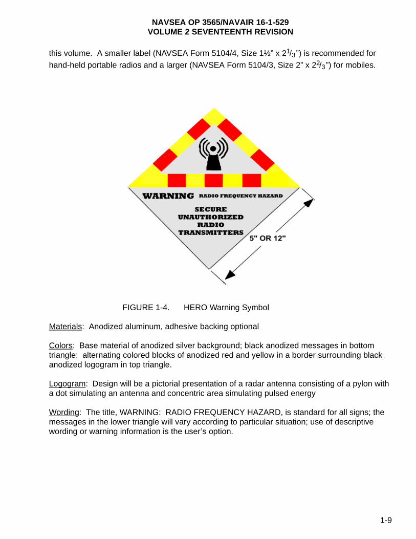
1-8.1 HERO WARNING SYMBOLS. Warning symbols shall be posted at any location where radar equipment or other possible sources of EMR might create the potential for premature initiation of ordnance due to HERO. An example of an RF warning symbol is shown in figure 1-4. This symbol is placed along ordnance transportation routes at prescribed locations to ordnance operations (e.g., missile assembly, ammunition pier, etc.) to alert operators of mobile and portable emitter systems such as radios and cellular telephones to a potential hazard when using radios and cellular telephones past this point. Guidance for manufacturing symbols is provided below.
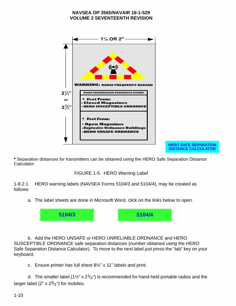
1-8.2 HERO WARNING LABELS. Warning labels are to be affixed to portable and mobile radios, and are for use both on ship and shore stations. An example of an RF warning label is shown in figure 1-5. The HERO warning label is to be affixed to mobile and portable emitter systems such as radios and cellular telephones. This warning label alerts the emitter operator to a potential hazard if the emitter is operated within the prescribed distance of ordnance operations. The label has blank spaces for inserting HERO SUSCEPTIBLE, HERO UNSAFE, or HERO UNRELIABLE separation distances in feet. The distances are obtained by using the HERO Safe Separatoin Distance Calculator, which is presented and discussed in chapter 2 of
1-8
NAVSEA OP 3565/NAVAIR 16-1-529VOLUME 2 SEVENTEENTH REVISION
this volume. A smaller label (NAVSEA Form 5104/4, Size 1½” x 21/3”) is recommended for
hand-held portable radios and a larger (NAVSEA Form 5104/3, Size 2” x 22/3”) for mobiles.
FIGURE 1-4. HERO Warning Symbol
Materials: Anodized aluminum, adhesive backing optional
Colors: Base material of anodized silver background; black anodized messages in bottom triangle: alternating colored blocks of anodized red and yellow in a border surrounding black anodized logogram in top triangle.
Logogram: Design will be a pictorial presentation of a radar antenna consisting of a pylon with a dot simulating an antenna and concentric area simulating pulsed energy
Wording: The title, WARNING: RADIO FREQUENCY HAZARD, is standard for all signs; the messages in the lower triangle will vary according to particular situation; use of descriptive wording or warning information is the user’s option.
1-9
NAVSEA OP 3565/NAVAIR 16-1-529VOLUME 2 SEVENTEENTH REVISION
N R
* Separation distances for transmitters can be obtained using the HERO Safe Separation Distance Calculator.
FIGURE 1-5. HERO Warning Label
1-8.2.1 HERO warning labels (NAVSEA Forms 5104/3 and 5104/4), may be created as follows:
a. The label sheets are done in Microsoft Word, click on the links below to open.
b. Add the HERO UNSAFE or HERO UNRELIABLE ORDNANCE and HERO SUSCEPTIBLE ORDNANCE safe separation distances (number obtained using the HERO Safe Separation Distance Calculator). To move to the next label just press the “tab” key on your keyboard.
c. Ensure printer has full sheet 8½” x 11” labels and print.
d. The smaller label (1½” x 21/3”) is recommended for hand-held portable radios and the
larger label (2” x 22/3”) for mobiles.
HERO SAFE SEPARATIODISTANCE CALCULATO
5104/3 5104/4
1-10
NAVSEA OP 3565/NAVAIR 16-1-529VOLUME 2 SEVENTEENTH REVISION
NOTE
Avery label paper 8255 has an adhesive backing and can be cut to corresponding size. Avery label paper can be found at most office supply stores.
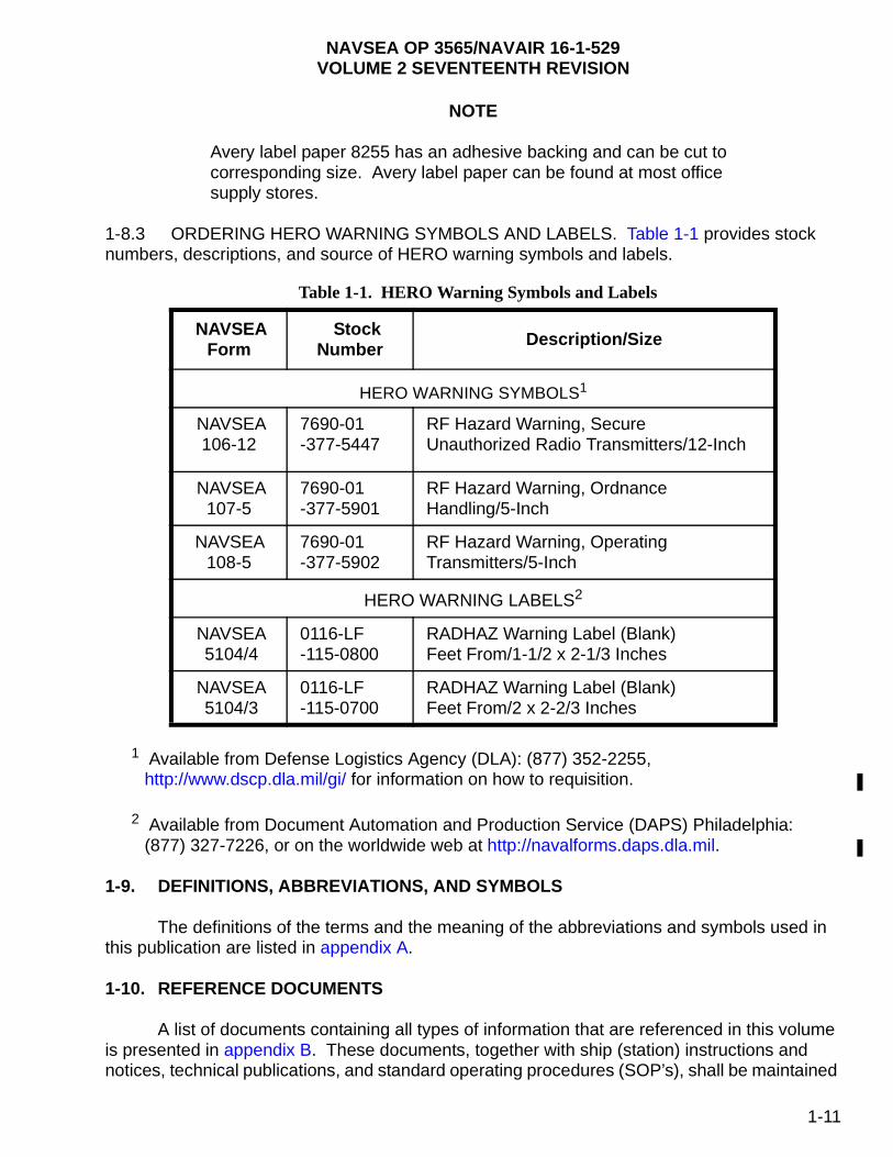
1-8.3 ORDERING HERO WARNING SYMBOLS AND LABELS. Table 1-1 provides stock numbers, descriptions, and source of HERO warning symbols and labels.
1 Available from Defense Logistics Agency (DLA): (877) 352-2255, http://www.dscp.dla.mil/gi/ for information on how to requisition.
2 Available from Document Automation and Production Service (DAPS) Philadelphia: (877) 327-7226, or on the worldwide web at http://navalforms.daps.dla.mil.
1-9. DEFINITIONS, ABBREVIATIONS, AND SYMBOLS
The definitions of the terms and the meaning of the abbreviations and symbols used in this publication are listed in appendix A.
1-10. REFERENCE DOCUMENTS
A list of documents containing all types of information that are referenced in this volume is presented in appendix B. These documents, together with ship (station) instructions and notices, technical publications, and standard operating procedures (SOP’s), shall be maintained
Table 1-1. HERO Warning Symbols and Labels
NAVSEA Form
Stock Number Description/Size
HERO WARNING SYMBOLS1
NAVSEA 106-12
7690-01 -377-5447
RF Hazard Warning, Secure Unauthorized Radio Transmitters/12-Inch
NAVSEA 107-5
7690-01 -377-5901
RF Hazard Warning, Ordnance Handling/5-Inch
NAVSEA 108-5
7690-01 -377-5902
RF Hazard Warning, Operating Transmitters/5-Inch
HERO WARNING LABELS2
NAVSEA 5104/4
0116-LF -115-0800
RADHAZ Warning Label (Blank) Feet From/1-1/2 x 2-1/3 Inches
NAVSEA 5104/3
0116-LF -115-0700
RADHAZ Warning Label (Blank) Feet From/2 x 2-2/3 Inches
1-11
NAVSEA OP 3565/NAVAIR 16-1-529VOLUME 2 SEVENTEENTH REVISION
in appropriate libraries as a collection of current information pertaining to the hazards of RF radiation to ordnance which contain EID’s.
1-11. DATE OF PUBLICATION
The date of publication of this technical manual, and of revisions and changes thereto, as shown on the title page, is the estimated date the publication is to be distributed. The manual, revision, or change, is, however, effective upon receipt, regardless of the date shown on the title page.
1-12. HERO DATA SHEET PROFILE TOOL
Volume 3 of this manual contains HERO data sheets for all of the ordnance systems or items containing electrically initiated devices that have been analyzed by design or tested for HERO. Due to its size, it is not recommended that the entire volume be printed in order to maintain a paper record of HERO data for assets on hand for a particular ship/activity. The HERO Data Sheet Profile Tool is an electronic device that enables ordnance/communications officers and personnel to develop a HERO data sheet file unique to their use. Based on ship or activity needs, a profile may be generated based on NALC/DODIC, platform, launcher, or container. To use, select criteria, then view or print HERO data sheets applicable to criteria chosen. Numerous choices may be made.
1-12
NAVSEA OP 3565/NAVAIR 16-1-529VOLUME 2 SEVENTEENTH REVISION
CHAPTER 2
RF ENVIRONMENTS
2-1. METHODS FOR CONTROLLING THE RF ENVIRONMENT
The sources for electromagnetic environment (EME) levels that exist at ship and shore facilities have been collected during Hazards of Electromagnetic Radiation to Ordnance (HERO), Hazards of Electromagnetic Radiation to Personnel (HERP), and flight deck EME surveys and that data can be found within the survey reports. In addition, main-beam calculations can be obtained once the transmitter and antenna specifications are known. These data can be found in transmitter databases, manufacturers’ data sheets, technical manuals, HERO reports, HERP reports, and flight-deck EME survey reports.
The ensuing paragraphs are provided so that users of the HERO curves (figures 2-1 and 2-2) and the HERO Safe Separation Distance Calculator, understand the use and limitations of these tools. For example, when using the HERO Safe Separation Distance Calculator, it is important to use average power (and not peak power) as the input parameter for calculating a safe separation distance. It is the average power that most often influences electrically initiated devices (EID’s). For the HERO curves and the associated equations, it is important to understand that the results given are only accurate in the far field and, consequently, discussions related to the field regions associated with an antenna are provided. For example, if one were to manipulate the equations to solve for a power density/field intensity at a new distance, the results might not accurately reflect the true value. For calculating values in the near field of an antenna, one would need to use the equations found in NAVSEA OP 3565 Volume 1. Consequently, this chapter introduces information germane to calculating radio-frequency (RF) environments and helps provide a better understanding of the use of these tools.
2-1.1 PEAK AND AVERAGE POWER CALCULATIONS. Typically, communication systems are capable of modulation techniques, such as amplitude modulation (AM), frequency modulation (FM), and pulse–code modulation (PCM), or continuous wave (CW). In order to determine the root mean squared (rms) peak power for FM and PCM, a worst-case approach is used where the peak power is equal to the unmodulated carrier peak power. However, the peak envelope power (PEP) of a 100% modulated AM signal is twice the carrier peak power and, therefore, is used to provide the worst-case scenario from AM signals. Also, the duty cycle of a CW signal equals unity and the average and peak rms power are the same. The aforementioned rationale is used when calculating EME’s because of the randomly changing nature of true peak power over a specific interval.
Pulse-modulated signals, typically radars, have differences between peak and average rms power. The average power is determined by the ratio of time-on to time-off over an interval. This time-on/off ratio is the duty cycle (DC) and can be calculated using equation (2-1). The average power can be calculated by the product of peak power and duty cycle as shown in equation (2-2).
2-1
NAVSEA OP 3565/NAVAIR 16-1-529VOLUME 2 SEVENTEENTH REVISION
or (2-1)
(2-2)
where
= the duty cycle (unitless)
= the pulse width (sec)
= the pulse repetition rate interval (sec)
= the pulse repetition rate frequency (Hz)
= the average power (watts)
= the peak power (watts)
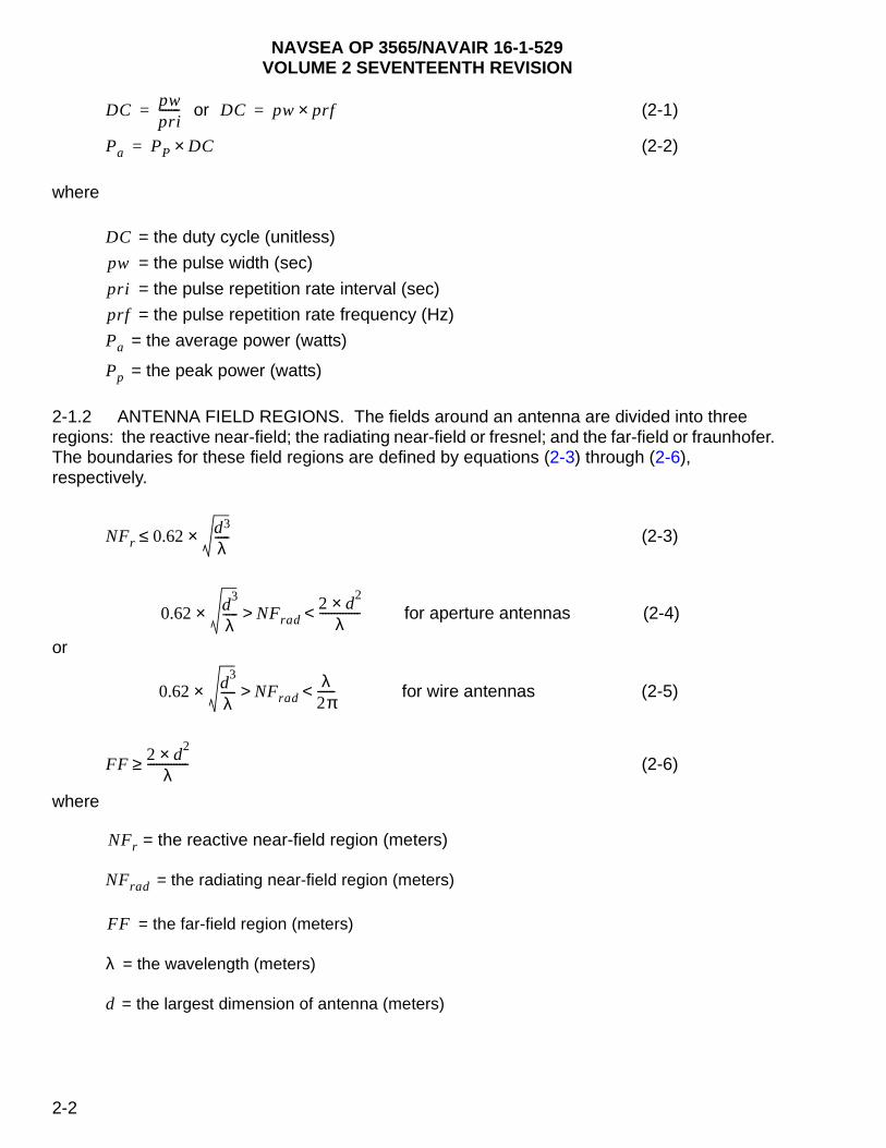
2-1.2 ANTENNA FIELD REGIONS. The fields around an antenna are divided into three regions: the reactive near-field; the radiating near-field or fresnel; and the far-field or fraunhofer. The boundaries for these field regions are defined by equations (2-3) through (2-6), respectively.
(2-3)
for aperture antennas (2-4)
or
for wire antennas (2-5)
(2-6)
where
= the reactive near-field region (meters)
= the radiating near-field region (meters)
= the far-field region (meters)
= the wavelength (meters)
= the largest dimension of antenna (meters)
DCpwpri-------= DC pw prf×=
Pa PP DC×=
DC
pw
pri
prf
Pa
Pp
NFr 0.62 d3
λ-----×≤
0.62 d3
λ-----× NFrad
2 d2×
λ--------------<>
0.62 d3
λ-----× NFrad
λ2π------<>
FF2 d
2×λ
--------------≥
NFr
NFrad
FF
λ
d
2-2

NAVSEA OP 3565/NAVAIR 16-1-529VOLUME 2 SEVENTEENTH REVISION
NOTE
If the antenna is small compared to the wavelength ( > 10d), the radiating near-field does not exist.
2-1.3 POWER DENSITY AND FIELD INTENSITY CALCULATIONS. The HERO Safe Separation Distance Calculator and safe separation distances are all derived using a far-field equation. In the far-field region, the power density is calculated using equation (2-7). All power density levels are calculated within the 3 dB beam width of the main beam.
(2-7)
where
= the power density (watts/meter2)
= the average or peak transmitter output power (watts)
= the numerical antenna gain (unitless)
= the distance or range from the antenna (meters)
In the near-field region, the power densities are calculated using the far-field equation (2-7) and a near-field gain reduction factor N. See NAVSEA OP 3565 Volume 1, for calculation of the near-field gain reduction factor. Power density is related to the electric field by equation (2-8). When converting from power density to field intensity (or vice versa), the following relationship only exists for a plane wave (within the far field of the antenna where the relationship between the electric field and magnetic field is orthogonal and clearly defined).
(2-8)
where
= the maximum electric field strength (V/m-rms)
= the intrinsic impedance of free space (120π or approximately 377 Ω)
= the power density (watts/meter2)
In the near-field region, an antenna’s electric and magnetic fields do not exhibit a constant ratio of 120 (approximately 377 Ω), the intrinsic impedance of free space. Depending on the source antenna’s terminal voltage, impedance, and driver current, the electric and magnetic fields will vary at different rates where one field becomes dominant. As the far-field region is approached, the ratio of the electric and magnetic fields begins to approximate 377 Ω; variation between the fields becomes less, and any dominants of one field are reduced.
λ
Pd
PT G×
4 π r2××
-----------------------=
Pd
PT
G
r
E Pd Zo×=
E
Zo
Pd
2-3
NAVSEA OP 3565/NAVAIR 16-1-529VOLUME 2 SEVENTEENTH REVISION
2-2. FIELD STRENGTH/DISTANCE RESTRICTIONS
Figures 2-1 and 2-2 have been prepared on the basis of worst-case conditions for all HERO SUSCEPTIBLE, HERO UNSAFE, and HERO UNRELIABLE ORDNANCE and may be used in determining the maximum RF environment for any ordnance system when specific Maximum Allowable Environment (MAE) susceptibility data are not available or for ordnance that has not been HERO evaluated.
NOTE
Calculations in this chapter provide a relatively accurate measure of the maximum field strength at shore transmitter sites. They may be used for shipboard transmitters; however, the results are subject to beam reflections that may cause severe power differences from those calculated. The only accurate gauge of shipboard power density/field intensity is actual measurement data obtained through a HERO survey.
Data sheets are presented in NAVSEA OP 3565/NAVAIR 16-1-529 Volume 3 for all Naval HERO Program-evaluated ordnance that has been tested/analyzed against known environments. Individual data sheets generally provide MAE’s that are less restrictive than the MAE’s presented in the general HERO curves shown in figures 2-1 and 2-2. The HERO curves are also the basis for the equations found in the HERO Safe Separation Distance Calculator. Hence, the HERO curves provide a means for determining a general MAE for HERO SUSCEPTIBLE and HERO UNSAFE ORDNANCE when no specific MAE data are available, while the HERO Safe Separation Distance Calculator applies equation (2-7) to those equations to allow for a calculated safe separation distance for HERO SUSCEPTIBLE and HERO UNSAFE ORDNANCE when no measured data are available.
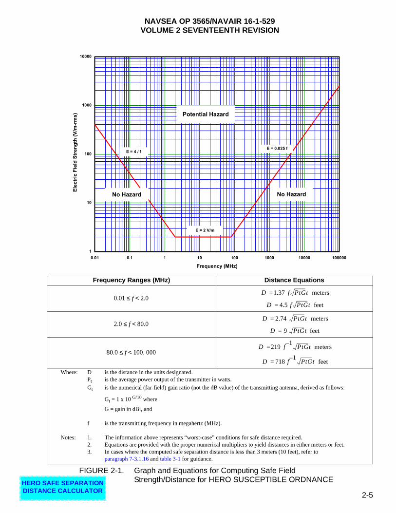
2-2.1 SAFE FIELD STRENGTH/DISTANCE CALCULATION. The maximum safe field strengths for the various frequency ranges for HERO SUSCEPTIBLE, HERO UNSAFE, and HERO UNRELIABLE ORDNANCE, shown on figures 2-1 and 2-2, when applied to the basic distance field strength equation, will determine the "worst-case" safe distance. The safe field strength/distance equations for HERO SUSCEPTIBLE ORDNANCE are derived from figure 2-1. The safe field strength/distance equations for HERO UNSAFE and HERO UNRELIABLE ORDNANCE are derived from figure 2-2. When using HERO equations and the HERO Safe Separation Distance Calculator to determine a safe separation distance, it is the average power of a transmitter, the antenna gain in dBi, and the lowest operational frequency of the transmitter that are used to calculate the safe separation distances. The HERO Safe Separation Distance Calculator for these equations is available by clicking on the button below.
HERO SAFE SEPARATION DISTANCE CALCULATOR
2-4
NAVSEA OP 3565/NAVAIR 16-1-529VOLUME 2 SEVENTEENTH REVISION
HERO DISTA
FIGURE 2-1. Graph and Equations for Computing Safe Field Strength/Distance for HERO SUSCEPTIBLE ORDNANCE
Frequency Ranges (MHz) Distance Equations
meters
feet
meters
feet
meters
feet
Where: D is the distance in the units designated.Pt is the average power output of the transmitter in watts.
Gt is the numerical (far-field) gain ratio (not the dB value) of the transmitting antenna, derived as follows:
Gt = 1 x 10 G/10 where
G = gain in dBi, and
f is the transmitting frequency in megahertz (MHz).
Notes: 1. The information above represents “worst-case” conditions for safe distance required.2. Equations are provided with the proper numerical multipliers to yield distances in either meters or feet.3. In cases where the computed safe separation distance is less than 3 meters (10 feet), refer to
paragraph 7-3.1.16 and table 3-1 for guidance.
1
10
100
1000
10000
0.01 0.1 1 10 100 1000 10000 100000
Frequency (MHz)
Ele
ctr
ic F
ield
Str
en
gth
(V
/m-r
ms) Potential Hazard
No Hazard No Hazard
E = 2 V/m
E = 4 / fE = 0.025 f
0.01 f 2.0<≤D 1.37 f PtGt=
D 4.5 f PtGt=
2.0 f 80.0<≤D 2.74 PtGt=
D 9 PtGt=
80.0 f 100 000,<≤D 219 f
1–PtGt=
D 718 f1–
PtGt=
SAFE SEPARATION NCE CALCULATOR
2-5

NAVSEA OP 3565/NAVAIR 16-1-529VOLUME 2 SEVENTEENTH REVISION
ARATION CULATOR
FIGURE 2-2. Graph and Equations for Computing Safe Field Strength/Distance for HERO UNSAFE and HERO UNRELIABLE ORDNANCE
Frequency Ranges (MHz) Distance Equations
meters
feet
meters
feet
meters
feet
Where: D is the distance in the units designated.Pt is the average power output of the transmitter in watts.
Gt is the numerical (far-field) gain ratio (not the dB value) of the transmitting antenna, derived as follows:
Gt = 1 x 10 G/10 where
G = gain in dBi, and
f is the transmitting frequency in megahertz (MHz)
Notes: 1. The information above represents “worst-case” conditions for safe distance required.2. Equations are provided with the proper numerical multipliers to yield distances in either meters or feet.3. In cases where the computed safe separation distance is less than 3 meters (10 feet), refer to
paragraph 7-3.1.16 and table 3-1 for guidance.
0.1
1.0
10.0
100.0
1000.0
0.01 0.1 1 10 100 1000 10000 100000
Frequency (MHz)
Ele
ctr
ic F
ield
Str
en
gth
(V
/m-r
ms) Potential Hazard
No Hazard No Hazard
E = 0.5 V/m
E = 1 / f E = 0.00625 f
0.01 f 2.0<≤D 5.5 f PtGt=
D 18 f PtGt=
2.0 f 80.0<≤D 10.95 PtGt=
D 36 PtGt=
80.0 f 100 000,<≤D 876 f
1–PtGt=
D 2 873 f1–
PtGt,=
HERO SAFE SEPDISTANCE CAL
2-6
NAVSEA OP 3565/NAVAIR 16-1-529VOLUME 2 SEVENTEENTH REVISION
2-2.2 RELAXATION OF 10-FOOT RULE. It is important to note that the HERO Safe Separation Distance Calculator provides safe separation distances for all ordnance and incorporates exceptions to the general requirement of a minimum 10-foot separation distance. In the past, the HERO philosophy was that there was to always be a 10-foot separation distance between all ordnance (including HERO SAFE ORDNANCE) and any transmitting antenna. (General guidance to this effect is found in chapter 7.) Due to the proliferation of low-power devices, a relaxation of the 10-foot rule has been built into the HERO Safe Separation Distance Calculator (discussions on these types of devices and an exceptions table are provided in table 3-1) so that these devices can be used closer than 10 feet to ordnance when required. Consequently, the HERO Safe Separation Distance Calculator may provide a safe separation distance of less than 10 feet for certain emitters when used around ordnance.
2-2.3 MULTIPLE SUPERIMPOSED FIELD CALCULATIONS. Whenever an RF field is found to be hazardous to a system, a method is determined to reduce the field to an acceptable safe level. To determine if superimposed fields (no one of which, acting independently, is sufficient to create a hazard) present a combined hazard to the ordnance system, use the formula:
where ET is the total electric field strength to be calculated and (E1), (E2), etc., are the individual field strengths to be added together.
NOTE
The calculated total field should then be compared with the maximum allowable field. If it is less, no hazard exists.
If a hazard exists, at least one transmitter must be silenced and the preceding formula recalculated, to determine if a safe condition now exists. If not, this process must be repeated until a combination of fields is found for which the total field is less than the maximum allowable field.
2-2.3.1 Example Calculation. A field strength of 10 V/m represents a hazardous condition for a particular rocket in the frequency range of 2 to 32 MHz. Assume that three radiating communication antennas (2 to 32 MHz) create fields of 8, 5, and 2 V/m, respectively, at the location in question. To determine if these superimposed fields represent a hazard to the rocket, calculate as follows:
, therefore,
V/m.
Since is less than 10 V/m, no hazard exists from the combination of these fields.
ET E1( )2E2( )2
E3( )2+ +=
ET
ET 8( )25( )2
2( )2+ +=
64 25 4+ +=
93=
ET 9.64=
ET
2-7

NAVSEA OP 3565/NAVAIR 16-1-529VOLUME 2 SEVENTEENTH REVISION
2-3. CONTROL OF RF ENVIRONMENTS
In the absence of specific shipboard or shore facility HERO emission control (EMCON) bill guidance (found in the HERO survey reports), the following paragraphs provide guidance for the control of RF environments during HERO SUSCEPTIBLE, HERO UNSAFE, and HERO UNRELIABLE ORDNANCE operations.
2-3.1 CONTROL OF RF ENVIRONMENTS FOR HERO SUSCEPTIBLE, HERO UNSAFE, AND HERO UNRELIABLE ORDNANCE. Ordnance classified as HERO SUSCEPTIBLE, HERO UNSAFE, or HERO UNRELIABLE must never be permitted in RF environments that exceed the MAE levels in figures 2-1 and 2-2. The commanding officer is responsible for ensuring that HERO UNSAFE ORDNANCE and HERO UNRELIABLE ORDNANCE are not handled in RF environments which exceed those shown by figure 2-2. By maintaining the calculated safe separation distances, the user can ensure that the RF environment does not exceed the MAE for HERO SUSCEPTIBLE, HERO UNSAFE, and HERO UNRELIABLE ORDNANCE. For the user’s convenience, and to aid in obtaining HERO distances and MAEs, a HERO Safe Separation Distance Calculator is available by clicking on the button below.
2-3.2 NOTIFICATION OF TRANSFER OF OTHER THAN HERO SAFE ORDNANCE. Cautionary measures should be taken to ensure that positive notification is given when HERO SUSCEPTIBLE, HERO UNSAFE, and HERO UNRELIABLE ORDNANCE is transferred from one ship or station to another. Methods of reducing environments to safe levels can be found within the HERO EMCON bills provided in the HERO survey reports.
HERO SAFE SEPARATION DISTANCE CALCULATOR
2-8
NAVSEA OP 3565/NAVAIR 16-1-529VOLUME 2 SEVENTEENTH REVISION
CHAPTER 3
USE OF RF EMITTERS IN PROXIMITY TO ORDNANCE
3-1. INTRODUCTION
Inasmuch as the Navy Hazards of Electromagnetic Radiation to Ordnance (HERO) program has been in existence for a number of years, a baseline HERO survey exists for each Navy and Marine Corps shore activity required to be surveyed and for each ship or ship-class. Within those survey reports, virtually all typical emitter systems (i.e., shipboard, fixed emitter systems at shore facilities, land mobile, vehicle, aircraft, portable and handheld radios) are documented along with calculated safe separation distances and specific guidance for setting HERO emission control (EMCON). Chapter 6 and appendix F provide information germane to why and when to conduct a survey in order to update existing HERO EMCON bills. In general, the HERO Safe Separation Distance Calculator provided in chapter 2 can be used to calculate a safe separation distance for radar and communication systems with the understanding that the distances provided assume main-beam radiation, and consider no system losses. In the past, the results of the HERO Safe Separation Distance Calculator defaulted to no less than 10 feet for a safe separation distance for many of the larger emitter systems, as well as for most portable, mobile, and handheld systems. This result was generally adequate as there was no real need to get closer than 10 feet to an ordnance item. This 10-foot rule is also consistent with the guidelines found in chapter 7 and the HERO program’s test methodology found in MIL-HDBK-240 (series).
3-1.1 EXCEPTIONS TO 10-FOOT RULE. However, there are a number of exceptions whereby sources of radio-frequency (RF) emissions (some of which are unintended and some of which are low-power devices) are expected to be, or are required to be, closer than 10 feet to ordnance or used in storage, assembly, and build-up areas (e.g., Automatic Identification Technology (AIT) devices such as wireless laptops, passive radio-frequency identification (RFID) and active RFID). These devices are generally very low output devices (i.e., less than 1 watt) and their proximity to ordnance and low output power require different techniques for mitigating HERO. In fact, with very low output devices the result is often the relaxation of the 10-foot rule. The ensuing paragraphs provide discussions germane to these types of devices and subsequent exceptions to the minimum general safe separation distance of 10 feet, as well as general guidance for the use of these types of devices in and around ordnance locations and aircraft. Table 3-1 provides exceptions to the minimum safe separation distance requirement of 3 meters (10 feet) and is particularly useful for handheld devices radiating at less than 1 watt in and around areas that have HERO UNSAFE or HERO UNRELIABLE and HERO SUSCEPTIBLE ORDNANCE. These exceptions are built into the HERO Safe Separation Distance Calculator. (See chapter 7 for general HERO requirements.)
3-1

NAVSEA OP 3565/NAVAIR 16-1-529VOLUME 2 SEVENTEENTH REVISION
3-2. INSTALLATION OF NEW EMITTER SYSTEM OR SOURCES OF RF EMISSIONS ON SHORE FACILITIES
It is important to understand that the HERO Safe Separation Distance Calculator and table 3-1 are not to be used in place of the site approval process or the AIT certification process. For ships, see NAVSEAINST 8020.7 (series) and chapter 7 regarding the requirements for HERO and new emitter installations. For shore activities, all new transmitter and antenna installations should be submitted for HERO review in accordance with NAVFAC Form 11010/31 Parts I and II (Request for Project Site Approval/Explosive Safety Certification), instructions for which are contained in NAVFACINST 11010.45 (series).
Table 3-1. Minimum Safe Separation Distance ExceptionsMINIMUM
SEPARATION DISTANCE (FT.)
HERO CLASSIFICATION
SAFE SUSCEPTIBLE UNSAFE OR UNRELIABLE
> 10 General HERO Requirements
Use Calculated Distance per OP 3565
Use Calculated Distance per OP 3565
50.5 < EIRP < 5 watts
All FrequenciesEIRP < 0.5 watts
Frequencies > 100 MHz0.025 < EIRP < 0.1 watts200 MHz < Freq < 1 GHz
10.1 < EIRP < 0.5 watts
All Frequencies0.025 < EIRP < 0.1 wattsFrequencies > 200 MHz
0.025 < EIRP < 0.1 wattsFrequencies > 1 GHz
0EIRP < 0.1 wattsAll Frequencies
EIRP < 0.025 wattsAll Frequencies
EIRP < 0.025 wattsFrequencies > 100 MHz
All ORDNANCEMaintain 1.5 meters (5 feet) from rigid waveguide routed through magazines.
HERO SAFE ORDNANCEMaintain 1.5 meters (5 feet) from the vertical projection of a lowered deck-edge antenna with the transmitter operating at an average Effective Isotropic Radiated Power (EIRP) of 1000 watts or less, provided all loading procedures have been completed.Maintain a minimum separation of 15 meters (50 feet) from any transmitting shipboard antenna during vertical replenishment (VERTREP) operations.
EIRP = Pt X Gt
Where:EIRP is the effective isotropic radiated power in watts.Pt is the average power output of the transmitter in watts.
Gt is the numerical (far-field) gain ratio (not the dB value) of the transmitting antenna, derived as
follows:
Gt = 1 X 10 G/10 where G = gain in dBi Example: If the antenna far-field gain is 2.1 dBi, the far-field gain ratio is
1 X 10 2.1/10 = 1 X10 0.21 = 1.62
3-2

NAVSEA OP 3565/NAVAIR 16-1-529VOLUME 2 SEVENTEENTH REVISION
3-3. ELECTRICAL AND ELECTRONIC DEVICES IN ORDNANCE AREAS
3-3.1 PRIVATE AND AMATEUR EQUIPMENT.
CAUTION
Low-power transceiver devices such as cellular telephones, active pagers, and some walkie-talkies automatically transmit RF energy without operator action. These devices shall be turned off prior to entering magazine areas, and/or when approaching the established HERO separation distance for the specific device.
All operators/users of mobile and portable transmitter systems (such as cellular phones, citizens band radios, and pagers who have access to or are able to pass close to ordnance operation areas (e.g., storage and assembly areas)) must know and understand the HERO UNSAFE or HERO UNRELIABLE and HERO SUSCEPTIBLE ORDNANCE safe separation distance requirements for the transmitters under their control. These distances must be maintained between ordnance operation areas and the transmitter system; otherwise, the transmitter system must be turned off.
3-3.2 AUTOMATIC IDENTIFICATION TECHNOLOGY (AIT). Within the Department of Defense (DoD), there is a growing interest in the use of wireless technology to improve the efficiency of a number of operations. Such technology can be useful especially as the numbers of military personnel are downsized. The proliferation of wireless technologies, however, can introduce electromagnetic environmental effects (E3) challenges. These challenges can adversely affect mission assurance and safety.
3-3.2.1 Among the wireless technologies currently being planned for DoD-wide application are passive and active RFID devices for use in inventory tracking and enhancing logistics efficiency. Other components of RFID systems include wireless local area network (WLAN) gateways, or access points, bar code scanners, docking stations, wireless printers, RF tag interrogators, and repeater/base stations, etc.
3-3.2.2 Prior to service use, all electronic equipment that intentionally generates radio frequency energy to identify or track ordnance or to be used within magazine or ordnance assembly/disassembly and build-up areas shall be evaluated by the Commanding Officer, NOSSA Weapons and Explosives Safety Office (N84) and certified for use. The certification process involves comparing the radiated emission characteristics of the device with respect to potential ordnance susceptibilities and determining safe separation distances and is described in the ensuing paragraphs and in appendix F.
3-3.2.3 Appendix F outlines the Navy’s AIT HERO program certification process and provides details and the step-by-step procedures by which a Program Manager (PM) obtains a HERO certification for new or modified AIT equipment. This certification is mandatory in accordance with NAVSEAINST 8020.7 (series) in order to address safety prior to fleet introduction particularly, for those devices that are used in and around ordnance locations and within magazines and assembly and build-up areas. Also discussed in appendix F is the test
3-3
NAVSEA OP 3565/NAVAIR 16-1-529VOLUME 2 SEVENTEENTH REVISION
methodology to be used in the evaluation of these devices, as well as the pass/fail criteria. The certification process will be a system level approach and include all aspects of the system (radiated power, frequency, antenna radiation pattern, power and software control/protocol, etc.)
NOTE
Software can be a safety critical path for controlling RF (i.e., RF tags/interrogators) and the RF properties of the hardware as well as the system software (fault-tree analysis) will be evaluated. Even though an item has been certified for use, there may still be an associated restriction (i.e., safe separation distance).
3-3.2.4 As is stated in chapter 1, the use of RF devices inside magazines and assembly areas is prohibited, unless Commanding Officer, NOSSA Weapons and Explosives Safety Office (Code N84) approval is granted, and certification of these devices does not constitute approval for use in a magazine unless specifically stated in the certification.
3-3.3 LAPTOP AND DESKTOP COMPUTERS. Desktop computers, laptops, and associated hardware (such as printers, mouse) are authorized for use in storage, build-up and assembly areas when ammunition and explosives are present with the following restrictions:
(1) Unintentional - Unintentional radiating digital devices, such as laptops and desktop computers and associated hardware, must be certified to meet Federal Communications Commission (FCC), Part 15, Class A or B limits and labeled accordingly. These devices require no safe separation distance and can be used in proximity to ordnance; that is, “up-to-touching” but must not come in direct contact with ordnance.
(2) Intentional - Intentional radiating digital devices with RF wireless capabilities must be certified as described in paragraph 3-3.2.
(3) If laptops are connected to power via power cords, the battery must be removed. Batteries shall not be charged in the magazine, in storage, build-up, or assembly areas when ammunition and explosives are present.
3-3.4 UNEXPLODED ORDNANCE (UXO) DETECTION EQUIPMENT. Prior to service use, all electronic transmitting equipment used for detection of UXO, such as ground-penetrating radars, time-domain conductivity meters, and metal detectors must be evaluated and certified by Commanding Officer, Naval Ordnance Safety and Security Activity (NOSSA) Weapons and Explosive Safety Office (Code N84). When conducting UXO operations, ensure only certified equipment is used as required by NOSSAINST 8020.15 (series).
3-3.5 X-RAYING OF ORDNANCE. X-ray machines are often used to assess ordnance or weapon conditions. X-rays fall into the category of ionizing radiation and in the past were not considered part of the HERO program. However, high exposure levels of X-ray radiation could potentially cause initiation of explosives. The following HERO guidance is provided for use when ammunition/explosives are irradiated.
3-4

NAVSEA OP 3565/NAVAIR 16-1-529VOLUME 2 SEVENTEENTH REVISION
3-3.5.1 Background. Examination of archival literature, primarily a document entitled “Encyclopedia of Explosives and Related Items”, indicates that in 1948, Aberdeen Proving Ground, Maryland conducted studies wherein various samples of explosive materials were exposed to X-ray radiation. These materials included trinitrotoluene (TNT), Tetryl, lead azide, black powder, and three propellants: M1, M8 and M15. Samples were exposed to 1 million electronvolts (MeV) X-rays for one hour at a dose rate of 12 radiation absorbed doses/second (rads/sec). A total dose rate of 40,000 rads produced no observable rise in temperature or any significant changes in the sensitivity of any of the exposed materials. Additional experiments attempted to initiate sensitivity primary explosives by all types of nuclear radiation. These experiments used 220 kilovolt (kV) X-rays with a beam strength of 15 milliampere (mA) and an intensity of 700 radiation absorbed doses/minute (rads/min). Lead azide and silver azide were irradiated for two hours and no explosions occurred. With crystals 2 millimeters (mm) thick, only a small percentage of the energy was absorbed, and the only observable effects were color changes and metallic nuclei produced on the material surfaces. Another similar program conducted by Armour Research Foundation irradiated both alpha and beta lead azide in an intense X-ray beam. The dosages were not indicated, but both types of material crystals demonstrated extreme deterioration, with marked red discoloration and a breakup of crystal morphology (form and structure). However, the explosives did not detonate.
3-3.5.2 Guidance. Based on the above archival U. S. Army study, it is concluded that the extent of damage to explosives resulting from exposure to X-ray radiation is related to total dose, exposure time (dose rate in some instances), and the physical properties of the material. With the addition of a safety margin, it is recommended that the X-ray dose rate does not exceed 1,400 rads/min, and/or the total dosage does not exceed 100,000 rads. Under these conditions, no HERO problems are expected and explosives should remain safe and reliable. Total doses that exceed 100,000 rads will likely change decomposition rates and increase the time to explosion.
3-5/(3-6 Blank)

This page left intentionally blank
NAVSEA OP 3565/NAVAIR 16-1-529VOLUME 2 SEVENTEENTH REVISION
CHAPTER 4
GUIDANCE FOR MANAGING HERO DURING NATO OPERATIONS
4-1. INTRODUCTION
This chapter covers the procedures for controlling Hazards of Electromagnetic Radiation to Ordnance (HERO) during Allied Operations or exercises involving U.S. and North Atlantic Treaty Organization (NATO) forces. These procedures are not intended to replace the U.S. Navy ordnance HERO classifications or HERO emission control (EMCON) procedures described elsewhere in NAVSEA OP 3565, or within the ship-specific HERO survey reports, but are provided so that HERO can be appropriately addressed when operating in a NATO environment. Unlike the U.S., most NATO nations do not assign classifications (i.e., SAFE, SUSCEPTIBLE, UNSAFE, or UNRELIABLE) to ordnance or manage HERO through HERO EMCON bills. Instead, Susceptibility RADHAZ Designator (SRAD) and Transmitter RADHAZ Designator (TRAD) codes are assigned to ordnance and emitters, respectively, that define a level of susceptibility (for ordnance) and a level of radiated emissions (for emitters). Once assigned, the two are compared to identify HERO concerns and establish safe separation distances.
4-1.1 NATO RADHAZ. NATO Radio And Radar Radiation Hazards (RADHAZ) procedures are fully defined in the Allied Environmental Conditions Publication (AECP)-2, “NATO NAVAL RADIO AND RADAR RADIATION HAZARDS MANUAL,” of April 2004 and Supplement. The U.S. Navy accepted use of these procedures by ratification of Standard NATO Agreement (STANAG) 1380. As previously mentioned, there are some significant differences in the methods of AECP-2 and the current U.S. Navy approach to defining and implementing HERO EMCON procedures. It is the intent of this chapter to introduce the NATO RADHAZ methodology, explain the differences between the NATO and U.S. Navy approach to HERO mitigation, and to provide a means for integrating the two approaches. The basis for determining and setting HERO EMCON in a NATO environment is the use of SRAD and TRAD codes as described in the ensuing paragraphs.
4-1.2 ORDNANCE SRAD CODES. AECP-2 does not use the Navy’s HERO classifications: HERO SAFE, HERO SUSCEPTIBLE, HERO UNSAFE, or HERO UNRELIABLE ORDNANCE. Rather ordnance susceptibilities are given a 14-character alphanumeric code, in seven two-character sets, called an SRAD code, that identifies the general susceptibility of an ordnance item or a platform containing ordnance. The first character of each set of the SRAD code is an upper-case letter that identifies the frequency range of the susceptibility. The letters used are “R,” “T,” “U,” “V,” “W,” “Y,” and “Z,” covering frequencies from 150 kHz to 40 GHz. The second character of each set of the SRAD code is a number that describes the level of susceptibility in that frequency range. The indices are from zero (0), being the most susceptible to radio frequency (RF) energy, to six (6) being the least susceptible. An index of 0 would compare to an OP 3565 HERO classification of HERO UNSAFE or HERO UNRELIABLE ORDNANCE. An index of 6 would compare to an OP 3565 HERO classification of HERO SAFE ORDNANCE. A
4-1

NAVSEA OP 3565/NAVAIR 16-1-529VOLUME 2 SEVENTEENTH REVISION
complete SRAD code for an ordnance item will contain seven alphanumeric sets, such as; R3 T1 U5 V0 W2 Y6 Z4. In the event all indices are the same (e.g., R6 T6 U6 V6 W6 Y6 Z6), the SRAD is simplified to read “SRAD = 6.” Table 4-1 shows the distribution of frequencies within the bands for each letter of the alphanumeric code and the maximum allowable environment (MAE) for each index number. To summarize, the letter identifies the frequency band and the index number identifies the MAE, within each band, to which the ordnance may be safely exposed.
* This table has been extracted from AECP-2 and reformatted for use in this document.
** In the Z RADHAZ frequency range the indexes 1, 2, 5, and 6 are not designated.
4-1.2.1 As outlined in AECP-2, each nation is responsible for determining the SRAD codes for its ordnance and weapon systems containing electrically initiated devices (EID’s). SRAD codes for U.S. Navy and Marine Corps ordnance are determined by the HERO Program authorities; these codes can be derived from the HERO classifications. That information is provided in the data sheets in NAVSEA OP 3565/NAVAIR 16-1-529 Volume 3. Ordnance personnel, aircraft crews, or others who may be transferring ordnance from one NATO platform to another are responsible for providing SRAD codes to the host nation’s platform. Aircraft in extreme circumstances, approaching another NATO platform, are expected to transmit their SRAD code at a distance of 5000 meters. The SRAD code for a platform, such as an aircraft, would be based upon the most susceptible ordnance item on that platform within each frequency range and is referred to as a “PLATFORM SRAD CODE.”
4-1.3 EMITTER TRAD CODES. Unlike the U.S. Navy HERO Program, AECP-2 also provides a means for transmitter/antenna systems to be given classifications similar to ordnance. These codes are referred to as TRAD codes. Similar to an SRAD code, the alphanumeric TRAD code consists of a leading letter identifying the frequency range followed by an index number
Table 4-1. SRAD Code Schematic*
Susceptibility FIELD INTENSITY (V/m)
INDEX R150 kHz600 kHz
T600 kHz32 MHz
U32 MHz
150 MHz
V150 MHz790 MHz
W790 MHz4,5 GHz
Y4,5 GHz18 GHz
Z18 GHz40 GHz
6 300 200 274 1228 (**)
5 100 99 613 (**)
4 60 61 388 388
3 20 19 274 274
2 10 9.9 194 (**)
1 6 3 6.1 61 122 (**)
0 2 0.20 0.50 4.2 19 87 194
4-2

NAVSEA OP 3565/NAVAIR 16-1-529VOLUME 2 SEVENTEENTH REVISION
identifying the effective radiated power (ERP) of the system. An individual emitter system will usually have only one alphanumeric set, as opposed to seven sets for ordnance due to its generally narrow frequency band; although more than one alphanumeric set is possible, the TRAD code with the highest index should be used. The numerical index of the TRAD code is determined by the average power and the antenna gain using figure 4-1. By entering system average power (watts) on the horizontal axis (x-axis) and the antenna gain (dBi) on the vertical axis (y-axis), the index is determined by the number indicated in the zone that occurs at x- and y-value intersection. The indices range from 1 to 17, 1 representing the lowest ERP and 17 representing the highest ERP.
4-1.3.1 For example, consider a transmitter/antenna combination transmitting at a frequency of 5000 MHz, with an average power of 500 watts and an antenna gain of 16.5 dBi. Using table 4-1, the TRAD letter designation would be "Y" and using figure 4-1, numeric index would be “9.” Therefore, the TRAD code for this system would be Y9. Inasmuch as a platform, such as a ship, has a number of transmitter/antenna combinations, it will have an associated “PLATFORM TRAD CODE.” The overall TRAD code for a platform will vary depending on the exact suite of transmitter/antenna combinations and their frequency range capabilities. A Platform TRAD code takes on the same format as an SRAD code; whereby, the letter designator represents the frequency range and the numeric index represents the highest ERP value within each frequency band.
FIGURE 4-1. TRAD Code Numerical Index*
* This figure has been extracted from AECP-2 and reformatted for use in this document.
4-1.4 AECP-2 RADHAZ PROCEDURES. When using SRAD and TRAD codes, the basic procedure for RADHAZ control is through the comparison of the SRAD code of the approaching ordnance and/or platform to the TRAD code of the receiving or host platform. If, in any circumstance, the TRAD code exceeds the SRAD code in a particular frequency range, the potential exists that the emitter system’s ERP is greater than the MAE of the ordnance. If it is possible to relocate the ordnance or weapon system, table 4-2 may be used to determine a minimum safety distance between the ordnance/weapon and the transmitting antenna. By
4-3

NAVSEA OP 3565/NAVAIR 16-1-529VOLUME 2 SEVENTEENTH REVISION
selecting the appropriate “SRAD Code” row on the left-hand side of the table, and comparing it to the appropriate “TRAD Code” column the “SAFETY DISTANCE IN METERS,” a safe separation distance between the ordnance/platform and transmitter system is provided. It is important to note that the safe separation distance between a transmitter/antenna and a specific ordnance item as identified in table 4-2 will be somewhat larger than the U.S. Navy HERO Program approach to calculating a safe separation distance for the equivalent transmitter/antenna system and an ordnance item with the same susceptibility. This is because the results in table 4-2 are the result of an ERP based on a range of values, not a calculation based on the transmitter/antenna system’s specific characteristics.
4-1.4.1 Similar to the U.S. Navy HERO approach, when safe separation distances are not a viable solution, AECP-2 prescribes other options such as:
a. reducing power,
b. blanking sector,
c. finding an alternate landing position that provides the minimum safety distance, or
d. if possible, jettisoning the susceptible ordnance.
1. This figure has been extracted from AECP-2 and reformatted for use in this document.
2. When TRAD and SRAD codes have been allocated to transmitters, materiel, ships, aircraft, and shore sta-tions respectively, the safety distances between these platforms and susceptible materiel are obtained from table 4-2 where the seven vertical columns on the left side refer to the SRAD and the two horizontal lines on the upper right side refer to the TRAD.
3. The procedure to determine the safety distances is explained by the following example. Take a materiel with an SRAD code of U1 and a transmitter with a TRAD code of U5. Identify the SRAD index of 1 in the left hand U column and read across to the column for a TRAD of numerical index 5; the safety distance is 32 meters.
Table 4-2. Safety Distances (1, 2, 3)
TRAD R, T, U, V, W, Y, Z SRAD 1 2 3 4 5 6 7 8 9 10 11 12 13 14 15 16 17R T U V W Y Z SAFETY DISTANCE IN METERS
6 6 3 3 3 3 3 3 3 3 3 3 3 4 8 14 24 45 80
5 5 3 3 3 3 3 3 3 3 3 3 5 9 15 28 49 90 160
4 4 4 3 3 3 3 3 3 3 3 3 4 8 14 24 45 80 150 250
6 6 3 3 3 3 3 3 3 3 3 3 3 3 6 11 20 35 65 110 200 350
6 6 2 2 0 3 3 3 3 3 3 3 3 5 9 15 28 49 90 160 290 490
1 3 3 3 3 3 3 3 4 8 14 24 45 80 150 250 450 770
5 5 5 5 0 3 3 3 3 3 3 3 6 11 20 35 65 110 200 350 640 1100
4 4 4 4 1 3 3 3 3 3 3 5 9 16 29 50 95 160 290 500 920 1600
3 3 3 3 0 3 3 3 3 5 9 15 28 49 90 160 290 490 900 1600 2900 4900
2 2 2 2 3 3 3 6 10 17 30 55 100 180 310 560 960 1800 3100 >5000 >5000
1 1 3 3 5 9 16 29 50 95 160 290 500 920 1600 2900 5000 >5000 >5000
0 3 4 7 13 22 40 70 130 220 400 700 1300 2200 4000 >5000 >5000 >5000
1 1 3 6 10 18 32 60 100 190 320 580 1000 1900 3200 >5000 >5000 >5000 >5000
0 5 9 15 27 47 90 150 280 480 870 1500 2800 4800 >5000 >5000 >5000 >5000
0 19 35 60 110 190 350 600 1100 1900 3500 >5000 >5000 >5000 >5000 >5000 >5000 >5000
0 47 90 150 280 480 870 1500 2800 4800 >5000 >5000 >5000 >5000 >5000 >5000 >5000 >5000
4-4
NAVSEA OP 3565/NAVAIR 16-1-529VOLUME 2 SEVENTEENTH REVISION
4-1.5 U. S. NAVY EMCON PROCEDURES. The U.S. Navy’s approach to HERO, as described elsewhere in this technical manual, is to evaluate ordnance items and determine the MAE’s through HERO testing, determine the shipboard electromagnetic environments (EME’s) through instrumented HERO surveys, and, based on the information obtained during HERO tests and surveys, provide specific HERO EMCON bills to the ships. HERO tests and evaluations determine an item’s susceptibility or MAE and provide a HERO classification. All ordnance items are given a data sheet with MAE’s below which the ordnance is safe in any of its Stockpile-to-Safe Separation Sequence (S4) configurations (see figure 1-3). Ships and shore facilities are “surveyed” for HERO to determine the actual EME at ordnance locations and transportation routes. If measured EME’s do not exceed the MAE’s for specific ordnance items, then there are no HERO restrictions. If the EME’s exceed the MAE’s for specific items, HERO EMCON restrictions are required. These HERO EMCON restrictions are provided in a HERO EMCON bill and can take the form of maintaining safe separation distances, silencing the offending emitter, frequency or power management, sectoring, or implementing operational controls on either the weapon and/or the emitter. HERO EMCON bills provide HERO conditions that specifically identify all of the emitters that must be restricted for ordnance items of concern. The U.S. Navy’s HERO process for determining HERO EMCON restrictions goes one step further than the procedures of AECP-2 to ease the setting of HERO EMCON; in essence, making the process of calculating SRAD and TRAD codes transparent and going directly to a defined HERO EMCON condition with specific HERO restrictions.
4-1.6 U.S. NAVY MODIFIED AECP-2/EMCON PROCEDURES. While SRAD codes are provided on individual data sheets for each Navy Ammunition Logistic Code (NALC), the U.S. Navy HERO Program Office has the capability to calculate the TRAD codes in order to facilitate the process for determining HERO EMCON requirements. This provision will allow U.S. Navy platforms hosting NATO ordnance to go directly from a received SRAD code to an existing HERO EMCON condition without having to calculate U.S. Navy TRAD codes. This is possible because the restrictions within the HERO EMCON conditions can accommodate ordnance items with a designated SRAD code while providing adequate safety. Future HERO Survey Reports will include the appropriate SRAD code(s) for each HERO EMCON condition. As long as the received SRAD code is equal to or greater than the SRAD code for an EMCON condition, no further restrictions will be required. If an SRAD code is less than the SRAD code for a given EMCON condition, the next more restrictive HERO condition must be used.
4-1.6.1 Ships requiring SRAD code information for their EMCON bills may contact the Navy HERO Program Manager, Naval Ordnance Safety and Security Activity (NOSSA) Code N84, for assistance.
4-5/(4-6 Blank)

This page left intentionally blank
NAVSEA OP 3565/NAVAIR 16-1-529VOLUME 2 SEVENTEENTH REVISION
CHAPTER 5
HERO EMISSION CONTROL (EMCON) BILL
5-1. GENERAL
5-1.1 A Hazards of Electromagnetic Radiation to Ordnance (HERO) Emission Control (EMCON) bill is a set of directions for mitigating the HERO restrictions on ships and shore stations. An EMCON bill’s development and implementation are often the responsibility of the combat system officer (CSO), electronic warfare officer (EWO), or for shore stations, the explosives safety officer (ESO). Its purpose is to prescribe, through advance planning, the easiest and most efficient method of managing the conflict between the electromagnetic environment (EME) created by transmitting equipment and HERO-classified ordnance. The degree of relief from HERO EMCON restrictions that can be obtained by following a HERO EMCON bill is dependent upon two factors:
a. The amount and type of ordnance that is involved, and
b. Knowledge of the ambient radio frequency (RF) environment at locations where exposure occurs during presence, handling, loading, storage, assembly, and transportation operations.
5-1.2 This chapter describes the step-by-step procedure for determining, developing, and calculating the information necessary to prepare a shipboard or shore station HERO EMCON bill. The information in this chapter is tailored to allow individual ships and shore stations to develop their own “quick desk-top analysis”. The end-user should be aware, however, that this approach will produce HERO EMCON bills that are generally more operationally restrictive than those resulting from a HERO survey as this approach is purely a mathematical exercise in calculating a safe separation distance based on a worst-case field strength. The resultant HERO EMCON bill will provide the necessary guidance to preclude HERO until a HERO survey can be performed.
5-1.3 Ships and shore stations developing HERO EMCON bills have either no existing HERO EMCON bill, or one that requires modification or update. Therefore, two approaches exist for generating a HERO EMCON bill. Paragraph 5-2 describes the process for developing a HERO EMCON bill when a ship or shore station does not have one. Paragraph 5-3 details the process of updating or modifying an existing EMCON bill when significant changes have occurred to ordnance or emitter configurations since the last HERO evaluation. Chapter 6 provides basic guidelines for determining when it is necessary to develop or revise a HERO EMCON bill.
5-2. HERO EMCON BILL DEVELOPMENT
5-2.1 In those instances where no HERO survey has been conducted, the ship or shore station is required to develop its own HERO EMCON bill until a survey can be performed. The
5-1
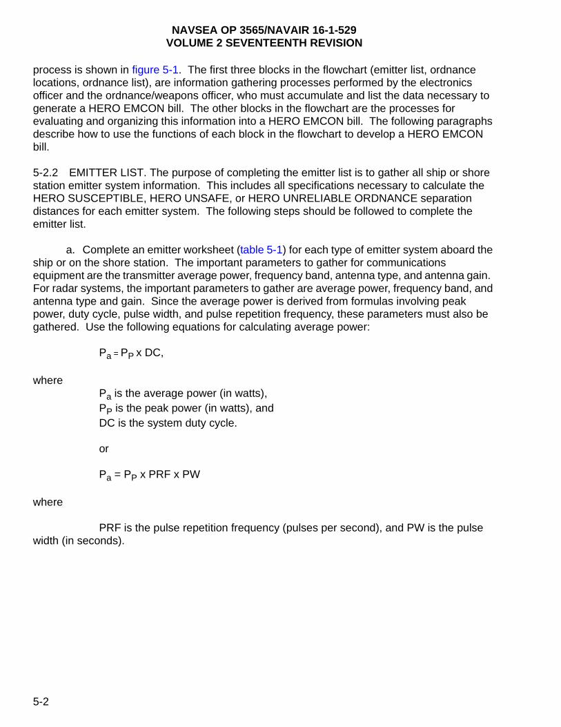
NAVSEA OP 3565/NAVAIR 16-1-529VOLUME 2 SEVENTEENTH REVISION
process is shown in figure 5-1. The first three blocks in the flowchart (emitter list, ordnance locations, ordnance list), are information gathering processes performed by the electronics officer and the ordnance/weapons officer, who must accumulate and list the data necessary to generate a HERO EMCON bill. The other blocks in the flowchart are the processes for evaluating and organizing this information into a HERO EMCON bill. The following paragraphs describe how to use the functions of each block in the flowchart to develop a HERO EMCON bill.
5-2.2 EMITTER LIST. The purpose of completing the emitter list is to gather all ship or shore station emitter system information. This includes all specifications necessary to calculate the HERO SUSCEPTIBLE, HERO UNSAFE, or HERO UNRELIABLE ORDNANCE separation distances for each emitter system. The following steps should be followed to complete the emitter list.
a. Complete an emitter worksheet (table 5-1) for each type of emitter system aboard the ship or on the shore station. The important parameters to gather for communications equipment are the transmitter average power, frequency band, antenna type, and antenna gain. For radar systems, the important parameters to gather are average power, frequency band, and antenna type and gain. Since the average power is derived from formulas involving peak power, duty cycle, pulse width, and pulse repetition frequency, these parameters must also be gathered. Use the following equations for calculating average power:
Pa = PP x DC,
wherePa is the average power (in watts),PP is the peak power (in watts), andDC is the system duty cycle.
or
Pa = PP x PRF x PW
where
PRF is the pulse repetition frequency (pulses per second), and PW is the pulse width (in seconds).
5-2

NAVSEA OP 3565/NAVAIR 16-1-529VOLUME 2 SEVENTEENTH REVISION
Figure 5-1. HERO EMCON Bill Development
5-3
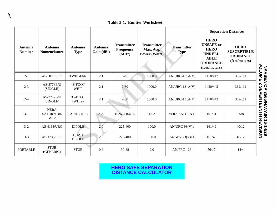
NA
VS
EA
OP
3565/NA
VA
IR 16-1-529
VO
LU
ME
2 SE
VE
NT
EE
NT
H R
EV
ISIO
N
5-4
Separation Distances
HERO UNSAFE or
HERO UNRELI-
ABLE ORDNANCE (feet/meters)
HERO SUSCEPTIBLE
ORDNANCE(feet/meters)
) 1450/442 362/111
) 1450/442 362/111
) 1450/442 362/111
B 101/31 25/8
1 161/49 40/12
1 161/49 40/12
56/17 14/4
Table 5-1. Emitter Worksheet
AntennaNumber
Antenna Nomenclature
AntennaType
AntennaGain (dBi)
Transmitter Frequency
(MHz)
Transmitter Max. Avg.
Power (Watts)
TransmitterType
2-1 AS-3870/SRC TWIN-FAN 2.1 2-9 1000.0 AN/URC-131A(V
2-3AS-3773B/U
(SINGLE)18-FOOT
WHIP2.1 7-30 1000.0 AN/URC-131A(V
2-4AS-3772B/U
(SINGLE)35-FOOT (WHIP)
2.1 2-30 1000.0 AN/URC-131A(V
3-1NERA
SATURN Bm MK2
PARABOLIC 23.9 1626.5-1646.5 13.2 NERA SATURN
3-2 AS-4163/URC DIPOLE 2.0 225-400 100.0 AN/URC-93(V)
3-3 AS-1735/SRCQUAD
DIPOLE2.0 225-400 100.0 AN/WSC-3(V)1
PORTABLESTUB
(GENERIC)STUB 0.9 30-88 2.0 AN/PRC-126
HERO SAFE SEPARATION DISTANCE CALCULATOR

NAVSEA OP 3565/NAVAIR 16-1-529VOLUME 2 SEVENTEENTH REVISION
NOTE
When using the latter formula, the PW and PRF should be calculated from radar modes that produce the highest average power.
For shore stations, each antenna should be correlated to a building number in order to identify specific locations. For ships, each entry should list the designated antenna number for each antenna.
b. Once the system characteristics are obtained, calculate the HERO SUSCEPTIBLE, HERO UNSAFE, or HERO UNRELIABLE ORDNANCE separation distances.
NOTE
When calculating distances, use the lowest frequency in the band to obtain the correct value for each emitter system. For frequencies below 2 MHz, use the highest frequency.
Since the calculated distances will be compared to the actual distances between each antenna and the various ordnance locations, this process allows for the identification of potential HERO problems.
c. The emitter worksheet, table 5-1, should be retained for additions, deletions, and historical purposes. It will be submitted as part of the HERO pre-survey data package (see chapter 6) to the Naval Surface Warfare Center, Dahlgren Division (NSWCDD) (Code Q52) to provide HERO technical personnel with the required information for determining future instrumented survey requirements.
5-2.3 ORDNANCE LIST AND LOCATION IDENTIFICATION. The purpose of listing and identifying the location of the electrically initiated ordnance items present is to determine their HERO classification and to make note of RF concerns at their respective locations. Ordnance locations shall include all locations that are represented in the stockpile-to-deployment sequence for a specific ordnance item; i.e., storage areas, assembly areas, transportation routes, staging areas, and deployment locations. The data sheets in volume 3 provide HERO classifications and susceptibility criteria for ordnance containing electrically initiated devices (EID’s). Items containing EID’s that do not have a data sheet or HERO classification are either components or subsystems of all-up rounds (AUR’s) or untested ordnance, and are to be treated as HERO UNSAFE or HERO UNRELIABLE ORDNANCE until a HERO status is provided by the Naval Ordnance Safety and Security Activity (NOSSA). The following steps should be performed to complete the ordnance list and location identification:
a. Complete an ordnance location worksheet (table 5-2), listing all of the ordnance items by Navy Ammunition Logistic Code (NALC) or Department of Defense Identification Code (DODIC) and the location where these items are present. When completed, the worksheet will provide a description of ordnance presence, handling, loading/unloading, storage, and assembly areas.
5-5

NAVSEA OP 3565/NAVAIR 16-1-529VOLUME 2 SEVENTEENTH REVISION
For ships, locations listed may include the flight deck, hangar, vertical replenishment (VERTREP) stations, Close-in Weapon System (CIWS) mounts, ready service locker locations, and NATO SEASPARROW Missile System (NSSMS) launchers, and magazines and build-up rooms that open to the weather decks. (Areas such as lower magazines and below decks build-up rooms aboard ship need not be included on the ordnance location worksheet.) Ordnance locations should be identified on the ship’s topside diagrams.
Shore station ordnance locations may include the combat aircraft loading area (CALA), arm/de-arm areas, red label areas, hot cargo areas, build-up areas, ordnance loading piers, ready service locker locations, assembly buildings, and magazine areas. Ordnance locations, as well as the ordnance transportation routes, should be identified on scaled drawings and included as part of the HERO pre-survey data package.
b. Once all the ordnance items and their locations have been identified, refer to the data sheets in volume 3 to determine their HERO status. These ordnance items will be the subject of the HERO EMCON Bill, and their locations will be compared to the locations of the emitter systems listed as described in paragraph 5-2.2 above. Also ordnance items that are components of AUR’s, or HERO untested ordnance items; i.e., items that contain EID’s and are not listed in volume 3, are to be treated as HERO UNSAFE or HERO UNRELIABLE ORDNANCE until a new HERO status is established by NOSSA. For those items identified as HERO SAFE ORDNANCE, no specific HERO EMCON is required.
NOTE
In all instances, the general HERO requirements outlined in paragraph 7-3 must be observed.
5-2.4 COMPARE SAFE SEPARATION DISTANCES FROM ORDNANCE LOCATIONS. Once emitters and ordnance as well as their locations have been identified, use the ship-scaled topside diagram or station topographical map to determine the distances between the antennas and the various ordnance locations. Incorporate this information, as well as the safe separation distances from table 5-1 for each emitter system, into table 5-3 to identify the emitter systems requiring HERO EMCON for each ordnance location.
5-6

NAVSEA OP 3565/NAVAIR 16-1-529VOLUME 2 SEVENTEENTH REVISION
Table 5-2. Ordnance Location (L) Worksheet
NALCHEROStatus
Ordnance Locations
CIWSMount
21
CIWSMount
22
NSSMSLauncher
HangarDeck
FlightDeck
L1 L2 L3 L4 L5
A676 SUSC. X X
A659 SUSC. X X
M161 SUSC. X X
PE43 SUSC. X
MF64 SAFE X X
5-7

NA
VS
EA
OP
3565/NA
VA
IR 16-1-529
VO
LU
ME
2 SE
VE
NT
EE
NT
H R
EV
ISIO
N
5-8
cations (L)
ance Locations (feet)
L4 L5
275 300
285 310
Table 5-3. Emitter Safe Separation Distances vs. Distance to Ordnance Lo
Actual Distance to Ordn
Emitter SystemCalculated Safe Separation Distances
UNSAFE/SUSCEPTIBLE (feet) L1 L2 L3
AN/URT-23D(Ant. 2-1)
3624/362 80 150 200
AN/URT-23D(Ant. 2-2)
3624/362 90 160 210
AN/URT-80(Ant. 3-5)
49/11 95
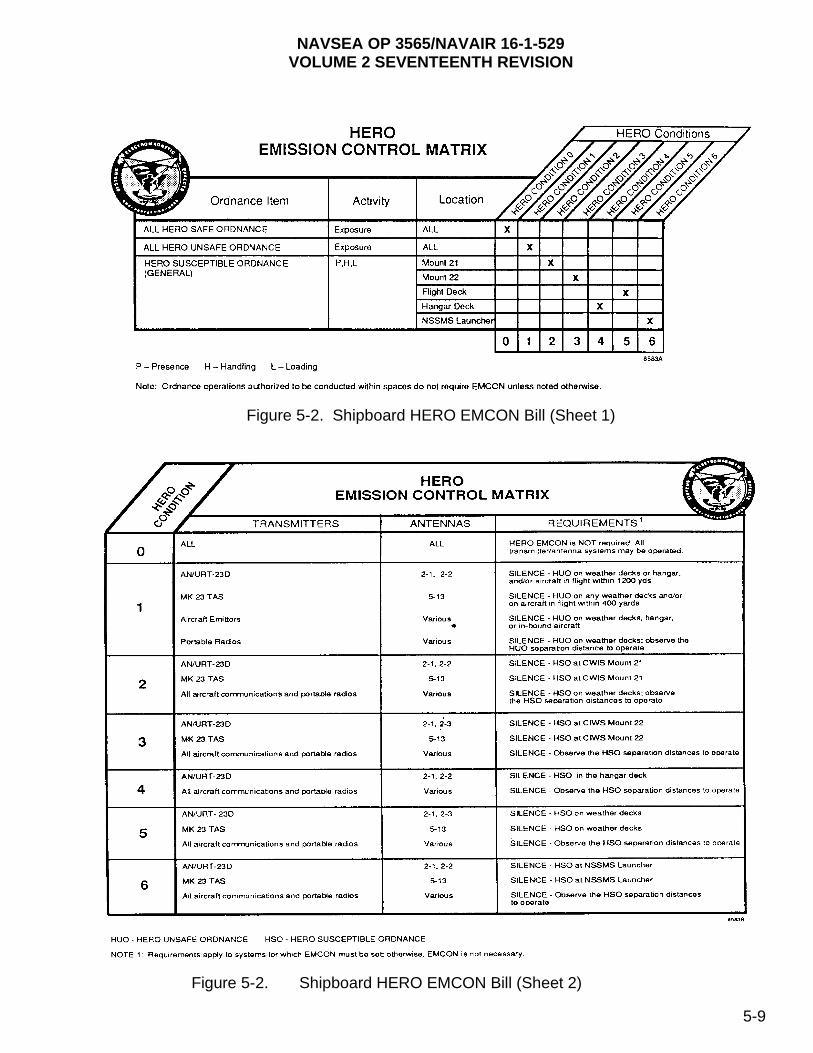
NAVSEA OP 3565/NAVAIR 16-1-529VOLUME 2 SEVENTEENTH REVISION
Figure 5-2. Shipboard HERO EMCON Bill (Sheet 1)
Figure 5-2. Shipboard HERO EMCON Bill (Sheet 2)
5-9

NAVSEA OP 3565/NAVAIR 16-1-529VOLUME 2 SEVENTEENTH REVISION
In those instances where the HERO UNSAFE, HERO UNRELIABLE, or HERO SUSCEPTIBLE ORDNANCE safe separation distances for an emitter exceed the distance to a specific ordnance location, HERO EMCON (radio silence) will be necessary. This HERO EMCON condition must be imposed when conducting ordnance operations involving HERO UNSAFE, HERO UNRELIABLE or HERO SUSCEPTIBLE ORDNANCE. Different locations may have identical HERO conditions as a result of this process; i.e., the same emitter systems will be restricted by HERO EMCON imposed in more than one location. In these instances, the same HERO EMCON condition can be combined to apply to more than one location in order to limit the number of HERO conditions imposed. For example, HERO CONDITION 2 may apply to both CIWS Mount 21 and CIWS Mount 22.
5-2.5 GENERATION OF HERO EMCON BILL. Once the HERO EMCON conditions have been identified, a HERO instruction, or HERO EMCON bill, can be written. Appendix E provides a sample HERO instruction for ships and shore facilities. The HERO EMCON bills should be incorporated into these HERO instructions. The HERO EMCON bill provides distinct HERO procedures for specific ordnance and their locations. Figure 5-2 provides an example of a shipboard bill in matrix format. The example shown in figure 5-2 tabulates the results of the procedure outlined in paragraph 5-2.4, above: specific locations of concern, identified in table 5-3, are assigned HERO conditions which identify the emitters requiring EMCON. To achieve this, figure 5-2 is completed first by identifying both the type of ordnance and the location of concern. Next, the HERO conditions in table 5-3 are established, outlining the procedures for setting HERO EMCON at the various locations of concern. On the matrixes, only the ordnance items’ locations and the antennas of concern are listed as part of the HERO EMCON bill.
NOTE
Ships should not expose HERO UNSAFE/UNRELIABLE ORDNANCE on the weather decks. However, a HERO UNSAFE/UNRELIABLE ORDNANCE condition is included in the ships’ HERO EMCON bill to provide for emergency contingencies (such as inbound and outbound joint-service aircraft or Allied, combined, and coalition forces) with unknown ordnance aboard, or when ordnance that is HERO SAFE or HERO SUSCEPTIBLE is rendered HERO UNSAFE or HERO UNRELIABLE because of an accident or incident.
5-2.5.1 Results of HERO EMCON Bill. Once established, appropriate separation distances must be maintained between fixed emitter systems and inbound and outbound aircraft carrying HERO SUSCEPTIBLE, HERO UNSAFE, or HERO UNRELIABLE ORDNANCE. This process will result in the silencing of high frequency/very high frequency (HF/VHF) (2-80 MHz) communications and high-power search and fire control radars. Mobile and portable radios at each ordnance location will be affected by the separation distances imposed between HERO SUSCEPTIBLE, HERO UNSAFE, or HERO UNRELIABLE ORDNANCE and the radios.
5-2.5.2 Effects on Fire Control Radars and Satellite Communication (SATCOM) Systems. Although the distances between ordnance locations and fire control radars and satellite communication (SATCOM) systems are generally less than the separation distances required for HERO SUSCEPTIBLE ORDNANCE, restrictions are often unnecessary. These systems cannot (or do not) directly illuminate ordnance evolutions with main beam radiation due to
5-10
NAVSEA OP 3565/NAVAIR 16-1-529VOLUME 2 SEVENTEENTH REVISION
radiation hazard (RADHAZ) cutouts or structural blockage. After careful review of cutout zones and blockage, the electronics maintenance office (EMO) and CSO may eliminate these systems from the HERO EMCON bill.
5-2.5.3 HERO Zones. Since shore stations are larger than ships and generally have more emitter systems and ordnance locations, a station may be divided for HERO EMCON bill development purposes, into several parts called HERO zones. Creating zones assists in managing the number of emitters that must be silenced during ordnance evolutions, and reducing the number of HERO conditions. Ordnance locations that are similar in type, geography and EMCON restrictions are grouped, or zoned, into localized areas in order to simplify the application of HERO EMCON. Roadways and landmarks can be used to designate the zone perimeter. Some typical examples of these zones are:
a. Ordnance magazine areas, consisting of storage magazines and missile, bomb, torpedo assembly areas.
NOTE
This area should be maintained as a “safe haven” where HERO UNSAFE or HERO UNRELIABLE, untested, and retrograde ordnance are stored. No transmissions should be permitted in this area.
b. Runway and hangar areas, including Combat Aircraft Loading/Parking Area (CALA), arm/de-arm, hot cargo, and red label areas, hangars and parking aprons.
NOTE
An exception is made for hangars that are separated from the runway where helicopters or special aircraft are maintained. This area should be zoned separately.
c. Administrative areas through which ordnance is transported to/from runways, magazine areas, or gates.
5-3. HERO EMCON BILL UPDATE OR MODIFICATION
5-3.1 Changes to either the emitter configuration or the ordnance configuration of a ship or shore station can necessitate the update or modification of an existing HERO EMCON bill. Figure 5-3 illustrates a flowchart for adding ordnance or emitters to the existing HERO EMCON bill. The process uses many of the same preliminary steps used when developing an EMCON bill, outlined in paragraph 5-2.
NOTE
The deletion of either ordnance or emitters is simply a matter of removing them from the existing HERO EMCON bill.
5-11

NAVSEA OP 3565/NAVAIR 16-1-529VOLUME 2 SEVENTEENTH REVISION
5-3.2 NEW ORDNANCE ITEMS. When a new ordnance item is received onboard, identify its location and classification as described in paragraph 5-2.3 to determine if the existing HERO EMCON bill needs modifications. If the item is percussion-initiated, non-explosive, or HERO SAFE ORDNANCE, there will be no EMCON requirements. If the item is HERO SUSCEPTIBLE, HERO UNSAFE, or HERO UNRELIABLE ORDNANCE, match its location to the location descriptions and specific conditions and procedures provided in the existing HERO EMCON bill. Also, the new ordnance item should be added to table 5-2, “Ordnance Location Worksheet” for future tracing purposes.
Figure 5-3. Ordnance and Emitter Configuration Changes
5-12
NAVSEA OP 3565/NAVAIR 16-1-529VOLUME 2 SEVENTEENTH REVISION
Similarly, when ordnance is relocated in an additional area, evaluate the ordnance location and add results to the HERO EMCON bill under the new location.
5-3.3 NEW EMITTER SYSTEMS. The guidance in this paragraph applies to new emitter systems as well as relocated or upgraded existing emitter systems. Add relocated or upgraded emitter systems to an existing HERO EMCON bill when system parameter changes (e.g., power or gain increases) result in changes to the appropriate separation distances. As discussed in paragraph 5-2.4, first assess whether the emitter’s HERO separation distances encompass the ordnance locations outlined in the existing HERO EMCON bill. See paragraph 5-2.2 for guidance when calculating safe separation distances for HERO SUSCEPTIBLE, HERO UNSAFE, or HERO UNRELIABLE ORDNANCE. Once the safe separation distance has been assessed, and the antenna location has been identified, these distances can be compared with the distances from known ordnance locations, outlined in table 5-3 or in the existing HERO EMCON bill.
If these distances do not encompass ordnance operations involving HERO SUSCEPTIBLE, HERO UNSAFE, or HERO UNRELIABLE ORDNANCE, there will be no HERO EMCON required. However, if the separation distances encompass any of these ordnance locations, as outlined in the existing HERO EMCON bill or table 5-3, EMCON restrictions (radio silence) must be incorporated into the existing HERO EMCON bill for the appropriate locations. First identify the locations listed under HERO UNSAFE, HERO UNRELIABLE, or HERO SUSCEPTIBLE ORDNANCE (general) conditions in the existing HERO EMCON bill, identify the locations listed under these conditions, then add the restriction to the appropriate HERO condition for each ordnance location of concern. Also, new emitter systems should be added to table 5-1 for future tracing purposes.
NOTE
The addition of new emitter systems on shore station must be submitted through Naval Facilities Engineering Command (NAVFACENGCOM) for fixed emitter installations or through NOSSA for mobile van emitter systems. Each shore facility has a NAVFACENGCOM division supporting that station. NAVFAC form 11010/31 Parts I and II (Request for Project Site Approval/Explosive Safety Certification) is used for submission and request, and can be found at the station Resident Officer in Charge of Construction (ROICC) or Public Works department. Instructions for completing NAVFAC form 11010/31 are contained in NAVFACINST 11010.45 (series). These requests are ultimately reviewed by NSWCDD (Code Q52) for HERO consequence. The results of the analysis are provided to the shore station with an addendum to the existing HERO EMCON bill.
5-4. HERO EMCON BILL WORKSHEET
5-4.1 Reproducible copies of the worksheets described in this chapter are located in appendix D for use in developing HERO EMCON bills.
5-13

NAVSEA OP 3565/NAVAIR 16-1-529VOLUME 2 SEVENTEENTH REVISION
5-5. JOINT OPERATIONS OR EXERCISES HERO GUIDANCE
5-5.1 The Joint Spectrum Center (JSC) has developed a tool to aid the Warfighter in making critical HERO decisions for embarked forces’ ordnance and emitters used in joint-service operations or exercises onboard U. S. Navy ships. The primary purpose of the Joint Operations E3 Risk Assessment Database (JOERAD) is to provide operational commanders and planners with the necessary information to safely and efficiently manage the conflict between any introduced ordnance and the radio frequency emitters employed in an integrated joint operation or exercise. With this information, the Warfighter can make informed decisions regarding the use or restriction of certain emitters and ordnance items.
5-5.2 JOERAD was not developed to replace a ship’s existing HERO EMCON Bill or instrumented HERO Survey, but to work in conjunction with the ship’s current HERO EMCON Bill and provide any of the additional information needed to resolve the conflict between ordnance and emitters, which are not currently addressed. JOERAD’s output is a HERO Impact Assessment, which addresses safety concerns for the embarked forces’ emitters and ordnance. In the event of conflicts between the JOERAD HERO Impact Assessment and the guidance provided in the ship’s HERO EMCON bill, the ship’s HERO EMCON bill shall take precedence.
5-5.3 JOERAD is ready for distribution to all operating forces. It may be obtained by contacting the JSC (J5) at Commercial (410) 293-4957 or DSN 281-4957, or by visiting the JSC website: http://www.jsc.mil, using the E3 Engineering Support link, and filling out the software request form. JOERAD is available to U. S. Military, U. S. Government, and their supporting contractors.
5-14

NAVSEA OP 3565/NAVAIR 16-1-529VOLUME 2 SEVENTEENTH REVISION
CHAPTER 6
HERO SURVEY
6-1. GENERAL
A Hazards of Electromagnetic Radiation to Ordnance (HERO) survey provides actual measurements of radio-frequency (RF) electromagnetic (EM) fields, as well as a more detailed look at the operational environment. In many instances, data gathered by the survey will alleviate some restrictions imposed by this manual. This chapter describes the survey process. It explains when and how to request a survey, cites specific data requirements that the activity to be surveyed must provide as input for the pre-survey analysis, describes the on-site procedure, and discusses the content of the survey report.
The electromagnetic environments (EME’s) of ships and shore facilities change with new/modified radar, electronic warfare, communications, and navigation transmitter installations. Changes may also occur to ordnance configuration, inventories, and operations.
6-1.1 WHEN TO REQUEST A SHIPBOARD HERO SURVEY. The Naval Sea Systems Command (NAVSEASYSCOM) requires ships to revise HERO Emission Control (EMCON) bills or to request a new HERO survey if one or more of the following apply:
a. The ship has no previous HERO survey or existing HERO EMCON bill,
b. The most recent HERO survey was performed more than five years ago and/or the current HERO EMCON bill does not contain specific EMCON procedures to be implemented,
c. Emitter systems have been added or relocated since the last survey,
d. Emitter systems have been upgraded as a result of a Ship Alteration (SHIPALT) or Ordnance Alteration (ORDALT),
e. Ordnance handling/loading/storage locations and/or procedures have changed since the last survey,
f. New ordnance items which are HERO UNSAFE, HERO UNRELIABLE, or HERO SUSCEPTIBLE have been added to the inventory list and are not addressed in the current version of NAVSEA OP 3565 or HERO survey report,
g. The ship’s mission statement has changed requiring the ship to support new aircraft not addressed in the current HERO survey report,
h. The ship has experienced a HERO-related ordnance incident and needs assistance in resolving ordnance safety issues.
6-1

NAVSEA OP 3565/NAVAIR 16-1-529VOLUME 2 SEVENTEENTH REVISION
6-1.2 HERO instrumented surveys requested by individual ships may not always be required. Surveys can only be scheduled after pertinent technical information has been reviewed by Naval Ordnance Safety and Security Activity (NOSSA) Indian Head (Code N84) and Naval Surface Warfare Center, Dahlgren Division (NSWCDD) (Code Q52) personnel. In many cases, current survey reports (and HERO EMCON bills) can be updated through specific line item pen-and-ink changes provided via official Naval correspondence.
6-1.3 HERO SURVEY TEAMS. NOSSA sponsors HERO survey teams that are trained and equipped to perform on-site instrumented surveys of the EME in ordnance operation areas. Survey teams take measurements of the EME in ordnance handling areas and along transportation routes and compare the data to ordnance item maximum allowable environments (MAE’s) to determine the specific HERO safety measures required for handling, storing, and transporting ordnance items in these areas.
6-1.4 HERO SHORE SURVEY PERIODICITY REQUIREMENTS. NOSSA, with input from NSWCDD, has reviewed ways of reducing the overall cost of HERO surveys while still maintaining the appropriate levels of safety. As a result, NOSSA established a new HERO survey periodicity for shore facilities as follows:
a. Five (5) Year Cycle - High transmitter density (population) with frequent upgrades and high-intensity ordnance operations. These facilities constantly undergo changes to their transmitter/antenna systems and ordnance facilities/operations. These changes are tracked by NSWCDD through the Naval Facilities Command (NAVFAC) site approval process. Some of these facilities are involved in the Base Realignment and Closure (BRAC) program.
b. Seven (7) Year Cycle - Moderate transmitter density and a stable, moderate intensity of ordnance operations. These facilities have some changes to the transmitter and antenna systems or ordnance operations that are submitted through the NAVFAC site approval process.
c. Ten (10) Year Cycle - Stable, low-density transmitter and ordnance population. These facilities maintain consistent operation with very few changes. Some of these facilities are Air Force, Army, and Navy reserve units that are very limited or restricted in the use of weapons.
6-1.4.1 NOSSA and NSWCDD personnel have reviewed past survey reports and transmitter site approval data in order to determine a periodicity for the activities. The results of this review are published in appendix E, which lists Navy and Marine Corps activities and shows the periodicity and the date for the next scheduled survey. The periodicity designated to a facility may change as a result of changes in its HERO posture, i.e., transmitter/antenna or ordnance operation changes. Generally, the information obtained during a HERO survey indicates to a facility’s future periodicity. Periodicity changes, if warranted, will be reflected in the facility’s HERO survey report as well as appendix E. It is emphasized, however, that the periodicity schedule provided in appendix E is based on emitters and ordnance as recorded during the last HERO survey. If any changes occur in emitter power output, frequency of the emitters, or there are any changes in the type of ordnance handled, a survey or engineering analysis may be required sooner than the scheduled periodicity date.
6-2
NAVSEA OP 3565/NAVAIR 16-1-529VOLUME 2 SEVENTEENTH REVISION
6-1.4.2 Shore facilities, including all tenant commands, that store, transfer, or use minimal amounts of ordnance containing electrically initiated devices (EID’s) or use only percussion-initiated ordnance may apply for a waiver of HERO survey requirements. If approved, the waiver exempts the facility from HERO surveys for five years. NOSSA may grant a facility two consecutive waivers (10 years), at which time a physical survey must occur to re-establish the facility’s baseline configuration. Facilities using only percussion-initiated ordnance may continue to apply for waivers. If the mission of the facility or any of the tenant commands changes to include operations involving ordnance containing EID’s, then the waiver is voided and the facility must request a HERO survey. The existence of a waiver does not exempt the facility from maintaining a HERO instruction.
6-1.5 THE HERO SURVEY PROCESS. NOSSA survey teams perform HERO surveys in accordance with policies set forth in OPNAVINST 8020.14/MCO P8020.11 (series) and NAVSEAINST 8020.7 (series). The survey process in initiated by a survey request from a ship or shore activity. The survey team performs an analysis of the data provided by the requesting activity and develops a plan for conducting an instrumented survey. An on-site survey is conducted; the results are analyzed; and a detailed report is developed. The report provides survey findings, analysis results, conclusions, and recommendations tailored to the command. Experience has shown that surveys result in more efficient use of ordnance areas and decreased impact on communication, radar, or other facilities.
6-2. REQUEST
Ships or shore activities desiring a HERO survey shall submit a request to NOSSA (Code N84), Bldg. D-323, Suite 108, 3817 Strauss Ave., Indian Head, MD 20640-5151. An information copy of the survey request shall be forwarded to Commander, NSWCDD (Q52/Charles Denham), 5493 Maple Road, Suite 287, Dahlgren, VA 22448-5153. The request shall identify a specific point of contact with a DSN and commercial telephone number. Informal communication regarding the HERO survey process may be established with NOSSA (Code N84), DSN 354-6082 or commercial (301) 744-6082, or NSWCDD (Code Q52), DSN 249-3444 or commercial (540) 653-3444.
6-3. PRE-SURVEY REQUIREMENTS
When a HERO survey request has been received and acknowledged, the most complete and accurate data available must be provided to the HERO survey team by the requesting activity. Pre-survey data contribute significantly to an accurate, effective, and expeditious survey result. Figure 6-1 is a checklist of pre-survey data required for a HERO survey. The following paragraphs discuss requirements expected to be completed by the requesting activity.
6-3.1 Provide up-to-date station maps or ship topside drawings, in AUTOCAD or equivalent format, annotated to show:
a. Ordnance storage areas,
b. Ordnance assembly/handling areas,
c. Ordnance transportation routes, and
d. Specific transmitters and accurate transmitting antenna locations.
6-3
NAVSEA OP 3565/NAVAIR 16-1-529VOLUME 2 SEVENTEENTH REVISION
6-3.2 Identify the Ordnance/Weapons Officer by name and provide a telephone number. List all ordnance systems and items and their Department of Defense Identification Code/Naval Ammunition Logistic Code (DODIC/NALC). Do not list quantities. Indicate what ordnance is handled at each location listed in 6-3.1a and b.
6-3.3 Identify the communications officer and electronic warfare officer (EWO) by name and provide their telephone numbers. List all transmitters and antennas identified by military nomenclature or, if appropriate, manufacturer and model. All transmitter and antenna facilities must be cited, including fixed, mobile, relay, etc. Provide operating parameters such as average power in watts, frequency range in megahertz, and antenna gain in decibels referenced to an isotropic antenna (dBi). A format such as the one shown in figures 6-2 or 6-3 is recommended for reporting this data.
6-3.4 Provide information relating to anticipated changes in ordnance items, storage sites, or transportation routes.
6-4

NAVSEA OP 3565/NAVAIR 16-1-529VOLUME 2 SEVENTEENTH REVISION
Data items should be checked off, as available.
( ) 1. Ship Drawings/Station Map(s) (In AUTOCAD or equivalent format marked to show):
a. Ordnance storage locations.
b. Ordnance assembly/handling locations.
c. Ordnance transportation routes.
d. Transmitter and antenna locations.
e. Arming/dearming areas.
( ) 2. Ordnance Information
a. Weapons/Ordnance Officer’s name and telephone number (commercial and DSN).
b. A list of all ordnance items and systems.
c. DODIC/NALC or manufacturer’s part number.
d. Indicate which ordnance is assembled/handled/present at the locations listed in 1a and 1b.
( ) 3. Emitter Information
a. Communications Officer’s and Electronics Warfare Officer’s telephone numbers (commercial and DSN).
b. Transmitter identification (for all transmitters; i.e., fixed, mobile, and portable).
c. Average power output.1
d. Frequency range.
e. Antenna identification/type and nomenclature.
f. Antenna gain in dBi (dB reference to an isotropic antenna) or dBd (dB reference to a ½-wave dipole antenna).
1For radars, provide:
a. Peak powerb. Pulse durationc. Pulse repetition frequency
FIGURE 6-1. Checklist for HERO Pre-Survey Data (Sheet 1 of 2)
6-5
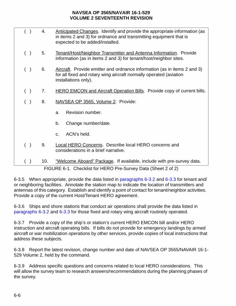
NAVSEA OP 3565/NAVAIR 16-1-529VOLUME 2 SEVENTEENTH REVISION
FIGURE 6-1. Checklist for HERO Pre-Survey Data (Sheet 2 of 2)
6-3.5 When appropriate, provide the data listed in paragraphs 6-3.2 and 6-3.3 for tenant and/or neighboring facilities. Annotate the station map to indicate the location of transmitters and antennas of this category. Establish and identify a point of contact for tenant/neighbor activities. Provide a copy of the current Host/Tenant HERO agreement.
6-3.6 Ships and shore stations that conduct air operations shall provide the data listed in paragraphs 6-3.2 and 6-3.3 for those fixed and rotary wing aircraft routinely operated.
6-3.7 Provide a copy of the ship’s or station’s current HERO EMCON bill and/or HERO instruction and aircraft operating bills. If bills do not provide for emergency landings by armed aircraft or war mobilization operations by other services, provide copies of local instructions that address these subjects.
6-3.8 Report the latest revision, change number and date of NAVSEA OP 3565/NAVAIR 16-1-529 Volume 2, held by the command.
6-3.9 Address specific questions and concerns related to local HERO considerations. This will allow the survey team to research answers/recommendations during the planning phases of the survey.
( ) 4. Anticipated Changes. Identify and provide the appropriate information (as in items 2 and 3) for ordnance and transmitting equipment that is expected to be added/installed.
( ) 5. Tenant/Host/Neighbor Transmitter and Antenna Information. Provide information (as in items 2 and 3) for tenant/host/neighbor sites.
( ) 6. Aircraft. Provide emitter and ordnance information (as in items 2 and 3) for all fixed and rotary wing aircraft normally operated (aviation installations only).
( ) 7. HERO EMCON and Aircraft Operation Bills. Provide copy of current bills.
( ) 8. NAVSEA OP 3565, Volume 2: Provide:
a. Revision number.
b. Change number/date.
c. ACN’s held.
( ) 9. Local HERO Concerns. Describe local HERO concerns and considerations in a brief narrative.
( ) 10. “Welcome Aboard” Package. If available, include with pre-survey data.
6-6

NA
VS
EA
OP
3565/NA
VA
IR 16-1-529
VO
LU
ME
2 SE
VE
NT
EE
NT
H R
EV
ISIO
N
6-7
NOT ate.
7 8
TNo
ntennain (dBi)
Antenna type
E: If transmitter is single-side band (SSB) or does not have continuous carrier wave, please indic
FIGURE 6-2. Communications Transmitter/Antenna Characteristics
1 2 3 4 5 6
ransmitter menclature
Location (Frame #/Site)
Frequency (MHz)
AveragePower (W)
Antenna Nomenclature
Location(Frame #/Site)
AGa

NA
VS
EA
OP
3565/NA
VA
IR 16-1-529
VO
LU
ME
2 SE
VE
NT
EE
NT
H R
EV
ISIO
N
6-8
7 8
AntennaGain (dBi)
AntennaLocation
*This information not required if average power is shown in column 4 and labeled as such.
FIGURE 6-3. Radar Transmitter/Antenna Characteristics
1 2 3 4 5 6
Transmitter LocationFrequency
(MHz)Peak/Average
Power (W)
PulseRepetitionFrequency
(PPS)*
PulseWidth (µs)*
Location

NAVSEA OP 3565/NAVAIR 16-1-529VOLUME 2 SEVENTEENTH REVISION
6-3.10 If the command routinely provides a ship or station information package, include that data with the pre-survey material. Information regarding local military and commercial accommodations for survey team personnel should also be included.
6-3.11 The on-site survey will be more efficient if the following are provided:
a. A memorandum requesting the cooperation of all command departments, resident squadrons, tenant/host commands, and adjacent facilities advising them of the survey and its purpose;
b. Security and visit clearance for the HERO survey team to all appropriate agencies;
c. Dedicated on-site transportation such as a pickup or van, with driver for the survey team and their equipment;
d. Access for the survey team to all ordnance, transmitter, and antenna locations; and
e. Authorization for the survey team to photograph antenna and measurement sites (sensitive and classified material will be protected).
6-4. PROCEDURES
6-4.1 ARRIVAL. Upon arrival, the survey team leader will conduct an arrival conference to brief ship/station personnel on the survey process and answer any questions they may have. Along with the survey team, participants in the conference should include the weapon or ordnance officer, safety officer, ground electronics maintenance (or ship’s electronics material) officer, communications officer, the survey coordinator, and representatives from tenant commands. The conference agenda should address the survey plan, special concerns, and a review of ordnance and electronics emission data. The survey team should be given a familiarization tour of the ship or station, with particular emphasis on the electronic emitter and ordnance handling arming/dearming areas, storage sites, and transportation routes. The conference and tour allows the survey team to identify any potential ordnance/emitter hazards that may have been overlooked in the preparation of the pre-survey materials.
6-4.2 MEASUREMENT OF EME. The survey team will carry out the survey plan by measuring the EME in a greater-to-lesser order of potential hazards. The team will assess measurement results based on current and future ordnance operations. Prior to survey team departure, the team leader will brief the Commanding Officer (CO) on preliminary significant findings.
6-4.3 REPORT. The HERO survey team leader is responsible for developing a detailed written report. It sets forth the field survey results along with an analysis of measurements with relevant technical data. Conclusions and recommendations regarding the use of transmitters during ordnance operations are presented with supporting documentation. Recommendations for local development of a HERO EMCON bill are also provided.
6-9
NAVSEA OP 3565/NAVAIR 16-1-529VOLUME 2 SEVENTEENTH REVISION
6-4.4 SAMPLE HERO INSTRUCTIONS. For both ship and shore facilities, the HERO survey report will contain an updated sample HERO instruction to be implemented upon command review and approval. Ships will also be provided with HERO EMCON matrixes to be posted at the appropriate watch stations.
6-10
NAVSEA OP 3565/NAVAIR 16-1-529VOLUME 2 SEVENTEENTH REVISION
CHAPTER 7
HERO REQUIREMENTS DURING ORDNANCE OPERATIONS
7-1. INTRODUCTION
The process for reducing potential electromagnetic radiation (EMR) hazards through proper ordnance handling operations is covered in this chapter; specifically, maintaining appropriate separation distances between ordnance and transmitting antennas, covering ordnance electrical connectors, transporting ordnance in sealed, all-metal containers, etc. This chapter also discusses how to determine the Hazards of Electromagnetic Radiation to Ordnance (HERO) classification of an ordnance item as well as the general HERO requirements for shore facility and shipboard ordnance operations. The general HERO requirements apply to all ordnance items containing electrically initiated devices (EID’s) regardless of their HERO classification. The intent of this chapter is to provide specific guidance for operations involving HERO SUSCEPTIBLE, HERO UNSAFE, and HERO UNRELIABLE ORDNANCE when such ordnance is exposed to electromagnetic environments (EME’s).
7-2. ORDNANCE HERO CLASSIFICATIONS
7-2.1 HOW TO DETERMINE HERO CLASSIFICATION. To determine the HERO classification of a particular ordnance item, first refer to figure 7-1 and then to table 1-1 of NAVSEA OP 3565/NAVAIR 16-1-529 Volume 3, which lists, by Department of Defense Identification Code (DODIC), Navy Ammunition Logistic Code (NALC), or National Stock Number (NSN), all ordnance items that have been evaluated for HERO. Table 1-1 of volume 3 also lists the HERO classification (HERO SAFE, HERO SUSCEPTIBLE, HERO UNSAFE, HERO UNRELIABLE) of each ordnance item containing EID’s. For ordnance items considered HERO SUSCEPTIBLE, HERO UNSAFE, or HERO UNRELIABLE ORDNANCE, it provides additional information about the item’s susceptibility to EME’s.
7-2.2 HOW TO USE HERO DATA. If the ordnance item is listed in table 1-1 of volume 3 as HERO SAFE ORDNANCE, then only the general HERO requirements given in paragraph 7-3 must be followed. If the ordnance item is listed as HERO SUSCEPTIBLE, HERO UNSAFE, or HERO UNRELIABLE ORDNANCE, then EME restrictions will be required in addition to the general HERO requirements of paragraph 7-3. Table 1-1 of volume 3 lists the item’s EID firing consequence (safety/reliability) and a hyperlink to the corresponding data sheet. The data sheet provides specific information about the HERO susceptibility of the ordnance item, including frequency, maximum allowable environment (MAE), and situations where the item is susceptible to EME’s. In some instances, the data sheet also provides procedures to mitigate potential HERO problems.
7-2.3 HERO UNSAFE OR HERO UNRELIABLE ORDNANCE. An ordnance item that contains an EID or an item whose EID status is unknown and is not listed in table 1-1 of volume 3 must be treated as HERO UNSAFE or HERO UNRELIABLE ORDNANCE and handled in accordance with the general guidance contained in this chapter for HERO UNSAFE or HERO UNRELIABLE ORDNANCE. Contact the Naval Ordnance Safety and Security
7-1
NAVSEA OP 3565/NAVAIR 16-1-529VOLUME 2 SEVENTEENTH REVISION
Activity (NOSSA) or the Naval Air Systems Command (NAVAIRSYSCOM) competency 4.9.5 for specific guidance related to HERO UNSAFE or HERO UNRELIABLE ORDNANCE.
7-2.3.1 Ordnance items normally classified as HERO SAFE or HERO SUSCEPTIBLE ORDNANCE can be degraded to HERO UNSAFE or HERO UNRELIABLE ORDNANCE during assembly, disassembly, or testing, or by subjecting the items to unauthorized conditions and operations. Care should be taken to ensure that such conditions and operations occur in a radio-frequency (RF)-free environment as defined in chapter 1. Examples of conditions leading to HERO UNSAFE or HERO UNRELIABLE ORDNANCE are:
a. Assembly or disassembly of ordnance systems such as those undergoing modification, repair, upkeep, parts exchange, strikedown, etc.;
b. Tests involving additional electrical connections to the ordnance system such as resistance checks, continuity checks, etc.;
c. Squibs, primers, blasting caps, impulse cartridges, and other EID’s having exposed leads or primer buttons that are unshielded and/or unfiltered, such as flash signals, igniters, tracking flares, etc., and have not been HERO-evaluated in these configurations;
d. Unshielded ordnance subassemblies such as rocket motors, warheads, exercise heads, fuzes, and
e. Damaged ordnance items that have internal components exposed, seams or joints that are no longer intact, or HERO shielding [such as barrier plates on 2.75-inch folding fin aircraft rocket (FFAR) launchers] breeched.
7-2.3.2 If the above conditions are encountered and exposure to EME’s cannot be avoided, HERO UNSAFE or HERO UNRELIABLE ORDNANCE can be protected by completely enclosing the item in a sealed, all-metal container.
NOTE
Ordnance items packaged in a wooden, cardboard, or plastic container or stacked on a metal pallet are not protected from the EME.
Further, HERO UNSAFE or HERO UNRELIABLE ORDNANCE shall only be removed from protective packaging in an EME that does not exceed the levels provided in chapter 2, figure 2-2. Such areas may be found below decks of ships or in buildings designed with electromagnetic (EM) shielding. HERO UNSAFE or HERO UNRELIABLE ORDNANCE shall not be permitted on the flight deck, the hangar deck, or any weather deck of ships unless appropriate emission control (EMCON) conditions are invoked. (See chapter 2.)
7-2
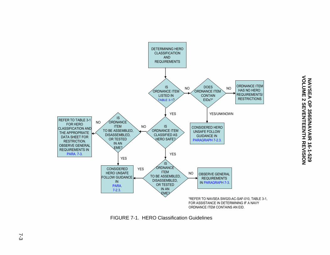
NA
VS
EA
OP
3565/NA
VA
IR 16-1-529
VO
LU
ME
2 SE
VE
NT
EE
NT
H R
EV
ISIO
N
7-3
ORDNANCE ITEM
HAS NO HERO
REQUIREMENTS/
RESTRICTIONS
.
N
0-AC-SAF-010, TABLE 3-1,
RMINING IF A NAVY
S AN EID.
FIGURE 7-1. HERO Classification Guidelines
CONSIDERED HERO
UNSAFE FOLLOW
GUIDANCE IN
PARAGRAPH 7-2.3.
IS
ORDNANCE ITEM
LISTED IN
TABLE 3-1?
CONSIDERED
HERO UNSAFE
FOLLOW GUIDANCE
IN
PARA.
7-2.3.
DETERMINING HERO
CLASSIFICATION
AND
REQUIREMENTS
DOES
ORDNANCE ITEM
CONTAIN
EIDs?*
IS
ORDNANCE ITEM
CLASSIFIED AS
HERO SAFE?
IS
ORDNANCE
ITEM
TO BE ASSEMBLED,
DISASSEMBLED,
OR TESTED
IN AN
EME?
OBSERVE GENERAL
REQUIREMENTS
IN PARAGRAPH 7-3
IS
ORDNANCE
ITEM
TO BE ASSEMBLED,
DISASSEMBLED,
OR TESTED
IN AN
EME?
REFER TO TABLE 3-1
FOR HERO
CLASSIFICATION AND
THE APPROPRIATE
DATA SHEET FOR
RESTRICTION.
OBSERVE GENERAL
REQUIREMENTS IN
PARA. 7-3.
NO NO
NO
NO
YES
YES
YES
YES
NO
YES/UNKNOW
*REFER TO NAVSEA SW02
FOR ASSISTANCE IN DETE
ORDNANCE ITEM CONTAIN
NAVSEA OP 3565/NAVAIR 16-1-529VOLUME 2 SEVENTEENTH REVISION
7-2.3.3 Unexploded ordnance (UXO) is considered to be HERO UNSAFE or HERO UNRELIABLE ORDNANCE. The detection equipment used to locate UXO (i.e., ground-penetrating radar, ground conductivity meters, etc.) may be capable of generating sufficient electromagnetic energy to cause inadvertent actuation of EID’s in UXO. Prior to commencing operations with UXO, contact NOSSA (Code N84) to determine the safety of the detection equipment. Contact NOSSA (Code N84) for specific guidance related to HERO UNSAFE or HERO UNRELIABLE ORDNANCE.
7-2.4 COMPONENTS OF ALL-UP ROUNDS (AUR’S). AUR’s that contain EID’s must be considered for HERO. Typically, HERO tests do not evaluate the individual components of an AUR separate from the AUR unless operational requirements dictate the need (e.g., blasting caps, ejector cartridges, and some bomb fuzes). Individual components that contain EID’s and are not listed in table 1-1 of volume 3 shall be considered HERO UNSAFE or HERO UNRELIABLE ORDNANCE and require EMCON during all ordnance operations involving these components. This general guidance may be tailored if specific information is known about the individual component configuration and its projected use within the Department of Defense (DoD). The following provide additional guidance for tailoring the EMCON requirements for individual components:
a. Presence of Components/Subassemblies (transportation/storage phase). Components/subassemblies shipped in sealed, all-metal containers or metal foil packages do not require HERO EMCON. The unopened container/packaging may be safely/reliably transported, handled, or stored in the typical shore facility/shipboard EME. See NAVSEA SW020-AC-SAF-010 for specific packaging or description of material composition of containers used for transporting and storing the item.
NOTE
The container/packaging must not be opened during this phase. Components/subassemblies that are shipped in non-metal containers or packages require HERO EMCON.
b. Removal of individual components/subassemblies from their containers, or packaging and assembly/disassembly of the components must be performed in an area designated for HERO UNSAFE or HERO UNRELIABLE ORDNANCE; otherwise, HERO EMCON is required.
c. Handling, removing, or installing components in subassemblies of AUR’s or assembly of AUR’s requires HERO EMCON.
d. Once all the components have been assembled or installed into the system, HERO guidance is based on the HERO classification of the resultant AUR. Refer to table 1-1 of volume 3 for HERO classification of the AUR.
7-3. GENERAL HERO REQUIREMENTS
The following general HERO requirements must be implemented when conducting operations with any ordnance item that contains EID's, regardless of the ordnance item’s HERO classification.
7-4
NAVSEA OP 3565/NAVAIR 16-1-529VOLUME 2 SEVENTEENTH REVISION
7-3.1 GENERAL HERO REQUIREMENTS FOR ORDNANCE OPERATIONS.
7-3.1.1 Comply strictly with authorized ordnance loading manuals and checklists.
7-3.1.2 Plan ordnance operations so that the ordnance has a minimal exposure to the EME.
7-3.1.3 Do not alter ordnance systems (ordnance item, electrical cables, etc.) unless NOSSA and/or NAVAIRSYSCOM have been contacted to determine the HERO impact of such alterations.
7-3.1.4 Do not allow electrical contacts, electrodes (primer buttons), or connector pins to touch any object capable of conducting EM energy during handling and loading operations. Objects capable of conducting EM energy include aircraft, launchers, hoists, bomb carts, bomb racks, cartridge breeches and connectors, tools, personnel, other cartridges, and cartridge actuated devices (CAD’s). Intentional contact with CAD primer buttons and connector pins that is not required to complete authorized handling and loading and/or unloading operations is prohibited.
7-3.1.5 Do not handle umbilical cables and cable connectors unnecessarily.
7-3.1.6 Do not make electrical connections to air-launched ordnance systems before the ordnance is racked to the aircraft unless:
a. procedures have been specifically authorized in the checklist or loading manual,
b. the appropriate HERO conditions for HERO UNSAFE or HERO UNRELIABLE ORDNANCE contained in the current HERO survey have been implemented, or
c. the HERO UNSAFE or HERO UNRELIABLE ORDNANCE safe separation distances provided in figure 2-2 are maintained between transmitting antennas and the ordnance operation. Electrical connections between aircraft and ordnance are the most likely entry paths for RF energy.
NOTE
Racking an ordnance item to the aircraft first and tightening the sway braces before making electrical connections reduces the amount of EM energy induced into the item’s internal circuitry.
7-3.1.7 Transport all HERO UNSAFE or HERO UNRELIABLE ORDNANCE in sealed, all-metal containers whenever possible.
NOTE
By definition, a pallet is not a container. Therefore, metal pallets shall not be considered all-metal containers.
7-3.1.8 Cover all open electrical connectors on ordnance items with non-shorting caps to prevent accidental contact with the pins of these connectors. The caps should be removed just prior to connector mating and reinstalled promptly upon connector unmating.
7-5
NAVSEA OP 3565/NAVAIR 16-1-529VOLUME 2 SEVENTEENTH REVISION
7-3.1.9 Do not expose the ordnance item’s internal wiring and firing circuits by assembling or disassembling the ordnance in an EME.
7-3.1.10 Test procedures that involve making electrical connections to the ordnance are permitted only if authorized by the loading manual or checklist.
7-3.1.11 Flexible waveguides shall not be routed through magazines. Rigid, continuous-run waveguides with no splices are authorized in magazines. However, do not store igniters, primers, detonators, and other items containing EID’s within 1.5 meters (5 feet) of rigid, continuous-run waveguides. Ordnance items stored in magazines shall be stored in sealed, all-metal containers whenever possible.
7-3.1.12 Only coaxial cables that are part of an installed (approved) transmitter system may be routed through magazines. “Lossy line” coaxial cable runs (e.g., HYDRA) shall not be installed, used, or terminated (i.e., with an antenna) in magazines without the approval of NOSSA. Do not store igniters, primers, detonators, and other items containing EID's within 1.5 meters (5 feet) of approved, coaxial cables. Ordnance items shall be stored in sealed, all-metal containers whenever possible. Refer to table 3-1.
7-3.1.13 No transmitter/antenna systems including handheld transceivers shall be present, installed, or used in magazines or ordnance assembly areas without approval of NOSSA.
7-3.1.14 Prior to aircraft ordnance operations (loading/unloading), perform the following:
a. Silence all transmitters on the aircraft being loaded/unloaded with ordnance.
b. Silence transmitters on all other aircraft and vehicles or maintain the safe separation distances (obtained using the HERO Safe Separation Distance Calculator) from the ordnance operation. Do not conduct maintenance or operational checks that could cause the aircraft transmitters to radiate; however, transmitters may operate into dummy loads.
7-3.1.15 When in-flight aircraft are carrying HERO UNSAFE, HERO UNRELIABLE, or HERO SUSCEPTIBLE ORDNANCE, maintain the safe separation distances (obtained using the HERO Safe Separation Distance Calculator or the current shore facility or ship HERO survey report) for the transmitter/antenna systems, or silence the transmitter.
7-3.1.16 Maintain a minimum safe separation distance of 3 meters (10 feet) between transmitting shipboard antennas and all ordnance items regardless of their HERO classification. The separation distance applies to the ordnance item itself or to any metal structure or object attached to the ordnance item, such as a gun mount, aircraft, or launcher. Refer to figure 7-2. For HERO SUSCEPTIBLE, HERO UNSAFE, or HERO UNRELIABLE ORDNANCE, greater distances may apply based on transmitter/antenna parameters (i.e., power, frequency, antenna gain). Refer to the current HERO survey report and/or chapter 2. Table 3-1 provides exceptions to the minimum safe separation distance requirement of 3 meters (10 feet).
7-3.1.17 During hoisting operations, EM energy can be induced on cranes, booms and burtoning wires. These large metal structures act as parasitic antennas for RF energy emitted by nearby transmitting antennas. The high EM energy can produce voltages that may be
7-6

NAVSEA OP 3565/NAVAIR 16-1-529VOLUME 2 SEVENTEENTH REVISION
discharged as arcs to personnel, ordnance, or other handling equipment. Nonconductive rope or other insulators that link the loading hook and the crane, boom or burtoning wire are required to prevent such EM energy discharge. Insulating links for installation between the cargo hook and the wire may be ordered using the following NSN’s:
a. 15-Ton rating NSN 2H-4010-418-2118
b. 30-Ton rating NSN 2H-4010-418-2119
c. 50-Ton rating NSN 2H-4010-418-2120
NOTE
An exception may be made to the requirement for insulating links if a HERO EMCON bill or shore facility instruction is available that provides specific HERO guidance. When applying the HERO EMCON bill or shore facility instruction, the general condition for HERO SUSCEPTIBLE ORDNANCE must be set even if the ordnance being hoisted is classified as HERO SAFE ORDNANCE. Otherwise, maintain the safe separation distances (obtained using the HERO Safe Separation Distance Calculator) between the ordnance operation and affected antennas.
FIGURE 7-2. Example of HERO SAFE Distances
7-3.2 HERO REQUIREMENTS FOR TRANSPORTATION OF ORDNANCE ON SHORE STATIONS. When transporting ordnance in a vehicle, the minimum safe separation distance requirements of table 3-1 are applicable. Do not transport EID’s, outside a sealed, all-metal container, in the cab of a vehicle containing a transmitter/antenna system. When ordnance systems are disassembled or when they have exposed EID's, firing circuits, or wiring, restrictions for HERO UNSAFE or HERO UNRELIABLE ORDNANCE apply. Refer to chapter 2 to calculate safe separation distances from specific transmitters.
7-7

NAVSEA OP 3565/NAVAIR 16-1-529VOLUME 2 SEVENTEENTH REVISION
NOTE
HERO UNSAFE or HERO UNRELIABLE ORDNANCE and HERO SUSCEPTIBLE ORDNANCE may be protected from EME’s by enclosing the ordnance in sealed, all-metal containers.
7-3.3 HERO REQUIREMENTS FOR SHIPBOARD ORDNANCE OPERATIONS.
7-3.3.1 During vertical replenishment (VERTREP) operations, maintain a separation of 50 feet between HERO SAFE ORDNANCE and any radiating antenna. This also applies to HERO SUSCEPTIBLE, HERO UNSAFE, or HERO UNRELIABLE ORDNANCE transported in sealed, all-metal containers. For HERO SUSCEPTIBLE, HERO UNSAFE, or HERO UNRELIABLE ORDNANCE, maintain safe separation distances between the ordnance operation and affected shipboard antennas; otherwise, silence the applicable shipboard antennas.
7-3.3.2 During connected replenishment (CONREP) operations, when physical contact between ships has been made using metal cables, silence transmitter/antenna systems operating between 2-30 MHz on both ships when HERO SUSCEPTIBLE, HERO UNSAFE, or HERO UNRELIABLE ORDNANCE is present on the weather decks of either ship. Silence or sector-blank directional antennas (i.e., satellite communications (SATCOM), fire control radars) that can directly illuminate these same operations on either ship. Apply the appropriate EMCON, if any, for air- and surface-search radars. Navigational radars aboard either ship need not be silenced.
7-3.3.3 When traveling in company with other ships, employ a common HERO EMCON plan; i.e., apply the appropriate separation distance(s) for affected antenna(s) with respect to HERO-classified ordnance that could be present on weather decks. Joint operations involving non-U.S. Navy ships pose a unique and potentially hazardous situation that requires special HERO guidance. Contact NOSSA for directions in coordinating HERO requirements.
7-3.3.4 If HERO SUSCEPTIBLE, HERO UNSAFE, or HERO UNRELIABLE ORDNANCE is exposed on the flight deck, hangar deck, vehicle deck, or in the well deck, silence transmitters on all aircraft and vehicles located on the same deck or maintain safe separation distance. Also, do not conduct maintenance or operational checks that could cause transmitting antennas to radiate; however, transmitters may operate into dummy loads.
HERO SAFE SEPARATION DISTANCE CALCULATOR
7-8

NAVSEA OP 3565/NAVAIR 16-1-529VOLUME 2 SEVENTEENTH REVISION
APPENDIX A
DEFINITIONS AND ABBREVIATIONS
A-1. INTRODUCTION
This appendix contains definitions of terms and abbreviations related to the radio-frequency radiation hazards to ordnance.
A-2. DEFINITIONS
The terms used in this volume are defined as follows:
Antenna - That part of a receiving or transmitting system which is designed to radiate or receive electromagnetic fields.
Average Power (W) (in a waveguide) - For a periodic wave, the time-average of the power passing through a given transverse section of the waveguide in a time interval equal to the fundamental period. The time-average rate of energy transfer:
1 t2 W = ______ W (t) dt. t2 - t1 t1
For radar calculation average power (W) = peak power x pulse width x PRF.
Bridgewire - A metal wire heated by the passage of electric current, which initiates the deflagrating or detonating charge surrounding the wire.
Cartridge Actuated Devices (CAD’s) - Explosive-loaded devices designed to act as a gas generator, or to provide a stroking action or a special purpose action. Actuation devices may be reusable, employing an expendable cartridge for each design action or may be a sealed unit with a one-time function capability. The amount of explosive contained in these devices is normally small.
Charge - The explosive material either by itself or contained in an ordnance item such as a mine, projectile, or bomb.
Communications Equipment - Transmitter/antenna system which uses that portion of the electromagnetic spectrum normally reserved for telephony and telegraphy. For purpose of this manual the frequencies covered under this definition include those between 2-440 MHz and are usually written in the form "HF (2-30 MHz) communications," etc.
A-1

NAVSEA OP 3565/NAVAIR 16-1-529VOLUME 2 SEVENTEENTH REVISION
Decibel (dB) - A dimensionless unit which is a measure of the ratio of two powers. The number of decibels, n, corresponding to the ratio of powers P1 and P2 is as follows:
n = 10 log10 P1
P2
If conditions are such that the ratio of currents I1/I2 or voltage V1/V2 (or analogous quantities) is the square root of the corresponding power ratio, then the number of decibels by which the corresponding powers differ is expressed by the following equations:
n = 10 log10 P1 = 20 log10 I1 orP2 I2
n = 10 log10 P1 = 20 log10 V1P2 V2
Downloading - Unloading. Electric Field (E) - A vector field of electric field strength or of electric flux density.
Electric Field Strength - The magnitude of the electric field vector.
Electrically Initiated Device (EID) - A single unit, device or subassembly that uses electrical energy to produce an explosive, pyrotechnic, thermal, or mechanical output. Examples include: electroexplosive devices (such as hot bridgewire, semiconductor bridge, carbon bridge, and conductive composition), laser initiators, exploding foil initiators, burn wires, and fusible links.
Electroexplosive Device (EED) - Any single discrete unit, device, or subassembly whose actuation is caused by the application of electric energy which, in turn, initiates an explosive, propellant or pyrotechnic material contained therein. The term electroexplosive device does not include complete assemblies which have electric initiators as subassemblies, but includes only subassemblies themselves. Synonymous with electric initiator.
Electromagnetic Radiation (EMR) - The emission of electromagnetic energy from a finite region in the form of unguided waves.
Electromagnetic Environment (EME) - The resulting product of the power and time distribution, within various frequency ranges, and includes the radiated and conducted electromagnetic emission levels that may be encountered. It is the totality of electromagnetic energy, from man made and natural sources, to which a platform/system, or subsystem/equipment will be exposed within any domain, that is, land, air, space, and sea, while performing its intended mission throughout its operational life cycle (in the case of ordnance, during its stockpile-to-safe separation sequence.) When defined, the EME will be for a particular time and place. Specific equipment characteristics, such as operating frequencies, emitter power levels, and receiver sensitivity, operational factors such as distances between
A-2

NAVSEA OP 3565/NAVAIR 16-1-529VOLUME 2 SEVENTEENTH REVISION
items and force structure, and frequency coordination all contribute to the EME. In addition, transient emissions and their associated rise and fall times such as from electromagnetic pulse, lightning, and p-static also contribute.
Electronic Equipment - Equipment which produces useful internal signals, or serves functionally by generating, transmitting, receiving, storing, processing or using information in the broadest sense. Examples are communications, radar, sonar, countermeasures, navigation, computers, test equipment, etc.
EMCON - The emissions control of high-powered transmitters to remove or reduce to safe levels electromagnetic radiation in those areas where HERO SUSCEPTIBLE, HERO UNRELIABLE, or HERO UNSAFE ORDNANCE is being handled or loaded.
EMCON Bill - A set of directions for implementing HERO restrictions on each ship or shore station.
Far Field (Fraunhofer Region) - The region in which the field of antenna is focused. The field decays as 1/distance. For most radar antennas, the boundary between the near and far
fields occurs at 2d2/ where d is the largest linear dimension of the antenna. For
communications antennas the far field begins at one wavelength ( ).
Field Intensity - The measure of the magnitude of an electromagnetic field. Field intensity of electromagnetic fields at communication frequencies (200 kHz to 1.0 GHz) is referred to in terms of vertical electric field strength in units of volts per meter (V/m), and the field intensity of electromagnetic fields at radar frequencies (200 MHz to 100 GHz) is referred to in terms of the average power density in units of milliwatts-per-square-centimeter (mW/cm2).
Fraunhofer Region - See Far Field.
Handling - All operations, excluding normal loading and unloading operations, performed on an ordnance item wherein contact may be made between the ordnance and personnel or any metallic objects or structures attached to it.
HERF - Hazards of Electromagnetic Radiation to Fuels. HERF is the danger of igniting volatile combustibles by spark ignition due to radio frequency electromagnetic fields of sufficient intensity.
HERO - The situations in which transmitting equipment (for example, radios, radar, electronic countermeasures, electronic counter-countermeasures, ground penetrating radar) or other electromagnetic emitting devices can generate radiation of sufficient magnitude to: induce or otherwise couple electromagnetic energy sufficient to exceed specified safety and/or reliability margins in EID’s contained within the ordnance, or cause radiation-induced damage or degradation of performance in ordnance containing EID’s.
HERO SAFE ORDNANCE - Any ordnance item that is sufficiently shielded, or otherwise so protected that all EED's contained by the item are immune to adverse effects (safety or reliability) when the item is employed in its expected RF environments, provided that the
λλ
A-3

NAVSEA OP 3565/NAVAIR 16-1-529VOLUME 2 SEVENTEENTH REVISION
general HERO requirements are observed. Percussion-initiated ordnance is exempt from HERO requirements.
HERO Survey - Analysis, supported by measurements, which results in a description of the RF environment at specific ordnance handling, loading, storage and transportation sites. The RF environment is characterized in terms of its impact on susceptible ordnance systems and operations.
HERO SUSCEPTIBLE ORDNANCE - Any ordnance containing EED’s proven (by test or analysis) to be adversely affected by RF energy to the point that the safety and/or reliability of the system is in jeopardy when the system is employed in expected RF environments.
HERO UNRELIABLE ORDNANCE -
a. Any ordnance item, including those having a HERO SAFE ORDNANCE or HERO SUSCEPTIBLE ORDNANCE classification, whose performance is degraded due to exposure to the RF environment, is defined as being HERO UNRELIABLE ORDNANCE when its internal wiring is physically exposed; when tests are being conducted on the item that result in additional electrical connections to the item; when EED’s having exposed wire leads are present, handled, or loaded in any but the tested condition; when the item is being assembled or disassembled; or when such ordnance items are damaged causing exposure of internal wiring or components or destroying engineered HERO protective devices.
b. Ordnance items containing EED’s, whose performance is degraded due to exposure to the RF environment, which have not been classified as HERO SAFE or SUSCEPTIBLE by either test or design analysis are HERO UNRELIABLE ORDNANCE and are subject to the restrictions of chapter 2, figure 2-2. Items that fall into this classification may be exempted from being classified as HERO UNRELIABLE ORDNANCE as the result of HERO tests conducted to determine specific susceptibility.
HERO UNSAFE ORDNANCE -
a. When internal wiring is physically exposed on any ordnance item, including those having a classification of HERO SAFE or HERO SUSCEPTIBLE ORDNANCE, to an RF environment that may cause accidental initiation or detonation, the item is defined as HERO UNSAFE ORDNANCE; when tests are being conducted on the item that result in additional electrical connections to the item; when EED’s having exposed wire leads are present, handled, or loaded in any but the tested condition; when the item is being assembled or disassembled; or when such ordnance items are damaged causing exposure of internal wiring or components or destroying engineered HERO protective devices.
b. Ordnance items containing EED’s, whose exposure to the RF environment may cause accidental initiation or detonation, which have not been classified as HERO SAFE or SUSCEPTIBLE by either test or design analysis are HERO UNSAFE ORDNANCE and are subject to the restrictions of chapter 2, figure 2-2. Items that fall into this classification may be exempted from being classified as HERO UNSAFE ORDNANCE as the result of HERO tests conducted to determine specific susceptibility.
A-4

NAVSEA OP 3565/NAVAIR 16-1-529VOLUME 2 SEVENTEENTH REVISION
HERP - Hazards of Electromagnetic Radiation to Personnel. HERP is the danger of producing harmful biological effects in humans by exposure to radio frequency electromagnetic fields.
Igniter - An electrical, chemical, explosive, or mechanical device used to initiate combustion.
Initiator - See Igniter.
Loading/Unloading - The operation of installing an ordnance item or attaching it to its launcher from the time it is physically being installed or attached until after the operation has been completed, and all electrical connections have been made, access doors closed, safety pins installed, and sway braces tightened. Loading includes the act of removing shorting bars, clips, and dust covers. The term unloading also includes the above process. This definition of loading includes any operation specified as loading by the technical manual describing the item.
Maximum Allowable Environment - The highest radiated field-strength levels to which ordnance can be exposed without exceeding EID HERO margins.
Near Field - The region (or regions) adjacent to the region in which the field of an antenna is focused (that is, just outside the Fraunhofer region). For most radar antennas, the
near field is that free space whose distance is less than 2d2/ where d is the largest linear dimension of the antenna. For communication antennas, the near field is considered to extend
to approximately one wavelength ( ) from the antenna.
Power Density - The power flow per unit area, usually expressed in milliwatts per square centimeter. Average power density is the quantity relating to the heating properties of electromagnetic radiation and, hence, to personnel and other hazards, while peak power density becomes important in the study of the effects of electromagnetic fields on electrically initiated explosive devices and on fuel hazards.
Presence - The unattended existence of a system in an RF field (no personnel in direct contact or indirect contact with it); i.e., a weapon on the deck, on a bomb cart, loaded on an aircraft, loaded in a launcher, etc.
Primer - A sensitive initiator that responds to percussion, friction, electric impulse, or other action to set off an explosive or combustible element.
Racking - As used herein refers to the ordnance operation of mechanically attaching a weapon to a launcher or rack on an aircraft. It does not include electrical connection to the aircraft.
Radar - A device for transmitting electromagnetic signals and receiving echoes from objects of interest (targets) within its volume of coverage. Presence of a target is revealed by detection of its echo. Additional information about a target provided by radar includes distance (range), direction, rate of change of range, description, or classification of the target. The name is derived from the initial letters of the expression Radio Direction and Ranging. As used in this manual, radar includes countermeasures, navigational and other similar types of equipment.
λ
λ
A-5
NAVSEA OP 3565/NAVAIR 16-1-529VOLUME 2 SEVENTEENTH REVISION
RADHAZ Manual - Common name for manual - NAVSEA OP 3565/NAVAIR 16-1-529.
Radiation Hazards (RADHAZ) - Radio frequency electromagnetic fields of sufficient intensity to produce harmful biological effects in humans, cause spark ignition of volatile combustibles, or actuate electro-explosive devices.
Radio Frequency (RF) - A frequency useful for radio and radar transmission, 10 kHz to 300 GHz.
Radio Frequency (RF) Environment - An electromagnetic field. The magnitude of electromagnetic fields at communication frequencies (100 kHz to 1.0 GHz) is referred to in terms of vertical electric field strength in units of volts per meter (V/m), and the magnitude of electromagnetic fields at radar frequencies (100 MHz to 100 GHz) is referred to in terms of the average power density in units of milliwatts-per-square-centimeter (mW/cm2).
Reliability Consequence - The inadvertent actuation of an EID that does not result in a safety consequence, but degrades system performance or renders the ordnance item either ineffective or unusable. An example is the radio frequency (RF) initiation of a detonator in a fuze whose safe and arm (S&A) device is mechanically out-of-line with the explosive train. Another example of an EID with a reliability consequence is an electrically initiated match in a thermal battery. When this electrically initiated match is activated, it simply initiates the chemical process to stimulate the battery. Dudding is considered to be a reliability consequence.
Safety Consequence - The inadvertent actuation of an EID that creates an immediate catastrophic event that has the potential to either destroy equipment or to injure personnel, such as the firing of an inline rocket motor igniter by RF energy.
Shield (Electromagnetic) - A housing, screen, or other object, usually conducting, that substantially reduces the magnitude of electric or magnetic fields on one side thereof, upon devices or circuits on the other side.
Stockpile-to-Safe Separation Sequence (S4) - The progressive stages (phases) that begin at the time the ordnance is manufactured and continue until it is expended or reaches a safe distance from the launch vehicle/platform/system. This progression is sometimes referred to as the stockpile-to-safe separation sequence and may consist of up to the following six distinct stages:
a. Transportation/storage - The phase in which the ordnance is packaged, containerized, or otherwise prepared for shipping or stored in an authorized magazine area. This includes transporting the ordnance.
b. Assembly/disassembly - The phase involving all operations required for ordnance build-up and/or breakdown and typically involves personnel.
A-6
NAVSEA OP 3565/NAVAIR 16-1-529VOLUME 2 SEVENTEENTH REVISION
c. Staged - The phase in which the ordnance has been prepared for loading and is re-positioned in a designated staging area.
d. Handling/loading - The phase in which physical contact is made between the ordnance item and personnel, metal objects or structures during the process of preparing, checking out, performing built-in tests, programming/reprogramming, installing, or attaching the ordnance item to its end-use platform/system, for example, aircraft, launcher, launch vehicle, or personnel. These procedures may involve making and/or breaking electrical connections, opening and closing access panels, removing/installing safety pins, shorting plugs, clips, and dust covers. This configuration also includes all operations required for unloading, that is, removing, disengaging, or repacking the ordnance item.
e. Platform-loaded - The phase in which the ordnance item has been installed on or attached to the host platform/system and all loading procedures have been completed.
f. Immediate post-launch - The phase in which the ordnance item has been launched from its platform/system, but has not reached its safe ordnance separation distance with regard to the actuation of its explosives, pyrotechnics, or propellants.
Susceptibility - The property of an ordnance item which describes its capability to function acceptably when subjected to unwanted electromagnetic energy. The degree of susceptibility is dependent upon the amount of induced energy, the characteristics of the EED and the environment (such as field strength, orientation of weapon system, weapon configuration, etc.).
Uncertified Ordnance - Electrically initiated ordnance which has not been analyzed or tested for HERO. The HERO classification will depend upon the consequence resulting from exposure to RF environments. If the item’s EED’s have a safety consequence or the consequence is unknown, the item will be classified as HERO UNSAFE ORDNANCE. If the item’s EED’s have a reliability consequence, the item will be considered HERO UNRELIABLE ORDNANCE.
Uploading - Loading.
A-3. ABBREVIATIONS
The abbreviations used in parts one and two of this volume are as follows:
A - Area (Antenna)
A-C, A/C - Aircraft
ACN - Advance Change Notice
ADCAP - Advanced Capability
A-7

NAVSEA OP 3565/NAVAIR 16-1-529VOLUME 2 SEVENTEENTH REVISION
AECP - Allied Environmental Conditions Publication
AGM - Air to Ground Missile, or Air Surface Attack Missile
AIM - Air Intercept Missile
AIT - Automatic Identification Technology
ALE - Air Launched Ejection/Release
AM - Amplitude Modulation
AP - Armor Piercing
APDS - Armor Piercing Discarding Sabot
APER - Antipersonnel
API - Armor Piercing Incendiary
APOBS - Antipersonnel Obstacle Breaching System
APT - Armor Piercing Tracer
AQM - Air Launched Target Drone
AQS - Air Launched Sonar Surveillance System
ARM - Anti-radiation Missile
ASROC - Antisubmarine Rocket (surface launched)
ASSY - Assembly
ASW - Antisubmarine Warfare
AT - Antitank
AUR - All-Up Round
BDU - Bomb, Dummy Unit
B/L - Blind Loaded
BLU - Bomb/Mine Live Unit
BPDSMS - Basic Point Defense Surface Missile System
BQM - Multiple Rack Target Drone Missile
A-8
NAVSEA OP 3565/NAVAIR 16-1-529VOLUME 2 SEVENTEENTH REVISION
BRAC - Base Realignment and Closure
BRU - Bomb Release Unit, or Bomb Rack Unit
BSTR - Booster
CAD - Cartridge Actuated Device
Cal - Caliber
CALA - Combat Aircraft Loading/Parking Area
Can - Canister
CB - Citizen’s Band
CBU - Cluster Bomb Unit
CCG - Computer Control Group
CCU - Actuator Cartridge
CDS - Countermeasures Dispensing Set
CEEDS - Cats Eyes Emergency Detachment System
CIWS - Close-In Weapon System
CLAWS - Complementary Low-Altitude Weapon System
cm - Centimeter
cm2 - Square centimeters
CMDDS - Countermeasures Decoy Dispenser Set
cntr - Container
CO - Commanding Officer
comb - Combination
Comm - Commercial
conf - Configuration
CONREP - Connected Replenishment
A-9
NAVSEA OP 3565/NAVAIR 16-1-529VOLUME 2 SEVENTEENTH REVISION
Cont. - Continued
Conv - Conventional
CSA - Countermeasures Set, Acoustic
CSO - Combat System Officer
Ctg - Cartridge
CVT - Control Variable Time
CW - Continuous Wave
d - Maximum Linear Antenna Dimension
D - Distance (from Antenna)
dB - Decibel
DBA - Dahlgren Bridge Attenuator
dBd - Decibel referred to dipole antenna
dBi - Decibel referred to isotropic antenna
dBm - Decibels above (or below) 1 milliwatt
DC - Duty Cycle
Demo - Demolition
Disp - Dispenser
DoD - Department of Defense
DODIC - Department of Defense Identification Code
DOT - Department of Transportation
DS - Discarding Sabot
DST, Dst - Destructor
DTLM - Dorsal Telemetering
Dwg - Drawing
E - Electric Field Strength
A-10
NAVSEA OP 3565/NAVAIR 16-1-529VOLUME 2 SEVENTEENTH REVISION
ECP - Engineering Change Proposal
EED - Electroexplosive Device
EHF - Extremely High Frequency (30-300 GHz)
EID - Electrically Initiated Device
EIRP - Effective Isotropic Radiated Power
Elec - Electric
ELF - Extremely Low Frequency
EM - Electromagnetic
EMCON - Emission Control
EME - Electromagnetic Environment
EMO - Electronics Material Officer
EMR - Electromagnetic Radiation
Encap - Encapsulated
EOD - Explosive Ordnance Disposal
Eqt - Equipment
ER - Extended Range, Expanded Response
ERAPS - Expendable Reliable Acoustic Path Sonobuoy
ERP - Effective Radiated Power
ESO - Explosive Safety Officer
Et - Total Electric Field Strength
ET - Electrical Time
EW - Electronic Warfare
EWO - Electronic Warfare Officer
EX - Experimental
A-11
NAVSEA OP 3565/NAVAIR 16-1-529VOLUME 2 SEVENTEENTH REVISION
Exer - Exercise
Expl - Explosive
f - Frequency
f/ - for
FAE - Fuel Air Explosive
FCC - Federal Communications Commission
FCT - Firing Circuit Test
FF - Folding Fin
FFAR - Folding Fin Aircraft Rocket
FM - Frequency Modulation
FMU - Fuze Munitions Unit, or Fuze, Multiple Use
Frag - Fragmentation
FRANG - Frangible
Freq - Frequency
Ft - Feet
G - Antenna Gain
GFCS - Gun Fire Control System
GHz - Gigahertz
GM - Guided Missile
GMLS - Guided Missile Launching System
GP - General Purpose
Gt - Transmitter Gain Ratio
GW - Guided Weapon
HARM - High-speed Anti-radiation Missile
A-12

NAVSEA OP 3565/NAVAIR 16-1-529VOLUME 2 SEVENTEENTH REVISION
HARN - Harness
HC - High Capacity
HE - High Explosive
HEAA - High Explosive Anti-Armor
HEAT - High Explosive Antitank
HEFS - Helicopter Emergency Flotation System
HEI - High Explosive, Incendiary
helo - helicopter
HEP - High Explosive Plastic
HERF - Hazards of Electromagnetic Radiation to Fuel
HERO - Hazards of Electromagnetic Radiation to Ordnance
HERP - Hazards of Electromagnetic Radiation to Personnel
HF - High Frequency
Hz - Hertz
I - Current (Electric)
IA - Installation Activity
IFBAM - Inadvertent Firing Brake Actuator Module
ILL, Illum - Illumination, Illuminating
IMER - Improved Multiple Ejector Rack
Int - Interim
IPDSMS - Improved Point Defense Surface Missile System
IR - Infrared
ISA - Ignition Separation Assembly
ITER - Improved Triple Ejector Rack
JATO - Jet Assisted Takeoff
A-13
NAVSEA OP 3565/NAVAIR 16-1-529VOLUME 2 SEVENTEENTH REVISION
JAU - Jet Assist Unit (cartridge actuated initiator)
JDAM - Joint Direct Attack Munition
JOERAD - Joint Operations E3 Risk Assessment Database
JPF - Joint Programmable Fuze
JSC - Joint Spectrum Center
JSOW - Joint Stand-Off Weapon
kHz - Kilohertz
KMU - Kit, Munitions
kV - Kilovolt
kW - Kilowatt
L - Location
LALS - Linkless Ammunition Loading System
LAMPS - Light Airborne Multipurpose System
LAU - Launcher (airborne)
LAV-AD - Light Armored Vehicle, Air Defense
LAW - Light Antitank Weapon
Ldd - Loaded
LF - Low Frequency
LGTR - Laser Guided Training Round
Lnch - Launch
Lnchr - Launcher
Lt - Light
M - Meter(s)
mA - Milliampere
MAD - Magnetic Anomaly Detector
A-14
NAVSEA OP 3565/NAVAIR 16-1-529VOLUME 2 SEVENTEENTH REVISION
MAE - Maximum Allowable Environment
MANPADS - Man-Portable Air Defense System
MAR - Marker
MDP - Miniature Double Plug
MER - Multiple Ejector Rack
MEST - Missile Electrical System Test
MeV - Million electronvolts
MF - Multiplying Factor
MHz - Megahertz
Mod - Modification
Mk - Mark
MLRS - Multiple Launch Rocket System
mm - Millimeter
MNS - Mine Neutralization System
MNV - Mine Neutralization Vehicle
MQM - Mobile Ground Launched Target Drone Missile
MR - Medium Range
MSD - Mine Sweeper Drone
MSER - Multiple Stores Ejector Rack
mtl - Metal
Mtr - Motor
mW - Milliwatt (10-3 watts)
MW - Megawatt (106 watts)
MXU - Miscellaneous Units
A-15
NAVSEA OP 3565/NAVAIR 16-1-529VOLUME 2 SEVENTEENTH REVISION
N/A - not applicable
NACES - Naval Aircrew Common Ejection Seat
NALC - Navy Ammunition Logistics Code
NATO - North Atlantic Treaty Organization
NAVAIRSYSCOM - Naval Air Systems Command
NAVFACENGCOM, NAVFAC - Naval Facilities Engineering Command
NAVSEASYSCOM - Naval Sea Systems Command
NOSSA - Naval Ordnance Safety and Security Activity
NSN - National Stock Number
NSSMS - NATO SEASPARROW Missile System
NSWCDD - Naval Surface Warfare Center Dahlgren Division
NSWCIHD - Naval Surface Warfare Center Indian Head Division
OA - Operational Assembly
OPNAV - Chief of Naval Operations (CNO)
ORDALT - Ordnance Alteration
P - Power
PAR - Precision Approach Radar
Para - Parachute
Pa - Average Power
PCM - Pulse-Code Modulation
PD - Power Density or Power Distribution
PDM - Pursuit Deterrent Munition
PEP - Peak Envelope Power
PER - Precision Elevation Radar
A-16
NAVSEA OP 3565/NAVAIR 16-1-529VOLUME 2 SEVENTEENTH REVISION
Perc - Percussion
Ph - Phase
PIBD - Point Initiating Base Detonating
PM - Program Manager
P/N - Part Number
PPS - Pulses Per Second
PP - Peak Power
Prac - Practice
PRF - Pulse-Repetition Frequency
Proj - Projectile
Prop - Propellant, Propelling
PS - Proximity Sensor
Pt - Transmitter Power
PW - Pulse Width
Pyro - Pyrotechnic
QRT - Quick Response Time
Rad - Radiation Absorbed Dose(s)
RADHAZ - Radiation Hazards
rad/min - Radiation absorbed doses per minute
rad/sec - Radiation absorbed doses per second
RAST - Recovery Assist Secure Transverse
RBOC - Rapid Bloom Offboard Chaff
REB - Re-entry Body
RELS - Release
A-17
NAVSEA OP 3565/NAVAIR 16-1-529VOLUME 2 SEVENTEENTH REVISION
Resis - Resistant
RF - Radio Frequency
RF - Rapid Fire
RFID - Radio Frequency Identification
RGM - Ship Launched Surface Attack Missile
RH - Rocket Head
RIM - Ship Launched Intercept Aerial Missile
Rkt - Rocket
RMP - Reprogrammable Microprocessor
RMS - Rocket Management System
rms - Root Mean Square
Rnd - Round
ROICC - Resident Officer in Charge of Construction
RPV - Remotely Piloted Vehicle
S4 - Stockpile-to-Safe Separation Sequence
S&A - Safe and Arm
S/N - Signal-to-noise
SAL - Saluting or Semi-Active Laser
SATCOM - Satellite Communication
SDU - Signal Device Unit
SEAWARS - Seawater Activated Release System
Sec - Second(s)
SECT - Submarine Emergency Communications Transmitter
Seduct - Seduction
Sh - Shock
A-18
NAVSEA OP 3565/NAVAIR 16-1-529VOLUME 2 SEVENTEENTH REVISION
SHIPALT - Ships Alteration
SLAT - Supersonic Low Altitude Target
SLAM - Standoff Land Attack Missile
SLMM - Submarine Launched Mobile Mine
SM - STANDARD Missile
SMAW - Shoulder Launched Multipurpose Attack Weapon
Smk - Smoke
SOP - Standard Operating Procedure
SPAWARSYSCOM - Space and Naval Warfare Systems Command
SQT - System Qualification Test
SRAD - Susceptibility Radiation Hazards Designator
SRBOC - Super Rapid Bloom Offboard Chaff
SSB - Single-Side Band
STANAG - Standardization Agreement
STD - Standard
Steer - Steering
Sub - Submarine
SURF - Surface
SUSC - Susceptible, or HERO SUSCEPTIBLE
SUU - Suspension and Release Unit
SWS - Swimmer Weapons System
Sys - System
T - Tracer
Tact - Tactical
TALD - Tactical Air-Launched Decoy
A-19
NAVSEA OP 3565/NAVAIR 16-1-529VOLUME 2 SEVENTEENTH REVISION
TAS - Target Acquisition System
TASM - Training Air to Surface Missile
TDD - Target Detecting Device
TER - Triple Ejector Rack
TLM - Telemetering
TMD - Torpedo Mounted Dispenser
Torp - Torpedo
TOW - Tube Launched Optically Tracked Wire Guided
TP - Target Practice
TRAD - Transmitter Radiation Hazards Designator
Trng - Training
UGM - Underwater Surface Attack Guided Missile
UHF - Ultra High Frequency
Unassem - Unassembled
UW - Underwater
UXO - Unexploded Ordnance
V - Voltage
VEMS - Value Engineering Model
Vert - Vertical
VERTREP - Vertical Replenishment
VHF - Very High Frequency
VL - Vertical Launch
VLA - Vertical Launch ASROC
VLF - Very Low Frequency (3 to 30 kHz)
VLS - Vertical Launch System
A-20
NAVSEA OP 3565/NAVAIR 16-1-529VOLUME 2 SEVENTEENTH REVISION
V/m - Volts Per Meter
Vrms - Volts, root mean square
VT - Variable Time
VT-IR - Variable Time - Infrared
W - Watt
W - Average Waveguide Power
w/ - With
w/o - Without
Whd - Warhead
WLAN - Wireless Local Area Network
WP - White Phosphorus
Wt - Weight
A-4. SYMBOLS
The symbols used in this volume are as follows:
@ - At
- Wavelength
- Micro (=10-6)
> - Greater than
< - Less than
= - Equal to
λ
µ
A-21/(A-22 Blank)

This page left intentionally blank
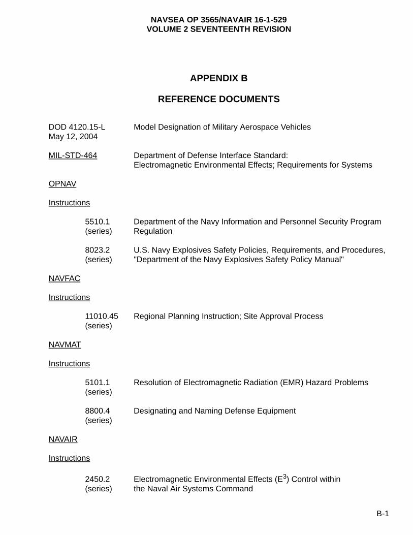
NAVSEA OP 3565/NAVAIR 16-1-529VOLUME 2 SEVENTEENTH REVISION
APPENDIX B
REFERENCE DOCUMENTS
DOD 4120.15-L Model Designation of Military Aerospace VehiclesMay 12, 2004
MIL-STD-464 Department of Defense Interface Standard: Electromagnetic Environmental Effects; Requirements for Systems
OPNAV
Instructions
5510.1 Department of the Navy Information and Personnel Security Program(series) Regulation
8023.2 U.S. Navy Explosives Safety Policies, Requirements, and Procedures, (series) "Department of the Navy Explosives Safety Policy Manual"
NAVFAC
Instructions
11010.45 Regional Planning Instruction; Site Approval Process(series)
NAVMAT
Instructions
5101.1 Resolution of Electromagnetic Radiation (EMR) Hazard Problems(series)
8800.4 Designating and Naming Defense Equipment(series)
NAVAIR
Instructions
2450.2 Electromagnetic Environmental Effects (E3) Control within(series) the Naval Air Systems Command
B-1
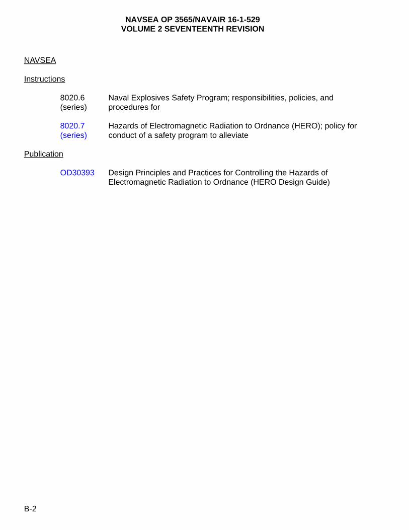
NAVSEA OP 3565/NAVAIR 16-1-529VOLUME 2 SEVENTEENTH REVISION
NAVSEA
Instructions
8020.6 Naval Explosives Safety Program; responsibilities, policies, and (series) procedures for
8020.7 Hazards of Electromagnetic Radiation to Ordnance (HERO); policy for (series) conduct of a safety program to alleviate
Publication
OD30393 Design Principles and Practices for Controlling the Hazards of Electromagnetic Radiation to Ordnance (HERO Design Guide)
B-2

NAVSEA OP 3565/NAVAIR 16-1-529VOLUME 2 SEVENTEENTH REVISION
APPENDIX C
HERO EMISSION CONTROL BILL WORKSHEETS
C-1. SAMPLE WORKSHEETS.
Sample copies of the worksheets required to develop a HERO EMCON bill, as described in chapter 5, are provided in this appendix. Included are: Figure C-1, “Sample Emitter Worksheet”, Figure C-2, “Sample Ordnance Location Worksheet”, and Figure C-3, “Sample Emitter Safe Separation Distances versus Distance to Ordnance Locations”. Figures C-1 through C-3 may be reproduced for use when developing a HERO EMCON bill.
C-1
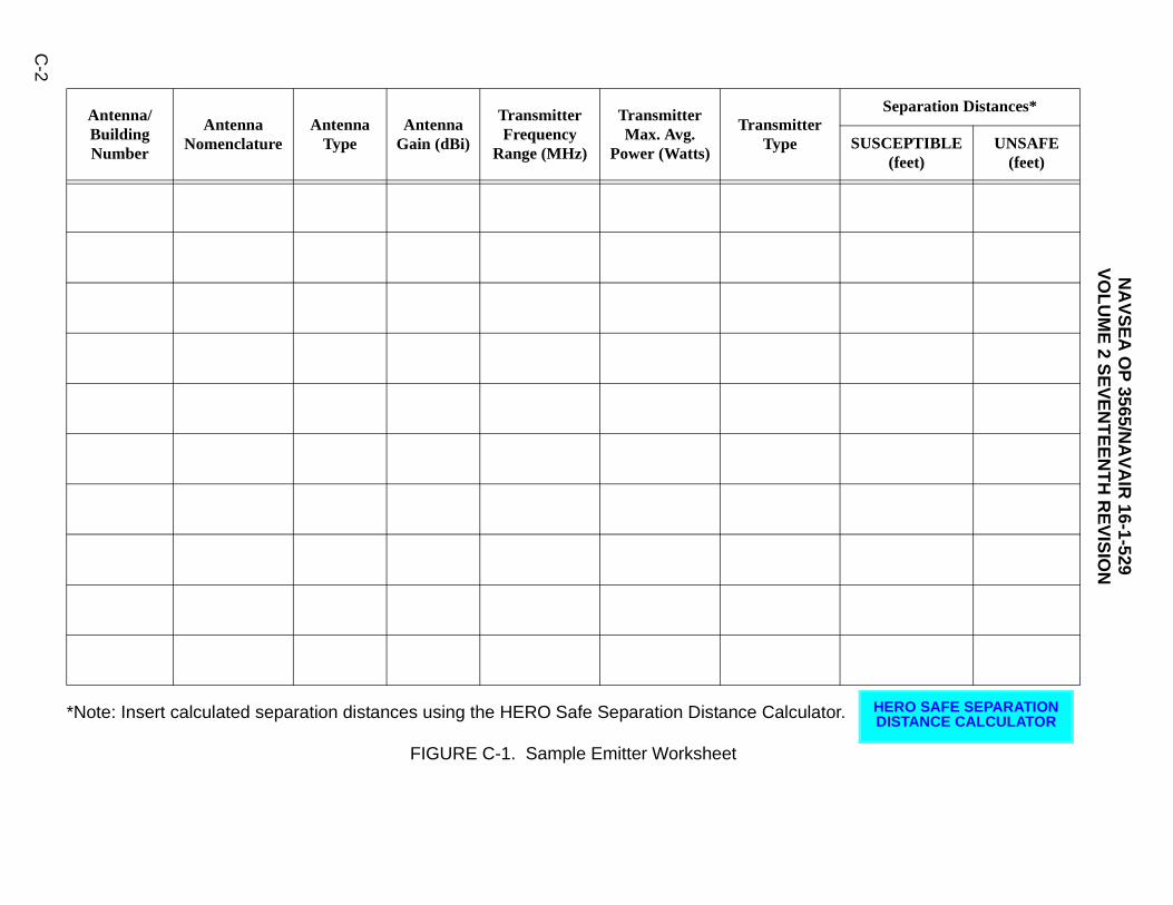
NA
VS
EA
OP
3565/NA
VA
IR 16-1-529
VO
LU
ME
2 SE
VE
NT
EE
NT
H R
EV
ISIO
N
C-2
tor.
rSeparation Distances*
SUSCEPTIBLE(feet)
UNSAFE(feet)
HERO SAFE SEPARATION DISTANCE CALCULATOR
*Note: Insert calculated separation distances using the HERO Safe Separation Distance CalculaFIGURE C-1. Sample Emitter Worksheet
Antenna/BuildingNumber
Antenna Nomenclature
AntennaType
AntennaGain (dBi)
Transmitter Frequency
Range (MHz)
Transmitter Max. Avg.
Power (Watts)
TransmitteType
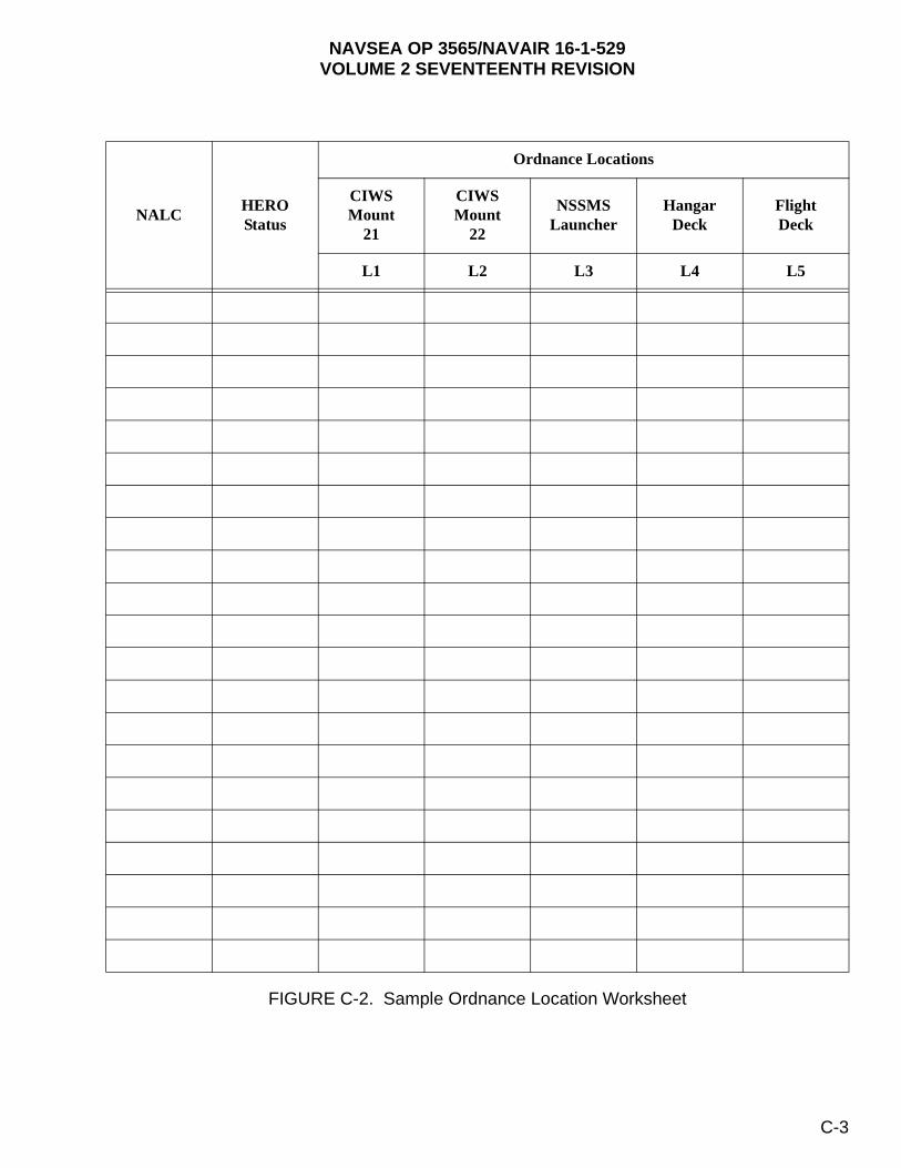
NAVSEA OP 3565/NAVAIR 16-1-529VOLUME 2 SEVENTEENTH REVISION
FIGURE C-2. Sample Ordnance Location Worksheet
NALCHEROStatus
Ordnance Locations
CIWSMount
21
CIWSMount
22
NSSMSLauncher
HangarDeck
FlightDeck
L1 L2 L3 L4 L5
C-3
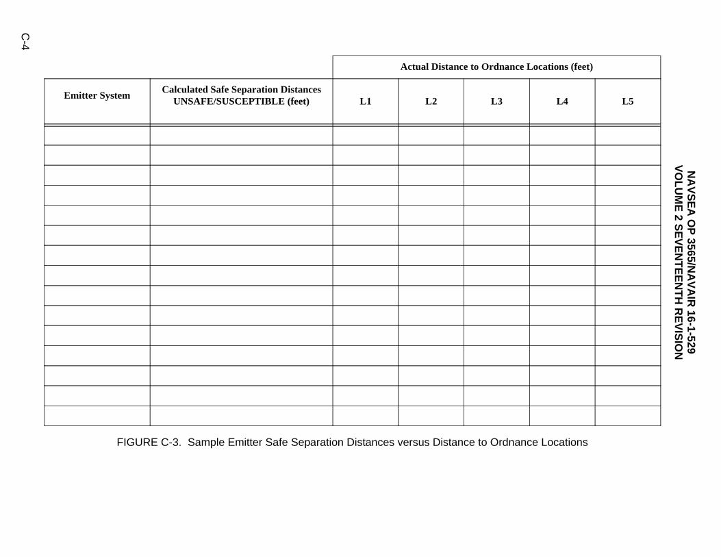
NA
VS
EA
OP
3565/NA
VA
IR 16-1-529
VO
LU
ME
2 SE
VE
NT
EE
NT
H R
EV
ISIO
N
C-4
dnance Locations
ance Locations (feet)
L4 L5
FIGURE C-3. Sample Emitter Safe Separation Distances versus Distance to Or
Actual Distance to Ordn
Emitter SystemCalculated Safe Separation Distances
UNSAFE/SUSCEPTIBLE (feet) L1 L2 L3
NAVSEA OP 3565/NAVAIR 16-1-529VOLUME 2 SEVENTEENTH REVISION
APPENDIX D
SAMPLE HAZARDS OF ELECTROMAGNETIC RADIATION TO ORDNANCE INSTRUCTIONS FOR SHIPS AND SHORE ACTIVITIES
D-1. INTRODUCTION.
As they are developed, HERO EMCON bills shall be incorporated into a HERO instruction specifically written for each ship and shore activity. To assist in this process, this appendix contains two sample HERO instructions, one for ships and one for shore activities.
D-2. SAMPLE HERO INSTRUCTIONS.
Figure D-1 is an example of an instruction written to address HERO policy and procedures for safe handling, transportation, and stowage of ordnance aboard a Naval ship. Figure D-2 is an example of an instruction written to address HERO policy and procedures for safe handling, transportation, and storage of ordnance at a Naval station or facility.
D-1

NAVSEA OP 3565/NAVAIR 16-1-529VOLUME 2 SEVENTEENTH REVISION
FIGURE D-1. Sample Hazards of Electromagnetic Radiation to Ordnance Instruction for Ships (Sheet 1 of 12)
SHIP NAME HERO INSTRUCTION 8020.xx
Subj: HAZARDS OF ELECTROMAGNETIC RADIATION TO ORDNANCE (HERO)
Ref: (a) Hazards of Electromagnetic Radiation to Ordnance Assessment of Ship Name(Hull #) , Mon 03
(b) Electromagnetic Radiation Hazards (Hazards to Ordnance), NAVSEA OP 3565/ NAVAIR 16-1-529, Volume 2 (latest issue)
Encl: (1) General HERO Requirements (2) Ordnance (3) Ship Drawings (4) HERO Summary (5) HERO EMCON Procedures (6) Antenna and Transmitter Systems (7) HERO Warning Label
1. Purpose. To promulgate policy and procedures for safe handling, transportation, and stowage of ordnance with regard to HERO. Enclosure (1) lists the general HERO requirements. The information contained in enclosures (2) through (7) is provided in reference (a), the current HERO assessment report for this ship.
2. Cancellation. This is a complete instruction and cancels all previous instructions.
3. Scope. This instruction is applicable anytime ordnance operations are conducted onboard this ship.
4. General Discussion. As described in reference (b), electromagnetic radiation (EMR) hazards stem from the functional characteristics of electrically initiated ordnance, and are a result of absorption of electromagnetic energy by the firing circuitry of electrically initiated devices (EIDs). The induced energy can cause heating of the bridgewire and primary explosive, and can result in premature, unintended actuation of the EID. Such an event can pose either a safety or reliability problem. In general, ordnance is most susceptible to radio frequency (RF) electromagnetic environments (EME’s) during assembly, disassembly, handling, loading, and unloading. There are three classifications pertinent to HERO: HERO SAFE ORDNANCE, HERO SUSCEPTIBLE ORDNANCE, and HERO UNSAFE ORDNANCE. Therefore, HERO emission control (EMCON) and ordnance handling restrictions and procedures [see reference (a)] form a compromise which allows for the safe handling of ordnance within the existing EME. EMCON is derived from an analysis of the EMEs produced by the existing antenna/transmitter systems and the ordnance susceptibilities described in reference (b), or through a HERO survey. The following paragraphs describe the categories of ordnance.
a. HERO SAFE ORDNANCE: Items that require no EME restrictions beyond the general HERO requirements described in paragraph 7-3 of reference (b).
Sample
D-2
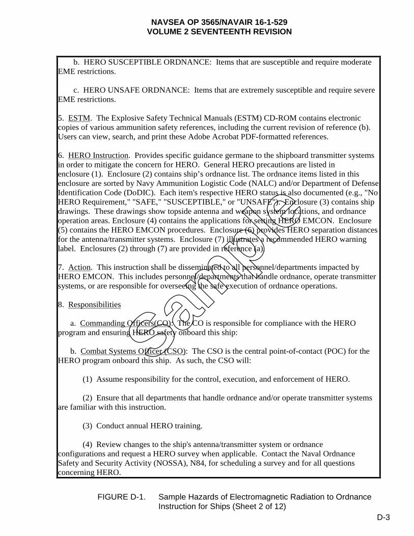
NAVSEA OP 3565/NAVAIR 16-1-529VOLUME 2 SEVENTEENTH REVISION
FIGURE D-1. Sample Hazards of Electromagnetic Radiation to Ordnance Instruction for Ships (Sheet 2 of 12)
SAMPLE ONLY
2
b. HERO SUSCEPTIBLE ORDNANCE: Items that are susceptible and require moderate EME restrictions.
c. HERO UNSAFE ORDNANCE: Items that are extremely susceptible and require severe EME restrictions.
5. ESTM. The Explosive Safety Technical Manuals (ESTM) CD-ROM contains electronic copies of various ammunition safety references, including the current revision of reference (b). Users can view, search, and print these Adobe Acrobat PDF-formatted references.
6. HERO Instruction. Provides specific guidance germane to the shipboard transmitter systems in order to mitigate the concern for HERO. General HERO precautions are listed in enclosure (1). Enclosure (2) contains ship’s ordnance list. The ordnance items listed in this enclosure are sorted by Navy Ammunition Logistic Code (NALC) and/or Department of Defense Identification Code (DoDIC). Each item's respective HERO status is also documented (e.g., "No HERO Requirement," "SAFE," "SUSCEPTIBLE," or "UNSAFE"). Enclosure (3) contains ship drawings. These drawings show topside antenna and weapon system locations, and ordnance operation areas. Enclosure (4) contains the applications for setting HERO EMCON. Enclosure (5) contains the HERO EMCON procedures. Enclosure (6) provides HERO separation distances for the antenna/transmitter systems. Enclosure (7) illustrates a recommended HERO warning label. Enclosures (2) through (7) are provided in reference (a).
7. Action. This instruction shall be disseminated to all personnel/departments impacted by HERO EMCON. This includes personnel/departments that handle ordnance, operate transmitter systems, or are responsible for overseeing the safe execution of ordnance operations.
8. Responsibilities
a. Commanding Officers(CO): The CO is responsible for compliance with the HERO program and ensuring HERO safety onboard this ship:
b. Combat Systems Officer (CSO): The CSO is the central point-of-contact (POC) for the HERO program onboard this ship. As such, the CSO will:
(1) Assume responsibility for the control, execution, and enforcement of HERO.
(2) Ensure that all departments that handle ordnance and/or operate transmitter systems are familiar with this instruction.
(3) Conduct annual HERO training.
(4) Review changes to the ship's antenna/transmitter system or ordnance configurations and request a HERO survey when applicable. Contact the Naval Ordnance Safety and Security Activity (NOSSA), N84, for scheduling a survey and for all questions concerning HERO.
Sample
D-3
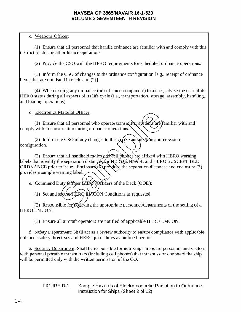
NAVSEA OP 3565/NAVAIR 16-1-529VOLUME 2 SEVENTEENTH REVISION
FIGURE D-1. Sample Hazards of Electromagnetic Radiation to Ordnance Instruction for Ships (Sheet 3 of 12)
SAMPLE ONLY c. Weapons Officer:
(1) Ensure that all personnel that handle ordnance are familiar with and comply with this instruction during all ordnance operations.
(2) Provide the CSO with the HERO requirements for scheduled ordnance operations.
(3) Inform the CSO of changes to the ordnance configuration [e.g., receipt of ordnance items that are not listed in enclosure (2)].
(4) When issuing any ordnance (or ordnance component) to a user, advise the user of its HERO status during all aspects of its life cycle (i.e., transportation, storage, assembly, handling, and loading operations).
d. Electronics Material Officer:
(1) Ensure that all personnel who operate transmitter systems are familiar with and comply with this instruction during ordnance operations.
(2) Inform the CSO of any changes to the ship’s antenna/transmitter system configuration.
(3) Ensure that all handheld radios and cell phones are affixed with HERO warning labels that identify the separation distances for HERO UNSAFE and HERO SUSCEPTIBLE ORDNANCE prior to issue. Enclosure (6) provides the separation distances and enclosure (7) provides a sample warning label.
e. Command Duty Officer (CDO)/Officers of the Deck (OOD):
(1) Set and secure HERO EMCON Conditions as requested.
(2) Responsible for notifying the appropriate personnel/departments of the setting of a HERO EMCON.
(3) Ensure all aircraft operators are notified of applicable HERO EMCON.
f. Safety Department: Shall act as a review authority to ensure compliance with applicable ordnance safety directives and HERO procedures as outlined herein.
g. Security Department: Shall be responsible for notifying shipboard personnel and visitors with personal portable transmitters (including cell phones) that transmissions onboard the ship will be permitted only with the written permission of the CO.
Sample
D-4

NAVSEA OP 3565/NAVAIR 16-1-529VOLUME 2 SEVENTEENTH REVISION
FIGURE D-1. Sample Hazards of Electromagnetic Radiation to Ordnance Instruction for Ships (Sheet 4 of 12)
SAMPLE ONLY 9. Requirements: To ensure ordnance safety, precautions must be taken to limit EME’s during ordnance operations. Enclosure (1) contains standard HERO precautions and chapter 7 of reference (b) provides HERO requirements during ordnance operations.
10. Procedures: Apply the following procedures whenever ordnance operations are conducted onboard this ship, ships in company, or ships moored adjacent to this ship.
a. Implement the following procedures to determine the appropriate HERO EMCON to set:
(1) Identify the HERO status of the ordnance item(s) involved in the operation [see enclosure (2)].
(2) For ordnance listed as UNSAFE or SUSCEPTIBLE:
(a) Identify the location where the ordnance operation will occur [see enclosure (3)].
(b) Select the proper HERO Condition associated with the location and HERO classification [see enclosure (4)].
(c) Apply the appropriate HERO EMCON Procedures [see enclosure (5)].
(3) For ordnance listed as SAFE, set HERO CONDITION 0 [see enclosure (5)].
(4) Items listed as “NO HERO REQ.” require no EMCON.
(5) For ordnance items not listed in enclosure (2), see reference (b).
b. Implement the following procedures to set HERO EMCON:
(1) Upon notification by the CSO, the CDO/OOD shall announce the appropriate HERO EMCON over the 1MC. Example: "Set HERO CONDITION 3 for CIWS Upload. Make reports to CDO/OOD." (Repeat).
(2) The CDO/OOD will then execute a HERO status board to ensure the appropriate transmitter/antenna systems are secured. Upon receiving all reports that the specified HERO condition has been set, the CDO/OOD will pass the word, "HERO CONDITION ____ Set, Time _______."
(3) The CDO/OOD will act as the HERO Control Center and shall maintain an up-to-date status board showing the current HERO Condition in effect.
(4) When notified by the CSO that HERO requirements have ended, the CDO/OOD will pass over the 1MC "Secure from HERO CONDITION ___." (Repeat)
Sample
D-5

NAVSEA OP 3565/NAVAIR 16-1-529VOLUME 2 SEVENTEENTH REVISION
FIGURE D-1. Sample Hazards of Electromagnetic Radiation to Ordnance Instruction for Ships (Sheet 5 of 12)
5
GENERAL HERO REQUIREMENTS
1. The following requirements apply to all ordnance operations involving the presence, handling, and loading/unloading of ordnance unless otherwise specified in NAVSEA OP 3565/ NAVAIR 16-1-529.
a. Ordnance evolutions must be planned so that there is a minimum of ordnance exposure to the EME’s.
b. Avoid touching any exposed firing contact, wiring, or other exposed circuitry with any part of the body or with any metallic object.
c. Ensure all open electrical connectors on the ordnance are covered with non-shorting caps.
d. Ordnance will not be assembled/disassembled in an EME.
e. Ignitors, primers, detonators, and other items containing EIDs will not be stowed in magazines that have flexible waveguides routed through them.
2. Store HERO UNSAFE ORDNANCE within authorized spaces onboard the ship.
3. For ordnance transfers in port, comply with local facility EMCON instruction and handling requirements listed in chapter 7 of reference (b).
4. When traveling in company, employ a common EMCON plan; i.e., apply the appropriate separation distance(s) listed in enclosure (6) for affected antenna(s) with respect to HERO-classified ordnance that could be present on deck.
5. During vertical replenishment operations, maintain a minimum separation distance of 50 feet between HERO SAFE ORDNANCE and any radiating antenna. For HERO SUSCEPTIBLE ORDNANCE, maintain the separation distances listed in enclosure (6) between the ordnance operation and affected antenna(s); otherwise, silence the applicable antenna(s).
6. During connected replenishment operations when physical contact between ships has been made using metal cables, silence transmitter systems operating in the 2-30 MHz frequency range on both ships when HERO SUSCEPTIBLE ORDNANCE is present on the weather decks of either ship. Silence fire-control radar systems that can directly illuminate these same operations on either ship. Apply the appropriate EMCON, if any, for air- and surface-search radars. Navigational radars aboard either ship need not be silenced.
7. Do not expose individual ordnance components to EME’s. Install components into ordnance systems in authorized ordnance spaces below decks. Upon completion of ordnance system assembly, individual components assume the HERO classification of the resultant all-up round.
Enclosure (1)
Sample
D-6

NAVSEA OP 3565/NAVAIR 16-1-529VOLUME 2 SEVENTEENTH REVISION
FIGURE D-1. Sample Hazards of Electromagnetic Radiation to Ordnance Instruction for Ships (Sheet 6 of 12)
6
8. For ordnance operations involving L-FORM and EOD items, transport in sealed, all-metal containers or MIL-PRF-81705 Type 1 standard barrier bags. Should exposure of HEROUNSAFE ORDNANCE occur on weather decks during transport, set HERO CONDITION 1 aslisted in enclosure (4).
9. Establish a HERO liaison to brief and monitor units (i.e., USMC expeditionary units) deployed onboard. The liaison should coordinate the HERO program and account for all unit command information concerning ordnance inventory/operations and transmitter/antenna systems present.
10. Maintain control over the number, type, and placement of temporary emitter systems installed onboard the ship. The safe separation distances should be reviewed prior to installation and compared to the on-board ordnance locations in order to minimize HERO.
11. Do not illuminate aircraft in flight (launch and recovery) or on deck with fire-control radars/directors. Apply the separation distances provided in enclosure (6).
12. Observe the HERO separation distances listed in enclosure (6) for cellular telephones and mobile and portable radios, and affix HERO warning labels stating separation distances for HERO UNSAFE and HERO SUSCEPTIBLE ORDNANCE to units.
13. For transmitters not specifically addressed in enclosure (6), see reference (b) for HERO guidance.
14. In cases where HERO UNSAFE or HERO SUSCEPTIBLE ORDNANCE items are encountered that are not addressed by this instruction, refer to the EMCON guidance provided in enclosure (4) and enclosure (5) to set the appropriate HERO Condition.
Enclosure (1)
Sample
D-7

NAVSEA OP 3565/NAVAIR 16-1-529VOLUME 2 SEVENTEENTH REVISION
FIGURE D-1. Sample Hazards of Electromagnetic Radiation to Ordnance Instruction for Ships (Sheet 7 of 12)
7
ORDNANCE LIST
Insert Appendix B of reference (a) here.
Enclosure (2)
Sample
D-8
NAVSEA OP 3565/NAVAIR 16-1-529VOLUME 2 SEVENTEENTH REVISION
FIGURE D-1. Sample Hazards of Electromagnetic Radiation to Ordnance Instruction for Ships (Sheet 8 of 12)
SAMPLE ONLY
8
SHIP DRAWINGS
Insert Appendix C of reference (a) here.
Enclosure (3)
Sample
D-9

NAVSEA OP 3565/NAVAIR 16-1-529VOLUME 2 SEVENTEENTH REVISION
FIGURE D-1. Sample Hazards of Electromagnetic Radiation to Ordnance Instruction for Ships (Sheet 9 of 12)
9
HERO SUMMARY
Insert Table 1 of reference (a) here.
Enclosure (4)
Sample
D-10

NAVSEA OP 3565/NAVAIR 16-1-529VOLUME 2 SEVENTEENTH REVISION
FIGURE D-1. Sample Hazards of Electromagnetic Radiation to Ordnance Instruction for Ships (Sheet 10 of 12)
10
HERO EMCON PROCEDURES
Insert Table 2 of reference (a) here.
Enclosure (5)
Sample
D-11
NAVSEA OP 3565/NAVAIR 16-1-529VOLUME 2 SEVENTEENTH REVISION
FIGURE D-1. Sample Hazards of Electromagnetic Radiation to Ordnance Instruction for Ships (Sheet 11 of 12)
11
ANTENNA AND TRANSMITTER SYSTEMS
Insert Appendix A of reference (a) here.
Enclosure (6)
Sample
D-12

NAVSEA OP 3565/NAVAIR 16-1-529VOLUME 2 SEVENTEENTH REVISION
FIGURE D-1. Sample Hazards of Electromagnetic Radiation to Ordnance Instruction for Ships (Sheet 12 of 12)
SAMPLE ONLY HERO WARNING LABEL
The HERO warning label shown below is to be affixed to mobile and portable communications radios. This warning label alerts a radio operator to a potential hazard if the radio is operated within the prescribed distance of ordnance operations.
HERO WARNING LABEL
The table below provides data pertaining to the above label. The label has blank spaces forinserting HERO SUSCEPTIBLE or HERO UNSAFE separation distances in feet. The distances are obtained from enclosure (6) of this instruction for individual radios. The smaller label is recommended for hand-held portable radios and the larger for mobiles.
HERO WARNING LABEL INFORMATION*NAVSEA FORM STOCK NUMBER SIZE DESCRIPTIONNAVSEA 5104/3 0116-LF-115-0700 2” x 22/3” RADHAZ Warning Label
(Blank) Feet NAVSEA 5104/4 0116-LF-115-0800 11/2” x 21/3” RADHAZ Warning Label
(Blank) Feet *Available from Document Automation & Production Service (DAPS) Philadelphia:1-877-327-7226 or on the WorldWide Web at http:/navalforms.daps.dla.mil/.
Enclosure (7)
Sample
D-13
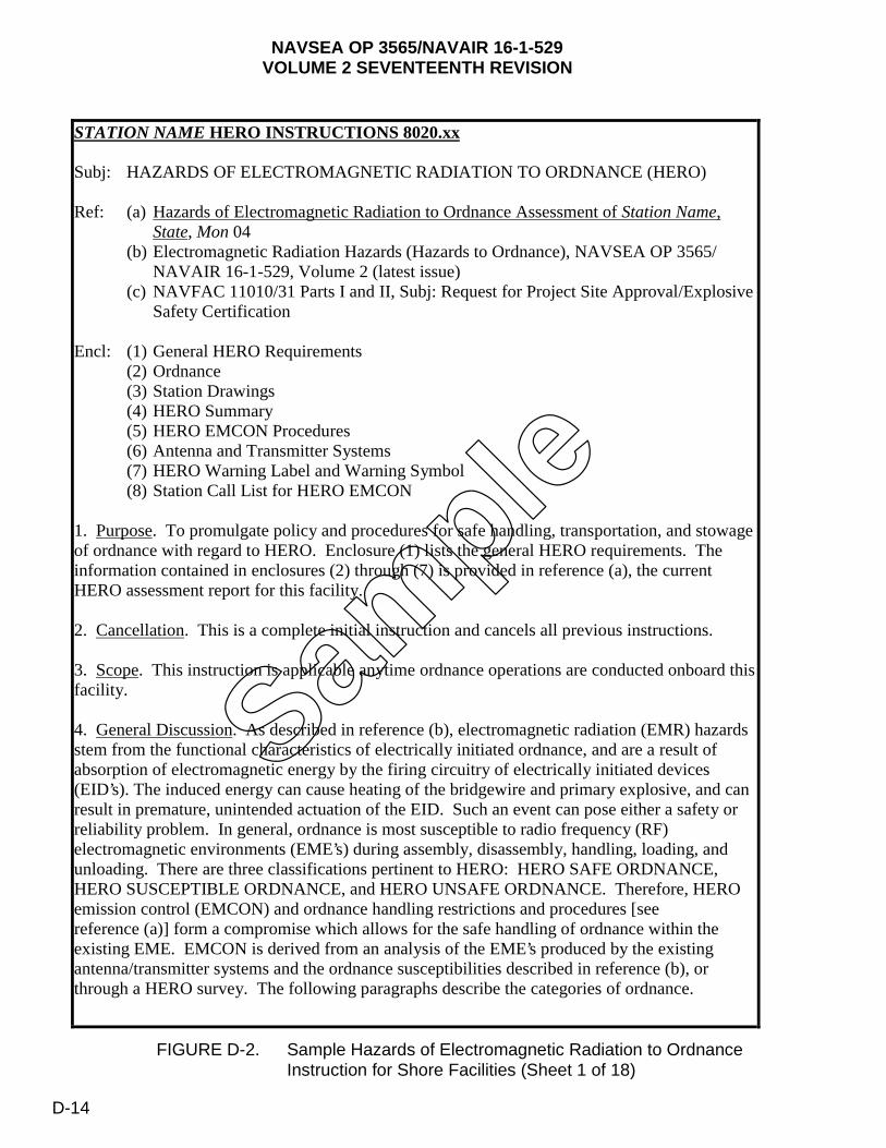
NAVSEA OP 3565/NAVAIR 16-1-529VOLUME 2 SEVENTEENTH REVISION
FIGURE D-2. Sample Hazards of Electromagnetic Radiation to Ordnance Instruction for Shore Facilities (Sheet 1 of 18)
1
STATION NAME HERO INSTRUCTIONS 8020.xx
Subj: HAZARDS OF ELECTROMAGNETIC RADIATION TO ORDNANCE (HERO)
Ref: (a) Hazards of Electromagnetic Radiation to Ordnance Assessment of Station Name,State, Mon 04
(b) Electromagnetic Radiation Hazards (Hazards to Ordnance), NAVSEA OP 3565/ NAVAIR 16-1-529, Volume 2 (latest issue)
(c) NAVFAC 11010/31 Parts I and II, Subj: Request for Project Site Approval/Explosive Safety Certification
Encl: (1) General HERO Requirements (2) Ordnance (3) Station Drawings (4) HERO Summary (5) HERO EMCON Procedures (6) Antenna and Transmitter Systems (7) HERO Warning Label and Warning Symbol (8) Station Call List for HERO EMCON
1. Purpose. To promulgate policy and procedures for safe handling, transportation, and stowage of ordnance with regard to HERO. Enclosure (1) lists the general HERO requirements. The information contained in enclosures (2) through (7) is provided in reference (a), the current HERO assessment report for this facility.
2. Cancellation. This is a complete initial instruction and cancels all previous instructions.
3. Scope. This instruction is applicable anytime ordnance operations are conducted onboard this facility.
4. General Discussion. As described in reference (b), electromagnetic radiation (EMR) hazards stem from the functional characteristics of electrically initiated ordnance, and are a result of absorption of electromagnetic energy by the firing circuitry of electrically initiated devices (EID’s). The induced energy can cause heating of the bridgewire and primary explosive, and can result in premature, unintended actuation of the EID. Such an event can pose either a safety or reliability problem. In general, ordnance is most susceptible to radio frequency (RF) electromagnetic environments (EME’s) during assembly, disassembly, handling, loading, and unloading. There are three classifications pertinent to HERO: HERO SAFE ORDNANCE, HERO SUSCEPTIBLE ORDNANCE, and HERO UNSAFE ORDNANCE. Therefore, HERO emission control (EMCON) and ordnance handling restrictions and procedures [see reference (a)] form a compromise which allows for the safe handling of ordnance within the existing EME. EMCON is derived from an analysis of the EME’s produced by the existing antenna/transmitter systems and the ordnance susceptibilities described in reference (b), or through a HERO survey. The following paragraphs describe the categories of ordnance.
Sample
D-14
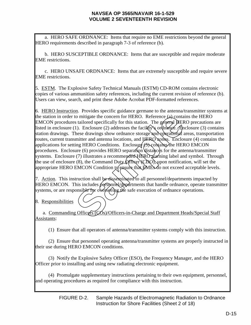
NAVSEA OP 3565/NAVAIR 16-1-529VOLUME 2 SEVENTEENTH REVISION
FIGURE D-2. Sample Hazards of Electromagnetic Radiation to Ordnance Instruction for Shore Facilities (Sheet 2 of 18)
2
a. HERO SAFE ORDNANCE: Items that require no EME restrictions beyond the general HERO requirements described in paragraph 7-3 of reference (b).
b. HERO SUSCEPTIBLE ORDNANCE: Items that are susceptible and require moderate EME restrictions.
c. HERO UNSAFE ORDNANCE: Items that are extremely susceptible and require severe EME restrictions.
5. ESTM. The Explosive Safety Technical Manuals (ESTM) CD-ROM contains electronic copies of various ammunition safety references, including the current revision of reference (b). Users can view, search, and print these Adobe Acrobat PDF-formatted references.
6. HERO Instruction. Provides specific guidance germane to the antenna/transmitter systems at the station in order to mitigate the concern for HERO. Reference (a) contains the HERO EMCON procedures tailored specifically for this station. The general HERO precautions are listed in enclosure (1). Enclosure (2) addresses the facility’s ordnance. Enclosure (3) contains station drawings. These drawings show ordnance storage and operational areas, transportation routes, current transmitter and antenna locations, and HERO zones. Enclosure (4) contains the applications for setting HERO Conditions. Enclosure (5) contains the HERO EMCON procedures. Enclosure (6) provides HERO separation distances for the antenna/transmitter systems. Enclosure (7) illustrates a recommended HERO warning label and symbol. Through the use of enclosure (8), the Command Duty Officer (CDO), upon notification, will set the appropriate HERO EMCON Condition to ensure that EMEs do not exceed acceptable levels.
7. Action. This instruction shall be disseminated to all personnel/departments impacted by HERO EMCON. This includes personnel/departments that handle ordnance, operate transmitter systems, or are responsible for overseeing the safe execution of ordnance operations.
8. Responsibilities
a. Commanding Officers (COs)/Officers-in-Charge and Department Heads/Special Staff Assistants:
(1) Ensure that all operators of antenna/transmitter systems comply with this instruction.
(2) Ensure that personnel operating antenna/transmitter systems are properly instructed in their use during HERO EMCON conditions.
(3) Notify the Explosive Safety Officer (ESO), the Frequency Manager, and the HERO Officer prior to installing and using new radiating electronic equipment.
(4) Promulgate supplementary instructions pertaining to their own equipment, personnel, and operating procedures as required for compliance with this instruction.
Sample
D-15
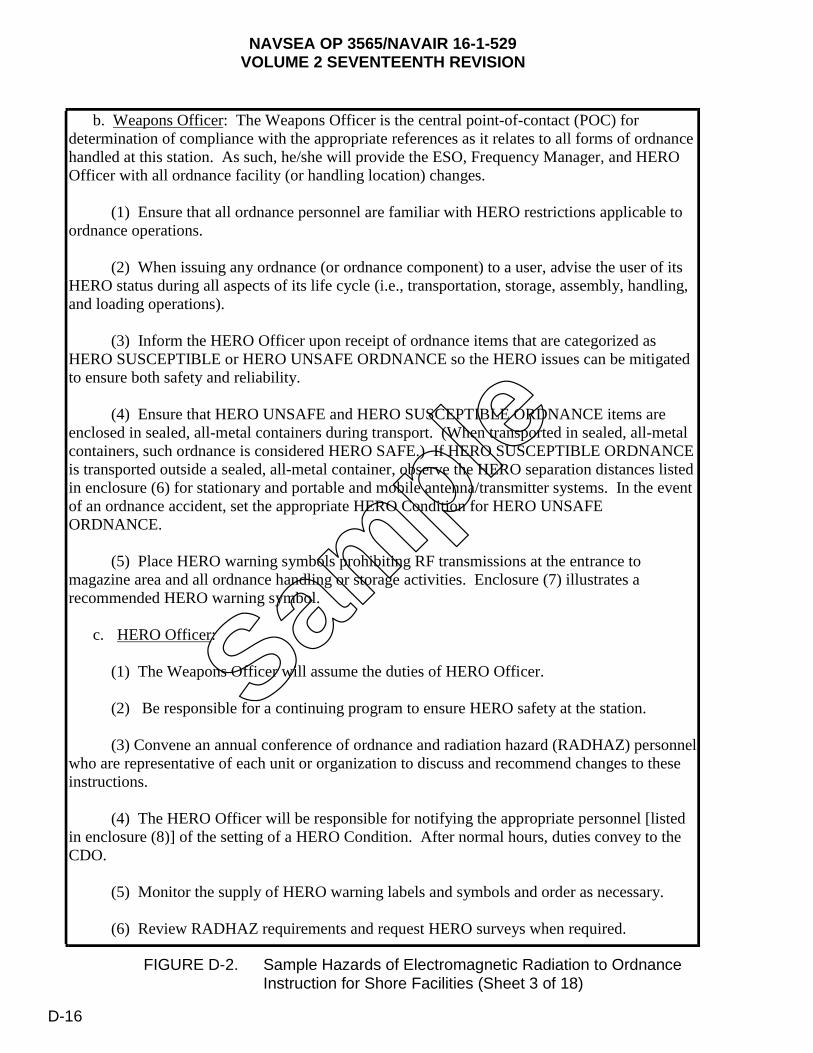
NAVSEA OP 3565/NAVAIR 16-1-529VOLUME 2 SEVENTEENTH REVISION
FIGURE D-2. Sample Hazards of Electromagnetic Radiation to Ordnance Instruction for Shore Facilities (Sheet 3 of 18)
3
b. Weapons Officer: The Weapons Officer is the central point-of-contact (POC) for determination of compliance with the appropriate references as it relates to all forms of ordnance handled at this station. As such, he/she will provide the ESO, Frequency Manager, and HERO Officer with all ordnance facility (or handling location) changes.
(1) Ensure that all ordnance personnel are familiar with HERO restrictions applicable to ordnance operations.
(2) When issuing any ordnance (or ordnance component) to a user, advise the user of its HERO status during all aspects of its life cycle (i.e., transportation, storage, assembly, handling, and loading operations).
(3) Inform the HERO Officer upon receipt of ordnance items that are categorized as HERO SUSCEPTIBLE or HERO UNSAFE ORDNANCE so the HERO issues can be mitigated to ensure both safety and reliability.
(4) Ensure that HERO UNSAFE and HERO SUSCEPTIBLE ORDNANCE items are enclosed in sealed, all-metal containers during transport. (When transported in sealed, all-metal containers, such ordnance is considered HERO SAFE.) If HERO SUSCEPTIBLE ORDNANCE is transported outside a sealed, all-metal container, observe the HERO separation distances listed in enclosure (6) for stationary and portable and mobile antenna/transmitter systems. In the event of an ordnance accident, set the appropriate HERO Condition for HERO UNSAFE ORDNANCE.
(5) Place HERO warning symbols prohibiting RF transmissions at the entrance to magazine area and all ordnance handling or storage activities. Enclosure (7) illustrates a recommended HERO warning symbol.
c. HERO Officer:
(1) The Weapons Officer will assume the duties of HERO Officer.
(2) Be responsible for a continuing program to ensure HERO safety at the station.
(3) Convene an annual conference of ordnance and radiation hazard (RADHAZ) personnel who are representative of each unit or organization to discuss and recommend changes to these instructions.
(4) The HERO Officer will be responsible for notifying the appropriate personnel [listed in enclosure (8)] of the setting of a HERO Condition. After normal hours, duties convey to the CDO.
(5) Monitor the supply of HERO warning labels and symbols and order as necessary.
(6) Review RADHAZ requirements and request HERO surveys when required.
Sample
D-16

NAVSEA OP 3565/NAVAIR 16-1-529VOLUME 2 SEVENTEENTH REVISION
FIGURE D-2. Sample Hazards of Electromagnetic Radiation to Ordnance Instruction for Shore Facilities (Sheet 4 of 18)
4
d. Explosive Safety Officer: The ESO is the central POC for determination of compliance with the appropriate references as it relates to all forms of ordnance safety at this station. As such, he/she will assist the Weapons Officer in tracking and monitoring all future ordnance facility (or handling location) changes.
(1) Act as a HERO liaison with the HERO Officer and Frequency Manager to track and monitor all future antenna/transmitter system and ordnance changes.
(2) Coordinate the HERO program.
(3) Account for all command and tenant information as presented in enclosures (2) and (6) concerning ordnance operations and antenna/transmitter systems present.
(4) Assist the HERO Officer and Frequency Manager in ensuring future antenna/transmitter system changes at the station are submitted for HERO review. This includes, but is not limited to, the following: Approve/disapprove (on recommendations from the Frequency Manager) all new or modified antenna/transmitter system installations and frequency coordination at this station. Contact the Naval Ordnance Safety and Security Activity (NOSSA), N84, for all questions concerning HERO.
e. Frequency Manager:
(1) The Frequency Manager shall be responsible for the analysis of planned alternations to the existing antenna/transmitter system configurations and shall advise the CO on the HERO EMCON impact before executing the plan.
(2) Ensure that all mobile and portable radios under the cognizance of this command are affixed with HERO warning labels to identify safe separation distances prior to issue.
(3) Inform the Weapons Officer, ESO, HERO Officer, and the Safety Department when stationary transmitters/antenna systems are relocated or new equipment is obtained. These changes should be submitted for HERO review in accordance with reference (c).
(4) Establish check-in procedures for owners of citizens band and other mobile radios and cellular telephones to familiarize operators with HERO.
(5) Approve/disapprove any request to operate amateur radio equipment at the station.
f. Operations Officer:
(1) When requested, set and secure HERO EMCON Conditions as requested.
(2) Ensure all aircraft are notified of applicable HERO Conditions.
Sample
D-17

NAVSEA OP 3565/NAVAIR 16-1-529VOLUME 2 SEVENTEENTH REVISION
FIGURE D-2. Sample Hazards of Electromagnetic Radiation to Ordnance Instruction for Shore Facilities (Sheet 5 of 18)
5
(3) Maintain liaison with tenant commands to resolve any conflicts in setting HERO EMCON Conditions.
(4) Designate a member of the Operations Department as the Command RADHAZ Control Officer.
g. Safety Department: Shall act as a review authority to ensure compliance with applicable ordnance safety directives and HERO procedures as outlined herein.
h. Security Department: Shall be responsible for notifying station personnel and visitors who have mobile transmitters in their personal vehicles that transmission onboard the station will be permitted only with the written permission of the CO.
i. Fire Department: In the event of an ordnance accident or incident, shall act as on-scene commander until such time as the situation has been resolved [i.e., Explosive Ordnance Disposal (EOD) responds and the item is rendered safe, or the item is determined safe to transport].
j. Tenant commands and activities:
(1) Shall be responsible for notifying the ESO and HERO Officer of any operation involving HERO SUSCEPTIBLE ORDNANCE or HERO UNSAFE ORDNANCE that would require the setting of a HERO Condition.
(2) Shall be responsible for ensuring HERO UNSAFE ORDNANCE is completely enclosed in sealed, all-metal containers during storage and during transfer between designated safe areas.
9. Requirements: To ensure ordnance safety, precautions must be taken to limit EME’s in and around ordnance handling areas. Enclosure (1) contains standard HERO precautions and Chapter 5 of reference (b) provides HERO requirements during ordnance operations.
a. When ordnance is being assembled, handled, or transported within the confines of the station, emissions from various mobile and portable antenna/transmitter systems should be silenced or the HERO UNSAFE and HERO SUSCEPTIBLE ORDNANCE safe separation distances provided in enclosure (6) or chapter 2 of reference (b) should be maintained.
b. HERO UNSAFE or HERO SUSCEPTIBLE ORDNANCE cannot be moved, transported, or loaded except as specified by the Weapons Officer, ESO, and the HERO Officer. Enclosures (4) and (5) provide specific HERO EMCON guidance.
c. Other conditions necessitating deviations from the requirements outlined in reference (b) shall be reported to NOSSA, N84, in accordance with reference (b).
d. The CDO will be responsible for notifying the appropriate personnel [listed in enclosure (8)] of the setting of a HERO Condition after normal working hours. In addition, the
Sample
D-18

NAVSEA OP 3565/NAVAIR 16-1-529VOLUME 2 SEVENTEENTH REVISION
FIGURE D-2. Sample Hazards of Electromagnetic Radiation to Ordnance Instruction for Shore Facilities (Sheet 6 of 18)
6
CDO will receive reports that the ordered HERO Condition is set and report to the HERO Officer.
e. Officers and supervisors shall be responsible for notifying each operator of a government vehicle containing a mobile transmitter that the transmitter is not to be energized within the safe separation distances provided in enclosure (6).
f. Each civilian employee or military person having a radio transmitter installed in his/her personal vehicle is responsible for its registration with the Safety Department, in accordance with reference (b). (Note: Registration does not authorize use.) One copy of the registration form shall be kept in the vehicle with the radio at all times while at the station; the second copy will remain on file at the Pass and Identification Office. Privately owned radios shall not be operated in any restricted area or in other parts of the station while in sight of a vehicle (train or truck) that exhibits an explosive placard.
g. Each mobile and portable transmitter shall be conspicuously marked (at the operator’s location) with the appropriate distance taken from enclosure (6) and marked by a (RADHAZ) cautionary decal. Cautionary decals will be provided by the HERO Officer/Frequency Manager.
h. Commands, contractors, and their representatives will coordinate frequency assignment matters through the appropriate Department of the Navy Area Frequency Coordinator and station Frequency Manager.
10. Procedures
a. Implement the following procedures to determine the appropriate HERO EMCON to set:
(1) Identify the HERO status of ordnance item(s) involved in the operation [see enclosure (2)].
(2) For ordnance item(s) listed as HERO UNSAFE or HERO SUSCEPTIBLE:
(a) Identify the HERO zone where the ordnance operation will occur [see enclosure (3)].
(b) Select the proper HERO Condition associated with the HERO zone and HERO classification [see enclosure (4)].
(c) Apply the appropriate HERO EMCON procedures [see enclosure (5)].
(3) For ordnance items(s) listed as HERO SAFE, set HERO CONDITION 0 [see enclosure (4)].
(4) Item(s) listed as “No HERO Req.” require no HERO EMCON.
Sample
D-19
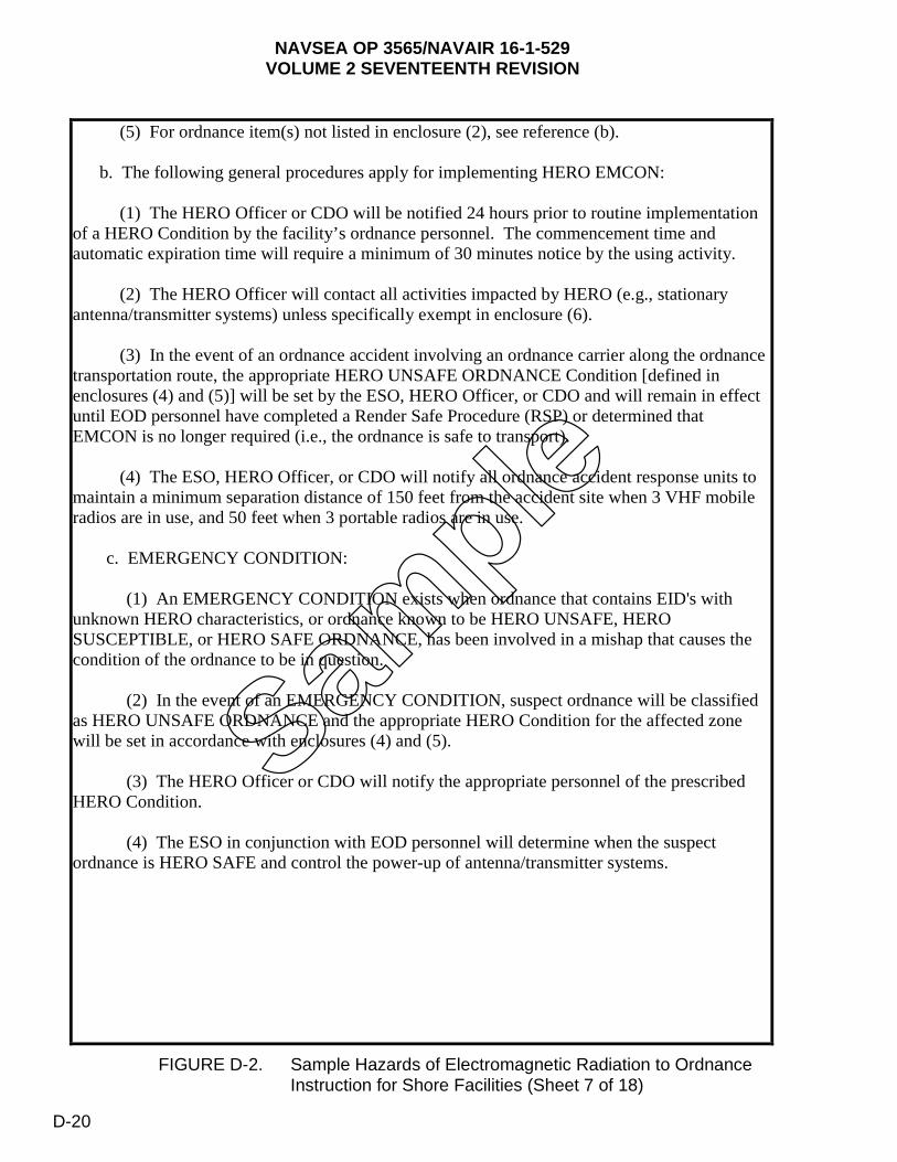
NAVSEA OP 3565/NAVAIR 16-1-529VOLUME 2 SEVENTEENTH REVISION
FIGURE D-2. Sample Hazards of Electromagnetic Radiation to Ordnance Instruction for Shore Facilities (Sheet 7 of 18)
7
(5) For ordnance item(s) not listed in enclosure (2), see reference (b).
b. The following general procedures apply for implementing HERO EMCON:
(1) The HERO Officer or CDO will be notified 24 hours prior to routine implementation of a HERO Condition by the facility’s ordnance personnel. The commencement time and automatic expiration time will require a minimum of 30 minutes notice by the using activity.
(2) The HERO Officer will contact all activities impacted by HERO (e.g., stationary antenna/transmitter systems) unless specifically exempt in enclosure (6).
(3) In the event of an ordnance accident involving an ordnance carrier along the ordnance transportation route, the appropriate HERO UNSAFE ORDNANCE Condition [defined in enclosures (4) and (5)] will be set by the ESO, HERO Officer, or CDO and will remain in effect until EOD personnel have completed a Render Safe Procedure (RSP) or determined that EMCON is no longer required (i.e., the ordnance is safe to transport).
(4) The ESO, HERO Officer, or CDO will notify all ordnance accident response units to maintain a minimum separation distance of 150 feet from the accident site when 3 VHF mobile radios are in use, and 50 feet when 3 portable radios are in use.
c. EMERGENCY CONDITION:
(1) An EMERGENCY CONDITION exists when ordnance that contains EID's with unknown HERO characteristics, or ordnance known to be HERO UNSAFE, HERO SUSCEPTIBLE, or HERO SAFE ORDNANCE, has been involved in a mishap that causes the condition of the ordnance to be in question.
(2) In the event of an EMERGENCY CONDITION, suspect ordnance will be classified as HERO UNSAFE ORDNANCE and the appropriate HERO Condition for the affected zone will be set in accordance with enclosures (4) and (5).
(3) The HERO Officer or CDO will notify the appropriate personnel of the prescribed HERO Condition.
(4) The ESO in conjunction with EOD personnel will determine when the suspect ordnance is HERO SAFE and control the power-up of antenna/transmitter systems.
Sample
D-20
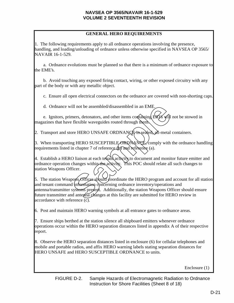
NAVSEA OP 3565/NAVAIR 16-1-529VOLUME 2 SEVENTEENTH REVISION
FIGURE D-2. Sample Hazards of Electromagnetic Radiation to Ordnance Instruction for Shore Facilities (Sheet 8 of 18)
GENERAL HERO REQUIREMENTS
1. The following requirements apply to all ordnance operations involving the presence, handling, and loading/unloading of ordnance unless otherwise specified in NAVSEA OP 3565/ NAVAIR 16-1-529.
a. Ordnance evolutions must be planned so that there is a minimum of ordnance exposure to the EME’s.
b. Avoid touching any exposed firing contact, wiring, or other exposed circuitry with any part of the body or with any metallic object.
c. Ensure all open electrical connectors on the ordnance are covered with non-shorting caps.
d. Ordnance will not be assembled/disassembled in an EME.
e. Ignitors, primers, detonators, and other items containing EID’s will not be stowed in magazines that have flexible waveguides routed through them.
2. Transport and store HERO UNSAFE ORDNANCE in sealed, all-metal containers.
3. When transporting HERO SUSCEPTIBLE ORDNANCE, comply with the ordnance handling requirements listed in chapter 7 of reference (b) and reference (a).
4. Establish a HERO liaison at each tenant activity to document and monitor future emitter and ordnance operation changes within the activity. This POC should relate all such changes to station Weapons Officer.
5. The station Weapons Officer should coordinate the HERO program and account for all station and tenant command information concerning ordnance inventory/operations and antenna/transmitter systems present. Additionally, the station Weapons Officer should ensure future transmitter and antenna changes at this facility are submitted for HERO review in accordance with reference (c).
6. Post and maintain HERO warning symbols at all entrance gates to ordnance areas.
7. Ensure ships berthed at the station silence all shipboard emitters whenever ordnance operations occur within the HERO separation distances listed in appendix A of their respective report.
8. Observe the HERO separation distances listed in enclosure (6) for cellular telephones and mobile and portable radios, and affix HERO warning labels stating separation distances for HERO UNSAFE and HERO SUSCEPTIBLE ORDNANCE to units.
Enclosure (1)
Sample
D-21
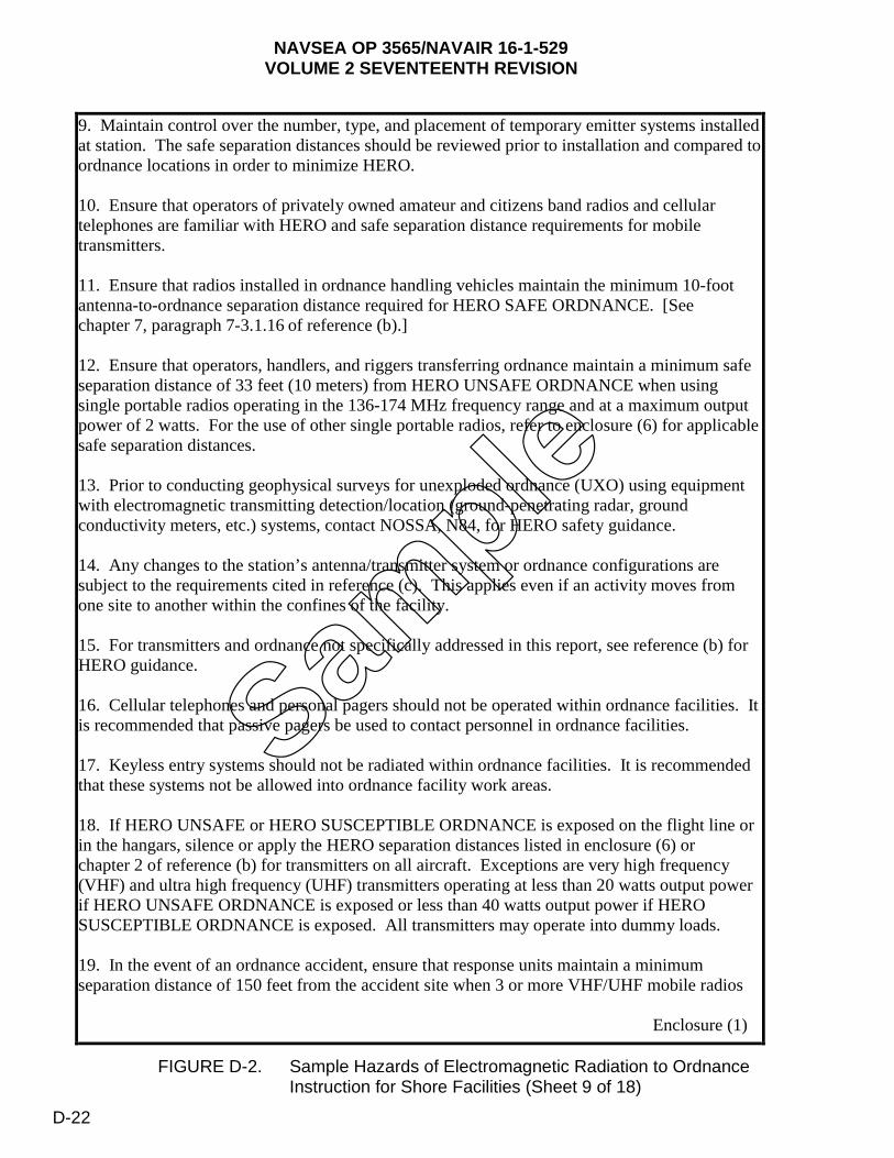
NAVSEA OP 3565/NAVAIR 16-1-529VOLUME 2 SEVENTEENTH REVISION
FIGURE D-2. Sample Hazards of Electromagnetic Radiation to Ordnance Instruction for Shore Facilities (Sheet 9 of 18)
9. Maintain control over the number, type, and placement of temporary emitter systems installed at station. The safe separation distances should be reviewed prior to installation and compared to ordnance locations in order to minimize HERO.
10. Ensure that operators of privately owned amateur and citizens band radios and cellular telephones are familiar with HERO and safe separation distance requirements for mobile transmitters.
11. Ensure that radios installed in ordnance handling vehicles maintain the minimum 10-foot antenna-to-ordnance separation distance required for HERO SAFE ORDNANCE. [See chapter 7, paragraph 7-3.1.16 of reference (b).]
12. Ensure that operators, handlers, and riggers transferring ordnance maintain a minimum safe separation distance of 33 feet (10 meters) from HERO UNSAFE ORDNANCE when using single portable radios operating in the 136-174 MHz frequency range and at a maximum output power of 2 watts. For the use of other single portable radios, refer to enclosure (6) for applicable safe separation distances.
13. Prior to conducting geophysical surveys for unexploded ordnance (UXO) using equipment with electromagnetic transmitting detection/location (ground-penetrating radar, ground conductivity meters, etc.) systems, contact NOSSA, N84, for HERO safety guidance.
14. Any changes to the station’s antenna/transmitter system or ordnance configurations are subject to the requirements cited in reference (c). This applies even if an activity moves from one site to another within the confines of the facility.
15. For transmitters and ordnance not specifically addressed in this report, see reference (b) for HERO guidance.
16. Cellular telephones and personal pagers should not be operated within ordnance facilities. It is recommended that passive pagers be used to contact personnel in ordnance facilities.
17. Keyless entry systems should not be radiated within ordnance facilities. It is recommended that these systems not be allowed into ordnance facility work areas.
18. If HERO UNSAFE or HERO SUSCEPTIBLE ORDNANCE is exposed on the flight line or in the hangars, silence or apply the HERO separation distances listed in enclosure (6) or chapter 2 of reference (b) for transmitters on all aircraft. Exceptions are very high frequency (VHF) and ultra high frequency (UHF) transmitters operating at less than 20 watts output power if HERO UNSAFE ORDNANCE is exposed or less than 40 watts output power if HERO SUSCEPTIBLE ORDNANCE is exposed. All transmitters may operate into dummy loads.
19. In the event of an ordnance accident, ensure that response units maintain a minimum separation distance of 150 feet from the accident site when 3 or more VHF/UHF mobile radios
Enclosure (1)
Sample
D-22

NAVSEA OP 3565/NAVAIR 16-1-529VOLUME 2 SEVENTEENTH REVISION
FIGURE D-2. Sample Hazards of Electromagnetic Radiation to Ordnance Instruction for Shore Facilities (Sheet 10 of 18)
are in use, and 50 feet when 3 or more portable VHF radios are in use. For single VHF radio use, see the applicable separation distances listed in enclosure (6).
Enclosure (1)
Sample
D-23
NAVSEA OP 3565/NAVAIR 16-1-529VOLUME 2 SEVENTEENTH REVISION
FIGURE D-2. Sample Hazards of Electromagnetic Radiation to Ordnance Instruction for Shore Facilities (Sheet 11 of 18)
11
ORDNANCE
Insert Appendix B of reference (a) here.
Enclosure (2)
Sample
D-24
NAVSEA OP 3565/NAVAIR 16-1-529VOLUME 2 SEVENTEENTH REVISION
FIGURE D-2. Sample Hazards of Electromagnetic Radiation to Ordnance Instruction for Shore Facilities (Sheet 12 of 18)
12
STATION DRAWINGS
Insert Appendix C of reference (a) here.
Enclosure (3)
Sample
D-25
NAVSEA OP 3565/NAVAIR 16-1-529VOLUME 2 SEVENTEENTH REVISION
FIGURE D-2. Sample Hazards of Electromagnetic Radiation to Ordnance Instruction for Shore Facilities (Sheet 13 of 18)
13
HERO SUMMARY
Insert Table 1 of reference (a) here.
Enclosure (4)
Sample
D-26

NAVSEA OP 3565/NAVAIR 16-1-529VOLUME 2 SEVENTEENTH REVISION
FIGURE D-2. Sample Hazards of Electromagnetic Radiation to Ordnance Instruction for Shore Facilities (Sheet 14 of 18)
14
HERO EMCON PROCEDURES
Insert Table 2 of reference (a) here.
Enclosure (5)
Sample
D-27

NAVSEA OP 3565/NAVAIR 16-1-529VOLUME 2 SEVENTEENTH REVISION
FIGURE D-2. Sample Hazards of Electromagnetic Radiation to Ordnance Instruction for Shore Facilities (Sheet 15 of 18)
15
ANTENNA AND TRANSMITTER SYSTEMS
Insert Appendix A of reference (a) here.
Enclosure (6)
Sample
D-28
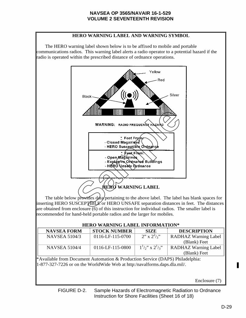
NAVSEA OP 3565/NAVAIR 16-1-529VOLUME 2 SEVENTEENTH REVISION
FIGURE D-2. Sample Hazards of Electromagnetic Radiation to Ordnance Instruction for Shore Facilities (Sheet 16 of 18)
HERO WARNING LABEL AND WARNING SYMBOL
The HERO warning label shown below is to be affixed to mobile and portable communications radios. This warning label alerts a radio operator to a potential hazard if the radio is operated within the prescribed distance of ordnance operations.
HERO WARNING LABEL
The table below provides data pertaining to the above label. The label has blank spaces for inserting HERO SUSCEPTIBLE or HERO UNSAFE separation distances in feet. The distances are obtained from enclosure (6) of this instruction for individual radios. The smaller label is recommended for hand-held portable radios and the larger for mobiles.
HERO WARNING LABEL INFORMATION* NAVSEA FORM STOCK NUMBER SIZE DESCRIPTION NAVSEA 5104/3 0116-LF-115-0700 2” x 22/3” RADHAZ Warning Label
(Blank) Feet NAVSEA 5104/4 0116-LF-115-0800 11/2” x 21/3” RADHAZ Warning Label
(Blank) Feet *Available from Document Automation & Production Service (DAPS) Philadelphia:1-877-327-7226 or on the WorldWide Web at http:/navalforms.daps.dla.mil/.
Enclosure (7)
Sample
D-29
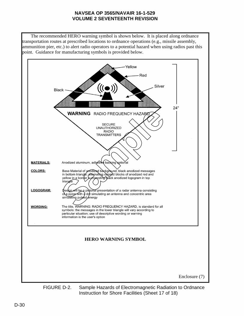
NAVSEA OP 3565/NAVAIR 16-1-529VOLUME 2 SEVENTEENTH REVISION
FIGURE D-2. Sample Hazards of Electromagnetic Radiation to Ordnance Instruction for Shore Facilities (Sheet 17 of 18)
The recommended HERO warning symbol is shown below. It is placed along ordnance transportation routes at prescribed locations to ordnance operations (e.g., missile assembly, ammunition pier, etc.) to alert radio operators to a potential hazard when using radios past this point. Guidance for manufacturing symbols is provided below.
HERO WARNING SYMBOL
Enclosure (7)
Sample
D-30
NAVSEA OP 3565/NAVAIR 16-1-529VOLUME 2 SEVENTEENTH REVISION
FIGURE D-2. Sample Hazards of Electromagnetic Radiation to Ordnance Instruction for Shore Facilities (Sheet 18 of 18)
18
STATION CALL LIST FOR HERO EMCON
The Explosive Safety Officer/HERO Officer should generate and maintain a list of names and phone numbers for those activities impacted by HERO EMCON and provide to the Command Duty Officer/Officer of the Day.
Enclosure (8)
Sample
D-31/(D-32 Blank)

This page left intentionally blank
NAVSEA OP 3565/NAVAIR 16-1-529VOLUME 2 SEVENTEENTH REVISION
APPENDIX E
HERO SURVEY PERIODICITY CHART
E-1. HERO SURVEY PERIODICITY REQUIREMENTS.
HERO surveys must be conducted at designated intervals, as described in paragraph 6-1.4. The 5-, 7-, and 10- year cycles are established based upon the activity’s number of transmitters, intensity of ordnance operations, and rate of change to system or operations.
E-2. PERIODICITY CHART.
Table E-1, ‘HERO Survey for Shore Facilities” is a list of activities showing the periodicity and the date for the next scheduled survey. The activity’s designated periodicity may change as a result of factors listed in paragraph E-1, changes to the above. Periodicity changes will be reflected in regularly scheduled updates to table E-1.
E-3.
The periodicity schedule shown in table E-1 is based on emitters and ordnance as found at the time of the last HERO survey. If any changes occur in emitter power output, frequency of the emitters, or there are any changes in the type of ordnance handled, a survey or engineering analysis may be required earlier than the scheduled periodicity date.
E-1
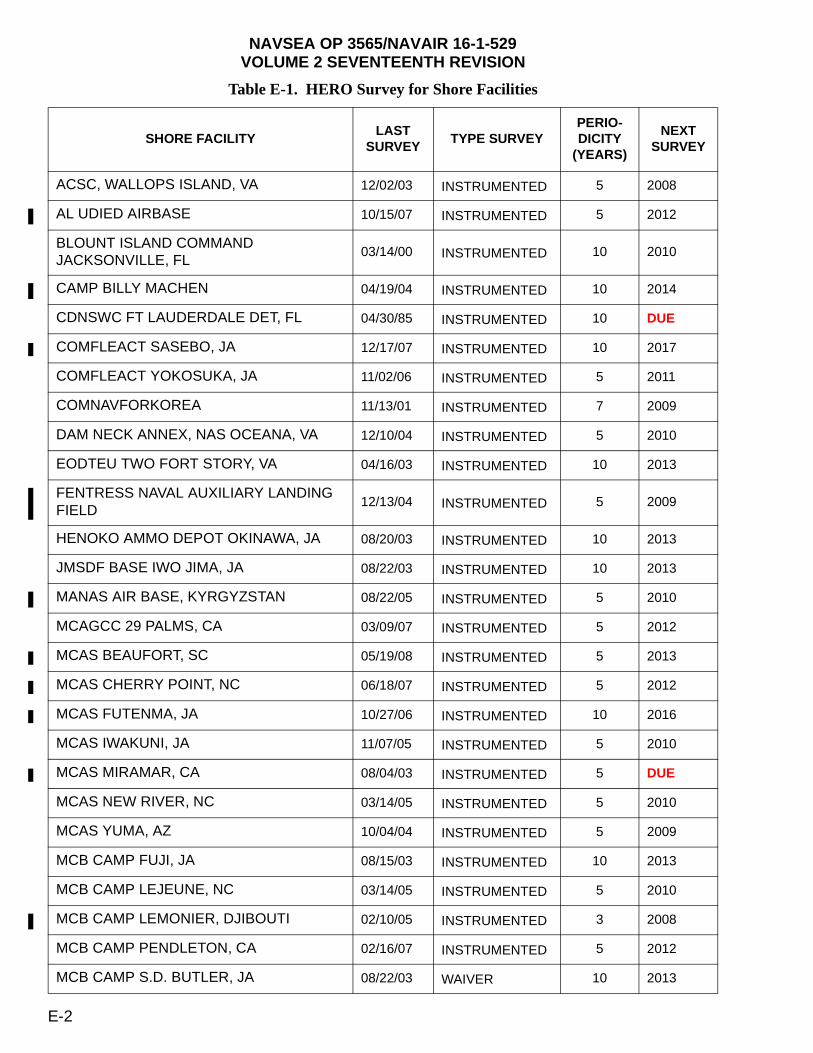
NAVSEA OP 3565/NAVAIR 16-1-529VOLUME 2 SEVENTEENTH REVISION
Table E-1. HERO Survey for Shore Facilities
SHORE FACILITYLAST
SURVEYTYPE SURVEY
PERIO-DICITY
(YEARS)
NEXT SURVEY
ACSC, WALLOPS ISLAND, VA 12/02/03 INSTRUMENTED 5 2008
AL UDIED AIRBASE 10/15/07 INSTRUMENTED 5 2012
BLOUNT ISLAND COMMAND JACKSONVILLE, FL
03/14/00 INSTRUMENTED 10 2010
CAMP BILLY MACHEN 04/19/04 INSTRUMENTED 10 2014
CDNSWC FT LAUDERDALE DET, FL 04/30/85 INSTRUMENTED 10 DUE
COMFLEACT SASEBO, JA 12/17/07 INSTRUMENTED 10 2017
COMFLEACT YOKOSUKA, JA 11/02/06 INSTRUMENTED 5 2011
COMNAVFORKOREA 11/13/01 INSTRUMENTED 7 2009
DAM NECK ANNEX, NAS OCEANA, VA 12/10/04 INSTRUMENTED 5 2010
EODTEU TWO FORT STORY, VA 04/16/03 INSTRUMENTED 10 2013
FENTRESS NAVAL AUXILIARY LANDING FIELD
12/13/04 INSTRUMENTED 5 2009
HENOKO AMMO DEPOT OKINAWA, JA 08/20/03 INSTRUMENTED 10 2013
JMSDF BASE IWO JIMA, JA 08/22/03 INSTRUMENTED 10 2013
MANAS AIR BASE, KYRGYZSTAN 08/22/05 INSTRUMENTED 5 2010
MCAGCC 29 PALMS, CA 03/09/07 INSTRUMENTED 5 2012
MCAS BEAUFORT, SC 05/19/08 INSTRUMENTED 5 2013
MCAS CHERRY POINT, NC 06/18/07 INSTRUMENTED 5 2012
MCAS FUTENMA, JA 10/27/06 INSTRUMENTED 10 2016
MCAS IWAKUNI, JA 11/07/05 INSTRUMENTED 5 2010
MCAS MIRAMAR, CA 08/04/03 INSTRUMENTED 5 DUE
MCAS NEW RIVER, NC 03/14/05 INSTRUMENTED 5 2010
MCAS YUMA, AZ 10/04/04 INSTRUMENTED 5 2009
MCB CAMP FUJI, JA 08/15/03 INSTRUMENTED 10 2013
MCB CAMP LEJEUNE, NC 03/14/05 INSTRUMENTED 5 2010
MCB CAMP LEMONIER, DJIBOUTI 02/10/05 INSTRUMENTED 3 2008
MCB CAMP PENDLETON, CA 02/16/07 INSTRUMENTED 5 2012
MCB CAMP S.D. BUTLER, JA 08/22/03 WAIVER 10 2013
E-2
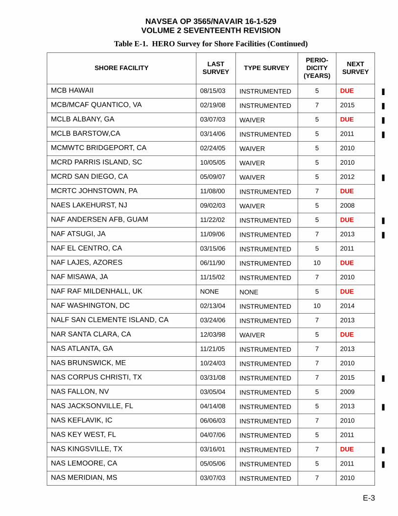
NAVSEA OP 3565/NAVAIR 16-1-529VOLUME 2 SEVENTEENTH REVISION
MCB HAWAII 08/15/03 INSTRUMENTED 5 DUE
MCB/MCAF QUANTICO, VA 02/19/08 INSTRUMENTED 7 2015
MCLB ALBANY, GA 03/07/03 WAIVER 5 DUE
MCLB BARSTOW,CA 03/14/06 INSTRUMENTED 5 2011
MCMWTC BRIDGEPORT, CA 02/24/05 WAIVER 5 2010
MCRD PARRIS ISLAND, SC 10/05/05 WAIVER 5 2010
MCRD SAN DIEGO, CA 05/09/07 WAIVER 5 2012
MCRTC JOHNSTOWN, PA 11/08/00 INSTRUMENTED 7 DUE
NAES LAKEHURST, NJ 09/02/03 WAIVER 5 2008
NAF ANDERSEN AFB, GUAM 11/22/02 INSTRUMENTED 5 DUE
NAF ATSUGI, JA 11/09/06 INSTRUMENTED 7 2013
NAF EL CENTRO, CA 03/15/06 INSTRUMENTED 5 2011
NAF LAJES, AZORES 06/11/90 INSTRUMENTED 10 DUE
NAF MISAWA, JA 11/15/02 INSTRUMENTED 7 2010
NAF RAF MILDENHALL, UK NONE NONE 5 DUE
NAF WASHINGTON, DC 02/13/04 INSTRUMENTED 10 2014
NALF SAN CLEMENTE ISLAND, CA 03/24/06 INSTRUMENTED 7 2013
NAR SANTA CLARA, CA 12/03/98 WAIVER 5 DUE
NAS ATLANTA, GA 11/21/05 INSTRUMENTED 7 2013
NAS BRUNSWICK, ME 10/24/03 INSTRUMENTED 7 2010
NAS CORPUS CHRISTI, TX 03/31/08 INSTRUMENTED 7 2015
NAS FALLON, NV 03/05/04 INSTRUMENTED 5 2009
NAS JACKSONVILLE, FL 04/14/08 INSTRUMENTED 5 2013
NAS KEFLAVIK, IC 06/06/03 INSTRUMENTED 7 2010
NAS KEY WEST, FL 04/07/06 INSTRUMENTED 5 2011
NAS KINGSVILLE, TX 03/16/01 INSTRUMENTED 7 DUE
NAS LEMOORE, CA 05/05/06 INSTRUMENTED 5 2011
NAS MERIDIAN, MS 03/07/03 INSTRUMENTED 7 2010
Table E-1. HERO Survey for Shore Facilities (Continued)
SHORE FACILITYLAST
SURVEYTYPE SURVEY
PERIO-DICITY
(YEARS)
NEXT SURVEY
E-3
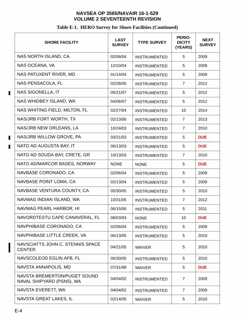
NAVSEA OP 3565/NAVAIR 16-1-529VOLUME 2 SEVENTEENTH REVISION
NAS NORTH ISLAND, CA 02/06/04 INSTRUMENTED 5 2009
NAS OCEANA, VA 12/10/04 INSTRUMENTED 5 2009
NAS PATUXENT RIVER, MD 01/14/04 INSTRUMENTED 5 2009
NAS PENSACOLA, FL 02/28/05 INSTRUMENTED 7 2012
NAS SIGONELLA, IT 05/21/07 INSTRUMENTED 5 2012
NAS WHIDBEY ISLAND, WA 04/06/07 INSTRUMENTED 5 2012
NAS WHITING FIELD, MILTON, FL 02/27/04 INSTRUMENTED 10 2014
NAS/JRB FORT WORTH, TX 02/13/06 INSTRUMENTED 7 2013
NAS/JRB NEW ORLEANS, LA 10/24/03 INSTRUMENTED 7 2010
NAS/JRB WILLOW GROVE, PA 03/21/03 INSTRUMENTED 5 DUE
NATO AD AUGUSTA BAY, IT 06/13/03 INSTRUMENTED 5 DUE
NATO AD SOUDA BAY, CRETE, GR 10/13/03 INSTRUMENTED 7 2010
NATO AD/MARCOR BASES, NORWAY NONE NONE 5 DUE
NAVBASE CORONADO, CA 02/06/04 INSTRUMENTED 5 2009
NAVBASE POINT LOMA, CA 02/13/04 INSTRUMENTED 5 2009
NAVBASE VENTURA COUNTY, CA 05/30/05 INSTRUMENTED 5 2010
NAVMAG INDIAN ISLAND, WA 10/31/05 INSTRUMENTED 7 2012
NAVMAG PEARL HARBOR, HI 06/15/06 INSTRUMENTED 5 2011
NAVORDTESTU CAPE CANAVERAL, FL 08/03/93 NONE 10 DUE
NAVPHIBASE CORONADO, CA 02/06/04 INSTRUMENTED 5 2009
NAVPHIBASE LITTLE CREEK, VA 06/13/05 INSTRUMENTED 5 2010
NAVSCIATTS JOHN C. STENNIS SPACE CENTER
04/21/05 WAIVER 5 2010
NAVSCOLEOD EGLIN AFB, FL 05/30/05 INSTRUMENTED 5 2010
NAVSTA ANNAPOLIS, MD 07/31/98 WAIVER 5 DUE
NAVSTA BREMERTON/PUGET SOUND NAVAL SHIPYARD (PSNS), WA
04/04/02 INSTRUMENTED 7 2009
NAVSTA EVERETT, WA 04/04/02 INSTRUMENTED 7 2009
NAVSTA GREAT LAKES, IL 02/14/05 WAIVER 5 2010
Table E-1. HERO Survey for Shore Facilities (Continued)
SHORE FACILITYLAST
SURVEYTYPE SURVEY
PERIO-DICITY
(YEARS)
NEXT SURVEY
E-4

NAVSEA OP 3565/NAVAIR 16-1-529VOLUME 2 SEVENTEENTH REVISION
NAVSTA GUANTANAMO BAY, CUBA 11/07/03 INSTRUMENTED 7 2010
NAVSTA INGLESIDE, TX 01/29/02 INSTRUMENTED 7 2009
NAVSTA MAYPORT, FL 04/21/08 INSTRUMENTED 5 2013
NAVSTA NEWPORT, RI 02/20/06 WAIVER 5 2011
NAVSTA NORFOLK, VA 09/16/05 INSTRUMENTED 5 2010
NAVSTA PASCAGOULA, MS 08/02/04 INSTRUMENTED 7 2011
NAVSTA PEARL HARBOR, HI 06/15/06 INSTRUMENTED 5 2011
NAVSTA ROTA, SP 09/19/03 INSTRUMENTED 5 2008
NAVSTA SAN DIEGO, CA 02/19/04 INSTRUMENTED 5 2009
NAVY AUXILIARY LANDING FIELD, FENTRESS, VA
12/08/04 WAIVER 5 2010
NAVY DARE COUNTY RANGE, NC 12/10/04 WAIVER 5 2010
NAWCWD/NAS POINT MUGU, CA 05/30/05 INSTRUMENTED 5 2010
NAWS CHINA LAKE, CA 03/15/06 INSTRUMENTED 5 2011
NCBC GULFPORT, MS 10/01/96 WAIVER 5 DUE
NCBC PORT HUENEME, CA 05/30/05 INSTRUMENTED 5 2010
NDW ANNEX ANACOSTIA, WASHINGTON, DC
08/03/08 WAIVER 5 2013
NFA KADENA, OKINAWA, JA 11/10/06 INSTRUMENTED 5 2011
NNSY PORTSMOUTH, VA 04/24/02 INSTRUMENTED 10 2012
NOLF SAN NICHOLAS ISLAND 05/30/05 INSTRUMENTED 5 2010
NRL CHESAPEAKE BAY DET, MD 07/11/03 INSTRUMENTED 5 DUE
NRL WASHINGTON, DC 08/11/08 INSTRUMENTED 5 2013
NSA BAHRAIN 10/08/07 INSTRUMENTED 7 2014
NSA DAHLGREN, VA 10/13/04 INSTRUMENTED 7 2011
NSA GAETA, IT 06/18/03 INSTRUMENTED 10 2013
NSA MID SOUTH, TN 10/02/03 INSTRUMENTED 10 2013
NSA NAPLES, IT 05/29/07 INSTRUMENTED 10 2017
NSA NEW ORLEANS, LA 06/19/97 INSTRUMENTED 10 DUE
Table E-1. HERO Survey for Shore Facilities (Continued)
SHORE FACILITYLAST
SURVEYTYPE SURVEY
PERIO-DICITY
(YEARS)
NEXT SURVEY
E-5

NAVSEA OP 3565/NAVAIR 16-1-529VOLUME 2 SEVENTEENTH REVISION
NSA NORTHWEST ANNEX, VA 01/18/05 WAIVER 5 2010
NSA PANAMA CITY, FL 08/01/05 INSTRUMENTED 7 2012
NSA SOUDA BAY, GR 10/17/03 INSTRUMENTED 7 2011
NSF DIEGO GARCIA, BRITISH INDIAN OCEAN TERRITORY (BIOT)
08/25/06 INSTRUMENTED 5 2011
NSGA SUGAR GROVE, WV 03/13/03 WAIVER 5 DUE
NSWC CARDEROCK DIV, WEST BETHESDA, MD
02/09/00 INSTRUMENTED 10 2010
NSWC INDIAN HEAD DET MCALESTER, OK
NONE NONE 10 DUE
NSWC INDIAN HEAD, MD 04/25/05 INSTRUMENTED 5 2010
NSWC SMCA DET DOVER, NJ NONE NONE 5 DUE
NSWCDD CRANE, IN 05/17/04 INSTRUMENTED 7 2011
NSWCSS DET FORT MONROE, VA 06/21/96 WAIVER 1 DUE
NSY PORTSMOUTH, NH 01/15/07 WAIVER 5 2012
NUWC DET, AUTEC, ANDROS ISLAND, BAHAMAS
05/07/07 INSTRUMENTED 5 2012
NUWC DET, HAWTHORNE, NV 07/18/02 INSTRUMENTED 10 2012
NUWC DET, WAIANAE, HI 06/15/06 INSTRUMENTED 5 2011
NUWC DIVISION NEWPORT, RI 11/07/05 INSTRUMENTED 5 2010
NUWDC KEYPORT, WA 07/17/02 INSTRUMENTED 7 2009
NWF DET MACHRIHANISH, UK 10/05/87 INSTRUMENTED 5 DUE
NWF ST MAWGAN, UK 10/15/87 INSTRUMENTED 5 DUE
NWS CHARLESTON, SC 04/18/05 INSTRUMENTED 5 2010
NWS EARLE, COLTS NECK, NJ 10/12/06 INSTRUMENTED 7 2013
NWS SEAL BEACH det CONCORD, CA 03/17/03 WAIVER INDEF INDEF
NWS SEAL BEACH det FALLBROOK, CA 03/14/03 INSTRUMENTED 7 2010
NWS SEAL BEACH det POMONA, CA 03/14/03 INSTRUMENTED 7 2010
NWS SEAL BEACH, CA 03/14/03 INSTRUMENTED 7 2010
NWS YORKTOWN, VA 05/09/05 INSTRUMENTED 5 2010
Table E-1. HERO Survey for Shore Facilities (Continued)
SHORE FACILITYLAST
SURVEYTYPE SURVEY
PERIO-DICITY
(YEARS)
NEXT SURVEY
E-6
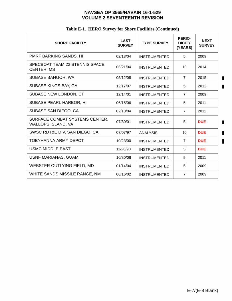
NAVSEA OP 3565/NAVAIR 16-1-529VOLUME 2 SEVENTEENTH REVISION
PMRF BARKING SANDS, HI 02/13/04 INSTRUMENTED 5 2009
SPECBOAT TEAM 22 STENNIS SPACE CENTER, MS
06/21/04 INSTRUMENTED 10 2014
SUBASE BANGOR, WA 05/12/08 INSTRUMENTED 7 2015
SUBASE KINGS BAY, GA 12/17/07 INSTRUMENTED 5 2012
SUBASE NEW LONDON, CT 12/14/01 INSTRUMENTED 7 2009
SUBASE PEARL HARBOR, HI 06/15/06 INSTRUMENTED 5 2011
SUBASE SAN DIEGO, CA 02/13/04 INSTRUMENTED 7 2011
SURFACE COMBAT SYSTEMS CENTER, WALLOPS ISLAND, VA
07/30/01 INSTRUMENTED 5 DUE
SWSC RDT&E DIV. SAN DIEGO, CA 07/07/97 ANALYSIS 10 DUE
TOBYHANNA ARMY DEPOT 10/23/00 INSTRUMENTED 7 DUE
USMC MIDDLE EAST 11/26/90 INSTRUMENTED 5 DUE
USNF MARIANAS, GUAM 10/30/06 INSTRUMENTED 5 2011
WEBSTER OUTLYING FIELD, MD 01/14/04 INSTRUMENTED 5 2009
WHITE SANDS MISSILE RANGE, NM 08/16/02 INSTRUMENTED 7 2009
Table E-1. HERO Survey for Shore Facilities (Continued)
SHORE FACILITYLAST
SURVEYTYPE SURVEY
PERIO-DICITY
(YEARS)
NEXT SURVEY
E-7/(E-8 Blank)

This page left intentionally blank

NAVSEA OP 3565/NAVAIR 16-1-529VOLUME 2 SEVENTEENTH REVISION
APPENDIX F
THE AIT HERO CERTIFICATION PROCESS
F-1. CERTIFICATION PROCESS
The following paragraphs describe the process for Hazards of Electromagnetic Radiation to Ordnance (HERO) certification of new or modified Automatic Identification Technology (AIT) equipments (see figure F-1). Furthermore, it outlines the steps necessary for an AIT manufacturer to have a HERO evaluation conducted (see figure F-2).
a. The Program Manager (PM), Acquisition Manager (AM), or Installation Activity (IA) responsible for the AIT equipment shall request a certification from the Naval Ordnance Safety and Security Activity (NOSSA) (N84), the HERO PM, and provide the necessary technical data (i.e., operational frequency, Effective Isotropic Radiated Power (EIRP)) to the Naval Surface Warfare Center, Dahlgren Division (NSWCDD). The information package will include a description of the intended system operation, such as network structure of AIT equipment and location (i.e., ordnance areas or magazines) and a description of the RF properties and any independent test data that the manufacturer has obtained as a result of radio-frequency (RF) testing.
b. NSWCDD shall review the request and AIT equipment documentation, and determine the evaluation method (analysis and/or measurement). NSWCDD shall develop a cost estimate to perform the evaluation and provide it, plus any request for additional information to support the evaluation, to the requesting manager or activity.
c. The PM, AM, or IA shall provide the necessary funding and any additional information to NSWCDD to perform the evaluation.
d. If a HERO measurement is required, NSWCDD shall prepare a test plan for the equipment to be evaluated, and provide a copy to the manager or activity.
e. NSWCDD shall schedule the HERO measurement based on the availability of the facilities and assets.
f. The AIT equipment PM shall provide all hardware to be evaluated to NSWCDD at least 10 days prior to the commencement of the measurements.
g. Upon completion of the evaluation, NSWCDD shall prepare a report detailing the results and conclusions of their assessment (to include the HERO UNSAFE or HERO UNRELIABLE, HERO SUSCEPTIBLE, and HERO SAFE ORDNANCE safe separation distances for the AIT equipment) and provide a copy to NOSSA (N84) and the PM, AM, or IA.
h. The NOSSA HERO PM shall review the assessment report and Certification Request along with supporting data and either approve or reject the request as follows:
F-1
NAVSEA OP 3565/NAVAIR 16-1-529VOLUME 2 SEVENTEENTH REVISION
(1) If the system has no HERO impact, and requires no safe separation distances for HERO UNSAFE or HERO UNRELIABLE, HERO SUSCEPTIBLE or HERO SAFE ORDNANCE, the HERO PM shall issue a HERO Certification (Unrestricted) to the PM, AM, or IA and shall forward copies of the certification to NSWCDD and Naval Surface Warfare Center Indian Head Division (NSWCIHD) Detachment Earle, New Jersey, for inclusion in NAVSEA OP 3565.
(2) If the system is determined to have a limited HERO impact, that will not burden the fleet with operation restrictions or diminish the capability of the AIT equipments’ intended usage, and requires safe separation distances for HERO UNSAFE or HERO UNRELIABLE, HERO SUSCEPTIBLE and HERO SAFE ORDNANCE, the HERO PM shall issue a HERO Certification (with restrictions) to the PM, AM, or IA and shall forward copies of the certification to NSWCDD and NSWCIHD Detachment Earle, New Jersey, for inclusion in NAVSEA OP 3565.
(3) If the AIT system can adversely affect ordnance to the extent that managing HERO shall present undue operational restrictions on the fleet and/or the restrictions (e.g., required safe separation distances) placed on the system shall diminish the capability of the AIT equipments’ intended usage, the HERO PM will issue a letter rejecting HERO Certification, notifying the PM, AM, or IA of the need to either fix the AIT equipment or, in the case of an operational requirement, request a waiver of the HERO Certification requirements. Should the PM choose to fix the AIT equipment, the HERO Certification request shall be reprocessed upon evaluation by NSWCDD.
i. The AIT equipment PM, AM, or IA will do one of the following:
(1) If the AIT equipment is HERO certified (unrestricted), then the PM, AM, or IA may proceed with fleet introduction of the equipment.
(2) If the AIT equipment is HERO certified (with restrictions), then the PM, AM, or IA may proceed with fleet introduction of the AIT equipment ensuring that the proper restrictions and/or safe separation distances can be achieved and managed without diminishing the capability of the AIT equipments’ intended usage.
(3) If the AIT equipment is not certified, then the PM, AM, or IA either continues to work to make changes to the RF properties (e.g., EIRP or frequency) and have NSWCDD retest, or request a waiver of the HERO Certification requirements due to a pressing operational necessity.
j. An AIT Equipment Manufacturer may request, fund, and support an evaluation of its equipment prior to a HERO Certification request (see figure F-2). NSWCDD will complete the evaluation and recommend safe separation distances for HERO UNSAFE or HERO UNRELIABLE, HERO SUSCEPTIBLE and HERO SAFE ORDNANCE. NSWCDD will then send its initial recommendations to the manufacturer and NOSSA. There will be no HERO Certification granted by NOSSA until such time as the Department of Defense (DoD) PM sends a letter to NOSSA asking for HERO Certification and stating its intent to introduce the AIT equipment into the Fleet. NOSSA will make a final recommendation regarding HERO Certification once it has reviewed the NSWCDD evaluation and verified that the equipment to be certified is in fact the same as that evaluated for HERO.
F-2
NAVSEA OP 3565/NAVAIR 16-1-529VOLUME 2 SEVENTEENTH REVISION
F-2. EVALUATION PROCESS (see figure F-2)
NSWCDD will determine which of the following methods will be used to evaluate the AIT equipment’s HERO safe separation distances:
a. Analysis of manufacturer specifications;
b. Anechoic chamber field measurements;
c. Near-field test fixture measurements; or
d. In situ field measurements.
F-2.1 Method (a) will be used for certification when HERO safe separation distances of 10 feet or greater are operationally feasible. The assigned HERO engineer, when performing analysis of manufacturer specifications, will compute HERO UNSAFE or HERO UNRELIABLE, HERO SUSCEPTIBLE, and HERO SAFE ORDNANCE safe separation distances using the HERO Safe Separation Distance Calculator.
F-2.2 Previously unevaluated AIT equipment, or those that have undergone major modifications which require HERO safe separation distances of less than 10 feet, will normally require that one of the above field measurement techniques be conducted. When field measurements are deemed necessary, the AIT equipment will be made to radiate RF energy. The field measurements will typically be performed in situ, in a reverberation chamber, or with a test fixture in a shielded room, semi-anechoic, or anechoic chamber. The AIT equipment will be exercised such that the unit(s) under test will transmit at the maximum possible output power at the maximum possible duty cycle. Setting this operating condition may involve efforts such as configuring the test setup to intentionally reduce the signal-to-noise (S/N) ratio of the equipment’s communication link. It has been noted that, in some cases, when such worst case operating conditions are incorporated into the test setup, the measured radiated power can exceed the manufacturer's published data sheets or the unit's expected output characteristics.
F-2.3 For methods (b) and (c), the reverberation chamber will be used to identify the frequencies of sufficient amplitude for further investigation in the frequency band from 100 MHz to 10 GHz. Furthermore, the reverberation chamber can identify the radiated power delivered to the AIT equipment's antenna terminals at frequencies of interest. The anechoic chamber is also used to identify frequencies of interest between 10 kHz and 250 MHz using MIL-STD-461 (series) techniques. However, when the anechoic chamber is used for safe separation distance measurements (method (b)) the measurement frequency range is 150 MHz to 10 GHz and the pass/fail criteria are the field levels in figures 2-1 and 2-2 of this manual.
F-2.4 Method (c) will be specifically used for equipment under test that operates in the frequency band from 400 MHz to 2.5 GHz. It addresses HERO safe separation distance requirements in the near-field where operations of approximately 4 inches are desired by the AIT equipment under test. This method involves making a voltage measurement using a monopole antenna connected to a test fixture which is tuned such that its impedance will be matched to a 50 ohm load at the frequency of interest. This impedance match will typically be measured and documented using a vector network analyzer. More than one monopole may be used, depending on the frequencies identified for further investigation in the reverberation
F-3
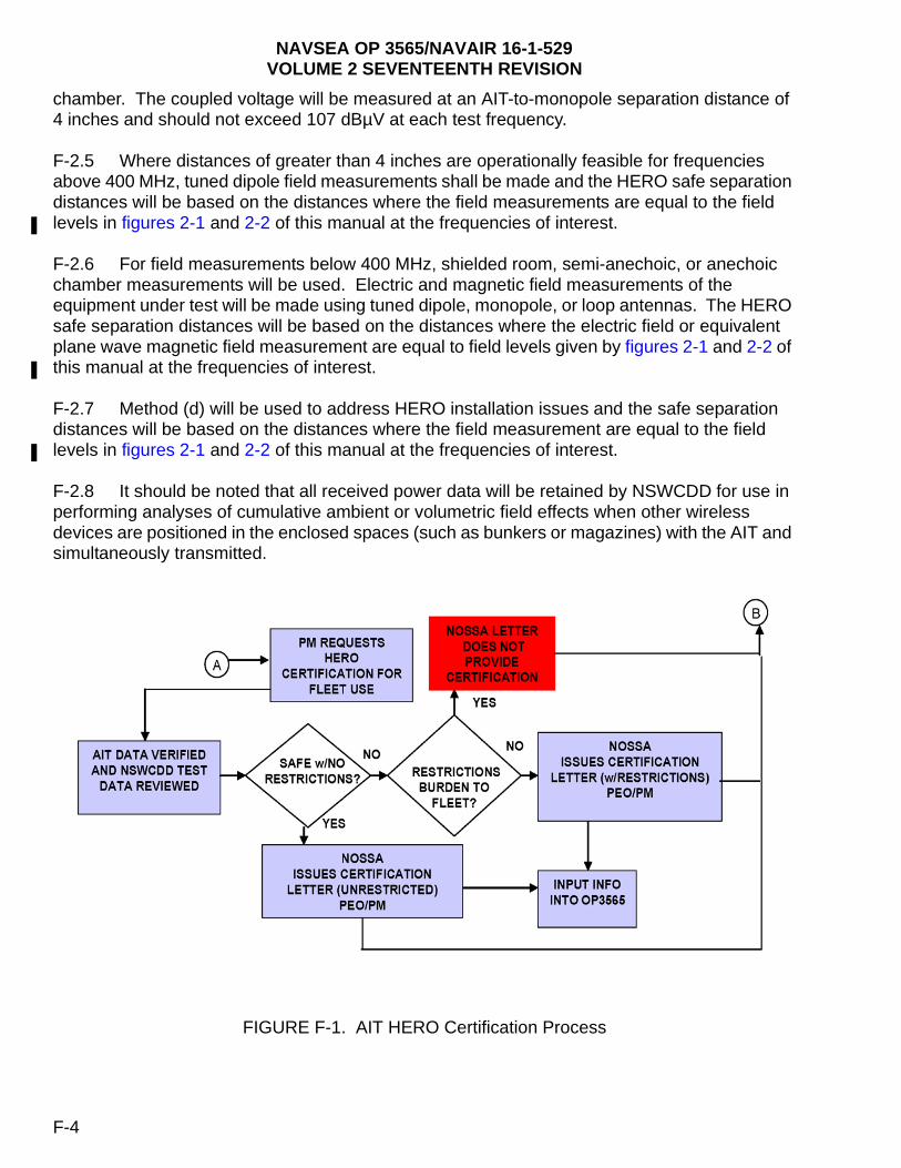
NAVSEA OP 3565/NAVAIR 16-1-529VOLUME 2 SEVENTEENTH REVISION
chamber. The coupled voltage will be measured at an AIT-to-monopole separation distance of 4 inches and should not exceed 107 dBµV at each test frequency.
F-2.5 Where distances of greater than 4 inches are operationally feasible for frequencies above 400 MHz, tuned dipole field measurements shall be made and the HERO safe separation distances will be based on the distances where the field measurements are equal to the field levels in figures 2-1 and 2-2 of this manual at the frequencies of interest.
F-2.6 For field measurements below 400 MHz, shielded room, semi-anechoic, or anechoic chamber measurements will be used. Electric and magnetic field measurements of the equipment under test will be made using tuned dipole, monopole, or loop antennas. The HERO safe separation distances will be based on the distances where the electric field or equivalent plane wave magnetic field measurement are equal to field levels given by figures 2-1 and 2-2 of this manual at the frequencies of interest.
F-2.7 Method (d) will be used to address HERO installation issues and the safe separation distances will be based on the distances where the field measurement are equal to the field levels in figures 2-1 and 2-2 of this manual at the frequencies of interest.
F-2.8 It should be noted that all received power data will be retained by NSWCDD for use in performing analyses of cumulative ambient or volumetric field effects when other wireless devices are positioned in the enclosed spaces (such as bunkers or magazines) with the AIT and simultaneously transmitted.
FIGURE F-1. AIT HERO Certification Process
F-4

NAVSEA OP 3565/NAVAIR 16-1-529VOLUME 2 SEVENTEENTH REVISION
FIGURE F-2. AIT HERO Evaluation Process
F-3. AIT EQUIPMENT SAFE SEPARATION DISTANCES.
Table F-1, “AIT Equipment Safe Separation Distances” has been deleted with Revision Seventeen. The data in this table will be updated to reflect new testing methods and standards, and will be reissued with the next revision to this manual. In the interim, please contact NOSSA (N84) for HERO guidance when using all types of AIT equipment.
F-5/(F-6 Blank)

This page left intentionally blank
Ref: NAVSEAINST 4160.3A NAVSEA S0005-AA-GYD-030/TMMP
NAVSEA/SPAWAR TECHNICAL MANUAL DEFICIENCY/EVALUATION REPORT (TMDER)
INSTRUCTION: Continue on 8 1/2" x 11" paper if additional space is needed.1. Use this report to indicate deficiencies, problems and recommendations relating to publications.2. For CLASSIFIED TMDERs see OPNAVINST 5510H for mailing requirements.3. For TMDERs that affect more than one publication, submit a separate TMDER for each.4. Submit TMDERs at website https://nsdsa2.phdnswc.navy.mil or mail to: COMMANDER, CODE 310 TMDER BLDG 1388, NAVSURFWARCENDIV NSDSA, 4363 MISSILE WAY, PORT HUENEME CA 93043-4307
1. PUBLICATION NUMBER 2. VOL/PART 3. REV. NO./DATE OR TM CH. NO./DATE
4. SYSTEM/EQUIPMENT IDENTIFICATION
NAVSEA OP 3565 2 17TH REV/1 JULY 2008
5. TITLE OF PUBLICATION
ELECTROMAGNETIC RADIATION HAZARDS (U) (HAZARDS TO ORDNANCE) (U)
6. REPORT CONTROL NUMBER(6 digit UIC-yy-any four: xxxxxx-03-xxxx
7. RECOMMENDED CHANGES TO PUBLICATION
7a. Page # 7b. Para # 7c. RECOMMENDED CHANGES AND REASONS
8. ORIGINATOR’S NAME AND WORK CENTER 9. DATE 10. ORIGINATOR’S EMAIL ADDRESS 11. TMMA of Manual(NSDSA will complete)
12. SHIP OR ACTIVITY Name and Address (Include UIC/CAGE/HULL) 13. Phone Numbers: Commercial (____) _____-________
DSN (____) _____-________
FAX (____) _____-________
NAVSEA 4160/1 (Rev. 7-2003) S/N 0116-LF-985-4100
To expedite a response also mail a copy to: Director, Naval Surface Warfare Center, Indian Head Division Detachment Earle, 201 Highway 34 South, Colts Neck, NJ 07722-5023, Attn: Code E421.