this owner's manual should be considered a permanent - honda
TRANSCRIPT

This owner’s manual should be considered a permanent part of the vehicle and should remain with the vehicle when itis sold.
The information and specifications included in this publication were in effect at the time of approval for printing.Honda Motor Co., Ltd. reserves the right, however, to discontinue or change specifications or design at any timewithout notice and without incurring any obligation whatsoever.
Although this manual is applicable to both right-hand and left-hand drive models, the illustrations contained in thismanual mainly refer to the left-hand drive models.Illustrations of vehicles with diesel engine are titled Diesel model.
This owner’s manual covers all versions. Therefore, you may find descriptions of equipment and features that are noton your particular vehicle.
10/09/29 19:28:01 42SWAF30_001

One of the best ways to enhance the enjoyment of your new vehicle is toread this manual. In it, you will learn how to operate its driving controls andconvenience items. Afterwards, keep this owner’s manual in your vehicle soyou can refer to it at any time.
Symbols on labels attached to your vehicle are to remind you toread this owner’s manual for proper and safe operation of your vehicle.
As you read this manual, you willfind information that is preceded bya symbol. Thisinformation is intended to help youavoid damage to your vehicle, otherproperty, or the environment.
(On German type)Mounting the front licence plate:Mount the front licence plate tothe provided holder taking carethat the upper edge of the licenceplate does not project above theupper surface of the bumper.
Mounting the rear licence plate:Mount the rear licence plate to theback of the vehicle so that itslower edge is flush with the lowerend of the surface provided formounting.
Several other booklets explain the warranties that protect your new vehicle.Read the Service Book/warranty booklet thoroughly so you understand thecoverages and are aware of your rights and responsibilities.
Congratulations! Your selection was a wise investment. It will give you yearsof driving pleasure.
Maintaining your vehicle according to the schedules given in this manual orthe separate service information booklet helps to keep your driving trouble-free while it preserves your investment. When your vehicle needsmaintenance, keep in mind that your dealer’s staff is specially trained inservicing the many systems unique to your vehicle. Your dealer is dedicatedto your satisfaction and will be pleased to answer any questions andconcerns.
Best wishes and happy motoring.
1.
2.
Introduction
i
10/09/29 19:28:15 42SWAF30_002

Your vehicle is equipped with several devices commonly referred to as Event Data Recorders. They record varioustypes of real time vehicle data such as SRS airbag deployment and SRS system components failure.Vehicle data is also gathered including crash avoidance information, such as steering operation, brake operation, andvehicle speed, etc.This data belongs to the vehicle owner and may not be accessed by anyone else except as legally required or with thepermission of the vehicle owner.However this data may be accessed by Honda, its authorised dealers and authorised repairers, employees,representatives and contractors only for the purpose of the technical diagnosis, research and development of thevehicle.
Your vehicle is equipped with service-related devices that record information about powertrain performance anddriving conditions. The data can be used to help technicians diagnose, repair and maintain the vehicle. This data maynot be accessed by anyone else except as legally required or with the permission of the vehicle owner.However this data may be accessed by Honda, its authorised dealers and authorised repairers, employees,representatives and contractors only for the purpose of the technical diagnosis, research and development of thevehicle.
Introduction
Event Data Recorders
Service Diagnostic Recorders
ii
10/09/29 19:28:20 42SWAF30_003
--
-
--
-
Your safety, and the safety of others,is very important. And operating thisvehicle safely is an importantresponsibility.
To help you make informeddecisions about safety, we haveprovided operating procedures andother information on labels and inthis manual. This information alertsyou to potential hazards that couldhurt you or others.
Of course, it is not practical orpossible to warn you about all thehazards associated with operating ormaintaining your vehicle. You mustuse your own good judgement.
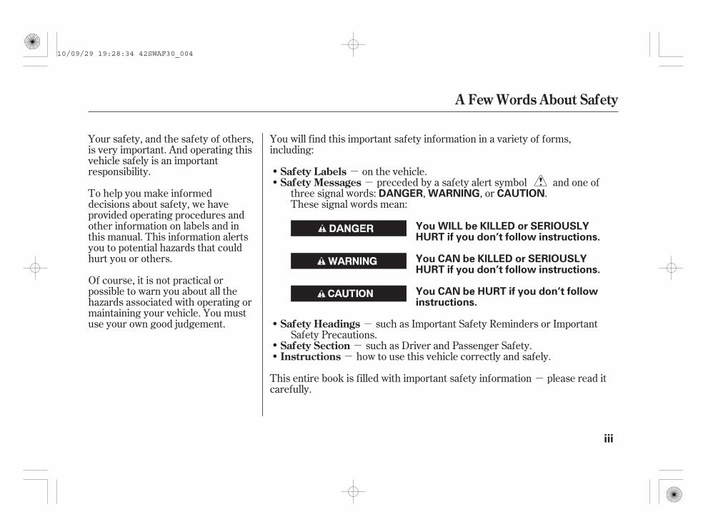
You will find this important safety information in a variety of forms,including:
on the vehicle.preceded by a safety alert symbol and one of
three signal words: , , or .These signal words mean:
such as Important Safety Reminders or ImportantSafety Precautions.
such as Driver and Passenger Safety.how to use this vehicle correctly and safely.
This entire book is filled with important safety information please read itcarefully.
Safety LabelsSafety Messages
Safety Headings
Safety SectionInstructions
A Few Words About Safety
DANGER WARNING CAUTION
You WILL be KILLED or SERIOUSLYHURT if you don’t follow instructions.
You CAN be KILLED or SERIOUSLYHURT if you don’t follow instructions.
You CAN be HURT if you don’t followinstructions.
iii
10/09/29 19:28:34 42SWAF30_004

These advantages come at some cost. Because your vehicle is taller and rides higher off the ground, it has a highcentre of gravity. This means your vehicle can tip or roll over if you make abrupt turns. Utility vehicles have asignificantly higher rollover rate than other types of vehicles. In a rollover crash, an unbelted person is significantlymore likely to die than a person wearing a seat belt. As a reminder, make sure you and your passengers always wearseat belts.
For information on how to reduce the risk of rollover, read ‘‘Driving Guidelines’’ on page of this manual and thesection on page . Failure to operate this vehicle correctly might result in loss of control or an
accident.
In many countries, the law prohibits off-road driving, e.g. driving in forests, trailblazing, etc. Please check your locallaws and regulations before commencing any off-road driving activity.
Your vehicle has higher ground clearance than a passenger vehicle designed for use only on paved roads. Higherground clearance has many advantages for off-road driving. It allows you to travel over bumps, obstacles, and roughterrain. It also provides good visibility so you can anticipate problems earlier.
372421Off-road Guidelines
Important Handling Information
iv
10/09/29 19:28:40 42SWAF30_005

Turn to the beginning of each section for a complete list of subjects.
Explains the purpose of eachinstrument panel indicator,message and symbol on the multi-information display, gauge, andhow to use the controls on thedashboard and steering column.
What fuel to use, how to break-inyour new vehicle, and how to loadluggage and other cargo.
The proper way to start the engine,shift the transmission, and park;plus what you need to know ifyou’re planning to tow a trailer.
The maintenance schedule showsyou when you need to take yourvehicle to the dealer. There is alsoa list of things to check andinstructions on how to check them.
Tips on cleaning and protectingyour vehicle.
This section covers severalproblems motorists sometimesexperience, and details how tohandle them.
ID numbers, dimensions,capacities, and technicalinformation.
Important information about theproper use and care of yourvehicle’s seat belts, an overview ofthe supplemental restraint system,and valuable information on howto protect children with childrestraints.
How to operate the heating and airconditioning system/climatecontrol system, the audio system,and other convenience features.
Contents
..........Your Vehicle at a Glance . 2
....Driver and Passenger Safety . 9
.....Instruments and Controls . 79
............................Features . 225
...................Before Driving . 351
..............................Driving . 371
......................Maintenance . 425
................Appearance Care . 503
Taking Care of the.......................Unexpected . 511
.........Technical Information . 565
................................Index . 581
1
10/09/29 19:28:58 42SWAF30_006

*
*
*
*
*
*
*
*
* If equipped:
Your Vehicle at a Glance
2
Left-hand drive type
POWER WINDOWSWITCHES
POWER DOOR LOCKMASTER SWITCH
FUEL FILL DOORRELEASE HANDLE
BONNET RELEASEHANDLE
CLOCK
DRIVER’S FRONT AIRBAG
Vehicle without navigation system is shown.
MIRROR CONTROLS
MANUALTRANSMISSION
AUTOMATICTRANSMISSION
HEATING/COOLINGCONTROLSCLIMATE CONTROLSYSTEM
ACCESSORYPOWER SOCKET
SEAT HEATERSWITCHES
AUXILIARYINPUT JACK
DOOR LOCKS
AUDIO SYSTEM
USB ADAPTERCABLE
HAZARD WARNINGBUTTON
PASSENGER’SFRONT AIRBAG
(P.15, 35)
(P.210)
(P.164)
(P.164)
(P.203)
(P.101)MULTI-INFORMATION DISPLAY SUNROOF SWITCH (P.205)
SUNSHADE SWITCH (P.207)
(P.156)
(P.15, 35)
(P.274, 282)
(P.243)
(P.216)(P.290)(P.196)
(P.233)
(P.226)
(P.293)
(P.354)
(P.356)
(P.381)
(P.376)
10/09/29 19:29:07 42SWAF30_007

*
**
*
*
*
*
*
*
*
*
*
*
To use the horn, press the centre pad of the steering wheel.If equipped
1 :
3 :2 :
On vehicles with headlight adjuster
Your Vehicle at a Glance
On vehicles without navigation system
3
HORN
INSTRUMENT PANELBRIGHTNESS
Left-hand drive type
VEHICLE STABILITYASSIST (VSA) SYSTEMOFF SWITCH/HEADLIGHTADJUSTER
WINDSCREEN WIPERS/WASHERS
REMOTE AUDIOCONTROLS
STEERING WHEELADJUSTMENTS
CRUISE CONTROLBUTTONS
HEADLIGHT WASHERS
REAR WINDOW DEMISTER/HEATED MIRROR BUTTON
PARKING SENSOR SYSTEM BUTTON
HEADLIGHTS/TURN SIGNALS
MULTI-INFORMATION BUTTONS
(P.148)REAR FOG LIGHT/FRONT FOG LIGHTS (P.150/151)
(P.289)
(P.159)
(P.155)
(P.144)
(P.145)
(P.156/211)
(P.102)(P.154)
ADAPTIVE FRONTLIGHTING SYSTEM(AFS) OFF SWITCH
HAZARD WARNINGBUTTON(P.156)
AUDIO SYSTEM
(P.403/158)
(P.319)
(P.298)
(P.243)
VEHICLE STABILITYASSIST (VSA) SYSTEMOFF SWITCH(P.403)
1
2
2
2
2
2
2
2
2
3
10/09/29 19:29:16 42SWAF30_008

*
*
*
*
*
*
* *
*
*
*
*
***
If equippedTo use the horn, press the centre pad of the steering wheel.
Refer to the navigation system manual.
1 :2 :3 :
Your Vehicle at a Glance
On vehicles with navigation system
4
HEADLIGHTS/TURN SIGNALSLeft-hand drive type
HORN
REAR FOG LIGHT/FRONT FOG LIGHTS
STEERING WHEELADJUSTMENTS
PARKING SENSORSYSTEM BUTTON
DISTANCEBUTTON
REMOTE AUDIO CONTROLBUTTONS
VEHICLE STABILITYASSIST (VSA) SYSTEMOFF SWITCH
ADAPTIVE FRONTLIGHTING SYSTEM (AFS)OFF SWITCH
HANDS-FREE TELEPHONE SYSTEMVOICE CONTROL BUTTONS
NAVIGATION SYSTEM VOICECONTROL BUTTONS CRUISE CONTROL BUTTONS
ADAPTIVE CRUISE CONTROLSYSTEM BUTTONS
MULTI-INFORMATIONBUTTONS
INSTRUMENT PANELBRIGHTNESS
WINDSCREENWIPERS/WASHERS
HEADLIGHT WASHERS
AUDIO SYSTEM
REAR WINDOWDEMISTER/HEATEDMIRROR BUTTON
(P.148)
(P.150/151)
(P.289)
(P.154)
(P.159) (P.102)
(P.156/211)
(P.145)
(P.144)
(P.155)HAZARD WARNING BUTTON(P.156)
COLLISION MITIGATIONBRAKING SYSTEM(CMBS) OFF SWITCH
(P.403)
(P.396)
(P.325)(P.312)
(P.301)
(P.298)
(P.319)
1
2
2
2
2
2
3 2
2
2
3
2
10/09/29 19:29:25 42SWAF30_009

*
*
*
*
*
*
*
*
*
If equipped:
Your Vehicle at a Glance
5
MIRROR CONTROLS
FUEL FILL DOORRELEASE HANDLE
Right-hand drive type
BONNET RELEASEHANDLE
Vehicle without navigation system is shown.
DRIVER’S FRONT AIRBAG
ACCESSORY POWERSOCKET
AUXILIARY INPUT JACK SEAT HEATER SWITCHES
CLIMATE CONTROLSYSTEM
HEATING/COOLINGCONTROLS
MANUAL TRANSMISSION
AUDIO SYSTEM
CLOCK
PASSENGER’SFRONT AIRBAG
HAZARD WARNINGBUTTON
SUNROOF SWITCH
POWER WINDOWSWITCHES
POWER DOOR LOCKMASTER SWITCH
DOOR LOCKS
USB ADAPTER CABLE
SUNSHADE SWITCH
AUTOMATIC TRANSMISSION
(P.156)
(P.15, 35)
(P.274, 282)
(P.243)
(P.290)(P.216) (P.196)
(P.203)
(P.164)
(P.164)
(P.210)
(P.15, 35)(P.207)MULTI-INFORMATIONDISPLAY (P.101)
(P.205)
(P.226)
(P.233)
(P.293)
(P.376)
(P.381)
(P.356)
(P.354)
10/09/29 19:29:33 42SWAF30_010

***
*
*
*
*
*
*
*
*
*
*
*
To use the horn, press the centre pad of the steering wheel.If equipped
1 :2 :3 : On vehicles with headlight adjuster
Your Vehicle at a Glance
On vehicles without navigation system
6
Right-hand drive type
HEADLIGHT WASHERS
PARKING SENSOR SYSTEMBUTTON
REAR WINDOW DEMISTER/HEATED MIRROR BUTTON
HEADLIGHTS/TURN SIGNALSREAR FOG LIGHT/FRONT FOG LIGHTS
VEHICLE STABILITYASSIST (VSA) SYSTEMOFF SWITCH/HEADLIGHTADJUSTER
WINDSCREENWIPERS/WASHERS
CRUISE CONTROLBUTTONS
ADAPTIVE FRONTLIGHTING SYSTEM(AFS) OFF SWITCH
REMOTE AUDIO CONTROLS MULTI-INFORMATIONBUTTONS
INSTRUMENT PANEL BRIGHTNESS
(P.145)
(P.156/211)
(P.150/151)
(P.148)(P.155)
(P.144)
(P.154)
STEERING WHEELADJUSTMENTS(P.159)
(P.289)
HAZARD WARNINGBUTTON(P.156)
AUDIO SYSTEM(P.243)
(P.319)
(P.403/158)
(P.298)
VEHICLE STABILITY ASSIST(VSA) SYSTEM OFF SWITCH
(P.102) (P.403)
HORN
2
2
2
2
2
2
2
2
2
3
1
10/09/29 19:29:41 42SWAF30_011

*
*
*
*
*
*
*
*
*
*
*
*
***
If equippedTo use the horn, press the centre pad of the steering wheel.
Refer to the navigation system manual.
1 :2 :3 :
Your Vehicle at a Glance
On vehicles with navigation system
7
Right-hand drive type
DISTANCE BUTTON
INSTRUMENT PANELBRIGHTNESS
HORN
HAZARD WARNINGBUTTON
HANDS-FREE TELEPHONESYSTEM VOICE CONTROLBUTTONS
HEADLIGHTS/TURN SIGNALS
VEHICLE STABILITY ASSIST(VSA) SYSTEM OFF SWITCH
ADAPTIVE FRONTLIGHTING SYSTEM (AFS)OFF SWITCH
CRUISE CONTROLBUTTONSADAPTIVE CRUISE CONTROLSYSTEM BUTTONS
WINDSCREEN WIPERS/WASHERS
MULTI-INFORMATIONBUTTONS
(P.148)
(P.150/151)
(P.289)
STEERING WHEELADJUSTMENTS(P.159)
(P.156) (P.155) (P.144)
(P.154)
(P.102)
COLLISION MITIGATIONBRAKING SYSTEM (CMBS)OFF SWITCH
REAR FOG LIGHT/FRONTFOG LIGHTS
REMOTE AUDIO CONTROLBUTTONS
AUDIO SYSTEM
HEADLIGHT WASHERS(P.145)
PARKING SENSOR SYSTEMBUTTON
REAR WINDOW DEMISTER/HEATED MIRROR BUTTON(P.156/211)
NAVIGATION SYSTEM VOICECONTROL BUTTONS
(P.319)
(P.325) (P.312)
(P.301)
(P.298)
(P.396)
(P.403)
2
1
2
2
2
2
2
2
3
2
2
3
10/09/29 19:29:50 42SWAF30_012

8
10/09/29 19:29:52 42SWAF30_013

-
This section gives you importantinformation about how to protectyourself and your passengers. Itshows you how to use seat belts. Itexplains how your airbags work. Andit tells you how to properly restraininfants and children in your vehicle.
.......Important Safety Precautions . 10.....Your Vehicle’s Safety Features . 12
.....................................Seat Belts . 13.........................................Airbags . 15
.........Protecting Adults and Teens . 17......................1. Close the Doors . 17
...........2. Adjust the Front Seats . 18............3. Adjust the Seat-Backs . 19
...4. Adjust the Head Restraints . 205. Fasten and Position the Seat
.....................................Belts . 216. Maintain a Proper Sitting
................................Position . 23.....Advice for Pregnant Women . 24...Additional Safety Precautions . 24
Additional Information About Your.................................Seat Belts . 26
..Seat Belt System Components . 26
......................Lap/Shoulder Belt . 29Automatic Seat Belt
...............................Tensioners . 31...........Seat Belt e-pretensioners . 32
...............Seat Belt Maintenance . 33Additional Information About
...........................Your Airbags . 35......Airbag System Components . 35
How Your Front Airbags.........................................Work . 36
...How Your Side Airbags Work . 38How Your Side Curtain
..........................Airbags Work . 38..How the SRS Indicator Works . 39
.............................Airbag Service . 41...Additional Safety Precautions . 41
Protecting Children General................................Guidelines . 42
All Children Must Be...............................Restrained . 42
All Children Should Sit in a.................................Back Seat . 43
The Passenger’s Front Airbag................Poses Serious Risks . 43
The Side Airbag Poses Serious.........................................Risks . 46
If You Must Drive with Several...................................Children . 47
If a Child Requires Close..................................Attention . 47
...Additional Safety Precautions . 47Protecting Infants and Small
...................................Children . 49.......................Protecting Infants . 49
.........Protecting Small Children . 51Selecting a Child Restraint
..........................................System . 53Installing a Child Restraint
......................................System . 55Child Restraint System for EU
.................................Countries . 56....With the Lower Anchorages . 58
.........With a Lap/Shoulder Belt . 63..............................With a Tether . 68
...........Protecting Larger Children . 71...............Checking Seat Belt Fit . 72
..................Using a Booster Seat . 72When Can a Larger Child Sit in
.........................................Front . 74...Additional Safety Precautions . 75
.............Carbon Monoxide Hazard . 76...................................Safety Labels . 77
Driver and Passenger Safety
Driver and Passenger Safety 9
10/09/29 19:29:58 42SWAF30_014

-
You’ll find many safetyrecommendations throughout thissection, and throughout this manual.The following recommendations arethe ones we consider to be the mostimportant.
While airbags can save lives, theycan cause serious or fatal injuries tooccupants who sit too close to them,or are not properly restrained.Infants, young children, and shortadults are at the greatest risk. Besure to follow all instructions andwarnings in this manual.
Alcohol and driving don’t mix. Evenone drink can reduce your ability torespond to changing conditions, andyour reaction time gets worse withevery additional drink. So don’t drinkand drive, and don’t let your friendsdrink and drive, either.
A seat belt is your best protection inall types of collisions. Airbags aredesigned to supplement seat belts,not replace them. So even thoughyour vehicle is equipped with airbags,make sure you and your passengersalways wear your seat belts, andwear them properly (see page ).
Children age 12 and under shouldride properly restrained in a backseat, not the front seat. Infants andsmall children should be restrainedin a child restraint system. Largerchildren should use a booster seatand a lap/shoulder belt until theycan use the belt properly without abooster seat (see pages ).
21
42 75
Important Safety Precautions
Driver and Passenger Safety
Be Aware of Airbag Hazards
Don’t Drink and Drive
Always Wear Your Seat Belt
Restrain All Children
10
10/09/29 19:30:09 42SWAF30_015

Engaging in mobile phoneconversation or other activities thatkeep you from paying close attentionto the road, other vehicles andpedestrians could lead to a crash.Remember, situations can changequickly, and only you can decidewhen it is safe to divert attentionaway from driving.
Excessive speed is a major factor incrash injuries and deaths. Generally,the higher the speed, the greater therisk, but serious injuries can alsooccur at lower speeds. Never drivefaster than is safe for currentconditions, regardless of themaximum speed posted.
Having a tyre blowout or amechanical failure can be extremelyhazardous. To reduce the possibilityof such problems, check your tyrepressures and condition frequently,and perform all regularly scheduledmaintenance (see page , and forEU countries and South Africa, seethe separate service informationbooklet that came with your vehicle).
429
Pay Appropriate Attention to theTask of Driving Safely
Control Your Speed
Keep Your Vehicle in SafeCondition
Driver and Passenger Safety
Important Safety Precautions
11
10/09/29 19:30:17 42SWAF30_016

* *
Your vehicle is equipped with manyfeatures that work together toprotect you and your passengersduring a crash.
However, you and your passengerscan’t take full advantage of thesefeatures unless you remain sitting inthe correct position and
. In fact, some safetyfeatures can contribute to injuries ifthey are not used properly.
The following pages explain how youcan take an active role in protectingyourself and your passengers.
Some features do not require anyaction on your part. These include astrong steel framework that forms asafety cage around the passengercompartment, front and rear crushzones, a collapsible steering column,and tensioners that tighten the frontseat belts in a crash.
always wearyour seat belts
Your Vehicle’s Safety Features
Driver and Passenger Safety12
(2)
(2)
(5)
(1)(3) (4) (9) (9)
(11)
(7)
(11)
(10)(8)
(6)
(11) Outer Lap Tensioners
(1) Safety Cage(2) Crush Zones(3) Seats and Seat-Backs(4) Head Restraints(5) Collapsible Steering Column
:
(6) Seat Belts(7) Front Airbags(8) Side Airbags(9) Side Curtain Airbags(10) Front Seat Belt Tensioners/
Seat Belt e-pretensionersOn vehicles with collisionmitigation braking system (CMBS)
10/09/29 19:30:26 42SWAF30_017
----
Your vehicle is equipped with seatbelts in all seating positions.
Seat belts are the single mosteffective safety device for adults andlarger children. (Infants and smallerchildren must be properly restrainedin child restraint systems.)
Not wearing a seat belt properlyincreases the chance of seriousinjury or death in a crash, eventhough your vehicle has airbags.
In most European Countries there isa law covering the use of seat belts.Please take time to familiarizeyourself with the legal requirementsof the countries in which you willdrive.
When properly worn, seat belts:
Your seat belt system also includesan indicator on the instrument paneland a beeper to remind you and yourpassengers to fasten your seat belts.
Keep you connected to the vehicleso you can take advantage of thevehicle’s built-in safety features.
Help protect you in almost everytype of crash, including:
frontal impactsside impactsrear impactsrollovers
Help keep you from being thrownagainst the inside of the vehicleand against other occupants.
Keep you from being thrown outof the vehicle.
Help keep you in a good positionshould the airbags ever deploy. Agood position reduces the risk ofinjury from an inflating airbag andallows you to get the bestadvantage from the airbag.
CONTINUED
Seat Belts
Why Wear Seat Belts
Your Vehicle’s Safety Features
Driver and Passenger Safety 13
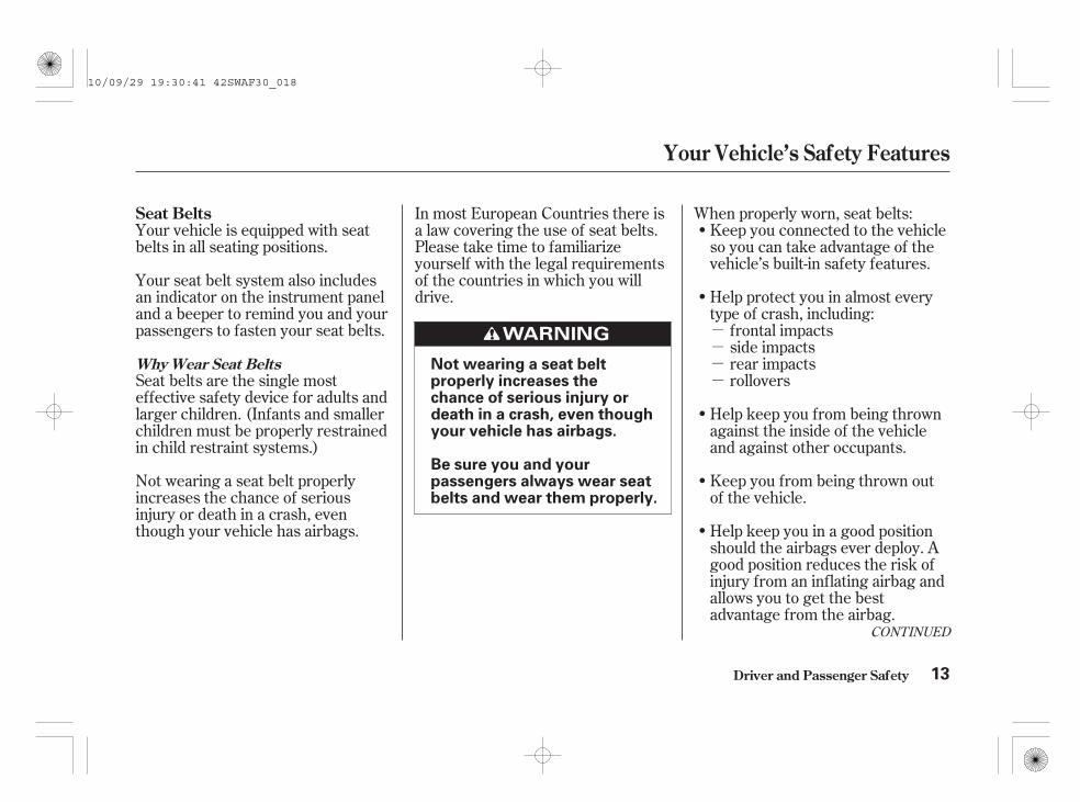
Not wearing a seat beltproperly increases thechance of serious injury ordeath in a crash, even thoughyour vehicle has airbags.
Be sure you and yourpassengers always wear seatbelts and wear them properly.
10/09/29 19:30:41 42SWAF30_018

Of course, seat belts cannotcompletely protect you in everycrash. But in most cases, seat beltscan reduce your risk of seriousinjury.
Always wear your seat belt, andmake sure you wear it properly.
Seat belts are designed to bear uponthe bony structure of the body, andshould be worn low across the frontof the pelvis or the pelvis, chest andshoulders, as applicable; wearing thelap section of the belt across theabdominal area must be avoided.
Seat belts should be adjusted asfirmly as possible, consistent withcomfort, to provide the protection forwhich they have been designed. Aslack belt will greatly reduce theprotection afforded to the wearer.
Belts should not be worn with strapstwisted.
Each belt assembly must only be usedby one occupant; it is dangerous toput a belt around a child being carriedon the occupant’s lap.
What You Should Do:
Your Vehicle’s Safety Features
Driver and Passenger Safety14
WARNING:
10/09/29 19:30:51 42SWAF30_019

Your vehicle has a supplementalrestraint system (SRS) with frontairbags to help protect the heads andchests of the driver and a front seatpassenger during a moderate tosevere frontal collision (see page
for more information on howyour front airbags work).
Your vehicle also has side airbags tohelp protect the upper torso of thedriver or a front seat passengerduring a moderate to severe sideimpact (see page for moreinformation on how your side airbagswork).
In addition, your vehicle has sidecurtain airbags to help protect theheads of the driver, front passenger,and passengers in the outer rearseating positions during a moderateto severe side impact or rollover (seepage for more information on howyour side curtain airbags work).
38
3836
CONTINUED
Airbags
Your Vehicle’s Safety Features
Driver and Passenger Safety 15
10/09/29 19:31:00 42SWAF30_020

The most important things you needto know about your airbags are:
They are designed to supplementthe seat belts.
Always wearyour seat belt properly, and situpright and as far back from thesteering wheel as possible whileallowing full control of the vehicle. Afront passenger should move theirseat as far back from the dashboardas possible.
The rest of this section gives moredetailed information about how youcan maximize your safety.
Remember, however, that no safetysystem can prevent all injuries ordeaths that can occur in a severecrash, even when seat belts areproperly worn and the airbags deploy.
To do their job, airbags mustinflate with tremendous force. Sowhile airbags help save lives, theycan cause minor injuries or moreserious or even fatal injuries ifoccupants are not properlyrestrained or sitting properly.
Airbags do not replace seat belts.
Airbags offer no protection in rearcollisions, or minor frontal or sidecollisions.
What you should do:
Airbags can pose serious hazards.
Your Vehicle’s Safety Features
Driver and Passenger Safety16
10/09/29 19:31:09 42SWAF30_021

-
The following pages provideinstructions on how to properlyprotect the driver, adult passengers,and teenage children who are largeenough and mature enough to driveor ride in the front.
See pages for importantguidelines on how to properlyprotect infants, small children, andlarger children who ride in yourvehicle.
After everyone has entered thevehicle, be sure the doors and thetailgate are closed.
Your vehicle also has a door andtailgate open indicator on the multi-information display to indicate whena specific door or the tailgate is nottightly closed. You will see theappropriate indicator(s) for eachcondition.
The above illustration shows that alldoors and the tailgate are open.
You will also hear a beep when youturn the ignition switch to the ON(II) position, and each time you openany door or the tailgate with the keyin the ON (II) position.
42 48
CONTINUED
Introduction Close the Doors1.
Driver and Passenger Safety
Protecting Adults and Teens
17
10/09/29 19:31:21 42SWAF30_022

Adjust the driver’s seat as far to therear as possible while allowing you tomaintain full control of the vehicle.Have a front passenger adjust theirseat as far to the rear as possible.
If you sit too close to the steeringwheel or dashboard, you can beseriously injured by an inflating frontairbag, or by striking the steeringwheel or dashboard.
When the tailgate is not tightlyclosed, this indicator will come on.
When one or more doors or thetailgate are not tightly closed, thecorresponding indicator for eachcondition will come on.
Adjust the Front Seats2.
Protecting Adults and Teens
Driver and Passenger Safety18
This shows the front right and rear leftdoors and the tailgate open.
10/09/29 19:31:30 42SWAF30_023

In addition to adjusting the seat, youcan adjust the steering wheel up anddown, and in and out (see page ).
If you cannot get far enough awayfrom the steering wheel and stillreach the controls, we recommendthat you investigate whether sometype of adaptive equipment may help.
Once a seat is adjusted correctly,rock it back and forth to make sure itis locked in position.
See page for how to adjust afront seat (power adjustment) andpage for a manual adjustment.
Adjust the driver’s seat-back to acomfortable, upright position,leaving ample space between yourchest and the airbag cover in thecentre of the steering wheel.
Passengers with adjustable seat-backs should also adjust their seat-back to a comfortable, uprightposition.
159
181
182
On vehicles with manual adjustableseats
CONTINUED
Protecting Adults and Teens
Driver and Passenger Safety
Adjust the Seat-Backs3.
19
Sitting too close to a frontairbag can result in seriousinjury or death if the frontairbags inflate.
Always sit as far back fromthe front airbags as possible.
10/09/29 19:31:43 42SWAF30_024

Adjust the driver’s head restraint sothe centre of the back of your headrests against the centre of therestraint.
Have passengers adjust their headrestraints properly as well. Tallerpersons should adjust their restraintas high as possible.
Reclining a seat-back so that theshoulder part of the belt no longerrests against the occupant’s chestreduces the protective capability ofthe belt. It also increases the chanceof sliding under the belt in a crashand being seriously injured. Thefarther a seat-back is reclined, thegreater the risk of injury.
See page for how to adjust themanual adjustable seat-back, andpage for the power adjustableseat-back.
182
181
Protecting Adults and Teens
Driver and Passenger Safety
Adjust the Head Restraints4.
20
Reclining the seat-back toofar can result in serious injuryor death in a crash.
Adjust the seat-back to anupright position, and sit wellback in the seat.
10/09/29 19:31:52 42SWAF30_025

Properly adjusted head restraintswill help protect occupants fromwhiplash and other crash injuries. Insert the latch plate into the buckle,
then tug on the belt to make sure thebelt is securely latched. Check thatthe belt is not twisted, because atwisted belt can cause seriousinjuries in a crash.
The seat belt in the centre positionof the back seat can be unlatchedand retracted to allow the back seatto be folded up or down. This seatbelt should be latched whenever theseat-back is in an upright position.See page for how to unlatch andrelatch the seat belt.
See page for how to adjust thehead restraints and how the driver’sand front passenger’s active headrestraints work.
When a passenger is seated in therear seating position, make sure therear head restraint is adjusted to itshighest position.
185
194
CONTINUED
Protecting Adults and Teens
Driver and Passenger Safety
Fasten and Position the SeatBelts
5.
21
Improperly positioning headrestraints reduces theireffectiveness and you can beseriously injured in a crash.
Make sure head restraints arein place and positionedproperly before driving.
10/09/29 19:32:03 42SWAF30_026

Position the lap part of the belt aslow as possible across your hips,then pull up on the shoulder part ofthe belt so the lap part fits snugly.This lets your strong pelvic bonestake the force of a crash and reducesthe chance of internal injuries.
If necessary, pull up on the belt againto remove any slack, then check thatthe belt rests across the centre ofyour chest and over your shoulder.
This spreads the forces of a crashover the strongest bones in yourupper body.
If the seat belt touches or crossesyour neck, or if it crosses your arminstead of your shoulder, you need toadjust the seat belt anchor height.
The front seats have adjustable seatbelt anchors. To adjust the height ofan anchor, press and hold the releasebuttons, and slide the anchor up ordown as needed (it has fourpositions).
Driver and Passenger Safety
Protecting Adults and Teens
22
Improperly positioning theseat belts can cause seriousinjury or death in a crash.
Make sure all seat belts areproperly positioned beforedriving.
RELEASE BUTTONS
10/09/29 19:32:13 42SWAF30_027

After all occupants have adjustedtheir seats and head restraints, andput on their seat belts, it is veryimportant that they continue to situpright, well back in their seats, withtheir feet on the floor, until thevehicle is safely parked and theengine is off.
This could causevery serious injuries in a crash.
If a seat belt does not seem to workas it should, it may not protect theoccupant in a crash.
Using a seatbelt that is not working properly canresult in serious injury or death.Have your dealer check the belt assoon as possible.
See page for additionalinformation about your seat beltsand how to take care of them.
If a front passenger leans sidewaysand his head is in the deploymentpath of the side airbag, an inflatingside airbag can strike the passengerwith enough force to very seriouslyinjure him.
In addition, an occupant who is out ofposition in the front seat can beseriously or fatally injured in a crashby striking interior parts of thevehicle or being struck by aninflating front airbag.
Sitting improperly can increase thechance of injury during a crash. Forexample, if an occupant slouches,lies down, turns sideways, sitsforward, leans forward or sideways,or puts one or both feet up, thechance of injury during a crash isgreatly increased.
26
Protecting Adults and Teens
Driver and Passenger Safety
Maintain a Proper SittingPosition
6.Never place the shoulder portion of alap/shoulder belt under your arm orbehind your back.
No one should sit in a seat with aninoperative seat belt.
23
Sitting improperly or out ofposition can result in seriousinjury or death in a crash.
Always sit upright, well backin the seat, with your feet onthe floor.
10/09/29 19:32:25 42SWAF30_028

If you are pregnant, the best way toprotect yourself and your unbornchild when driving or riding in avehicle is to always wear a seat belt,and keep the lap part of the belt aslow as possible across the hips.
When driving, remember to situpright and adjust the seat as farback as possible while allowing fullcontrol of the vehicle. When ridingas a front passenger, adjust the seatas far back as possible.
This will reduce the risk of injuriesto both you and your unborn childthat can be caused by a crash or aninflating front airbag.
Each time you have a checkup, askyour doctor if it’s okay for you todrive.
A passenger who is notwearing a seat belt during a crashor emergency stop can be thrownagainst the inside of the vehicle,against other occupants, or out ofthe vehicle.
If they do, theycould be very seriously injured in acrash.
If they do, theycould be very seriously injured in acrash.
Advice for Pregnant Women Additional Safety Precautions
Protecting Adults and Teens
Driver and Passenger Safety
Passengers should not stand up orchange seats while the vehicle ismoving.
Two people should never use thesame seat belt.
Never let passengers ride in theluggage area or on top of a folded-down back seat.
24
10/09/29 19:32:37 42SWAF30_029

Devices intended to improveoccupant comfort or reposition theshoulder part of a seat belt canreduce the protective capability ofthe seat belt and increase thechance of serious injury in a crash.
Carrying hard or sharpobjects on your lap, or driving witha pipe or other sharp object inyour mouth, can result in injuriesif your front airbag inflates.
If yourhands or arms are close to anairbag cover, they could be injuredif the airbag inflates.
Objects onthe covers marked ‘‘SRS AIRBAG’’could interfere with the properoperation of the airbags or bepropelled inside the vehicle andhurt someone if the airbags inflate.
If a side airbag or aside curtain airbag inflates, a cupholder or other hard objectattached on or near the door couldbe propelled inside the vehicle andhurt someone.
This couldresult in injuries if your sidecurtain airbags inflate.
Improperly replacingor covering front seat-back coverscan prevent your side airbags frominflating during a side impact.
Protecting Adults and Teens
Driver and Passenger Safety
Do not put any accessories on seatbelts.
Do not place hard or sharp objectsbetween yourself and a frontairbag.
Keep your hands and arms awayfrom the airbag covers.
Do not attach or place objects onthe front airbag covers.
Do not attach hard objects on ornear a door.
Do not put a coat hanger or hardobjects on a coat hook.
Do not cover or replace front seat-back covers without consultingyour dealer.
25
10/09/29 19:32:47 42SWAF30_030

Your seat belt system includes lap/shoulder belts in all seating positions.The front seat belts are alsoequipped with automatic seat belttensioners.
If you turn the ignition switch to theON (II) position before your seatbelt is fastened, the beeper willsound and the indicator will flash. Ifyour seat belt is not fastened beforethe beeper stops, the indicator willstop flashing but remain on.
If a front passenger does not fastentheir seat belt, the indicator willcome on about 6 seconds after theignition switch is turned to the ON(II) position.
If either the driver or a frontpassenger does not fasten their seatbelt while driving, the beeper willsound and the indicator will flashagain at regular intervals.
The seat belt systemincludes an indicator on the
instrument panel and a beeper toremind you and your passengers tofasten your seat belts.
On vehicles with collision mitigationbraking system (CMBS), the frontseat belts are also equipped with seatbelt e-pretensioners.
This system monitors the seat beltsin all seating positions.
When no one is sitting in the frontpassenger’s seat, or a child or smalladult is riding there, the indicatorshould not come on and the beepershould not sound.
In addition to the seat belt reminderindicator in the instrument panel,you will also see the symbol ‘‘ ,’’or this symbol with a ‘‘FASTENSEAT BELT’’ message if you do notfasten the seat belt while driving.This symbol/message remainsdisplayed if you ignore it and do notfasten the seat belt while the vehicleis moving.
You will also see the symbol ‘‘ ,’’or this symbol with a ‘‘FASTENPASSENGER SEAT BELT’’ messageif a front seat passenger does notfasten their seat belt while driving.This symbol/message remainsdisplayed if a passenger ignores itand does not fasten the seat beltwhile the vehicle is moving.
Additional Information About Your Seat Belts
Driver and Passenger Safety
Seat Belt System Components
26
10/09/29 19:32:59 42SWAF30_031

Have your vehicle checked by adealer if the indicator comes on orthe beeper sounds when there is nofront passenger or there are noobjects on the front seat.
The seat belt system also monitorsthe seat belt use of all three rearseating positions according to theactivation of each seat belt retractor.
When you turn the ignition switch tothe ON (II) position, the multi-information display shows the rearseat belt use by pressing the INFObutton ( ) repeatedly.
The front passenger’s seat belt usemonitoring system uses the occupantdetection sensor in the frontpassenger’s seat. The system maynot work properly under theseconditions:
You place heavy items on the frontpassenger’s seat.
You place a cushion on the frontpassenger’s seat.
The front passenger is not sittingproperly.
CONTINUED
Rear Seat Belt Use Monitor
Additional Information About Your Seat Belts
Driver and Passenger Safety 27
10/09/29 19:33:12 42SWAF30_032

The current display will beinterrupted and the rear seat beltmonitor will also be displayed on themulti-information display if eitherrear door is opened and closed, orany of the rear passengers latchestheir seat belt.
This monitor goes off after about 30seconds. It will also go off when youchange the display by pressing theINFO button ( ) on the steeringwheel.
While driving, you can also confirmthe rear seat belt use. Press andrelease the INFO button ( )repeatedly to change the display.
The seat belt system detects anyseat belt use of all three rear seatseating positions according to theactivation of each seat belt retractor.
The system shows you how manyrear seat belts are being used andreminds you and your passengers tofasten their seat belts. According tothe rear seat belt use (1 through 3),you will see the indicator(s)highlighted on the multi-informationdisplay.
Driver and Passenger Safety
Additional Information About Your Seat Belts
28
The rear seat belt monitorsystem judges the use of therear seat belt based on theamount of seat belt pulledout from the retractor. It isnot an indicator to show thatthe rear seat belt is actuallylatched. Correct latching ofthe seat belts should beconfirmed whenever theindicator shows a rear seatbelt is in use.
Seat belts in right and centrepositions are used.
10/09/29 19:33:23 42SWAF30_033
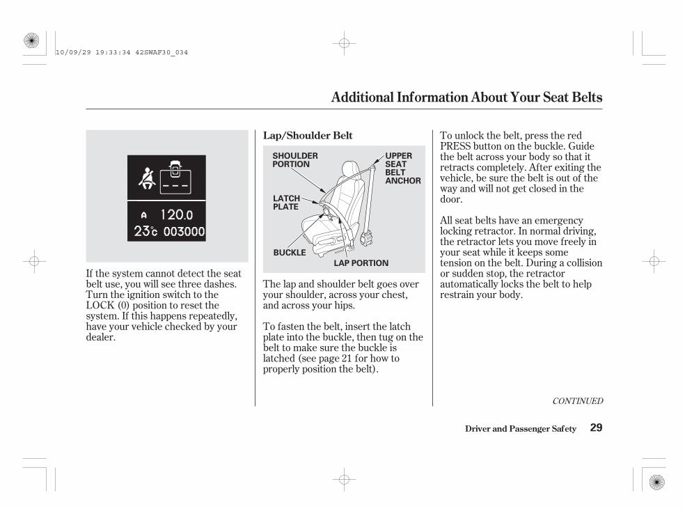
The lap and shoulder belt goes overyour shoulder, across your chest,and across your hips.
To fasten the belt, insert the latchplate into the buckle, then tug on thebelt to make sure the buckle islatched (see page for how toproperly position the belt).
To unlock the belt, press the redPRESS button on the buckle. Guidethe belt across your body so that itretracts completely. After exiting thevehicle, be sure the belt is out of theway and will not get closed in thedoor.
All seat belts have an emergencylocking retractor. In normal driving,the retractor lets you move freely inyour seat while it keeps sometension on the belt. During a collisionor sudden stop, the retractorautomatically locks the belt to helprestrain your body.
If the system cannot detect the seatbelt use, you will see three dashes.Turn the ignition switch to theLOCK (0) position to reset thesystem. If this happens repeatedly,have your vehicle checked by yourdealer.
21
CONTINUED
Lap/Shoulder Belt
Additional Information About Your Seat Belts
Driver and Passenger Safety 29
UPPERSEATBELTANCHOR
BUCKLE
SHOULDERPORTION
LATCHPLATE
LAP PORTION
10/09/29 19:33:34 42SWAF30_034

The seat belts in all rear seatingpositions have a lockable retractorthat must be activated to secure achild restraint (see page ).
If the shoulder part of the belt ispulled all the way out, the lockableretractor will activate. The belt willretract, but it will not allow thepassenger to move freely.
To deactivate the lockable retractor,unlatch the buckle and let the seatbelt fully retract. To refasten theseat belt, pull it out only as far asneeded.
The lap/shoulder belt in the centreseating position on the rear seat isequipped with a detachable seat beltthat has two parts: a small latch plateand an anchor buckle.
The detachable seat belt shouldnormally be latched whenever theseat-backs are in an upright position.For more information about thedetachable seat belt, see page .
64
194
Additional Information About Your Seat Belts
Driver and Passenger Safety30
Using the seat belt with thedetachable anchor unlatchedincreases the chance ofserious injury or death in acrash.
Before using the seat belt,make sure the detachableanchor is correctly latched.
DETACHABLE SEAT BELT
10/09/29 19:33:42 42SWAF30_035

If there is no passenger on the frontpassenger’s seat and the seat belt isnot fastened, the front passenger’sautomatic seat belt tensioner will notbe activated.
The SRS indicator willcome on if there is a
problem with your automatic seatbelt tensioners (see page ).
The tensioners can also be activatedduring a collision in which the frontairbags . In this case, theairbags would not be needed, but theextra tension in the seat belt couldbe helpful.
When the tensioners are activated,the seat belts will remain tight untilthey are unbuckled.
The tensioners are designed toactivate in any collision severeenough to cause the front airbags todeploy, or if a sensor detects yourvehicle is about to roll over (see page
).
If a side curtain airbag deploysduring a side impact, the tensioneron that side of the vehicle will alsodeploy.
For added protection, the front seatbelts are equipped with automaticseat belt tensioners. When activated,the tensioners immediately tightenthe belts to help hold the driver anda front passenger in position.
39
39
do not deploy
On vehicles with collision mitigationbraking system (CMBS)
Additional Information About Your Seat Belts
Driver and Passenger Safety
Automatic Seat Belt Tensioners
31
OUTER LAP TENSIONER
SEAT BELT TENSIONER
10/09/29 19:33:54 42SWAF30_036
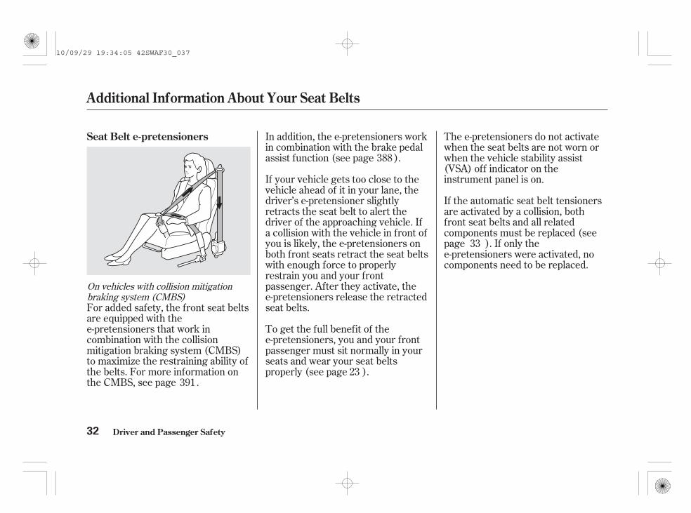
For added safety, the front seat beltsare equipped with thee-pretensioners that work incombination with the collisionmitigation braking system (CMBS)to maximize the restraining ability ofthe belts. For more information onthe CMBS, see page .
In addition, the e-pretensioners workin combination with the brake pedalassist function (see page ).
If your vehicle gets too close to thevehicle ahead of it in your lane, thedriver’s e-pretensioner slightlyretracts the seat belt to alert thedriver of the approaching vehicle. Ifa collision with the vehicle in front ofyou is likely, the e-pretensioners onboth front seats retract the seat beltswith enough force to properlyrestrain you and your frontpassenger. After they activate, thee-pretensioners release the retractedseat belts.
To get the full benefit of thee-pretensioners, you and your frontpassenger must sit normally in yourseats and wear your seat beltsproperly (see page ).
The e-pretensioners do not activatewhen the seat belts are not worn orwhen the vehicle stability assist(VSA) off indicator on theinstrument panel is on.
If the automatic seat belt tensionersare activated by a collision, bothfront seat belts and all relatedcomponents must be replaced (seepage ). If only thee-pretensioners were activated, nocomponents need to be replaced.
23
33
391
388
On vehicles with collision mitigationbraking system (CMBS)
Seat Belt e-pretensioners
Additional Information About Your Seat Belts
Driver and Passenger Safety32
10/09/29 19:34:05 42SWAF30_037

For safety, you should check thecondition of your seat belts regularly.
If a seat belt is worn during a crash,it must be replaced by the dealer. Abelt that has been worn during acrash may not provide the same levelof protection in a subsequent crash.Pull each belt out fully, and look for
frays, cuts, burns, and wear. Checkthat the latches work smoothly andthe belts retract easily. If a belt doesnot retract easily, cleaning the beltmay correct the problem (see page
). Any belt that is not in goodcondition or working properly willnot provide good protection andshould be replaced as soon aspossible.
The dealer should also inspect theanchors for damage and replacethem if needed. If the automatic seatbelt tensioners activate during acrash, they must be replaced.509
It is essential to replacethe entire assembly after it has beenworn in a severe impact even if damageto the assembly is not obvious.
Care should be taken toavoid contamination of the webbing withpolishes, oils and chemicals, andparticularly battery acid. Cleaning maysafely be carried out using mild soap andwater. The belt should be replaced ifwebbing becomes frayed, contaminatedor damaged.
No modifications oradditions should be made by the userwhich will either prevent the seat beltadjusting devices from operating toremove slack, or prevent the seat beltassembly from being adjusted to removeslack.
CONTINUED
Seat Belt Maintenance
Additional Information About Your Seat Belts
Driver and Passenger Safety 33
WARNING:
WARNING:
WARNING:
10/09/29 19:34:16 42SWAF30_038

(Rear Seat)
The rear seat has three lap/shoulderbelts.
When replacing the seat belts, makecertain to use the anchorage pointsshown in the illustrations.
(Front Seat)
Additional Information About Your Seat Belts
Driver and Passenger Safety
Anchorage Points
34
Not checking or maintainingseat belts can result inserious injury or death if theseat belts do not workproperly when needed.
Check your seat beltsregularly and have anyproblem corrected as soon aspossible.
10/09/29 19:34:25 42SWAF30_039

Your airbag system includes:
Two SRS (supplemental restraintsystem) front airbags. The driver’sairbag is stored in the centre ofthe steering wheel; the frontpassenger’s airbag is stored in thedashboard. Both are marked ‘‘SRSAIRBAG’’ (see page ).
Two side airbags, one for thedriver and one for a frontpassenger. The airbags are storedin the outer edges of the seat-backs. Both are marked ‘‘SIDEAIRBAG’’ (see page ).
Two side curtain airbags, one foreach side of the vehicle. Theairbags are stored in the ceilingabove the side windows. The frontand rear pillars on both sides aremarked ‘‘SIDE CURTAINAIRBAG’’ (see page ).
Automatic front seat belttensioners (see page ).
Front seat belt e-pretensioners(see page ).
An indicator on the instrumentpanel that alerts you to a possibleproblem with your airbags,sensors, or seat belt tensioners(see page ).
A rollover sensor that can detect ifyour vehicle is about to roll overand signal the control unit todeploy both side curtain airbagsand front seat belt tensioners (seepage ).
Emergency backup power in caseyour vehicle’s electrical system isdisconnected in a crash.
This indicator also alerts you to apossible problem with the seat belte-pretensioners.
Sensors that can detect amoderate to severe front impact,side impact, or if your vehicle isabout to rollover.
A sophisticated electronic systemthat continually monitors andrecords information about thesensors, the control unit, theairbag activators, the seat belttensioners, and driver and frontpassenger seat belt use when theignition switch is in the ON (II)position.
Sensors that can detect whetherthe driver’s seat belt and the frontpassenger’s seat belt are latchedor unlatched (see page ).
36
38
38
31
3239
3926
On vehicles with CMBS
On vehicles with CMBS
Airbag System Components
Additional Information About Your Airbags
Driver and Passenger Safety 35
10/09/29 19:34:40 42SWAF30_040

If you ever have a moderate tosevere frontal collision, sensors willdetect the vehicle’s rapiddeceleration.
After inflating, the front airbagsimmediately deflate, so they won’tinterfere with the driver’s visibility,or the ability to steer or operateother controls.
If the rate of deceleration is highenough, the control unit will inflatethe driver’s and front passenger’sairbags, at the time and with theforce needed.
During a frontal crash, your seat beltrestrains your lower body and torso,and the front airbag helps protectyour head and chest.
Although both airbags normallyinflate within a split second of eachother, it is possible for only oneairbag to deploy.
This can happen if the severity of acollision is at the margin, orthreshold, that determines whetheror not the airbags will deploy. Insuch cases, the seat belt will providesufficient protection, and thesupplemental protection offered bythe airbag would be minimal.
How Your Front Airbags Work
Additional Information About Your Airbags
Driver and Passenger Safety36
10/09/29 19:34:51 42SWAF30_041

The total time for inflation anddeflation is one-tenth of a second, sofast that most occupants are notaware that the airbags deployed untilthey see them lying in their laps.
After a crash, you may see whatlooks like smoke. This is actuallypowder from the airbag’s surface.Although the powder is not harmful,people with respiratory problemsmay experience some temporarydiscomfort. If this occurs, get out ofthe vehicle as soon as it is safe to doso.
Your front airbags are dual-stageairbags. This means they have twoinflation stages that can be ignitedsequentially or simultaneously,depending on crash severity.
In a crash, both stageswill ignite simultaneously to providethe quickest and greatest protection.
In a crash, one stage willignite first, then the second stagewill ignite a split second later. Thisprovides longer airbag inflation timewith a little less force.
Your front airbags are also dual-threshold airbags. Airbags with thisfeature have two deploymentthresholds that depend on whethersensors detect the occupant iswearing a seat belt or not.
If the occupant’s belt is , theairbag will inflate at a slightly higherthreshold, when the airbag would beneeded to supplement the protectionprovided by the seat belt.
If the occupant’s belt is ,the airbag will deploy at a slightlylower threshold, because theoccupant would need extraprotection.
Driver and Passenger Safety
Additional Information About Your Airbags
Dual-Stage Airbags Dual-Threshold Airbags
more severe
less severe
latched
not latched
37
10/09/29 19:35:02 42SWAF30_042

Only one airbag will deploy during aside impact. If the impact is on thepassenger’s side, the passenger’sside airbag will deploy even if thereis no passenger.
To get the best protection from theside airbags, front seat occupantsshould wear their seat belts and situpright and well back in their seats.
If a front seat passenger leanssideways and his head is in thedeployment path of the side airbag,he can be seriously injured by aninflating side airbag. An inflatingside airbag can strike the child withenough force to kill or very seriouslyinjure a child. For the information ofthe side airbags hazards, see pages
and .
In a moderate to severe side impact,sensors will detect rapid accelerationand signal the control unit toinstantly inflate the side curtainairbag and activate the seat belttensioner on the driver’s or thepassenger’s side of the vehicle.
If you ever have a moderate tosevere side impact, sensors willdetect rapid acceleration and signalthe control unit to instantly inflateeither the driver’s or the passenger’sside airbag.
46 71
How Your Side Airbags Work How Your Side Curtain AirbagsWork
Additional Information About Your Airbags
Driver and Passenger Safety
In a Side Impact
38
SIDE CURTAIN AIRBAG
10/09/29 19:35:14 42SWAF30_043

If the impact is on the passenger’sside, the passenger’s side curtainairbag will inflate even if there are nooccupants on that side of the vehicle.
To get the best protection from theside curtain airbags, occupantsshould wear their seat belts and situpright and well back in their seats.
If the rollover sensor detects yourvehicle is about to roll over, it signalsthe control unit, which immediatelydeploys both side curtain airbags andactivates both front seat belttensioners.
This indicator also alerts you to apossible problem with the seat belte-pretensioners.
When you turn the ignition switch tothe ON (II) position, this indicatorcomes on briefly then goes off. Thistells you the system is workingproperly.
The SRS indicator alerts you to apotential problem with your airbags,sensors, or seat belt tensioners.
The airbag on the passenger’s sidewill deploy, and the seat belttensioner will activate, even if thereare no passengers on that side of thevehicle.
CONTINUED
On vehicles with CMBSIn a Rollover
Additional Information About Your Airbags
Driver and Passenger Safety
How the SRS IndicatorWorks
39
10/09/29 19:35:26 42SWAF30_044

If you see any of these indications,the airbags and seat belt tensionersmay not work properly when youneed them.
If the indicator comes on at anyother time, or does not come on at all,you should have the system checkedby your dealer. For example:
If the indicator comes on orflashes on and off while you drive.
If the indicator stays on after theengine starts.
If the SRS indicator does not comeon after you turn the ignitionswitch to the ON (II) position.
You will also see the symbol‘‘ ’’ or the symbol with a‘‘CHECK SYSTEM’’ message on themulti-information display.
Additional Information About Your Airbags
Driver and Passenger Safety40
Ignoring the SRS indicatorcan result in serious injury ordeath if the airbag systems ortensioners do not workproperly.
Have your vehicle checked bya dealer as soon as possible ifthe SRS indicator alerts youto a possible problem.
10/09/29 19:35:35 42SWAF30_045

Together, airbags andseat belts provide the bestprotection.
Tampering could causethe airbags and automatic seat belttensioners to deploy, possiblycausing very serious injury.
Your airbag systems and automaticseat belt tensioners are virtuallymaintenance free, and there are noparts you can safely service.However, you must have yourvehicle serviced if:
Do not try to remove or replaceany airbag by yourself. This mustbe done by your dealer or aknowledgeable body shop.
Take your vehicle to anauthorized dealer as soon aspossible. If you ignore thisindication, your airbags may notoperate properly.
Handling is allowed by trainedpersonnel only. It is prohibited toremove the airbag unit/belt-tensioner from the vehicle. In case ofmalfunction, shutdown or afterairbag inflation/belt-tensioneroperation you have to ask a qualifiedshop for repair or removal.
Any airbagthat has deployed must bereplaced along with the controlunit and other related parts. Anyseat belt tensioner that activatesmust also be replaced.
If water or another liquidsoaks into the seat-back, it canprevent the side airbag systemfrom working properly.
Airbag Service Additional Safety PrecautionsDo not attempt to deactivate yourairbags.
Do not tamper with airbag andautomatic seat belt tensionercomponents or wiring for anyreason.
The SRS indicator alerts you to aproblem.
An airbag ever inflates.
Do not expose the front seat-backsto liquid.
Additional Information About Your Airbags
Driver and Passenger Safety 41
10/09/29 19:35:47 42SWAF30_046

--
-
Children depend on adults to protectthem. However, despite their bestintentions, many adults do not knowhow to protect childpassengers.
If you have children, or ever need todrive with a child in your vehicle, besure to read this section. It beginswith important general guidelines,then presents special information forinfants, small children, and largerchildren.
Each year, many children are injuredor killed in vehicle crashes becausethey are either unrestrained or notproperly restrained. In fact, trafficcollisions are the number one causeof death of children age 12 andunder.
To reduce the number of childdeaths and injuries, infants andchildren should be properlyrestrained when they ride in avehicle.
(see pages).
(see pages ).70
71 7549
properly
All Children Must Be Restrained
Infants and small children must berestrained in an approved childrestraint system that is properlysecured to the vehicle
Larger children must be restrainedwith a lap/shoulder belt and ride ona booster seat until the seat belt f itsthem properly
Protecting Children General Guidelines
Driver and Passenger Safety42
Children who areunrestrained or improperlyrestrained can be seriouslyinjured or killed in a crash.
Any child too small for a seatbelt should be properlyrestrained in an approvedchild restraint system. Alarger child should beproperly restrained with aseat belt and use a boosterseat if necessary.
10/09/29 19:35:59 42SWAF30_047

-
Children who ride in back are lesslikely to be injured by strikinginterior vehicle parts during acollision or hard braking. Also,children cannot be injured by aninflating airbag when they ride in theback.
In most countries, child restraintsystems must meet thespecifications of the ECE 44regulation.
In many countries, the law requireschildren younger than 12 years ofage and less than 150 cm (60 in) inheight to be secured in an officiallyapproved and suitable child restraintsystem. In those countries, officiallyapproved and suitable child restraintsystems must therefore be used inorder to transport a child on anypassenger seat whatsoever. Pleasecheck your local legal requirements.
According to crash statistics,children of all ages and sizes aresafer when they are restrained in aback seat. It is recommended that allchildren age 12 and under beproperly restrained in a back seat.
Front airbags have been designed tohelp protect adults in a moderate tosevere frontal collision. To do this,the passenger’s front airbag is quitelarge, and it can inflate with enoughforce to cause very serious injuries.
If the airbag inflates, itcan hit the back of the child restraintsystem with enough force to kill orvery seriously injure an infant.
CONTINUED
All Children Should Sit in a BackSeat
The Passenger’s Front AirbagPoses Serious Risks
InfantsNever put a rearward facing childrestraint system in the front seat of avehicle equipped with a passenger’sfront airbag.
Protecting Children General Guidelines
Driver and Passenger Safety 43
10/09/29 19:36:11 42SWAF30_048

-
As required by E.C.E Regulation No. 94; If the passenger’s front airbaginflates, it can hit the rearwardfacing child restraint system withgreat force. The rearward facingchild restraint system can bedislodged or struck with enoughforce to cause very serious injury tothe infant.
If thevehicle seat is too far forward, or thechild’s head is thrown forwardduring a collision, an inflating frontairbag can strike the child withenough force to kill or very seriouslyinjure a small child.
Wheneverpossible, larger children should sit inthe back seat, on a booster seat ifneeded, and be properly restrainedwith a seat belt (see page forimportant information aboutprotecting larger children).
In all cases observe the legalrequirements of the countries inwhich you will drive.
71Small Children
Larger Children
Placing a front facing child restraintsystem in the front seat of a vehicleequipped with a passenger’s frontairbag can be hazardous.
Children who have outgrown childrestraint systems are also at risk ofbeing injured or killed by an inflatingpassenger’s front airbag.
Protecting Children General Guidelines
Driver and Passenger Safety44
Do not use a rearward facingchild restraint on a seatprotected by an airbag infront of it.
10/09/29 19:36:22 42SWAF30_049

-
As required by E.C.E Regulation No. 94;To remind you of the passenger’sfront airbag hazards, and thatchildren must be properly restrainedin a back seat, your vehicle haswarning labels on the windscreen, onthe front passenger’s doorjamb andon the front passenger’s sun visor.Please read and follow theinstructions on these labels.
Protecting Children General Guidelines
Driver and Passenger Safety 45
DO NOT place rear-facingchild seat on this seat withairbag.
DEATH OR SERIOUS INJURYcan occur.
Extreme Hazard!
DO NOT use a rearwardfacing child restraint on aseat protected by an airbag infront of it!
10/09/29 19:36:30 42SWAF30_050

-
Side airbags have been designed tohelp protect adults in a moderate tosevere side impact.If any part of a child’s body is in thepath of a deploying airbag, aninflating side airbag can strike thechild with enough force to kill orvery seriously injure a child.
To remind you of the side airbagshazards, and that children must beproperly restrained in the back seat,your vehicle has the safety label oneach front doorjamb.
The Side Airbag Poses SeriousRisks
Protecting Children General Guidelines
Driver and Passenger Safety46
Leaning over the front doorcan result in serious injury ordeath if the side airbaginflates.
Always sit upright with theirback against the seat-back.
10/09/29 19:36:37 42SWAF30_051

-
Many parents say they prefer to putan infant or a small child in the frontpassenger seat so they can watch thechild, or because the child requiresattention.
Placing a child in the front seatexposes the child to hazards in afrontal collision or a side impact, andpaying close attention to a childdistracts the driver from theimportant tasks of driving, placingboth of you at risk.
If a child requires close physicalattention or frequent visual contact,we strongly recommend that anotheradult ride with the child in the backseat. The back seat is far safer for achild than the front.
Your vehicle has a back seat wherechildren can be properly restrained.If you ever have to carry a group ofchildren, and a child must ride infront:
Place the largest child in the frontseat, provided the child is largeenough to wear the lap/shoulderbelt properly (see page ).
If you are not wearing aseat belt in a crash, you could bethrown forward and crush thechild against the dashboard or aseat-back. If you are wearing aseat belt, the child can be tornfrom your arms and be seriouslyhurt or killed.
During a crash, thebelt could press deep into the childand cause serious or fatal injuries.
If they do, theycould be very seriously injured in acrash.
Move the vehicle seat as far to therear as possible (see pages
and ).
Make sure the seat belt is properlypositioned and secured (see page
).
Have the child sit upright and wellback in the seat (see page ).
72
182181
23
21
CONTINUED
If You Must Drive with SeveralChildren
If a Child Requires CloseAttention
Additional Safety PrecautionsNever hold an infant or child onyour lap.
Never put a seat belt over yourselfand a child.
Never let two children use thesame seat belt.
Protecting Children General Guidelines
Driver and Passenger Safety 47
10/09/29 19:36:53 42SWAF30_052

-
Even very youngchildren learn how to unlockvehicle doors, turn on the ignitionswitch, and open the tailgate,which can lead to accidental injuryor death.
‘‘Never let children kneel on seats orstand while the vehicle is in motion.The violent forces created duringemergency braking will cause thechildren to be thrown forward. Thechildren could be seriously injured orkilled.’’
If a child wraps a looseseat belt around their neck, theycan be seriously or fatally injured.(See pages and for how toactivate and deactivate thelockable retractor.)
This can preventchildren from accidentally fallingout (see page ).
Leaving children withoutadult supervision is illegal in somecountries, and can be veryhazardous.
For example, infants and smallchildren left in a vehicle on a hotday can die from heatstroke. Achild left alone with the key in theignition switch can accidentally setthe vehicle in motion, possiblyinjuring themselves or others.
Children who play in vehicles canaccidentally get trapped inside.Teach your children not to play inor around vehicles.
64 66
173
Use the main powerwindow switch to prevent childrenfrom opening the windows. Using thisfeature will prevent children fromplaying with the windows, whichcould expose them to hazards ordistract the driver (see page ).
Always take the ignitionkey with you whenever you leave thevehicle alone (with other occupants).
203
Keep vehicle keys/remotetransmitters out of the reach ofchildren.
Make sure any unused seat beltthat a child can reach is buckled,the lockable retractor is activated,and the belt is fully retracted andlocked.
Use the childproof door locks toprevent children from opening therear doors.
Do not leave children alone in avehicle.
Lock all doors and the tailgatewhen your vehicle is not in use.
Protecting Children General Guidelines
Driver and Passenger Safety48
WARNING:
WARNING:
10/09/29 19:37:04 42SWAF30_053

An infant must be properlyrestrained in a rear-facing, recliningchild restraint system until the childreaches the restraint system maker’sweight or height limit for therestraint system, and the child is atleast one year old.
A rearward facing child restraintsystem can be placed in any seatingposition in the back seat, but not inthe front.
Only a rearward facing childrestraint system provides propersupport for a baby’s head, neck andback.
Two types of restraints may be used:a restraint system designedexclusively for infants, or aconvertible restraint system used inthe rearward facing, reclining mode.
For EU countries, refer to pagefor the recommended child
restraint system.
If placed facing forward, aninfant could be very seriously injuredduring a frontal collision.
For EU countries, an approvedrearward facing child restraintsystem should be placed in anyseating position in the back seat (seepage ).
If the passenger’s front airbaginflates, it can hit the back of therestraint with enough force to kill orseriously injure an infant.
5656
CONTINUED
Protecting Infants
Child Restraint System Type
Rearward Facing Child RestraintSystem Placement
Never put a rearwardfacing child restraint system in thefront seat.
Do not put a rearward facing childrestraint system in a forward-facingposition.
Protecting Infants and Small Children
Driver and Passenger Safety 49
10/09/29 19:37:19 42SWAF30_054

As required by E.C.E Regulation No. 94;When properly installed, a rearwardfacing child restraint system mayprevent the driver or a frontpassenger from moving their seat asfar back as recommended, or fromlocking their seat-back in the desiredposition.
In either situation, we stronglyrecommend that you install the childrestraint system directly behind thefront passenger seat, move the seatas far forward as needed, and leave itunoccupied. Or you may wish to geta smaller rearward facing childrestraint system.
If the passenger’s front airbaginflates, it can hit the rearwardfacing child restraint system withgreat force. The rearward facingchild restraint system can bedislodged or struck with enoughforce to cause very serious injury tothe infant.
Protecting Infants and Small Children
Driver and Passenger Safety50
Placing a rearward facingchild restraint system in thefront seat can result inserious injury or death if thepassenger’s front airbaginflates.
Always place a rearwardfacing child restraint systemin the back seat, not the front. Do not use a rearward facing
child restraint on a seatprotected by an airbag infront of it.
10/09/29 19:37:29 42SWAF30_055
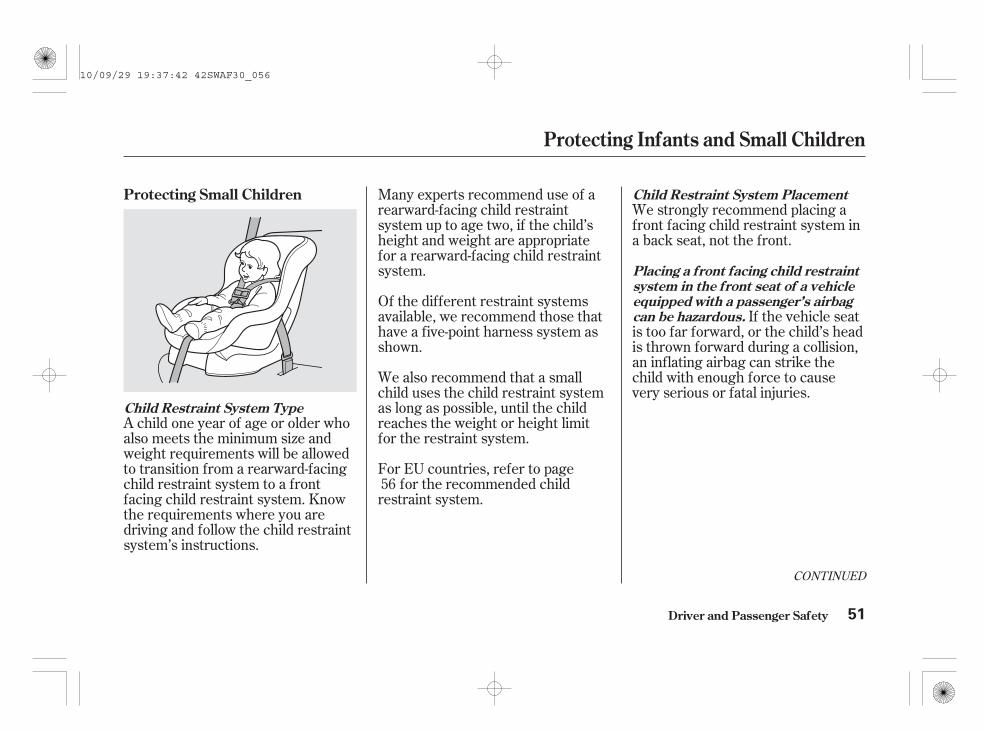
A child one year of age or older whoalso meets the minimum size andweight requirements will be allowedto transition from a rearward-facingchild restraint system to a frontfacing child restraint system. Knowthe requirements where you aredriving and follow the child restraintsystem’s instructions.
We strongly recommend placing afront facing child restraint system ina back seat, not the front.
If the vehicle seatis too far forward, or the child’s headis thrown forward during a collision,an inflating airbag can strike thechild with enough force to causevery serious or fatal injuries.
Many experts recommend use of arearward-facing child restraintsystem up to age two, if the child’sheight and weight are appropriatefor a rearward-facing child restraintsystem.
Of the different restraint systemsavailable, we recommend those thathave a five-point harness system asshown.
We also recommend that a smallchild uses the child restraint systemas long as possible, until the childreaches the weight or height limitfor the restraint system.
For EU countries, refer to pagefor the recommended child
restraint system.56
CONTINUED
Protecting Small Children
Child Restraint System Type
Child Restraint System Placement
Placing a front facing child restraintsystem in the front seat of a vehicleequipped with a passenger’s airbagcan be hazardous.
Protecting Infants and Small Children
Driver and Passenger Safety 51
10/09/29 19:37:42 42SWAF30_056

If it is necessary to put a front facingchild restraint system in the front,move the vehicle seat as far to therear as possible, and be sure thechild restraint system is firmlysecured to the vehicle and the childis properly strapped in the restraintsystem.
Driver and Passenger Safety
Protecting Infants and Small Children
52
Placing a front facing childrestraint system in the frontseat can result in seriousinjury or death if the frontairbag inflates.
If you must place a frontfacing child restraint systemin front, move the vehicleseat as far back as possible,and properly restrain thechild.
10/09/29 19:37:47 42SWAF30_057

In mostcountries, child restraint systemsmust meet the specifications ofthe ECE 44 regulation. Look forthe approval mark on the systemand the manufacturer’s statementof compliance on the box.
Whatever type of child restraint youchoose, to provide proper protection,a child restraint system should meetthree requirements:
The manufacturer of the vehicledoes not assume any responsibilityfor damage which would be causedby a defect inherent in therecommended child restraint system.
When buying a child restraintsystem, you need to choose either aconventional child restraint system,or one designed for use with thelower anchorages and tethers.
We also recommend selecting alower anchorages system-compatiblechild restraint system with a rigid,rather than a flexible, anchor (seepage ).
In EU countries, a child restraintsystem with a flexible anchor is notavailable.
In seating positions and vehicles notequipped with lower anchorages, alower anchorages system-compatiblechild restraint system can beinstalled using a seat belt.
Conventional child restraint systemsmust be secured to a vehicle with aseat belt, whereas lower anchoragessystem-compatible child restraintsystems are secured by attaching therestraint to hardware built into eachrear seating position in the back seat.
Since lower anchorages system-compatible child restraint systemsare easier to install and reduce thepossibility of improper installation,we recommend selecting this style.
59
CONTINUED
The child restraint system shouldmeet safety standards.
1.
Selecting a Child Restraint System
Driver and Passenger Safety 53
10/09/29 19:37:58 42SWAF30_058

Rearward facing for infants, frontfacing for small children.
Make sure the restraint system fitsyour child. Check the manufacturer’sinstructions and labels for height andweight limits.
Before purchasing a conventionalchild restraint system, or using apreviously purchased one, werecommend that you test therestraint system in the specificvehicle seating position or positionswhere the child restraint system willbe used.
For EU countries, refer to pagefor the recommended child
restraint system.56
The child restraint system shouldbe of the proper type and size to fitthe child.
The child restraint system shouldfit the vehicle seating position (orpositions) where it will be used.
3.
2.
Selecting a Child Restraint System
Driver and Passenger Safety54
10/09/29 19:38:06 42SWAF30_059

A child restraint system securedwith a seat belt should be installed asfirmly as possible. However, it doesnot need to be ‘‘rock solid.’’ Someside-to-side movement can beexpected and should not reduce thechild restraint system’s effectiveness.
Afterinstalling a child restraint system,push and pull the restraint systemforward and from side-to-side toverify that it is secure.
If the child restraint system is notsecure, try installing it in a differentseating position, or use a differentstyle of child restraint system thatcan be firmly secured.
After selecting a proper childrestraint system and a good place toinstall the restraint system, there arethree main steps in installing therestraint system:
All childrestraint systems must be securedto the vehicle with the lap part of alap/shoulder belt or with the loweranchorages system. A child whoserestraint system is not properlysecured to the vehicle can beendangered in a crash.
Make sure thechild is properly strapped in thechild restraint system according tothe child restraint system maker’sinstructions. A child who is notproperly secured in a childrestraint system can be seriouslyinjured in a crash.
If you use a lap/shoulder beltwithout an additional lockableretractor, be sure you install alocking clip on the seat belt (seepage ). For EU countries, refer to page
for the recommended childrestraint system.
The following pages provide therecommended child restraintsystems for EU countries andguidelines on how to properly installa child restraint system. A frontfacing child restraint system is usedin all examples, but the instructionsare the same for a rearward facingchild restraint system.
6756
Except for European models
Make sure the child restraintsystem is firmly secured.
Properly secure the child restraintsystem to the vehicle.
Secure the child in the childrestraint system.
1.
3.2.
Installing a Child Restraint System
Driver and Passenger Safety 55
10/09/29 19:38:17 42SWAF30_060

*
*
*
*
*
*
*
*
+
**
Various types of child restraint systems are available. Not all types are suitable for your vehicle. Please refer to thetable below to select which category of child restraint system can be used on each seating position.
The particular child restraints in the above table are Honda Genuine Parts. They are available from your dealer.
A size class is specified for some child restraint systems. Make sure to check the size class as indicated on themanufacturer’s instructions, package, and labels of the child restraint.
Adjust the front seat forward to 30 mm (3 notches) from its rearmost position.Move the front seat to its rearmost position.Seat position not suitable for children in this mass group.Suitable for ‘‘universal’’ category child restraints approved for use in this mass group.
Suitable for particular ISO FIX child restraint systems (CRS) given in this table.Suitable for front facing ISO FIX child restraint systems of universal category approved for use in this massgroup.For group I, the front facing genuine Honda ISO FIX child restraint system is available from your dealer.Suitable for particular child restraint systems given in this table. These restraints may be of the ‘‘specificvehicle,’’ ‘‘restricted,’’ or ‘‘semi-universal’’ category.
U:X:
IL:IUF:
1:2:
L:
Front passenger
XX
Honda LORDHonda KID or Honda KID FIXHonda KID or Honda KID FIX
Rear passengerSeating Position
Mass Group
group 0 Up to 10 kggroup 0 Up to 13 kg
group I 9 kg to 18 kggroup II 15 kg to 25 kggroup III 22 kg to 36 kg
CentreHonda BABY-SAFE
IL (Honda BABY-SAFE ISO FIX) orHonda BABY-SAFE
IUF (Size class A, B1, B) or Honda LOADHonda KID or Honda KID FIXHonda KID or Honda KID FIX
OutboardU
IL (Honda BABY-SAFE ISO FIX)or U
IUF (Size class A, B1, B) or UL (Honda KID FIX) or UL (Honda KID FIX) or U
1
1
1
2
2
2
2
2
Installing a Child Restraint System
Driver and Passenger Safety
For a correct installation, please refer to the Child Restraint Instruction Manual.
Child Restraint System for EU Countries
56
10/09/29 19:38:36 42SWAF30_061
Your vehicle is equipped with loweranchorages at each seating positionon the rear seat. These anchoragesare only to be used with a childrestraint system designed to beattached to the lower anchorages.Refer to page for how to install achild restraint system to the loweranchorages.
Your vehicle has the manualadjustable rear seat. To install a childrestraint system in any seatingposition on the rear seat, slide therear seat as far back as it can go.
58
Installing a Child Restraint System
Driver and Passenger Safety 57
The use of any child restraintsystem which is not suitablefor your vehicles would notproperly secure the infant orchild who could therefore bekilled or seriously injured.
10/09/29 19:38:41 42SWAF30_062

Your vehicle is equipped with loweranchorages at the rear seats tosecure a child restraint system in anyseating position: one in each outerseating position, or one in the centre.
The five lower anchorages arelocated between the seat-back andseat bottom, and are to be used onlywith a child restraint systemdesigned for use with the loweranchorages.
The location of each loweranchorage is indicated by a smallbutton above the anchorage point.
To install a child restraint systemdesigned to be attached to the loweranchorages in either of the rearouter seats:
Store the seat belt buckle ortongue in the storage pockets.For EU countries, refer to page
for the recommended childrestraint system.
When you install a child restraintsystem in the rear centre seating
position, use the centre loweranchorages as shown in theillustration. To install a childrestraint system in either outerseating position, use the outer loweranchorages. You can install up to twochild restraint systems at a timeusing the outer lower anchorages.
Do not attach two child restraintsystem connectors to a single loweranchorage at a time.
1.
56
Installing a Child RestraintSystem with the LowerAnchorages
Installing a Child Restraint System
Driver and Passenger Safety
Using the Outer Lower Anchorages
58
BUTTON
OUTER LOWER ANCHORAGES
LOWER ANCHORAGESfor CENTRE POSITION
LOWERANCHORAGES forOUTER POSITION
10/09/29 19:38:54 42SWAF30_063

Make sure there are no objectsnear the anchorages that couldprevent a secure connectionbetween the child restraint systemand the anchorages.
You may use optional guide-cupsthat came with your child restraintsystem to install it to the loweranchorages without damaging theseat surface.
Attach the guide-cups to thelower anchorages as shown inthe illustration.
When using the guide-cups,always follow the child restraintsystem manufacturer’sinstructions.
Place the child restraint system onthe vehicle seat, then attach thechild restraint system to the loweranchorages according to the childrestraint system maker’sinstructions.
Some child restraint systemsdesigned for use with loweranchorages have a rigid-typeconnector as shown above.
4.
3.
2.
CONTINUED
On some child restraint systems
Installing a Child Restraint System
Driver and Passenger Safety 59
Rigid type
GUIDE-CUP
LOWER ANCHORAGE
10/09/29 19:39:07 42SWAF30_064

Whatever type you have, followthe child restraint system maker’sinstructions for adjusting ortightening the fit.
Flexible type child restraintsystem is available in somecountries. In EU countries, thistype is not available.
Set the head restraint to itshighest position.
Route the tether strap over theseat-back through the outsides ofthe head restraint legs, thenattach the attaching clip to thetether anchor fitting in the ceilingas shown in the illustration. Makesure the strap is not twisted, thentighten the strap according to thechild restraint system maker’sinstructions.
Other child restraints have a flexible-type connector as shown above.
The above illustration shows howthe attaching clip should be routed inEU countries.
5.
7.
6.
Installing a Child Restraint System
Driver and Passenger Safety60
Flexible type ATTACHING CLIP
ANCHOR FITTING
10/09/29 19:39:17 42SWAF30_065

Push and pull the child restraintsystem forward and from side-to-side to verify that it is secure.
To install a child restraint system inthe rear centre seating position, usethe centre lower anchorages asshown above.
Follow step 1 through 5 asdescribed previously to secure thechild restraint system.
On some child restraint types, routethe tether strap between the legs ofthe head restraint as shown.
8.
1.
CONTINUED
Installing a Child Restraint System
Driver and Passenger Safety
Using the Centre Lower Anchorages
61
ATTACHING CLIP
COVERCENTRE LOWERANCHORAGESANCHOR FITTING
ANCHOR FITTING
10/09/29 19:39:27 42SWAF30_066

The design and suitability of thechild restraint systems must becarefully checked with the childrestraint system manufacturerconcerned and the seller of thosesystems. If you are not sure, consultyour dealer before purchasing thistype of child restraint system.
Pull down the cover to access thetether anchor fitting.
Lower the head restraint to itslowest position.
Route the tether strap over theseat-back, then attach theattaching clip to the tether anchorfitting in the centre of the ceiling,making sure the strap is nottwisted. Tighten the strapaccording to the child restraintsystem maker’s instructions.
On some child restraint systems,route the tether strap over thehead restraint as shown.
Push and pull the child restraintsystem forward and from side-to-side to verify that it is secure.
2.
3.
4. 5.
Installing a Child Restraint System
Driver and Passenger Safety62
ATTACHING CLIP
ATTACHING CLIP
ANCHOR FITTING
ANCHOR FITTING
10/09/29 19:39:37 42SWAF30_067
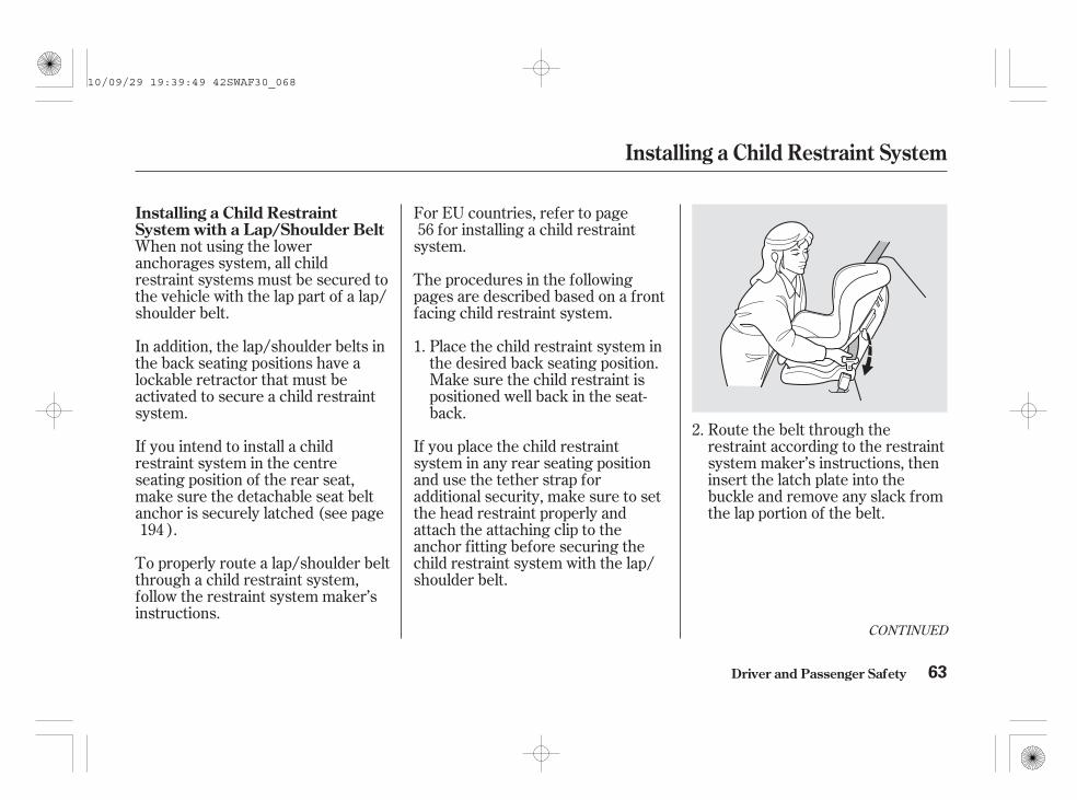
CONTINUED
When not using the loweranchorages system, all childrestraint systems must be secured tothe vehicle with the lap part of a lap/shoulder belt.
Route the belt through therestraint according to the restraintsystem maker’s instructions, theninsert the latch plate into thebuckle and remove any slack fromthe lap portion of the belt.
To properly route a lap/shoulder beltthrough a child restraint system,follow the restraint system maker’sinstructions.
In addition, the lap/shoulder belts inthe back seating positions have alockable retractor that must beactivated to secure a child restraintsystem.
If you intend to install a childrestraint system in the centreseating position of the rear seat,make sure the detachable seat beltanchor is securely latched (see page
).
For EU countries, refer to pagefor installing a child restraint
system.
If you place the child restraintsystem in any rear seating positionand use the tether strap foradditional security, make sure to setthe head restraint properly andattach the attaching clip to theanchor fitting before securing thechild restraint system with the lap/shoulder belt.
Place the child restraint system inthe desired back seating position.Make sure the child restraint ispositioned well back in the seat-back.
The procedures in the followingpages are described based on a frontfacing child restraint system.
2.
1.
56
194
Installing a Child Restraint System
Driver and Passenger Safety
Installing a Child RestraintSystem with a Lap/Shoulder Belt
63
10/09/29 19:39:49 42SWAF30_068

To activate the lockable retractor,slowly pull the shoulder part of thebelt all the way out until it stops.
Push down the tab. Route theshoulder part of the belt into theslit at the side of the restraint,then let the belt feed back into theretractor.
After the belt has retracted, tugon it. If the belt is locked, youwill not be able to pull it out. Ifyou can pull the belt out, it is notlocked, and you will need torepeat these steps.
After confirming that the belt islocked, grab the shoulder part ofthe belt near the buckle, and pullup to remove any slack from thelap part of the belt. Remember, ifthe lap part of the belt is not tight,the child restraint system will notbe secure.
4.3.
5.
6.
Installing a Child Restraint System
Driver and Passenger Safety64
TAB
10/09/29 19:39:59 42SWAF30_069
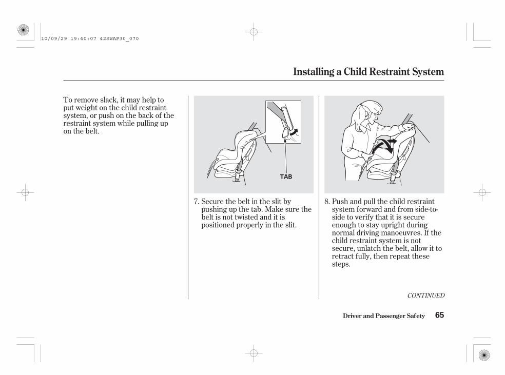
To remove slack, it may help toput weight on the child restraintsystem, or push on the back of therestraint system while pulling upon the belt.
Push and pull the child restraintsystem forward and from side-to-side to verify that it is secureenough to stay upright duringnormal driving manoeuvres. If thechild restraint system is notsecure, unlatch the belt, allow it toretract fully, then repeat thesesteps.
Secure the belt in the slit bypushing up the tab. Make sure thebelt is not twisted and it ispositioned properly in the slit.
8.7.
CONTINUED
Driver and Passenger Safety
Installing a Child Restraint System
65
TAB
10/09/29 19:40:07 42SWAF30_070

To deactivate the lockable retractorand remove a child restraint system,unlatch the buckle, unroute the seatbelt, and let the belt fully retract.
When you secure a child restraintsystem with a lap/shoulder belt, besure you install a locking clip on theseat belt (see page ).67
On vehicles without lockable retractorfitted to the seat where the child ispositioned
Installing a Child Restraint System
Driver and Passenger Safety
Except for European models
66
LOCKING CLIP
10/09/29 19:40:14 42SWAF30_071

To install a locking clip, do thefollowing:
Place the child restraint in the seatwith a lap/shoulder belt. Route thelap/shoulder belt through therestraint according to the seatmanufacturer’s instructions.
Insert the latch plate into thebuckle. Pull on the shoulder partof the belt to make sure there isno slack in the lap portion.
Tightly grasp the belt near thelatch plate. Pinch both parts of thebelt together so they won’t slipthrough the latch plate. Unbucklethe seat belt.
Install the locking clip as shown.Position the clip as close aspossible to the latch plate.
If it is necessary to put a front facingchild restraint system in the front,move the vehicle seat as far to therear as possible, be sure the childrestraint system is firmly secured tothe vehicle, and the child is properlystrapped in the restraint system (seepage ).
A locking clip is usually includedwith the child restraint system. Ifyou need a clip, contact the seat’smanufacturer or a store that sellschild restraints.
Always use a seat belt locking clipwhen you secure a child restraintsystem to your vehicle with a lap/shoulder belt. This helps prevent therestraint system from shiftingposition or overturning.
Insert the latch plate into thebuckle. Push and pull on the childrestraint system to verify that it isheld firmly in place. If it is not,repeat these steps until therestraint is secure.
1.
2.
3.4.
5.
51
On vehicles without lockable retractorfitted to the seat where the child ispositioned
Installing a Child Restraint System
Driver and Passenger Safety
Using a Seat Belt Locking ClipExcept for European models
67
LOCKING CLIP
10/09/29 19:40:27 42SWAF30_072

Children riding in vehicles should berestrained to minimize the risk ofinjury in the event of an accident.
Since a tether can provide additionalsecurity to the lap/shoulder beltinstallation, we recommend using atether whenever one is required oravailable. (The owners may checkwith the child restraint systemmaker to determine whether a tetheris available for a particular childrestraint system.)
A child restraint system with a tethercan be installed in any seatingposition in the back seat, using oneof the anchor points shown in theillustration.
The above illustration shows howthe tether strap should be routedin EU countries.
Set the head restraint to itshighest position.
After properly securing the childrestraint system (see page or
), route the tether strap overthe seat-back and on both sides ofthe head restraint as shown.
1.
2.58
63
Installing a Child RestraintSystem with a Tether
Installing a Child Restraint System
Driver and Passenger Safety
Using an Outer Anchor Fitting
68
ANCHOR FITTINGTETHER STRAP
ATTACHING CLIP
TETHER ANCHOR POINTS
10/09/29 19:40:40 42SWAF30_073

Attach the attaching clip to theanchor fitting, making sure thestrap is not twisted.
Tighten the tether strap accordingto the child restraint systemmaker’s instructions.
Push down the rear centre headrestraint to the lowest position.
After properly securing the childrestraint system (see page ),open the anchor cover.
On some child restraint types, routethe tether strap between the legs ofthe head restraint as shown.
1.
2.63
3.
4.
CONTINUED
Installing a Child Restraint System
Driver and Passenger Safety
Using the Centre Anchor
69
ATTACHING CLIP
ANCHOR FITTING COVER
ANCHOR FITTING
10/09/29 19:40:51 42SWAF30_074

To attach the tether to the childrestraint system, follow the childrestraint system maker’s instructions.
When the child restraint system isused, follow the instructions thatcame with the child restraint system.
Tighten the tether strap accordingto the child restraint systemmaker’s instructions.
On some child restraint systems,route the tether strap over the headrestraint as shown.
Route the tether strap on bothsides of the head restraint, thenattach the attaching clip to thetether anchor fitting, making surethe tether strap is not twisted.
3.
4.
Child restraint anchoragesare designed to withstand only thoseloads imposed by correctly fitted childrestraints. Under no circumstances arethey to be used for adult seat belts,harnesses or for attaching other itemsor equipment to the vehicle.
Driver and Passenger Safety
Installing a Child Restraint System
70
WARNING:
ATTACHING CLIP ATTACHING CLIP
ANCHOR FITTINGANCHOR FITTING
10/09/29 19:41:01 42SWAF30_075

When a child reaches therecommended weight or height limitfor a front facing child restraintsystem, the child should sit in a backseat on a booster seat and wear thelap/shoulder belt.
The following pages giveinstructions on how to check properseat belt fit, what kind of boosterseat to use if one is needed, andimportant precautions for a childwho must sit in front.
Protecting Larger Children
Driver and Passenger Safety 71
Leaning over the front doorcan result in serious injury ordeath if the side airbaginflates.
Always sit upright with theirback against the seat-back.
Make sure the seat-backs arelatched securely beforedriving.
Allowing a child age 12 orunder to sit in front can resultin injury or death if thepassenger’s front airbaginflates.
If a child must ride in front,move the vehicle seat as farback as possible, use abooster seat if needed, havethe child sit up properly andwear the seat belt properly.
10/09/29 19:41:08 42SWAF30_076

To determine if a lap/shoulder beltproperly fits a child, have the childput on the seat belt, then askyourself:
Does the child sit all the way backagainst the seat?
Do the child’s knees bendcomfortably over the edge of theseat?
Does the shoulder belt crossbetween the child’s neck and arm?
Is the lap part of the belt as low aspossible, touching the child’sthighs?
Will the child be able to stayseated like this for the whole trip?
If you answer yes to all thesequestions, the child is ready to wearthe lap/shoulder belt correctly. Ifyou answer no to any question, thechild needs to ride on a booster seat. A child who has outgrown a front
facing child restraint system shouldride in a back seat and use a boosterseat until the lap/shoulder belt fitsthem properly without the booster.
1.
2.
3.
4.
5.
Using a Booster SeatChecking Seat Belt Fit
Protecting Larger Children
Driver and Passenger Safety72
10/09/29 19:41:21 42SWAF30_077

A child may continue using a boosterseat until the tops of their ears areeven with the top of the vehicle’s orbooster’s seat-back. A child of thisheight should be tall enough to usethe lap/shoulder belt without abooster seat.
Booster seats can be high-back orlow-back. Whichever style you select,make sure the booster seat meetsapproved safety standards (see page
) and that you follow the boosterseat maker’s instructions.
If a child who uses a booster seatmust ride in front, move the vehicleseat as far back as possible and besure the child is wearing the seatbelt properly.
A back-rest may be available for aspecific booster seat. Install theback-rest to the booster seat andadjust it to the vehicle seat accordingto the booster seat maker’sinstructions. Make sure the seat beltis properly routed through the guideat the shoulder of the back-rest andthe belt does not touch and cross thechild’s neck (see page ).
For EU countries, refer to pagefor the booster seat placement.56
21
53
Protecting Larger Children
Driver and Passenger Safety 73
GUIDE
10/09/29 19:41:30 42SWAF30_078

The back seat is the safest place fora child of any age or size.
If the passenger’s front airbaginflates in a moderate to severefrontal collision, the airbag can causeserious injuries to a child who isunrestrained, improperly restrained,sitting too close to the airbag, or outof position.
Of course, children vary widely. Andwhile age may be one indicator ofwhen a child can safely ride in front,there are other important factors youshould consider.
To safely ride in front, a child mustbe able to follow the rules, includingsitting properly, and wearing the seatbelt properly throughout a ride.
If you decide that a child can safelyride up front, be sure to:
Carefully read the owner’s manual,and make sure you understand allseat belt instructions and all safetyinformation.
Move the vehicle seat to the rear-most position.
Have the child sit up straight, backagainst the seat, and feet on ornear the floor.
Check that the child’s seat belt isproperly and securely positioned.
It is recommended that all childrenage 12 and under be properlyrestrained in the back seat.
Physically, a child must be largeenough for the lap/shoulder belt toproperly fit (see pages and ). Ifthe seat belt does not fit properly,with or without the child sitting on abooster seat, the child should not sitin front.
Remind the child not to leantoward the door.
A side airbag also poses risks. If anypart of a larger child’s body is in thepath of a deploying side airbag, thechild could receive possibly seriousinjuries. Supervise the child. Even a mature
child sometimes needs to bereminded to fasten the seat belt orsit properly.
21 72
When Can a Larger Child Sit inFront
Physical Size
Maturity
Protecting Larger Children
Driver and Passenger Safety74
10/09/29 19:41:47 42SWAF30_079

This could resultin serious neck injuries during acrash.
This couldcause very serious injuries duringa crash. It also increases thechance that the child will slideunder the belt in a crash and beinjured.
If they do, theycould be very seriously injured in acrash.
Devices intended toimprove a child’s comfort orreposition the shoulder part of aseat belt can make the belt lesseffective and increase the chanceof serious injury in a crash.
Additional Safety PrecautionsDo not let a child wear a seat beltacross the neck.
Do not let a child put the shoulderpart of a seat belt behind the backor under the arm.
Two children should never use thesame seat belt.
Do not put any accessories on aseat belt.
Protecting Larger Children
Driver and Passenger Safety 75
10/09/29 19:41:55 42SWAF30_080

Your vehicle’s exhaust containscarbon monoxide gas. Carbonmonoxide should not enter thevehicle in normal driving if youmaintain your vehicle properly andfollow the information on this page.
Have the exhaust system inspectedfor leaks whenever:
High levels of carbon monoxide cancollect rapidly in enclosed areas,such as a garage. Do not run theengine with the garage door closed.Even with the door open, run theengine only long enough to move thevehicle out of the garage.
Select the fresh air mode.Select the mode.Turn the fan on high speed.Set the temperature control to acomfortable setting.
With the tailgate open, airflow canpull exhaust gas into your vehicle’sinterior and create a hazardouscondition. If you must drive with thetailgate open, open all the windows,and set the heating and coolingsystem/climate control system asshown below.
If you must sit in your parked vehiclewith the engine running, even in anunconfined area, adjust the heatingand cooling system/climate controlsystem as follows:
The vehicle is raised for an oilchange.You notice a change in the soundof the exhaust.The vehicle was in a collision thatmay have damaged the underside. 1.
2.3.4.
Carbon Monoxide Hazard
Driver and Passenger Safety76
Carbon monoxide gas is toxic.Breathing it can causeunconsciousness and evenkill you.
Avoid any enclosed areas oractivities that expose you tocarbon monoxide.
10/09/29 19:42:06 42SWAF30_081

**
*
*
These labels are in the locationsshown. They warn you of potentialhazards that could cause seriousinjury. Read these labels carefully.
If a label comes off or becomes hardto read, contact your dealer for areplacement.
CONTINUED
Safety Labels
Driver and Passenger Safety 77
SIDE AIRBAG
EXPANSION TANK CAP DANGER LABEL
(Diesel models)
CHILD SAFETY/SRS AIRBAG
(Left-hand drive type)
CHILD SAFETY/SRS AIRBAG
(Right-hand drive type)
RADIATOR CAP DANGER LABEL
BATTERY DANGER LABEL(Petrol models)
If equipped1 :2 : Passenger’s side only
CHILD SAFETY
DUAL DECK LUGGAGE SHELF WARNING
2
1
10/09/29 19:42:14 42SWAF30_082

The label shown below is attached toeach front doorjamb. Symbols on top of the
engine under the engine cover are toremind you to follow the servicemanual instructions. When replacingthe injectors, your authorized dealershould perform this work. Contactyour dealer.
The label shown below is attached tothe left side on the dual deckluggage shelf.
On vehicles with dual deck luggageshelf
On Diesel models
Safety Labels
Driver and Passenger Safety78
Side Airbag
Safety alert symbol
Safety alert symbol
Follow owner’ s manualinstructions carefullyFollow owner’s manual
instructions carefully
10/09/29 19:42:27 42SWAF30_083

This section gives information aboutthe controls and displays thatcontribute to the daily operation ofyour vehicle. All the essentialcontrols are within easy reach.
...........................Control Locations . 80............................Instrument Panel . 82
..........Instrument Panel Indicators . 86.............................................Gauges . 99
.............................Speedometer . 100...............................Tachometer . 100
.................Temperature Gauge . 100................................Fuel Gauge . 100
............Multi-information Display . 101Controls Near the Steering
.........................................Wheel . 142Windscreen Wipers and
.....................................Washers . 144.......Turn Signals and Headlights . 148
..........Front and Rear Fog Lights . 150Adaptive Front Lighting System
..........................................(AFS) . 153
......Instrument Panel Brightness . 155...............Hazard Warning Button . 156...............Rear Window Demister . 156
.......................Headlight Adjuster . 158......Steering Wheel Adjustments . 159
.............................Keys and Locks . 160......................Immobilizer System . 162
..............................Ignition Switch . 163....................................Door Locks . 164
....................Power Door Locks . 164...........................Super Locking . 167
Auto Door Locking/..............................Unlocking . 168
............Childproof Door Locks . 173.....................Remote Transmitter . 174
..........................................Tailgate . 179...............................................Seats . 181
Driver’s Seat Power..........................Adjustments . 181
........Manual Seat Adjustments . 182Driver’s Seat Height
............................Adjustment . 183....................................Armrests . 184
.............Luggage Pass-through . 184........................Head Restraints . 185
........Reclining the Front Seats . 189
.Folding the Rear Seats Down . 190Folding the Rear Seat
.................................Forward . 192...................Detachable Anchor . 194
..................................Seat Heaters . 196..............................Tonneau Cover . 197
...........Dual Deck Luggage Shelf . 200............................Power Windows . 203
...........................................Sunroof . 205......................................Sunshades . 207
...........................................Mirrors . 209...............................Parking Brake . 212
.........Interior Convenience Items . 213......................Lower Glove Box . 214......................Upper Glove Box . 214.....................Beverage Holders . 215
........Accessory Power Sockets . 216.............Console Compartment . 217
....................Sunglasses Holder . 217................Conversation Mirror . 218
..................................Coat Hook . 218...................................Sun Visor . 219
............................Vanity Mirror . 219......................Cigarette Lighter . 219
.......................................Ashtray . 220...............................Interior Lights . 221
Instruments and Controls
Instruments and Controls 79
10/09/29 19:42:33 42SWAF30_084

*
* *
**
*
*
* *
*
*
If equipped:
Control Locations
Instruments and Controls80
Left-hand drive type
Vehicle without navigation system is shown.
SEAT HEATERSWITCHES
HAZARD WARNINGBUTTON
AUXILIARYINPUT JACK
CLIMATE CONTROLSYSTEM
MIRROR CONTROLS
POWER DOOR LOCKMASTER SWITCH
POWER WINDOWSWITCHES
FUEL FILL DOORRELEASE HANDLE
CLOCK
AUDIO SYSTEM
USB ADAPTERCABLE
DOOR LOCKS
HEATING/COOLINGCONTROLS
BONNET RELEASE HANDLE
ACCESSORYPOWER SOCKET
(P.210)
(P.164)
(P.164)
(P.203)
(P.196) (P.290) (P.216)
(P.274, 282)
(P.243)
(P.156)(P.233)
(P.226) SUNSHADE SWITCHSUNROOF SWITCH (P.205)
(P.207)
(P.354)
(P.356)
MANUALTRANSMISSION
AUTOMATICTRANSMISSION
(P.101)
MULTI-INFORMATIONDISPLAY
(P.293)
(P.376)
(P.381)
10/09/29 19:42:42 42SWAF30_085

*
*
*
*
*
*
*
*
**
* If equipped:
Control Locations
Instruments and Controls 81
Right-hand drive type
Vehicle without navigation system is shown.
MULTI-INFORMATION DISPLAY
MIRROR CONTROLS
POWER DOOR LOCKMASTER SWITCH
POWER WINDOWSWITCHES
BONNET RELEASEHANDLE
FUEL FILL DOORRELEASE HANDLE
DOOR LOCKS
HEATING/COOLINGCONTROLS
CLIMATE CONTROLSYSTEM
SUNSHADE SWITCHSUNROOF SWITCH
(P.243)
(P.226)
(P.233)
(P.203)
(P.164)
(P.164)
(P.210)
(P.101)(P.207)(P.205)
HAZARD WARNINGBUTTON(P.156)
CLOCK
USB ADAPTER CABLE(P.274, 282)
AUDIO SYSTEM
(P.293)
MANUAL TRANSMISSION(P.376)AUTOMATIC TRANSMISSION(P.381)
SEAT HEATER SWITCHES(P.196)
ACCESSORY POWERSOCKET(P.216)
AUXILIARY INPUT JACK(P.290)
(P.356)
(P.354)
10/09/29 19:42:51 42SWAF30_086

*
*
Since the indicators vary between models, some indicators are not on your vehicle.On vehicle with adaptive cruise control (ACC), indicator (Amber, Green) is located in this position(P. ).
:94
Instrument Panel (Petrol models)
Instruments and Controls
Automatic Transmission
82
FRONT FOG LIGHTINDICATOR
LIGHTS ON INDICATOR
MALFUNCTIONINDICATOR LAMP
VEHICLE STABILITYASSIST (VSA) SYSTEMINDICATOR
ELECTRIC POWERSTEERING (EPS)INDICATOR
ADAPTIVE FRONT LIGHTINGSYSTEM (AFS) INDICATOR
HIGH BEAM INDICATOR
LOW FUEL INDICATOR
ANTI-LOCK BRAKESYSTEM INDICATOR
SEAT BELT REMINDERINDICATOR
CRUISE CONTROLMAIN INDICATOR
IMMOBILIZER SYSTEM INDICATOR
CHARGING SYSTEM INDICATORSECURITY SYSTEM INDICATOR
VSA ACTIVATION INDICATOR
SUPPLEMENTALRESTRAINT SYSTEMINDICATOR
LOW OIL PRESSUREINDICATOR
DEFLATION WARNINGSYSTEM INDICATOR
SYSTEM MESSAGE INDICATOR
PARKING BRAKE AND BRAKE SYSTEM INDICATOR
REAR FOG LIGHT INDICATOR
(P.94)
(P.96)
(P.97)
(P.97)
(P.91)
(P.90)
(P.91)
(P.39, 89)
(P.86)
(P.89)
(P.93)
(P.89)
(P.93)
(P.93)
COLLISION MITIGATIONBRAKING SYSTEM(CMBS) INDICATOR
CRUISE CONTROL INDICATOR
(P.92)
(P.95)
(P.92)
(P.96)
(P.92)
(P.86, 548)
(P.87, 544)
(P.87, 547)
(P.88, 551)
10/09/29 19:43:02 42SWAF30_087

*
*
Since the indicators vary between models, some indicators are not on your vehicle.On vehicle with adaptive cruise control (ACC), indicator (Amber, Green) is located in this position(P. ).
:94
Instrument Panel (Petrol models)
Instruments and Controls
Manual Transmission
83
ANTI-LOCK BRAKESYSTEM INDICATOR
LOW FUEL INDICATOR
VEHICLE STABILITYASSIST (VSA) SYSTEMINDICATOR
SEAT BELT REMINDERINDICATOR
SUPPLEMENTALRESTRAINTSYSTEM INDICATOR
ELECTRIC POWERSTEERING (EPS)INDICATOR
VSA ACTIVATIONINDICATOR
SYSTEM MESSAGE INDICATOR
SHIFT DOWN INDICATORDEFLATION WARNINGSYSTEM INDICATOR
IMMOBILIZER SYSTEM INDICATOR
CRUISE CONTROL MAIN INDICATOR
SHIFT UP INDICATOR
FRONT FOG LIGHTINDICATOR
MALFUNCTION INDICATORLAMP
LIGHTS ON INDICATOR
REAR FOG LIGHT INDICATOR
HIGH BEAM INDICATOR
LOW OIL PRESSURE INDICATOR
CHARGING SYSTEM INDICATOR
PARKING BRAKE AND BRAKESYSTEM INDICATOR SECURITY SYSTEM INDICATOR
(P.92)
(P.96)
(P.92)
(P.89)
(P.98)
(P.96)
(P.95)
(P.91)
(P.97)
(P.98)
(P.97)
(P.90)
(P.91)
(P.39, 89)
(P.86)
(P.93)
(P.92)
(P.89)
(P.93)CRUISE CONTROLINDICATOR
COLLISION MITIGATIONBRAKING SYSTEM (CMBS)INDICATOR
(P.93)
ADAPTIVE FRONT LIGHTINGSYSTEM (AFS) INDICATOR(P.94)
(P.86, 548)
(P.87, 544)
(P.87, 547)
(P.88, 551)
10/09/29 19:43:15 42SWAF30_088

*
*
Since the indicators vary between models, some indicators are not on your vehicle.On vehicle with adaptive cruise control (ACC), indicator (Amber, Green) is located in this position(P. ).
:94
Instrument Panel (Diesel models)
Instruments and Controls
Automatic Transmission
84
IMMOBILIZER SYSTEM INDICATOR
PARKING BRAKE AND BRAKE SYSTEM INDICATOR
REAR FOG LIGHT INDICATOR
LIGHTS ON INDICATOR
MALFUNCTION INDICATOR LAMP
ADAPTIVE FRONT LIGHTINGSYSTEM (AFS) INDICATOR
FRONT FOG LIGHTINDICATOR
LOW FUEL INDICATOR
CHARGING SYSTEMINDICATOR
ANTI-LOCK BRAKESYSTEM INDICATOR
VEHICLE STABILITY ASSIST(VSA) SYSTEM INDICATOR
SEAT BELT REMINDERINDICATOR
SUPPLEMENTALRESTRAINT SYSTEMINDICATOR
HIGH BEAM INDICATOR
VSA ACTIVATION INDICATOR SYSTEM MESSAGE INDICATOR
DEFLATION WARNING SYSTEM INDICATORSECURITY SYSTEMINDICATOR
LOW OIL PRESSURE INDICATOR
GLOW PLUGS INDICATOR
CRUISE CONTROL MAIN INDICATOR(P.92)
(P.96)
(P.94)
(P.92)
(P.96)
(P.97)
(P.95)
(P.88)
(P.97)
(P.91)
(P.90)
(P.39, 89)
(P.86)
(P.92)
(P.89)
(P.93)
(P.89)(P.93)
(P.93)CRUISE CONTROL INDICATOR
COLLISION MITIGATIONBRAKING SYSTEM (CMBS)INDICATOR
(P.86, 549)
(P.87, 547)
(P.87, 544)
(P.88, 551)
10/09/29 19:43:27 42SWAF30_089

*
*
Since the indicators vary between models, some indicators are not on your vehicle.On vehicle with adaptive cruise control (ACC), indicator (Amber, Green) is located in this position(P. ).
:94
Instruments and Controls
Instrument Panel (Diesel models)Manual Transmission
85
LOW FUEL INDICATORDEFLATION WARNINGSYSTEM INDICATOR
IMMOBILIZER SYSTEM INDICATOR
PARKING BRAKE AND BRAKESYSTEM INDICATOR
CHARGING SYSTEM INDICATOR
HIGH BEAM INDICATOR
SHIFT UP INDICATOR
REAR FOG LIGHTINDICATOR
LOW OIL PRESSUREINDICATOR
GLOW PLUGS INDICATOR
SHIFT DOWN INDICATOR
SECURITY SYSTEM INDICATOR
SUPPLEMENTALRESTRAINTSYSTEM INDICATOR
SEAT BELT REMINDERINDICATOR
VSA ACTIVATIONINDICATOR
VEHICLE STABILITYASSIST (VSA) SYSTEMINDICATOR
ANTI-LOCK BRAKESYSTEM INDICATOR
CRUISE CONTROL MAIN INDICATOR
SYSTEM MESSAGE INDICATOR
(P.92)
(P.96)
(P.98)
(P.95)
(P.88) (P.91)
(P.97)
(P.98)
(P.97)
(P.90)
(P.86)
(P.93)
(P.92)
(P.89)
(P.93)
(P.89)
(P.92)
ADAPTIVE FRONT LIGHTINGSYSTEM (AFS) INDICATOR
LIGHTS ON INDICATOR
FRONT FOG LIGHT INDICATOR
MALFUNCTION INDICATOR LAMP
(P.94)
(P.96)
CRUISE CONTROL INDICATOR
COLLISION MITIGATIONBRAKING SYSTEM (CMBS)INDICATOR
(P.93)
(P.39, 89)
(P.86, 549)
(P.87, 544)
(P.87, 547)
(P.88, 551)
10/09/29 19:43:38 42SWAF30_090

The instrument panel has manyindicators to give you importantinformation about your vehicle. This indicator comes on when you
turn the ignition switch to the ON(II) position. It reminds you and yourpassengers to fasten your seat belts.A beeper also sounds if you have notfastened your seat belt.
If you turn the ignition switch to theON (II) position before fasteningyour seat belt, the beeper soundsand the indicator flashes. If you donot fasten your seat belt before thebeeper stops, the indicator stopsflashing but remains on.
If a front passenger does not fastentheir seat belt, the indicator willcome on about 6 seconds after theignition switch is turned to the ON(II) position.
See page on petrol models andpage on diesel models.
This indicator will also come onwhen you restart the engine afteryour vehicle has run out of fuel (seepage ).
If either the driver or a frontpassenger does not fasten their seatbelt while driving, the beeper willsound and the indicator will flashagain at regular intervals. For moreinformation, see page .
You will also see the symbol ‘‘ ’’(for a driver)/‘‘ ’’ (for a frontpassenger), or this symbol with a‘‘FASTEN YOUR SEAT BELT’’ or‘‘FASTEN YOUR PASSENGER’SSEAT BELT’’ message on the multi-information display to remind youand your passengers to fasten yourseat belts.
You will also see the symbol ‘‘ ,’’or this symbol with a ‘‘CHECKSYSTEM’’ message on the multi-information display.
26548
549
501
Malfunction IndicatorLamp
Seat Belt ReminderIndicator
On Diesel models only
Instrument Panel Indicators
Instruments and Controls86
10/09/29 19:43:53 42SWAF30_091
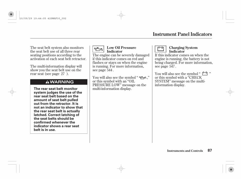
The engine can be severely damagedif this indicator comes on red andflashes or stays on when the engineis running. For more information,see page .
The multi-information display willshow you the seat belt use on therear seat (see page ).
The seat belt system also monitorsthe seat belt use of all three rearseating positions according to theactivation of each seat belt retractor.
If this indicator comes on when theengine is running, the battery is notbeing charged. For more information,see page .
You will also see the symbol ‘‘ ,’’or this symbol with an ‘‘OILPRESSURE LOW’’ message on themulti-information display.
You will also see the symbol ‘‘ ’’or this symbol with a ‘‘CHECKSYSTEM’’ message on the multi-information display.
27544
547
Charging SystemIndicator
Low Oil PressureIndicator
Instrument Panel Indicators
Instruments and Controls 87
The rear seat belt monitorsystem judges the use of therear seat belt based on theamount of seat belt pulledout from the retractor. It isnot an indicator to show thatthe rear seat belt is actuallylatched. Correct latching ofthe seat belts should beconfirmed whenever theindicator shows a rear seatbelt is in use.
10/09/29 19:44:05 42SWAF30_092

If it remains lit after you fullyrelease the parking brake whilethe engine is running, or if itcomes on while driving, therecould be a problem with the brakesystem. For more information, seepage .
This indicator has two functions:
It comes on when you turn theignition switch to the ON (II)position. It is a reminder to checkthe parking brake. A beepersounds if you drive with theparking brake not fully released.Driving with the parking brake notfully released can damage thebrakes and tyres.
You will also see the symbol‘‘ ,’’ or this symbol with a‘‘RELEASE PARKING BRAKE’’message in the multi-informationdisplay (see page ).
You will also see the symbol‘‘ ,’’ or this symbol with a‘‘CHECK SYSTEM’’ message onthe multi-information display (seepage ).
This indicator comes on for a fewseconds (several seconds in coldweather or at high altitudes) whenyou turn the ignition switch to theON (II) position. When the engine iscold, wait for the indicator to go offbefore starting the engine.
If you experience any of thefollowing symptoms, there may be aproblem with the water temperaturesensor of the fuel system. Have yourvehicle inspected by your dealer.
It is hard to start the engine.
This indicator goes out faster thannormal when the outsidetemperature is very low.
1.
2.
212
551
551
Instrument Panel Indicators
Instruments and Controls
Parking Brake andBrake System Indicator
Glow Plugs Indicator(Diesel models only)
88
10/09/29 19:44:20 42SWAF30_093

This indicator comes on briefly whenyou turn the ignition switch to theON (II) position. If it comes on atany other time, it indicates apotential problem with your frontairbags. This indicator will also alertyou to a potential problem with yourside airbags, side curtain airbags, orautomatic seat belt tensioners. Formore information, see page .
This indicator normally comes on fora few seconds when you turn theignition switch to the ON (II)position, and when the ignitionswitch is turned to the START (III)position. If it comes on at any othertime, there is a problem with theABS. If this happens, have yourvehicle checked at a dealer. Withthis indicator on, your vehicle stillhas normal braking ability but noanti-lock function. For moreinformation, see page .
You will also see the symbol ‘‘ ,’’or this symbol with a ‘‘CHECKSYSTEM’’ message on the multi-information display (see page ).
This indicator comes on when thereis a system message on the multi-information display. Press the INFObutton on the steering wheel to seethe message (see page ).
You will also see the symbol ‘‘ ,’’or this symbol with a ‘‘CHECKSYSTEM’’ message on the multi-information display.
This indicator will also alert you tothe seat belt e-pretensioners.
Most of the time, this indicatorcomes on along with other indicatorsin the instrument panel such as theseat belt reminder indicator,supplemental restraint systemindicator, VSA system indicator, etc.
102
39
389
389On vehicles with collision mitigationbraking system (CMBS)
Instrument Panel Indicators
Instruments and Controls
Supplemental RestraintSystem Indicator
System MessageIndicator
Anti-lock Brake System(ABS) Indicator
89
10/09/29 19:44:34 42SWAF30_094

This indicator normally comes on fora few seconds when you turn theignition switch to the ON (II)position.
This indicator has two functions:
You will also see the symbol‘‘ ’’ or this symbol with a‘‘CHECK TYRE PRESSURE’’message on the multi-informationdisplay.
If this happens, pull to the side ofthe road when it is safe, checkwhich tyre has lost pressure, anddetermine the cause. If it isbecause of a flat tyre, replace theflat tyre with the compact spare (ifequipped) (see page ) or usethe tyre repair kit (if equipped)(see page ). Then have the flattyre repaired as soon as possible.If two or more tyres areunderinflated, call a professionaltowing service (see page ).This indicator may come onunexpectedly due to the conditionof your tyres or road surfaces. Formore information, see page .
If this indicator begins to flash,there is a problem with thedeflation warning system. You willalso see the symbol ‘‘ ’’ or thissymbol with a ‘‘CHECK SYSTEM’’message on the multi-informationdisplay. The indicator continues toflash for a while (approximately 1minute), then stays on. If thishappens, have your dealer checkthe system as soon as possible.For more information, see page
.
If it comes on while driving [over25 km/h (15 mph)], it indicatesthat one of your vehicle’s tyresmay be low on pressure.
1.
2.
512
519
562
404
404
Deflation WarningSystem Indicator
Instrument Panel Indicators
Instruments and Controls90
10/09/29 19:44:46 42SWAF30_095

This indicator comes on briefly whenyou turn the ignition switch to theON (II) position. It will go off if youhave inserted a properly codedignition key. If it is not a properlycoded key, the indicator will blinkand the engine’s fuel system will bedisabled (see page ).
If you turn the steering wheel to thefull left or right position repeatedlywhile stopping or driving at very lowspeed, you may feel slightly hardersteering in order to prevent damageto the steering system caused byoverheating. This may also happen ifyou hold the steering wheel on thefull left or right position for a while.
This indicator normally comes onwhen you turn the ignition switch tothe ON (II) position and goes offafter the engine starts. If it comes onat any other time, there is a problemin the electric power steering system.
If this happens, stop the vehicle in asafe place and turn off the engine.Reset the system by restarting theengine. The indicator will stay on,but should go off after driving ashort distance. If it does not go off,or comes back on again while driving,take the vehicle to your dealer tohave it checked. With the indicatoron, the EPS may be turned off,making the vehicle harder to steer.
You will also see the symbol ‘‘ ’’or this symbol with a ‘‘CHECKSYSTEM’’ message on the multi-information display.
162
Immobilizer SystemIndicator
Electric Power Steering(EPS) Indicator(For some types)
Instrument Panel Indicators
Instruments and Controls 91
10/09/29 19:44:59 42SWAF30_096

This indicator comes on when youturn on the rear fog light. See page
for information on operating therear fog light.
This indicator comes on when youturn on the front fog lights. See page
for information on operating thefront fog lights.
This indicator normally comes on fora few seconds when you turn theignition switch to the ON (II)position, and when the ignitionswitch is turned to the START (III)position.
If it comes on and stays on at anyother time, there is a problem withthe VSA system. Take your vehicleto a dealer to have it checked.Without VSA, your vehicle still hasnormal driving ability, but will nothave VSA traction and stabilityenhancement. See page for moreinformation on the VSA system.
This indicator may also come on ifthere is a problem with the trailerstability assist function (see page
).
You will also see the symbol ‘‘ ,’’or this symbol with a ‘‘CHECKSYSTEM’’ message on the multi-information display (see page ).
150
151
402
419
402
Rear Fog Light Indicator
Front Fog LightIndicator(For some types)
Vehicle Stability Assist(VSA) System Indicator
Instrument Panel Indicators
Instruments and Controls92
10/09/29 19:45:13 42SWAF30_097

This indicator has four functions:
It comes on as a reminder that youhave turned off the vehiclestability assist (VSA) system.
It flashes when VSA is active (seepage ).
It flashes when trailer stabilityassist is activating (see page ).
It comes on along with the VSAsystem indicator if there is aproblem with the VSA system.You will also see the symbol‘‘ ,’’ or this symbol with a‘‘CHECK SYSTEM’’ message onthe multi-information display (seepage ).
This indicator normally comes on fora few seconds when you turn theignition switch to the ON (II)position, and when the ignitionswitch is turned to the START (III)position. For more information, seepage .
This indicator comes on when youset the cruise control. See page
for information on operating thecruise control.
This indicator comes on when youturn on the cruise control system bypressing the CRUISE button on thesteering wheel (see page ).
1.
2.
3.
4.
402
419
402
402
298
298
If equipped
If equipped
VSA Activation Indicator Cruise Main Indicator
Cruise Control Indicator
Instrument Panel Indicators
Instruments and Controls 93
10/09/29 19:45:30 42SWAF30_098

If the indicator comes on amber,there is a problem with the ACCsystem. You will also see the symbol‘‘ ’’ or this symbol with a‘‘CHECK SYSTEM’’ message on themulti-information display. Take yourvehicle to your dealer to have itchecked. For more information, seepage .
When you push the ACC button onthe steering wheel, this indicatorcomes on green. You will also see‘‘ACC’’ on the multi-informationdisplay (see page ).
It comes on as a reminder that youhave turned off the adaptive frontlighting system (AFS) by pressingthe AFS off switch (see page ).
This indicator blinks when there is aproblem with the AFS system.
You will also see the symbol ‘‘ ’’or this symbol with a ‘‘CHECKSYSTEM’’ message on the multi-information display.
This indicator normally comes on fora few seconds when you turn theignition switch to the ON (II)position.
This indicator normally comes on fora few seconds when you turn theignition switch to the ON (II)position.
154
301
308
If equipped
If equipped
Adaptive Cruise Control(ACC) Indicator (Green)
Adaptive Front LightingSystem (AFS) Indicator(For some types)
Adaptive Cruise Control(ACC) Indicator (Amber)
Instrument Panel Indicators
Instruments and Controls94
ACC INDICATOR
10/09/29 19:45:46 42SWAF30_099

If this happens, stop the vehicle in asafe place, turn the ignition switch tothe ACCESSORY (I) or LOCK (0)position, and restart the engine. Ifthe indicator blinks again, take yourvehicle to a dealer to have it checked.For more information, see page .
This indicator normally comes on fora few seconds when you turn theignition switch to the ON (II)position. It also comes on as areminder that you have turned offthe collision mitigation brakingsystem (CMBS) by pressing theCMBS off switch (see page ).
The CMBS indicator also comes onif dirt or other debris blocks theradar sensor in the front grille.When you clean the radar sensor,the indicator should go off the nexttime you turn the ignition switch tothe ON (II) position.
If the indicator comes on at anyother time, there is a problem withthe CMBS. You will also see thesymbol ‘‘ ’’ or this symbol with a‘‘CHECK SYSTEM’’ message on themulti-information display. If thishappens, take your vehicle to adealer, and have it checked. Formore information, see page .When this indicator is on, the CMBSis not working.
153
396
397
On vehicle with the adaptive cruisecontrol system
Collision MitigationBraking System (CMBS)Indicator
Instrument Panel Indicators
Instruments and Controls 95
10/09/29 19:45:56 42SWAF30_100

You will also see the symbol‘‘ ,’’ or this symbol with a‘‘HEADLIGHTS ON’’ message onthe multi-information display (seepage ).
This indicator also comes on whenthe light switch is in AUTO and thelights turn on automatically.
This indicator comes on with thehigh beam headlights. For moreinformation, see page .
This indicator reminds you that theexterior lights are on. It comes onwhen the light switch is in either the
or position. If you turn theignition switch to the ACCESSORY(I) or the LOCK (0) position withoutturning off the light switch, thisindicator will remain on. A reminderchime will also sound when you openthe driver’s door and remove the keyfrom the ignition switch.
When you press the hazard warningbutton, both turn signal indicatorsand all turn signals on the outside ofthe vehicle will flash.
Your vehicle has the one-push turnsignal feature to signal a lane changeeasily (see page ).
The left or right turn signal indicatorblinks when you signal a lane changeor turn. If an indicator does not blinkor blinks rapidly, it usually meansone of the turn signal bulbs isburned out (see pages and ).Replace the bulb as soon as possible,since other drivers cannot see thatyou are signaling.
148
149 148
469 471
On vehicles with automatic lighting onfeature
Instruments and Controls
Instrument Panel Indicators
High Beam Indicator
Lights On Indicator
Turn Signal and Hazard WarningIndicators
96
10/09/29 19:46:09 42SWAF30_101

You will also see the symbol‘‘ ,’’ or this symbol with a‘‘FUEL LOW’’ (petrol models) or‘‘DIESEL FUEL LOW’’ (dieselmodels) message on the multi-information display.
Refer toon page if your vehicle runs outof fuel.
This indicator comes on as areminder that you must refuel soon.
When the indicator comes on, thereare about 8.6 (2.3 US gal, 1.89 Impgal) of fuel remaining in the tank.
This indicator comes on when thesecurity system is set. See page
for more information on thesecurity system.
When the indicator comes on, thereare about 8.1 (2.14 US gal, 1.78 Impgal) of fuel remaining in the tank.
When the reading reaches 0 (E),there is a very small amount of fuelin the tank.295
501
On petrol models
On diesel models
On diesel modelsPriming the Fuel System
Low Fuel IndicatorSecurity System Indicator(For some types)
Instrument Panel Indicators
Instruments and Controls 97
SECURITY SYSTEM INDICATOR
10/09/29 19:46:23 42SWAF30_102

Either the shift up or shift downindication comes on to show you theappropriate time to change a higheror lower gear. For more information,see pages , , and .298 305 379
On vehicles with manual transmissionexcept South Africa model
Instrument Panel Indicators
Instruments and Controls
Shift Up/Shift Down Indicators
98
SHIFT UP INDICATOR
SHIFT DOWN INDICATOR
10/09/29 19:46:31 42SWAF30_103

Gauges
Instruments and Controls 99
SPEEDOMETER
MULTI-INFORMATION DISPLAY
TACHOMETER
SELECT/RESET KNOBTEMPERATURE GAUGEFUEL GAUGE
M/T diesel model with navigation system is shown.
10/09/29 19:46:37 42SWAF30_104

This shows the temperature of theengine’s coolant. During normaloperation, the reading should be inthe middle of the gauge. In severedriving conditions, such as very hotweather or a long period of uphilldriving, the reading may reach nearthe red mark. If it reaches the red(hot) mark, pull safely to the side ofthe road. Turn to page on petrolmodels and page on dieselmodels for instructions andprecautions on checking the enginecooling system.
This shows how much fuel you have.It may show slightly more or lessthan the actual amount.
Avoid driving with an extremely lowfuel level. Running out of fuel couldcause the engine to misfire,damaging the catalytic converter.
The malfunction indicator lamp orthe PGM-FI indicator will come onwhen you restart the engine afteryour vehicle has run out of fuel.
This shows your speed in kilometersper hour (km/h).
This shows your speed in miles perhour (mph). The inside scales showthe speed in kilometers per hour(km/h).
You can set the vehicle speed alarm.For more information, see page .
The tachometer shows the enginespeed in revolutions per minute(rpm). To protect the engine fromdamage, never drive with thetachometer needle in the red zone.
116
540542
On petrol models only
On diesel models only
On vehicles with kilometer indication
On vehicles with mile indication
Fuel GaugeTemperature GaugeSpeedometer
Tachometer
Gauges
Instruments and Controls100
10/09/29 19:46:49 42SWAF30_105

The multi-information displayconsists of an upper segment, amiddle segment and a lowersegment. Each segment can displaytwo lines of messages.
In normal display mode, the upperand middle segments display the tripcomputer and the rear seat belt use,and the lower segment displays theodometer, trip meter, and outsidetemperature.
The multi-information displaybetween the speedometer andtachometer on the instrument paneldisplays various information andsymbols/messages when the ignitionswitch is in the ON (II) position.Some of the indicators/messageshelp you operate your vehicle moreeffectively. Others keep you awareof the vehicle’s condition forcontinued trouble-free driving.
There are two types of symbols/messages: normal display symbols/messages and system warningsymbols/messages.
You can select the displayedlanguage and also customize somevehicle control settings to your likingwith the multi-information displayand the two buttons on the steeringwheel (see page ).102
CONTINUED
Normal Display Symbols/Messages
Multi-Information Display
Instruments and Controls 101
UPPER SEGMENT UPPER SEGMENT
LOWER SEGMENTLOWER SEGMENT
MIDDLE SEGMENT MIDDLE SEGMENT
Kilometer indication type Mile indication type
10/09/29 19:47:01 42SWAF30_106

If there is any system warning,system warning symbol(s) will beshown on the multi-informationdisplay following the speed alarmsetting. The system warningsymbol/message that has thehighest priority will be displayed firstwhen you turn the ignition switch tothe ON (II) position.
The trip computer consists of theinstant fuel economy, the averagefuel economy, the estimated distance,the elapsed time, and the averagespeed. The upper segment alwaysdisplays one of the trip computeritems as a primary display, and themiddle segment shows your lastselection when you turn the ignitionswitch to the ON (II) position. Youcan customize it to your preference
(see page ).
In the middle segment, the rear seatbelt use is also displayed.
In the default setting, the upperdisplay shows the instant fueleconomy when you turn the ignitionswitch to the ON (II) position. Theremaining trip computer items aredisplayed in the middle segment.
Each time you press the INFObutton ( ), the trip computerchanges from the average fueleconomy to the estimated distance tothe elapsed time to the averagespeed and then to the rear seat beltuse as shown on the next page.
132
Multi-Information Display
Instruments and Controls102
SEL/RESETBUTTON
INFOBUTTON
SEL/RESETBUTTON
INFOBUTTON
On vehicles with adaptive cruisecontrol (ACC)
On vehicles without adaptive cruisecontrol (ACC)
10/09/29 19:47:09 42SWAF30_107
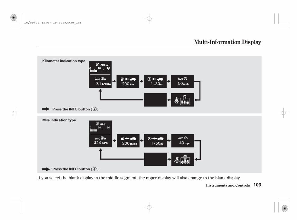
If you select the blank display in the middle segment, the upper display will also change to the blank display.
Multi-Information Display
Instruments and Controls 103
Mile indication type
Kilometer indication type
: Press the INFO button ( ).
: Press the INFO button ( ).
10/09/29 19:47:19 42SWAF30_108

: Your vehicle’s instant fueleconomy is shown in l/100 km.
Indicators in the trip computer show:
: The time travelled sinceyou last turned the ignition switch tothe ON (II) position.
This distance is estimated from thefuel economy you have achievedover the last few kilometers (miles),so it will vary with changes in speed,traffic condition, etc.
: The estimated distance youcan travel on the fuel remaining inthe tank.
: Your vehicle’s instant fueleconomy is shown in mpg.
The display may show an instant fueleconomy reading higher than innormal driving while the particulatematter (PM) is burnt and removedfrom the diesel particulate filter(DPF). For more information, seepage .
: The average speed you aretravelling is displayed in kilometersper hour (km/h) or miles per hour(mph) depending on the model.
: Your vehicle’s average fueleconomy since you last reset the tripcomputer A.
: Your vehicle’s average fueleconomy since you last reset the tripcomputer B.
The average fuel economy isupdated once every 10 seconds.When you reset a trip meter, theaverage fuel economy for that tripmeter also resets. To reset thevalues in the trip computer, pressand hold the SEL/RESET buttonuntil the number resets to ‘‘0.0.’’
In the customizing mode, you can setTrip A and average fuel economy Ato reset when you refuel your vehicle(see page ).
577
134
Kilometer indication type
Mile indication type
Diesel models
Trip Computer Range
Elapsed Time
Instant Fuel Economy
Average Vehicle Speed
Average Fuel Economy
Multi-Information Display
Instruments and Controls104
10/09/29 19:47:41 42SWAF30_109

The odometer shows the totalnumber of kilometers or miles yourvehicle has been driven.
This meter shows the number ofkilometers or miles driven since youlast reset it.
There are two trip meters: trip A andtrip B. To switch the display betweenthem, press the SEL/RESET buttonrepeatedly. When you turn theignition switch to the ON (II)position, your last selection isdisplayed.
Each trip meter works independently,so you can keep track of twodifferent distances.
To reset a trip meter, display it, andthen press and hold the SEL/RESETbutton until the number resets to‘‘0.0.’’
The lower segment always showsthe odometer, trip meter and theoutside temperature in the normaldisplay mode.
‘‘ ’’ or ‘‘ ’’ will bedisplayed when the average fueleconomy is selected in the uppersegment, depending on which tripmeter (trip A or trip B) is displayedin the lower segment.
CONTINUED
Odometer
Trip Meter
Multi-Information Display
Instruments and Controls 105
OUTSIDE TEMPERATUREINDICATOR
TRIP METER
ODOMETER
Kilometer indication type is shown.
10/09/29 19:47:53 42SWAF30_110

±This indicator displays the outsidetemperature in degrees Celsius.
The temperature sensor is in thefront bumper. Therefore, thetemperature reading can be affectedby heat reflection from the roadsurface, engine heat, and theexhaust from surrounding traffic.This can cause an incorrecttemperature reading when yourspeed is under 30 km/h (19 mph).
The sensor delays the display updateuntil it reaches the correct outsidetemperature. This may take severalminutes.
If the outside temperature isincorrectly displayed, you can adjustit by up to 3°C warmer or cooler(see page ).
The temperature must bestabilized before doing thisprocedure.
In certain weather conditions,temperature readings near freezingcould mean that ice is forming on theroad surface. You will also see acaution symbol ‘‘ ’’ on the multi-information display.
130
Outside Temperature Indicator
Multi-Information Display
Instruments and Controls106
NOTE:
10/09/29 19:48:04 42SWAF30_111

If there is a problem with yourvehicle, for example, the engine oillevel is low or a door is not fullyclosed, the multi-information displaywill show you the problem. It doesthis by interrupting the currentdisplay with one or more symbols/messages. Most of the symbols/messages are displayed for about 5seconds, and then the currentdisplay returns. Some symbols/messages stay on until the problemis corrected.
Usually, the symbols/messages areshown in the upper and middlesegments. If the adaptive cruisecontrol (ACC) or the collisionmitigation braking system (CMBS)is selected, only the symbols aredisplayed in the middle segment andthe ACC or CMBS information isdisplayed in the upper segment.
When your vehicle is new, the multi-information display shows thesystem warning symbols without themessages. This is the default settingwhen the vehicle leaves the factory.You can customize this setting to seethe system warning symbols withmessages (see page ). Somesymbols such as the low outsidetemperature, rear seat belt reminderindicator, etc., do not come with amessage.
In this section, system symbolswithout messages are used in almostall examples.The multi-information display will
also show you some vehicleconditions such as the adaptivecruise control (ACC) settings, thecollision mitigation braking system(CMBS), the speed alarm settings,etc.
129
CONTINUED
System Warning Symbols
Multi-Information Display
Instruments and Controls 107
10/09/29 19:48:13 42SWAF30_112
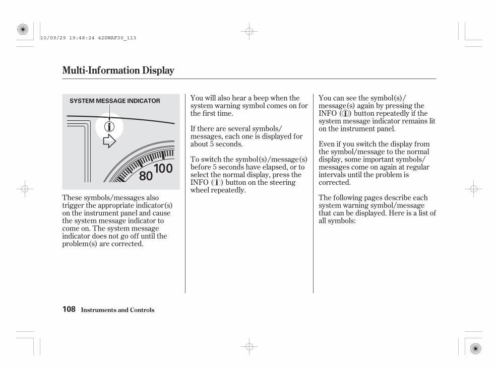
Even if you switch the display fromthe symbol/message to the normaldisplay, some important symbols/messages come on again at regularintervals until the problem iscorrected.
You will also hear a beep when thesystem warning symbol comes on forthe first time.
If there are several symbols/messages, each one is displayed forabout 5 seconds.
The following pages describe eachsystem warning symbol/messagethat can be displayed. Here is a list ofall symbols:
These symbols/messages alsotrigger the appropriate indicator(s)on the instrument panel and causethe system message indicator tocome on. The system messageindicator does not go off until theproblem(s) are corrected.
To switch the symbol(s)/message(s)before 5 seconds have elapsed, or toselect the normal display, press theINFO ( ) button on the steeringwheel repeatedly.
You can see the symbol(s)/message(s) again by pressing theINFO ( ) button repeatedly if thesystem message indicator remains liton the instrument panel.
Multi-Information Display
Instruments and Controls108
SYSTEM MESSAGE INDICATOR
10/09/29 19:48:24 42SWAF30_113

CONTINUED
See page39.
See page91.
See page212.
See page548.
See page549.
See page544.
See page545.
See page546.
See page551.
See page547.
See page550.
See page389.
See page454.
See page381.
See page402.
Petrol models
Diesel models
Multi-Information Display
Instruments and Controls 109
10/09/29 19:48:39 42SWAF30_114

See page17.
See page153.
See page26.
See page26.
See page27.
See pages90 and 404.
See pages90 and 405.
See pages302, 317 and
394.
See pages396 and 397.
See page393.
See page319.
See page578.
See page579.
See pages307 and 317.
See pages307 and 317.
Multi-Information Display
Instruments and Controls110
10/09/29 19:48:53 42SWAF30_115

See page106.
See page163.
See page96.
See page149.
See page116.
See page116.
See page97.
See page97.
See page420.
See page462.
Petrol models
Diesel models
Multi-Information Display
Instruments and Controls 111
10/09/29 19:49:03 42SWAF30_116

*
*
*
*
*
*
*
*
*
*
**
*
You can customize some of the vehicle control settings to suit your needs. The table shows the settings you cancustomize.
Your last selection is the default setting.Factory default settingSetting is available while driving.1 :
3 :2 :
4 : On vehicles with adaptive cruise control (ACC)
ACCSETUP
PRE-RUNNING CARDETECT BEEPACC DISPLAY SPEEDUNIT
SPEED ALARM 1 (ON/OFF, Setting)SPEED ALARM 2 (ON/OFF, Setting)
SPEED ALARM 1 (ON/OFF)SPEED ALARM 2 (ON/OFF)
Sets the speed alarm on and changes the alarmspeed setting.
Sets the speed alarm on.
Initialises the deflation warning system.
Sets the beep to sound when the system detects avehicle ahead of you.Changes the displayed measurement with theACC on.
ON/OFFover 5 km/h (mph) with5 km/h (mph) stepsON/OFF
CANCELOK
ON /OFF
km/hmph
116
119
407
125
126
SPEED ALARM(P.116)
DEFLATIONWARNINGSYSTEMINITIALISATION(P.407)CHG SETTING(P.122) 4
1
1
2
2
2
2
3
3
Menu Item Description Setting Option PageGroup Setup
Customized Settings
Multi-Information Display
Instruments and Controls112
10/09/29 19:49:16 42SWAF30_117

*
*
*
*
*
*
±
*
CONTINUED
Group Setup Menu Item Description Setting Option PageMETERSETUP
WARNING MESSAGEADJUST OUTSIDETEMP. DISPLAYPRIMARY DISPSELECTION
TRIP A RESET WITHREFUELELAPSED TIME RESET
CHG SETTING(P.122)
LANGUAGE(P.138)
DEFAULT ALL(P.139)
Switches warning message to be displayed or not.Changes the outside temperature reading aboveor below its current reading.Changes the primary displayed trip computer itemin the upper segment.
Causes trip meter A and the average fuel economyA to reset when you refuel.Selects the setting to reset the elapsed time ofyour current trip.Changes the language used in the display.
Returns all settings to the factory default.
ON/OFFup to 3°C0°CInstant fuel economy ,Average fuel economy,Elapsed time, Range,Average speedON/OFF
IGN OFF , TRIP A,TRIP BENGLISH , ITALIAN,SPANISH, GERMAN,FRENCH, PORTUGUESECANCELOK
129130
132
134
135
138
139
Factory default setting:
Multi-Information Display
Instruments and Controls 113
10/09/29 19:49:26 42SWAF30_118

To enter the customizing mode, thevehicle must be stopped with theignition switch in the ON (II)position and the parking brake set onvehicles with manual transmission. Ifyour vehicle has the automatictransmission, the shift lever shouldbe in Park. (Exceptionally, thiscondition is not applied on somespeed alarm settings.) Press andhold the INFO button ( ) on thesteering wheel for about 3 secondswhile the multi-information display isin its normal display. Here are thesettings you can customize.
SPEED ALARM: To set the speedalarm (see page ).
DEFLATION WARNINGSYSTEM INITIALISATION: Toinitialise the deflation warningsystem (see pages and ).
CHG SETTING: To changevehicle control settings (see page
).Each time you press the INFObutton, the display changes as shownabove.
DEFAULT ALL: To return to thedefault settings (see page ).
LANGUAGE: To select language(see page ).
116
121
122
138
139
407
Instruments and Controls
Multi-Information Display
114
: Press the INFO button ( ).
10/09/30 16:40:30 42SWAF30_119

You can also select the specifiedspeed alarm while driving. If you setthe alarm to the specified vehiclespeed while driving, select ‘‘SPEEDALARM,’’ and refer to page .
If you do not select any settings onthe display after you press the INFObutton and the setting menu isdisplayed, the customizing modedisplay will return to the normaldisplay after about 10 seconds.
If you try to start driving whilecustomizing the settings, you will seethe above display for a few secondsand customizing will be cancelled.
If you want to change any vehiclecontrol settings, select ‘‘CHGSETTING,’’ and follow theinstructions on page .
If you want the settings as they werewhen the vehicle left the factory,select ‘‘DEFAULT ALL,’’ asdescribed on page .
Use the INFO button ( ) on thesteering wheel to see and scrollthrough the settings, and the SEL/RESET button to enter yourselections.
Customizing is also cancelled, if youturn the ignition switch out of theON (II) position to the ACCESSORY(I) or LOCK (0) position, or releasethe parking brake (M/T) or movethe shift lever out of Park (A/T).
If you select and press theSEL/RESET button, the normaldisplay is shown again.122
139
119
Multi-Information Display
Instruments and Controls 115
10/09/29 19:49:51 42SWAF30_120

You can access different alarmfunctions when the vehicle isstopped or while driving. Whiledriving, you can select either of thetwo speed alarm settings. When yourvehicle is stopped, you can customizethe setting speed to your preference.
Press and hold the INFO button toenter the customizing mode, thenpress and release the INFO buttonrepeatedly to select ‘‘SPEEDALARM.’’ While the multi-information display is showing‘‘SPEED ALARM,’’ press the SEL/RESET button. The display changesto the setting mode.
If you set the speed alarm function inthe custom settings, you will see thisindicator and hear a beep when thevehicle speed reaches the set speed.You can set two different speeds forthe alarm.
To set the speed alarm while the vehicleis stopped:
Speed Alarm
Multi-Information Display
Instruments and Controls116
Alarm at vehicle speed 80 km/h
10/09/29 19:50:00 42SWAF30_121

CONTINUED
Select either of the setting modes (1or 2), then select on or off bypressing the SEL/RESET buttonrepeatedly.
Speed setting 1: You can set thealarm on or off, and adjust thesetting speeds above or below50 km/h (30 mph).
Speed setting 2: You can set thealarm on or off, and adjust thesetting speeds above or below80 km/h (50 mph).
Each time you press and release theINFO button ( ), the selected iconis changed between set 1, 50 km/h(30 mph), and set 2, 80 km/h (50mph). Then press the INFO buttonagain to exit ( ).You can set the speed alarm in km/h
or mph, depending on models. Thetwo speed selections and the on/offsetting icons are displayed.
Multi-Information Display
Instruments and Controls 117
Alarm onAlarm off
Press the SEL/RESET button.km/h type is shown.
Speed setting 1 off is selected.
10/09/29 19:50:12 42SWAF30_122

+-
Once you have made your selection,press and release the INFO button tomove to the exit mode. Press theSEL/RESET button to enter yoursetting. If you press the INFO button,the display goes back to the settingmode. Repeat the setup.
Each time you press the SEL/RESET button, the setting speedincreases or decreases by 5 km/h(mph). You can set the speed valuesover 5 km/h (5 mph) with 5 km/h(mph) steps. Always follow theposted speed limit and never drivefaster than is safe for the trafficconditions.
To enter your selection, select theSET icon by pressing the INFObutton, then press the SEL/RESETbutton.
The displayed number is the currentspeed setting. Select either the or
icon by pressing the INFO buttonrepeatedly, then press the SEL/RESET button to change the settingvalue.
To adjust the setting speed, selecteither of the setting speeds, thenpress and release the SEL/RESETbutton. The display changes to thespeed setting screen.
Multi-Information Display
Instruments and Controls118
10/09/29 19:50:21 42SWAF30_123

To select the alarm speed while driving:
To exit the customizing mode, selectthe exit mode shown above bypressing the INFO button repeatedly,then press the SEL/RESET button.The display goes back to the normaldisplay.
Press the INFO button for about 1second to switch the display. You willsee the speed alarm settings on themulti-information display.
You can select the alarm speedbetween the two setting speeds:50 km/h and 80 km/h, or 30 mphand 50 mph, depending on models.Each time you press and release theINFO button, the selected icon ischanged between the setting speedsand the exit icon.
CONTINUED
Multi-Information Display
Instruments and Controls 119
km/h type is shown.
10/09/29 19:50:30 42SWAF30_124

After pressing the SEL/RESETbutton, the display shows yoursetting for a few seconds, then goesback to the normal display.
If you do not press any button, thedisplay returns to the normal displayafter about 10 seconds.
After your selection, press andrelease the INFO button to move tothe exit mode. Press the SEL/RESET button to enter your setting.If you press the INFO button, thedisplay goes back to the settingmode. Repeat the setup.
Select the desired setting speed,then press the SEL/RESET button.Each time you press the SEL/RESET button, the selected speedicon switches between on and off.
Multi-Information Display
Instruments and Controls120
Alarm on
Alarm off Alarm on
10/09/29 19:50:39 42SWAF30_125

After replacing a flat tyre with aspecified regular tyre, or repairing aflat tyre, you should initialise thedeflation warning system to reset it.The system should also be initialisedafter the air pressures on yourvehicle’s tyres are checked. Formore information, see page .
Your vehicle has the deflationwarning system. If the systemdetects a possibility of a significantlylow tyre pressure, the deflationwarning system indicator on theinstrument panel comes on and stayson. The multi-information display willalso show you the symbol ‘‘ ,’’ orthis symbol with a ‘‘CHECK TYREPRESSURE’’ message.
407
Deflation Warning SystemInitialisation
Multi-Information Display
Instruments and Controls 121
10/09/29 19:50:46 42SWAF30_126

*
*
You can customize some of thevehicle control settings to yourpreference. On vehicles withadaptive cruise control (ACC)system, the change setting consistsof the two main items; ACC Setupand Meter Setup, and each mainitem has some custom settings. Onthe other vehicles, the changesetting consists of all items in themeter setup menu. The followingitems are the settings you cancustomize.
Change Setting
Multi-Information Display
Instruments and Controls122
: ACC Setup is available on vehicles with adaptive cruise control.
: Press the SEL/RESET button.
: Press the INFO button.
Go to the ACCSetup CustomizeSetting Display(See page 124).
Go to the MeterSetup CustomizeSetting Display(See page 128).
10/09/29 19:50:53 42SWAF30_127

Press and hold the INFO button toenter the customizing mode, thenpress and release the INFO buttonrepeatedly to select ‘‘CHG SETTING.’’While the multi-information displayis showing ‘‘CHG SETTING,’’ pressthe SEL/RESET button. The displaychanges to the setting mode.
Press and release the INFO buttonrepeatedly until you see the setupyou want to customize, and press theSEL/RESET button to enter yourselection. Each time you press theINFO button, the display changes asshown. To customize each setting,follow the procedures described onthe following pages.
To exit, select the exit mode shownabove by pressing the INFO buttonrepeatedly, then press the SEL/RESET button. The display willreturn to the ‘‘CHG SETTING’’display.
To return to the normal display from‘‘CHG SETTING,’’ select the
display, then press the SEL/RESET button.
CONTINUED
Multi-Information Display
Instruments and Controls 123
10/09/29 19:51:01 42SWAF30_128

ACC DISPLAY SPEED UNIT:Measurements in the ACC displaycan be selected; km or miles (seepage ).
PRE-RUNNING CAR DETECTBEEP: You can turn on or off thealarm when the system detects avehicle ahead of you (see page
).
You can customize either of theadaptive cruise control (ACC)system settings to your preference.Here are the settings you cancustomize.
125
126
On vehicles with adaptive cruise control(ACC)
Adaptive Cruise Control (ACC) Setup
ACC Setup
Multi-Information Display
Instruments and Controls124
: Press the SEL/RESET button.
: Press the INFO button.
10/09/29 19:51:09 42SWAF30_129

You can select ‘‘ON’’ or ‘‘OFF’’. Eachtime you press the INFO button, theselected mode switches between onand off. Enter your selection bypressing the SEL/RESET button.
When your selection is successfullycompleted, the display shows‘‘SETUP ON’’ for a few seconds,then goes back to the ‘‘CHGSETTING’’ display. Press the SEL/RESET button, then press the INFObutton repeatedly to select anothercustomizing mode.
With this setting on, a beep soundswhen the system detects a vehicleahead of you. You will also hear abeep when the vehicle goes out ofthe range of your vehicle’s radarsensor. While the multi-informationdisplay is showing ‘‘PRE-RUNNINGCAR DETECT BEEP,’’ press theSEL/RESET button. The displaychanges to the setting display.
CONTINUED
Pre-Running Car Detect Beep
Multi-Information Display
Instruments and Controls 125
10/09/29 19:51:20 42SWAF30_130

If you fail to enter your selection,you will see ‘‘INCOMPLETE’’ on thedisplay for a few seconds. Thedisplay returns to the setting mode.Repeat the setup.
To exit the customizing mode, selectthe exit mode by pressing the INFObutton repeatedly, then press theSEL/RESET button. The displaygoes back to the ‘‘PRE-RUNNINGCAR DETECT BEEP’’ display.
To return to the normal display,select the display, then pressthe SEL/RESET button.
The speed unit measurements of theadaptive cruise control can beselected; km/h or mph.
While the multi-information displayis showing ‘‘ACC DISPLAY SPEEDUNIT,’’ press the SEL/RESETbutton. The display changes to thesetting display.
Adaptive Cruise Control (ACC)Display Speed Unit
Multi-Information Display
Instruments and Controls126
10/09/29 19:51:31 42SWAF30_131

You can select ‘‘km/h’’ or ‘‘mph’’.The highlighted item is the currentsetting. Each time you press theINFO button, the selected itemchanges. Enter your selection bypressing the SEL/RESET button.
When your selection is successfullycompleted, the display shows‘‘SETUP km/h’’ for a few seconds,then goes back to the ‘‘CHGSETTING’’ display. Press the SEL/RESET button, then press the INFObutton repeatedly to select anothercustomizing mode.
If you fail to enter your selection,you will see ‘‘INCOMPLETE’’ on thedisplay for a few seconds. Thedisplay returns to the setting mode.Repeat the setup.
To exit this mode without changingthe current setting, select ,and press the SEL/RESET button.
CONTINUED
Multi-Information Display
Instruments and Controls 127
10/09/29 19:51:40 42SWAF30_132

+ -
WARNING MESSAGE: Thewarning message is displayed withthe symbol or not (see page ).
You can customize some of thevehicle control settings to suit yourneeds. The following items are thesettings you can customize.
ADJUST OUTSIDE TEMP.DISPLAY: The outsidetemperature indicator value isadjustable up to or 3°C (seepage ).
PRIMARY DISP SELECTION: Atrip computer item displayed inthe upper segment can be selected(see page ).
TRIP A RESET WITH REFUEL:Average fuel economy for tripmeter A can be reset afterrefueling (see page ).
ELAPSED TIME RESET: Theelapsed time can be reset whenyou turn the ignition switch to theLOCK (0) position or when youreset trip meter A or B (see page
).
129
130
132
134135
Meter Setup
Multi-Information Display
Instruments and Controls128
: Press the INFO button.
: Press the SEL/RESET button.
10/09/29 19:51:51 42SWAF30_133

You can see message(s) with thesystem warning symbol on the multi-information display. While the multi-information display is showing‘‘WARNING MESSAGE,’’ press theSEL/RESET button. The displaychanges to the setting display.
When your selection is successfullycompleted, the display shows‘‘SETUP ON’’ for a few seconds,then goes back to the ‘‘CHGSETTING’’ display. Press the SEL/RESET button, then press the INFObutton repeatedly to select anothercustomizing mode.
You can select ‘‘ON’’ or ‘‘OFF’’. Eachtime you press the INFO button, theselected mode switches between on,off, and exit ( ). Enter yourselection by pressing the SEL/RESET button.
CONTINUED
Warning Message
Multi-Information Display
Instruments and Controls 129
10/09/29 19:52:01 42SWAF30_134
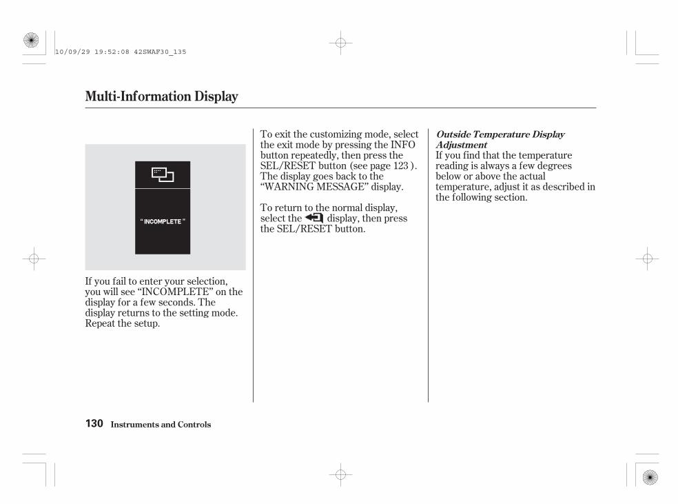
If you fail to enter your selection,you will see ‘‘INCOMPLETE’’ on thedisplay for a few seconds. Thedisplay returns to the setting mode.Repeat the setup.
To exit the customizing mode, selectthe exit mode by pressing the INFObutton repeatedly, then press theSEL/RESET button (see page ).The display goes back to the‘‘WARNING MESSAGE’’ display.
To return to the normal display,select the display, then pressthe SEL/RESET button.
If you find that the temperaturereading is always a few degreesbelow or above the actualtemperature, adjust it as described inthe following section.
123
Outside Temperature DisplayAdjustment
Multi-Information Display
Instruments and Controls130
10/09/29 19:52:08 42SWAF30_135

+ -
+ + +- - -
±
While the multi-information displayis showing ‘‘ADJUST OUTSIDETEMP. DISPLAY,’’ press the SEL/RESET button. The display changesto the setting display.
The highlighted number is thecurrent adjustment above or belowthe outside temperature. Selecteither or icon by pressing theINFO button repeatedly then pressthe SEL/RESET button to changethe setting value. You can select thevalue between 0, 1, 2, 3, and 0,
1, 2, 3. To enter your selection,select the SET icon by pressing theINFO button, then press the SEL/RESET button.
When your selection is successfullycompleted, the display shows‘‘SETUP 0°C’’ for a few seconds,then goes back to the ‘‘CHGSETTING’’ display. Press the SEL/RESET button, then press the INFObutton repeatedly to select anothercustomizing mode.
CONTINUED
Multi-Information Display
Instruments and Controls 131
CURRENT ADJUSTMENT
10/09/29 19:52:18 42SWAF30_136

If you fail to enter your selection,you will see ‘‘INCOMPLETE’’ on thedisplay for a few seconds. Thedisplay returns to the setting mode.Repeat the setup.
To exit the customizing mode, selectthe exit mode by pressing the INFObutton repeatedly, then press theSEL/RESET button. The displaygoes back to the normal display.
Here are the settings you cancustomize:
: Instant fuel economy
: Estimated distance
: Average fuel economy
: Time travelled since youlast turned the ignition switch to theON (II) position
: Average speed
You can select a trip computer itemdisplayed in the upper segment. Thetrip computer consists of the instantfuel economy, the average fueleconomy, the estimated distance, theelapsed time, and the average speed.The upper segment always displaysone of the trip computer items as aprimary display when you turn theignition switch to the ON (II)position. This selected item in theupper segment does not switch evenif you press the INFO button. Formore information of each tripcomputer items, see page .104
Primary Display Selection
Multi-Information Display
Instruments and Controls132
10/09/29 19:52:32 42SWAF30_137
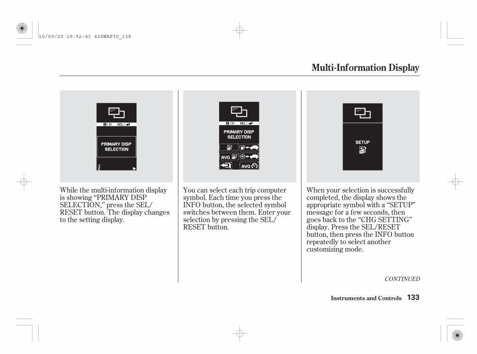
While the multi-information displayis showing ‘‘PRIMARY DISPSELECTION,’’ press the SEL/RESET button. The display changesto the setting display.
You can select each trip computersymbol. Each time you press theINFO button, the selected symbolswitches between them. Enter yourselection by pressing the SEL/RESET button.
When your selection is successfullycompleted, the display shows theappropriate symbol with a ‘‘SETUP’’message for a few seconds, thengoes back to the ‘‘CHG SETTING’’display. Press the SEL/RESETbutton, then press the INFO buttonrepeatedly to select anothercustomizing mode.
CONTINUED
Multi-Information Display
Instruments and Controls 133
10/09/29 19:52:41 42SWAF30_138

To cause the trip meter A and theaverage fuel economy for trip A toreset every time you refuel yourvehicle, adjust it as follows.
If you fail to enter your selection,you will see ‘‘INCOMPLETE’’ on thedisplay for a few seconds. Thedisplay returns to the setting mode.Repeat the setup.
If you select and press theSEL/RESET button, the normaldisplay is shown again.
You can select ‘‘ON’’ or ‘‘OFF’’. Eachtime you press the INFO button, theselected mode switches between on,off, and exit ( ). Enter yourselection by pressing the SEL/RESET button.While the multi-information display
is showing ‘‘TRIP A RESET WITHREFUEL,’’ press the SEL/RESETbutton. The display changes to thesetting display.
Trip A Reset With Refuel
Multi-Information Display
Instruments and Controls134
10/09/29 19:52:52 42SWAF30_139

When your selection is successfullycompleted, the display shows‘‘SETUP ON’’ or ‘‘SETUP OFF’’ for afew seconds, then goes back to the‘‘CHG SETTING’’ display. Press theSEL/RESET button, then press theINFO button repeatedly to selectanother customizing mode.
If you fail to enter your selection,you will see ‘‘INCOMPLETE’’ on thedisplay for a few seconds. Thedisplay returns to the setting mode.Repeat the setup.
To exit the customizing mode, selectthe exit mode by pressing the INFObutton repeatedly, then press theSEL/RESET button. The display willreturn to the normal display.
To cause the elapsed time to resetevery time you turn the ignitionswitch to the LOCK (0) position orreset trip meter A or B, adjust it asdescribed as follows.
While the multi-information displayis showing ‘‘ELAPSED TIMERESET,’’ press the SEL/RESETbutton. The display changes to thesetting display.
CONTINUED
Elapsed Time Reset
Multi-Information Display
Instruments and Controls 135
10/09/29 19:53:02 42SWAF30_140

IGN OFF: The elapsed time is resetwhen you turn the ignition switch tothe LOCK (0) position.
TRIP A: The elapsed time is resetwhen you reset trip meter A.
TRIP B: The elapsed time is resetwhen you reset trip meter B.
When your selection is successfullycompleted, the display shows theappropriate setting; ‘‘SETUP IGNOFF,’’ ‘‘SETUP TRIP A,’’ or ‘‘SETUPTRIP B’’ for a few seconds, thengoes back to the ‘‘CHG SETTING’’display. Press the SEL/RESETbutton, then press the INFO buttonrepeatedly to select anothercustomizing mode.
You can select ‘‘IGN OFF,’’‘‘TRIP A,’’ or ‘‘TRIP B’’. Each timeyou press the INFO button, theselected mode switches betweenthem and exit ( ). Enter yourselection by pressing the SEL/RESET button.
Multi-Information Display
Instruments and Controls136
IGN OFF is selected.
10/09/29 19:53:12 42SWAF30_141

If you fail to enter your selection,you will see ‘‘INCOMPLETE’’ on thedisplay for a few seconds. Thedisplay returns to the setting mode.Repeat the setup.
To exit the customizing mode, selectthe exit mode by pressing the INFObutton repeatedly, then press theSEL/RESET button. The displaygoes back to the normal display.
Multi-Information Display
Instruments and Controls 137
10/09/29 19:53:17 42SWAF30_142

Press and hold the INFO button toenter the customizing mode, thenpress and release the INFO button toselect ‘‘LANGUAGE.’’ While themulti-information display is showing‘‘LANGUAGE,’’ press the SEL/RESET button. The display changesto the setting display.
You can select any of the followinglanguages: English, French, German,Spanish, Italian, Portuguese. Pressand release the INFO button toselect the language, then press theSEL/RESET button to enter theselection.
When the language selection issuccessfully completed, the displaychanges to the screen shown abovefor a few seconds, then goes back tothe ‘‘LANGUAGE’’ display. Press theINFO button repeatedly to selectanother customizing mode.
Selecting Language
Multi-Information Display
Instruments and Controls138
ENGLISH is selected.
10/09/29 19:53:26 42SWAF30_143

If you fail to set the language setting,you will see ‘‘INCOMPLETE’’ on thedisplay for a few seconds. Thedisplay returns to the setting mode.Repeat the setup.
If you want to set the customizablevehicle control settings to the defaultsetting, press the INFO button onthe steering wheel repeatedly until‘‘DEFAULT ALL’’ is displayed, thenpress the SEL/RESET button.
To exit the customizing mode, selectthe exit mode shown above bypressing the INFO button repeatedly,then press the SEL/RESET button.The display goes back to the normaldisplay.
CONTINUED
Default Settings
Multi-Information Display
Instruments and Controls 139
10/09/29 19:53:35 42SWAF30_144

The display shows the selectableitems. If you want to cancel‘‘DEFAULT ALL,’’ select ‘‘CANCEL’’by pressing the INFO button, thenpress and hold the SEL/RESETbutton for about 3 seconds to set.The display goes back to the normaldisplay.
To set the default settings, select‘‘OK’’ by pressing the INFO button,then press and hold the SEL/RESETbutton for about 3 seconds to set.
After the DEFAULT ALL operationis completed, you will see the abovedisplay for a few seconds, then thedisplay switches to the languagesetting mode.
Multi-Information Display
Instruments and Controls140
10/09/29 19:53:43 42SWAF30_145

If the DEFAULT ALL operation isnot successful, you will see the abovedisplay for a few seconds, then thedisplay goes back to the settingdisplay.
Multi-Information Display
Instruments and Controls 141
10/09/29 19:53:48 42SWAF30_146

**
*
*
*
*
**
*
*
*
*
*
*
*
*
*
If equippedTo use the horn, press the centre pad of the steering wheel.
2 :1 :
3 : On vehicles with headlight adjuster
Controls Near the Steering Wheel
Instruments and Controls142
Left-hand drive type
WINDSCREEN WIPERS/WASHERS
HAZARD WARNINGBUTTON
INSTRUMENT PANELBRIGHTNESS
REMOTE AUDIO CONTROLS
VEHICLE STABILITY ASSIST(VSA) SYSTEM OFF SWITCH
ADAPTIVE FRONT LIGHTINGSYSTEM (AFS) OFF SWITCH
REAR WINDOW DEMISTER/HEATED MIRROR BUTTON
HEADLIGHT ADJUSTER
ADAPTIVE CRUISE CONTROL SYSTEM BUTTONS
STEERING WHEEL ADJUSTMENTSHANDS-FREE TELEPHONESYSTEM VOICE CONTROLBUTTONS
PARKING SENSOR SYSTEM BUTTON
NAVIGATION SYSTEM VOICECONTROL BUTTONS
HEADLIGHT WASHERS
HEADLIGHTS/TURN SIGNALS(P.148) (P.289) (P.155)
(P.144)
(P.156)
(P.145)
(P.156, 211)
(P.150/151)
(P.158)
(P.154)
HORN
REAR FOG LIGHT/FRONT FOG LIGHTS
CRUISE CONTROL BUTTONS
(P.159)
DISTANCE BUTTON
MULTI-INFORMATION BUTTONS(P.102)
MULTI-INFORMATION BUTTONS
(P.403)
(P.403)
(P.325)
(P.102)
(P.312)
(P.301)
(P.298)
(P.319)
(P.396)
VEHICLE STABILITY ASSIST(VSA) SYSTEM OFF SWITCHCOLLISION MITIGATIONBRAKING SYSTEM (CMBS) OFFSWITCH
2
2
2
22
2
2
2
1
2
2
2
3
2
10/09/29 19:53:56 42SWAF30_147

**
*
*
*
*
*
*
*
*
*
*
*
*
*
*
*
*
To use the horn, press the centre pad of the steering wheel.If equipped2 :
1 :
3 : On vehicles with headlight adjuster
Controls Near the Steering Wheel
Instruments and Controls 143
Right-hand drive type
HAZARD WARNING BUTTON
PARKING SENSOR SYSTEM BUTTON
STEERING WHEEL ADJUSTMENTS
NAVIGATION SYSTEM VOICE CONTROL BUTTONS
HANDS-FREE TELEPHONE SYSTEM VOICE CONTROLBUTTONS
HORN
REMOTE AUDIO CONTROLS
HEADLIGHT WASHERS
REAR WINDOW DEMISTER/HEATED MIRROR BUTTON
HEADLIGHTS/TURN SIGNALS
(P.156)
(P.148)REAR FOG LIGHT/FRONT FOG LIGHTS (P.150/151)
(P.289)
(P.145)
(P.156, 211)
(P.159)
INSTRUMENT PANELBRIGHTNESS(P.155)
CRUISE CONTROLBUTTONS
MULTI-INFORMATION BUTTONS
ADAPTIVE CRUISE CONTROLSYSTEM BUTTONS
DISTANCE BUTTON
(P.102)
MULTI-INFORMATION BUTTONS
ADAPTIVE FRONT LIGHTINGSYSTEM (AFS) OFF SWITCH(P.154)
(P.158)HEADLIGHT ADJUSTER
VEHICLE STABILITY ASSIST(VSA) SYSTEM OFF SWITCH
WINDSCREEN WIPERS/WASHERS(P.144)
(P.319)
(P.325) (P.312)
(P.102)
(P.301)
(P.403)
(P.298)
VEHICLE STABILITY ASSIST(VSA) SYSTEM OFF SWITCHCOLLISION MITIGATION BRAKINGSYSTEM (CMBS) OFF SWITCH(P.396)
(P.403)
2
2
2
1
2
2
2
2
2
2
2
2
2
3
2
10/09/29 19:54:04 42SWAF30_148

-
-
-
--
-
-
-
*
*
Push the lever up or down to select aposition.
The wipers run at highspeed until you release the lever.
The wipers are not activated.
MISTOFFINT Intermittent(AUTO )LO Low speedHI High speedWindscreen washers
On vehicles with automaticintermittent wipers, see page
.
The wipers run at high speed.
While the vehicle is stopped and ingear, the wipers sweep thewindscreen whenever you removeyour foot from the brake pedal.
The wipers run at low speed.
The length of the wiper interval isvaried automatically according tothe vehicle’s speed.Vary the delay by turning theadjustment ring. If you turn it tothe shortest delay( position), the wiperschange to low speed operationwhen the vehicle speed exceeds20 km/h (12 mph).
The wipers operate everyfew seconds.
:
1.2.3.
4.5.6.
146
On some types
Windscreen Wipers
MIST
OFFHI
LO
INT
Windscreen Wipers and Washers
Instruments and Controls144
ADJUSTMENT RING
10/09/29 19:54:19 42SWAF30_149

-
The headlight washers use the samefluid reservoir as the windscreenwashers.
When you activate the windscreenwasher with the headlights turnedon, the headlight washer will beactivated under certain conditions.For more information, see
section in the next column.The headlight washers can beoperated at any time by pressing theheadlight washer button located nextto the steering wheel column. Theheadlights must be turned on to usethis button. In addition, the headlightwasher will automatically turn on atthe first time you turn on thewindscreen washers while theignition switch is in the ON (II)position.
Pull thewiper control lever toward you,and hold it. The washers sprayuntil you release the lever. Thewipers run at low speed, thencomplete a few more sweeps afteryou release the lever.
On some models
CONTINUED
Headlight Washers(For some types)
HeadlightWashers
Windscreen Wipers and Washers
Instruments and Controls
Windscreen Washer
145
HEADLIGHT WASHER SWITCH
Vehicle without parking sensor system
HEADLIGHT WASHER SWITCH
Vehicle with parking sensor system
10/09/29 19:54:32 42SWAF30_150

On some types
The automatic intermittent wipersystem senses rainfall andautomatically turns on thewindscreen wipers. To enablesensing, push the lever down toselect AUTO.
You can adjust the sensitivity of thesystem by turning the adjustmentring on the wiper lever.
When the system senses rainfall, itturns on the windscreen wipers andvaries their speed (intermittent, lowspeed, or high speed) depending onhow hard it is raining.
When the wiper lever is in the ‘‘LO’’(low speed) or ‘‘HI’’ (high speed)position, the windscreen wipers runat that speed. Automatic sensing isdisabled.
Do not position the wiper lever inAUTO when driving through a carwash. Turn off this system when notin use.
Automatic Intermittent Wipers
Windscreen Wipers and Washers
Instruments and Controls146
ADJUSTMENT RING
10/09/29 19:54:43 42SWAF30_151

The rainfall sensor is located in thewindscreen near the rearview mirror.If the sensor is covered with mud, oil,dust, etc., the wipers may notoperate properly or may operateunexpectedly.
OFFWhen you turn the wiper switch tothe ‘‘OFF’’ position, the wiper willreturn to its parked position.
Rotate the switch clockwise toturn the rear window wiper ON.The wiper operates every 7seconds after completing twosweeps.
Rotate the switch anticlockwisealso to spray the window washerand turn the wiper on.
Hold past ON to activate the rearwindow wiper a few times and tospray the rear window washer.
When you shift the transmission tothe reverse position with the frontwindscreen wiper activated, the rearwiper operates automatically even ifthe rear wiper switch is off.
With the front wiper in INT orAUTO position, the rear wiperoperates intermittently. If the frontwiper is set to the LO or HI position,the rear wiper runs continuously.
The rear window washer uses thesame fluid reservoir as thewindscreen washer.
1.
2.
3.
4.
Rear Window Wiper and Washer
Windscreen Wipers and Washers
Instruments and Controls 147
RAINFALL SENSOR
10/09/29 19:54:57 42SWAF30_152

-
-
*
*
*
*
Push down or up onthe lever to signal a turn. To signal alane change, push lightly on thelever in the proper direction and holdit. The lever will return to centrewhen you release it or complete aturn.
To signal a lane change easily, pushthe turn signal lever in the properdirection lightly and release it. Theleft or right turn signal indicator onthe instrument panel and theappropriate outside turn signals willblink three times.
If you hold the turn signal lever, theturn signal continues to blink andwill stop when you release it.
Turning theswitch to the ‘‘ ’’ position turnson the position lights, tail-lights,instrument panel lights, and rearlicence plate lights.
Turning the switch to the ‘‘ ’’position turns on the headlights.
When the light switch is in the‘‘ ’’ or the ‘‘ ’’ position, thelights on indicator comes on as areminder.
This indicator stays on if you leavethe lights on and turn the ignitionswitch to the ACCESSORY (I) orLOCK (0) position.
If you leave the lights on with thekey removed from the ignitionswitch, you will hear a reminderchime when you open the driver’sdoor.
If equipped
You will also see the symbol ‘‘ ,’’or this symbol with a‘‘HEADLIGHTS ON’’ message onthe multi-information display.
Turn signalOffPosition and instrument panellightsAUTOHeadlights onHigh beamsFlash high beamsFog lights offFront fog lights onFront and rear fog lights onRear fog light on:
10.11.
1.2.3.
4.5.6.7.8.9.
Turn Signal
Headlights On
One-push Turn Signal
Turn Signals and Headlights
Instruments and Controls148
10/09/29 19:55:10 42SWAF30_153

-
-
Push the leverforward until you hear a click to turnon the high beams. The blue highbeam indicator will come on (seepage ). Pull the lever back toreturn to the low beams.
To flash the high beams, pull thelever back lightly, then release it.The high beams will stay on as longas you hold the lever back.
The daytime running lights come onautomatically when you turn theignition switch to the ON (II)position. They go out automaticallywhen the light switch is turned tothe position.
The automatic lightingfeature turns on the headlights, allother exterior lights, and theinstrument panel lights when it
senses low ambient light.
To turn on the automatic lighting,turn the light switch to the AUTOposition. The lights will come onautomatically when the outside lightlevel becomes low (at dusk, forexample). The lights on indicatorcomes on as a reminder. The lightsand indicator turn off automaticallywhen the system senses highambient light.
The lights turn off automaticallywhen you turn the ignition switch tothe LOCK (0) position. To turn themon again, either turn the ignitionswitch to the ON (II) position, orturn the light switch to the
position.
Do not leave the light switch inAUTO if you will not be driving thevehicle for an extended period (aweek or more). You should also turnoff the lights if you plan to leave theengine idling or the engine off for along time.
Even with the automatic lightingfeature turned on, we recommendthat you turn on the lights manuallywhen driving at night or in a densefog, or when you enter dark areas
such as long tunnels or parkingfacilities.
If there is a problem with theautomatic lighting control system,you will see the symbol ‘‘ ,’’ orthe symbol with a ‘‘CHECKSYSTEM’’ message on the multi-information display. Have the vehiclechecked by your dealer as soon aspossible.
96
On some models
CONTINUED
High Beams
(For some types)Daytime Running Lights
AUTO
Headlights
Instruments and Controls 149
10/09/29 19:55:25 42SWAF30_154

The rear fog light switch is locatednext to the light control switch. Youcan use the rear fog light when theheadlights are on (the light controlswitch is in the position).
You can turn off the rear fog lightwith the headlights on by turning theswitch up again.
The rear fog light will go off whenyou turn the headlights off. To turnthe rear fog light on again, you haveto turn the rear fog light switchagain with the headlights on.
To operate the rear fog light, turnthe switch up from OFF to ONposition. The indicator in theinstrument panel comes on toindicate that the rear fog light is on.
The automatic lighting feature iscontrolled by a sensor located on thewindscreen near the rearview mirror.Do not cover this sensor or spillliquids on it.
(For some types)Rear Fog Light
Headlights, Front and Rear Fog Lights
Instruments and Controls150
LIGHTING SENSOR
REAR FOG LIGHT SWITCH
10/09/29 19:55:37 42SWAF30_155

--
OffFront fog lights onFront and rear fog lights onRear fog light on
The fog light switch is located nextto the light control switch.
Turn the fog light switch oneposition up from the front fog lightson position. In addition to the
indicator, the indicatorcomes on as a reminder to indicatethat the rear fog light is on.
You can turn on the rear fog lightwhen the front fog light is turned on.
To turn off the rear fog light with thefront fog lights on, turn the fog lightswitch up again.
The front and rear fog lights will gooff when you turn the light controlswitch off. When you turn the lightcontrol switch on again, the front foglights only will also turn on.
Turn theswitch up from the OFF position tothe ON position. The indicatorin the instrument panel comes on asa reminder.
You can turn on the front fog lightswhen the light control switch is inthe or position.
To turn off the front fog lights, turnthe fog light switch to the OFFposition.
1.2.3.4.
CONTINUED
Front and Rear Fog Lights(For some types)
Front and Rear Fog Lights OnFront Fog Lights On
Front and Rear Fog Lights
Instruments and Controls 151
10/09/29 19:55:53 42SWAF30_156

-With the light switch in the AUTOposition, you can also use the foglights when the headlights turn onautomatically. They will go off whenthe headlights turn off.
Turn the foglight switch down from the OFFposition. The indicator in theinstrument panel comes on as areminder.
The rear fog light turns on onlywhen the light control switch is inthe position.
To turn off the rear fog light with theheadlights on, turn the fog lightswitch down again.
When you turn off the headlights,the rear fog light will go off. To turnit on again, you have to operate thefog light switch again.
Front and Rear Fog Lights
Instruments and Controls
Rear Fog Light On
152
10/09/29 19:56:01 42SWAF30_157

If the AFS indicator comes on andstarts blinking while driving, pull tothe side of the road when it is safe,and turn off the engine. If the AFSindicator keeps blinking, or startsblinking again while driving afterturning the ignition switch to the ON(II) position, the AFS is not workingproperly. Have the AFS inspected byyour dealer.
Without AFS, your vehicle still hasnormal lighting ability to continuedriving.
The adaptive front lighting system(AFS) helps to improve visibilityduring nighttime driving. The AFScontrols the aiming direction andlighting distribution of the lowbeams according to the amount ofturn applied to the steering wheelduring cornering or turning. To turnthe AFS on, turn the ignition switchto the ON (II) position, and turn theheadlights on.
When the AFS indicator comes on,you will also see the symbol ‘‘ ,’’or this symbol with a ‘‘CHECKSYSTEM’’ message on the multi-information display.
AFS Indicator
Adaptive Front Lighting System (AFS) (For some types)
Instruments and Controls 153
During turningDuring cornering
10/09/29 19:56:11 42SWAF30_158

If the headlights do not seem to beproperly aimed, have the automaticheadlight adjusting system inspectedby your dealer.
The AFS works with the automaticheadlight adjusting system to sensechanges in vehicle height posturedue to driving and loading conditionsof passengers and luggage. Thevertical aim of the headlights isautomatically adjusted tocompensate for load.
This switch is under the powermirror adjustment switch. Press it toturn the AFS on and off. When AFSis off, the AFS indicator comes on asa reminder when you turn on theheadlights.
Here are some operatingcharacteristics of the AFS:
The system requires aninitialization period. It does notbegin to operate until you havedriven the vehicle a short distance.
AFS is not activated when thevehicle is stationary.
AFS is turned off when the shiftlever is in reverse.
AFS Off Switch Automatic Headlight AdjustingSystem
Adaptive Front Lighting System (AFS) (For some types)
Instruments and Controls154
AFS OFF SWITCH
10/09/29 19:56:21 42SWAF30_159

You can change the instrument panelbrightness only when the lightswitch is on.Turn the knob on the lower part ofthe instrument panel to adjust thebrightness.
The brightness can be shown withinthe six brightness levels.
You will hear a tone when you reachthe maximum or minimumbrightness. The brightness levelgoes out about 5 seconds after youstop adjusting.
When you turn the knob, the lowersegment of the display changes tovertical bars that show you thecurrent level.
CONTINUED
Instrument Panel Brightness
Instruments and Controls 155
BRIGHTNESS LEVELSINSTRUMENT PANEL BRIGHTNESSCONTROL KNOB
10/09/29 19:56:31 42SWAF30_160

The rear window demister will clearfog, frost, and thin ice from thewindow. Turn the ignition switch tothe ON (II) position. Push thedemister button to turn it on and off.The indicator in the button comes onto show the demister is on. It shutsoff when you turn off the ignitionswitch. You have to turn thedemister on again when you restartthe vehicle.
Push the red button to turn on thehazard warning lights (four-wayflashers). This causes all outsideturn signals and both turn indicatorsin the instrument panel to flash. Usethese lights to give a warning toother road users that your vehicle iscausing a hazard.
To reduce glare at night, theinstrument panel illumination dimswhen you turn the light switch to
or . Turning theinstrument panel brightness controlknob fully to the right until you heara beep will cancel the reducedbrightness.
Rear Window DemisterHazard Warning Button
Instrument Panel Brightness, Hazard Warning Button, Rear Window Demister
Instruments and Controls156
HAZARD WARNING BUTTON
Manual heating/air conditioning system
10/09/29 19:56:41 42SWAF30_161

Make sure the rear window is clearand you have good visibility beforestarting to drive.
The demister wires on the inside ofthe rear window can be accidentallydamaged. When cleaning the glass,always wipe side-to-side.
Pushing the demister also turns themirror heaters on and off. For moreinformation, see page .
The demister will shut itself offwithin about 10 to 30 minutesaccording to the outside temperature(over 0°C).
211
On some models
On vehicles with automatic airconditioning system
Rear Window Demister
Instruments and Controls 157
Automatic air conditioning system
10/09/29 19:56:50 42SWAF30_162

A driver or a driver and passengerin the front seat.Five persons in the front and rearseats.Five persons in the front and rearseats and luggage in the luggagearea, within the limits of maximumpermissible axle weight andmaximum permissible vehicleweight.A driver and luggage in theluggage area, within the limits ofmaximum permissible axle weightand maximum permissible vehicleweight.
Your vehicle is equipped with anautomatic headlight adjustingsystem that senses changes in thevehicle posture due to riding andloading conditions of the passengersand their luggage and adjusts thevertical angle of the headlights (lowbeam) automatically.
Turn the ignition switch to the ON(II) position. Turn the adjusting dialto select an appropriate angle of theheadlights.
The vertical angle of the headlights(low beam) can be adjustedaccording to the number of personsand the loading weight in theluggage area.
0:
1:
2:
3:
On vehicles with high voltage dischargetube bulbs
On vehicles with halogen headlight low-beam bulbs
Headlight Adjuster
Instruments and Controls158
ADJUSTING DIAL
10/09/29 19:57:01 42SWAF30_163

Make any steering wheeladjustments before you start driving.
Push the lever under the steeringcolumn all the way down.
Push the lever up to lock thesteering wheel in position.
Make sure you have securelylocked the steering wheel in placeby trying to move it up, down, in,and out.
Move the steering wheel up ordown, and in or out, so it pointstoward your chest, not towardyour face. Make sure you can seethe instrument panel gauges andindicators.
1.
2.
3.
4.
Steering Wheel Adjustments
Instruments and Controls 159
Adjusting the steering wheelposition while driving maycause you to lose control ofthe vehicle and be seriouslyinjured in a crash.
Adjust the steering wheelonly when the vehicle isstopped.
LEVER
10/09/29 19:57:10 42SWAF30_164

These keys contain electroniccircuits that are activated by theimmobilizer system. They will notwork to start the engine if thecircuits are damaged.
Protect the keys from directsunlight, high temperature, andhigh humidity.
Do not drop the keys or set heavyobjects on them.
Keep the keys away from liquids.If they get wet, dry themimmediately with a soft cloth.
Two ignition keys come with yourvehicle. You should keep one ofthem in a safe place, away from thevehicle, as a spare.They fit all the locks on your vehicle.
You should have received a keynumber tag with your keys. You willneed this key number if you everhave to get a lost key replaced. Useonly Honda-approved key blanks.
Your two ignition keys are also fittedwith remote transmitters; see page
for an explanation of theoperation.174
Remote Transmitter
Keys and Locks
Instruments and Controls160
KEYNUMBERTAG
IGNITION KEYWITH REMOTETRANSMITTER
10/09/29 19:57:22 42SWAF30_165
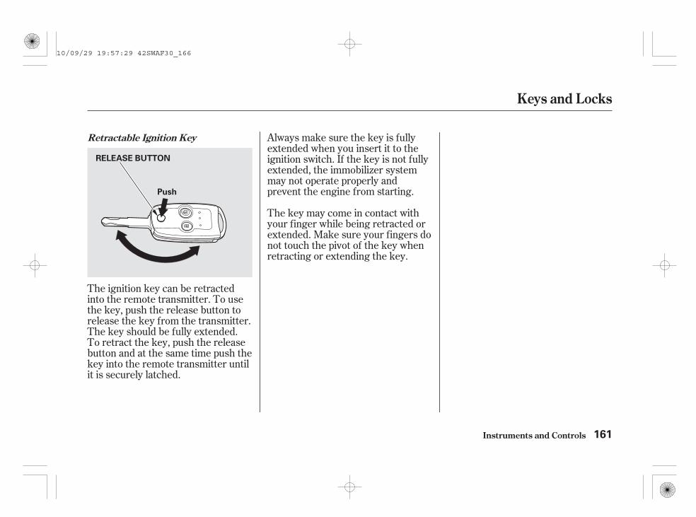
The ignition key can be retractedinto the remote transmitter. To usethe key, push the release button torelease the key from the transmitter.The key should be fully extended.To retract the key, push the releasebutton and at the same time push thekey into the remote transmitter untilit is securely latched.
Always make sure the key is fullyextended when you insert it to theignition switch. If the key is not fullyextended, the immobilizer systemmay not operate properly andprevent the engine from starting.
The key may come in contact withyour finger while being retracted orextended. Make sure your fingers donot touch the pivot of the key whenretracting or extending the key.
Retractable Ignition Key
Keys and Locks
Instruments and Controls 161
RELEASE BUTTON
Push
10/09/29 19:57:29 42SWAF30_166

If the system repeatedly does notrecognize the coding of your key,contact your dealer.
Do not attempt to alter this systemor add other devices to it. Electricalproblems could result that may makeyour vehicle inoperable.
If you have lost your key and cannotstart your engine, contact yourdealer.
The immobilizer system protectsyour vehicle from theft. If animproperly coded key (or otherdevice) is used, the engine’s fuelsystem is disabled.
When you turn the ignition switch tothe ON (II) position, the immobilizersystem indicator should come onbriefly, then go off. If the indicatorstarts to blink, it means the systemdoes not recognize the coding of thekey. Turn the ignition switch to theLOCK (0) position, remove the key,reinsert it, and turn the ignitionswitch to the ON (II) position again.
EC DirectivesThis immobilizer system complieswith the R & TTE (Radio equipmentand Telecommunications TerminalEquipment and the mutualrecognition of their conformity)Directives.
The system may not recognize yourkey’s coding if another immobilizerkey or other metal object (i.e. keychain) is near the ignition switchwhen you insert the key.
(South Africa model)
(EU models)
Immobilizer System
Instruments and Controls162
10/09/29 19:57:40 42SWAF30_167

-
-
-
-
If the front wheels are turned, theanti-theft lock may make it difficultto turn the key. Firmly turn thesteering wheel to the left or right asyou turn the key.
The ignition switch has fourpositions: LOCK (0), ACCESSORY(I), ON (II), and START (III).
You can insert orremove the key only in this position.To turn the key, push it in slightly. Ifyour vehicle has an automatictransmission, the shift lever mustalso be in park.
This is the normal keyposition when driving. Several of theindicators on the instrument panelcome on as a test when you turn theignition switch from theACCESSORY (I) to the ON (II)position.
On some types, the headlights comeon automatically in this position.
Use this positiononly to start the engine. The switchreturns to the ON (II) position whenyou let go of the key.
You will hear a reminder beeper ifyou leave the key in the ignitionswitch in the LOCK (0) or theACCESSORY (I) position and openthe driver’s door. You will also seethe symbol ‘‘ ,’’ or the symbolwith an ‘‘IGNITION KEY’’ messageon the multi-information display.Remove the key to turn off thebeeper and the warning symbol.
If equippedwith an audio system, cigarettelighter, or accessory power socket,they can be operated in this position.
CONTINUED
LOCK (0)
ON (II)
START (III)
ACCESSORY (I)
Ignition Switch
Instruments and Controls 163
10/09/29 19:57:52 42SWAF30_168

To lock the doors and the tailgate,push the top of the master door lockswitch on the driver’s door, pull thelock tab rearward on the driver’sdoor, or use the key on the outsidelock on the driver’s door.
If your vehicle has an automatictransmission, the shift lever must bein Park before you can remove thekey from the ignition switch.
Pushing the bottom of the masterdoor lock switch or pushing forwardthe lock tab on the driver’s door willunlock all doors and the tailgate.
Pushing the rear of either masterdoor lock switch will unlock all doorsand the tailgate. Pushing forward thelock tab on the driver’s door unlocksonly that door.
Except for South Africa models
On South Africa modelsPower Door Locks
Ignition Switch, Door Locks
Instruments and Controls164
Removing the key from theignition switch while drivinglocks the steering. This cancause you to lose control ofthe vehicle.
Remove the key from theignition switch only whenparked.
MASTER DOOR LOCK SWITCH
LockUnlock
10/09/29 19:58:02 42SWAF30_169

All doors and tailgate lock or unlockwhen you use the key to lock orunlock the driver’s door.
To lock any passenger’s door whengetting out of the vehicle, pull thelock tab rearward and close the door.To lock the driver’s door, remove thekey from the ignition switch, pull andhold the outside door handle, andpull the lock tab rearward or pushthe top of the master door lockswitch, then close the door.
Each door has a lock tab above theinner door handle. Pushing forwardor rearward the lock tab on eachpassenger’s door only locks andunlocks that door.
When the door is unlocked, you cansee the red indicator on the lock tababove the inner door handle.
To lock any passenger’s door whengetting out of the vehicle, pull thelock tab rearward and close the door.To lock the driver’s door, remove thekey from the ignition switch, pull thelock tab rearward or push the top ofthe master switch, then close thedoor.
CONTINUED
Except for South Africa models
On South Africa models
Except for South Africa models
Door Locks
Instruments and Controls 165
Left-hand drive type is shown.
Unlock
RED INDICATOR
LOCK TAB
Lock
10/09/29 19:58:14 42SWAF30_170

On vehicles with security systemExcept for South Africa models
On South Africa models
When you lock the doors and thetailgate with the key or the remotetransmitter, all outside turn signalsand both indicators in the instrumentpanel flash three times to verify thedoors and the tailgate are locked andthe security system has set (seepage ).
The security system activates afteryou lock the doors and the tailgatewith the lock tab on the driver’s dooror the master door lock switch (seepage ).
If you forget and leave the key in theignition switch, lockout preventionwill not allow you to lock the driver’sdoor. With any door or the tailgateopen and the key in the ignition,locking with master door lock switchis disabled. The lock tab on thedriver’s door is not disabled if thedriver’s door is closed. Pulling thedriver’s lock tab rearward will lockall doors and the tailgate. If you tryto lock an open driver’s door bypulling the lock tab rearward withthe outside handle pulled, the locktabs on all doors pop out and unlockthe doors.
All doors and the tailgate can belocked from the outside by using thekey in the driver’s door lock. Tounlock only the driver’s door, insertthe key, turn the key, and release it.The remaining doors and the tailgateunlock when you turn the key asecond time within a few seconds.
295
295
Lockout Prevention
Door Locks
Instruments and Controls166
10/09/29 19:58:23 42SWAF30_171

The super locking will not set if anydoor or the tailgate is not fully closed.It will be set even if the bonnet, orany window is open.
With the super locking set, themaster door lock switch on thedriver’s door and the lock tabs on alldoors are disabled.
You can also set the super lockingwith the remote transmitter. To set it,push the LOCK button twice within5 seconds (see page ).
To cancel the super locking, unlockthe driver’s door with the key or theremote transmitter.
Only the remote transmitter canreset the security system. Unlockingthe driver’s door with the keyactivates the alarm.
The super locking helps to protectyour vehicle and valuables from theft.To set the super locking, turn thekey towards the front of the vehicletwice within 5 seconds.
With any door and the tailgate openand the key in the ignition, lockingwith the master door lock switch isdisabled. The lock tab on the driver’sdoor is not disabled if the driver’sdoor is closed. Pulling the driver’slock tab rearward will lock all doorsand the tailgate. If you try to lock anopen driver’s door by pulling the locktab rearward, the lock tab on thedriver’s door pops out and unlocksthe driver’s door.
175
On vehicles with ultrasonic sensor
On South Africa models
CONTINUED
Super Locking(For some types)
Door Locks
Instruments and Controls 167
10/09/29 19:58:36 42SWAF30_172

On vehicles with ultrasonic sensor
On South Africa models only
If you set the super locking with thewindows open, the ultrasonic sensormay activate the alarm unexpectedlywhen the system senses strongvibrations on the vehicle or loudsound.
The auto door locking feature hasthree possible settings:
The auto door locking isdeactivated all the time.
Your vehicle has customizablesettings for the doors and tailgate toautomatically lock and unlock. Thereare default settings for each of thesefeatures. You can turn off or changethe settings for these features asdescribed on the following pages.
When you customize the setting,make sure your vehicle is parkedsafely, the engine is off, and theparking brake is applied. Make allsettings before you start driving.
All doors and tailgate lockwhenever you move the shift leverout of the Park (P) position (A/Tvehicles).
This is the factory setting.
The doors and tailgate lock whenthe vehicle speed reaches 15km/h (10 mph).
Auto Door Locking/UnlockingAuto Door Locking
Door Locks
Instruments and Controls168
If there are persons inside thevehicle with the superlocking set, they cannotunlock the doors from theinside.
Make sure there is no personinside the vehicle beforesetting the super locking.
10/09/29 19:58:50 42SWAF30_173
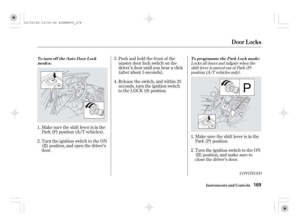
Turn the ignition switch to the ON(II) position, and open the driver’sdoor.
Push and hold the front of themaster door lock switch on thedriver’s door until you hear a click(after about 5 seconds).
Make sure the shift lever is in thePark (P) position.
Turn the ignition switch to the ON(II) position, and make sure toclose the driver’s door.
Make sure the shift lever is in thePark (P) position (A/T vehicles).
Release the switch, and within 20seconds, turn the ignition switchto the LOCK (0) position.
1.
2.
3.
4.
1.
2.
Locks all doors and tailgate when theshift lever is moved out of Park (P)position (A/T vehicles only).
CONTINUED
To turn off the Auto Door Lockmodes:
To programme the Park Lock mode:
Door Locks
Instruments and Controls 169
10/09/29 19:59:04 42SWAF30_174

Push and hold the front of themaster door lock switch on thedriver’s door. You will hear a click.Keep holding the switch until youhear another click (after about 5seconds).
Turn the ignition switch to the ON(II) position, and make sure toclose the driver’s door.
Turn the ignition switch to theLOCK (0) position.
Push and hold the front of themaster door lock switch on thedriver’s door. You will hear a click.Keep holding the switch until youhear another click (after about 5seconds).
Release the switch, and within 20seconds, turn the ignition switchto the LOCK (0) position.
Make sure the shift lever is in thePark (P) position (A/T vehicles).
push and hold thebrake pedal, and move the shiftlever out of the Park (P) position.
Release the switch, and within 20seconds, turn the ignition switchto the ACCESSORY (I) position.
move the shiftlever to the Park (P) position.
4.
5.
1.
2.
6.
3. 3.
4.
Locks all doors and the tailgate whenthe vehicle’s speed reaches about 15km/h (10 mph).
On A/T vehicles,
On A/T vehicles,
To programme the Drive Lock mode:
Door Locks
Instruments and Controls170
10/09/29 19:59:16 42SWAF30_175

The auto door unlocking feature hasfive possible settings:
The auto door unlocking isdeactivated all the time.
Release the switch, and within 20seconds, turn the ignition switchto the LOCK (0) position.
Push and hold the rear of themaster door lock switch on thedriver’s door. You will hear a click,and after about 5 seconds, you willhear another click.
Turn the ignition switch to the ON(II) position, and open the driver’sdoor.
All doors and tailgate unlockwhenever you turn the ignitionswitch to the ACCESSORY (I)position.
Make sure the shift lever is in thePark (P) position (A/T vehicles).
the driver’s doorunlocks when you move the shiftlever to the Park (P) position withthe brake pedal depressed.This is the default setting.
All doors and tailgate unlock whenyou move the shift lever to thePark (P) position with the brakepedal depressed (A/T vehicles).
The driver’s door unlockswhenever you turn the ignitionswitch to the ACCESSORY (I)position.This is the default setting on M/Tvehicles.
1.
2.
3.
4.
On A/T vehicles,
CONTINUED
Auto Door Unlocking
To turn off the Auto Door Unlockmodes:
Door Locks
Instruments and Controls 171
10/09/29 19:59:32 42SWAF30_176

Push and hold the rear of themaster door lock switch on thedriver’s door. You will hear a click.Continue to hold down the switch:
Turn the ignition switch to the ON(II) position, and make sure toclose the driver’s door.
Until you hear another click(after about 5 seconds) toactivate
Or, until you hear two moreclicks (after about 10 seconds)to activate
.
Turn the ignition switch to the ON(II) position, and make sure toclose the driver’s door.
Make sure the shift lever is in thePark (P) position.
Release the switch, and within 20seconds, turn the ignition switchto the LOCK (0) position.
Make sure the shift lever is in thePark (P) position (A/T vehicles).
1.
2.
3.
4.
2.
1.
Unlocks the driver’s door or all doorsand tailgate when the ignition switch ismoved out of the ON (II) position.
driver’s door unlockfeature.
all doors and tailgateunlock feature
Unlocks the driver’s door or all doorsand tailgate when the shift lever ismoved to Park (P) position with thebrake pedal depressed (A/T vehiclesonly).
To programme the Park Unlockmode:
To programme the Ignition SwitchUnlock mode:
Door Locks
Instruments and Controls172
10/09/29 19:59:45 42SWAF30_177

The childproof door locks aredesigned to prevent children seatedin the rear from accidentally openingthe rear doors. Each rear door has alock lever near the edge. With thelever in the LOCK position (lever isdown), the door cannot be openedfrom the inside regardless of theposition of the lock tab. To open thedoor, push the lock tab forward anduse the outside door handle.
Push and hold the rear of themaster door lock switch on thedriver’s door. You will hear a click.Continue to hold down the switch:
Or, until you hear two moreclicks (after about 10 seconds)to activate
.
Turn the ignition switch to theLOCK (0) position.
Until you hear another click(after about 5 seconds) toactivate
push and hold thebrake pedal, then move the shiftlever out of the Park (P) position.
Release the switch, and within 20seconds, turn the ignition switchto the ACCESSORY (I) position.
move the shiftlever to the Park (P) position.
3.
4.
5.
6.
all doors and tailgateunlock feature
driver’s door unlockfeature.
On A/T vehicles,
On A/T vehicles,
Childproof Door Locks
Door Locks
Instruments and Controls 173
unlock
lock
LEVER
10/09/29 19:59:57 42SWAF30_178

-
-
-
Press this button to lockall doors and the tailgate. When youpush the LOCK button, all outsideturn signals and both indicators inthe instrument panel flash threetimes to verify the doors and thetailgate are locked and the securitysystem (if equipped) has set. Youcannot lock the doors and thetailgate if any door or the tailgate isnot fully closed or the key is in theignition switch.
The front ceiling light (if the lightswitch is in the Door position) andrear ceiling light (if the light switchis in the centre position) will comeon when you press the UNLOCKbutton. If you do not open any dooror the tailgate within 30 seconds, thelights fade out. If you relock thedoors and tailgate with the remotetransmitter before 30 seconds haveelapsed, the lights will go offimmediately.
Press this button tounlock all doors and the tailgate.When you push the UNLOCK button,all outside turn signals, and bothindicators in the instrument panelflash once.
Press this button onceto unlock the driver’s door. Push ittwice to unlock the remaining doorsand the tailgate. All outside turnsignals and both indicators in theinstrument panel will flash oncewhen you press the button the firsttime.
Except for South Africa models
On South Africa models
LOCK
UNLOCK
UNLOCK
Remote Transmitter
Instruments and Controls174
LOCKBUTTON
UNLOCKBUTTON
LED
10/09/29 20:00:05 42SWAF30_179

If you do not open any door or thetailgate within 30 seconds, the doorsand the tailgate automatically relockand the security system (ifequipped) sets.
You cannot unlock the doors and thetailgate if the key is in the ignitionswitch.
You can set the super locking withthe remote transmitter. To set thesuper locking, push the LOCKbutton twice within 5 seconds.
The super locking will not set if anydoor or the tailgate is not fully closed.It will be set even if the bonnet orany window is open.
To cancel the super locking, pushthe UNLOCK button on the remotetransmitter, or unlock the driver’sdoor with the key.
See page for information on thesuper locking.
167
Super Locking(For some types)
Remote Transmitter
Instruments and Controls 175
If there are persons inside thevehicle with the superlocking set, they cannotunlock the doors from theinside.
Make sure there is no personinside the vehicle beforesetting the super locking.
10/09/29 20:00:16 42SWAF30_180

Avoid dropping or throwing thetransmitter.
Protect the transmitter fromextreme temperature.
Do not immerse the transmitter inany liquid.
If you lose a transmitter, thereplacement needs to bereprogrammed by your dealer.
If it takes several pushes on thebutton to lock or unlock the doorsand the tailgate, replace the batteryas soon as possible.
To replace the battery:
Battery type: CR1616
Remove the screw at the base ofthe transmitter with a smallPhillips-head screwdriver.
Be careful when removingthis screw as the head of the screwcan strip out.
Separate the keypad from thetransmitter by pushing any buttonfrom outside.
1.
2.
Remote Transmitter Care Replacing the TransmitterBattery
Remote Transmitter
Instruments and Controls176
NOTE:
SCREWKEYPAD
10/09/29 20:00:28 42SWAF30_181

+
This symbol on the batterymeans that this product mustnot be treated as householdwaste.
An improperly disposed of batterycan be harmful to the environmentand human health.Always confirm local regulations forbattery disposal.
Remove the old battery and notethe polarity. Make sure thepolarity of the new battery is thesame ( side facing down), theninsert it in the keypad.
Snap the two halves of the keypad,then install the parts in reverseorder.
Place a cloth on the edge of thekeypad to prevent scratches, andremove the upper half by carefullyprying on the edge with a smallflat-tip screwdriver.
3.
4.
5.
CONTINUED
Remote Transmitter
Instruments and Controls 177
BATTERY
10/09/29 20:00:39 42SWAF30_182

EC DirectivesThis keyless entry system complieswith the R & TTE (Radio equipmentand Telecommunications TerminalEquipment and the mutualrecognition of their conformity)Directives.
(South Africa model)(EU models)
Remote Transmitter
Instruments and Controls178
10/09/29 20:00:45 42SWAF30_183

To open the tailgate, push therelease, then lift up. To close thetailgate, use the inner handle to pullit down, then press down on the backedge.
Keep the tailgate closed at all timeswhile driving to avoid damaging thetailgate and to prevent exhaust gasfrom getting into the interior. See
on page.
The tailgate will lock or unlock whenyou lock or unlock the driver’s doorwith the key, the remote transmitter,the master door lock switch, or thelock tab on the driver’s door.
The tailgate will lock when you lockthe driver’s door with the key, theremote transmitter, the master doorlock switch, or the lock tab on thedriver’s door.To unlock the tailgate, turn the keyclockwise twice, push the rear of themaster door lock switch, or push theUNLOCK button twice on theremote transmitter.
76
Except for South Africa models
On South Africa models
Carbon Monoxide Hazard
Tailgate
Instruments and Controls 179
HANDLERELEASE
10/09/29 20:00:54 42SWAF30_184

Push the release lever to the lowerright as shown.
If the power door lock system cannotunlock the tailgate, unlock itmanually. In this case, you cannotopen the tailgate with the release.
Place a cloth on the top side of thecover to prevent scratches, then usea small flat-tip screwdriver to removethe cover on the back of the tailgate.
To open the tailgate, access thetailgate release lever from inside thevehicle.
If you need to open the tailgatemanually, it means there is aproblem with the tailgate. Have thevehicle checked by your dealer.
Opening the Tailgate Manually
Tailgate
Instruments and Controls180
Unlock
RELEASE LEVER
10/09/29 20:01:04 42SWAF30_185

-
Moves the seat forwardand backward.
Moves the front of theseat up or down.
Raises or lowers the seat.
Moves the whole seat upand forward, or downand backward. The frontof the seat also tilts up ordown at the same time.
Adjusts the seat-backangle forward orbackward.
Increases or decreasesthe lumbar support.
The controls for the poweradjustable driver’s seat are on theoutside edge of the seat bottom. Youcan adjust the seat with the ignitionswitch in any position. Make all seatadjustments before you start driving.
The front passenger’s seat can beadjusted manually (see the nextpage).
See pages for important safetyinformation and warnings about how toproperly position the seats and seat-backs.
On vehicles with power adjustabledriver’s seat
18 20Driver’s Seat Power Adjustments
Seats
Instruments and Controls 181
10/09/29 20:01:19 42SWAF30_186

-See pages for important safetyinformation and warnings about how toproperly position the seats and seat-backs.
18 20
Make all seat adjustments beforeyou start driving.
Once a seat is adjusted correctly,rock it back and forth to make sure itis locked in position.
To adjust the front or rear seatforward or backward, pull up on thebar under the seat cushion’s frontedge. Move the seat to the desiredposition, and release the bar. Try tomove the seat to make sure it islocked in position.
To change the seat-back angle of thefront seat, pull up the lever on theoutside of the seat bottom.
Manual Seat Adjustments
Seats
Instruments and Controls182
Driver’s seat is shown.
FRONT SEAT
SEAT-BACK ANGLEADJUSTMENT LEVER
10/09/29 20:01:29 42SWAF30_187

The angle of each rear seat-back canbe adjusted separately. To changethe seat-back angle of the rear seat-back, pull up on the release lever onthe top of the seat-back. Move theseat-back to the desired position,then release the lever. Make surethe seat-back latches in the newposition.
When using the centre seatingposition, adjust the left and right sideof the rear seats to the same position.
Make sure all rear shoulder belts arepositioned in front of the rear seat-backs after you adjust the rear seats.
The height of your driver’s seat isadjustable. To raise the seat,repeatedly pull up the lever on theoutside of the seat cushion. To lowerthe seat, push the lever downrepeatedly.
Driver’s Seat Height Adjustment(For some types)
Seats
Instruments and Controls 183
REAR SEAT
10/09/29 20:01:40 42SWAF30_188

Each front seat has an armrest onthe side of the seat-back. To use it,pivot it down.
The rear seat armrest is in thecentre of the rear seat. Pivot it downto use it.
A beverage holder is located in thearmrest.
The rear centre seat-back has aluggage area pass-through. To usethe luggage area pass-through, pullup the release on top of the centreseat-back and fold it down.
Armrests Luggage Pass-through
Seats
Instruments and Controls184
REARFRONT
10/09/29 20:01:51 42SWAF30_189

See page for important safetyinformation and a warning aboutimproperly positioning head restraints.
20
Your vehicle is equipped with headrestraints in all seating positions tohelp protect you and yourpassengers from the likelihood ofwhiplash and other injuries.
If your vehicle is equipped with adual deck luggage shelf, do not usethe shelf when any seat-back isfolded down. Objects placed on thisshelf can be thrown forward andoccupants can be injured duringsudden stops or a collision.
For more information on the dualdeck luggage shelf, see page .
They are most effective when youadjust them so the centre of the backof the occupant’s head rests againstthe centre of the restraint.
200
CONTINUED
Head Restraints
Seats
Instruments and Controls 185
10/09/29 20:02:00 42SWAF30_190

The head restraints adjust for height.You need both hands to adjust therestraint. Do not attempt to adjust itwhile driving. To raise it, pull upward.To lower the restraint, push therelease button sideways, and pushthe restraint down.
When a passenger is seated in therear seating position, make sure therear head restraint is adjusted to itshighest position.
Adjusting the Head Restraint
Seats
Instruments and Controls186
Rear Outer Position
RELEASE BUTTON
Front Position Rear Centre PositionCUSHION
CUSHION
RELEASEBUTTON
LEGSLEGS LEGS
SEAT-BACK SEAT-BACK RELEASE BUTTON
CUSHION
SEAT-BACK
10/09/29 20:02:09 42SWAF30_191

The driver’s and front passenger’sseats have active head restraints. Ifthe vehicle is struck severely fromthe rear, the occupant properlysecured with the seat belt will bepushed against the seat-back and thehead restraint will automaticallymove forward.Always replace the rear head
restraints when the seat-backs arereturned to upright position.
Make sure the head restraint locksin position when you reinstall it.
When reinstalling a head restraint,put the legs back in place. Thenadjust it to the appropriate heightwhile pressing the release button.
Make sure the removed headrestraints are securely stored.
To remove a head restraint, pull it upas far as it will go. Push the releasebutton and pull the restraint out ofthe seat-back.
CONTINUED
Active Head RestraintsRemoving the Head Restraint
Seats
Instruments and Controls 187
Failure to reinstall the headrestraints can result in severeinjury during a crash.
Always replace the headrestraints before driving.
10/09/29 20:02:20 42SWAF30_192

This reduces the distance betweenthe restraint and the occupant’s head.It also helps protect the occupantsagainst the likelihood of whiplashand injuries to the neck and upperspine.
For a head restraint system to workproperly:
Do not hang any items on the headrestraints, or from the restraintlegs.
Do not place any object betweenan occupant and the seat-back.
Install each restraint in its properlocation.
Only use genuine Hondareplacement head restraints.
If the restraints do not return to theirnormal position, or in the event of asevere collision, have the vehicleinspected by a Honda dealer.
After a collision, the activatedrestraint should return to its normalposition.
Seats
Instruments and Controls188
10/09/29 20:02:30 42SWAF30_193

Adjust the rear seats as far backas possible.
Remove the front head restraints(see page ), and store themsecurely.
You can recline the seat-backs on thefront seats so they are level with therear seat cushions, making a largecushioned area. To do this:
Adjust the front seats forward asfar as possible. Pull up the seat-back angle adjustment lever andpivot the seat-back backward untilit is level with the rear seatcushion.
If your vehicle has the poweradjustable driver’s seat, only thepassenger’s side can be level asfollows.
The seat-back of the poweradjustable driver’s seat cannot belevel. Do not push the seat-backdown forcibly.
Adjust the rear seat-back to thedesired position.
When you return the seat-back to itsupright position, hold the seat-backto keep it from going up too quickly.
Reverse this procedure to return thefront and rear seats to the uprightposition. Make sure you install thehead restraints and securely lock theseats before driving.
1.
2.
3.
4.
187On some models
On some models
CONTINUED
Reclining the Front Seats
Seats
Instruments and Controls 189
SLIDE BAR
SEAT-BACK ANGLEADJUSTMENT LEVER
10/09/29 20:02:44 42SWAF30_194

Each rear seat-back can be foldeddown separately to give moreluggage room. With either of theouter seat-backs folded-down, youcan still carry a passenger in the rearseat. With the centre seat-backfolded-down, either outer seatingposition can be used.
You can also fold up the left or rightside of the rear seats separately tocreate further luggage space (seepage ).
Remove any items from the seatbefore folding down the seat-back.
Push the seat belt buckles into theseat cushion.
Always replace the rear headrestraints when the seat-backs arereturned to upright position.
1.192
Folding the Rear Seats Down
Seats
Instruments and Controls190
Make sure the seat-backs arelatched securely beforedriving.
BUCKLE
10/09/29 20:02:54 42SWAF30_195

Make sure the rear seat armrest isstored.
Reverse this procedure to return theseat-back to the upright position.Make sure the seat is secured andthe seat belt is in front of the seat-back before driving.
In the rear centre seating position,be sure the detachable anchor islatched securely (see page ).
Do not put any heavy items on theseat-back when it is folded down.
Pull up the release lever on the topof the seat-back.
Fold the seat-back forward.
When you are folding the rear centreseat-back, use the latch plate torelease the centre seat belt from thedetachable anchor (see page ).Allow the seat belt to retract into theholder on the ceiling and store thebuckles in it.
Lower the rear head restraint toits lowest position.
2.
3.
4.
194
194
CONTINUED
Seats
Instruments and Controls 191
Make sure the seat-backs arelatched securely beforedriving.
LATCH PLATE RELEASE LEVER
10/09/29 20:03:07 42SWAF30_196

When any seat-back is folded down,do not use the dual deck luggageshelf (if equipped).
Make sure all items in the luggagearea are secured. Loose items can flyforward and cause injury if you haveto brake hard (See
on page ).
Remove any items from the seatbefore you fold up the seat cushion.
To fold the rear seat forward:
Pull up the bar under the seatcushion and slide the rear seatbackward. The rear seat will notfold forward unless it is as farback as it will go.
The left and right rear seats can befolded up separately to make roomfor luggage.
Lower the centre seat-back beforefolding the right side seat forward.
Follow steps 1 through 4 on pagesand for folding down the
seat-back.
1.
2.190 191
365Carrying
Luggage
Folding the Rear Seat Forward
Seats
Instruments and Controls192
SLIDE BARS
10/09/29 20:03:20 42SWAF30_197

You cannot fold up the rear seat ifit is not latched securely in therearmost position.
Pull out the fastening strap fromthe slit on the seat-back. Thenattach the anchor on the fasteningstrap to the hook on the centrepillar.
Pull down on the anchor to engagethe upper part of the anchorsecurely on the hook, and makesure the seat is secure.
Unlock the seat from the floor bypulling the lock release strapunder the seat cushion’s backedge, then lift the rear of the seat.
Reverse this procedure to return theseat to the upright position.Make sure the seat is securelylatched before driving.When you are not using thefastening strap, store the strap intothe slit on the seat-back.
3. 4. 5.
CONTINUED
Seats
Instruments and Controls 193
LOCK RELEASE STRAP
ANCHOR
HOOK
ANCHOR
HOOK
FASTENING STRAPFASTENINGSTRAP
10/09/29 20:03:31 42SWAF30_198

Make sure both outer seat belts arepositioned in side of the rear seat-backs.
In the centre seating position of therear seat, be sure the detachableanchor is latched securely beforeusing the seat belt (see page ).
Make sure all items in the luggagearea are secured. Loose items can flyforward and cause injury if you haveto brake hard (See
on page ).
Do not use the dual deck luggageshelf (if equipped) when the seatsare folded down or forward.
The seat belt in the rear centre seatis equipped with a detachable anchor.
This allows the centre seat belt to beunlatched when the rear centre seatback is folded down or the right siderear seat is folded forward.
195
365Carrying
Luggage
Detachable Anchor
Seats
Instruments and Controls194
Make sure the seat-backs arelatched securely beforedriving.
Using the seat belt with thedetachable anchor unlatchedincreases the chance ofserious injury or death in acrash.
Before using the seat belt,make sure the detachableanchor is correctly latched.
DETACHABLE ANCHOR
10/09/29 20:03:40 42SWAF30_199

Pull out the small latch plate and thelatch plate from each holding slot inthe ceiling, and pull out the seat beltto extend it.
Tug on the seat belt to verify thatthe detachable anchor is securelylatched. Make sure the seat belt isnot twisted.
Line up the triangle marks on thesmall latch plate and anchor bucklewhen reattaching the belt and buckle.
To unlatch the detachable anchor,insert the latch plate into the slot onthe side of the anchor buckle. Storethe detachable anchor and seat beltlatch plates in the retractor housing.
Seats
Instruments and Controls 195
TRIANGLEMARKS
ANCHOR BUCKLE
SMALL LATCH PLATE
LATCH PLATE
ANCHOR BUCKLE
LATCH PLATE
10/09/29 20:03:50 42SWAF30_200

Push the front of the switch, HI, torapidly heat up the seat. After theseat reaches a comfortabletemperature, select LO by pushingthe back of the switch. This will keepthe seat warm.
In the HI setting, the heater turns offwhen the seat gets warm, and turnsback on after the seat’s temperaturedrops.
Follow these precautions wheneveryou use the seat heaters:
Use the HI setting only to heat theseats quickly, because it drawslarge amounts of current from thebattery.
If the engine is left idling for anextended period, do not use theseat heaters, even on the LOsetting. It can weaken the battery,causing hard starting.
Both front seats are equipped withseat heaters. The ignition switchmust be in the ON (II) position touse the heaters.
In the LO setting, the heater runscontinuously. It does not cycle withtemperature changes.
Seat Heaters (For some types)
Instruments and Controls196
SEAT HEATER SWITCHES
10/09/29 20:04:01 42SWAF30_201
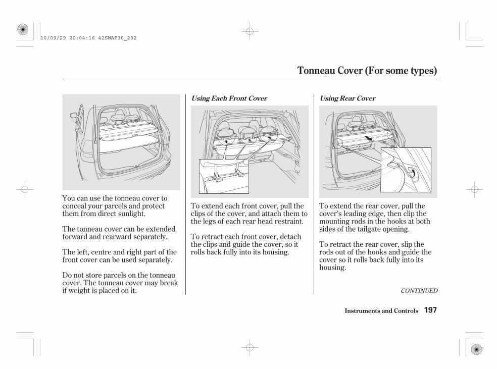
To extend each front cover, pull theclips of the cover, and attach them tothe legs of each rear head restraint.
To retract each front cover, detachthe clips and guide the cover, so itrolls back fully into its housing.
To extend the rear cover, pull thecover’s leading edge, then clip themounting rods in the hooks at bothsides of the tailgate opening.
To retract the rear cover, slip therods out of the hooks and guide thecover so it rolls back fully into itshousing.
You can use the tonneau cover toconceal your parcels and protectthem from direct sunlight.
The tonneau cover can be extendedforward and rearward separately.
The left, centre and right part of thefront cover can be used separately.
Do not store parcels on the tonneaucover. The tonneau cover may breakif weight is placed on it. CONTINUED
Using Each Front Cover Using Rear Cover
Tonneau Cover (For some types)
Instruments and Controls 197
10/09/29 20:04:16 42SWAF30_202

You can store the tonneau coverhousing on the luggage area floor tomake a large room.
Retract all covers fully into thetonneau cover housing.
Release each side of the tonneaucover housing unit by pushing theleft end of the unit toward theright end and lifting it upward.
Lower the right end of the unit,and insert it into the holder on theright side panel.
While pushing the right end of thehousing unit to the right holder,lower the left end through theopening on the left side panel.
1.
2.
3. 4.
Storing the Tonneau Cover HousingUnit
Tonneau Cover (For some types)
Instruments and Controls198
10/09/29 20:04:27 42SWAF30_203

While pushing the left end, installthe right side of the housing unitin the holder on the lower rightside panel.
Make sure the housing unit issecurely placed so it will not comeloose while you are driving.
Reverse this procedure to install thetonneau cover housing unit in place.
To remove the tonneau coverhousing unit from the vehicle, followstep 3, then take it out while pushingthe right end of the housing. Do notpull it out forcibly.
Do not put heavy weight on thetonneau cover housing unit. Thismay damage it.
5.
Tonneau Cover (For some types)
Instruments and Controls 199
10/09/29 20:04:37 42SWAF30_204
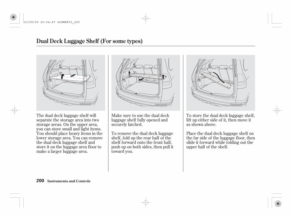
The dual deck luggage shelf willseparate the storage area into twostorage areas. On the upper area,you can store small and light items.You should place heavy items in thelower storage area. You can removethe dual deck luggage shelf andstore it on the luggage area floor tomake a larger luggage area.
Make sure to use the dual deckluggage shelf fully opened andsecurely latched.
To remove the dual deck luggageshelf, fold up the rear half of theshelf forward onto the front half,push up on both sides, then pull ittoward you.
To store the dual deck luggage shelf,lift up either side of it, then move itas shown above.
Place the dual deck luggage shelf onthe far side of the luggage floor, thenslide it forward while folding out theupper half of the shelf.
Dual Deck Luggage Shelf (For some types)
Instruments and Controls200
10/09/29 20:04:47 42SWAF30_205

The dual deck luggage shelf can beplaced on the floor as shown above.
Reverse this procedure to return thedual deck luggage shelf to the upperposition. Make sure the dual deckluggage shelf is latched securely.
When any of the rear seats arefolded down or forward, do not placeany objects on the dual deck luggageshelf. Make sure to store the shelfon the luggage area floor. It could beunlatched during a crash.
The maximum load on the dual deckluggage shelf is 10 kg. This is shownon a label on the left side of the dualdeck luggage shelf (see next page).To prevent damage to the dual deckluggage shelf, do not exceed themaximum load.
Make sure all items in the luggagearea are secured. Loose items can flyforward and cause injury if you haveto brake hard (See
on page ).365
CONTINUED
CarryingLuggage
Dual Deck Luggage Shelf (For some types)
Instruments and Controls 201
Do not use this shelf if thesecond row seats are foldeddown.
Objects placed on the shelfcould be thrown forwardduring a crash or sudden stopand hurt someone.
10/09/29 20:04:57 42SWAF30_206

To prevent damage, do not placemore than 10 kg on this shelf.
To remind you of how to use thedual deck luggage shelf properly, alabel shown below is attached to theshelf.
Dual Deck Luggage Shelf (For some types)
Instruments and Controls202
10/09/29 20:05:03 42SWAF30_207
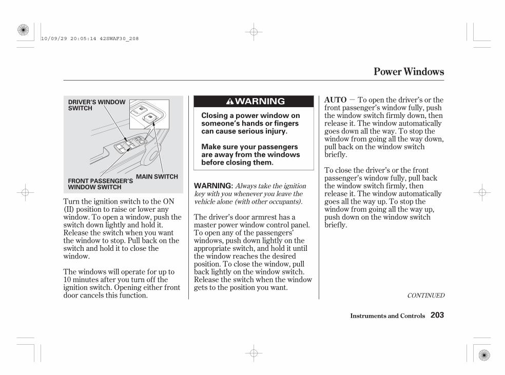
-
Turn the ignition switch to the ON(II) position to raise or lower anywindow. To open a window, push theswitch down lightly and hold it.Release the switch when you wantthe window to stop. Pull back on theswitch and hold it to close thewindow.
The windows will operate for up to10 minutes after you turn off theignition switch. Opening either frontdoor cancels this function.
The driver’s door armrest has amaster power window control panel.To open any of the passengers’windows, push down lightly on theappropriate switch, and hold it untilthe window reaches the desiredposition. To close the window, pullback lightly on the window switch.Release the switch when the windowgets to the position you want.
To open the driver’s or thefront passenger’s window fully, pushthe window switch firmly down, thenrelease it. The window automaticallygoes down all the way. To stop thewindow from going all the way down,pull back on the window switchbriefly.
To close the driver’s or the frontpassenger’s window fully, pull backthe window switch firmly, thenrelease it. The window automaticallygoes all the way up. To stop thewindow from going all the way up,push down on the window switchbriefly.
Always take the ignitionkey with you whenever you leave thevehicle alone (with other occupants).
CONTINUED
AUTO
Power Windows
Instruments and Controls 203
Closing a power window onsomeone’s hands or fingerscan cause serious injury.
Make sure your passengersare away from the windowsbefore closing them.
WARNING:
MAIN SWITCH
DRIVER’S WINDOWSWITCH
FRONT PASSENGER’SWINDOW SWITCH
10/09/29 20:05:14 42SWAF30_208

- If either of thefront windows runs into any obstaclewhile it is closing automatically, itwill stop, and then reverse direction.To close the window, remove theobstacle, then use the window switchagain.
Auto reverse stops sensing when thewindow is almost closed. You shouldalways check that all passengers andobjects are away from the windowbefore closing it.
When you push the MAIN switch in,the switch is off, and the passengers’windows cannot be raised or lowered.To cancel this feature, push on theswitch again to get it to pop out.Keep the MAIN switch pushed inwhen you have children in thevehicle so they do not injurethemselves by operating thewindows unintentionally.
To open or close the driver’s or thefront passenger’s window partially,push down or pull back on thewindow switch lightly and hold it.The window will stop when yourelease the switch.
The driver’s window autoreverse function is disabled whenyou continuously pull up the switch.
AUTO REVERSE
Power Windows
Instruments and Controls204
NOTE:
10/09/29 20:05:22 42SWAF30_209

-
The sunroof can be tilted up in theback for ventilation, or it can be slidback into the roof. Use the switch onthe front ceiling to operate thesunroof. You must turn the ignitionswitch to the ON (II) position tooperate the sunroof.
To tilt up the back of the sunroof,push on the centre of the sunroofswitch. To stop the sunroof tilting upfully, push the switch briefly.
To open the sunroof fully,pull back the sunroof switch firmly,then release it. The sunroofautomatically opens all the way. Tostop the sunroof from opening, pushthe switch briefly.
To close the sunroof fully, pushforward the sunroof switch firmly,then release it. The sunroofautomatically closes all the way. Tostop the sunroof from closing, pushthe switch briefly.
To open the sunroof, pull back onthe switch lightly and hold it.Release the switch when the sunroofreaches the desired position. Pushthe switch forward lightly and hold itto close the sunroof. Release theswitch to stop the operation.
CONTINUED
AUTO
Sunroof (For some types)
Instruments and Controls 205
Opening or closing thesunroof on someone’s handsor fingers can cause seriousinjury.
Make sure all hands andfingers are clear of thesunroof before opening orclosing it.
SUNROOF SWITCH
TILT
10/09/29 20:05:32 42SWAF30_210

- If the sunroofruns into any obstacle while it isclosing automatically, it will reversedirection and then stop. To close thesunroof, remove the obstacle, thenuse the sunroof switch again.
Auto reverse stops sensing when thesunroof is almost closed. You shouldalways check that all passengers andobjects are away from the sunroofbefore closing it.
The sunroof has a key-off delay. Youcan still open and close the sunrooffor up to 10 minutes after you turnoff the ignition switch. The key-offdelay cancels as soon as you openeither front door.
If you try to open the sunroof inbelow-freezing temperatures, orwhen it is covered with snow or ice,you can damage the sunroof panel orits motor.
On some models Always take the ignitionkey with you whenever you leave thevehicle alone (with other occupants).
Extending the head, armsor other parts of the body through thesunroof while the vehicle is moving cancause serious injury or death.
AUTO REVERSE
Sunroof (For some types)
Instruments and Controls206
WARNING:
WARNING:
10/09/29 20:05:41 42SWAF30_211

Both of the front and rear sunshadescan be opened. The front sunshadeis rolled up in the centre holder fromfront to rear, and the rear sunshadefrom rear to front at the same time.Use the switch on the front ceiling tooperate the sunshades. You mustturn the ignition switch to the ON(II) position to operate thesunshades.
To open the sunshades, push theswitch backward and hold it. Toclose them, push the switch forwardand hold it. Release the switch whenthe sunshades reach the desiredposition, or to stop the operation.
The front and rear sunshades canonly be opened or closed together.
Always take the ignitionkey with you whenever you leave thevehicle alone (with other occupants).
CONTINUED
Sunshades (For some types)
Instruments and Controls 207
Opening or closing thesunshade on someone’shands or fingers may causeinjury.
Make sure all hands andfingers are clear of thesunshade before opening orclosing it.
WARNING:
10/09/29 20:05:51 42SWAF30_212

-- If either of thefront and rear sunshades runs intoany obstacle while they are closingautomatically, each sunshade willreverse direction and then stop. Toclose the sunshades, remove theobstacle, then use the sunshadeswitch again.
Auto reverse stops sensing wheneach sunshade is almost closed. Youshould always check that allpassengers and objects are awayfrom the sunshades before closingthem.
The sunshades have a key-off delay.You can still open and close thesunshades for up to 10 minutes afteryou turn off the ignition switch. Thekey-off delay cancels as soon as youopen either front door.
To open the sunshadesfully, push the switch backwardfirmly, then release it. Thesunshades automatically open all theway. To stop the sunshades fromopening, push the switch briefly.
To close the sunshade fully, push theswitch forward firmly, then release it.The sunshades automatically closeall the way. To stop the sunshadesfrom closing, push the switch briefly.
To open or close the sunshadespartially, push the sunshade switchbackward or forward lightly and holdit. The sunshade will stop when yourelease the switch.
AUTO REVERSEAUTO
Sunshades (For some types)
Instruments and Controls208
10/09/29 20:05:59 42SWAF30_213

Keep the inside and outside mirrorsclean and adjusted for best visibility.Be sure to adjust the mirrors beforeyou start driving.
The inside mirror has day and nightpositions. The night position reducesglare from headlights behind you.Flip the tab on the bottom edge ofthe mirror to select the day or nightposition.
The inside mirror can automaticallydarken to reduce glare. To turn onthis feature, press the button on thebottom of the mirror. The AUTOindicator comes on as a reminder.When it is on, the mirror darkenswhen it senses the headlights of avehicle behind you, then returns tonormal visibility when the lights aregone. Press the button again to turnoff this feature.
There is also a sensor on the back ofthe mirror. Items hung on the mirrormay block this sensor and affect itsperformance.
On some models
Mirrors
Instruments and Controls 209
TAB
INDICATOR
AUTO BUTTON
SENSOR
10/09/29 20:06:08 42SWAF30_214

Turn the ignition switch to the ON(II) position.
Move the selector switch to L (leftside) or R (right side).
Push the appropriate edge of theadjustment switch to move themirror right, left, up, or down.
When you finish, move theselector switch to the centre (off)position. This turns off theadjustment switch to keep yoursettings.
The passenger’s outside mirror has areverse tilt feature. When in reverse,the mirror will tilt down slightly toimprove your view as you parallelpark. Shifting out of reverse willreturn the mirror to its originalposition.
Make sure to turn the ignition switchto the ON (II) position to use thisfeature.
To tilt the passenger’s mirror,place the power mirror selectorswitch in the passenger’s sideposition.
To turn the feature off, place theswitch in the centre position or thedriver’s side position.
1.
2.
3.
4.
Adjusting the Power Mirrors(For some types)Reverse Tilt Door Mirror
Mirrors
Instruments and Controls210
SELECTOR SWITCH
ADJUSTMENT SWITCH
10/09/29 20:06:21 42SWAF30_215

Door mirrors can be folded by thefolding switch next to the selectorswitch, which enables you to parkyour vehicle in a limited parkingspace easily. Make sure you fold outthe mirrors before you start driving.With the ignition switch in the ON(II) position, press the folding switchto fold up both outside mirrors simul-taneously. To fold out, press theswitch again.
The outside mirrors are heated toremove fog and frost. With theignition switch in the ON (II)position, turn on the heaters bypressing the rear window demisterbutton. The indicator in the buttoncomes on as a reminder. Press thebutton again to turn the heaters andthe demister off.
On some types, this heated mirrorfunction has a timer (see page ).156
CONTINUED
Folding Door Mirrors(For some types)
Power Mirror Heaters(For some types)
Mirrors
Instruments and Controls 211
Automatic air conditioning type FOLDING SWITCH
REAR WINDOW DEMISTER/HEATED MIRROR BUTTON
REAR WINDOW DEMISTER/HEATED MIRROR BUTTON
Manual heating/air conditioning type
10/09/29 20:06:35 42SWAF30_216

Driving the vehicle with the parkingbrake applied can damage the rearbrakes and hubs. A beeper willsound if the vehicle is driven withthe parking brake on.
To apply the parking brake, pull thelever up fully. To release it, pull upslightly, push the button, and lowerthe lever. The parking brakeindicator on the instrument panelshould go out when the parkingbrake is fully released (see page ).
Never drive your vehicle with theoutside mirrors folded.
You will also see the symbol ‘‘ ,’’or this symbol with a ‘‘RELEASEPARKING BRAKE’’ message on themulti-information display.
88
Parking Brake
Mirrors, Parking Brake
Instruments and Controls212
PARKING BRAKE LEVER
10/09/29 20:06:44 42SWAF30_217

*
*
*
*
*
*
*
Interior Convenience Items
Instruments and Controls 213
SUN VISORVANITY MIRROR
: If equipped
ACCESSORY POWER SOCKET
TONNEAU COVER
COAT HOOK DOOR BEVERAGE HOLDERS
UPPER GLOVE BOX
DUAL DECK LUGGAGE SHELF
CENTRE CONSOLE withBEVERAGE HOLDERSBEVERAGE HOLDERS in
REAR SEAT ARMREST
ACCESSORYPOWER SOCKET
AUXILIARY INPUT JACK
CIGARETTELIGHTER
SUNGLASSES HOLDERCONVERSATION MIRROR
ASHTRAY
LOWER GLOVE BOX
CENTRE POCKETS
10/09/29 20:06:50 42SWAF30_218

Open the upper glove box bypushing up the lever. Close it bypulling down on the edge under thelever.
Open the lower glove box by pullingthe bottom of the handle. Close itwith a firm push.
You can lock or unlock the glove boxwith the ignition key.
On some types, the glove box lightcomes on only when the positionlights are on.
Lower Glove Box Upper Glove Box
Interior Convenience Items
Instruments and Controls214
An open glove box can causeserious injury to yourpassenger in a crash, even ifthe passenger is wearing theseat belt.
Always keep the glove boxclosed while driving.
To lock
LEVERLOWER GLOVE BOX
EDGE
10/09/29 20:07:01 42SWAF30_219

Be careful when you are using thebeverage holders. A spilled liquidthat is very hot can scald you or yourpassengers. Liquid can also spillfrom the door pocket beverageholders when you open or close thedoors. Use only resealablecontainers in the door pockets.
Spilled liquids can damage theupholstery, carpeting, and electricalcomponents in the interior.
The front beverage holder is in thecentre console compartment.
The rear seat also has a beverageholder in the centre armrest. To useit, pivot the armrest down.
Beverage Holders
Interior Convenience Items
Instruments and Controls 215
FRONT REAR
BEVERAGE HOLDER
10/09/29 20:07:10 42SWAF30_220

To use an accessory power socket,the ignition switch must be in theACCESSORY (I) or ON (II) position.They will not power an automotivetype cigarette lighter element.
Your vehicle has two accessorypower sockets.Each socket is intended to supplypower for 12 volt DC accessoriesthat are rated 120 watts or less (10amps).
It is recommended that theseaccessory sockets are used forgenuine Honda accessories.
Make sure to put the socket coverback in place to prevent any smallforeign objects from getting into thesocket.
When more than one socket is beingused, the combined power rating ofthe accessories should be 120 wattsor less (10 amps).
Accessory Power Sockets
Interior Convenience Items
Instruments and Controls216
FRONT REAR
10/09/29 20:07:21 42SWAF30_221

To open the sunglasses holder, pushthen release the raised detent. It willunlatch and swing down. To close it,push it until it latches. Make sure theholder is closed while you are driving.
Some larger styles of sunglassesmay not fit in the holder.
You may also store small items inthis holder. Make sure they aresmall enough to let the holder closeand latch, and that they are notheavy enough to cause the holder topop open while driving.
To open or close the consolecompartment, slide the lid rearwardor forward.
There is a sunglasses holder in theconsole compartment. Slide itforward or rearward to access thelower part of the compartment.
On some types
CONTINUED
Console Compartment Sunglasses Holder
Interior Convenience Items
Instruments and Controls 217
Push
SUNGLASSES HOLDER
10/09/29 20:07:35 42SWAF30_222

On some typesThe sunglasses holder uses a convexmirror for its bottom panel. You cansee all the vehicle passengers in thismirror. To use the mirror, open thesunglasses holder fully, push it to thefirst detent, and release it.
To switch back to the sunglassesholder, close the conversation mirrorand then open the sunglasses holder.
The sunglasses holder is located inthe centre console compartment.
To use a coat hook, slide it outslightly, then pull it down.
Make sure the coat hook is pulled upwhen you are not using it. This hookis not designed for large or heavyitems.
Conversation Mirror(For some types)
Coat Hook
Interior Convenience Items
Instruments and Controls218
SUNGLASSES HOLDER COAT HOOK
10/09/29 20:07:47 42SWAF30_223

To use the sun visor, pull it down.You can also use the sun visor at theside window. Remove the supportrod from the clip and swing the sunvisor toward the side window.
Pull up the vanity mirror cover to useit.
The light comes on when you pull upthe cover.
Make sure you put the sun visorback in place when you are gettinginto or out of the vehicle.
Make sure you close the cover whenyou are not using the vanity mirror.The vanity mirror light will not comeon if the sun visor is moved to theside window.
The ignition switch must be in theACCESSORY (I) or ON (II) positionfor the cigarette lighter to work. Toheat up the lighter, push it in. It willpop out when it is ready for use. Donot hold the lighter in while it isheating up, you could cause it tooverheat.
On some types
CONTINUED
Sun Visor Vanity Mirror Cigarette Lighter
Interior Convenience Items
Instruments and Controls 219
SUN VISOR CIGARETTE LIGHTER
10/09/29 20:08:02 42SWAF30_224

Use the ashtray only for cigarettes,cigars, and other smoking materials.To prevent a possible fire anddamage to your vehicle, don’t putpaper or other things that can burnin the ashtray.
Do not try to insert any device otherthan the cigarette lighter in thesocket. If you use any other device,the socket will be damaged and youwill no longer be able to keep thecigarette lighter locked in the socket.
A removable ashtray is equippedwith your vehicle. The ashtray fits inthe beverage holders. To open it, pullup on the lid.
Ashtray
Instruments and Controls
Interior Convenience Items
220
ASHTRAY
10/09/29 20:08:10 42SWAF30_225

Remove the key from the ignitionswitch. If you do not open a door,the light fades out in about 30seconds.
The ceiling light has a three-positionswitch: ON, Door Activated, andOFF. In the Door Activated (centre)position, the light comes on whenyou:
Open any door.
After all doors are closed tightly, thelight dims slightly, then fades out inabout 30 seconds. The light turns offbefore 30 seconds have elapsed ifyou insert the key to the ignitionswitch.
If you leave any door open withoutthe key in the ignition switch, theceiling light will go off after 3minutes.
Unlock the doors and the tailgatewith the key or remote transmitter.
Turn on a spotlight by pushing thelens. Push the lens again to turn itoff. You can use the spotlights at alltimes.
CONTINUED
Ceiling Light Spotlights
All Models
Interior Lights
Instruments and Controls 221
OFF
ON
DOOR ACTIVATED
Push
Push
On vehicles without sunshades
10/09/29 20:08:24 42SWAF30_226

The spotlights have a two-positionswitch. In the DOOR position, thelights come on when you open anydoor. In the OFF position, the lightsdo not come on.
The spotlights (with the switch inthe DOOR position) also come onwhen you unlock the door with thekey or the remote transmitter, andwhen you remove the key from theignition switch.
The luggage area light has a three-position switch. In the OFF position,the light does not come on. In thecentre position, it comes on whenyou open the tailgate. In the ONposition, it stays on continuously.
On vehicles with sunshades
Luggage Area Light
Interior Lights
Instruments and Controls222
On vehicles with sunshades
Push
TAILGATE ACTIVATED
ON
OFF
POSITION SWITCH
Push
10/09/29 20:08:33 42SWAF30_227

The ignition switch light comes onwhen you open the driver’s door, andfades out in about 30 seconds afteryou close the door.
The courtesy light between thespotlights comes on when you turnthe position lights on. To adjust itsbrightness, turn the instrumentpanel brightness control knob on thedashboard, with the ignition switchin the ON (II) position (see page
).155
Courtesy LightIgnition Switch Light
Interior Lights
Instruments and Controls 223
COURTESY LIGHT
On vehicles with sunshades or sunroofOn vehicles without sunshadesor sunroof
COURTESY LIGHT
10/09/29 20:08:42 42SWAF30_228

224
10/09/29 20:08:45 42SWAF30_229

The heating and air conditioningsystem in your vehicle provides acomfortable driving environment inall weather conditions.
The standard audio system on somemodels has many features. Thissection describes those features andhow to use them.
Your vehicle has an anti-theft audiosystem that requires a code numberto enable it.
The security system helps todiscourage vandalism and theft ofyour vehicle.
.............Vents, Heating, and A/C . 226...........................Using the A/C . 231
...............Climate Control System . 233Sunlight and Temperature
...................................Sensors . 241................................Audio System . 243
..........................Playing the Radio . 245.....................Adjusting the Sound . 255
................................Playing a Disc . 256Disc Player/Changer Error
...................................Messages . 267Optional Disc Changer Error
...................................Messages . 268..................Protecting Your Discs . 269
............................Playing an iPod . 272.................iPod Error Messages . 278
Playing a USB Flash Memory........................................Device . 279
USB Flash Memory Device Error...................................Messages . 288
................Remote Audio Controls . 289......................Auxiliary Input Jack . 290
.................Radio Theft Protection . 291..........................Setting the Clock . 293
............................Security System . 295...............................Cruise Control . 298
..............Adaptive Cruise Control . 301................Parking Sensor System . 319
...Rearview Camera and Monitor . 324Hands-Free Telephone (HFT)
........................................System . 325
On some types
On some types
Features
Features 225
10/09/29 20:08:54 42SWAF30_230

The direction of airflow from thevents in the centre and each cornerof the dashboard is adjustable.
To adjust the airflow from each vent,move the tab up-and-down and side-to-side.
The engine must be running for theheater and air conditioning togenerate hot and cold air.
Proper use of the heating andcooling system can make the interiordry and comfortable, and keep thewindows clear for the best visibility.
The vents in the corners of thedashboard can be opened and closedwith the dials underneath them.
On vehicles with manual heating/airconditioning system
Vents, Heating, and A/C
Features
Vent Controls
226
TABCENTRE VENTS DRIVER’S SIDE VENT
Close Open
DIAL
TABS
10/09/29 20:09:05 42SWAF30_231
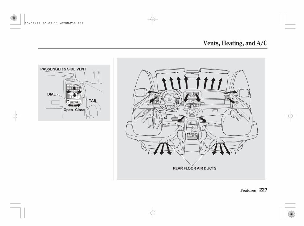
Vents, Heating, and A/C
Features 227
PASSENGER’S SIDE VENT
Open Close
DIAL
TAB
REAR FLOOR AIR DUCTS
10/09/29 20:09:11 42SWAF30_232
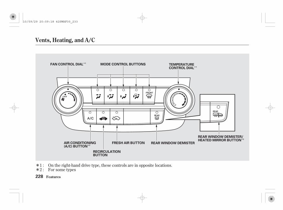
*
*
*
*
** For some types
On the right-hand drive type, these controls are in opposite locations.1 :2 :
Vents, Heating, and A/C
Features228
RECIRCULATIONBUTTON
FRESH AIR BUTTON
MODE CONTROL BUTTONS TEMPERATURECONTROL DIAL
FAN CONTROL DIAL
REAR WINDOW DEMISTER
REAR WINDOW DEMISTER/HEATED MIRROR BUTTON
AIR CONDITIONING(A/C) BUTTON
1
1
2
2
10/09/29 20:09:18 42SWAF30_233

Turn the dial clockwise to increasethe fan speed and airflow. Turn thedial anticlockwise to decrease them.
Turning this dial clockwise increasesthe temperature of the airflow.
These two buttons control thesource of air going into the system.In fresh air mode , air comesfrom outside the vehicle. Inrecirculation mode , theinterior air recycles through thesystem.
The outside air intakes for theheating and cooling system are atthe base of the windscreen. Keepthis area clear of leaves and otherdebris.
The system should be left in freshair mode under almost all conditions.Keeping the system in recirculationmode, particularly with the A/C off,can cause the windows to fog up.
Switch to recirculation mode whendriving through dusty or smokyconditions, then return to fresh airmode.
On some models, this button alsooperates the heated outside mirrors(see page ).
This button turns the rear windowdemister off and on (see page ).
This button turns the airconditioning on and off. Theindicator in the button is on whenthe A/C is on.
156
211
If equipped
Vents, Heating, and A/C
Features
Air Conditioning (A/C) ButtonFan Control Dial
Temperature Control Dial
Fresh Air and RecirculationButtons
Rear Window DemisterButton
229
10/09/29 20:09:36 42SWAF30_234

Air flows from the centreand corner vents in the dashboard.
Airflow is divided betweenthe vents in the dashboard and thefloor vents.
Air flows from the floorvents.
Airflow is divided betweenthe floor vents and demister vents atthe base of the windscreen.
Air flows from the demistervents at the base of the windscreen.
The flow-through ventilation systemdraws in outside air, circulates itthrough the interior, then dischargesit through vents near the tailgate.
Set the temperature to the lowerlimit.Make sure the A/C is off.Select and fresh air mode.Set the fan to the desired speed.
Use the mode control buttons toselect the vents air flows from. Someair will flow from the dashboardcorner vents in all modes.
When you select or ,the system automatically switches tofresh air mode and turns on the A/C.
1.
2.3.4.
Vents, Heating, and A/C
Features
Mode Control Ventilation
230
10/09/29 20:09:52 42SWAF30_235

The heater uses engine coolant towarm the air. If the engine is cold, itwill be several minutes before youfeel warm air coming from thesystem.
Select and fresh air mode.Set the fan to the desired speed.Adjust the warmth of the air withthe temperature control dial.
Your vehicle has the hot gas heatersystem. It assists the heater to warmthe air (see page ).
If the interior is very warm, you cancool it down more rapidly by partiallyopening the windows, turning on theA/C, and setting the fan tomaximum speed in fresh air mode.
Air conditioning places an extra loadon the engine. Watch the enginecoolant temperature gauge (see page
). If it moves near the red zone,turn off the A/C until the gaugereading returns to normal.
Turn on the A/C by pressing thebutton. The indicator in the buttoncomes on when a fan speed isselected.Make sure the temperature is setto maximum cool.Select .If the outside air is humid, selectrecirculation mode. If the outsideair is dry, select fresh air mode.Set the fan to the desired speed.
Air conditioning, as it cools, removesmoisture from the air. When used incombination with the heater, itmakes the interior warm and dry andcan prevent the windows fromfogging up.
Turn the fan on.Turn on the air conditioning.Select and fresh air mode.Adjust the temperature to yourpreference.
This setting is suitable for all drivingconditions whenever the outsidetemperature is above 0°C.
1.2.3.4.
1.
2.
3.4.
5.
100
1.2.3.
242
On vehicles with air conditioning system On vehicles with air conditioning system
Features
Using the Heater Dehumidify the InteriorUsing the A/C
Vents, Heating, and A/C
On Diesel models only
231
10/09/29 20:10:09 42SWAF30_236

To remove fog from the inside of thewindows:
Turning the fan speed control dial allthe way to the left shuts the systemoff.
Keep the system off for shortperiods only.
To keep stale air and mustinessfrom collecting, you should havethe fan running at all times.
When you switch to another modefrom , the A/C stays on.Press the A/C button to turn it off.
Select and fresh air mode.On some types, the systemautomatically switches to fresh airmode and turns on the A/C.Select .Set the fan and temperaturecontrols to maximum level.
For your safety, make sure you havea clear view through all the windowsbefore driving.
Set the fan to the desired speed orhigh for faster defrosting.Turn on the air conditioning.Select and fresh air mode.On some types, when you select
, the system automaticallyswitches to fresh air mode andturns on the A/C .Adjust the temperature so theairflow feels warm.Select to help clear therear window.To increase airflow to thewindscreen, close the side vents.
To clear the windows faster, you canclose the dashboard corner vents byrotating the wheel below it. This willsend more warm air to thewindscreen defroster vents. Oncethe windscreen is clear, select thefresh air mode to avoid fogging thewindows.
1.
2.3.
4.
5.
6.
1.
2.3.
On some types
Vents, Heating, and A/C
Features
To Defog and Defrost To Remove Exterior Frost or IceFrom the Windows
To Turn Everything Off
232
10/09/29 20:10:25 42SWAF30_237

On vehicles with air conditioning system
To activate the climate controlsystem, the engine must be running.
The direction of airflow from thevents in the centre and each cornerof the dashboard is adjustable.
To adjust the airflow from each vent,move the tab in the centre of eachvent up-and-down and side-to-side.
The vents in the corners of thedashboard can be opened and closedwith the dials underneath them.
The automatic climate controlsystem in your vehicle maintains theinterior temperature you select,removes moisture from the air andmakes the interior dry. The systemalso adjusts the fan speed andairflow levels.
In the AUTO mode, the vehicle’sinterior temperature isindependently regulated for thedriver and passenger.
You can adjust the temperatures ofthe driver’s side and the passenger’sside independently (see page ).240
CONTINUED
Climate Control System
Features 233
CENTRE VENTS
DIAL
OpenClose
DRIVER’S SIDE VENT TABTABS
10/09/29 20:10:39 42SWAF30_238

On vehicles with navigation systemIn addition to the standard airconditioning controls, the climatecontrol system in your vehicle can beoperated using the voice controlsystem. See the navigation systemmanual for complete details.
Climate Control System
Features
Voice Control System
234
PASSENGER’S SIDE VENT
Open
DIAL
TAB
REAR FLOOR AIR DUCTS
Close
10/09/29 20:10:48 42SWAF30_239

*
* *
On the right-hand drive type, these controls are in opposite locations.:
Climate Control System
Features 235
RECIRCULATIONBUTTON
MODE BUTTON
AUTOBUTTON
OFFBUTTON
AIR CONDITIONINGBUTTON
DUALBUTTON
FANCONTROLBAR
DRIVER’S SIDETEMPERATURECONTROL DIAL
WINDSCREENDEMISTERBUTTON
PASSENGER’S SIDETEMPERATURECONTROL DIAL
REAR WINDOW DEMISTER/HEATED MIRROR BUTTON
10/09/29 20:10:55 42SWAF30_240

To put the automatic climate controlin fully-automatic mode:
Press the AUTO button.
Set the desired temperature byturning the driver’s sidetemperature control dial. You willsee AUTO and the selectedtemperature in the display. Youcan also set the passenger’s sidetemperature by turning thepassenger’s side dial.
The system automatically selects theproper mix of conditioned and/orheated air that will, as quickly aspossible, raise or lower the interiortemperature to your preference.
Your vehicle has the hot gas heatersystem. It assists the heater to warmthe air (see page ).
You can set the temperatures for thedriver’s side and the passenger’s sideseparately when this button ispressed (indicator is on). When theindicator in the DUAL button is off,the temperatures for both sides aresynchronized to the driver’s side settemperature. When defrost mode isselected, dual mode operation iscancelled.
When the indicator in the dualbutton is on, the driver’s side andpassenger’s side temperature can becontrolled independently (see page
).
The driver’s side temperature andthe passenger’s side temperature canbe set separately. Turn the dial ofthe appropriate temperature controlclockwise to increase thetemperature of airflow. Turn the dialanticlockwise to decrease it. Each settemperature is shown in the display.
In cold weather, the fan will notcome on automatically until theheater starts to develop warm air.
When you set the temperature to itslower limit ( ) or its upper limit( ), the system runs at fullcooling or heating only. It does notregulate the interior temperature.
When you adjust a fan control, thefan is taken out of AUTO mode.
1.
2.
240
242
Automatic Climate Control
Climate Control System
Features
On Diesel models only
Dual Button
Temperature Control
236
10/09/29 20:11:11 42SWAF30_241

When the recirculation indicator ison, air from the vehicle’s interior issent throughout the system again.When the indicator is off, air isbrought in from the outside of thevehicle (fresh air mode).
The outside air intakes for theclimate control system are at thebase of the windscreen. Keep thisarea clear of leaves and other debris.
The system should be left in freshair mode under almost all conditions.Keeping the system in recirculationmode, particularly with the A/C off,can cause the windows to fog up.
Switch to recirculation mode whendriving through dusty or smokyconditions, then return to fresh airmode.
You can manually select variousfunctions of the climate controlsystem when it is in fully-automaticmode. All other features remainautomatically controlled. Making anymanual selection causes the wordAUTO in the display to go out.
Press the A/C button to turn the airconditioning on and off. You will seeA/C ON or A/C OFF in the display.
When you turn the A/C off, thesystem cannot regulate the insidetemperature if you set thetemperature control dial below theoutside temperature.
If you press the OFF button, theclimate control system shuts offcompletely.
Keep the system completely offfor short periods only.
To keep stale air and mustinessfrom collecting, you should havethe fan running at all times.
CONTINUED
Climate Control System
Features
Recirculation Button
Air Conditioning (A/C) Button
To Turn Everything Off Semi-automatic Operation
237
10/09/29 20:11:26 42SWAF30_242

▲ ▼
Select the fan speed by pressingeither side of the fan speed controlbar ( or ). The fan speed isshown in vertical bars on the display.
Use the MODE button to select thevents the air flows from. Some airwill flow from the dashboard cornervents in all modes.
Each time you press the MODEbutton, the display shows the modeselected.
Airflow is divided betweenthe floor and corner vents, and thedemister vents at the base of thewindscreen.
Air flows from the floor andcorner vents.
Airflow is divided betweenthe vents in the dashboard and thefloor vents.
Air flows from the centreand corner vents in the dashboard.
Climate Control System
Features
Fan Control Mode Button
238
10/09/29 20:11:39 42SWAF30_243

This button directs the main airflowto the windscreen for fasterdefrosting. It also overrides anymode selection you may have made.
When you select , the systemautomatically switches to fresh airmode and turns on the A/C. Forfaster defrosting, manually set thefan speed to high. You can alsoincrease airflow to the windscreenby closing the corner vents on thedashboard.
When you turn off bypressing the button again, thesystem returns to its former settings.
This button turns the rear windowdemister off and on (see page ).
To remove fog from the inside of thewindows, set as follows:
For your safety, make sure you havea clear view through all the windowsbefore driving.
When the indicator in the button ison, the front passenger’stemperature cannot be set separatelyfrom the driver’s.
Select . The systemautomatically switches to fresh airmode and turns on the A/C.Adjust the temperature with thedriver’s side temperature controlso the airflow feels warm.Select to help clear therear window.To increase airflow to thewindscreen, close the corner vents.For faster defogging, manually setthe fan speed to high.
Pushing this button also turns thepower mirror heaters on and off.
1.
2.
3.
4.
156
Windscreen Demister Button Rear Window Demister Button
Climate Control System
Features 239
10/09/29 20:11:54 42SWAF30_244

The temperatures of the driver’s sideand the passenger’s side can becontrolled independently when theindicator in the DUAL button is on.
To adjust the driver’s side, turn thedriver’s side temperature control dialon the climate control panel. Toadjust the passenger’s side, turn thepassenger’s side temperature controldial.
Push AUTO or . The selectedtemperatures appear in the display.When the indicator in the DUALbutton is off, you can adjust bothsides to the same temperature byadjusting the driver’s temperaturecontrol dial.
Dual Temperature Control
Climate Control System
Features240
Driver’s Side Passenger’s Side
10/09/29 20:12:03 42SWAF30_245

To set the driver’s side temperatureto a different value than thepassenger’s side, press the DUALbutton, then turn the temperaturecontrol dial on the control panel. Toset the passenger’s side to adifferent value than the driver’s side,turn the passenger’s sidetemperature control dial. You canadjust the passenger’s side withoutpressing the DUAL button first.
When you set the temperature to itslower limit or its upper limit, it will bedisplayed as ‘‘ ’’ or ‘‘ ’’.
The climate control system has twosensors: a sunlight sensor on top ofthe dashboard, and a temperaturesensor next to the steering column.Do not cover the sensors or spill anyliquid on them.
Climate Control System
Features
Sunlight and TemperatureSensors
241
SUNLIGHT SENSOR
TEMPERATURE SENSOR
10/09/29 20:12:12 42SWAF30_246

-
Your vehicle has the hot gas heatersystem. It assists the heater until theengine warms up after you start theengine. This system uses yourvehicle’s air conditioning system towarm the air. Under the followingconditions, the hot gas heatersystem operates automatically.
The engine coolant is cold (underabout 75°C).
The outside temperature is low(under about 5°C).
Any temperature except for themaximum cool can be set with thedriver’s side temperature controldial.
After the engine warms up or theoutside temperature is high, the hotgas heater system will stopautomatically.
You may hear some noise from theengine compartment. This is normal;it is the hot gas heater activation.
The hot gas heater system will notactivate if the outside temperature istoo cold (under 35°C).
The fan is set to the desired speed.
On Diesel models only
Climate Control System
Hot Gas Heater System
Features242
10/09/29 20:12:23 42SWAF30_247

The audio system is standardequipment on some models. Thissection explains how to operate thestandard audio system installed onvehicles without navigation system.Refer to the navigation systemowner’s manual for information ofhow to operate the audio system onthe vehicle with navigation system.The anti-theft feature may disablethe system if it is disconnected fromthe vehicle’s battery. To get thesystem working again, you mustenter a code number (see page ).
This product conforms to DM 28/8/1995, N. 548, by complying with therequirements specified in DM 25/6/1985 (par. 3, All. A) and DM 27/8/1987 (All. I).
291
For some EU countries
Audio System
Features 243
Audio System with In-dash Disc Changer
Audio System with In-dash Disc Player
Without navigation system
10/09/29 20:12:34 42SWAF30_248

On vehicles with navigation systemIn addition to the standard audiocontrols, the audio system in yourvehicle can be operated using thevoice control system. See thenavigation system manual forcomplete details.
Audio System
Features
Voice Control System
244
With navigation system
10/09/29 20:12:41 42SWAF30_249

Playing the Radio
Features 245
FMBUTTON
BUTTON BUTTON
BUTTON
BUTTON
VOL/SELECT KNOB
A.SELBUTTON
SCANBUTTON
PRESET BUTTONS
SEEK BUTTON SEEK BUTTON
PRESET BUTTONS
BUTTON
BUTTON
PRESET BUTTONS
SEEK BUTTON SEEK BUTTON
AM BUTTON
PRESET BUTTONS
FMBUTTON
SCANBUTTON
A.SELBUTTON
VOL/SELECT KNOB
AM BUTTON
Audio System with In-dash Disc Changer Audio System with In-dash Disc Player
10/09/29 20:12:56 42SWAF30_250

- -
-
The ignition switch must be in theACCESSORY (I) or ON (II) position.Turn the system on by pushing theFM or AM button. Adjust the volumeby turning the VOL/SELECT knob.
On the AM band, AM noisereduction turns on automatically.
Use the SEEK button totune to a desired frequency. Pressthe button to tune to a higherfrequency, and the button totune to a lower frequency.
You can also use the select buttonand VOL knob to tune the radio to adesired frequency. Push the selectbutton. You will see ‘‘ ’’ in thedisplay. Turn the VOL knobclockwise to tune to a higherfrequency, or anticlockwise to tuneto a lower frequency.
The mode will be cancelled about 10seconds after you stop adjusting theknob. If you want to cancel the modewithin 10 seconds, push the selectbutton, ( ) button, or ( )button.
The SEEK functionsearches up and down from thecurrent frequency to find a stationwith a strong signal. To activate it,press and hold the or
button until you hear a beep.
The scan function samplesall stations with strong signals on theselected band. To activate it, pressthe SCAN button, then release it.You will see SCAN in the display.When the system finds a strongsignal, it will stop and play thatstation for about 10 seconds.
If you do nothing, the system willscan for the next strong station andplay it for 10 seconds. When it playsa station that you want to listen to,press the SCAN button again.
You can use any of five methods tofind radio stations on the selectedband: tune, seek, scan, the presetbuttons, and auto select.
The band and frequency that theradio was last tuned to are displayed.To change bands, press the AM orFM button. On the FM band, ST willbe displayed if the station isbroadcasting in stereo. Stereoreproduction in AM is not available.
To Play the Radio TUNE SEEK
SCAN
To Select a Station
Playing the Radio
Features246
10/09/29 20:13:14 42SWAF30_251

-
-
-Each preset button canstore one frequency on AM and twofrequencies on FM.
Select the desired band, AM orFM.
Use the tune, seek, or scanfunction to tune the radio to adesired station.
Pick the preset number (1 6),and hold it until you hear a beep.
Repeat steps 1 through 3 to store atotal of six stations on AM andtwelve stations on FM.
If you aretravelling and can no longer receiveyour preset stations, you can use theauto select feature to find stations inthe local area.
Press the A. SEL button. You will seeA. SEL flashing in the display, andthe system goes into scan mode forseveral seconds. The system storesthe frequencies of 6 FM stations inthe preset buttons.
You will see a ‘‘0’’ displayed afterpressing a preset button if autoselect cannot find a strong station forevery preset button.
If you do not like the stations autoselect has stored, you can storeother frequencies on the presetbuttons as previously described.
press theA. SEL button. This restores thepresets you originally set.
1.
2.
3.
4.
To turn off auto select,
Preset AUTO SELECT
Playing the Radio
Features 247
10/09/29 20:13:26 42SWAF30_252

-
-
-
-
-
Alternative frequency function on oroff
Regional programme on or off
Programme service function on oroff
News programme on or off
Automatic traffic programme on oroff
With your audio system, you canutilize many convenient featuresprovided by the radio data system(RDS).
With the FM band selected, you cankeep listening to the same stationeven if its frequency changes as youenter different regions while you aretravelling.
The RDS function turns onautomatically when you turn thesystem on. If the station you arelistening to is an RDS station, thefrequency display will change to thestation name. Then, the system willautomatically keep selecting thefrequency with the strongest signalfrom the frequencies that carry thesame programmes. This can saveyou the trouble of retuning to obtainthe same station as long as you are inthe same RDS network area.
You can turn on or off the RDSfunction and select the RDSprogrammes. To switch the functionand select the programme, press the
button for more than 2 secondswith the audio system on. You willhear a beep. Press any of the presetbuttons (1 through 6) to select thefunction. Each preset button has thefollowing function. Pressing thepreset button switches the functionbetween on and off (24H and 12H onthe clock mode).
Radio Data System (RDS) Preset 1: AF ON/OFF
Preset 2: REG ON/OFF
Preset 3: PS DISP ON/OFF
Preset 5: NEWS ON/OFF
Preset 4: AUTO TP ON/OFF
Preset 6: CLOCK 24H/12H
Playing the Radio
Features248
10/09/29 20:13:39 42SWAF30_253

- -
-
-
-
-
This function automatically selects afrequency with the same programmein the RDS network area.
With this function, youcan switch the clock display between24-hours and 12-hours.
When the signals of the RDS stationbecome so weak that the system canno longer follow the station, thesystem will hold the last tunedfrequency and the display willchange from the station name to thefrequency.
In some countries, you cannot utilizefeatures provided by RDS as theRDS function is not provided for allstations.
Thisfunction automatically tunes to theradio station which is broadcastingnewscasts.
Thisfunction automatically tunes to theradio station which is broadcastingthe traffic information.
This function shows theradio station name which you arelistening to.
To turn on the RDS, select 1 AF ONby pressing the preset 1. To turn offthe RDS, select 1 AF OFF. Press the
button again to store thesetting.
This function keepsthe regional programme and doesnot change the frequency even if thesignal becomes too weak.
CONTINUED
AF (Alternative Frequency) CLOCK
NEWS (News Programme)
AUTO TP (Automatic TrafficInformation Programme)
PS DISP (Programme ServiceDisplay)
REGIONAL (RegionalProgramme)
Playing the Radio
Features 249
10/09/29 20:13:51 42SWAF30_254

When the automatic trafficinformation programme (AUTO TPON) is selected, TP will come on inthe display. This indicates that thetraffic reports can be received fromthe traffic information broadcastingstation.
AUTO TP cross-references otherprogramme services that broadcasttraffic information, and the trafficreports can be received throughanother programme service in theRDS network area.
When you press and release the TAbutton, TA comes on in the displayand the system stands by for trafficannouncements.
If the station you are listening to isan RDS station, the frequencydisplay will disappear and the stationname or PTY information will bedisplayed. For more information onthe PTY, see page .
You can receive traffic informationwhile you are listening to a disc orplaying an appropriate audio device.If the system is tuned to a TP stationbefore playing a disc or an audiodevice, the system will stand by fortraffic announcements with the TAbutton pressed (TA indicator is on)and the system will switch from discor AUX mode to the trafficannouncement when it begins. Youwill see TA-INFO in the display. Thesystem will return to the disc or AUXmode when the traffic information isfinished.
You can also switch to the normalaudio mode while you are listening tothe traffic information by pressingthe TA button. It does not cancel theTA standby function.
251
Programme Service Name Display TA (Traffic Announcement) StandbyFunction
Playing the Radio
Features250
10/09/29 20:14:01 42SWAF30_255

If your vehicle’s battery goes dead,or is disconnected, the trafficannouncement volume level will bereset to the default setting (level 9).
If you use seek or auto select withthe TA function on, the systemsearches only TP stations.
To turn off the TA function, pressthe TA button again. TA will go outfrom the display.
Pressing the TA button will not turnoff the TA function while you arelistening to the traffic information. Itwill just switch to the selected audioplaying mode.
When either of the or thebutton is pressed, the display
shows you the programme type ofthe selected RDS station. Forexample, if the station isbroadcasting drama, DRAMA isshown in the display. If it is a stationof scientific programmes, SCIENCEis shown. The principal PTYs areshown as follows.
NEWS: Short accounts of facts,events, publicly expressed views,reportage, etc.CURRENT AFFAIRS: Topicalprogrammes expanding upon thenews.
To adjust the volume of the trafficannouncement, turn the VOL/SELECT knob while theannouncement is broadcasting. Theadjusted volume level will be stored,then that level will be used on thenext traffic announcement. If youadjust the volume below theminimum level, the default level(level 9) will be used the next time.The volume of the PTY NEWS orthe PTY ALARM function can alsobe adjusted (see page ).254
CONTINUED
PTY (Programme Type) DisplayFunction
Playing the Radio
Features 251
10/09/29 20:14:13 42SWAF30_256
INFORMATION: Generalinformation and advice.SPORT: Programmes concernedwith any aspect of sports.EDUCATION: Educationalprogrammes.DRAMA: All radio plays and serials.
SCIENCE: Programmes aboutnature, science, and technology.
POP MUSIC: Commercial music ofpopular appeal.ROCK MUSIC: Contemporarymodern music.
VARIED SPEECH: Lightentertainment programmes.
EASY LISTENING: Light music.
LIGHT CLASSICS M: Light classics;classical music for non-specialistappreciation.SERIOUS CLASSICS: Traditionalclassics.
CHILDREN’S PROGS: Programmesfor children.
FINANCE: Programmes concernedwith economy.
WEATHER/METR: Weatherinformation.
OTHER MUSIC: Other types ofmusic, such as R & B, Reggae.
CULTURE: Programmes concernedwith any aspect of national orregional culture.
RELIGION: Programmes concernedwith religion.SOCIAL AFFAIRS: Social affairsprogrammes.
PHONE IN: Programmes consistingof listener’s message.TRAVEL/TOURING: Programmesconcerned with travel.LEISURE/HOBBY: Programmesabout hobbies and recreationalactivities.JAZZ MUSIC: Jazz music.COUNTRY MUSIC: Country music.NATION MUSIC: National music.OLDIES M: Oldies music, ‘‘Goldenage’’ based programmes.FOLK MUSIC: Folk music.DOCUMENTARY: Documentaryprogrammes.
Playing the Radio
Features252
10/09/29 20:14:36 42SWAF30_257

If the selected RDS station does nottransmit PTY data, NO PTY isdisplayed. When the selected stationis not an RDS station, NO RDS isdisplayed for about 5 seconds.
Some stations may broadcast theprogrammes with different contentsfrom their PTY code.
When you press either of thebutton or button, the
display will show different PTYs (seethe PTYs list on the previous page).
The PTY setting mode is cancelled ifno further steps are taken within 5seconds after selecting the desiredPTY with the or button.
After you select the desiredprogramme type, the system willsearch for a station with the samePTY code as the selectedprogramme type. When you use thisfunction for the first time, NEWSwill appear as it was preset at thefactory.
After your desired PTY is displayed,press either TUNE/SEEK button( or ) within 5 seconds.The system will go into the PTYsearch mode and search for a stationof the selected PTY. If there is nostation available in the selected PTY,NO PTY is displayed for about 5seconds and the PTY search mode iscancelled.
To activate this function, press thebutton for more than 2 seconds
and select NEWS. The system willhold the last tuned FM station/network PTY while you are listeningto the disc. With this function on,playing disc or an appropriate audiodevice is interrupted and the systemswitches from disc, AUX or USBmode to the FM newscast when thenewscast is broadcasting from theFM station.
When the programme is changed toanother programme or thefrequency cannot be received for 10seconds due to a weak signal, thesystem will return to the disc modeautomatically.
You can change the volume level ofthe interrupted newscast. Refer topage for how to adjust thevolume level.
251
CONTINUED
PTY/News Interrupt Function
Playing the Radio
Features 253
10/09/29 20:14:51 42SWAF30_258

Your audio system has anotherinterrupt function (including TAfunction). The first activatedinterrupt function has priority overthe others and the indication of theother interrupt function goes out. Toactivate the other interrupt function,turn off the current interruptfunction.
PTY code ‘‘ALARM’’ is used foremergency announcements, such asnatural disasters. When this code isreceived, ‘‘ALARM’’ comes on thedisplay and the volume is changed.When the alarm is cancelled, thesystem will return to the normaloperation mode.
PTY Alarm
Playing the Radio
Features254
10/09/29 20:14:57 42SWAF30_259

-
-
-
-
-
-
Adjusts the volume levelbased on the vehicle speed.
The SVC has four modes: SVC OFF,SVC LOW, SVC MID, and SVCHIGH. Turn the VOL/SELECT knobto adjust the setting to your liking. Ifyou feel the sound is too loud,choose low. If you feel the sound istoo quiet, choose high.
Each mode is shown in the display asit changes. Turn the VOL/SELECTknob to adjust the setting to yourliking.
The SVC mode controls the volumebased on vehicle speed. The fasteryou go, the louder the audio volumebecomes. As you slow down, theaudio volume decreases.
The system will return to the audiodisplay about 10 seconds after youstop adjusting a mode.
When the level reaches centre, youwill see a ‘‘C’’ in the display. Eachtime the level reaches maximum,minimum or centre, you will hear abeep.
Press the sound ( ) button toselect an appropriate setting: bass,treble, fader, balance, subwoofer (ifequipped), and SVC (speed-sensitivevolume compensation). Turn theVOL/SELECT knob to adjust thesetting.
Adjusts the bass.
Adjusts the treble.
Adjusts the front-to-backstrength of the sound.
Adjusts the balance,or side-to-side strength of the sound.
Adjusts thestrength of sound from thesubwoofer speaker.
You can use the instrument panelbrightness control knob to adjust theillumination of the audio system (seepage ). The audio systemilluminates when the position lightsare on, even if the radio is turned off.
155
Except for SVC
SVC
BASS
TREBLE
FADER
BALANCE
SUBWOOFER
Audio System Lighting
Speed-sensitive VolumeCompensation (SVC)
(If equipped)
Features
Adjusting the Sound
255
10/09/29 20:15:14 42SWAF30_260
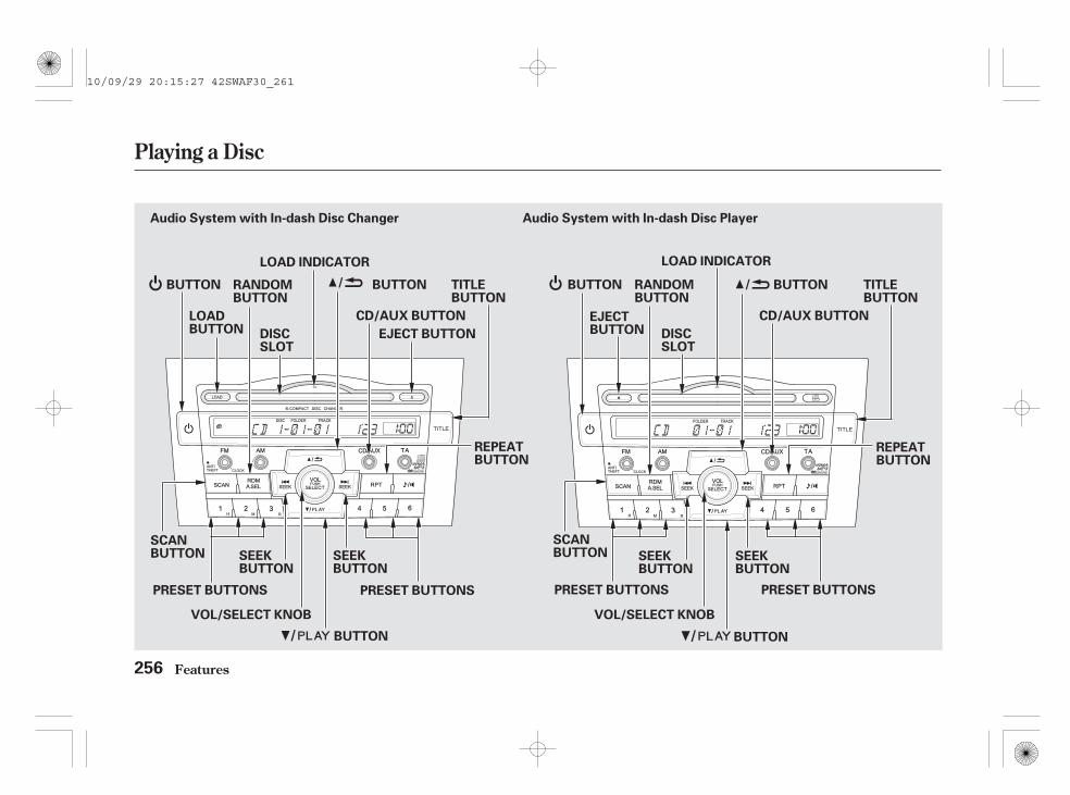
Playing a Disc
Features256
RANDOMBUTTON
TITLEBUTTON
BUTTON BUTTON
EJECT BUTTON
LOAD INDICATOR
DISCSLOT
LOADBUTTON
REPEATBUTTON
SEEKBUTTON
SEEKBUTTON
SCANBUTTON
RANDOMBUTTON
BUTTON
LOAD INDICATOR
DISCSLOT
REPEATBUTTON
SEEKBUTTON
SCANBUTTON SEEK
BUTTON
EJECTBUTTON
PRESET BUTTONSPRESET BUTTONS
VOL/SELECT KNOB
PRESET BUTTONS
BUTTON
VOL/SELECT KNOB
BUTTON
TITLEBUTTON
BUTTON
PRESET BUTTONS
Audio System with In-dash Disc Changer Audio System with In-dash Disc Player
CD/AUX BUTTON CD/AUX BUTTON
10/09/29 20:15:27 42SWAF30_261

To load or play discs, the ignitionswitch must be in the ACCESSORY(I) or ON (II) position.
Do not use discs with adhesive labels.The label can curl up and cause thedisc to jam in the unit.
When there are more than 99 foldersin a disc, the audio display onlyshows two digits.
This audio system can also playCD-Rs and CD-RWs compressed inMP3 or WMA formats. The numbersof the folder and track playing areshown in the display on the discplayer. A disc can support up to 255folders, and each folder can hold upto 255 playable files. A disc can holdup to 999 files in total.
You operate the disc player/changerwith the same controls used for theradio. To select the disc player/changer, press the CD/AUX button.The number of the track playing andthe elapsed time are shown in thedisplay. On the in-dash disc changer,the disc number is also displayed.You can also select the displayedinformation with the TITLE button(see page ). The system willcontinuously play a disc until youchange modes.
Video CDs and DVDs do not work inthis unit.260
CONTINUED
To Play a Disc
Playing a Disc
Features 257
10/09/29 20:15:37 42SWAF30_262

Depending on the software the fileswere made with, it may not bepossible to play some files, or displaysome text data.
If a file on a WMA disc is protectedby digital rights management(DRM), the audio unit displaysUNSUPPORTED, and then skips tothe next file.
Playing a Disc
Features258
NOTE:
10/09/29 20:15:42 42SWAF30_263

You cannot load and play 8-cm(3-inch) discs in this unit.
When the disc load indicator turnsgreen and ‘‘LOAD’’ appears in thedisplay again, insert the next discin the slot. Do not try to insert adisc until ‘‘LOAD’’ appears. Youcould damage the audio unit.
Repeat this until all six positionsare loaded. If you are not loadingall six positions, the system beginsreading and playing the last discloaded.
You can also load a disc into anempty position while a disc is playingby pressing the appropriate side ofthe preset button. The system stopsplaying the current disc and startsthe loading sequence. It plays thedisc just loaded.
Your vehicle’s in-dash disc changerholds up to six discs.
Press the LOAD button until youhear a beep and see ‘‘LOAD’’ inthe display. To load only one disc,press and release the LOADbutton. The green disc loadindicator will come on.
The disc number for an emptyposition begins blinking.
Insert a disc about halfway into thedisc slot. The drive will pull the discin the rest of the way and begin toplay it. The number of the trackplaying is shown in the display. Thesystem will continuously play a discuntil you change modes.
You cannot load and play 8-cm(3-inch) discs in this unit.
Insert the disc into the disc slotwhen the green disc load indicatorcomes on. Insert it only abouthalfway; the drive will pull it in therest of the way. You will see ‘‘DISCREAD’’ in the display while thedisc load indicator turns red andblinks as the disc is loaded.
1.
2.
3.
4.
5.
CONTINUED
To Load a DiscIn-dash Disc Player
In-dash Disc Changer
Playing a Disc
Features 259
10/09/29 20:15:55 42SWAF30_264

>
The display shows up to 16characters of selected text data (thefolder name, file name, etc.).
If the text data has more than 16characters, you will see the first 15characters and the indicator onthe display. Press and hold theTITLE button until the next 16characters are shown. You can seeup to 31 characters of text data.
If you press and hold the TITLEbutton again, the display shows thefirst 15 characters again.
If any letter is not available, it isreplaced with ‘‘ . ’’ (dot) in the display.When the disc has no text data, youwill see ‘‘NO INFO’’ on the display.
Each time you press the TITLEbutton, the display shows you thetext, if the disc was recorded withtext data.
You can see the album, artist, andtrack name in the display. If a disc isrecorded in MP3 or WMA, you cansee the folder and file name, and thealbum, artist, and track tag.
Text Data Display Function
Playing a Disc
Features260
10/09/29 20:16:04 42SWAF30_265

-
You will also see some text dataunder these conditions:
When playing a CD-DA with textdata, the album and track name areshown in the display. With a disc inMP3 or WMA, the display shows thefolder and file name.
To select a different disc, use theappropriate preset buttons (1through 6). If you select an emptyposition, the system will go into theloading sequence (see page ).
When a new folder, file, or track isselected.
When you change the audio modeto play a disc with text data or inMP3 or WMA.
When you insert a disc, and thesystem begins to play.
You can use the SEEK buttons whilea disc is playing to select passagesand change tracks (files in MP3/WMA mode).
In MP3/WMA mode, use theor button to select
folders in the disc, and use the SEEKbutton to change files.
To select a different disc, press theappropriate preset button (1 6). Ifyou select an empty position in thedisc changer, the system will try toload the disc in the next availableslot.
259
CONTINUED
In-dash Disc Changer
In-dash Disc Changer
To Change or Select Tracks/Files
Playing a Disc
Features 261
10/09/29 20:16:17 42SWAF30_266

--- In MP3 or WMA mode
To continuously replaya track (file in MP3/WMA mode),press and release the RPT button.You will see RPT in the display.Press and hold the RPT button toturn it off.
Toselect a different folder, press the
or button. Press thebutton to skip to the next
folder, and the button to skipto the previous folder.
Each time you press andrelease the button, the playerskips forward to the beginning of thenext track (file in MP3 or WMAmode). Press and release the
button to skip backward to thebeginning of the current track. Pressit again to skip to the beginning ofthe previous track.
To move rapidly within a track, pressand hold the , or the
button.
You can also operate the trackselection by using the VOL/SELECTknob. Press the VOL/SELECT knoband you will see ‘‘SEL’’ in the display.Turn the knob to switch the tracknumber. Press the VOL/SELECTknob or button to set yourselection. To turn it off, press the
button.
You can also operate the folder andfile selection by using the VOL/SELECT knob. Press the VOL/SELECT knob and you will see SELin the display. Turn the knob toswitch the folder number and pressthe knob to set your selection. Turnthe same knob to switch a file, thenpress it to set your selection. Tocancel the selection, press the
button.
REPEAT (TRACK/FILEREPEAT)FOLDER SELECTION
SEEK
Playing a Disc
Features262
10/09/29 20:16:34 42SWAF30_267

- - -In MP3 or WMA mode In-dash Disc Changer
In-dash Disc Player
This feature,when activated, replays all the filesin the selected folder in the orderthey are compressed in MP3/WMA.To activate folder repeat mode, pressthe RPT button repeatedly until yousee F-RPT in the display. The systemcontinuously replays the currentfolder. Press and hold the RPTbutton to turn it off.
To continuouslyreplay the current disc, press andrelease the RPT button repeatedlyuntil you see D-RPT in the display.Press and hold the RPT button for 2seconds again to turn it off.
Each time you press and release theRPT button, the mode changes fromfile repeat to folder repeat, to discrepeat then to normal play.
This feature plays thetracks within a disc in random order.In MP3/WMA mode, all files in allfolders are played in random order.To activate random mode, press theRDM button repeatedly until you seeRDM in the display. Press and holdthe RDM button to turn it off.
Each time you press and release theRPT button, the mode changes fromfile repeat to folder repeat, then tonormal play.
CONTINUED
FOLDER-REPEAT DISC-REPEATRANDOM (Random within adisc)
Playing a Disc
Features 263
10/09/29 20:16:44 42SWAF30_268

-- -
In MP3 or WMA mode In MP3 or WMA mode
In-dash Disc Player
The SCAN functionsamples all the tracks on the disc inthe order they are recorded on thedisc (all files in the current folder inMP3 or WMA mode). To activate thescan feature, press and release theSCAN button. You will see ‘‘SCAN’’in the display. You will get a 10second sampling of each track/file inthe disc/folder. Press and hold theSCAN button to get out of scanmode and play the last track sampled.
Thisfeature, when activated, plays thefiles in the current folder in randomorder, rather than in the order theyare compressed in MP3/WMA. Toactivate folder random play, pressthe RDM button. You will seeF-RDM in the display. The systemwill then select and play filesrandomly. This continues until youdeactivate folder random play bypressing and holding the RDMbutton.
Each time you press and release theRDM button, the mode changesfrom folder random play, to within adisc random play, then to normalplay.
This feature,when activated, samples the first filein each folder on the disc in theorder they are recorded. To activatethe folder scan feature, press theSCAN button repeatedly. You willsee ‘‘F-SCAN’’ in the display. Thesystem will then play the first file inthe main folders for about 10seconds. When it plays a file that youwant to continue listening to, pressand hold the SCAN button. Whenthe system samples the first file ofall folders, F-SCAN is cancelled, andthe system plays normally.
Each time you press and release theSCAN button, the mode changesfrom file scan to folder scan, then tonormal play.
SCANFOLDER-RANDOM FOLDER-SCAN
Playing a Disc
Features264
10/09/29 20:16:52 42SWAF30_269

- This functionsamples the first track of each discin the in-dash disc changer in theorder they are stored. To activatedisc scan, press the SCAN buttonrepeatedly until you see D-SCAN inthe display. The system will thenplay the first track/file of the firstdisc for approximately 10 seconds.After playing the first track/file ofthe last disc, the system playsnormally.
Each time you press and release theSCAN button, the mode changesfrom file scan, folder scan, disc scan,then to normal play.
To play the radio when a disc isplaying, press the AM or FM button.Press the CD/AUX button again toswitch back to the disc player or discchanger.
To play an audio unit connected tothe auxiliary input jack when a disc isplaying, press the CD/AUX button.Press the CD/AUX button again toswitch back to the disc player or discchanger.
Press the eject button ( ) toremove the disc. If you eject the disc,but do not remove it from the slot,the system will automatically reloadthe disc after 10 seconds and put it inpause mode. To begin playing, pressthe CD/AUX button.
You can also eject the disc when theignition switch is off.
If you turn the system off while adisc is playing, either with the( ) button or by turning off theignition switch, the disc will stay inthe drive. When you turn the systemback on, the disc will begin playingwhere it left off.
You can also press the MODEbutton on the steering wheel tochange modes.
CONTINUED
In-dash Disc ChangerDISC-SCAN
To Stop Playing a Disc Removing a Disc from the Player
Playing a Disc
Features 265
10/09/29 20:17:05 42SWAF30_270

To remove a different disc from thechanger, first select it with theappropriate preset button. When thatdisc begins playing, press the ejectbutton. Continue pressing the ejectbutton to remove all the discs fromthe changer.
You can also eject discs when theignition switch is off. The disc thatwas last selected is ejected first.
To remove the disc currently in play,press the eject ( ) button. Whena disc is removed from a slot, thesystem automatically begins the loadsequence so you can load anotherdisc in that position. If you do notremove the disc from the changerwithin 10 seconds, the systemreturns to the previous mode (AM,FM or AUX). The disc will reloadinto the system and will remain therepaused.
An optional six disc changer isavailable for your vehicle. This discchanger uses the same controls usedfor the in-dash disc player/changeror the radio.
Load the desired discs in themagazine, and load the magazine inthe changer according to theinstructions that came with the unit.
To select the disc changer, press theCD/AUX button. The disc and tracknumbers will be displayed. To selecta different disc, use either or
button. To select the previousdisc, press the button, or the
button to select the next disc insequence.
If you select an empty slot in themagazine, the changer will searchfor the next available disc to load andplay.
Removing Discs from the In-dashDisc Changer
Playing a Disc
Features
Operating the Optional DiscChanger(Optional for some types)
266
10/09/29 20:17:19 42SWAF30_271
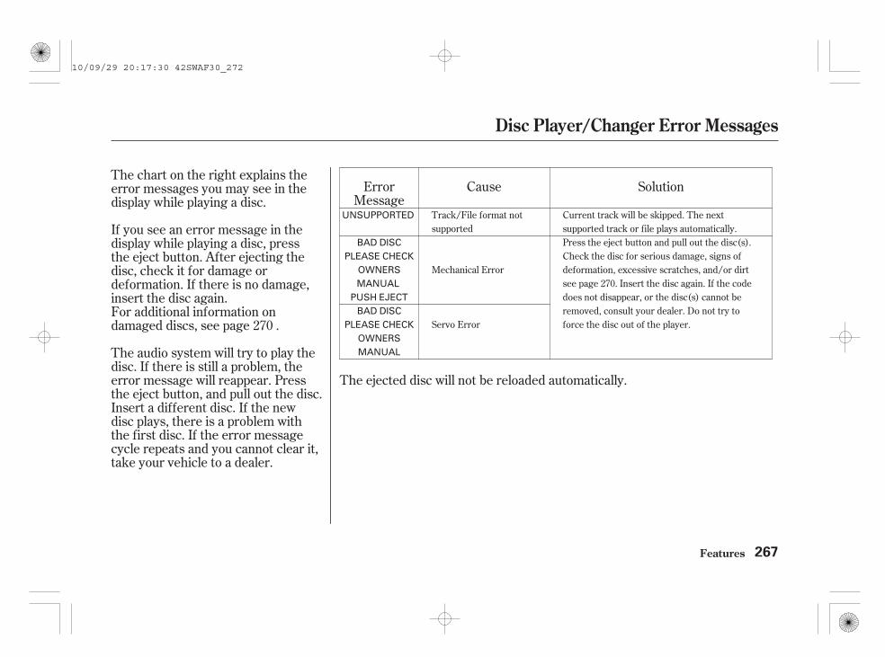
Cause
The ejected disc will not be reloaded automatically.
The chart on the right explains theerror messages you may see in thedisplay while playing a disc.
If you see an error message in thedisplay while playing a disc, pressthe eject button. After ejecting thedisc, check it for damage ordeformation. If there is no damage,insert the disc again.For additional information ondamaged discs, see page .
The audio system will try to play thedisc. If there is still a problem, theerror message will reappear. Pressthe eject button, and pull out the disc.Insert a different disc. If the newdisc plays, there is a problem withthe first disc. If the error messagecycle repeats and you cannot clear it,take your vehicle to a dealer.
SolutionErrorMessage
270
Track/File format notsupported
Mechanical Error
Servo Error
Current track will be skipped. The nextsupported track or file plays automatically.Press the eject button and pull out the disc(s).Check the disc for serious damage, signs ofdeformation, excessive scratches, and/or dirtsee page 270. Insert the disc again. If the codedoes not disappear, or the disc(s) cannot beremoved, consult your dealer. Do not try toforce the disc out of the player.
Disc Player/Changer Error Messages
Features 267
UNSUPPORTED
BAD DISCPLEASE CHECK
OWNERSMANUAL
PUSH EJECTBAD DISC
PLEASE CHECKOWNERSMANUAL
10/09/29 20:17:30 42SWAF30_272
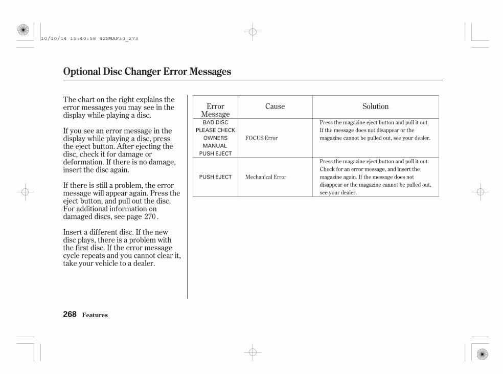
The chart on the right explains theerror messages you may see in thedisplay while playing a disc.
If you see an error message in thedisplay while playing a disc, pressthe eject button. After ejecting thedisc, check it for damage ordeformation. If there is no damage,insert the disc again.
If there is still a problem, the errormessage will appear again. Press theeject button, and pull out the disc.For additional information ondamaged discs, see page .
Insert a different disc. If the newdisc plays, there is a problem withthe first disc. If the error messagecycle repeats and you cannot clear it,take your vehicle to a dealer.
Cause SolutionErrorMessage
270
FOCUS Error
Mechanical Error
Press the magazine eject button and pull it out.If the message does not disappear or themagazine cannot be pulled out, see your dealer.
Press the magazine eject button and pull it out.Check for an error message, and insert themagazine again. If the message does notdisappear or the magazine cannot be pulled out,see your dealer.
Optional Disc Changer Error Messages
Features268
BAD DISCPLEASE CHECK
OWNERSMANUAL
PUSH EJECT
PUSH EJECT
10/10/14 15:40:58 42SWAF30_273

When using CD-R or CD-RW discs,use only high quality discs labelledfor audio use.
When recording a CD-R orCD-RW, the recording must beclosed for it to be used by thesystem.
Play only standard round discs.Odd-shaped discs may jam in thedrive or cause other problems.
Handle your discs properly toprevent damage and skipping.
Do not use discs with adhesive labels.The label can curl up and cause thedisc to jam in the unit.
When a disc is not being played,store it in its case to protect it fromdust and other contamination. Toprevent warpage, keep discs out ofdirect sunlight and extreme heat.
To clean a disc, use a clean soft cloth.Wipe across the disc from the centreto the outside edge.
A new disc may be rough on theinner and outer edges. The smallplastic pieces causing this roughnesscan flake off and fall on therecording surface of the disc,causing skipping or other problems.Remove these pieces by rubbing theinner and outer edges with the sideof a pencil or pen.
Never try to insert foreign objects inthe disc player.
Handle a disc by its edges; nevertouch either surface. Do not placestabilizer rings or labels on the disc.These, along with contaminationfrom fingerprints, liquids, and felt-tippens, can cause the disc to not playproperly, or possibly jam in the drive.
General Information Protecting Discs
Protecting Your Discs
Features 269
10/09/29 20:17:53 42SWAF30_274

The in-dash disc player/changer hasa sophisticated and delicatemechanism. If you insert a damageddisc as indicated in this section, itmay become stuck inside anddamage the audio unit.
Examples of these discs are shownto the right:
Bubbled, wrinkled, labelled, and excessively thick discs
Poor quality discsDamaged discs
1.
2. 3.
Additional Information onRecommended Discs
Protecting Your Discs
Features270
Bubbled/Wrinkled
Warped Burrs
With Label/Sticker
Using PrinterLabel Kit
Sealed With PlasticRing
Chipped/Cracked
10/09/29 20:18:09 42SWAF30_275

Small, irregular shaped discs Discs with scratches, dirty discs
CD-R or CD-RW may not play dueto the recording conditions.
Scratches and fingerprints on thediscs may cause the sound to skip.
Recommended discs are printedwith the following logo.
Audio unit may not play thefollowing formats.
This audio unit cannot play a Dual-disc .
4. 5.
Protecting Your Discs
Features 271
Fingerprints, scratches, etc.
Triangle Shape
Arrow ShapeCan Shape
8-cm (3-inch) CD
10/09/29 20:18:23 42SWAF30_276

- + - +
Playing an iPod (For some types)
Features272
BUTTON BUTTON BUTTON
BUTTONBUTTON
VOL/SELECT KNOB
SEEK (SKIP ) BUTTON SEEK (SKIP ) BUTTON
REPEAT BUTTON
USBINDICATOR
iPod INDICATOR
VOL/SELECT KNOB
SEEK (SKIP ) BUTTON SEEK (SKIP ) BUTTON
REPEAT BUTTON
USBINDICATOR
iPod INDICATOR
TITLE BUTTON
RANDOM BUTTON RANDOM BUTTON
BUTTON
TITLE BUTTON
Audio System with In-dash Disc Changer Audio System with In-dash Disc Player
CD/AUX BUTTONCD/AUX BUTTON
10/09/29 20:18:36 42SWAF30_277

The audio system reads and playsplayable sound files on the iPod. Thesystem cannot operate an iPod as amass storage device. The system willonly play songs stored on the iPodwith iTunes.
iPod and iTunes are registeredtrademarks owned by Apple Inc.
This audio system can play the audiofiles on the iPod with the samecontrols used for the in-dash discplayer or changer. To play an iPod,connect it to the USB adapter cablein the upper glove box by using yourdock connector, then press the CD/AUX button. The ignition switchmust be in the ACCESSORY (I) orON (II) position. The iPod will alsobe recharged with the ignition switchin these positions.
iPod models confirmed to becompatible with your audio systemusing the USB adapter cable are:
This system may not work with allsoftware versions of these devices.
CONTINUED
ModeliPod (5th generation)iPod classic 80 GB/160 GB(launch in 2007)iPod classic 120 GB (launch in 2008)iPod classic 160 GB (launch in 2009)iPod nanoiPod touch
To Play an iPod
Playing an iPod (For some types)
Features 273
10/09/29 20:18:45 42SWAF30_278

Connect your dock connector tothe iPod correctly and securely.
Install the dock connector to theUSB adapter cable securely.
Make sure to close the glove boxbefore driving.
Open the upper glove box.
Push the release button to releasethe USB adapter cable.
Do not keep the iPod in thevehicle. Direct sunlight and highheat will damage it.
Do not use an extension cablebetween the USB adapter cableequipped with your vehicle andyour dock connector.
We recommend backing up yourdata before playing it.
Do not connect your iPod using ahub.
Some devices cannot be poweredor charged via the USB adapter. Ifthis is the case, use the accessoryadapter to supply power to yourdevice.
1.
2.
3.
4.
Playing an iPod (For some types)
Features
Connecting an iPod
274
NOTE:
DOCK CONNECTOR
USB ADAPTERCABLE
USB ADAPTER CABLE
RELEASE BUTTON
10/09/29 20:19:00 42SWAF30_279

-
>
Use the SKIP button while an iPod isplaying to select passages andchange songs.
Each time you press andrelease the SKIP button, theplayer skips forward to thebeginning of the next song. Pressand release to skip backward tothe beginning of the current song.Press it again to skip to thebeginning of the previous song.
To move rapidly within a song, pressand hold ( or ) of the SKIPbutton.
Each time you press the TITLEbutton the display mode switchesbetween the album name, the songname, the artist name, or name off(which turns off the text display).
The display shows up to 16characters of the selected data. If thetext data has more than 16characters, you will see the first 15characters and the indicator inthe display. Press and hold theTITLE button until the next 16characters are shown.
If the iPod indicator does not appearin the audio display, check theconnections, and try to reconnect theiPod a few times.
If the audio system still does notrecognize the iPod, the iPod mayneed to be reset. Follow theinstructions that came with youriPod, or you can find resetinstructions online at www.apple.com/
Playing an iPod (For some types)
Features
To Change or Select FilesText Data Display Function
SKIP
275
10/09/29 20:19:14 42SWAF30_280

-
-
You can select any type of repeat andshuffle mode by using the RPTbutton or the RDM button.
This featurecontinuously plays a file. To activatethe repeat feature, press the RPTbutton. You will see ‘‘RPT’’ in thedisplay. To turn it off, press the RPTbutton again.
This featureplays all available files in a selectedlist (playlists, artists, albums orsongs) in random order. To activatethe shuffle all feature, press theRDM button. You will see ‘‘RDM’’ inthe display. To turn it off, press andhold the RDM button.
The display shows items on theselected list. Turn the VOL/SELECT knob to select an item, thenpress the VOL/SELECT knob or
button to set your selection.
If you select ‘‘ALL,’’ all available fileson the selected list are played.
Pressing the button goes backto the previous display and pressingthe TITLE button cancels thissetting mode.
You can also select a file from anylist on the iPod menu: playlists,artists, albums and songs, by usingthe VOL/SELECT knob. Push theVOL/SELECT knob to switch thedisplay to an iPod menu, then turnthe same knob to select a desired list.Press the VOL/SELECT knob or
button to set your selection.
Playing an iPod (For some types)
Features
To Select Repeat or Shuffle Mode:To Select a File from iPod Menu
REPEAT
SHUFFLE ALL
276
10/09/29 20:19:28 42SWAF30_281

- *
*
This featureplays all available albums in aselected list (playlists, artists, albumsor songs) in random order. The filesin each album are played in therecorded order. To activate theshuffle album feature, press theRDM button repeatedly. You will see‘‘F-RDM’’ in the display. To turn itoff, press and hold the RDM button.
Each time you press and release theRDM button, the mode changesfrom the shuffle all feature, to theshuffle album feature, then tonormal play.
Available operating functions vary onmodels or versions. Some functionsmay not be available on the vehicle’saudio system.
To play the radio, press the AM orFM button. Press the CD/AUXbutton to switch to the disc mode (ifa disc is loaded). Press the CD/AUXbutton again to switch to the iPodmode.
You can also press the MODEbutton on the steering wheel tochange modes.
You can disconnect the iPod at anytime when you see the ‘‘OK todisconnect’’ message in the iPoddisplay. Always make sure you see‘‘OK to disconnect’’ message in theiPod display before you disconnect it.Make sure to follow the iPod’sinstructions on how to disconnectthe dock connector from the USBadapter cable.
The displayed message mayvary on models or versions. Onsome models, there is nomessage to disconnect.
If you reconnect the same iPod, thesystem may begin playing where itleft off, depending on what mode theiPod is in when it is reconnected.
If you see an error message in thedisplay, see page .278
:
Playing an iPod (For some types)
Features
SHUFFLE ALBUM To Stop Playing Your iPod
iPod Error Messages
Disconnecting an iPod
277
NOTE:
10/09/29 20:19:42 42SWAF30_282

If you see an error message on theaudio display while playing an iPod,find the solution in the chart to theright. If you cannot clear the errormessage, take your vehicle to yourdealer.
ErrorMessage
SolutionCause
There is problem with the USB adapter unit.Disconnect the device. Then, turn the audiosystem off, and turn it on again. Do notreconnect the device that caused the error.
Appears when the iPod is empty. Store somefiles in the iPod.Appears when an unsupported iPod isconnected. See page 273 for the specificationinformation for iPods. If it appears when asupported iPod is connected, update the iPodsoftware to the newer version.Appears when the system dose notacknowledge the iPod. Reconnect the iPod.
USB ROM Error
An incompatible device isconnected.
No files in iPod
Use of unsupported iPod
Recognition failure ofiPod
iPod Error Messages (For some types)
Features278
USB ERRORBAD USBDEVICE
PLEASE CHECKOWNERSMANUAL
iPod NO SONG
UNSUPPORTEDVER.
CONNECTRETRY
10/09/29 20:19:48 42SWAF30_283

- + +-
Playing a USB Flash Memory Device (For some types)
Features 279
BUTTON BUTTON BUTTON
BUTTON
VOL/SELECT KNOB
SEEK (SKIP ) BUTTON SEEK (SKIP ) BUTTON
REPEAT BUTTON
VOL/SELECT KNOB
SEEK (SKIP ) BUTTON
REPEAT BUTTON
TITLE BUTTON
SCAN BUTTON
RANDOM BUTTON
SCAN BUTTON
RANDOM BUTTON
SEEK (SKIP ) BUTTON
USB INDICATOR USB INDICATOR
BUTTON
BUTTON
TITLE BUTTON
CD/AUX BUTTON CD/AUX BUTTON
Audio System with In-dash Disc PlayerAudio System with In-dash Disc Changer
10/09/29 20:20:02 42SWAF30_284

*
*
This audio system can select andplay the audio files on a USB flashmemory device with the samecontrols used for the in-dash discplayer or changer. To play a USBflash memory device, connect it tothe USB adapter cable in the upperglove box, then press the CD/AUXbutton. The ignition switch must bein the ACCESSORY (I) or ON (II)position.
The audio system reads and playsthe audio files on the USB flashmemory device in MP3, WMA orAAC formats. Depending on theformat, the display shows MP3,WMA or AAC when a USB flashmemory device is playing. The USBflash memory device limit is up to700 folders or up to 65535 files.
Some USB flash memory devices(such as devices with security lock-out features, etc.) will not work inthis audio unit. For more information,consult your dealer.
The recommended USB flashmemory devices are 256 MB orhigher, and formatted with the FATfile system. Some digital audioplayers may be compatible as well.
Only AAC format files recordedwith iTunes are playable on thisaudio unit.
Depending on the type andnumber of files, it may take sometime before they begin to play.
We recommend backing up yourdata before playing it.
Do not keep a USB flash memorydevice in the vehicle. Directsunlight and high heat will damageit.
Do not use an extension cable tothe USB adapter cable equippedwith your vehicle.
Do not connect your USB flashmemory device using a hub.
Do not use a device such as a cardreader or hard drive as the deviceor your files may be damaged.
:To Play a USB Flash MemoryDevice
Playing a USB Flash Memory Device (For some types)
Features280
NOTE:
10/09/29 20:20:16 42SWAF30_285

CONTINUED
Some versions of MP3, WMA, orAAC format may not be supported. Ifan unsupported file is found, theaudio unit displays UNSUPPORTED,then skips to the next file.
Depending on the software thefiles were made with, it may not bepossible to play some files, ordisplay some text data.
Some devices cannot be poweredor charged via the USB adapter. Ifthis is the case, use the accessoryadapter to supply power to yourdevice.
The order of files in USB playbackmay be different from the order offiles displayed in PC or otherdevices etc. Files are played in theorder stored in USB flash memorydevice.
Depending on the type ofencoding and writing softwareused, there may be cases wherecharacter information does notdisplay properly.
In WMA or AAC format, DRM(digital rights management) filescannot be played. If the system findsa DRM file, the audio unit displaysUNPLAYABLE FILE, and then skipsto the next file.
Combining a low sampling frequencywith a low bitrate may result inextremely degraded sound quality.
Playing a USB Flash Memory Device (For some types)
Features 281
10/09/29 20:20:25 42SWAF30_286

Open the upper glove box.
Push the release button to releasethe USB adapter cable.
Connect the USB flash memorydevice to the USB adapter cablecorrectly and securely.
When the USB flash memory deviceis connected, the USB indicator isshown in the display.
Make sure to close the glove boxbefore driving.
1.
2.
3.
Connecting a USB Flash MemoryDevice
Playing a USB Flash Memory Device (For some types)
Features282
USB ADAPTER CABLE
USB ADAPTER CABLE
RELEASE BUTTON
10/09/29 20:20:35 42SWAF30_287

-
-
>
Each time you press the TITLEbutton, the display mode shows youin sequence, the folder name, the filename, the artist name, the albumname, the song name, or name off(which turns off the text display).
The display shows up to 16characters of the selected data. If thetext data has more than 16characters, you will see the first 15characters and the indicator inthe display. Press and hold theTITLE button until the next 16characters are shown.
Use the SKIP button while a USBflash memory device is playing toselect passages and change MP3,WMA or AAC file.
Each time you press andrelease the SEEK button, theplayer skips forward to thebeginning of the next MP3, WMA orAAC file. Press and release toskip backward to the beginning ofthe current track. Press it again toskip to the beginning of the previousfile.
To move rapidly within a track, pressand hold the , or the
button.
Toselect a different folder, press the
or button. Press thebutton to skip to the next
folder, and the button to skipto the previous folder.
CONTINUED
Text Data Display Function To Change or Select Files
Playing a USB Flash Memory Device (For some types)
Features
SKIP
FOLDER SELECTION
283
10/09/29 20:20:51 42SWAF30_288

You can select any type of repeat,random and scan modes by using theRPT button, RDM button, or SCANbutton.
Pressing the button goes backto the previous display and pressingthe TITLE button cancels thissetting mode.
You can also select a folder or filefrom the list by using the VOL/SELECT knob. Push the VOL/SELECT knob to switch the displayto the folder list, then turn the VOL/SELECT knob to select a folder.
Press the VOL/SELECT knob orbutton to change the display to
the file list, then turn the VOL/SELECT knob to select a file. Pressthe VOL/SELECT knob or
button to set your selection.
To Select a File from Folder and FileLists
To Select Repeat, Random or ScanMode:
Playing a USB Flash Memory Device (For some types)
Features284
10/09/29 20:21:02 42SWAF30_289

- - -To continuously replayan MP3, WMA, or AAC file, pressand release the RPT button. You willsee RPT in the display. Press andhold the RPT button to return tonormal play.
This featurereplays all the files in the selectedfolder in the order they are stored.To activate the folder repeat feature,press the RPT button repeatedly.You will see ‘‘F-RPT’’ in the display.To turn it off, press and hold theRPT button.
Each time you press and release theRPT button, the mode changes fromfile repeat to folder repeat, then tonormal play.
This feature plays allthe files in random order. To activatethe track random feature, press theRDM button. You will see ‘‘RDM’’ inthe display. To turn it off, press andhold the RDM button.
CONTINUED
REPEAT FOLDER REPEAT RANDOM
Playing a USB Flash Memory Device (For some types)
Features 285
10/09/29 20:21:09 42SWAF30_290

- - -Thisfeature plays the files in the currentfolder in random order. To activatethe folder random feature, press theRDM button repeatedly. You will see‘‘F-RDM’’ in the display. To turn itoff, press and hold the RDM button.
Each time you press the RDMbutton, the mode changes from trackrandom, play to folder random play,then to normal play.
This feature samples allfiles in the current folder in theorder they are stored. To activatethe scan feature, press the SCANbutton. You will see ‘‘SCAN’’ in thedisplay. You will get a 10 secondsampling of each file in the folder.Press and hold the SCAN button toget out of the scan mode and playthe last file sampled.
This featuresamples the first file in each folder inthe order they are stored. Toactivate the folder scan feature,press the SCAN button repeatedly.You will see ‘‘F-SCAN’’ in the display.You will get a 10 second sampling ofthe first file in each folder. Press andhold the SCAN button to get out ofthe folder scan mode and play thelast file sampled.
Each time you press and release theSCAN button, the mode changesfrom file scan to folder scan, then tonormal play.
FOLDER RANDOM SCAN FOLDER SCAN
Playing a USB Flash Memory Device (For some types)
Features286
10/09/29 20:21:16 42SWAF30_291

To change modes, press the AM orFM button. Press the CD/AUXbutton to switch to the disc mode (ifa disc is loaded). Press the CD/AUXbutton again to switch to the USBmode.
You can also press the MODEbutton on the steering wheel tochange modes.
You can disconnect the USB flashmemory device at any time even ifthe USB mode is selected on theaudio system. Always follow the USBflash memory device’s instructionswhen you remove it.
If you reconnect the same USB flashmemory device, the system willbegin playing where it left off.
To Stop Playing a USB FlashMemory Device
Disconnecting a USB Flash MemoryDevice
Playing a USB Flash Memory Device (For some types)
Features 287
10/09/29 20:21:25 42SWAF30_292

If you see an error message on theaudio display while playing a USBflash memory device, find thesolution in the chart to the right. Ifyou cannot clear the error message,take your vehicle to your dealer.
ErrorMessage
SolutionCause
There is problem with the USB adapter unit.Disconnect the device. Then, turn the audiosystem off, and turn it on again. Do notreconnect the device that caused the error.
Appears when the files in the USB flashmemory device are DRM or an unsupportedformat. This error message appears for about 3seconds, then plays the next song.Appears when the USB flash memory device isempty or there are no MP3, WMA, or AAC filesin the USB flash memory device. Save someMP3, WMA, or AAC files in the USB flashmemory device.Appears when an unsupported device isconnected. See page 280 for the specificationinformation for the USB flash memory device.If it appears when the supported device isconnected, reconnect the device.
USB ROM Error
An incompatible device isconnected.
Use of unsupported files
No files in USB flashmemory device
Use of unsupported USBflash memory device
USB Flash Memory Device Error Messages (For some types)
Features288
USB ERRORBAD USBDEVICE
PLEASE CHECKOWNERSMANUAL
UNPLAYABLEFILE
USB NO SONG
UNSUPPORTED
10/09/29 20:21:31 42SWAF30_293

▲ ▼
+
-
+
-+ -
+
-
Three controls for the audio systemare mounted in the steering wheelhub. These let you control basicfunctions without removing yourhand from the wheel.
The VOL button adjusts the volumeup ( ) or down ( ). Press the topor bottom of the button, hold it untilthe desired volume is reached, thenrelease it.
If you are playing a disc, the systemskips to the beginning of the nexttrack (file in MP3 or WMA format)each time you press the top ( ) ofthe CH button. Press the bottom( ) to return to the beginning of thecurrent track or file. Press it twice toreturn to the previous track or file.
In MP3 or WMA mode, you can usethe seek function to select folders.Press and hold the top ( ) of theCH button until you hear a beep, toskip forward to the first file in thenext folder. Press the bottom ( ) toskip backward to the previous folder.
You will see the track/file numberand the elapsed time. If the disc hastext data or is compressed in MP3 orWMA, you can also see any otherinformation (track title, file name,folder name, etc.).
The MODE button changes themode. Pressing the buttonrepeatedly selects FM, AM (MW),AM (LW), disc (if a disc is loaded),or an audio unit connected to theauxiliary input jack or the USBadapter cable. You can select FM1and FM2 when the auto selectfeature is not used.
To activate the seek function, pressand hold the top ( ) or bottom ( )of the CH button until you hear abeep. The system searches up ordown from the current frequency tofind a station with a strong signal.
If you are listening to the radio, usethe CH button to change stations.Each time you press and release thetop ( ) of the button, the systemgoes to the next preset station on theband you are listening to. Press andrelease the bottom ( ) to go back tothe previous station.
CONTINUED
Remote Audio Controls (For some types)
Features 289
CH BUTTON
MODE BUTTON
VOL BUTTON
10/09/29 20:21:42 42SWAF30_294

+
-
+
-
+
-
The auxiliary input jack is inside theconsole compartment. The systemwill accept auxiliary input fromstandard audio accessories using a3.5 mm (1/8 inch) stereo miniplug.
When a compatible audio unit isconnected to the jack, press the CD/AUX button to select it.
If you are playing a conventional CD(without the text data and notcompressed in MP3 or WMA), youcan use the seek function to selectdiscs. Press and hold the top ( ) ofthe CH button until you hear a beep,to skip forward to the next disc.Press and hold the bottom ( ) toskip backward to the previous disc.
If you are playing a PC card, pressthe top ( ) of the CH button toadvance to the next file. Press thebottom ( ) to go back to theprevious file.
If you are playing a USB flashmemory device or iPod with the USBadapter cable, press and release thetop ( ) of the CH button to skipforward to the beginning of the nextfile. Press the bottom ( ) to skipbackward to the beginning of thecurrent file. Press it twice to returnto the previous file.
When playing a USB flash memorydevice, you can also use the seekfunction to skip the folder. Toactivate this, press and hold eitherside of the CH button until you heara beep.
On Navigation model
On models with in-dash disc changer
Remote Audio Controls (For some types), Auxiliary Input Jack
Features
Auxiliary Input Jack(For some types)
290
AUXILIARY INPUT JACK
10/09/29 20:21:53 42SWAF30_295

You should have received a card thatlists your audio system’s code andserial numbers. It is best to store thiscard in a safe place at home. Inaddition, you should write the audiosystem’s serial number in this owner’smanual.
Your vehicle’s audio system willdisable itself if it is disconnectedfrom electrical power for any reason.To make it work again, you mustenter a specific digit code using thepreset buttons (icon on vehicle withnavigation system). Because thereare hundreds of numbercombinations possible from specificdigits, making the system workwithout knowing the exact code isnearly impossible.
If your vehicle’s battery isdisconnected or goes dead, the audiosystem will disable itself. If thishappens, you will see ‘‘ENTERCODE’’ in the frequency display thenext time you turn on the system.Use the preset buttons to enter thecode. On vehicles with navigationsystem, touch the icon to enter thecode number, then touch the Doneicon to set the code. The code is onthe radio code card included in yourowner’s manual kit. When it is
entered correctly, the radio will startplaying.
If you lose the card, you must obtainthe code number from a dealer. Todo this, you will need the system’sserial number.
On vehicles with standard audio system
Radio Theft Protection
Features 291
Example:
CORD NUMBER/AUDIO SYSTEMSERIAL NUMBER
10/09/29 20:22:03 42SWAF30_296

If you make a mistake entering thecode, do not start over; complete thesequence, then enter the correctcode. You have ten tries to enter thecorrect code. If you are unsuccessfulin ten attempts, you must then leavethe system on for 1 hour beforetrying again.
The system will retain your AM andFM presets even if power isdisconnected.
Radio Theft Protection
Features292
HANDLING: When the unit is
switched on after being
disconnected from the battery,
‘‘CODE’’ will be displayed. Enter the
code using the preset buttons. Even
if ‘‘CODE’’ is still displayed after you
enter the code NO., input the code
No. again.
HANDLING: When the unit is
switched on after being
disconnected from the battery,
‘‘ENTER CODE’’ may be displayed
on the navi screen. Enter the 4-digit
navigation code using the touch
screen or the joystick. GPS
Initialization may be required. Even
if ‘‘ENTER CODE’’ is still displayed
after you enter the code NO., input
the code No. again.
REVERSE SIDE
On vehicles with navigation systemOn vehicles with audio system
10/09/29 20:22:20 42SWAF30_297

Change the hour by pressing the H(preset 1) button until the numbersadvance to the desired time. Changethe minute by pressing the M(preset 2) button until the numbersadvance to the desired time.
Press the CLOCK button again toenter the set time.
To set the time, press the CLOCK(FM) button until you hear a beep.The displayed time begins to blink.
CONTINUED
On vehicles without navigation system
Setting the Clock (On vehicles with audio system)
Features 293
Audio system with in-dash disc changer is shown.
HOUR BUTTON(PRESET 1)
RESET BUTTON(PRESET 3)
MINUTE BUTTON(PRESET 2)
CLOCK BUTTON (FM)
10/09/29 20:22:29 42SWAF30_298

You can quickly set the time to thenearest hour. If the displayed time isbefore the half hour, pressing theCLOCK button until you hear a beep,then pressing the R (preset 3) buttonsets the clock back to the previoushour. If the displayed time is afterthe half hour, the clock sets forwardto the beginning of the next hour.
For example: 1:06 will reset to 1:001:53 will reset to 2:00
The navigation system receivessignals from the global positioningsystem (GPS), and the displayedtime is updated automatically by theGPS. Refer to the navigation systemmanual for how to adjust the time.
You can switch the clock modebetween 12H and 24H (see page
).249
On vehicles with navigation system
Clock Mode
Setting the Clock (On vehicles with audio system)
Features294
10/09/29 20:22:38 42SWAF30_299

To set the ultrasonic sensor alongwith the security system, you shouldlock the doors and the tailgate withthe key or the remote transmitter.
On vehicles with the ultrasonicsensor, only the remote transmittercan turn off the security system.Unlocking the driver’s door with thekey cannot turn off the securitysystem and activates the alarm.
The security system helps to protectyour vehicle and valuables from theft.The horn sounds (the beeping alarmon vehicles with ultrasonic sensor)and the turn signal lights flash ifsomeone attempts to break into yourvehicle or remove the audio unit.This alarm continues for 30 seconds,then the system resets.
If the cause of the alarm continues,alarming will repeat several times atabout 5-second intervals.
To turn off an activated systembefore 30 seconds have elapsed,unlock the driver’s door with theignition key or the remotetransmitter.
The security system setsautomatically about 15 seconds (25seconds on vehicles equipped withthe ultrasonic sensor activated) afteryou lock the doors, bonnet, andtailgate. For the system to activate,you must lock the doors and thetailgate from the outside with thekey or remote transmitter. Thesecurity system indicator on theinstrument panel starts blinkingimmediately to show you the systemis setting itself.
CONTINUED
Security System (For some types)
Features 295
SECURITY SYSTEM INDICATOR
10/09/29 20:22:48 42SWAF30_300

Once the security system is set,opening any door or tailgate (withoutusing the key or the remotetransmitter), or the bonnet, willcause the system to alarm. It alsoalarms if the audio unit is removedfrom the dashboard or the wiring iscut.
When you lock the doors and thetailgate with the key or the remotetransmitter, all outside turn signalsand both indicators in the instrumentpanel flash three times to verify thedoors and the tailgate are locked andthe security system has set. Whenyou unlock them, these lights flashonce.
The security system also sets afteryou open the driver’s door, then lockthe doors and the tailgate with thelock tab or master door lock switchon the driver’s door while pulling theoutside door handle.
The alarm will also be activated if apassenger inside the locked vehicleturns the ignition switch on.
When you set the super lockingalong with the security system, thealarm is not activated if someonetries to open a door with the locktabs or the master door lock switch.
The security system will not set ifthe bonnet, tailgate, or any door isnot fully closed. If the system will notset, turn the ignition switch to theON (II) position, and check theindicators on the multi-informationdisplay. Close any door or thetailgate indicated on the display.Check the bonnet visually since it isnot part of the display, and shut it ifnecessary.
Do not attempt to alter this systemor add other devices to it.On vehicles with super locking system
Security System (For some types)
Features296
10/09/29 20:22:59 42SWAF30_301

The ultrasonic sensor is onlyactivated when the security systemis set by the key or the remotetransmitter. It monitors the interiorof the vehicle and activates the alarmif someone intrudes into thepassenger compartment through awindow, or moves in thecompartment.
If you set the security system withthe windows open, the ultrasonicsensor may activate the alarmunexpectedly when the systemsenses strong vibrations on thevehicle or loud sound.
Whether the ultrasonic sensor isactivated or not, the security systemcan only be turned off by the remotetransmitter, not the key.
You can set the security systemwithout activating the ultrasonicsensor. Pull the driver’s outside doorhandle and pull the lock tab rearward.Release the handle, then close thedoor. The security system indicatoron the instrument panel comes onfor 3 seconds, then starts blinking.
Ultrasonic Sensor(For some types)
Security System (For some types)
Features 297
ULTRASONIC SENSORS
10/09/29 20:23:07 42SWAF30_302

Cruise control allows you to maintaina set speed above 40 km/h (25 mph)without keeping your foot on theaccelerator pedal. It should be usedfor cruising on straight, openmotorways. It is not recommendedfor city driving, winding roads,slippery roads, heavy rain, or badweather.
Push in the CRUISE button on thesteering wheel. The CRUISEMAIN indicator on the instrumentpanel comes on.
Press and release the SET/DECEL button on the steeringwheel. The CRUISE CONTROLindicator on the instrument panelcomes on to show the system isnow activated.
Cruise control may not hold the setspeed when you are going up anddown hills. If your vehicle speedincreases going down a hill, use thebrakes to slow down. This will cancelthe cruise control. To resume the setspeed, press the RES/ACCEL button.The CRUISE CONTROL indicatoron the instrument panel will comeback on.
Accelerate to the desired cruisingspeed above 40 km/h (25 mph).
The cruise control system can beleft on, even when it is not in use.
While the cruise control system isactivated, the shift up or downindicator does not work (see page
).
1.
2.
3.
379
On vehicles with manual transmission
Using Cruise Control
Cruise Control (For some types)
Features298
Improper use of the cruisecontrol can lead to a crash.
Use the cruise control onlywhen travelling on openmotorways in good weather.
CRUISEBUTTON
RES/ACCEL BUTTON
SET/DECELBUTTONCANCEL BUTTON
10/09/29 20:23:19 42SWAF30_303

You can increase the set cruisingspeed in any of these ways:
Press and hold the RES/ACCELbutton. When you reach thedesired cruising speed, release thebutton.
To increase the speed in verysmall amounts, tap the RES/ACCEL button. Each time you dothis, your vehicle will speed upabout 1.6 km/h (1 mph).
You can decrease the set cruisingspeed in any of these ways:
Even with cruise control turned on,you can still use the acceleratorpedal to speed up for passing. Aftercompleting the pass, take your footoff the accelerator pedal. The vehiclewill return to the set cruising speed.
Resting your foot on the brake orclutch pedal causes cruise control tocancel.Push on the accelerator pedal.
Accelerate to the desired cruisingspeed, then press the SET/DECEL button.
If you need to decrease yourspeed quickly, use the brakes as younormally would.
Press and hold the SET/DECELbutton. Release the button whenyou reach the desired speed.
To slow down in very smallamounts, tap the SET/DECELbutton. Each time you do this,your vehicle will slow down about1.6 km/h (1 mph).
Tap the brake or clutch pedallightly with your foot. TheCRUISE CONTROL indicator onthe instrument panel will go out.When the vehicle slows to thedesired speed, press the SET/DECEL button.
Changing the Set Speed
Cruise Control (For some types)
Features 299
NOTE:
10/09/29 20:23:30 42SWAF30_304

You can cancel cruise control in anyof these ways:
Tap the brake or clutch pedal.
Push the CANCEL button on thesteering wheel.
Push the CRUISE button on thesteering wheel.
When you push the CANCEL button,or tap the brake or clutch pedal, thesystem will remember the previouslyset cruising speed. To return to thatspeed, accelerate to above 40 km/h(25 mph), and then press and releasethe RES/ACCEL button. TheCRUISE CONTROL indicator comeson. The vehicle will accelerate to thesame cruising speed as before.
Pressing the CRUISE button turnsthe system off and erases theprevious cruising speed.
Cancelling Cruise Control Resuming the Set Speed
Cruise Control (For some types)
Features300
10/09/29 20:23:40 42SWAF30_305

Adaptive cruise control (ACC)consists of a radar sensor in thefront grille, the ACC buttons on thesteering wheel, and the ACCfunctions of the multi-informationdisplay.
The radar sensor for ACC is sharedwith the collision mitigation brakingsystem (CMBS). For moreinformation on the radar sensor, seepage . For more information onCMBS, see page .
392391
ACC Components
Adaptive Cruise Control (Optional for some types)
Features 301
MULTI-INFORMATIONDISPLAY
DISTANCE BUTTON CANCEL BUTTON
ACC INDICATOR (Amber)ACC INDICATOR (Green)
ACCBUTTON
RES/ACCELBUTTON
SET/DECELBUTTON
10/09/29 20:23:49 42SWAF30_306

Adaptive cruise control (ACC) allowsyou to maintain a set speed and keepthe vehicle ahead of you and yourvehicle at a safe distance withouthaving to use the accelerator pedalor the brake pedal.
Do not use ACC under theseconditions:
If the vehicle ahead of you slowsdown suddenly or another vehiclecuts in front of your vehicle, ACCalerts you by sounding a beeper anddisplaying a symbol ‘‘ ’’ (a‘‘BRAKE’’ message depending on thecustomize setting) on the multi-information display.
The ACC radar sensor in the frontgrille can detect and monitor thedistance of a vehicle up to 100meters (328 feet) ahead of yourvehicle.
On steep downhills.
On winding roads.
When you must slow down andspeed up repeatedly.
In heavy traffic.
In poor visibility.
When you enter a toll gate,interchange, service area, parkingarea, etc. In these areas, there isno vehicle ahead of you, and ACCwould still try to accelerate to yourset speed.
As with any system, there are limitsto ACC. Inappropriate use of ACCcan result in a serious accident. Usethe brake pedal whenever necessary,and always keep a safe distancebetween your vehicle and othervehicles.
When the vehicle ahead of you slowsdown or speeds up, ACC senses thechange in distance and compensatesby accelerating or braking yourvehicle to reach the cruising speedyou previously set. The distancebetween vehicles is based on yourspeed: the faster you go, the longerthe distance will be; the slower yougo, the shorter it will be.
Overview
Important Safety Precautions
Adaptive Cruise Control (Optional for some types)
Features302
10/09/29 20:24:03 42SWAF30_307

When a vehicle ahead is within ACCrange and going slower than your setspeed
When there is no vehicle ahead withinACC range
If the vehicle ahead of you is goingslower than your set speed, yourvehicle will slow down to the speedof that vehicle. Your vehicle will thenfollow at a constant distance until thevehicle ahead changes speed again.
Your vehicle will maintain a setcruising speed.
In bad weather (rain, fog, snow,etc.)
On slippery roads (for example,roads covered with ice or snow).
CONTINUED
Operating Characteristics
Adaptive Cruise Control (Optional for some types)
Features 303
Improper use of ACC can leadto a crash.
Use ACC only whentravelling on openmotorways in good weather.
10/09/29 20:24:14 42SWAF30_308

When a vehicle ahead is within ACCrange and going at a steady speed
If the vehicle ahead of you changeslanes, ACC no longer tracks it. Yourvehicle will then return to your setspeed.
If the vehicle ahead of you slowsdown abruptly, or if another vehiclecuts in front of you, a beeper soundsand a symbol ‘‘ ’’ or a‘‘BRAKE’’ message appears on themulti-information display to warnyou.
Your vehicle follows the vehicleahead of it, keeping a constantdistance. ACC will not keep yourvehicle at a constant distance if thevehicle ahead of you goes out ofrange of your set speed: above 180km/h (112 mph) or below 30 km/h(20 mph).
In this case, decelerate your vehicleby pressing the brake pedal, andkeep an appropriate distance fromthe vehicle ahead.
When the brakes are automaticallyapplied, the system may make somenoise. However, it is not amalfunction.
Adaptive Cruise Control (Optional for some types)
Features304
10/09/29 20:24:25 42SWAF30_309

On vehicles with manual transmissionWith the ACC system set, eithershift up or shift down indicatorcomes on to show you theappropriate timing to shift to ahigher or lower gear for better fueleconomy (see page ).
When the ACC system is activated,this function is not available.
The shift down indicator will comeon appropriately according to thedeceleration to prevent the enginefrom stalling.
If the engine speed goes to below1,000 rpm, the ACC will also becancelled.
To protect the engine from damage,never drive with the tachometerreading in the red zone.
If you ignore either shift up or shiftdown indication, the ACC will becancelled after about 10 seconds. Forinformation on automatic ACCcancellation and resuming the ACC,see page .
Instead of showing the best timing toshift up or down, either indicatorcomes on to indicate the shiftingpoint of the engine performance limit,corresponding to the gear which youselect. Shifting up or down whenprompted by the shift up or downindicator allows the engine to runand accelerate smoothly. This helpsto keep the ACC operation.
The shift up indicator will come onwhen the engine speed reaches nearthe tachometer’s red zone (about5,500 rpm on petrol models, andabout 4,200 rpm on diesel models).
At 6,000 rpm on petrol models, and4,500 rpm on diesel models, the ACCwill be deactivated. The ACC will becancelled when the engine speedgoes into the tachometer’s red zone.
379
314
Shift Up/Shift Down Indications
Adaptive Cruise Control (Optional for some types)
Features 305
SHIFT UP INDICATOR
SHIFT DOWN INDICATOR
10/09/29 20:24:38 42SWAF30_310

ACC does not work below 25km/h (17 mph). It cannot bringyour vehicle to a complete stop.
ACC will not sound a beeper ordisplay a symbol or a message onthe multi-information display towarn you of vehicles going slowerthan 20 km/h (13 mph) orvehicles that are parked. In thesecases, it is up to you to maintain asafe distance by using the brakepedal.
ACC may not recognizemotorcycles or other smallvehicles ahead of your vehicle.
ACC may react to vehicles besideyou or even buildings beside youby momentarily applying thebrakes or sounding a beeper undersome conditions like the suddencurve, the narrow lane, the abruptoperation of the steering wheel, orthe position of your vehicle in thelane.
Limitations
Adaptive Cruise Control (Optional for some types)
Features306
10/09/29 20:24:45 42SWAF30_311

When you turn the ignition switch tothe ON (II) position, the ACCindicator comes on amber for severalseconds.
This indicator comes on when thereis a problem with the ACC system.You will also see the symbol ‘‘ ’’or the symbol with a ‘‘CHECKSYSTEM’’ message on the multi-information display. If this happens,take the vehicle to your dealer tohave it checked. The ACC systemcannot be used while this indicator ison.
Do not allow anything to impact theradar sensor or the emblem. If thefront grille ever needs to be repaired,consult a dealer first.
Always keep the emblem clean. If itgets dirty, clean it with water or amild detergent. Never use chemicalsolvents or polishing powder.
If the emblem is covered with mud,dirt, wet snow, etc., or if a sticker ison the emblem, the radar sensor ofthe ACC will be deactivated and theACC will not work. In this case, youwill see the symbol ‘‘ ’’ on themulti-information display. You willalso see the CMBS radar sensorsymbol on the multi-informationdisplay. If this happens, the CMBSindicator also comes on, and theCMBS system warning symbol/message will be displayed on themulti-information display (see page
).392
Adaptive Cruise Control (ACC)Indicator (Amber)
Check Radar Sensor
Adaptive Cruise Control (Optional for some types)
Features 307
ACC INDICATOR
10/09/29 20:24:57 42SWAF30_312

Press and release the SET/DECEL button on the steeringwheel, then release theaccelerator pedal.
When your speed reaches 30 km/h(20 mph), ACC goes into wait mode,and you will see a symbol as shownabove or ‘‘ACC STANDBY’’ messageon the multi-information display.
If you press the SET/DECEL buttonwhen the vehicle speed is belowapproximately 30 km/h (20 mph),you will hear three beeps. Thismeans ACC is not activated, and youcannot set your speed.
Push the ACC button on thesteering wheel. The ACC indicatoron the instrument panel comes ongreen, and you will see the symbol‘‘ ’’ on the multi-informationdisplay.
Accelerate to the desired speedabove 30 km/h (20 mph).
3.
1.
2.
Using the ACC
Adaptive Cruise Control (Optional for some types)
Features308
ACCBUTTON
SET/DECEL BUTTON
10/09/29 20:25:07 42SWAF30_313

When the speed is set, it is shownalong with a vehicle icon anddistance bars on the multi-information display.
Refer to page for how to set andchange the set distance betweenyour vehicle and the vehicle ahead ofyou.
To change the speed unitmeasurement, see page .
If you change the speed unitmeasurement from the factorydefault setting, the initial speed unitmeasurement is shown under thecurrent unit.
If you cancel ACC by pressing theCANCEL button or by tapping thebrake pedal, the previously setcruising speed is shown on the multi-information display. To store thisspeed as your new cruising speed,press and release the RES/ACCELbutton.
126
312
Adaptive Cruise Control (Optional for some types)
Features 309
SET VEHICLEDISTANCE
PREVIOUSLY SET SPEED
INITIAL SPEED UNIT MEASUREMENT
SET VEHICLE SPEED
km/h type is shown. km/h type is shown. km/h type is shown.
10/09/29 20:25:17 42SWAF30_314

To increase the set speed with theaccelerator pedal, press theaccelerator pedal to increase to thespeed you want, then press the SET/DECEL button. The set speed will beshown on the multi-informationdisplay.
If you do not press the SET/DECELbutton, your vehicle will return to thepreviously set speed. The ACCbeeper will not sound while youpress the accelerator pedal, nomatter how close you get to thevehicle ahead of you.The set speed can be increased by
using the RES/ACCEL button or theaccelerator pedal.
To increase the set speed with theRES/ACCEL button, do this:
Press and hold the RES/ACCELbutton. The vehicle will accelerate.When you reach the speed you want,release the button.
To increase your speed in smallamounts, tap the RES/ACCELbutton repeatedly. Each time you dothis, the setting speed increases byabout 5 km/h (3 mph).
While the vehicle accelerates to theset speed, the set speed on the multi-information display will flash.
If a vehicle ahead of you is driving ata slower speed than the speed youwant to set, your vehicle will notaccelerate; it will keep some distancebetween your vehicles.
Increasing the Set Speed
Adaptive Cruise Control (Optional for some types)
Features310
RES/ACCEL BUTTON
10/09/29 20:25:28 42SWAF30_315
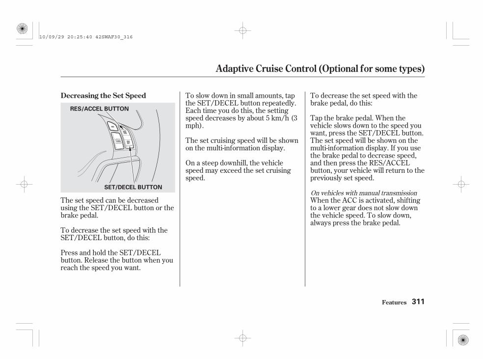
The set speed can be decreasedusing the SET/DECEL button or thebrake pedal.
To decrease the set speed with theSET/DECEL button, do this:
Press and hold the SET/DECELbutton. Release the button when youreach the speed you want.
To decrease the set speed with thebrake pedal, do this:
Tap the brake pedal. When thevehicle slows down to the speed youwant, press the SET/DECEL button.The set speed will be shown on themulti-information display. If you usethe brake pedal to decrease speed,and then press the RES/ACCELbutton, your vehicle will return to thepreviously set speed.
To slow down in small amounts, tapthe SET/DECEL button repeatedly.Each time you do this, the settingspeed decreases by about 5 km/h (3mph).
When the ACC is activated, shiftingto a lower gear does not slow downthe vehicle speed. To slow down,always press the brake pedal.
On a steep downhill, the vehiclespeed may exceed the set cruisingspeed.
The set cruising speed will be shownon the multi-information display.
On vehicles with manual transmission
Decreasing the Set Speed
Adaptive Cruise Control (Optional for some types)
Features 311
SET/DECEL BUTTON
RES/ACCEL BUTTON
10/09/29 20:25:40 42SWAF30_316

When the system detects a vehicleahead of you, a solid-line vehicle iconappears.
If there is no vehicle ahead of youwithin ACC range, a dotted-linevehicle icon will be on the multi-information display.
With ACC on, the distance betweenyour vehicle and the vehicle ahead ofyou is controlled and maintained.You can change this distance to oneof three ranges: long, middle, orshort.You can customize the ‘‘Pre-Running
Car Detect Beep’’ setting (see pagesand ).
To set the pre-running detect beeperon when the system detects a vehicle,see page . On the default setting,the pre-running detect beeper is setto off.
125125 126
Changing Vehicle DistanceDetecting a Vehicle Ahead of You
Adaptive Cruise Control (Optional for some types)
Features312
DISTANCE BUTTONDOTTED-LINE VEHICLE ICONSOLID-LINE VEHICLE ICON
km/h type is shown. km/h type is shown.
10/09/29 20:25:52 42SWAF30_317

To change the range, press theDISTANCE button. Each time youpress the button, the range changesfrom Long, to Middle, and then toShort.
The higher your vehicle speed is, thelonger the distance between thevehicle in front will be set as shownbelow.
The distance you select is alsoshown on the multi-informationdisplay.
Long
Middle
Short
80 km/h(50 mph)47 metres(154 feet)(2.1 sec)
34 metres(111 feet)(1.5 sec)
26 metres(85 feet)(1.2 sec)
104 km/h(65 mph)61 metres(200 feet)(2.1 sec)
42 metres(138 feet)(1.5 sec)
31 metres(101 feet)(1.1 sec)
The driver must in all circumstancespreserve a sufficient brakingdistance from the vehicle whichprecedes it and be aware thatminimum distances or times ofspacing can be provided by theprovisions of the Motorway Codelocally applicable and that it is thedriver’s responsibility to respectthose laws.
Adaptive Cruise Control (Optional for some types)
Features 313
LONG RANGE
MIDDLE RANGE
SHORT RANGE
Three horizontal bars
Two horizontal bars
One horizontal bar
km/h type is shown.
10/09/29 20:26:03 42SWAF30_318
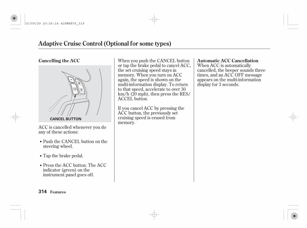
When ACC is automaticallycancelled, the beeper sounds threetimes, and an ACC OFF messageappears on the multi-informationdisplay for 3 seconds.
When you push the CANCEL buttonor tap the brake pedal to cancel ACC,the set cruising speed stays inmemory. When you turn on ACCagain, the speed is shown on themulti-information display. To returnto that speed, accelerate to over 30km/h (20 mph), then press the RES/ACCEL button.
ACC is cancelled whenever you doany of these actions:
Push the CANCEL button on thesteering wheel.
Press the ACC button. The ACCindicator (green) on theinstrument panel goes off.
Tap the brake pedal.
If you cancel ACC by pressing theACC button, the previously setcruising speed is erased frommemory.
Automatic ACC CancellationCancelling the ACC
Adaptive Cruise Control (Optional for some types)
Features314
CANCEL BUTTON
10/09/29 20:26:14 42SWAF30_319

Any of these conditions may causeACC to cancel:
If you turn the ignition switch to theACCESSORY (I) or LOCK (0)position after ACC was automaticallycancelled, the set speed is erased,and you must enter it again (seepage ).
If ACC is cancelled by any of theseconditions, wait until the conditionimproves, then press the RES/ACCEL button to restore ACC.When you do this, the vehicle willresume its set cruising speed.
The vehicle speed decreases tobelow approximately 25 km/h (17mph).
When the ABS or VSA is activated.
Abrupt steering wheel movement.
Driving on a mountainous road, ordriving off road for extendedperiods.
An abnormal tyre condition isdetected or the tyres are skidding.
The vehicle ahead of you cannotbe detected.
When the radar sensor in the frontgrille gets dirty.
Poor weather (rain, fog, snow, etc.)
When the trailer stability assistfunction is activated.
You shift into neutral temporarilywhen shifting into a higher orlower gear.
You press and hold the clutchpedal for a while at shifting.
The engine speed goes to below1,000 rpm.
The engine speed goes into thetachometer’s red zone.
Ignoring either shift up or downindication shown in thetachometer display will cancel theACC after about 10 seconds.
When the ABS or VSA systemindicator comes on.
308
On vehicles with manual transmission
Adaptive Cruise Control (Optional for some types)
Features 315
10/09/29 20:26:31 42SWAF30_320

The multi-information display showsvarious symbols related to ACC. Fora description of each ACC symbolyou may see, refer to the charts asfollows.
DescriptionSymbol/Message
ACC is on.
ACC is suspended.
A cruising speed can be set bypressing the SET/DECEL button.
ACC is standby, and the previouslyset cruising speed is in memory. Thepreviously set speed can be resumedby pressing the RES/ACCEL button.
Symbols on the Multi-informationDisplay
Adaptive Cruise Control (Optional for some types)
Features316
km/h type shown
10/09/29 20:26:40 42SWAF30_321

DescriptionSymbol/Message Symbol/Message
CONTINUED
Description
ACC detects a vehicle ahead of you.
ACC does not detect a vehicle aheadof you.
ACC has been automatically cancelledbecause its radar sensor in the frontgrille is dirty.
ACC has been automatically cancelledbecause of poor weather or otherconditions (see page 314).
You will hear three beeps.
Apply the brakes immediately. Yourvehicle is too close to the vehicleahead of it.
You will hear a continuous beep.
ACC needs to be checked.
Have your vehicle checked by adealer.
Adaptive Cruise Control (Optional for some types)
Features 317
km/h type shown
km/h type shown
10/09/29 20:26:52 42SWAF30_322

EC DirectivesThis radar sensor system complieswith the R & TTE (Radio equipmentand Telecommunications TerminalEquipment and the mutualrecognition of their conformity)Directives.
(EU models)
Adaptive Cruise Control (Optional for some types)
Features318
10/09/29 20:26:57 42SWAF30_323

All obstacles may not always besensed. Even when the system is on,you should look for obstacles nearyour vehicle to make sure it is safe topark.
The rear centre sensors work whenthe shift lever is in reverse (R), andthe vehicle speed is less than 8 km/h(5 mph).
If the parking brake is set (manualtransmission) or the shift lever is inthe Park position (automatictransmission), the parking sensorsystem will not be activated evenwith the ignition switch in the ON(II) position.
The system has two front cornersensors, two rear corner sensors,and two rear centre sensors.
Your vehicle has a parking sensorsystem. The system lets you knowthe approximate distance betweenyour vehicle and most obstacleswhile you are parking. When thesystem is on and your vehicle isnearing an obstacle, you will hear abeeping and see parking sensorindicators on the multi-informationdisplay.
To activate the system, push thebutton on the dashboard with theignition switch in the ON (II)position. The indicator in the buttoncomes on when the system is on.You will hear a beep. To turn thesystem off, push the button again.
Before moving your vehicle, makesure that the indicator in the buttoncomes on. If it is off, the parkingsensor system cannot be activated.
CONTINUED
Parking Sensor System (For some types)
Features 319
PARKING SENSOR SYSTEM BUTTON
Vehicle with headlight washer isshown.
10/09/29 20:27:09 42SWAF30_324

Example shown: Obstacle is at the left front of the vehicle.The corner sensors work only whenthe shift lever is in any position(except for Park on vehicles withautomatic transmission) and thevehicle speed is less than 8 km/h (5mph).
When you turn the system on, abeeper sounds once.
When the system senses an obstacle,the appropriate indicator comes on,and a beeper sounds as shown in thefollowing tables.
About 40-50 cm(16-20 in)
About 30-40 cm(12-16 in)
About 30 cm(12 in) or less
Upper left indicator stays on
Distance
Indicator
Beeper Steady Rapid Continuous
Corner Sensor Operation
Indicators and Beeper Operationon the Multi-information Display
Parking Sensor System (For some types)
Features320
10/09/29 20:27:21 42SWAF30_325

If the system develops a problem,you will see all indicators or theindicators with a ‘‘CHECK SYSTEM’’message on the multi-informationdisplay, and a beeper soundscontinuously.
Distance
Beeper
Indicator
About 0.6 m(24 in) or less
About 1-1.8 m(40-70 in)
About 0.6-1 m(24-40 in)
Steady ContinuousRapid
Bottom indicator stays on
CONTINUED
Rear Centre Sensor Operation
Parking Sensor System (For some types)
Features 321
10/09/29 20:27:31 42SWAF30_326

Very often, a sensor covered withmud, ice, snow, etc. is the cause ofthis display. Check the sensors first.If the indicators stay on or thebeeper does not stop, have thesystem checked by your dealer.
If there is a problem in any of thesensors, the appropriate sensorindicator(s) will come on and stay on.In this case, the remaining sensorscan be operated properly.
The range of the corner sensors andthe rear centre sensor are limited.Each corner sensor is capable ofsensing an obstacle only when yourvehicle is 50 cm (20 in) or closer.
If there is a problem with theparking sensor system and/or abeeper sounds continuously, youmay turn off the system temporarilyand stop the beeper by pressing theparking sensor system button.
The rear centre sensor senses anobstacle that is behind your vehicle1.8 m (70 in) or closer.
Do not put any accessories on oraround the sensors.
Parking Sensor System (For some types)
Features322
Within about 50 cm (20 in) Within about 1.8 m (70 in)
10/09/29 20:27:41 42SWAF30_327

The system may not functionproperly under these conditions:
The sensors are covered withsnow, ice, mud, etc.
When the vehicle is on a roughroad, on grass, or on a hill.
After the vehicle has been sittingout in hot or cold weather.
When the system is affected bysome electrical equipment ordevices generating an ultrasonicwave.
When operating the vehicle in badweather.
The system may not sense thin orlow objects, or sonic-absorptivematerials such as snow, cotton, orsponge.
The system cannot sense objectsdirectly under the bumper.
If you install a towbar on yourvehicle, this may cause the alarmwhen the parking sensor system isactivated.
When you tow a trailer, do not turnon the parking sensor system. Thetrailer behind your vehicle will causethe alarm to be activated.
Parking Sensor System (For some types)
Features 323
10/09/29 20:27:51 42SWAF30_328
On vehicles with navigation systemRefer to the navigation systemmanual for operation of the rearviewcamera.
Rearview Camera and Monitor (For some types)
Features324
10/09/29 20:27:57 42SWAF30_329

-
-
Press andrelease to give a command or answera call.
Press andrelease to end a call, go back to theprevious command, or cancel thecommand.
Hands-Free Telephone (HFT) allowsyou to place and receive phone callsusing voice commands, withouthandling your mobile phone.
To use HFT, you need a Bluetooth-compatible mobile phone. For a listof compatible phones, pairingprocedures, and special featurecapabilities:
Air or wind noise from thedashboard and side vents and allwindows may interfere with themicrophone. Adjust or close themas necessary.
Press and release the HFT Talkbutton each time you want tomake a command. After the beep,speak in a clear, natural tone.
All phones may not operateidentically, and some may causeinconsistent operation of the HFTsystem.
Before selling or discardingyour vehicle, make sure to delete thestored phone data.
CONTINUED
Using HFT
HFT Talk button
HFT Back button
Visit
HFT ButtonsVoice Control Tips
www.hondahandsfree.com
Hands-Free Telephone (HFT) System (For some types)
Features 325
NOTE:
HFT BACK BUTTON
NAVI VOICECONTROLBUTTONS
HFTTALKBUTTON
MICROPHONE
10/09/29 20:28:12 42SWAF30_330

####
Try to reduce all backgroundnoise. If the microphone picks upvoices other than yours,commands may be misinterpreted.
Many commands can be spokentogether. For example, you cansay ‘‘Call 123-456- ’’ or‘‘Dial Peter.’’
When HFT is in use, navigationvoice commands cannot berecognised.
To change the volume level ofHFT, use the audio system volumeknob or the steering wheel volumecontrols.
To hear general HFT information,including help on using HFTbuttons, Voice control, or makinga call, say ‘‘Tutorial.’’
For help at any time, including alist of available commands, say‘‘Hands free help.’’
As an incoming call notification, youwill see the following display:
However, when the current street isshown, and AUDIO INFO icon isvisible, ‘‘TEL’’ will not appear whenthere is an incoming call.
When there is an incoming call, orHFT is in use, ‘‘TEL’’ will appear atthe bottom of the map screen.
Information DisplayHelp Features
Hands-Free Telephone (HFT) System (For some types)
Features326
HFT MASSAGE
BLUETOOTH ICON
10/09/29 20:28:23 42SWAF30_331

A notification that there is anincoming call, or HFT is in use, willappear on the navigation screenwhen the audio system is on.
The ‘‘ ’’ indicator will alsoappear when a phone is linked.
The Bluetooth icon will alsoappear on the display when a phoneis linked.
Hands-Free Telephone (HFT) System (For some types)
Features 327
BLUETOOTH ICON
10/09/29 20:28:31 42SWAF30_332

####
How to Use HFT
Hands-Free Telephone (HFT) System (For some types)
Features328
‘‘Phone Setup’’
‘‘Call’’ or ‘‘Dial’’
‘‘Pair’’
‘‘Edit’’
‘‘Delete’’
‘‘Jim Smith’’
‘‘Set PairingCode’’
The ignition switch must be in the ACCESSORY (I) or ON (II) position.
‘‘List’’
‘‘Status’’
‘‘Next Phone’’
Press HFTTalk button
Press and release the HFT Talk button each time you give a command.
Pair a phone to the system
Edit the name of a paired phone
Delete a paired phone from the system
Hear a list of all phones paired to the system
Hear which paired phone is currently linked to the system
Search for another previously paired phone to link to
Set the pairing code to a ‘‘Fixed’’ or ‘‘Random’’ number
Enter desired phone number
Once a phonebook entry is stored, you can say a name here.
‘‘123-456- ’’
(See page 331)
(See page 332)
(See page 332)
(See page 332)
(See page 333)
(See page 333)
(See page 333)
(See page 334)
(See page 335)
10/09/29 20:28:39 42SWAF30_333

CONTINUED
Hands-Free Telephone (HFT) System (For some types)
Features 329
‘‘Redial’’
‘‘Transfer’’
‘‘Mute’’
‘‘Send’’
‘‘Phonebook’’
‘‘Store’’
‘‘Edit’’
‘‘Delete’’
‘‘ReceiveContact’’
‘‘List’’
Press HFTTalk button
Press and release the HFT Talk button each time you give a command.
Mute your voice to the person at the other end of the call
Store a phonebook entry
Edit the number of an existing phonebook entry
Delete a phonebook entry
If your phone supports this function, use this to transfer contacts fromyour phone to HFT
Hear a list of all stored phonebook entries
Redial the last number called
Transfer a call from HFT to your phone, or from your phone to HFT
Send numbers or names during a call
(See page 335)
(See page 338)
(See page 338)
(See page 339)
(See page 339)
(See page 340)
(See page 340)
(See page 341)
(See page 341)
10/09/29 20:28:46 42SWAF30_334

Hands-Free Telephone (HFT) System (For some types)
Features330
‘‘Clear’’
‘‘Auto Transfer’’
‘‘Call Notification’’
‘‘Security’’
‘‘Tutorial’’
‘‘Hands Free Help’’
‘‘SystemSet up’’
Press HFTTalk button
Press and release the HFT Talk button each time you give a command.
‘‘Change Language’’
Apply a security passcode to the system that must be input at each keycycle to access the system
Change your security password
Set how you would like to be notified of an incoming call
Set calls to automatically transfer from your phone to HFT when youenter the vehicle
Clear the system of all paired phones, phonebook entries and securitypassword
Change language from English to other available one
Hear a tutorial for general rules on using the system
Hear a list of available commands and additional information describing each command
‘‘Change Password’’
(See page 346)
(See page 346)
(See page 347)
(See page 347)
(See page 347)
(See page 348)
(See page 326)
(See page 326)
10/09/29 20:28:55 42SWAF30_335

To use HFT, you need to pair yourBluetooth-compatible mobile phoneto the system.
This command group is available forpaired mobile phones.
You cannot pair your phone whilethe vehicle is moving.
Your phone must be in discoveryor search mode to pair. Refer toyour phone’s manual.
Up to six phones can be paired.
Your phone’s battery may drainfaster when it is paired to HFT.
If after three minutes your phoneis not ready to pair or a phone isnot found, the system will time outand return to idle.
Press and release the HFT Talkbutton. If you are pairing a phonefor the first time, HFT will giveyou information about the pairingprocess. If it is not the first phoneyou are pairing, say ‘‘
’’ and say ‘‘ .’’
Follow the HFT prompts and putyour phone in discovery or searchmode. HFT will give you a 4-digitpairing code and begin searchingfor your phone.
When your phone finds aBluetooth device, select HFT fromthe options and enter the 4-digitcode from the previous step.
Follow the HFT prompts andname the newly paired phone.
1.
2.
3.
4.
CONTINUED
Phone Setup
Phonesetup Pair
Phone pairing tips
To pair a mobile phone:
Hands-Free Telephone (HFT) System (For some types)
Features 331
10/09/29 20:29:09 42SWAF30_336

Press and release the HFT Talkbutton before a command.
Say ‘‘ ’’ after the prompts.
Say ‘‘ .’’
Say ‘‘ ’’ after the prompts.
Say ‘‘ .’’
Press and release the HFT Talkbutton before a command. Press and release the HFT Talk
button before a command.
HFT will read out all the pairedphone’s names.
Say ‘‘ ’’ after the prompts.
Say ‘‘ .’’
If there is more than one phonepaired to the system, HFT will askyou which phone’s name you wantto change. Follow the HFTprompts and rename the phone.
HFT will ask you which phone youwant to delete. Follow the HFTprompts to continue with thedeletion.
1.
2.
3.
1.
2.
3.
1.
2.
3.
To rename a paired phone: To hear the names of all pairedphones:
To delete a paired phone:
Edit
Phone setup
Delete
Phone setup
List
Phone setup
Hands-Free Telephone (HFT) System (For some types)
Features332
10/09/29 20:29:25 42SWAF30_337

Say ‘‘ .’’
Say ‘‘ ’’ after the prompts.
HFT will tell you which phone islinked to the system.
Press and release the HFT Talkbutton before a command.
Press and release the HFT Talkbutton before a command.
Say ‘‘ ’’ after theprompts.
Say ‘‘ .’’
If no other phones are found orpaired, HFT will inform you that theoriginal phone is linked again.
Once another phone is found, it islinked to the system. HFT willinform you which phone is nowlinked.
HFT disconnects the linked phoneand searches for another pairedphone.
Press and release the HFT Talkbutton before a command.
Say ‘‘ .’’
Say ‘‘ ’’ after theprompts.
If you want HFT to create arandom code each time you pair aphone, say ‘‘ .’’ If you wantto choose your own 4-digit code tobe used each time, say ‘‘ ’’and follow the HFT prompts.
1.
2.
3.
1.
2.
3.
4.
1.
2.
3.
To hear which paired phone iscurrently linked:
To change from the currently linkedphone to another paired phone:
To change the pairing code setting:
Phone setup
Status Next phone
Phone setupPhone setup
Set pairing code
Random
Fixed
Hands-Free Telephone (HFT) System (For some types)
Features 333
10/09/29 20:29:41 42SWAF30_338

Press and release the HFT Talkbutton before a command.
Say ‘‘ ’’ or ‘‘ .’’
Follow the HFT prompts and saythe phone number you want to dial.
Follow the HFT prompts toconfirm the number and say‘‘ ’’ or ‘‘ .’’
Once connected, you will hear theperson you called through the audiospeakers.
You can make calls using any phonenumber or a name in the HFTphonebook. You can also redial thelast number called.
Select ‘‘ .’’
Press the INFO button, then select‘‘ .’’
Bluetooth is the wireless technologythat links your phone to HFT. HFTuses a Class 2 Bluetooth, whichmeans, the maximum range betweenyour phone and vehicle is 10 meters(30 feet).
During a call, HFT allows you to talkup to 30 minutes after you removethe key from the ignition switch.However, this may weaken thevehicle’s battery.
1.
2.
3.
1.
2.
To make a call using a phone number(talk button):
To make a call using a phone number(navigation display):
Call Dial
Call Dial
Making a Call
Dial
Mobile Phonebook
Hands-Free Telephone (HFT) System (For some types)
Features334
10/09/29 20:29:55 42SWAF30_339

Press the INFO button, then select‘‘ .’’
Select ‘‘ .’’
Press and release the HFT Talkbutton before a command.
Say ‘‘ ’’ or ‘‘ .’’
Follow the HFT prompts and saythe name stored in the HFTphonebook that you want to call.
Follow the HFT prompts toconfirm the name and make thecall.
Press and release the HFT Talkbutton and say ‘‘ .’’
To end the call, select ‘‘ .’’
To make the call, select ‘‘ .’’
The navigation display will changeas shown above. Enter a callnumber.
1.
2.
1.
2.
3.
3.
4.
5.
CONTINUED
Mobile Phonebook
Search
Call Dial
Redial
Hang-up
CALL
To make a call from an importedphonebook:
To make a call using a name in theHFT phonebook:
To redial the last number called byHFT:
Hands-Free Telephone (HFT) System (For some types)
Features 335
10/09/29 20:30:12 42SWAF30_340

If the phonebook you select is PIN-protected, you will need to enter thePIN to access it. See page formore information.
Select a phonebook you want tochoose a phone number from.
To display all names in thephonebook, select the ‘‘ ’’option.
To search for a specific name inthe phonebook, enter the keywordfor either the first or last name.
Select the phone number, andHFT begins dialing.
Select the name. All the phonenumbers stored for that name willbe listed.
4.
5.
3.
344 List
Hands-Free Telephone (HFT) System (For some types)
Features336
List ICON
10/09/29 20:30:24 42SWAF30_341

If your phone has Call Waiting, pressand release the HFT Talk button toput the original call on hold andanswer the incoming call.
To return to the original call, pressthe HFT Talk button again. If youdon’t want to answer the incomingcall, disregard it and continue withyour original call. If you want to hangup the original call and answer thenew call, press the HFT Back button.
If you choose ‘‘ ,’’the phone number will be stored inHFT, so that you can call it usingHFT’s name tag by voice.
You can also make a call from yourpaired phone in the vehicle. The callwill be transferred to HFTautomatically.
When you receive a call, an incomingcall notification (if activated) willplay and interrupt the audio systemif it is on.
Press the HFT Talk button toanswer the call, or the HFT Backbutton to hang up.
Never try to dial from yourphone directly if the vehicle ismoving.
Call Waiting
To make a call using a paired phonevia HFT
Store in HFT Unit Receiving a Call
Hands-Free Telephone (HFT) System (For some types)
Features 337
NOTE:
10/09/29 20:30:35 42SWAF30_342

You can transfer a call from HFT toyour phone, or from your phone toHFT.
Press and release the HFT Talkbutton and say ‘‘ .’’
A call on the phone will beautomatically transferred to the HFTsystem when you get into the vehicleand turn on the ignition switch.
If you make a call from your phonewhile in the vehicle, the call will alsobe transferred to the HFT system.
Never try to dial from yourphone directly if the vehicle ismoving.
You can mute your voice to theperson you are talking to during acall.
To mute your voice during a call,press and release the HFT Talkbutton and say ‘‘ .’’
To unmute your voice, press andrelease the HFT Talk button and say‘‘ ’’ again.
Transferring a Call
Transfer
Muting a Call
Mute
Mute
Automatic Transferring
Hands-Free Telephone (HFT) System (For some types)
Features338
NOTE:
10/09/29 20:30:47 42SWAF30_343

#
HFT allows you to send numbers ornames during a call. This is usefulwhen you call a menu-driven phonesystem.
Press and release the HFT Talkbutton before a command.
Say ‘‘ .’’
Follow the HFT prompts and saythe name or number you want tosend.
Follow the HFT prompts to sendthe tones and continue the call.
To send a hash ( ), say‘‘hash.’’ To send a star (*), say ‘‘star.’’
You can store up to 50 names withtheir associated numbers on HFT.The numbers you store cannot beonly phone numbers but other types,such as account numbers orpasswords, which can be sent duringa menu-driven call.
Say ‘‘ .’’
Say ‘‘ ’’ after the prompts.
Say the number you want to storefor the name entry.
Follow the HFT prompts and say‘‘ ’’ to store the entry.
Say a name you want to list as yourphonebook entry.
Press and release the HFT Talkbutton before a command.
1.
2.
3.
1.
2.
3.
4.
5.
CONTINUED
Send Numbers or Names Duringa Call
Send
Phonebook
Phonebook
Store
Enter
To send a name or number during acall:
To store a phonebook entry:
Hands-Free Telephone (HFT) System (For some types)
Features 339
NOTE:
10/09/29 20:31:03 42SWAF30_344

Avoid using duplicate nameentries.
Avoid using ‘‘home’’ as a nameentry.
It is easier for HFT to recognise amultisyllabic or longer name. Forexample, use ‘‘ ’’ instead of‘‘ ,’’ or ‘‘ ’’ insteadof ‘‘ .’’
Press and release the HFT Talkbutton before a command.
Say ‘‘ .’’
Say ‘‘ ’’ after the prompts.
Follow the HFT prompts and saythe name entry you want to edit.
When asked, say the new numberfor that name.
Follow the HFT prompts tocomplete the edit.
Press and release the HFT Talkbutton before a command.
Say ‘‘ .’’
Say ‘‘ ’’ after the prompts.
Say the name you want to deleteand follow the HFT prompts tocomplete the deletion.
1.
2.
3.
4.
5.
1.
2.
3.Peter
Pete John SmithJohn
Phonebook
Edit
Phonebook
Delete
To edit the number stored in a name: To delete a name:
Hands-Free Telephone (HFT) System (For some types)
Features340
NOTE:
10/09/29 20:31:19 42SWAF30_345

Press and release the HFT Talkbutton before a command.
Say ‘‘ .’’
Say ‘‘ ’’ after the prompts.
HFT begins reading the names inthe order they were stored.
If you hear a name you want to call,immediately press the HFT Talkbutton and say ‘‘ .’’
Press and release the HFT Talkbutton before a command.
Say ‘‘ .’’
Say ‘‘ ’’ after theprompts.
Follow the HFT prompts, select anumber from your mobile phone,and send it to HFT.
Follow the HFT prompts andname the number, or say‘‘ ’’ if it is not the numberyou want to store.
Follow the HFT prompts if youwant to store another number.
If you selectfrom the Information screen menu,you will see four HFT options.
For a list of mobile phones that arecompatible with this feature:
4.
1.
2.
3.
4.
1.
2.
3.
5.
CONTINUED
To list all names in the phonebook: To store a specific phone numberfrom your mobile phone directly tothe HFT phonebook (available onsome phones):
(available on some phones)
www.hondahandsfree.com
Phonebook
List
Call
Phonebook
Receive contact
Discard
Mobile Phonebook
Mobile Phonebook
Visit
Hands-Free Telephone (HFT) System (For some types)
Features 341
10/09/29 20:31:35 42SWAF30_346

The entire phonebook data of themobile phone that is linked to HFTcan be imported to the navigationsystem.
Select ‘‘ ,’’ and HFT will beginimporting the phonebook. Select‘‘ ’’ after the import is completed.
Select ‘‘ ,’’ and a list ofimported phonebooks will bedisplayed.
Select a phonebook from the list.
Once a phonebook has beenimported, you can search the phonenumbers by the person’s name.
If the phonebook is PIN-protected,you will need to enter the 4-digit PIN.
Import: Search:
Import
OK
Search
Hands-Free Telephone (HFT) System (For some types)
Features342
IMPORTED PHONEBOOK
IMPORTED DATE
PIN ICON
10/09/29 20:31:49 42SWAF30_347

To search for a specific name in thephonebook, enter the keyword foreither the first or last name.
To display all names in thephonebook, select the ‘‘ ’’ option.
Select a person from the list. Up tothree category icons are displayed inthe left side of the list:
These indicate how many numbersare stored for the name. If a namehas more than three category icons,‘‘…’’ is displayed.
Select the person’s number you wantto call, and press the HFT Talkbutton.
CONTINUED
List
Hands-Free Telephone (HFT) System (For some types)
Features 343
Preference
Home
Mobile
Work
Pager
Fax
Car
Voice
Other
List ICON
10/09/29 20:32:05 42SWAF30_348

After making a selection, thefollowing screen will appear.
Select ‘‘ ,’’ then ‘‘ ’’ to completethe deletion.
You can add, change, or remove aPIN number from any phonebook.
If you have selected a phonebookwithout a PIN, you will see the abovedisplay.
Enter the new 4-digit PIN. You willhave to re-enter the PIN forconfirmation.
You can delete any importedphonebook.
Select ‘‘ ,’’ and a list ofimported phonebooks will bedisplayed.
Select a phonebook you want todelete. If the phonebook is PIN-protected, you will need to enter the4-digit PIN number.
Yes OK
PIN Number
Delete
To add a PIN:
Delete:
Hands-Free Telephone (HFT) System (For some types)
Features344
10/09/29 20:32:18 42SWAF30_349

Select ‘‘ ,’’ then select‘‘ ’’ after you enterthe current PIN.
The display will change as shownabove.
Enter the new 4-digit PIN number.You will be asked to re-enter the PINfor verification.
Select the phonebook you want. Thedisplay will change as shown above.
Enter the current PIN for thisphonebook.
To remove a PIN:To change the PIN to a new number:PIN number
Do not use PIN
Hands-Free Telephone (HFT) System (For some types)
Features 345
10/09/29 20:32:28 42SWAF30_350

This command group allows you tochange or customize HFT’s basicsettings.
Press and release the HFT Talkbutton before a command.
Say ‘‘ ’’ after the prompts.
Follow the HFT prompts and saythe 4-digit password you want toset.
Follow the HFT prompts toconfirm the number.
Once a password is set, youwill need to enter it to use HFT eachtime you start the vehicle. If youforget the password, your dealer willhave to reset it for you, or you willhave to clear the entire system (seepage ).
Say ‘‘ ’’ after theprompts.
Follow the HFT prompts and saythe new 4-digit password.
Follow the HFT prompts toconfirm the number.
Say ‘‘ .’’
Press and release the HFT Talkbutton before a command.
Say ‘‘ .’’1.
2.
3.
4.
1.
2.
3.
4.
347
System Setup
SecurityChange password
System setupSystem setup
To set a 4-digit password to lock theHFT system for security purposes:
To change your security passcode:
Hands-Free Telephone (HFT) System (For some types)
Features346
NOTE:
10/10/14 15:41:08 42SWAF30_351
*
*
Press and release the HFT Talkbutton before a command.
Say ‘‘ .’’
Say ‘‘ ’’ after theprompts.
Follow the HFT prompts and say‘‘ ’’ or ‘‘ .’’ Youcan also say ‘‘ ’’ for no audibleincoming call notification.
If you get into the vehicle while youare on the phone, the call can beautomatically transferred to HFTwith the ignition switch in theACCESSORY (I) or ON (II) position.
Press and release the HFT Talkbutton before a command.
Say ‘‘ .’’
Say ‘‘ ’’ after theprompts.
HFT will let you know if autotransfer is on or off, depending onthe previous setting. Follow theHFT prompts to change thesetting.
You can also clear the system whenyou have forgotten the password andcannot access HFT. When HFT asksyou for the password, say ‘‘
.’’ Paired phones, all names inthe HFT phonebook and all importedphonebook data will be lost.
Press and release the HFT Talkbutton before a command.
Follow the HFT prompts tocontinue to complete the clearingprocedure.
Say ‘‘ .’’
This operation clears the password,paired phones, all names in the HFTphonebook, and all importedphonebook data.
Say ‘‘ ’’ after the prompts.
The default setting is a ring tone.
1.
2.
3.
1.
2.
3.
:
1.
2.
3.
To select either a ring tone or aprompt as the incoming callnotif ication :
To activate or deactivate the autotransfer function:
To clear the system:
System setup
Call notif ication
Ring tone PromptOff
System setup
Auto transfer
Systemclear
System setup
Clear
Hands-Free Telephone (HFT) System (For some types)
Features 347
10/09/29 20:33:02 42SWAF30_352

Press and release the HFT Talkbutton before a command.
Say ‘‘ .’’
Follow the HFT prompts to selectthe desired language.
If you have not named your pairedphone in the language you justselected, HFT will ask you to name itin the current language.
Press and release the HFT Talkbutton and say a command.
Say the language you want tochange to in that language.
Follow the HFT prompts.
For example, when French is yourcurrently selected language, you cangive voice commands in French.
The name and logos areregistered trademarks owned byBluetooth SIG, Inc. and any use ofsuch marks by Honda Motor Co.,Ltd. is under licence. Othertrademarks and trade names arethose of their respective owners.1.
2.
1.
2.
BluetoothChange Language
Change language
Quick Language Selection Wireless TechnologyTo change the system languagebetween English, French, Italian,German and Spanish:
To quickly change the language:Bluetooth
Hands-Free Telephone (HFT) System (For some types)
Features348
10/09/29 20:33:17 42SWAF30_353

When using voice control, the HFTsystem call is placed on hold, or theHFT system stops its voicerecognition. The HFT system callwill continue when voice controlcommand is ended. To operate theHFT system again, press the Talkbutton. Then after the beep, say theappropriate command.
In addition, you cannot use the HFTsystem while receiving a PTY alarm.
Hereby,declares that this
is in compliancewith the essential requirements andother relevant provisions of Directive1999/5/EC.
www.jciblueconnect.com/faq/EU_DoC.pdf
For additional conformanceinformation: www.jciblueconnect.com/faq
For information of DoC (Declaration ofConformance)
Johnson Controls Automotive,Hands-Free
Telephone System
EU models
Except EU models
HFT System Limitations
Hands-Free Telephone (HFT) System (For some types)
Features 349
10/09/29 20:33:25 42SWAF30_354

350
10/09/29 20:33:28 42SWAF30_355

Before you begin driving yourvehicle, you should know what fuelto use and how to check the levels ofimportant fluids. You also need toknow how to properly store luggageor packages. The information in thissection will help you. If you plan toadd any accessories to your vehicle,please read the information in thissection first.
.............................Break-in Period . 352.................Fuel Recommendation . 352
............................Petrol models . 352
............................Diesel models . 353.........Service Station Procedures . 354
....................................Refueling . 354Opening and Closing
.............................the Bonnet . 356...................................Oil Check . 357
.............Engine Coolant Check . 360........................Fuel Cutoff Switch . 361
...............................Fuel Economy . 362...Accessories and Modifications . 363
.........................Carrying Luggage . 365
Before Driving
Before Driving 351
10/09/29 20:33:33 42SWAF30_356

*
*
*
**
Help assure your vehicle’s futurereliability and performance by payingextra attention to how you driveduring the first 1,000 km.During this period:
Avoid full-throttle starts and rapidacceleration.
Avoid hard braking for the first300 km.
Do not change the oil until thescheduled maintenance time.
You should also follow theserecommendations with anoverhauled or exchanged engine, orwhen the brakes are replaced.
Do not tow a trailer.
Using petrol containing lead will damage your vehicle’s emissionscontrols and engine. This contributes to air pollution.
See the ENGINE NUMBER on engine assembly (see page ).
Petrol of the recommended Research Octane Number (RON) may not beavailable in some areas. In this case, petrol of a lower octane may be usedtemporarily if it does not cause engine ‘‘knocking.’’ This will result indecreased engine performance.
Oxygenated fuels are blended with petrol and ethanol or ether compound.Your vehicle is also designed to operate on oxygenated fuels containing upto 10% ethanol by volume and up to 22% ETBE by volume, based on theEN228 standards. For more information, ask your dealer.
1 :2 :
566
TypeUNLEADEDUNLEADED
Recommended PetrolEngine TypeID
R20A2K24Z4
RON (MIN)9591
2
2
1
(For EU countries)
Break-in Period, Fuel Recommendation
Break-in Period Fuel Recommendation
Before Driving
Petrol models
Oxygenated Fuels
352
10/09/29 20:33:49 42SWAF30_357

CONTINUED
Your vehicle is designed to use onlyDiesel Fuel (also known asAutomotive gas oil and Derv).
The quality of diesel fuel (Derv) canvary in different countries, and onlyclean and good quality fuel should beused.
You need to use the proper fuel forEN590 and also vary the fueldepending on the season.
Your vehicle is designed to use onlyDiesel Fuel (also known asAutomotive gas oil and Derv).
You need to use proper Ultra LowSulfur Diesel fuel and vary the fueldepending on the season.
Your vehicle is not designed to useBiodiesel. For more information, askyour dealer.
The quality of diesel fuel (Derv) canvary in different countries, and onlyclean and good quality fuel should beused.
Your vehicle is not designed to useBiodiesel (pure or highconcentration more than specified byEN590). For more information, askyour dealer.
Select the proper fuel according tothe regional or climatic conditions.Use of inadequate fuel may reduceengine power. In this case, thesymbol ‘‘PGM-FI’’ may appear on themulti-information display.
The engine peak power may berestricted at starting the enginewhen the outside temperature isextremely low.This will help the fuel flow for thenormal engine operation.
For proper fuel selection, ‘‘DIESEL’’is marked on the fuel fill cap.
Serious damage may occur if petrolis used in diesel engines.
Except for South Africa models For South Africa models only
Before Driving
Diesel modelsDiesel models
Fuel Recommendation
353
10/09/29 20:34:03 42SWAF30_358
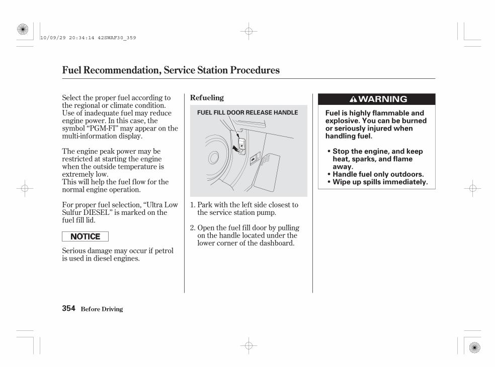
Park with the left side closest tothe service station pump.
Open the fuel fill door by pullingon the handle located under thelower corner of the dashboard.
Select the proper fuel according tothe regional or climate condition.Use of inadequate fuel may reduceengine power. In this case, thesymbol ‘‘PGM-FI’’ may appear on themulti-information display.
The engine peak power may berestricted at starting the enginewhen the outside temperature isextremely low.This will help the fuel flow for thenormal engine operation.
For proper fuel selection, ‘‘Ultra LowSulfur DIESEL’’ is marked on thefuel fill lid.
Serious damage may occur if petrolis used in diesel engines.
1.
2.
Refueling
Fuel Recommendation, Service Station Procedures
Before Driving354
Fuel is highly flammable andexplosive. You can be burnedor seriously injured whenhandling fuel.
Stop the engine, and keepheat, sparks, and flameaway.Handle fuel only outdoors.Wipe up spills immediately.
FUEL FILL DOOR RELEASE HANDLE
10/09/29 20:34:14 42SWAF30_359
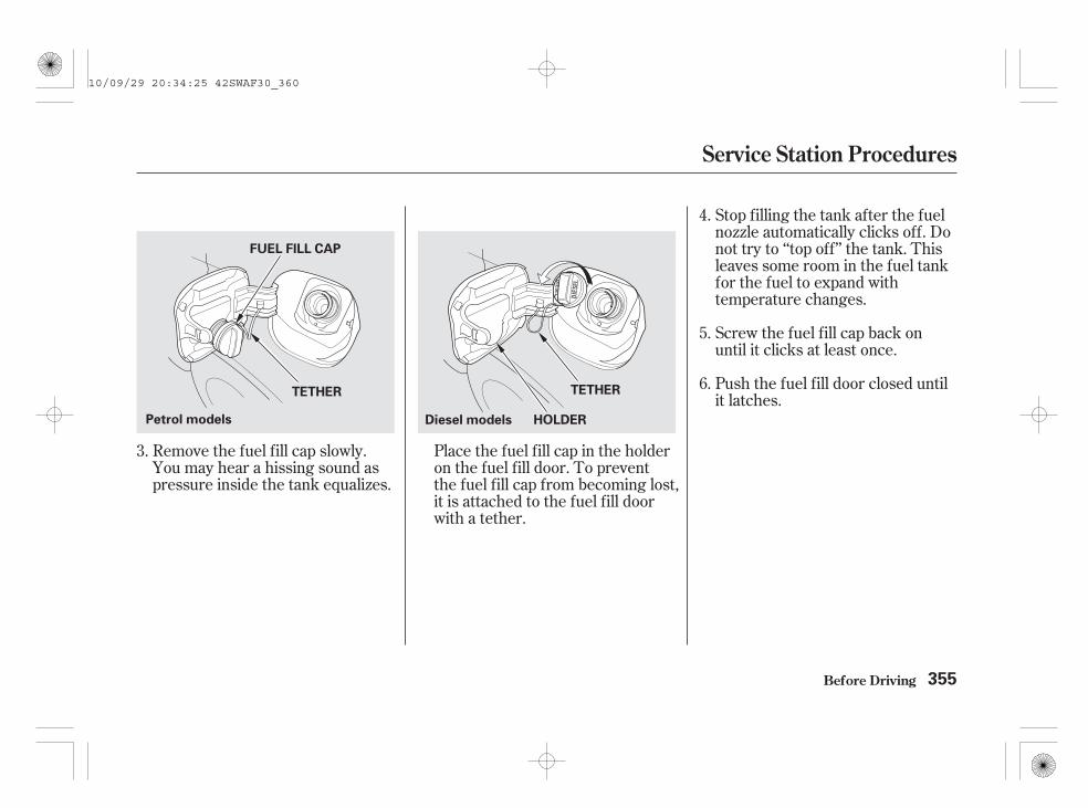
Stop filling the tank after the fuelnozzle automatically clicks off. Donot try to ‘‘top off’’ the tank. Thisleaves some room in the fuel tankfor the fuel to expand withtemperature changes.
Screw the fuel fill cap back onuntil it clicks at least once.
Push the fuel fill door closed untilit latches.
Remove the fuel fill cap slowly.You may hear a hissing sound aspressure inside the tank equalizes.
Place the fuel fill cap in the holderon the fuel fill door. To preventthe fuel fill cap from becoming lost,it is attached to the fuel fill doorwith a tether.
4.
5.
6.
3.
Service Station Procedures
Before Driving 355
Diesel models HOLDER
FUEL FILL CAP
Petrol models
TETHER TETHER
10/09/29 20:34:25 42SWAF30_360

Put your fingers between the frontedge of the bonnet and the frontgrille. The bonnet latch handle isabove the ‘‘H’’ logo. Push thishandle up to release the bonnet.Lift the bonnet.
Park the vehicle, and set theparking brake. Pull the bonnetrelease handle under the lowercorner of the dashboard. Thebonnet will pop up slightly.
If the bonnet latch handle movesstiffly, or if you can open thebonnet without lifting the handle,the mechanism should be cleanedand lubricated.
Holding the grip, pull the supportrod out of its clip. Insert the endinto the hole in the bonnetdesignated by an arrow.
1. 2. 3.
Opening and Closing the Bonnet
Service Station Procedures
Before Driving356
BONNET RELEASE HANDLEGRIP
CLIP
LATCHSUPPORT ROD
10/09/29 20:34:34 42SWAF30_361
To close the bonnet, lift it up slightlyto remove the support rod from thehole. Put the support rod back intoits holding clip. Lower the bonnet toabout 30 cm (a foot) above thefender, then let it drop. Make sure itis securely latched.
All engines consume oil as part oftheir normal operation, therefore,the engine oil level must be checkedregularly, for example whenrefuelling. Always check the oilbefore a long journey.
The amount of oil consumeddepends on how the vehicle is drivenand the climatic and road conditionsencountered. The rate of oilconsumption can be up to 1 litre per1,000 km/625 miles. Consumption islikely to be higher when the engineis new.
Make sure the engine is warmed upand the vehicle is parked on levelground. Turn off the engine and waitapproximately 3 minutes beforechecking the oil level.
Do not press the engine coverforcibly. This may damage theengine cover and component parts.
CONTINUED
On Diesel models
Oil Check
Service Station Procedures
Before Driving 357
10/09/29 20:34:43 42SWAF30_362

Remove the dipstick (orangehandle).
Remove the dipstick carefully, soyou do not spill the oil. Spilled oilcould damage components in theengine compartment.
Wipe off the dipstick with a cleancloth or paper towel.
Insert the dipstick all the way backinto its hole.
1.
2.
3.
Service Station Procedures
Before Driving358
2.0 engine model
DIPSTICK(Orange handle)
2.4 engine model
DIPSTICK (Orange handle) DIPSTICK (Orange handle)
Diesel models
10/09/29 20:34:52 42SWAF30_363

Remove the dipstick again, andcheck the level. It should bebetween the upper and lowermarks.
If it is near or below the lower mark,see on page
on petrol models, on dieselmodels.
4.
442 444
Service Station Procedures
Before Driving
Adding Engine Oil
359
UPPER MARK
LOWER MARK
UPPER MARK
LOWER MARK
2.0 engine model 2.4 engine model
UPPER MARK
LOWER MARK
Diesel models
10/09/29 20:35:00 42SWAF30_364

The coolant level in the expansiontank should be checked only whenthe engine and the cooling systemare cold. Make sure it is between theMAX and MIN lines. If it is belowthe MIN line, see
on page .
Refer toon page for information
about checking other items on yourvehicle.
Look at the coolant level in theradiator reserve tank. Make sure it isbetween the MAX and MIN lines. Ifit is below the MIN line, see
on page forinformation on adding the propercoolant.
446
448
428
Adding EngineCoolant
Owner’s MaintenanceChecks
Engine Coolant Check
AddingEngine Coolant
On Diesel modelsOn Petrol models
Service Station Procedures
Before Driving360
MAX MIN
Diesel models EXPANSION TANKRESERVE TANKPetrol models
MAX MIN
10/09/29 20:35:11 42SWAF30_365

The fuel cutoff switch is behind theinstrument panel. To access theswitch, turn the handle anticlockwiseon the lower instrument panel, thenremove the cover while releasing thetab. Extend your arm to the back ofthe instrument panel from theunderside.
In a collision or sudden impact, thisswitch automatically cuts off the fuelsupply to the engine.
After the switch has activated, itmust be reset by pressing the buttonbefore the engine can be restarted.
Before Driving
Fuel Cutoff Switch (For some types)
361
Leaking fuel can ignite orexplode, causing you to beseriously or fatally injured.
Always check for fuel leaksbefore resetting the switch.
HANDLE
COVER
SWITCH
10/09/29 20:35:18 42SWAF30_366

Always maintain your vehicleaccording to the maintenanceschedule. See
(see page).
an underinflated tyrecauses more ‘‘rolling resistance,’’which uses more fuel.
The build-up of snow or mud onyour vehicle’s underside addsweight and rolling resistance.Frequent cleaning helps your fueleconomy and reduces the chanceof corrosion.
Drive moderately. Rapidacceleration, abrupt cornering,and hard braking use more fuel.
Always drive in the highest gearpossible.
Shift up and shift down indicatorson the instrument panel show thebest timing to shift to a higher orlower gear, so you will keep theengine operating in its mosteconomical range.
Try to maintain a constant speed.Every time you slow down andspeed up, your vehicle uses extrafuel. If equipped, use the cruisecontrol or adaptive cruise control(ACC) when appropriate.
Combine several short trips intoone.
The air conditioning puts an extraload on the engine which makes ituse more fuel. Use the fresh-airventilation when possible.
428
For example,
On vehicles with manual transmissionImproving Fuel Economy
Owner’sMaintenance Checks
Fuel Economy
Before Driving362
10/09/29 20:35:29 42SWAF30_367

Your dealer has genuine Hondaaccessories that allow you topersonalize your vehicle. Theseaccessories have been designed andapproved for your vehicle.
Before installing any accessory:
Make sure the accessory does notobscure any lights, or interferewith proper vehicle operation orperformance.
Modifying your vehicle, or installingsome non-Honda accessories, canmake it unsafe. Before you make anymodifications or add any accessories,be sure to read the followinginformation.
Although non-Honda accessoriesmay fit on your vehicle, they may notmeet factory specifications, andcould adversely affect your vehicle’shandling, stability, and reliability.
Be sure electronic accessories donot overload electrical circuits(see page ) or interfere withproper operation of your vehicle.
Before installing any electronicaccessory, have the installercontact your dealer for assistance.If possible, have your dealerinspect the final installation.
Do not install accessories on theside pillars or across the rearwindows. Accessories installed inthese areas may interfere withproper operation of the sidecurtain airbags.
When properly installed, cellularphones, alarms, two-way radios,radio antenna, and low-poweredaudio systems should not interferewith your vehicle’s computercontrolled systems, such as yourairbags and anti-lock brakes.
552
Accessories
Accessories and Modifications
Before Driving 363
Improper accessories ormodifications can affect yourvehicle’s handling, stability,and performance, and causea crash in which you can behurt or killed.
Follow all instructions in thisowner’s manual regardingaccessories andmodifications.
10/09/29 20:35:40 42SWAF30_368
Raising your vehicle with anaftermarket suspension kit canaffect the handling and stability.
Larger or smaller wheels and tyrescan interfere with the operation ofyour vehicle’s anti-lock brakes andother systems.
Lowering your vehicle with anon-Honda suspension kit thatsignificantly reduces groundclearance can allow theundercarriage to hit speed bumpsor other raised objects, whichcould cause the airbags to deploy.
Non-Honda wheels, because theyare a universal design, can causeexcessive stress on suspensioncomponents.
Modifying your steering wheel orany other part of your vehicle’ssafety features can make thesystems ineffective.
Some examples are:
Removing parts from your vehicle,or replacing components withnon-Honda components couldseriously affect your vehicle’shandling, stability, and reliability.
Modifying Your Vehicle
Accessories and Modifications
Before Driving364
10/09/29 20:35:49 42SWAF30_369

*
*
*
Your vehicle has several convenientstorage areas:
However, carrying too much luggage,or improperly storing it, can affectyour vehicle’s handling, stability,stopping distance, and tyres, andmake it unsafe. Before carrying anytype of luggage, be sure to read thefollowing pages.
Roof-rack (if installed)
Upper and lower luggage areaswith the dual deck luggage shelf(if equipped)
Centre pocketsConsole compartment
Luggage area, including the rearseats when folded up or down.
Door and seat-back pocketsLower glove boxUpper glove box
Carrying Luggage
Before Driving 365
LUGGAGE AREA
LOWERGLOVE BOX
SEAT-BACKPOCKETS
CONSOLE COMPARTMENT
DUAL DECK LUGGAGESHELF
UPPERGLOVE BOX
DOOR POCKETS
CENTRE POCKETS
If equipped:
TONNEAU COVER
(P.200)
(P.217)
(P.214)
(P.214)
10/09/29 20:36:01 42SWAF30_370

When you load luggage, the totalweight of the vehicle, all passengers,luggage and towbar must not exceedthe maximum permissible weight.The load for the front and rear axlesalso must not exceed the maximumpermissible axle weight.Refer to page for the maximumpermissible weight and maximumpermissible axle weight.
Store or secure all items that couldbe thrown around and hurtsomeone during a crash.
Be sure items placed on the floorbehind the front seats cannot rollunder the seats and interfere withthe driver’s ability to operate thepedals, and proper operation of theseats. Do not stack items higherthan the back of the front seats.
Keep the lower glove box closedwhile driving. If it is open, apassenger could injure their kneesduring a crash or sudden stop.
570
Load Limits Carrying Items in the PassengerCompartment
Carrying Luggage
Before Driving366
Overloading or improperloading can affect handlingand stability and cause acrash in which you can behurt or killed.
Follow all load limits andother loading guidelines inthis manual.
10/09/29 20:36:09 42SWAF30_371

Try to secure the items with ropeor cord so they will not shift whileyou are driving.
If you fold the rear seats up ordown, tie down items that could bethrown about the vehicle during acrash or sudden stop. Also, keepall luggage below the bottom ofthe windows. If it is higher, itcould interfere with the properoperation of the side curtainairbags.
If you carry large items thatprevent you from closing thetailgate, exhaust gas can enter thepassenger area. To avoid thepossibility of
, follow the instructionson page .
Do not place items on the tonneaucover (if equipped), or stackobjects higher than the top of theback seat. They could block yourview and be thrown about thevehicle during a crash or suddenstop.
Distribute luggage evenly on thefloor of the luggage area, placingthe heaviest items on the bottomand as far forward as possible.
Try to secure the items with ropeor cord so they will not shift whileyou are driving. Do not stackitems higher than the back of thefront seats.
Do not use the dual deck luggageshelf with any rear seat folded upor down.
Refer to pages and forfolding rear seats.
If you carry any items on a roofrack, be sure the total weight ofthe rack and the items does notexceed 75 kg (165 lbs).
Concerning means of lashing andretaining devices offered on theaccessory market, please contactyour dealer.
76
190 192
If equipped
Carrying Luggage
Before Driving
Carrying Luggage in the LuggageArea or on a Roof Rack
carbon monoxidepoisoning
367
10/09/29 20:36:23 42SWAF30_372

To secure luggage, use the four floorhooks in the luggage area. Makesure all stored items are securedbefore driving.
Do not put any items on the dualdeck luggage shelf that could blockyour view or be thrown around thevehicle during a crash.
Do not use the dual deck luggageshelf if the rear seats are foldeddown.
Do not exceed the dual deck luggageshelf load limit of 10 kg.
Your vehicle also has luggage hookson the side panel in the luggage area.They are designed to hold lightitems. Heavy objects may damagethe hook. Make sure any items puton each hook weigh less than 3 kg(6.5 lbs).
On some types
On vehicles with dual deck luggageshelf
Carrying Luggage
Before Driving
Luggage HooksCarrying Luggage on the DualDeck Luggage Shelf
368
HOOK
HOOKS
10/09/29 20:36:35 42SWAF30_373

The separation net can be used tohold back soft, lightweight itemsstored in the luggage area. Heavyitems should be properly secured onthe floor of the luggage area. Thenet may not prevent heavy itemsfrom being thrown forward in acrash or a sudden stop.
Before Driving
Carrying Luggage
Optional Separation Net
369
10/09/29 20:36:39 42SWAF30_374

370
10/09/29 20:36:42 42SWAF30_375

This section gives you tips onstarting the engine under variousconditions, and how to operate theautomatic and manual transmissions.It also includes importantinformation on parking your vehicle,the braking system, the vehiclestability assist (VSA) system, thecollision mitigation braking system(CMBS), and facts you need if youare planning to tow a trailer.
........................Driving Guidelines . 372
........................Preparing to Drive . 373Starting the Engine
.........................(Petrol models) . 374Starting the Engine
.........................(Diesel models) . 375...................Manual Transmission . 376
..............Automatic Transmission . 381...........................................Parking . 387
.............................Braking System . 388...............Anti-lock Brakes (ABS) . 389
Collision Mitigation Braking........................System (CMBS) . 391
Vehicle Stability Assist (VSA)........................................System . 402
..........Deflation Warning System . 404...............Driving in Bad Weather . 409
...........................Towing a Trailer . 411..................Trailer Stability Assist . 419
.....................Off-Road Guidelines . 421
Driving
Driving 371
10/09/29 20:36:47 42SWAF30_376

Your vehicle has higher groundclearance that allows you to travelover bumps, obstacles, and roughterrain. It also provides goodvisibility so you can anticipateproblems earlier.
Because your vehicle rides higheroff the ground, it has a high centreof gravity that can cause it to rollover if you make abrupt turns. Utilityvehicles have a significantly higherroll over rate than other types ofvehicles.
To prevent rollovers or loss ofcontrol:
Take corners at slower speedsthan you would with a passengervehicle.
Avoid sharp turns and abruptmanoeuvres whenever possible.
Do not modify your vehicle in anyway that would raise the centre ofgravity.
Do not carry heavy luggage on theroof.
Your vehicle is equipped with a four-wheel drive (4WD) system. Whenthe system senses a loss of front-wheel traction, it automaticallytransfers some power to the rearwheels. This gives you bettertraction and mobility.
You still need to exercise the samecare when accelerating, steering, andbraking that you would in a two-wheel drive vehicle.
See page for off-road drivingguidelines.
421
Driving Guidelines
Driving372
10/09/29 20:36:57 42SWAF30_377

You should do the following checksand adjustments before you driveyour vehicle.
Make sure all windows, mirrors,and outside lights are clean andunobstructed. Remove frost, snow,or ice.
Check that the bonnet is fullyclosed.
Check that any items you may becarrying are stored properly orfastened down securely.
Visually check the tyres. If a tyrelooks low, use a gauge to check itspressure.
Check that the tailgate is fullyclosed.
Fasten your seat belt. Check thatyour passengers have fastenedtheir seat belts (see page ).
Make sure the doors are securelyclosed.
Check the steering wheeladjustment (see page ).
Check the adjustment of theinside and outside mirrors (seepage ).
Check the seat adjustment (seepage ).
Check the seat adjustment (seepage ).
When you start the engine, checkthe gauges and indicators in theinstrument panel and themessages on the multi-informationdisplay (see pages and ).
1.
2.
3.
4.
6.
7.
8.
9.
5.
10.
11.181
182
209
159
21
10186
On vehicles with power adjustableseats
On vehicles with manual adjustableseats
Preparing to Drive
Driving 373
10/09/29 20:37:13 42SWAF30_378

§
Apply the parking brake.
In cold weather, turn off allelectrical accessories to reducethe drain on the battery.
Push the clutch pedal down all theway and shift the transmission toneutral.
Make sure the shift lever is inPark. Press on the brake pedal.
Without touching the acceleratorpedal, turn the ignition key to theSTART (III) position. Do not holdthe key in the START (III)position for more than 15 secondsat a time. If the engine does notstart right away, pause for at least10 seconds before trying again.
The immobilizer system protectsyour vehicle from theft. If animproperly coded key (or otherdevice) is used, the engine’s fuelsystem is disabled. See
on page .
The engine is harder to start in coldweather. Also, the thinner air foundat altitudes above 2,400 meters(8,000 feet) adds to this problem.
If the outside temperature is belowfreezing, or if your vehicle has notbeen driven for several days, warmup the engine for a few minutesbefore driving (prohibited inGermany! 30 StVO).
1.
3.
4.
2.
162Manual transmission:
Automatic transmission:
Starting the Engine (Petrol models)
Driving
ImmobilizerSystem
374
10/09/29 20:37:24 42SWAF30_379

Apply the parking brake.
Turn off all electrical accessoriesto reduce the drain on the battery.
Push the clutch pedal down all theway and shift the transmission toneutral.
To avoid the possibility of damagingthe turbocharger bearings throughinadequate lubrication, ALWAYSallow the engine to idle for 10seconds before turning off theengine.
The engine must not be run abovefast idle speed until the oil pressurewarning indicator goes off. This willensure that the engine andturbocharger bearings are properlylubricated before being run atnormal driving speeds.
In the interests of fuel economy, it isadvisable to start driving straightaway, remembering that harshacceleration or labouring the enginebefore the normal operatingtemperature has been reached candamage the engine.
Without touching the acceleratorpedal, turn the ignition key to theSTART (III) position, and releasethe key as soon as the engine isrunning. If the engine does notstart right away, do not hold thekey in START (III) for more than15 seconds at a time (20 secondsin cold weather). Pause for at least20 seconds before trying again.
In very cold climates the batterycharging and oil pressure indicatorsmay take several seconds to go off.Similarly, engine cranking times willalso increase.
The immobilizer system protectsyour vehicle from theft. If animproperly coded key (or otherdevice) is used, the engine’s fuelsystem is disabled. See
on page .You may hear some noise near thefuel tank (located under the rearseat) for a while after you turn theignition switch to the ON (II)position. This is normal: it is thefuel system priming automatically.
Turn the ignition key to the ON(II) position. Wait until the glowplugs indicator turns off.
Make sure the shift lever is inPark. Press on the brake pedal.
1.
2.
3.
4.
5.
162
Manual transmission
Automatic transmission
Starting the Engine (Diesel models)
Driving
Ignition Switching Off
Warming Up
Cold Climates
ImmobilizerSystem
375
10/09/29 20:37:40 42SWAF30_380

The manual transmission issynchronized in all forward gears forsmooth operation. It has a lockout soyou cannot accidentally shift fromany forward gear to reverse whilethe vehicle is moving at a certainspeed (see page ).
Come to a full stop before you shiftinto reverse. You can damage thetransmission by trying to shift intoreverse with the vehicle moving.Push down the clutch pedal, andpause for a few seconds beforeshifting into reverse, or shift into oneof the forward gears for a moment.This stops the gears so they won’t‘‘grind.’’
When shifting up or down, makesure you push the clutch pedal downall the way, shift to the next gear,and let the pedal up gradually. Whenyou are not shifting, do not rest yourfoot on the clutch pedal. This cancause excessive clutch wear.
380
Manual Transmission
Driving376
10/09/29 20:37:47 42SWAF30_381

Do not rest your hand on the shiftlever while driving; pressuretransmitted from your hand maycause premature wear to the gearselector mechanism.
When slowing down, you can getextra braking from the engine byshifting to a lower gear. This extrabraking can help you maintain a safespeed and prevent your brakes fromoverheating while going down asteep hill. Before downshifting,make sure the engine speed will notgo into the tachometer’s red zone inthe lower gear. Refer to themaximum allowable speeds charts.
Manual Transmission
Driving 377
Rapid slowing or speeding-up can cause loss of controlon slippery surfaces. If youcrash, you can be injured.
Use extra care when drivingon slippery surfaces.
10/09/29 20:37:53 42SWAF30_382

*
*
The speeds in this table are themaximum allowable speeds in eachgear. If you exceed these speeds, theengine speed will enter into thetachometer’s red zone. If this occurs,you may feel the engine cut in andout. This is caused by a limiter in theengine’s computer controls. Theengine will run normally when youreduce the rpm below the red zone.
Before downshifting, make sure thevehicle will not exceed the maximumallowable speed specified by thechart for the lower gear to avoidengine damage.
Gear
1st2nd3rd4th5th
Gear
1st2nd3rd4th5th
Maximum allowablespeeds
44 km/h (28 mph)86 km/h (53 mph)
133 km/h (83 mph)165 km/h (103 mph)206 km/h (129 mph)
Gear
1st2nd3rd4th5th
Maximum allowablespeeds
46 km/h (28 mph)88 km/h (55 mph)
136 km/h (85 mph)171 km/h (107 mph)213 km/h (133 mph)
Maximum allowablespeeds
36 km/h (22 mph)70 km/h (44 mph)
115 km/h (71 mph)155 km/h (96 mph)185 km/h (115 mph)
2.2 engine model (diesel)2.0 engine model
2.4 engine modelThe values shown are the speeds when theengine is at 4,500 rpm.
:
Maximum Allowable Speeds
Manual Transmission
Driving378
10/09/29 20:38:04 42SWAF30_383

The shift indicator light may be usedas a guide to help you change gearwhen you would like to drive toachieve better fuel efficiency.
Either shift up or shift downindicator will come on at the besttime to shift to a higher or lowergear for better fuel economy. Youcan achieve better fuel economy byaccelerating and decelerating slowly,and shifting when prompted by the
shift up or down indicator.
The shift down indicator promptsyou to shift to a lower gear accordingto your acceleration when you areclimbing a hill or for fasteraccelerating on a level road.
This indicator will not prompt todownshift to first gear. It is up to youto downshift to first gear to increaseengine braking. Avoid sudden enginebraking.
Road and traffic conditions mayrequire you to shift at times otherthan those indicated.
If there is a problem with the shift upor down indication system, both ofthe shift up and shift down indicatorswill not come on. Have your vehicleinspected by your dealer.
With the ACC system activated,either shift up or shift downindicator also comes on to show youthe shifting point of the engineperformance limit, corresponding tothe gear which you select. For moreinformation, see page .305
On vehicles with adaptive cruise control(ACC) system
Shift Up/Shift Down Indicators
Manual Transmission
Driving 379
The shift indicator is only aguide to help you achievebetter fuel economy. Neverrefer to the Shift Indicatorswhen road and trafficconditions are unsuitable orwhen it may distract you.
SHIFT UP INDICATOR
SHIFT DOWN INDICATOR
10/09/29 20:38:15 42SWAF30_384

With the clutch pedal pressed,move the shift lever to the first/second gear side of the neutralgate, then shift to reverse.
If you are still unable to shift toreverse, apply the parking brake,and turn the ignition switch to theACCESSORY (I) or the LOCK (0)position.
Press the clutch pedal, and shift toreverse.
With the clutch pedal still pressed,start the engine.
If you need to use this procedure toshift to reverse, your vehicle may bedeveloping a problem. Have itchecked by your dealer.
The manual transmission has alockout so you cannot accidentallyshift from any forward gear toreverse while the vehicle is movingat a certain speed. If you cannot shiftto reverse when the vehicle isstopped, do the following:
1.
2.
3.
4.
Reverse Lockout
Manual Transmission
Driving380
10/09/29 20:38:26 42SWAF30_385

These indicators on the instrumentpanel show which position the shiftlever is in.
The ‘‘D’’ indicator comes on for afew seconds when you turn theignition switch to the ON (II)position. If it flashes while driving (inany shift position), it indicates apossible problem in the transmission.
If the malfunction indicator lampcomes on along with the ‘‘D’’indicator, there is a problem with theautomatic transmission controlsystem. Avoid rapid acceleration, andhave the transmission checked byyour dealer as soon as possible.
When the ‘‘D’’ indicator warns of apossible problem with thetransmission, you will see the symbol‘‘ ,’’ or, the symbol with a‘‘CHECK SYSTEM’’ message.
To shift from Park to any position,press firmly on the brake pedal, andpress the release button on the sideof the shift lever, then move thelever. You cannot shift out of Parkwhen the ignition switch is in theLOCK (0) or ACCESSORY (I)position.
CONTINUED
Shift Lever Position Indicators Shifting
Automatic Transmission
Driving 381
RELEASEBUTTON
SHIFT LEVER
10/09/29 20:38:38 42SWAF30_386

-- Press the brakepedal and the release button onthe side of the shift lever to shiftfrom Park to reverse. To shiftfrom reverse to neutral, come to acomplete stop and then shift.Press the release button beforeshifting into reverse from neutral.
This positionmechanically locks thetransmission. Use Park wheneveryou are turning off or starting theengine. To shift out of Park, youmust press on the brake pedal andhave your foot off the acceleratorpedal. Press the release button onthe side of the shift lever to moveit.
If you have done all of the aboveand still cannot move the lever outof Park, seeon page .
To avoid transmission damage, cometo a complete stop before shiftinginto Park. You must also press therelease button to shift into Park. Theshift lever must be in Park beforeyou can remove the key from theignition switch.
385
To shift from:
P to R
R to PN to RD to 22 to 11 to 22 to DD to NN to DR to N
D3 to DD to D3
Do this:Press the brake pedal andpress the shift lever releasebutton.
Press the shift lever releasebutton.
Move the shift lever.
Press the D3 button.
Reverse (R)Park (P)
Shift Lock Release
Automatic Transmission
Driving382
10/09/29 20:38:45 42SWAF30_387

-
-
Use neutral if youneed to restart a stalled engine, or ifit is necessary to stop briefly withthe engine idling. Shift to the Parkposition if you need to leave yourvehicle for any reason. Press on thebrake pedal when you are movingthe shift lever from neutral toanother gear.
Use this position foryour normal driving. Thetransmission automatically selects asuitable gear (1 through 5) for yourspeed and acceleration. You maynotice the transmission shifting up athigher engine speeds when theengine is cold. This helps the enginewarm up faster.
Press the D3 switch on the side ofthe shift lever to turn this mode onor off; the D3 mode indicator comeson whenever the D3 mode isselected.
D3 mode can be turned on or offonly when the ignition switch is inthe ON (II) position and the shiftlever is in the D position.
When the D3 mode is on, thetransmission selects only the firstthree gears. Use D3 mode whentowing a trailer, or to provide enginebraking when going down a steep hill.D3 mode can also keep thetransmission from cycling betweenthird and fourth gears in stop-and-godriving.
CONTINUED
Neutral (N)
Drive (D)
D3 Mode
Automatic Transmission
Driving 383
D3 SWITCH D3 MODE INDICATOR
10/09/29 20:38:56 42SWAF30_388

- -Shifting out from the D position willcancel the D3 mode, and the D3indicator will go out. Selecting the Dposition again will resume the D3mode and the indicator comes on.
Turning the ignition switch to theLOCK (0) position turns this modeoff. When you restart the engine,select the D position and press theD3 mode switch again to use thismode.
The D3 mode indicator also comeson for a few seconds when you turnthe ignition switch to the ON (II)position.
To shift to second,press the release button on the sideof the shift lever. This position locksthe transmission in second gear. Itdoes not downshift to first gearwhen you come to a stop.
Use second gear:For more power when climbing.
To increase engine braking whengoing down steep hills.
For starting out on a slipperysurface or in deep snow.
To help reduce wheel spin.
When driving downhill with atrailer.
To shift from second tofirst, press the release button on theside of the shift lever. This positionlocks the transmission in first gear.By upshifting and downshiftingthrough 1, 2, D3, and D, you canoperate the transmission much like amanual transmission without aclutch pedal.
If you shift into first position whenthe vehicle speed is above 50 km/h(31 mph), the transmission shiftsinto second gear first to avoidsudden engine braking.
If you shift into first position whenthe vehicle speed is above 40 km/h(25 mph), the transmission shiftsinto second gear first to avoidsudden engine braking.
Second (2) First (1)
Automatic Transmission
Driving
Petrol models
Diesel models
384
10/09/29 20:39:10 42SWAF30_389

CONTINUED
If you exceed the maximum speedfor the gear you are in, the enginespeed will enter into the tachometer’sred zone. If this occurs, you may feelthe engine cut in and out. This iscaused by a limiter in the engine’scomputer controls. The engine willrun normally when you reduce therpm below the red zone.
This allows you to move the shiftlever out of Park if the normalmethod of pushing on the brakepedal and pressing the releasebutton does not work.
Set the parking brake.
Remove the key from the ignitionswitch.
Put a cloth on the edge of the shiftlock release slot cover to preventscratches. Using a small flat-tipscrewdriver or metal fingernail file,carefully pry on the edge of thecover to remove it.
1.
2.
3.
Automatic Transmission
Driving
Engine Speed Limiter Shift Lock Release
385
COVER
10/09/29 20:39:22 42SWAF30_390

Insert the key in the shift lockrelease slot.
Push down on the key while youpress the release button on theshift lever and move the shift leverout of Park to neutral.
Remove the key from the shiftlock release slot, then reinstall thecover. Make sure the notch on thecover is on the passenger’s side.Press the brake pedal, and restartthe engine.
If you need to use the shift lockrelease, it means your vehicle isdeveloping a problem. Have thevehicle checked by your dealer.
6.
4.
5.
Automatic Transmission
Driving386
RELEASE BUTTON
SHIFT LOCK RELEASE SLOT
10/09/29 20:39:30 42SWAF30_391

Always use the parking brake whenyou park your vehicle. Make surethe parking brake is set firmly, oryour vehicle may roll if it is parkedon an incline.
If your vehicle has an automatictransmission, set the parking brakebefore you put the transmission inPark. This keeps the vehicle frommoving and putting pressure on theparking mechanism in thetransmission.
If the vehicle is facing uphill, turnthe front wheels away from thecurb. If you have a manualtransmission, put it in first gear.
If the vehicle is facing downhill,turn the front wheels toward thecurb. If you have a manualtransmission, put it in reverse gear.
Make sure the parking brake isfully released before driving away.Driving with the parking brakepartially set can overheat ordamage the rear brakes.
Make sure the windows are closed.
Turn off the lights.
Place any packages, valuables, etc.,in the luggage area or take themwith you.
Never park over dry leaves, tallgrass, or other flammablematerials. The hot three waycatalytic converter could causethese materials to catch on fire.
Check the indicator on theinstrument panel to verify that thesecurity system is set.
Lock the doors and the tailgate.
On vehicles with security system
Parking Tips
Parking
Driving 387
10/09/29 20:39:44 42SWAF30_392

The hydraulic system that operatesthe brakes has two separate circuits.Each circuit works diagonally acrossthe vehicle (the left-front brake isconnected with the right-rear brake,etc.). If one circuit should develop aproblem, you will still have brakingat two wheels.
If the brake pads need replacing, youwill hear a distinctive, metallicscreeching sound when you applythe brake pedal. If you do not havethe brake pads replaced, they willscreech all the time. It is normal forthe brakes to occasionally squeal orsqueak when you apply them.
All four brakes have audible brakewear indicators.
Your vehicle is equipped with discbrakes at all four wheels. A powerassist helps reduce the effort neededon the brake pedal. The emergencybrake assist system increases thestopping force when you depress thebrake pedal hard in an emergencysituation. The anti-lock brake system(ABS) helps you retain steeringcontrol when braking very hard.
Resting your foot on the pedal keepsthe brakes applied lightly, builds upheat, reduces their effectiveness andreduces brake pad life. In addition,fuel economy can be reduced. It alsokeeps your brake lights on all thetime, confusing drivers behind you.
When the brake pedal assist isactivated, the e-pretensioners tightenthe front seat belts (see page ).
Constant application of the brakeswhen going down a long hill buildsup heat and reduces theireffectiveness. Use the engine toassist the brakes by taking your footoff the accelerator and downshiftingto a lower gear.
Check the brakes after drivingthrough deep water. Apply thebrakes moderately to see if they feelnormal. If not, apply them gently andfrequently until they do. Be extracautious in your driving.
32
On vehicles with collision mitigationbraking system
Braking System Design
Brake Wear Indicators
Braking System
Driving388
10/09/29 20:39:56 42SWAF30_393

The anti-lock brake system (ABS)helps prevent the wheels fromlocking up, and helps you retainsteering control by pumping thebrakes rapidly, much faster than aperson can do it.
The electronic brake distribution(EBD) system, which is part of theABS, also balances the front-to-rearbraking distribution according tovehicle loading.
If the ABS indicator comes on, theanti-lock function of the brakingsystem has shut down. The brakesstill work like a conventional system,but without anti-lock. You shouldhave your dealer inspect your vehicleas soon as possible.
Let the ABS work for you by alwayskeeping firm, steady pressure on thebrake pedal. This is sometimesreferred to as ‘‘stomp and steer.’’
You will feel a pulsation in the brakepedal when the ABS activates, andyou may hear some noise. This isnormal: it is the ABS rapidlypumping the brakes. On drypavement, you will need to press onthe brake pedal very hard before theABS activates. However, you mayfeel the ABS activate immediately ifyou are trying to stop on snow or ice.
If the ABS indicator comes on whiledriving, test the brakes as shown onpage .
You will also see the symbol ‘‘ ’’or this symbol with a ‘‘CHECKSYSTEM’’ message on the multi-information display.
551You should never pump the brake pedal.
CONTINUED
ABS Indicator
Anti-lock Brakes (ABS)
Driving 389
10/09/29 20:40:07 42SWAF30_394

It only helps with steeringcontrol during braking.
Always steer moderatelywhen you are braking hard. Severeor sharp steering wheel movementcan still cause your vehicle to veerinto oncoming traffic or off the road.
such as trying to take acorner too fast or making a suddenlane change. Always drive at a safespeed for the road and weatherconditions.
If the ABS indicator and the brakesystem indicator come on together,and the parking brake is fullyreleased, the EBD system may alsobe shut down.
Test your brakes as instructed onpage . If the brakes feel normal,drive slowly and have your vehiclerepaired by your dealer as soon aspossible. Avoid sudden hard brakingwhich could cause the rear wheels tolock up and possibly lead to a loss ofcontrol.
on loose oruneven surfaces, such as gravel orsnow, than a vehicle without anti-lock.
551
Important Safety RemindersABS does not reduce the time ordistance it takes to stop thevehicle.
ABS cannot prevent the loss ofstability.
ABS will not prevent a skid thatresults from changing directionabruptly,
A vehicle with ABS may require alonger distance to stop
Anti-lock Brakes (ABS)
Driving390
10/09/29 20:40:16 42SWAF30_395

The CMBS consists of a radarsensor in the front grille, a brakeactuator in the engine compartment,an indicator on the instrument panel,seat belt e-pretensioners on the frontseats, and an on/off switch on thedashboard.
The collision mitigation brakingsystem (CMBS) can assist the driverwhen there is a possibility ofcolliding with the vehicle in front ofyours. It is designed to reduce thespeed of your vehicle before anunavoidable collision occurs and, ifpossible, to alert you to a potentialcollision while there is time for thedriver to prevent it. Here is a briefdescription of what the CMBS cando:
When your speed is above 15km/h (10 mph), the CMBS radarsensor in the front grille can sensea vehicle ahead of you. When yourvehicle gets too close to thevehicle ahead of you, the systemmay activate a warning beep,causing automatic application ofthe brakes, and causing thee-pretensioners to tighten the
front seat belts (see page ).
When the CMBS activates, the brakelights also come on.
The CMBS does not activate if thespeed difference between yourvehicle and the vehicle ahead ofyou is less than 15 km/h (10 mph).CMBS may also not activate if youturn the steering wheel to avoidthe collision.
32On vehicle with the Adaptive CruiseControl SystemOverview
Collision Mitigation Braking System (CMBS)
Driving 391
RADAR SENSOR
BRAKE ACTUATOR
SEAT BELTe-PRETENSIONER
10/09/29 20:40:27 42SWAF30_396

The radar sensor is located behindthe emblem in the front grille. If theemblem is covered with mud, dirt,dead leaves, wet snow, etc., or if youput a sticker on it, the CMBS willautomatically shut off, and theCMBS indicator on the instrumentpanel will come on (see page ).
There are three bolts on the sides ofthe radar sensor. Do not tamper withthese bolts, or you may cause thesystem to malfunction.
You will also see the symbol aboveand the symbol ‘‘ ,’’ or thissymbol with a ‘‘CHECK SYSTEM’’message on the multi-informationdisplay.
Always keep the emblem clean. If itgets dirty, clean it with water or amild detergent. Never use chemicalsolvents or polishing powder.
95
Radar Sensor
Collision Mitigation Braking System (CMBS)
Driving392
EMBLEM
BOLTS(Do not tamper)
CHECK CMBS RADARSENSOR SYMBOL
10/09/29 20:40:37 42SWAF30_397

If the front emblem or the radarsensor ever needs to be removed,take your vehicle to a dealer.
Certain conditions may cause theradar aim to be temporarily out ofproper range, such as the followingtwo examples:
Your vehicle is tilted because of aheavy load in the rear or frommodifications to the suspension.Do not overload your vehicle (seeCarrying Luggage on page ),and do not make any modificationsto the suspension (see Accessoriesand Modifications on page ).
The tyres are not correctlymaintained. Always make sure thetyre pressures are correct (seepage ), and that the tyres arethe correct size and in goodcondition (see Tyres on page ).
Do not allow anything to impact theradar sensor or the emblem. If eitherof these parts receives a strongimpact, turn off the system bypressing the CMBS off switch, andhave your vehicle checked by adealer. If the front grille ever needsto be repaired, consult a dealer first.
When the CMBS is on, the radarsensor constantly scans for vehiclesdirectly ahead of you. This meansthat driving on a road with a few orno vehicles could cause the symbol‘‘ ’’ to appear on the multi-information display. This is normaland not a cause for concern. 365
363
486
486
Collision Mitigation Braking System (CMBS)
Driving 393
10/09/29 20:40:46 42SWAF30_398

The audible alarm is a constantbeeping sound; the visual alert is anamber coloured symbol as shownabove or a ‘‘BRAKE’’ message thatflashes on the multi-informationdisplay. If either of the alarms comeson, take the appropriate action toprevent a collision (apply the brakes,change lanes, etc.).
If the system senses a likely collisionwith a vehicle or object ahead of you,it alerts you with an audible and avisual alarm.
EC DirectivesThis radar sensor system complieswith the R & TTE (Radio equipmentand Telecommunications TerminalEquipment and the mutualrecognition of their conformity)Directives.
(EU models)
Collision Mitigation Braking System (CMBS)
Driving
Collision Alarm
394
10/09/29 20:40:55 42SWAF30_399

- -
*
*
CONTINUED
E-pretensionerThe radar sensordetects a vehicle.
BrakingAudio & VisualWARNING
Stage one
Stage three
Distance between vehiclesCMBS
Stage two
Retracts the driver’sseat belt gently a fewtimes, providing aphysical warning.
Forcefully tightensdriver and frontpassenger seat belts.
There is a risk of acollision with thevehicle ahead of you.
The risk of a collisionhas increased, time torespond is reduced.
The CMBSdetermines that acollision isunavoidable.
Lightlyapplied
Forcefullyapplied
A beep soundsand ‘‘ ’’flashes on themulti-informationdisplay.
: Depending on the circumstances, CMBS may not go through all of the alert stages before initiating the last stage.
Collision Mitigation Braking System (CMBS)
Driving 395
VEHICLEAHEAD
YOURVEHICLE
YOURVEHICLE
VEHICLEAHEAD
YOURVEHICLE
VEHICLEAHEAD
10/10/14 15:41:18 42SWAF30_400

Any of the conditions below cancause the CMBS to shut off. Whenthe system shuts off, the CMBSindicator in the instrument panelcomes on, and the symbol ‘‘ ’’ orthis symbol with a ‘‘CHECKSYSTEM’’ message appears on themulti-information display for about 5seconds.
An abnormal tyre condition isdetected (wrong tyre size, flat tyre,etc.).
Extended off-road or mountainousdriving.
Driving your vehicle with theparking brake applied.
Driving your vehicle in badweather (rain, fog, snow, etc.).
A dirty radar sensor cover on thefront grille.
When you turn the ignition switch tothe ON (II) position, the system willbe in the previously selected on oroff setting.
To turn the CMBS off, press andhold the CMBS off switch under thedriver’s side vent until you hear abeep. The CMBS indicator on theinstrument panel comes on toremind you, and a CMBS OFFmessage appears on the multi-information display. To turn thesystem back on, press and hold theswitch again until you hear a beep.
If you turn it off, by pressing theCMBS off switch, the CMBSindicator comes on and stays on toremind you that the CMBS isdeactivated.
Automatic Shut OffCMBS OFF Switch
Collision Mitigation Braking System (CMBS)
Driving396
CMBS OFF SWITCH
10/09/29 20:41:21 42SWAF30_401

The CMBS indicator normally comeson under these conditions:
When you manually turn off thesystem. This condition will be keptuntil you turn on the CMBS bypressing the switch.
When the system shuts offautomatically.
When you drive in bad weather(rain, snow, fog, etc.).
If anything covers the radarsensor cover (dirt, mud, dry leaves,wet snow, etc.).
This indicator comes on for severalseconds when you turn the ignitionswitch to the ON (II) position. It alsocomes on and stays on when youturn the CMBS off by pressing theCMBS OFF switch.
To turn the CMBS back on, makesure the vehicle is stopped and theignition switch is in the ON (II)position, then press the CMBS OFFswitch until you hear a beep.
The CMBS will automatically switchon again if the conditions that causedit to switch off are improved.
CONTINUED
CMBS Indicator
Collision Mitigation Braking System (CMBS)
Driving 397
CMBS INDICATOR
10/09/29 20:41:33 42SWAF30_402

A vehicle cuts in front of you andbrakes suddenly.
When you accelerate rapidly andapproach the vehicle ahead of youat high speed.
Immediately after you begindriving.
The CMBS may not activate undersome conditions. Here are a fewexamples:
The distance between your vehicleand the vehicle ahead of you is tooshort.
A vehicle cuts in front of you at aslow speed, or it brakes suddenly.
When the VSA system indicatorcomes on (see page ).
When you turn the ignition switchto the ON (II) position, the CMBSindicator should come on for a fewseconds, then go off. If theindicator comes on at any othertime and the symbol ‘‘ ’’ orthis symbol with a ‘‘CHECKSYSTEM’’ message appears on themulti-information display, there isa problem with the CMBS. Youcan still drive your vehicle, butCMBS will not be operating. Haveyour vehicle checked by a dealer.
402
Driving
Collision Mitigation Braking System (CMBS)
Limitations
398
YOUR VEHICLE
10/09/29 20:41:45 42SWAF30_403
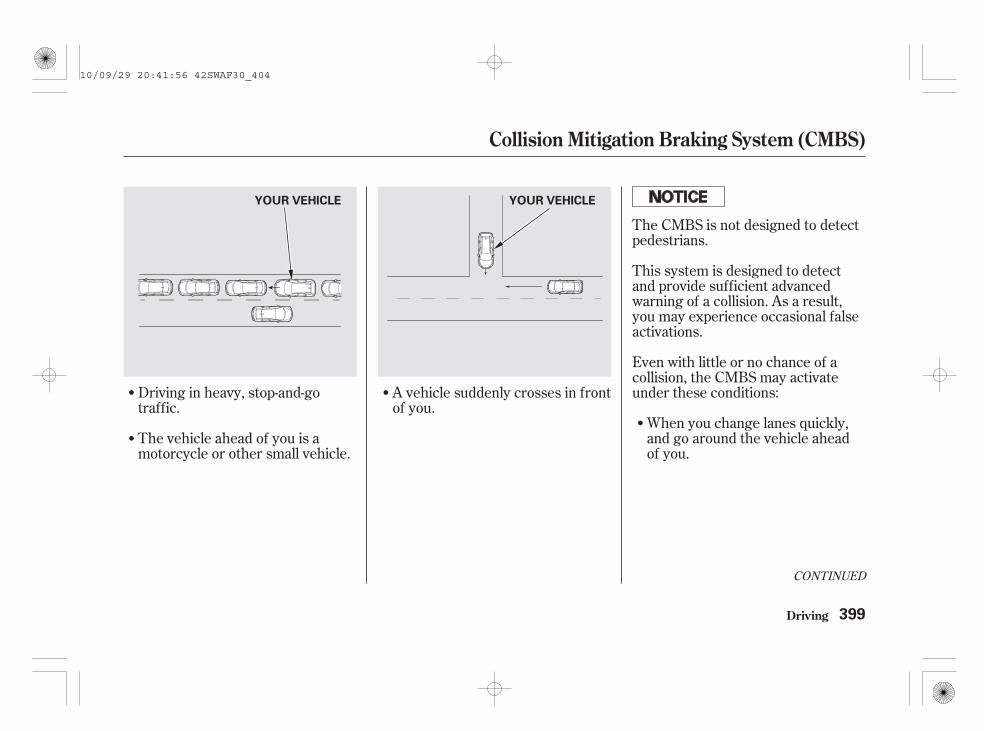
CONTINUED
The CMBS is not designed to detectpedestrians.
This system is designed to detectand provide sufficient advancedwarning of a collision. As a result,you may experience occasional falseactivations.
Even with little or no chance of acollision, the CMBS may activateunder these conditions:
When you change lanes quickly,and go around the vehicle aheadof you.
A vehicle suddenly crosses in frontof you.
Driving in heavy, stop-and-gotraffic.
The vehicle ahead of you is amotorcycle or other small vehicle.
Collision Mitigation Braking System (CMBS)
Driving 399
YOUR VEHICLEYOUR VEHICLE
10/09/29 20:41:56 42SWAF30_404

When you approach train tracks.When you pass a low bridge athigh speed.
When you go over a sharp-edgedspeed bump at high speed.
When you go over areas ofconstruction on the road surface.
When you approach or pass avehicle ahead of you that isturning left or right in anintersection.
Collision Mitigation Braking System (CMBS)
Driving400
RAILS
YOUR VEHICLE LOW BRIDGE
10/09/29 20:42:06 42SWAF30_405
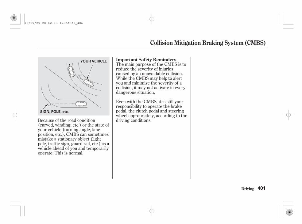
The main purpose of the CMBS is toreduce the severity of injuriescaused by an unavoidable collision.While the CMBS may help to alertyou and minimize the severity of acollision, it may not activate in everydangerous situation.
Even with the CMBS, it is still yourresponsibility to operate the brakepedal, the clutch pedal and steeringwheel appropriately, according to thedriving conditions.Because of the road condition
(curved, winding, etc.) or the state ofyour vehicle (turning angle, laneposition, etc.), CMBS can sometimesmistake a stationary object (lightpole, traffic sign, guard rail, etc.) as avehicle ahead of you and temporarilyoperate. This is normal.
Collision Mitigation Braking System (CMBS)
Driving
Important Safety Reminders
401
YOUR VEHICLE
SIGN, POLE, etc.
10/09/29 20:42:13 42SWAF30_406

The vehicle stability assist (VSA)system helps to stabilize the vehicleduring cornering if the vehicle turnsmore or less than desired. It alsoassists you in maintaining tractionwhile accelerating on loose orslippery road surfaces. It does thisby regulating the engine’s output andby selectively applying the brakes.
When VSA activates, you may noticethat the engine does not respond tothe accelerator in the same way itdoes at other times. There may alsobe some noise from the VSAhydraulic system. You will also seethe VSA activation indicator blink.
The VSA system cannot enhance thevehicle’s driving stability in allsituations and does not control yourvehicle’s entire braking system. It isstill your responsibility to drive andcorner at reasonable speeds and toleave a sufficient margin of safety.
When VSA activates, you will see theVSA Activation indicator blink.
The VSA system indicator (see page) comes on and stays on when
there is a problem with the VSAsystem. The VSA activation indicatorwill also come on.
If the VSA system indicator comeson while driving, pull to the side ofthe road when it is safe, and turn offthe engine. Reset the system byrestarting the engine. If the VSAsystem indicator stays on or comesback on while driving, have the VSAsystem inspected by your dealer.
When the VSA system indicatorcomes on, you will also see thesymbol ‘‘ ’’ or this symbol with a‘‘CHECK SYSTEM’’ message on themulti-information display.
Without VSA, your vehicle will havenormal braking and cornering ability,but it will not have VSA traction andstability enhancement.
92
VSA Activation Indicator
VSA System Indicator
Vehicle Stability Assist (VSA) System
Driving402
10/09/29 20:42:24 42SWAF30_407

This switch is under the driver’s sidevent. To turn the VSA system on andoff, press and hold it until you hear abeep.
When VSA is off, the VSA activationindicator comes on as a reminder.Press and hold the switch again. Itturns the system back on.
VSA is turned on every time youstart the engine, even if you
turned it off the last time youdrove the vehicle.
In certain unusual conditions whenyour vehicle gets stuck in shallowmud or fresh snow, it may be easierto free it with the VSA temporarilyswitched off. When the VSA systemis off, the traction control system isalso off. You should only attempt tofree your vehicle with the VSA off ifyou are not able to free it when the
VSA is on.
Immediately after freeing yourvehicle, be sure to switch the VSA onagain. We do not recommend drivingyour vehicle with the VSA andtraction control systems switched off.
Driving with varying tyre or wheelsizes may cause the VSA tomalfunction. When replacing tyres,make sure they are of the same sizeand type as your original tyres (seepage ).
If you install winter tyres, make surethey are the same size as those thatwere originally supplied with yourvehicle. Exercise the same cautionduring winter driving as you would ifyour vehicle was not equipped withVSA.
491
VSA OFF Switch
VSA and Tyre Sizes
Vehicle Stability Assist (VSA) System
Driving 403
VSA OFF SWITCH VSA OFF SWITCH
On vehicles with headlight adjusterdial
10/09/29 20:42:36 42SWAF30_408

Your vehicle is equipped with thedeflation warning system that turnson every time you start the engine.
The system monitors each wheel’srotation speed while driving over 25km/h (15 mph). If it detects adifference, the system diagnoses apossibility of a low tyre pressure.This causes the deflation warningsystem indicator in the instrumentpanel to come on.
This system cannot measure eachtyre pressure directly. You mustmanually check all tyre pressures(including the spare tyre) monthlywhen cold. Refer to page for tyreinflation guidelines.
This indicator has two functions:
When this indicator is on, one ofyour vehicle’s tyres may besignificantly underinflated. Youwill also see the symbol ‘‘ ’’ orthis symbol with a ‘‘CHECK TYREPRESSURE’’ message on themulti-information display.
You should stop and check yourtyres as soon as possible, andinflate them to the properpressures as indicated on thevehicle’s tyre information label onthe driver’s doorjamb.
If you think you can safely drive ashort distance to a service station,proceed slowly, and inflate thetyres to the recommendedpressures. Then initialise thedeflation warning system (seepage ).
If the tyre is flat, or if the tyrepressure is too low to continuedriving, replace the tyre with thecompact spare tyre (see page ).On models with a tyre repair kit, seepage to use it.
When you restart the vehicle withthe compact spare tyre, do notinitialise the system. After replacingthe compact spare tyre with thespecified regular tyre, initialise thedeflation warning system. If yourvehicle has Honda tyre repair kit,initialise the system after the flattyre is repaired with it.
1.
486
407
512
519
Deflation WarningSystem Indicator
Deflation Warning System
Driving404
10/09/29 20:42:50 42SWAF30_409
If you cannot make the deflationwarning system indicator and thesymbol/message on the multi-information go out after inflating thetyres to the specified values andinitialising the system, have yourdealer check the system as soon aspossible.
Driving on a significantly underinflated tyre causes the tyre tooverheat and can lead to tyre failure.Underinflation also reduces fuelefficiency and tyre tread life, andmay affect the vehicle’s handling andstopping ability.
Because tyre pressure varies bytemperature and other conditions,the deflation warning systemindicator may come on unexpectedly,or come on with a delay.
If there is a problem with thedeflation warning system, thisindicator begins to flash. It stopsflashing after approximately 1minute, then stays on. You willalso see the symbol ‘‘ ’’ or thissymbol with a ‘‘CHECK SYSTEM’’message on the multi-informationdisplay.
If this happens, the deflationwarning system is off and cannotdetect a low tyre pressure. Havethe system checked by your dealeras soon as possible.
This indicator may also come onalong with the ABS or VSA systemindicator as there may be a problemwith the ABS or VSA system. If thishappens, have the vehicle checkedby your dealer as soon as possible.
To activate the deflation warningsystem properly:
You should initialise the deflationwarning system once the deflationwarning system indicator comeson, or after adjusting the tyrepressures or rotating tyres (seepage ).
If the deflation warning system is notinitialised appropriately, the systemmay malfunction and the indicatormay come on unexpectedly or notcome on when needed.
Your vehicle’s tyres must be theproper type and size, in goodcondition with adequate tread, andcorrectly inflated. Refer to page
for tyre inflation.
2.
484
489
CONTINUED
Driving
Deflation Warning System
405
10/09/29 20:43:03 42SWAF30_410

The deflation warning systemindicator may also come onunexpectedly when:
A compact spare tyre is used.Snow chains are used.
A load on each tyre is significantlyunbalanced.Your tyres are overloaded, underthe severe condition such astowing a trailer.Your vehicle’s loading condition issignificantly changed from when itwas initialised.
The deflation warning systemindicator may not come on at allwhen:
Two or more tyres are deflated atthe same time.A tyre pressure drops downsuddenly and significantly.You drive on snowy or slipperyroads.The vehicle is parked.You drive under 25 km/h (15mph).
A tyre is overinflated.
Brake pedal is depressed.VSA is activated.Snow chains are used.
You accelerate or deceleraterapidly, or turn the steering wheelrapidly.
You drive at extremely high speed.
Deflation Warning System
Driving406
10/09/29 20:43:19 42SWAF30_411

You should initialise the deflationwarning system when you:
Inflate the tyres to therecommended pressure.
Change the compact spare tyre orflat tyre with the specified regulartyre.
Rotate the tyres.
Repair the flat tyre using the tyrerepair kit.
The deflation warning systemindicator and the symbol/messageon the multi-information stay on untilthe deflation warning system isinitialised.
Press and hold the INFO button toenter the customizing mode (seepage ).
Press and release the INFO buttonrepeatedly until ‘‘ ’’ isdisplayed, then press the SEL/RESET button.
To initialise the deflation warningsystem:
To initialise the deflation warningsystem, select ‘‘OK’’ by pressingthe INFO button, then press theSEL/RESET button to set.
If you want to cancel‘‘INITIALISATION,’’ select‘‘CANCEL’’ by pressing the INFObutton, then press the SEL/RESET button to set. The displaygoes back to the ‘‘ ’’ display.
1.
2.
3.
114
CONTINUED
On models with tyre repair kit
Deflation Warning SystemInitialisation
Deflation Warning System
Driving 407
10/09/29 20:43:34 42SWAF30_412

After the initialisation iscompleted, you will see the abovedisplay for a few seconds, then thedisplay goes back to the settingdisplay. At the same time, thedeflation warning system indicatorwill go off.
If the initialisation is notsuccessful, you will see the abovedisplay for a few seconds, then thedisplay goes back to the settingdisplay. Repeat from step 3.
To exit the customizing mode,select the exit mode shown aboveby pressing the INFO buttonrepeatedly, then press the SEL/RESET button. The display goesback to the normal display.
After the initialisation, drive over25 km/h (15 mph) for about 10minutes.
4. 5. 6.
7.
Deflation Warning System
Driving408
10/09/29 20:43:44 42SWAF30_413

-
Rain, fog, and snow conditions re-quire a different driving techniquebecause of reduced traction andvisibility. Keep your vehicle well-maintained and exercise greatercaution when you need to drive inbad weather. The cruise control (onsome types) should not be used inthese conditions.
Always driveslower than you would in dryweather. It takes your vehicle longerto react, even in conditions that mayseem just barely damp. Applysmooth, even pressure to all thecontrols. Abrupt steering wheelmovements or sudden, hard appli-cation of the brakes can cause loss ofcontrol in wet weather. Be extracautious for the first few kilometers(miles) of driving while you adjust tothe change in driving conditions.This is especially true in snow. Aperson can forget some snow-drivingtechniques during the summermonths. Practice is needed to relearnthose skills.
Exercise extra caution when drivingin rain after a long dry spell. Aftermonths of dry weather, the firstrains bring oil to the surface of theroadway, making it slippery.
CONTINUED
Driving Technique
Driving in Bad Weather
Driving 409
10/09/29 20:43:51 42SWAF30_414

- -Being able to seeclearly in all directions and beingvisible to other drivers are importantin all weather conditions. This ismore difficult in bad weather. To beseen more clearly during daylighthours, turn on your headlights.
Be very cautious when passing, orbeing passed by other vehicles. Thespray from large vehicles reducesyour visibility, and the wind buffetingcan cause you to lose control.
Check your tyresfrequently for wear and properpressure. Both are important inpreventing ‘‘aquaplaning’’ (loss oftraction on a wet surface). In thewinter, mount snow tyres on all fourwheels for the best handling.
Watch road conditions carefully,they can change from moment tomoment. Wet leaves can be as slip-pery as ice. ‘‘Clear’’ roads can havepatches of ice. Driving conditionscan be very hazardous when theoutside temperature is near freezing.The road surface can becomecovered with areas of water puddlesmixed with areas of ice, so yourtraction can change without warning.
Be careful when downshifting. Iftraction is low, you can lock up thedrive wheels for a moment and causea skid.
Inspect your windscreen wipers andwashers frequently. Keep the wind-screen washer reservoir full of theproper fluid. Have the windscreenwiper blades replaced if they start tostreak the windscreen or leave partsunwiped. Use the demister and airconditioning to keep the windowsfrom fogging up on the inside (seepages and ).232 239
Visibility Traction
Driving in Bad Weather
Driving410
CAUTION: Do not drive on the roadwhere water is deep. Driving throughdeep water will cause damage to theengine and electrical equipment andthe vehicle will break down.
10/09/29 20:44:00 42SWAF30_415

Your vehicle has been designedprimarily to carry passengers andtheir luggage. You can also use it totow a trailer if you carefully observethe load limits, use the properequipment, and follow the guidelinesin this section.
The total weight of the trailer andtowbar (with/without brakes) plusits luggage must not exceed themaximum towing weight. See page
.
Your vehicle is equipped with atrailer stability assist to help stabilizethe vehicle/trailer combination byreducing the vehicle speed. Formore information, see page .
Be sure to read thesection on page if you
plan to tow off paved surfaces.
Avoid towing a trailer during yourvehicle’s first 1,000 km (625 miles)(see page ).
419
352
421
571Off-Road
Guidelines
CONTINUED
Load Limits
Break-In Period
Towing a Trailer
Driving 411
Exceeding any load limit orimproperly loading yourvehicle and trailer can causea crash in which you can beseriously hurt or killed.
Check the loading of yourvehicle and trailer carefullybefore starting to drive.
10/09/29 20:44:11 42SWAF30_416

The maximum permissible weightmust not exceed the specified limitas shown on page .
The maximum permissible weightis total weight of the vehicle,driver, passengers, luggage andtowbar.
The maximum towing weightmust not exceed the specified limitas shown on page .
The trailer nose load should neverexceed 100 kg (220 lbs). This isthe amount of weight the trailerputs on the towbar when it is fully-loaded. As a rule of thumb fortrailer weights of less than 1,000kg (2,200 lbs), the trailer nose loadshould be 10 percent of the totaltrailer package.
For example, if the trailer and itsload weigh 225 kg (500 lbs), thetrailer nose load should be 22.5 kg(50 lbs). Adjust trailer’s luggage tochange the trailer nose load. Startby putting approximately60 percent of the luggage towardthe front and 40 percent towardthe rear. With a trailer package ofmore than 1,000 kg (2,200 lbs),you may need to adjust theluggage weight toward the rear.Never load the trailer so the backis heavier than the front. Thistakes weight off your vehicle’srear axle and reduces traction.
This weight will be estimated onnormal driving below 1,000 meterselevation.
If you tow a trailer in mountainousconditions, remember to reduce10% of the combined vehicle andtrailer weights from the maximumtowing weight for every 1,000meters of elevation.
The combined vehicle and trailerweights are the maximumpermissible weight and trailerweight with everything in and onthe trailer.571
571
Towing a Trailer
Driving412
10/09/29 20:44:21 42SWAF30_417

Any towbar used on your vehiclemust be properly bolted to theunderbody.
Refer to page for the towbarmounting points.
Always use safety chains when youtow a trailer. Make sure the chainsare secured to the trailer and towbar,and that they cross under the trailernose and can catch the trailer if itbecomes unhitched. Leave enoughslack to allow the trailer to turncorners easily, but do not let thechains drag on the ground.
Towing can require a variety ofequipment, depending on the size ofyour trailer, how it will be used, howmuch load you are towing, andwhere you tow.
Discuss your needs with your trailersales or rental agency, and follow theguidelines in this section. Also makesure that all equipment is properlyinstalled and maintained, and that itmeets the country’s regulationswhere you are driving.
Please consider that theinstallation of optionals (and trailernose load when towing a trailer)will reduce the loading capacity.
Towing a load that is too heavy canseriously affect your vehicle’shandling and performance. It canalso damage the engine anddrivetrain.
The best way to confirm that vehicleand trailer weights are within limitsis to have them checked at a publicscale.
Using a suitable scale or a specialtrailer nose load gauge, check thetotal weight, the weight at each axleand the trailer nose load the firsttime you set up a towing combination(a fully-loaded vehicle and trailer),then recheck the loads whenever theconditions change.
569
CONTINUED
Towbars
Safety Chains
Towing Equipment andAccessories
Checking Loads
Towing a Trailer
Driving 413
10/09/29 20:44:36 42SWAF30_418

Trailer lights and equipment mustcomply with the country’sregulations where you are driving.Check the requirements for theareas where you plan to tow, and useonly equipment designed for yourvehicle.
If you are thinking of getting a trailerthat has brakes, be sure they areelectronically actuated. Do notattempt to tap into your vehicle’shydraulic system. No matter howsuccessful it may seem, any attemptto attach trailer brakes to yourvehicle’s hydraulic system will lowerbraking effectiveness and create apotential hazard.
Your vehicle has a trailer lightingconnector located behind the leftside panel in the luggage area. Referto the drawing above for the wiringcolour code and purpose of each pin.
Since lighting and wiring vary bytrailer type and brand, you shouldhave a qualified technician install asuitable connector between thevehicle and the trailer. Improperequipment or installation can causedamage to your vehicle’s electricalsystem.
Always consult your dealer beforeconnecting the trailer lights to yourvehicle’s lighting system.
Trailer LightsTrailer Brakes
Driving
Towing a Trailer
414
HAZARD(PINK)
TRAILER(WHITE)
10/09/29 20:44:46 42SWAF30_419

There may be laws requiring specialoutside mirrors when towing a trailer.Check the local laws in the country.Even if there are no legalrequirements, you should installspecial mirrors if you cannot clearlysee behind you, or if the trailercreates a blind spot.
Ask your trailer sales or rentalagency if any other items arerecommended or required for yourtowing situation.
When preparing to tow, and beforedriving away, be sure to check thefollowing:
The vehicle has been properlyserviced, and the suspension andthe cooling system are in goodoperating condition.
The trailer has been properlyserviced and is in good condition.
All weights and loads are withinlimits.
The towbar, safety chains, and anyother attachments are secure.
All items in or on the trailer areproperly secured and cannot shiftwhile you drive.
The lights and brakes on yourvehicle and the trailer are workingproperly.
Your vehicle tyres and spare (ifequipped) are properly inflated,and the trailer tyres and spare areinflated as recommended by thetrailer maker.
Be sure to check regulationsconcerning the maximum speed ordriving restrictions for vehiclestowing trailers. If you are drivingacross several countries, checkeach country’s requirementsbefore leaving home, becauseregulations may vary.
Operating speed when towing atrailer is restricted to 100 km/h(62 mph).
Additional Trailer Equipment Pre-Tow Checklist
Towing a Trailer
Driving 415
10/09/29 20:45:00 42SWAF30_420

The added weight, length, andheight of a trailer will affect yourvehicle’s handling and performance,so driving with a trailer requiressome special driving skills andtechniques.
For your safety and the safety ofothers, take time to practice drivingmanoeuvres before heading for theopen road, and follow the guidelinesin this section.
Drive slower than normal in alldriving situations, and obey postedspeed limits for vehicles with trailers.
If your vehicle has an automatictransmission, use the D positionwhen towing a trailer on level roads.D3 is the proper shift lever positionto use when towing a trailer in hillyterrain.
Do not exceed the limited speedwhen towing a trailer. At higherspeeds, the trailer may sway oraffect vehicle handling (see ‘‘
’’ in the next page foradditional gear information).
Either shift up or shift downindicator will come on at the besttime to shift to a higher or lowergear for the better fuel economy.
The shift down indicator will notprompt to downshift to first gear. Itis up to you to downshift to first gearto increase engine braking. Avoidsudden engine braking.
Road and traffic conditions mayrequire you to shift at times otherthan those indicated.
On vehicles with manual transmissionDriving Safely With a Trailer Towing Speeds and Gears
Drivingon Hills
Towing a Trailer
Driving416
10/09/29 20:45:13 42SWAF30_421

Do not ‘‘ride’’ the brakes, andremember, it will take longer to slowdown and stop when towing a trailer.
Driving on an uphill road of morethan 12% slope is not recommendedfor your vehicle.
We recommend that you tow atrailer on the roads recommended bythe trailer association.
If you must stop when facing uphill,use the foot brake or parking brake.Do not try to hold the vehicle inplace by pressing on the accelerator,as this can cause the automatictransmission to overheat.
Make sure to set the parking brakewhen starting off on an incline.
When climbing hills, closely watchyour temperature gauge. If it nearsthe red (Hot) mark, turn the airconditioning off, reduce speed and, ifnecessary, pull to the side of theroad to let the engine cool.
When driving down hills, reduceyour speed and always apply enginebraking by shifting down. If yourvehicle has a manual transmission,when going down a steep hill, usethe 3rd gear to provide greaterengine braking.
If your vehicle has an automatictransmission, when driving downhills, reduce your speed and use theD3 position. When going down asteep hill, use the 2nd position toprovide greater engine braking.
Make turns more slowly and widerthan normal. The trailer tracks asmaller arc than your vehicle, and itcan hit or run over something thevehicle misses. Allow more time anddistance for braking. Do not brake orturn suddenly as this could cause thetrailer to jackknife or turn over.
CONTINUED
Driving on HillsMaking Turns and Braking
Towing a Trailer
Driving 417
10/09/29 20:45:25 42SWAF30_422

You should keep the engine idlingfor about 2 minutes before turningoff the ignition switch. (Idling theengine is prohibited in somecountries. Always follow the legalrequirements of the countries inwhich you will drive.)
Always drive slowly and havesomeone guide you when backing up.Grip the of the steering wheel,then turn the wheel to the left to getthe trailer to move to the left, andturn the wheel right to move thetrailer to the right.
Follow all normal precautions whenparking, including firmly setting theparking brake and putting thetransmission in Park (automatic) orin first or reverse (manual). Also,place wheel chocks at each of thetrailer’s tyres.
Crosswinds and air turbulencecaused by passing trucks can disruptyour steering and cause the trailer tosway. When being passed by a largevehicle, keep a constant speed, andsteer straight ahead. Do not try tomake quick steering or brakingcorrections.
bottom
On Diesel models onlyBacking Up
Parking
Handling Crosswinds and Buffeting
Towing a Trailer
Driving418
10/09/29 20:45:34 42SWAF30_423

Your vehicle is equipped with thetrailer stability assist function. Thisfunction works on the same sensorsas the vehicle stability assist (VSA)system. This function helps tostabilize the vehicle/trailercombination when the trailerseverely sways or oscillates. Formore information of the VSA system,see page .
If the function detects the vehicle/trailer instability, it checks if theswaying is caused by the trailer, andif the trailer swaying or oscillation isincreasing.
Under these conditions, trailerstability assist begins to stabilize thevehicle/trailer combination byreducing the vehicle speed. Thecontrol unit sends signals toselectively apply the brakes andregulate the engine output. Thebrake lights of your vehicle will beturned on automatically by thesystem even if you do not keep thepressure on the brake pedal.
Trailer stability assist cannot preventa loss of control. Always reduce thevehicle speed and steer firmly. Donot brake suddenly or make quicksteering motion. It could cause thetrailer to jackknife or turn over andthe system becomes ineffective.
Trailer stability assist will also beineffective while driving at highspeed or towing a trailer with a highcentre of gravity.
Trailer stability assist cannot preventswaying that can occur in crosswindsand in normal and emergencydriving manoeuvres. It helps only tostabilize the vehicle/trailercombination in these conditions,after the oscillation becomes severe.
When the brakes are applied, thetrailer’s brake lights come on alongwith the vehicle brake lights.
When the trailer stability assistactivates, you will see the VSAactivation indicator blink. There mayalso be some noise from the VSAhydraulic system.
Always obey the speed limits fortowing a trailer, see page .
The vehicle/trailer combination ismore affected by crosswinds,buffeting, and improper trailer noseload. These conditions can make thetrailer unstable, and cause it to sway.
402
415
Trailer Stability Assist
Driving 419
10/09/29 20:45:46 42SWAF30_424

The control unit monitors the VSAcircuitry and the braking system. Ifthere is a problem with the brakelighting system, the trailer stabilityassist function shuts down, and thesymbol ‘‘TSA ’’ or this symbol witha ‘‘CHECK SYSTEM’’ messageappears on the multi-informationdisplay.
If you see this message, have yourvehicle checked at your dealer assoon as possible.
In this case, your vehicle still has theVSA traction and stabilityenhancement, but it will not have thetrailer stability assist function.
If there is a problem with the VSAsystem, the VSA system and trailerstability assist function shut off, anda symbol ‘‘VSA’’ or this symbol witha ‘‘CHECK SYSTEM’’ message andthen a symbol ‘‘TSA ’’ or thissymbol with a ‘‘CHECK SYSTEM’’message appear on the multi-information display. The VSA systemand VSA activation indicators alsocome on (see page ).
The ABS indicator and the brakesystem indicator may also come onalong with the VSA system indicator.
If you see these warning indicators,have your vehicle checked at yourdealer as soon as possible.
If you turn off the VSA, the trailerstability assist function also shuts off.Press and hold the VSA off switchuntil you hear a beep (see page ).The VSA activation indicator comeson as a reminder. Press and hold theswitch again to turn the system on.
The function turns on every time youstart the engine along with the VSA,even if you turned it off the last timeyou drove the vehicle.402
403
Trailer Stability Assist Failure
Trailer Stability Assist
Driving420
TM
TM
10/09/29 20:45:57 42SWAF30_425
Your vehicle has been designedprimarily for use on paved roads. Butits higher ground clearance allowsyou to occasionally travel on unpavedroads, such as campgrounds, picnicsites, and similar locations. It is notdesigned for trail-blazing, mountainclimbing, or other challenging off-road activities.
If you decide to drive on unpavedroads, you will find that it requiressomewhat different driving skills.Your vehicle will also handlesomewhat differently than it does onpaved roads. So be sure to read thisowner’s manual, pay special attentionto the precautions and tips in thissection, and get acquainted withyour vehicle before you leave thepaved roads.
In many countries, the law prohibitsoff-road driving, e.g. driving inforests, trailblazing, etc. Pleasecheck your local laws andregulations before commencing anyoff-road driving activity.
General Information
Off-Road Guidelines
Driving 421
Improperly operating thisvehicle on or off pavementcan cause a crash or rolloverin which you and yourpassengers could beseriously injured or killed.
Follow all instructions andguidelines in this owner’smanual.Keep your speed low, anddon’t drive faster thanconditions permit.
10/09/29 20:46:05 42SWAF30_426

For better traction on all surfaces,accelerate slowly and gradually buildup speed. If you try to start too faston wet soil, mud, snow, or ice, youmight not have enough traction toget underway, and you may digyourself a hole. Starting with theshift lever in second (2) gear willhelp you have a smoother start onsnow or ice.
Keep in mind that you will usuallyneed more time and distance tobrake to a stop on unpaved surfaces.Avoid hard braking. Do not ‘‘pump’’the brakes; let the anti-lock brakingsystem pump them for you.
Before you leave the paved road, besure to do all scheduled maintenanceand service, and inspect your vehiclefor any problems. Pay specialattention to the condition of the tyres,and check the tyre pressures.
After you return to the paved road,carefully inspect your vehicle tomake sure there is no damage thatcould make driving it unsafe.Recheck the condition of the tyresand the tyre pressures.
The route presents limits (too steepor bumpy roads). You have limits(driving skill and comfort). And yourvehicle has limits (traction, stability,and power).
Driving off-road can be hazardous ifyou fail to recognize limits and takethe proper precautions.
To avoid loss of control or rollover,be sure to follow all precautions andrecommendations.
Be sure to store luggage properly,and do not exceed your vehicleluggage load limits (see pages
and ).
Whenever you drive, make sureyou and your passengers alwayswear seat belts.
Keep your speed low, and nevergo faster than the conditions allow.
It’s up to you to continually assessthe situation and drive within thelimits.
366 571
Accelerating and BrakingCheck Out Your Vehicle
Remember
Important Safety Precautions
Off-Road Guidelines
Driving422
10/09/29 20:46:20 42SWAF30_427
Avoid driving on soft sand, deep mud,or other surfaces where you couldget stuck. If you do happen to getstuck because of inclement weatheror other conditions, choose a safeand appropriate course of action.
You should never use a jack to trygetting unstuck. A jack only workson firm, level ground. Also, yourvehicle could easily slip off the jackand hurt you or someone else.
Avoid driving through deep water. Ifyou encounter water in your route (asmall stream or large puddle, forexample), evaluate it carefully beforegoing ahead. Make sure it is shallow,flowing slowly, and has firm groundunderneath. If you are not sure ofthe depth or the ground, turn aroundand find another route.
Driving through deep water can alsodamage your vehicle. The water canget into the transmission anddifferential, diluting the lubricantand causing an eventual failure. Itcan also wash the grease out of thewheel bearings.
Debris in the road can damage yoursuspension or other components.Because your vehicle has a highcentre of gravity, driving over a largeobstacle, or allowing a wheel to dropinto a deep hole can cause yourvehicle to tip or roll over.
If you can’t clearly see all conditionsor obstacles on a slope, walk theslope before you drive on it. If youhave any doubt whether or not youcan safely drive on the slope, don’tdo it. Find another route.
If you are driving up a hill and findthat you cannot continue,
. Your vehicle could rollover. Slowly back down the hill,following the same route you took upthe hill.
do not try toturn around
If You Get StuckCrossing a StreamAvoiding Obstacles
Driving on Slopes
Driving
Off-Road Guidelines
423
10/09/29 20:46:31 42SWAF30_428

If you spin the wheels excessivelytrying to get unstuck, you mayoverheat the components of the4-wheel drive system. If this happens,the 4-wheel drive system shuts offand only the front wheels receivepower. If this happens, stop andallow everything to cool down. The4-wheel drive system will work againafter its temperature drops.
If you slip the clutch for a long timewhile trying to get unstuck, you mayoverheat and damage it.
Off-Road Guidelines
Driving424
10/09/29 20:46:36 42SWAF30_429

Regularly maintaining your vehicle isthe best way to protect your invest-ment. You will be rewarded withsafer, more economical, trouble-freedriving. This section lists items thatneed to be checked regularly andexplains how to check them. It alsodetails some simple maintenancetasks you can do yourself. Themaintenance schedules show youwhen these things need to be done.
......................Maintenance Safety . 426.................Maintenance Schedule . 427
....................Maintenance Record . 437..............................Fluid Locations . 439
Adding Engine Oil.........................(Petrol models) . 442
Adding Engine Oil.........................(Diesel models) . 444
Engine Coolant.........................(Petrol models) . 446
Engine Coolant.........................(Diesel models) . 448
...................Windscreen Washers . 450....Automatic Transmission Fluid . 451
........Manual Transmission Fluid . 453.................Rear Differential Fluid . 454
.............Transfer Assembly Fluid . 454................Brake and Clutch Fluid . 454
....................Power Steering Fluid . 456Air Cleaner Element
.........................(Petrol models) . 457Air Cleaner Element
.........................(Diesel models) . 460......................................Fuel Filter . 462
.............................................Lights . 463..............Air Conditioning System . 479
..................Dust and Pollen Filter . 480.................................Wiper Blades . 482
..............................................Tyres . 486...................Checking the Battery . 495...................Replacing the Battery . 497
.............................Vehicle Storage . 499Priming the Fuel System
....................(Diesel models) . 501
Maintenance
Maintenance
425
10/09/29 20:46:41 42SWAF30_430

To eliminate potential hazards, readthe instructions before you begin,and make sure you have the toolsand skills required.
Make sure your vehicle is parkedon level ground, the parking brakeis set, and the engine is off.
To reduce the possibility of fire orexplosion, keep cigarettes, sparks,and flames away from the batteryand all fuel-related parts.
Wear eye protection andprotective clothing when workingwith the battery or compressed air.
Be sure there isadequate ventilation whenever youoperate the engine.
Let theengine and exhaust system cooldown before touching any parts.
Donot run the engine unlessinstructed to do so.
Some of the most important safetyprecautions are given here. However,we cannot warn you of everyconceivable hazard that can arise inperforming maintenance. Only youcan decide whether or not youshould perform a given task.
All service items not detailed in thissection should be performed by acertified technician or other qualifiedtechnician.
To clean parts, use a commerciallyavailable degreaser or partscleaner, not fuel.
Maintenance Safety
Important Safety Precautions
Potential Vehicle HazardsCarbon Monoxide poison fromengine exhaust.
Burns from hot parts.
Injury from moving parts.
Maintenance426
Failure to properly followmaintenance instructionsand precautions can causeyou to be seriously hurt orkilled.
Always follow theprocedures and precautionsin this owner’s manual.
Improperly maintaining thisvehicle or failing to correct aproblem before driving cancause a crash in which youcan be seriously hurt or killed.
Always follow the inspectionand maintenancerecommendations andschedules in this owner’smanual/Service Book.
10/09/29 20:46:55 42SWAF30_431

-
The required maintenance schedulespecifies all maintenance required tokeep your vehicle in peak operatingcondition. Maintenance work shouldbe performed in accordance with thestandards and specifications ofHonda by properly trained andequipped technicians. Yourauthorized dealer meets all of theserequirements.
Do not press the engine coverforcibly. This may damage theengine cover and component parts.
We recommend the use of genuineHonda parts and fluids or theirequivalent whenever you havemaintenance done. These are thesame high-quality items that wentinto your vehicle when it was new, soyou can be sure they fit and performflawlessly.
Always use the recommendeddiesel fuel only (see page ).
Always use the recommendedpetrol only (see page ).
In South Africa, follow themaintenance schedule in themaintenance booklet that came withyour vehicle.
Drive your vehicle regularly over adistance of several kilometers(miles).
Operate your vehicle onreasonable roads within the legalspeed limit.
Avoid exceeding your vehicle’sload limit. This puts excess stresson the engine, brakes, and manyother vehicle parts.
The maintenance schedule assumesyou will use your vehicle as normaltransportation for passengers andtheir possessions. You should alsofollow these recommendations:
The maintenance schedule in thisowner’s manual should be appliedexcept for EU and South Africa (seepages to ).
In EU countries, follow themaintenance schedule in the ServiceBook that came with your vehicle.
There are two types of maintenanceschedule in this owner’s manual. Oneis for petrol models (see pages to
), and the other is for dieselmodels (see pages ).
429433
434 436
429 436
352
353
On Diesel models
On Diesel models
On Petrol models
Maintenance Schedule
Maintenance 427
10/09/29 20:47:11 42SWAF30_432

-
-
-
- -
-
-
-
-
-
-
-
-
-
-
You should check the followingitems at the use or specified intervals.
Engine oil level Check everytime you fill the fuel tank. Seepage .
Engine coolant level
Check the radiator reserve tankevery time you fill the fuel tank.See page .
Check the expansion tank everytime you fill the fuel tank. Seepage .
Windscreen washer fluid Checkthe level in the reservoir monthly.If weather conditions cause you touse the washers frequently, checkthe reservoir each time you stopfor fuel. See page .
Windscreen wipers Check thewiper condition monthly. If thewipers do not wipe the windscreensecurely, check them for wear,cracks, and other damage.
Battery Check its condition andthe terminals for corrosionmonthly. See page .
Parking brake Check theparking brake lever for smoothoperation.
Brake pedal Check the brakepedal for smooth operation.
Brakes and clutch Check thefluid level monthly. See page .
Automatic transmission Checkthe fluid level monthly. See page
.
Air conditioning system Checkits operation weekly. See page .
Windscreen demister Operatethe heater and air conditioningand check the demister ventsmonthly.
Lights Check the operation ofthe headlights, position lights, tail-lights, high-mount brake light, andlicence plate lights monthly. Seepage .
Doors Check the tailgate andall doors including the rear doorsfor smooth opening/closing andsecure locking.
Horn Check the horn operation.
Tyres Check the tyre pressuremonthly, then initialise thedeflation warning system.Examine the tread for wear andforeign objects. See page .
357
360
360
450
451
454
486
495
479
463
On Petrol models
On Diesel models
Maintenance Schedule
Owner’s Maintenance Checks
Maintenance428
10/09/29 20:47:30 42SWAF30_433

-
***
*
*
*
*
*
CONTINUED
This maintenance scheduleoutlines the minimum requiredmaintenance that you shouldperform to ensure the trouble-free operation of your vehicle.Due to regional and climaticdifferences, some additionalservicing may be required.Please consult your warrantybooklet for a more detaileddescription.
Maintenance
Maintenance Schedule for Petrol Models (Except EU, Russia, Ukraine, and South Africa models)
429
MA
IN
TE
NA
NC
ES
CH
ED
UL
E
Service at the indicated distanceor time whichever comes first.
km x 1,000miles x 1,000months
Every 100,000 km (62,500 miles)
Every 40,000 km (25,000 miles)Every 20,000 km (12,500 miles)Every 10,000 km (6,250 miles)
6037.536
14087.584
180112.5108
Every 5,000 km (3,125 miles) or 6 months
Every 10,000 km (6,250 miles) or 6 months
Every 10,000 km (6,250 miles) or 1 year
2012.512
4025.024
8050.048
10062.560
12075.072
160100.0
96
200125.0120
Only severe schedule is required in some countries: refer to the local warranty booklet that came with your vehicle.Refer to page for replacement information under severe conditions.Refer to page for replacement information under severe driving conditions.
At 200,000 km (120,000 miles) or 10 years, thereafterevery 100,000 km (60,000 miles) or 5 years
Replace engine oil
Replace engine oil filter
Clean air cleaner element (Dry type only)Replace air cleaner elementInspect valve clearanceReplace fuel filterReplace spark plugsInspect drive beltInspect idle speedReplace engine coolant
Iridium type
NormalSevereNormalSevere
1 :2 :3 :
431462
1
1
3
2
2
10/09/29 20:47:53 42SWAF30_434

-
*
*
Maintenance
Maintenance Schedule for Petrol Models (Except EU, Russia, Ukraine, and South Africa models)
430
Visually inspect the following items:
MA
IN
TE
NA
NC
ES
CH
ED
UL
E
Service at the indicated distanceor time whichever comes first.
km x 1,000miles x 1,000months
Rotate tyres every 10,000 km (6,250 miles)
Every 10,000 km (6,250 miles) or 6 months
Every 3 years (independent of distance)
4025.024
14087.584
6037.536
2012.512
8050.048
10062.560
12075.072
160100.0
96
180112.5108
Every 10,000 km (6,250 miles) or 6 months
200125.0120
Refer to page for replacement information under severe conditions.
Replace transmission fluid
Replace rear differential fluidInspect front and rear brakesReplace brake fluidCheck parking brake adjustmentReplace dust and pollen filterCheck expiry date for TRK bottle (if equipped)Rotate tyres (Check tyre inflation and condition atleast once per month)
Tie rod ends, steering gear box and bootsSuspension componentsDriveshaft bootsBrake hoses and lines (including ABS/VSA)All fluid levels and condition of fluidsExhaust systemFuel lines and connections
NormalSevereNormalSevere
M/T
A/T
: 431
10/09/29 20:48:11 42SWAF30_435

If you drive your vehicle under one or more of the following severeconditions, the following items must be serviced according to themaintenance schedule indicated as Severe.
Extensive idling or long periods of stop-and-go driving.Trailer towing, driving with a loaded roof rack, or driving in mountainousconditions.Driving on muddy, dusty, or de-iced roads.
Condition
A, B, C, D, E
B, D,
Items
Engine oil and oil filter
Transmission fluid(M/T, A/T)
Driving less than 8 km per trip, or in freezing temperatures, driving lessthan 16 km per trip.Driving in extremely hot (over 35°C) conditions.
A:
B:C:D:
E:
NOTE:
Severe driving conditions:
Maintenance
Maintenance Schedule for Petrol Models (Except EU, Russia, Ukraine, and South Africa models)
431
MA
IN
TE
NA
NC
ES
CH
ED
UL
E
10/09/29 20:48:22 42SWAF30_436

-
**
*
*
*
*
This maintenanceschedule outlinesthe minimumrequiredmaintenance thatyou shouldperform to ensurethe trouble-freeoperation of yourvehicle. Due toregional andclimaticdifferences, someadditionalservicing may berequired. Pleaseconsult yourwarranty bookletfor a more detaileddescription.
Maintenance
Maintenance Schedule for Petrol Models (Russia and Ukraine models)
432
Visually inspect the following items:
MA
IN
TE
NA
NC
ES
CH
ED
UL
E
Service at the indicated distanceor time whichever comes first.
km x 1,000months
1512
3024
4536
6048
7560
9072
Every 7,500 km or 6 months
10584
12096
135108
150120
165132
180144
195156
Every 120,000 km
Every 30,000 kmEvery 15,000 km
When you drive primarily in urban areas that have high concentrations of soot in the air, under dusty conditions or the airflow fromthe climate control system becomes less than usual. Replace the filter every 15,000 km or 1 year.
Refer to page for replacement information under severe driving conditions.Refer to page for replacement information under severe conditions.
Replace engine oil and oil filter
Clean air cleaner elementReplace air cleaner elementInspect valve clearanceReplace fuel filterReplace spark plugsInspect drive beltInspect idle speedReplace engine coolantReplace transmission fluidReplace rear differential fluidInspect front and rear brakesReplace brake fluidCheck parking brake adjustmentReplace dust and pollen filter (if equipped)Check lights alignmentTest drive (noise, stability, dashboard operation)Inspect vehicle corrosion
Tie rod ends, steering gear box, and bootsSuspension componentsDriveshaft bootsBrake hoses and lines (including ABS/VSA)All fluid levels and condition of fluidsExhaust systemFuel lines and connectionsTyre condition
At 200,000 km or 10 years, thereafter every 100,000 km or 5 years
Every 3 years (independent of distance)
A/T
Dry type only
1 :3 :
2 :
NormalSevere
433 462
2
3
1
10/09/29 20:48:47 42SWAF30_437

If you drive your vehicle under one or more of the following severeconditions, the following items must be serviced according to themaintenance schedule indicated as Severe.
Extensive idling or long periods of stop-and-go driving.Trailer towing, driving with a loaded roof rack, or driving in mountainousconditions.Driving on muddy, dusty, or de-iced roads.
Condition
A, B, C, D, E
Items
Engine oil and oil filter
Driving less than 8 km per trip, or in freezing temperatures, driving lessthan 16 km per trip.Driving in extremely hot (over 35°C) conditions.
A:
B:C:D:
E:
NOTE:
Severe driving conditions:
Maintenance
Maintenance Schedule for Petrol Models (Russia and Ukraine models)
433
MA
IN
TE
NA
NC
ES
CH
ED
UL
E
10/09/29 20:48:56 42SWAF30_438

-
*
*
*
*
*
This maintenance scheduleoutlines the minimum requiredmaintenance that you shouldperform to ensure the trouble-free operation of your vehicle.Due to regional and climaticdifferences, some additionalservicing may be required.Please consult your warrantybooklet for a more detaileddescription.
Maintenance
Maintenance Schedule for Diesel Models (Except EU and South Africa)
434
MA
IN
TE
NA
NC
ES
CH
ED
UL
E
Service at the indicated distanceor time whichever comes first.
km x 1,000miles x 1,000months
Every 5,000 km (3,125 miles) or 6 monthsEvery 30,000 km (18,750 miles)
4025.024
8050.048
At 100,000 km (62,500 miles) or 5 years, thereafter every60,000 km (37,500 miles) or 3 years
14087.584
160100.0
96
200125.0120
2012.512
Every 10,000 km (6,250 miles) or 1 year
6037.536
10062.560
12075.072
180112.5108
Every 120,000 km (75,000 miles) or 6 yearsEvery 60,000 km (37,500 miles) or 3 years
At 120,000 km (75,000 miles) or 6 years, thereafter every80,000 km (50,000 miles) or 4 years
At 60,000 km (37,500 miles) or 3 years, thereafter every40,000 km (25,000 miles) or 2 years
At 120,000 km (75,000 miles) or 6 years, thereafter every80,000 km (50,000 miles) or 4 years
At 60,000 km (37,500 miles) or 3 years, thereafter every40,000 km (25,000 miles) or 2 years
Every 10,000 km (6,250 miles) or 6 months
At 20,000 km (12,500 miles) or 1 year, thereafter every80,000 km (50,000 miles) or 4 years
Refer to page for replacement information under severe conditions.
Replace engine oil and oil filter
Replace air cleaner elementReplace fuel filterInspect drive beltReplace engine coolant
Replace transmission fluid
Replace transfer fluid
Replace rear differential fluid
Inspect front and rear brakes
NormalSevere
:
NormalSevereNormal
Severe
Normal
Severe
M/T
A/T
AT only
436
10/09/29 20:49:20 42SWAF30_439

-
CONTINUED
Maintenance
Maintenance Schedule for Diesel Models (Except EU and South Africa)
435
Visually inspect the following items:
MA
IN
TE
NA
NC
ES
CH
ED
UL
E
Service at the indicated distanceor time whichever comes first.
km x 1,000miles x 1,000months
Every 3 years (independent of distance)
2012.512
4025.024
6037.536
8050.048
10062.560
12075.072
14087.584
160100.0
96
180112.5108
200125.0120
Rotate tyres every 10,000 km (6,250 miles)
Every 10,000 km (6,250 miles) or 6 months
Replace brake fluidCheck parking brake adjustmentReplace dust and pollen filter (if equipped)Check expiry date for TRK bottle (if equipped)Rotate tyres (Check tyre inflation and condition atleast once per month)
Tie rod ends, steering gear box and bootsSuspension componentsDriveshaft bootsBrake hoses and lines (including ABS/VSA)All fluid levels and condition of fluidsExhaust systemFuel lines and connections
10/09/29 20:49:35 42SWAF30_440

If you drive your vehicle under one or more of the following severeconditions, the following items must be serviced according to themaintenance schedule indicated as Severe.
Extensive idling or long periods of stop-and-go driving.Trailer towing, driving with a loaded roof rack, or driving in mountainousconditions.Driving on muddy, dusty, or de-iced roads.
Driving in extremely hot (over 35°C) conditions.
Driving less than 8 km per trip, or in freezing temperatures, driving lessthan 16 km per trip.
Condition
A, B, C, D, E
D, E
B, D
B, D
Items
Engine oil and oil filter
Air cleaner element
Transmission fluid(M/T, A/T)
Transfer fluid
A:
B:C:D:
E:
Maintenance
NOTE:
Severe driving conditions:
Maintenance Schedule for Diesel Models (Except EU and South Africa)
436
MA
IN
TE
NA
NC
ES
CH
ED
UL
E
10/09/29 20:49:46 42SWAF30_441

Have your servicing dealer record all required maintenance below. Keep receipts for all work done on your vehicle.
12,500 Mi.(or 12 Mo.)
25,000 Mi.(or 24 Mo.)
37,500 Mi.(or 36 Mo.)
50,000 Mi.(or 48 Mo.)
62,500 Mi.(or 60 Mo.)
(Sign or Stamp)
(Sign or Stamp)
(Sign or Stamp)
(Sign or Stamp)
(Sign or Stamp)
Km (Mi.) or Month
Date
Km (Mi.) or Month
Date
Km (Mi.) or Month
Date
Km (Mi.) or Month
Date
Km (Mi.) or Month
Date
75,000 Mi.(or 72 Mo.)
87,500 Mi.(or 84 Mo.)
100,000 Mi.(or 96 Mo.)
112,500 Mi.(or 108 Mo.)
125,000 Mi.(or 120 Mo.)
(Sign or Stamp)
(Sign or Stamp)
(Sign or Stamp)
(Sign or Stamp)
(Sign or Stamp)
Km (Mi.) or Month
Date
Km (Mi.) or Month
Date
Km (Mi.) or Month
Date
Km (Mi.) or Month
Date
Km (Mi.) or Month
Date
20,000 km
40,000 km
60,000 km
80,000 km
100,000 km
120,000 km
140,000 km
160,000 km
180,000 km
200,000 km
Maintenance
Maintenance Record (Except EU, Russia, Ukraine and South Africa models)
437
10/09/29 20:49:54 42SWAF30_442

(or 12 Mo.)
(or 24 Mo.)
(or 36 Mo.)
(or 48 Mo.)
(or 60 Mo.)
(or 72 Mo.)
(or 84 Mo.)
(Sign or Stamp)
(Sign or Stamp)
(Sign or Stamp)
(Sign or Stamp)
(Sign or Stamp)
(Sign or Stamp)
(Sign or Stamp)
Km or Month
Date
Km or Month
Date
Km or Month
Date
Km or Month
Date
Km or Month
Date
Km or Month
Date
Km or Month
Date
(or 96 Mo.)
(or 108 Mo.)
(or 120 Mo.)
(or 132 Mo.)
(or 144 Mo.)
(or 156 Mo.)
(Sign or Stamp)
(Sign or Stamp)
(Sign or Stamp)
(Sign or Stamp)
(Sign or Stamp)
(Sign or Stamp)
Km or Month
Date
Km or Month
Date
Km or Month
Date
Km or Month
Date
Km or Month
Date
Km or Month
Date
Have your servicing dealer record all required maintenance below. Keep receipts for all work done on your vehicle.
Maintenance
15,000 km
30,000 km
45,000 km
60,000 km
75,000 km
90,000 km
105,000 km
120,000 km
135,000 km
150,000 km
165,000 km
180,000 km
195,000 km
Maintenance Record (Russia and Ukraine models)
438
10/09/29 20:50:03 42SWAF30_443

CONTINUED
Fluid Locations (Petrol models)
Maintenance 439
WASHER FLUID(Blue cap)
ENGINE OIL FILL CAP
AUTOMATICTRANSMISSIONFLUID DIPSTICK(Yellow loop)
BRAKE FLUID(Black cap)
ENGINE OIL DIPSTICK(Orange handle)
ENGINE COOLANT RESERVOIRRADIATOR CAP
2.0 engine model
Left-hand drive type is shown.
CLUTCH FLUID(ManualTransmission only)(Light grey cap)
10/09/29 20:50:09 42SWAF30_444

Fluid Locations (Petrol models)
Maintenance440
AUTOMATICTRANSMISSIONFLUID DIPSTICK(Yellow loop)
2.4 engine model
CLUTCH FLUID(ManualTransmission only)(Light gray cap)
Left-hand drive type is shown.
ENGINE COOLANT RESERVOIR
POWER STEERING FLUID(Red cap)
ENGINE OIL FILL CAP
RADIATOR CAPENGINE OIL DIPSTICK(Orange handle)
WASHER FLUID(Blue cap)
BRAKE FLUID(Black cap)
10/09/29 20:50:15 42SWAF30_445

Fluid Locations (Diesel models)
Maintenance 441
ENGINE OIL DIPSTICK(Orange handle)
BRAKE FLUID(Black cap)
ENGINE OIL FILL CAP
CLUTCH FLUID(ManualTransmission only)(Light grey cap)
Left-hand drive type is shown.
AUTOMATICTRANSMISSIONFLUID DIPSTICK(Yellow loop)
EXPANSION TANK
WASHER FLUID(Blue cap)
POWER STEERING FLUID(Red cap)
10/09/29 20:50:20 42SWAF30_446

Unscrew and remove the engine oilfill cap on the valve cover. Pour theoil slowly and carefully so you do notspill any. Clean up any spillsimmediately. Spilled oil coulddamage components in the enginecompartment.
Reinstall the engine oil fill cap, andtighten it securely. Let the enginewarm up and turn off the engine, letit sit for approximately 3 minutes,then check the oil level on theengine oil dipstick. Do not fill abovethe upper mark; you could damagethe engine.
This oil is formulated to help yourengine use less fuel.
Oil is a major contributor to yourengine’s performance and longevity.Always use a premium-gradedetergent oil. It is highlyrecommended that you use genuineHonda Motor Oil, ‘‘ACEA A1/B1,’’‘‘ACEA A3/B3,’’ or ‘‘ACEA A5/B5’’in your vehicle for as long as youown it.
Recommended Engine OilEuropean models
Adding Engine Oil (Petrol models)
Maintenance442
ENGINE OIL FILL CAP ENGINE OIL FILL CAP
2.0 engine model 2.4 engine model
10/09/29 20:50:29 42SWAF30_447

*You can select the proper SAE/ACEA viscosity oil for your vehicleaccording to this chart:
Oil is a major contributor to yourengine’s performance and longevity.Always use a premium-grade deter-gent oil. It is highly recommendedthat you use genuine Honda MotorOil in your vehicle for as long as youown it.
You can select the proper SAEviscosity oil for your vehicleaccording to this chart:
0W-20 oil is formulated to help yourengine use less fuel.
0W-30 oil is formulated to help yourengine use less fuel.
Always use an API service SL orhigher grade fuel-efficient oil. Thisoil is formulated to help your engineuse less fuel.
Your vehicle does not require any oiladditives. Additives may adverselyaffect your engine’s or transmission’sperformance and durability.
Except for vehicles with oil levelsensor
:Except for European models
Adding Engine Oil (Petrol models)
Maintenance
Engine Oil Additives
443
Ambient Temperature
Ambient Temperature
10/09/29 20:50:41 42SWAF30_448

Unscrew and remove the engine oilfill cap on the valve cover. Pour theoil slowly and carefully so you do notspill any. Clean up any spillsimmediately. Spilled oil coulddamage components in the enginecompartment.
Always use a synthetic motor oil thatmeets the ACEA specifications, andis the proper viscosity as shown inthe following chart. When usingsynthetic oil, you must follow the oiland filter change intervals shown bythe maintenance schedule.
Reinstall the engine oil fill cap, andtighten it securely. Let the enginewarm up and turn off the engine, letit sit for approximately 3 minutes,then check the oil level on theengine oil dipstick. Do not fill abovethe upper mark; you could damagethe engine.
Recommended Engine Oil
Adding Engine Oil (Diesel models)
Maintenance444
ENGINE OIL FILL CAP
10/09/29 20:50:48 42SWAF30_449

It is highly recommended that youuse genuine Honda Motor Oil or0W-30 synthetic motor oil meetingthe specification: ‘‘ACEA C2’’ or‘‘ACEA C3.’’
You can select the proper SAE/ACEA viscosity oil for your vehicleaccording to this chart:
NOTE: 0W-30 is formulated toimprove fuel economy.
Your vehicle does not require any oiladditives. Additives may adverselyaffect the engine or transmissionperformance and durability.
Adding Engine Oil (Diesel models)
Maintenance
Engine Oil Additives
445
Ambient Temperature
10/09/29 20:50:55 42SWAF30_450

The cooling system contains manyaluminium components that cancorrode if an improper antifreeze isused. Some antifreeze, even thoughlabelled as safe for aluminium parts,may not provide adequate protection.
If the reserve tank is completelyempty, you should also check thecoolant level in the radiator.
If the coolant level in the reservetank is at or below the MIN line, addcoolant to bring it up to the MAX line.Inspect the cooling system for leaks.
Always use genuine Honda AllSeason Antifreeze/Coolant Type 2.This coolant is pre-mixed with 50percent antifreeze and 50 percentdistilled water. Never add straightantifreeze or plain water.
Adding Engine Coolant
Engine Coolant (Petrol models)
Maintenance446
Removing the radiator capwhile the engine is hot cancause the coolant to sprayout, seriously scalding you.
Always let the engine andradiator cool down beforeremoving the radiator cap.
RESERVE TANKMAX
MIN2.4 engine model is shown.
10/09/29 20:51:04 42SWAF30_451

The coolant level should be up tothe base of the filler neck. Addcoolant if it is low.
Pour the coolant slowly andcarefully so you do not spill any.Clean up any spills immediately; itcould damage components in theengine compartment.
Put the radiator cap back on, andtighten it fully.
Make sure the engine and radiatorare cool.
Relieve any pressure in the coolingsystem by turning the radiator capanticlockwise, without pressingdown.
Remove the radiator cap bypushing down and turninganticlockwise.
Pour coolant into the reserve tank.Fill it to halfway between the MAXand MIN marks. Put the cap backon the reserve tank.
Do not add any rust inhibitors orother additives to your vehicle’scooling system. They may not becompatible with the coolant orengine components.
4.
5.
6.1.
2.
3.
Engine Coolant (Petrol models)
Maintenance 447
RADIATOR CAP
RESERVE TANK
2.4 engine model is shown.
10/09/29 20:51:15 42SWAF30_452
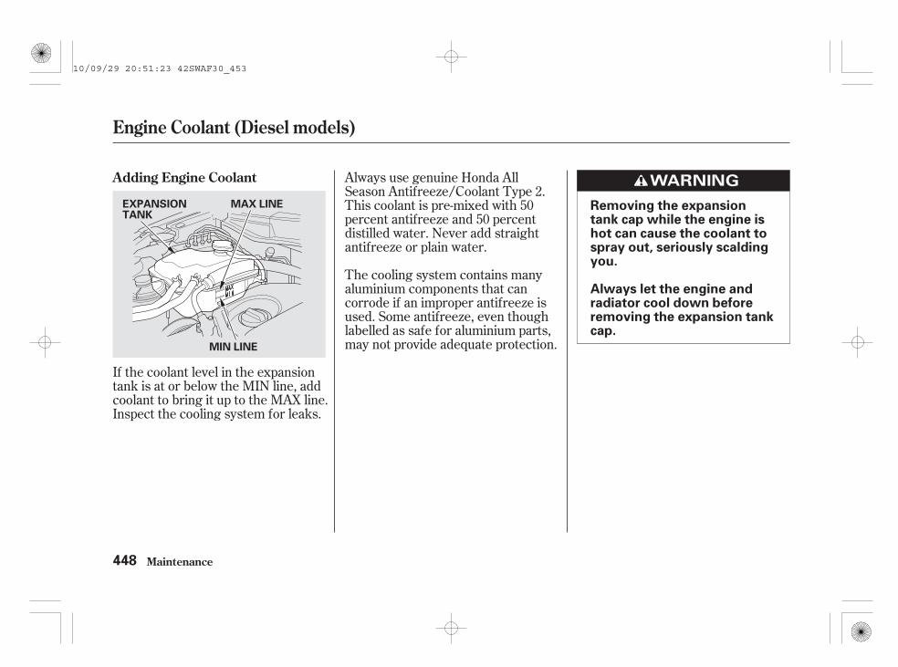
If the coolant level in the expansiontank is at or below the MIN line, addcoolant to bring it up to the MAX line.Inspect the cooling system for leaks.
Always use genuine Honda AllSeason Antifreeze/Coolant Type 2.This coolant is pre-mixed with 50percent antifreeze and 50 percentdistilled water. Never add straightantifreeze or plain water.
The cooling system contains manyaluminium components that cancorrode if an improper antifreeze isused. Some antifreeze, even thoughlabelled as safe for aluminium parts,may not provide adequate protection.
Adding Engine Coolant
Maintenance
Engine Coolant (Diesel models)
448
Removing the expansiontank cap while the engine ishot can cause the coolant tospray out, seriously scaldingyou.
Always let the engine andradiator cool down beforeremoving the expansion tankcap.
EXPANSIONTANK
MIN LINE
MAX LINE
10/09/29 20:51:23 42SWAF30_453

The coolant level should be up tothe MAX line. Add coolant if it islow.
Pour the coolant slowly andcarefully so you do not spill any.Clean up any spills immediately; itcould damage components in theengine compartment.
Put the expansion tank cap backon, and tighten it fully.
Do not add any rust inhibitors orother additives to your vehicle’scooling system. They may not becompatible with the coolant orengine components.
Remove the expansion tank cap bypushing down and turninganticlockwise.
Make sure the engine and radiatorare cool.
Loosen the expansion tank cap byturning it 1/8 turn anticlockwise.This will relieve any remainingpressure in the cooling system.
2.
3.
4.
5.
1.
Engine Coolant (Diesel models)
Maintenance 449
CAP MAX LINE
10/09/29 20:51:34 42SWAF30_454

Check the fluid level in thewindscreen washer reservoir at leastmonthly during normal use.
Check the fluid level by removingthe cap and looking at the levelgauge.
Fill the reservoir with a good-qualitywindscreen washer fluid. Thisincreases the cleaning capability andprevents freezing in cold weather.
When you refill the reservoir, cleanthe edges of the windscreen wiperblades with windscreen washer fluidon a clean cloth. This will help tocondition them.
Do not use engine antifreeze or avinegar/water solution in thewindscreen washer reservoir.Antifreeze can damage your vehicle’spaint, while a vinegar/water solutioncan damage the windscreen washerpump. Use only commercially-available windscreen washer fluid.
Windscreen Washers
Maintenance450
Petrol models Diesel models LEVEL GAUGELEVEL GAUGE
2.0 engine model is shown.
10/09/29 20:51:42 42SWAF30_455

Remove the dipstick (yellow loop)from the transmission, and wipe itwith a clean cloth.
Check the fluid level with the engineat normal operating temperature.
Park the vehicle on level ground.Start the engine, let it run until theradiator fan comes on, then shutoff the engine. For accurateresults, wait about 60 seconds (butno longer than 90 seconds) beforedoing step 2.
1.
2.
CONTINUED
Automatic Transmission Fluid
Maintenance 451
2.0 engine model DIPSTICK
DIPSTICKDIPSTICK GUIDEDIPSTICK GUIDE
2.4 engine modelDIPSTICK Diesel model
10/09/29 20:51:51 42SWAF30_456

Insert the dipstick all the way backinto the transmission securely asshown in the illustration.
Remove the dipstick and checkthe fluid level. It should bebetween the upper and lowermarks.
If the level is below the lowermark, add fluid into the dipstickhole to bring it to the levelbetween the upper and lowermarks.
Pour the fluid slowly and carefully soyou do not spill any. Clean up anyspill immediately; it could damagecomponents in the enginecompartment.
3. 5.
4.
Automatic Transmission Fluid
Maintenance452
UPPERMARK
LOWERMARK
2.0 engine model
UPPERMARKLOWERMARK
2.4 engine model Diesel model
LOWER MARKUPPER MARK
10/09/29 20:52:00 42SWAF30_457
Always use Honda GenuineATF-Z1 (automatic transmissionfluid).
The transmission should be drainedand refilled with new fluid accordingto the time and distancerecommendations in themaintenance schedule.
Always use genuine Honda ManualTransmission Fluid (MTF). If it isnot available, you may use an APIservice SJ or higher grade motor oilwith a viscosity of SAE 10W-30 or10W-40 as a temporary replacement.However, motor oil does not containthe proper additives, and continueduse can cause stiffer shifting.Replace as soon as it is convenient.
Insert the dipstick all the way backinto the transmission securely asshown in the illustration.
If you are not sure how to add fluid,contact your dealer.
Make sure the rubber cap on thedipstick fits in the dipstick guideand that you push the dipstick inall the way.
The transmission should be drainedand refilled with new fluid accordingto the time and distancerecommendations in themaintenance schedule.
Use only Honda Genuine ATF-Z1(automatic transmission fluid). Donot mix with other transmissionfluids.Using transmission fluid other thanHonda Genuine ATF-Z1 may causedeterioration in transmissionoperation and durability, and couldresult in damage to the transmission.Damage resulting from the use oftransmission fluid other than HondaGenuine ATF-Z1 is not covered bythe Honda new vehicle warranty.
6.
2.0 and 2.4 engine models
Manual Transmission Fluid
Automatic Transmission Fluid, Manual Transmission Fluid
Maintenance 453
10/09/29 20:52:12 42SWAF30_458

*
-
*
The rear differential should bedrained and refilled with new fluidaccording to the recommendation ofthe maintenance schedule. Haveyour dealer replace the reardifferential fluid.
Use genuine Honda DPSF-II only. Donot use automatic transmission fluid(ATF).
Check the fluid level in thereservoirs monthly.
Brake fluid reservoir (all models)Clutch fluid reservoir(manual transmission only)
You will also see the symbol ‘‘ ,’’or this symbol with a ‘‘BRAKEFLUID LOW’’ message on the multi-information display when the brakefluid level is low.
Replace the brake fluid according tothe recommendation in themaintenance schedule.
Always use genuine Honda BrakeFluid or an equivalent from a sealedcontainer that is marked DOT3 orDOT4 only. Brake fluid markedDOT5 is not compatible with yourvehicle’s braking system.
The transfer assembly fluid shouldbe drained and refilled with new fluidaccording to the time and distancerecommendations in themaintenance schedule . Have yourdealer replace the transfer assemblyfluid.
For EU countries and SouthAfrica, see the separate serviceinformation booklet.
Use a SAE 90 viscosity hypoid gearoil, API service classified GL4 orGL5 only, in the transfer assembly.
Viscosity
:
On diesel model with automatictransmission
Rear Differential Fluid Brake and Clutch FluidTransfer Assembly Fluid
Maintenance
Rear Differential Fluid, Transfer Assembly Fluid, Brake and Clutch Fluid
454
SAE 90: above 18°C
10/09/29 20:52:26 42SWAF30_459

A low fluid level can indicate a leakin the clutch system. Have thissystem inspected as soon as possible.
The fluid level should be betweenthe MIN and MAX marks on the sideof the reservoir. If it is not, addbrake fluid to bring it up to that level.Use the same fluid specified for thebrake system.
The fluid level should be betweenthe MIN and MAX marks on the sideof the reservoir. If the level is at orbelow the MIN mark, your brakesystem needs attention. Have thebrake system inspected for leaks orworn brake pads.
Brake and Clutch Fluid
Maintenance
Clutch SystemBrake System
455
Petrol models
MIN
MAX
MIN
Diesel models
MAX
MINMAX
Diesel model is shown.
10/09/29 20:52:36 42SWAF30_460

A low power steering fluid level canindicate a leak in the system. Checkthe fluid level frequently, and havethe system inspected as soon aspossible.
Turning the steering wheel to fullleft or right lock and holding it therecan damage the power steeringpump.
Pour the fluid slowly and carefully soyou do not spill any. Clean up anyspills immediately; it could damagecomponents in the enginecompartment.
Using automatic transmission fluidor another brand of power steeringfluid will damage the system. Useonly genuine Honda Power SteeringFluid (V, II or S).
You should check the fluid level inthe power steering reservoir at leastonce a year. Check the level on theside of the reservoir when theengine is cold. The fluid should bebetween the UPPER LEVEL andLOWER LEVEL. If not, add powersteering fluid to the UPPER LEVELmark.
Maintenance
Power Steering Fluid (For some types)
456
LOWER LEVEL
UPPER LEVEL
10/09/29 20:52:44 42SWAF30_461

The air cleaner element should bereplaced according to the time anddistance recommendations in themaintenance schedule.
The air cleaner element is inside theair cleaner housing in the enginecompartment.To replace it:
The air cleaner element should alsobe cleaned according to themaintenance schedule.
Clean the air cleaner element byblowing compressed air through it inthe opposite direction to normal airflow. If you do not have access tocompressed air (such as a servicestation), ask your dealer to do thisservice.
Follow the replacement procedurefor removal and reinstallation.
Unsnap the three hold-down clipsand remove the air cleanerhousing cover.Make sure to free the two detentsof the air cleaner housing coverfrom their holders.
1.
CONTINUED
On vehicles with dry type air cleanerelement
2.0 engine model
Air Cleaner Element (Petrol models)
Maintenance
ReplacementCleaning
457
CLIPS
DETENT HOLDER
10/09/29 20:52:57 42SWAF30_462

Remove the old air cleanerelement.
Carefully clean the inside of theair cleaner housing with a damprag.
Place the new air cleaner elementin the air cleaner housing.
To replace it:
The air cleaner element is inside theair cleaner housing in the enginecompartment.
Unsnap the five hold-down clipsand remove the air cleanerhousing cover.
Make sure all detents are securedin their holders.
Reinstall the air cleaner housingcover, and snap the three hold-down clips back into place. Makesure they are securely latched.
2.
3.
4.
5.
1.
2.4 engine model
Air Cleaner Element (Petrol models)
Maintenance458
AIR CLEANER ELEMENT
CLIP
10/09/29 20:53:07 42SWAF30_463

Remove the old air cleanerelement.
Carefully clean the inside of theair cleaner housing with a damprag.
Place the new air cleaner elementin the air cleaner housing.
Reinstall the air cleaner housingcover, and snap the five hold-downclips back into place.
Make sure they are securelylatched.
2.
3.
4.
5.
Air Cleaner Element (Petrol models)
Maintenance 459
AIR CLEANER ELEMENT
10/09/29 20:53:15 42SWAF30_464

To replace it:
The air cleaner element is inside theair cleaner housing in the enginecompartment.
The air cleaner element should bereplaced according to the time anddistance recommendations in themaintenance schedule.
Follow the replacement procedurefor removal and reinstallation.
Unsnap the holding-clips and pullup the front of the air cleanerhousing cover.
Remove the old air cleanerelement.
Carefully clean the inside of theair cleaner housing with a damprag.
Make sure to free the two detentsof the air cleaner housing coverfrom their holders.
1.
2.
3.
Replacement
Air Cleaner Element (Diesel models)
Maintenance460
AIR CLEANER ELEMENT
CLIPS
CLIP
CLIP
DETENT
HOLDER
10/09/29 20:53:27 42SWAF30_465

Place the new air cleaner elementin the air cleaner housing.
Reinstall the air cleaner housingcover, align the detents in theirholders, and snap the holding-clipsback into place.
Make sure they are securelylatched.
4.
5.
Air Cleaner Element (Diesel models)
Maintenance 461
10/09/29 20:53:32 42SWAF30_466

The fuel filter should be replacedaccording to the time and distancerecommendations in the mainte-nance schedule.
Have a qualified technician changethe fuel filter. Since the fuel systemis under pressure, fuel can spray outand create a hazard if all fuel lineconnections are not handledcorrectly.
If this symbol or this symbol with a‘‘WATER IN FUEL FILTER’’message shows on the multi-information display, water hasaccumulated in the fuel system,which may cause damage to the fuelinjection system. Contact your dealeras soon as possible to have the waterdrained off.
After the vehicle has been stored foran extended period, the engine maynot start. If water has accumulated inthe fuel system, you will see thesymbol on the multi-informationdisplay when you turn the ignitionswitch to the ON (II) position. Thismay also be caused by air in the fuelsystem. In this case, follow theprocedure for
(see page ).
It is recommended to replace thefuel filter every 40,000 km (25,000miles), or 2 years (except EU, SouthAfrica and Russia)/every 45,000 km,or 3 years (Russia, Ukraine), if thefuel you are using is suspected to becontaminated. In a high dustenvironment, the filter may becomeclogged sooner.
501
On petrol models
On all models
Draining Water(Diesel models only)
Priming the FuelSystem
Fuel Filter
Maintenance462
10/09/29 20:53:43 42SWAF30_467

**
*
*
Check the operation of your vehicle’sexterior lights at least once a month.A burned out bulb can make thecondition of your vehicle unsafereducing your vehicle’s visibility andthe ability to signal your intentions toother drivers.
If equippedBulb replacement should be done by your dealer.
1 :2 :
CONTINUED
Lights
Maintenance 463
POSITIONLIGHT FRONT TURN
SIGNAL
LOW BEAMHEADLIGHT
HIGH BEAM HEADLIGHT
FRONT FOGLIGHT
SIDE TURNSIGNAL
1
2
10/09/29 20:53:51 42SWAF30_468

*
*
Check the following:
If you find any bulbs are burned out,replace them as soon as possible.Refer to the chart on page todetermine what type of replacementbulb is needed.
Headlights (low and high beam)Position lights
Brake lightsTurn signals
Back-up lightsHazard light functionLicence plate lightsHigh-mount brake light
Rear fog light
Side turn signals
Tail-lights
Front fog lights (for some models)
Rear fog light is installed on the driver’s side only.:
575
Lights
Maintenance464
HIGH-MOUNT BRAKE LIGHT
Left-hand drive type is shown.
TAIL-LIGHT
STOP/TAIL-LIGHT
BACK-UP LIGHT
TURN SIGNALLIGHT
REAR FOG LIGHT LICENCE PLATE LIGHTS
10/09/29 20:54:06 42SWAF30_469

The headlights were properly aimedwhen your vehicle was new. If youregularly carry heavy items in theluggage area or pull a trailer,readjustment may be required.Adjustments should be done by yourdealer or another qualifiedtechnician.
The low beam headlight bulbs arehigh voltage discharge tube bulbs.High voltage can remain in thecircuit even with the light switch offand the key removed. Because ofthis, you should not attempt toexamine or change a low beamheadlight bulb yourself. If a lowbeam headlight bulb fails, take thevehicle to your dealer to have itreplaced.
Your vehicle is equipped with anautomatic headlight adjustingsystem that adjusts the vertical angleof the headlights (low beam)automatically. Refer to page formore information.
The vertical angle of the headlightscan be adjusted. For moreinformation, see page .
Your vehicle has halogen headlightbulbs. When replacing a bulb, handleit by its base, and protect the glassfrom contact with your skin or hardobjects. If you touch the glass, cleanit with denatured alcohol and a cleancloth.
Halogen headlight bulbs get very hotwhen lit. Oil, perspiration, or ascratch on the glass can cause thebulb to overheat and shatter.
158
158
CONTINUED
On vehicles with high voltage dischargetype low beam headlights
On vehicles with halogen headlightbulbs
High Voltage Discharge TubeHeadlights(For some types)
Headlight Aiming Replacing a Headlight Bulb
Lights
Maintenance 465
10/09/29 20:54:19 42SWAF30_470

Open the bonnet.Remove the cover on the back ofthe headlight assembly by turningit anticlockwise.
Remove the electrical connectorfrom the bulb by pulling theconnector straight back.
Unclip the end of the hold-downwire from its slot. Pivot it out ofthe way, and remove the bulb.
To change a bulb on the left side,remove the upper part of the airintake duct.
To change a bulb on the left side,remove the fuse box from its stayby pulling it out.
3.
4.
2.1.
On petrol models On diesel models
Low Beam Headlights
Lights
Maintenance466
COVER
AIR INTAKE DUCT
10/09/29 20:54:31 42SWAF30_471

Open the bonnet.
To change a bulb on the left side,remove the engine coolant reservetank by pulling it out of its holder.
To change a bulb on the right side,remove the power steering fluidtank from the stay.
Reinstall the cover over the backof the headlight assembly and turnit clockwise to lock it in place.
Insert the new bulb into the hole,making sure the tabs are in theirslots. Pivot the hold-down wireback in place, and clip the end intothe slot.
Push the electrical connector ontothe new bulb. Make sure it isconnected securely.
Turn on the headlights to test thenew bulb.
Reinstall the air intake ductsecurely.
Reinstall the fuse box in placesecurely.
1.
7.
8.
9.
5.
6.
CONTINUED
On petrol models On diesel models
On the left side of diesel models
On the left side of petrol models
High Beam Headlights
Lights
Maintenance 467
2.4 engine model is shown.
10/09/29 20:54:45 42SWAF30_472

Install the new bulb, and turn itone-quarter turn clockwise to lockit in place.
Push the electrical connector backonto the bulb. Make sure it is onall the way.
Reinstall the cover over the backof the headlight assembly and turnit clockwise to lock in place.
Turn on the headlights to test thenew bulb.
Remove the cover on the back ofthe headlight assembly by turningit anticlockwise.
Remove the electrical connectorfrom the bulb by pushing on thetab to unlock it, then slide theconnector off the bulb.
Remove the bulb by turning itapproximately one-quarter turnanticlockwise.
Reinstall the coolant reserve tank.
Reinstall the power steeringreservoir tank.
5.
6.
7.
8.
3.
4.
2. 9. On the left side of petrol models
On the right side of diesel models
Lights
Maintenance468
COVER
10/09/29 20:54:57 42SWAF30_473

Insert the socket back into theheadlight assembly. Turn itclockwise to lock it in place.
Turn on the lights to make surethe new bulb is working.
Open the bonnet.
Pull the bulb straight out of itssocket. Push the new bulb straightinto the socket until it bottoms.
To change a bulb on the left side,remove the upper part of the airintake duct.
Remove the socket from theheadlight assembly by turning itone-quarter turn anticlockwise.
Reinstall the air intake ductsecurely.
4.
5.
6.
1. 2.
3.
On diesel models
On the left side of diesel models
Replacing a Front Turn SignalLight Bulb
Lights
Maintenance 469
AIR INTAKE DUCT
10/09/29 20:55:07 42SWAF30_474

A front position light bulb is locatedunderneath the high beam headlightbulb under the cover.
Open the bonnet.
Remove the cover on the back ofthe headlight assembly by turningit anticlockwise.
Pull the bulb straight out of itssocket. Push the new bulb straightinto the socket until it bottoms.
Remove the socket from theheadlight assembly by turning itone-quarter turn anticlockwise.
To remove a bulb on the left side,remove the engine coolant reservetank (see page ).
To change a bulb on the right side,remove the power steeringreservoir tank (see page ).
2.
1.
3.
4.
467
467
On petrol models
On diesel models
Replacing a Front Position LightBulb
Lights
Maintenance470
COVER
10/09/29 20:55:19 42SWAF30_475

Insert the new bulb into theheadlight assembly. Make sure itis on all the way.
Reinstall the cover over the backof the headlight assembly and turnit clockwise to lock in place.
Turn on the lights to make surethe new bulb is working.
Open the tailgate. Place a cloth onthe edge of the cover to preventscratches. Remove the covers bycarefully prying on the edge with asmall flat-tip screwdriver. Pull the tail-light assembly out of
the rear pillar.
Use a Phillips-head screwdriver toremove the tail-light assemblymounting screw under each cover.
Reinstall the coolant reserve tank.
Reinstall the power steeringreservoir tank.
5.
6.
7.
1. 2.
3.
8.
CONTINUED
On the left side of petrol models
On the right side of diesel models
Replacing Rear Bulbs
Lights
Maintenance 471
SCREWS
COVER
10/09/29 20:55:31 42SWAF30_476

Determine which bulb is burnedout: stop/tail-light, back-up light,turn signal, tail-light, or rear foglight on the driver’s side only.
Remove the socket for that bulbby turning it one-quarter turnanticlockwise.
Remove the bulb from the socketby pushing it in and turning thebulb anticlockwise until it unlocks.
Pull the bulb straight out of itssocket. Push the new bulb straightinto the socket until it bottoms.
Reinstall the socket into the lightassembly by turning it clockwiseuntil it locks.
Turn on the lights to make surethe new bulb is working.
Align the clips on the tail-lightassembly with the holes in thebody, then push the tail-lightassembly into place. Tighten thetwo mounting screws securely andreinstall the covers.
Open the tailgate.Unlatch the top of the cover bypulling back on it with your hands.
4.
5.
6.
7.
8.
9.
1.
Except for tail-light bulb
Tail-light bulb
Lights
Maintenance
Replacing a High-mount BrakeLight Bulb
472
BULBS
COVER
10/09/29 20:55:43 42SWAF30_477
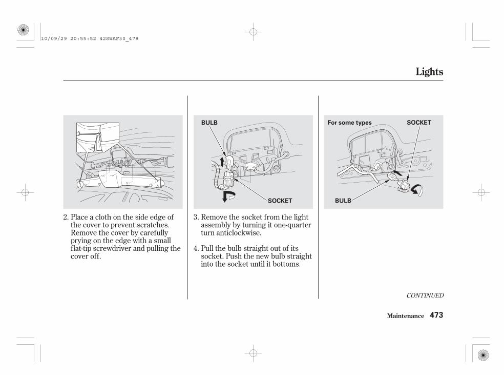
CONTINUED
Place a cloth on the side edge ofthe cover to prevent scratches.Remove the cover by carefullyprying on the edge with a smallflat-tip screwdriver and pulling thecover off.
Remove the socket from the lightassembly by turning it one-quarterturn anticlockwise.
Pull the bulb straight out of itssocket. Push the new bulb straightinto the socket until it bottoms.
2. 3.
4.
Lights
Maintenance 473
BULB
For some typesBULB
SOCKET
SOCKET
10/09/29 20:55:52 42SWAF30_478
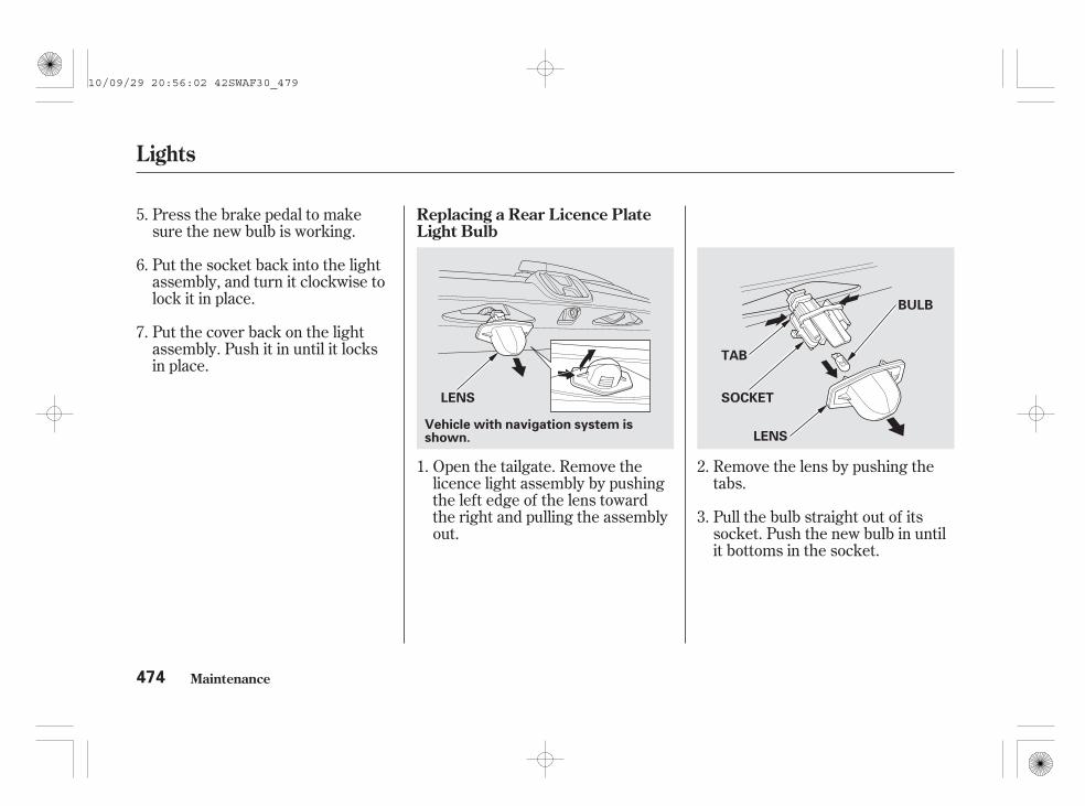
Remove the lens by pushing thetabs.
Pull the bulb straight out of itssocket. Push the new bulb in untilit bottoms in the socket.
Open the tailgate. Remove thelicence light assembly by pushingthe left edge of the lens towardthe right and pulling the assemblyout.
Press the brake pedal to makesure the new bulb is working.
Put the socket back into the lightassembly, and turn it clockwise tolock it in place.
Put the cover back on the lightassembly. Push it in until it locksin place.
6.
7.
5.
3.
1. 2.
Replacing a Rear Licence PlateLight Bulb
Lights
Maintenance474
Vehicle with navigation system isshown.
LENS
TAB
LENS
SOCKET
BULB
10/09/29 20:56:02 42SWAF30_479

Turn on the position lights andcheck that the new bulb isworking.
Put the lens back on the socketuntil it locks.
Slide the right side of the lightassembly into the hole. Push onthe left side to latch the assemblyinto place.
Your vehicle uses halogen lightbulbs. When replacing a bulb, handleit by its plastic case, and protect theglass from contact with your skin orhard objects. If you touch the glass,clean it with denatured alcohol and aclean cloth.
Halogen light bulbs get very hotwhen lit. Oil, perspiration, or ascratch on the glass can cause thebulb to overheat and shatter.
The front fog lights were properlyaimed when your vehicle was new. Ifyou regularly carry heavy items inthe luggage area or pull a trailer,readjustment may be required.Adjustment should be done by yourdealer or other qualified technician.
Remove the mounting bolt with awrench and remove the twofasteners with a flat-tipscrewdriver.
Pull down the under cover fromthe bumper carefully.
4.
5.
6.
1.
CONTINUED
On petrol modelsOn diesel models (Right Side)
Replacing a Front Fog Light Bulb(For some types)
Lights
Maintenance 475
BOLT
UNDER COVER
FASTENERS
10/09/29 20:56:15 42SWAF30_480

Remove the electrical connectorfrom the bulb by squeezing theconnector to unlock the tab, thenslide the connector off the bulb.
Remove the bulb by turning itapproximately one-quarter turnanticlockwise.
Remove the screw with a Phillips-head screwdriver, then removethe lower fin carefully from the airduct cover by pushing the finoutward.
2.On diesel models (Left side)
Lights
Maintenance476
SCREW
FIN
CONNECTOR
BULB BULB
CONNECTORPetrol modelsDiesel models(Left side)
10/09/29 20:56:23 42SWAF30_481

Insert the new bulb into the holeand turn it one-quarter turnclockwise to lock it in place.
Push the electrical connector backonto the bulb. Make sure it is onall the way.
Turn on the front fog lights to testthe new bulb.
The ceiling light, spotlights, luggagearea light, and vanity mirror lightscome apart the same way, but theydo not use the same type of bulbs.
When removing a lens, put a clothon the edge of the lens to preventscratches. Pry carefully on theedge of it with a fingernail file, orsmall flat-tip screwdriver. Do notpry on the edge of the housingaround the lens. Ceiling light:
Pry on the front edge of the lensnear both sides.
Reinstall the under cover and putthe two fasteners back in place,then tighten the mounting boltsecurely.
Reinstall the fin and tighten thescrew securely.
1.
4.
5.
6.
3.
CONTINUED
On petrol models
On diesel models (Left side)
On diesel models (Right Side)
Replacing Bulbs in the InteriorLights
Lights
Maintenance 477
CEILING LIGHT
10/09/29 20:56:35 42SWAF30_482

Push the new bulb into the holder.Snap the lens back in place.
Remove the bulb by pulling itstraight out of its holder.
Vanity mirror light:Pry on the bottom edge of the lens.
Luggage area light:Pry on the side edge of the lens inthe middle.
Spotlights:Pry on the inner edge of bothspotlights.
3.
2.
Lights
Maintenance478
SPOTLIGHTS VANITY MIRROR LIGHTLUGGAGE AREA LIGHT
Vehicle with sunroof is shown.
10/09/29 20:56:44 42SWAF30_483

Your vehicle’s air conditioning is asealed system. Any majormaintenance, such as recharging,should be done by a qualifiedtechnician. You can do a couple ofthings to make sure the airconditioning works efficiently.
Periodically check the engine’sradiator and air conditioningcondenser for leaves, insects, anddirt stuck to the front surface. Theseblock the air flow and reduce coolingefficiency. Use a light spray from ahose or a soft brush to remove them.
The condenser and radiator finsbend easily. Only use a low-pressurespray or soft-bristle brush to cleanthem.
Run the air conditioning at least oncea week during the cold weathermonths. Run it for at least 10minutes while you are driving at asteady speed with the engine atnormal operating temperature. Thiscirculates the lubricating oil con-tained in the refrigerant.
If the air conditioning does not get ascold as before, have your dealercheck the system. Recharge thesystem with Refrigerant HFC-134a(R-134a).
Whenever you have the airconditioning system serviced, makesure the service facility uses arefrigerant recycling system. Thissystem captures the refrigerant forreuse. Releasing refrigerant into theatmosphere can damage theenvironment.
Air Conditioning System
Maintenance 479
AIR CONDITIONING CONDENSER
10/09/29 20:56:53 42SWAF30_484
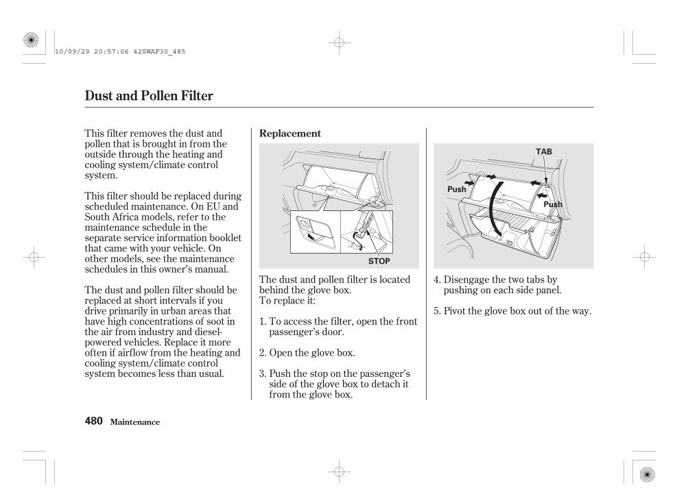
This filter removes the dust andpollen that is brought in from theoutside through the heating andcooling system/climate controlsystem.
The dust and pollen filter is locatedbehind the glove box.To replace it:
To access the filter, open the frontpassenger’s door.
Open the glove box.
Disengage the two tabs bypushing on each side panel.
Pivot the glove box out of the way.
Push the stop on the passenger’sside of the glove box to detach itfrom the glove box.
This filter should be replaced duringscheduled maintenance. On EU andSouth Africa models, refer to themaintenance schedule in theseparate service information bookletthat came with your vehicle. Onother models, see the maintenanceschedules in this owner’s manual.
The dust and pollen filter should bereplaced at short intervals if youdrive primarily in urban areas thathave high concentrations of soot inthe air from industry and diesel-powered vehicles. Replace it moreoften if airflow from the heating andcooling system/climate controlsystem becomes less than usual.
1.
2.
3.
4.
5.
Replacement
Dust and Pollen Filter
Maintenance480
TAB
Push
Push
STOP
10/09/29 20:57:06 42SWAF30_485

Pivot the glove box up intoposition. Install the tabs back inplace.
Install the case. Make sure bothtabs ‘‘click’’ into place.
Install the new filter in the case.Make sure the arrows of the ‘‘AIRFLOW’’ marks on the filter pointto the airflow direction(downward).
Remove the filter from the case.Remove the dust and pollen filtercase by pushing in on the lock tabs,then pulling the case toward you.
Install the glove box stop.
Close the glove box.
If you are not sure how to replacethe dust and pollen filter, have itreplaced by your dealer.
7.
8.
6.
9.
10.
11.
Dust and Pollen Filter
Maintenance 481
DUST AND POLLEN FILTERTAB
10/09/29 20:57:17 42SWAF30_486

Check the condition of the wiperblades at least every six months.Replace them if you find signs ofcracking in the rubber, areas that aregetting hard, or if they leave streaksand unwiped areas when used.
Disconnect the blade assemblyfrom the wiper arm:
To replace a front wiper blade:
Raise each wiper arm off thewindscreen, lifting the driver’sside first, then the passenger’sside.
Do not open the bonnet when thewiper arms are raised, or you willdamage the bonnet and the wiperarms.
Press and hold the lock tab.
Slide the blade assembly towardthe lock tab until it releases fromthe wiper arm.
When replacing a wiper blade,make sure not to drop the wiperblade or wiper arm down on thewindscreen.
1.
2.
Wiper Blades
Maintenance482
LOCK TAB
WIPER ARMS
FRONT
10/09/29 20:57:29 42SWAF30_487

Examine the new wiper blades. Ifthey have no plastic or metalreinforcement along the backedge, remove the metalreinforcement strips from the oldwiper blade, and install them inthe slots along the edge of the newblade.
Make sure the three rubber tabsinside the blade fit to each notchof the reinforcement, as shown.
Remove the blade from its holderby grasping the tabbed end of theblade. Pull firmly until the tabscome out of the holder.
4.
3.
CONTINUED
Wiper Blades
Maintenance 483
REINFORCEMENT
TOP
BLADE
BLADE
10/09/29 20:57:38 42SWAF30_488
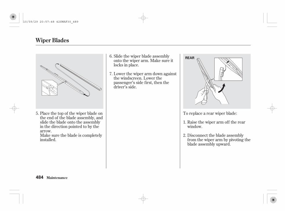
Place the top of the wiper blade onthe end of the blade assembly, andslide the blade onto the assemblyin the direction pointed to by thearrow.Make sure the blade is completelyinstalled.
Slide the wiper blade assemblyonto the wiper arm. Make sure itlocks in place.
Lower the wiper arm down againstthe windscreen. Lower thepassenger’s side first, then thedriver’s side.
Raise the wiper arm off the rearwindow.
Disconnect the blade assemblyfrom the wiper arm by pivoting theblade assembly upward.
To replace a rear wiper blade:5.
6.
7.
1.
2.
Wiper Blades
Maintenance484
REAR
10/09/29 20:57:48 42SWAF30_489

Pull one end of the blade out fromthe holder.Slide the blade out of the holder.
Examine the new wiper blades. Ifthey have no plastic or metalreinforcement along the backedge, remove the metalreinforcement strips from the oldwiper blade, and install them inthe slots along the edge of the newblade.
Slide the new blade into the holder.Make sure it is engaged in the slotalong its full length.Insert both ends of the blade intothe holder. Make sure they aresecure.
Install the wiper blade assemblyonto the wiper arm. Make sure itlocks in place.
Lower the wiper arm against thewindscreen.
3.
5.
4.
6.
7.
Wiper Blades
Maintenance 485
10/09/29 20:57:58 42SWAF30_490

To safely operate your vehicle, yourtyres must be the proper type andsize, in good condition with adequatetread, and correctly inflated.
The following pages give moredetailed information on how to takecare of your tyres and what to dowhen they need to be replaced.
Keeping the tyres properly inflatedprovides the best combination ofhandling, tread life, and ridingcomfort.
Underinflated tyres wear unevenly,adversely affect handling and fueleconomy, and are more likely tofail from being overheated.
Overinflated tyres can make yourvehicle ride more harshly, aremore prone to damage from roadhazards, and wear unevenly.
The deflation warning system willwarn you when a change in tyrerevolutions occurs due to a decreasein tyre pressure. See page formore information on the deflationwarning system.
Even though your vehicle isequipped with deflation warningsystem, we recommend that youvisually check your tyres every day.If you think a tyre might be low,check it immediately with a tyregauge. Then initialise the deflationwarning system (see page ).
404
407
Inflation Guidelines
Tyres
Maintenance486
Using tyres that areexcessively worn orimproperly inflated can causea crash in which you can beseriously hurt or killed.
Follow all instructions in thisowner’s manual regardingtyre inflation andmaintenance.
10/09/29 20:58:08 42SWAF30_491

Use a gauge to measure the airpressure in each tyre at least once amonth. Even tyres that are in goodcondition may lose 10 to 20 kPa (0.1to 0.2 kgf/cm , 1 to 2 psi) per month.Remember to check the spare tyre atthe same time.
Check the air pressure when thetyres are cold. This means thevehicle has been parked for at leastthree hours, or driven less than 1.6km (1 mile). Add or release air, ifneeded, to match the recommendedcold tyre pressures on the label onthe driver’s doorjamb.
If you check air pressures when thetyres are hot [driven for severalkilometers (miles)], you will seereadings 30 to 40 kPa (0.3 to 0.4kgf/cm , 4 to 6 psi) higher than thecold readings. This is normal. Do notlet air out to match therecommended cold air pressure. Thetyre will be underinflated.
CONTINUED
Tyres
Maintenance 487
10/09/29 20:58:14 42SWAF30_492

You should get your own tyrepressure gauge and use it wheneveryou check your tyre pressures. Thiswill make it easier for you to tell if apressure loss is due to a tyreproblem and not due to a variationbetween gauges.
While tubeless tyres have someability to self-seal if they arepunctured, you should look closelyfor punctures if a tyre starts losingpressure.
For convenience, the recommendedcold air pressures and tyre sizes areon a label on the driver’s doorjamb.
Every time you check inflation, youshould also examine the tyres fordamage, foreign objects, and wear.You should look for:
Bumps or bulges in the tread orside of the tyre. Replace the tyre ifyou find either of these conditions.
Cuts, splits, or cracks in the sideof the tyre. Replace the tyre if youcan see fabric or cord.
Excessive tread wear.Your tyres have wear indicatorsmolded into the tread. When thetread wears down, you will see aband 12.7 mm (1/2 inch) wide acrossthe tread. This shows there is lessthan 1.6 mm (1/16 inch) of tread lefton the tyre.
A tyre this worn gives very littletraction on wet roads. You shouldreplace the tyre if you can see threeor more tread wear indicators.
Tyre Inspection
Tyres
Maintenance488
INDICATOR LOCATION MARK
TREAD WEAR INDICATOR
10/09/29 20:58:25 42SWAF30_493

In addition to proper inflation,correct wheel alignment helps todecrease tyre wear. If you find a tyreis worn unevenly, have your dealercheck the wheel alignment.
Have your dealer check the tyres ifyou feel a consistent vibration whiledriving. A tyre should always berebalanced if it is removed from thewheel. When you have new tyresinstalled, make sure they arebalanced. This increases ridingcomfort and tyre life. For bestresults, have the installer perform adynamic balance.
Improper wheel weights can damageyour vehicle’s aluminium wheels.Use only genuine Honda wheelweights for balancing.
To help increase tyre life anddistribute wear more evenly, rotatethe tyres every 10,000 km (6,250miles). Move the tyres to thepositions shown in the illustrationseach time they are rotated. Theabove illustration shows how thetyres should be rotated on thevehicles equipped with a compactspare tyre or when the normal sparetyre is not included in the tyrerotation.
For vehicles equipped with aluminiumwheels:
CONTINUED
Tyre Maintenance Tyre Rotation
Tyres
Maintenance 489
Front
(For directionaltyres and wheels)
(For non-directionaltyres and wheels)
10/09/29 20:58:36 42SWAF30_494

If you purchase directional tyres,rotate only front-to-back.When the tyres are rotated, makesure the air pressures are checked.
Refer to the illustrations in the nextcolumn when the normal spare tyreis also rotated.
After rotating tyres, initialise thedeflation warning system to activateit properly (see page ).407
Tyres
Maintenance490
For non-directional tyres and wheels
(Left-handdrive type)
(Right-handdrive type)
(Left-handdrive type)
(Right-handdrive type)
Front
Front
For directional tyres and wheels
10/09/29 20:58:44 42SWAF30_495
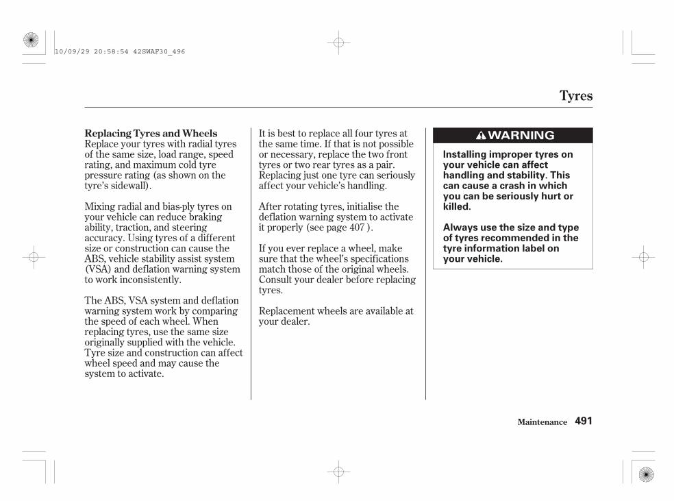
Replace your tyres with radial tyresof the same size, load range, speedrating, and maximum cold tyrepressure rating (as shown on thetyre’s sidewall).
Mixing radial and bias-ply tyres onyour vehicle can reduce brakingability, traction, and steeringaccuracy. Using tyres of a differentsize or construction can cause theABS, vehicle stability assist system(VSA) and deflation warning systemto work inconsistently.
The ABS, VSA system and deflationwarning system work by comparingthe speed of each wheel. Whenreplacing tyres, use the same sizeoriginally supplied with the vehicle.Tyre size and construction can affectwheel speed and may cause thesystem to activate.
It is best to replace all four tyres atthe same time. If that is not possibleor necessary, replace the two fronttyres or two rear tyres as a pair.Replacing just one tyre can seriouslyaffect your vehicle’s handling.
After rotating tyres, initialise thedeflation warning system to activateit properly (see page ).
If you ever replace a wheel, makesure that the wheel’s specificationsmatch those of the original wheels.Consult your dealer before replacingtyres.
Replacement wheels are available atyour dealer.
407
Replacing Tyres and Wheels
Tyres
Maintenance 491
Installing improper tyres onyour vehicle can affecthandling and stability. Thiscan cause a crash in whichyou can be seriously hurt orkilled.
Always use the size and typeof tyres recommended in thetyre information label onyour vehicle.
10/09/29 20:58:54 42SWAF30_496

++
Wheels:
Tyres:
Because of the limited winterqualification of summer tyres forwinter use we recommend the use ofwinter tyres (M S tyres) on snowyand icy roads. If M S tyres areinstalled, all four wheels should beequipped to insure safe driving. Useonly tyres of the same brand withthe same profile. Pay attention to thetyre size, load capacity and speedclass when buying.
The sizes of wheels and tyresinstalled on your vehicle varydepending on models.
See the tyre information label on thedriver’s doorjamb or ask your dealerfor information on the proper size ofthe tyres on your vehicle.
Install the winter tyres according tothe remarks in the registration paper.According to the EEC Directive fortyres, when winter tyres are used, itis necessary to affix a sticker withthe allowable max. speed of thewinter tyres clearly in the field ofview of the driver, if the designedmax. speed of vehicle is higher thanthe allowed max. speed of wintertyre. A sticker is obtainable fromyour tyre dealer. If any questionsarise, please discuss these with oneof our dealers.
On European modelsWinter TyresWheels and Tyres
Tyres
Maintenance492
225/65R17 102T
17 x 6 1/2J18 x 7J
225/60R18 100H
10/09/29 20:59:06 42SWAF30_497

*
*
*
*
Use snow chains only in anemergency or when they are legallyrequired for driving through acertain area. Install the snow chainson the front wheels. Use greatercaution when driving with snowchains on snow or ice. They mayhave less-predictable handling thangood winter tyres without chains.Some snow chains may damage thevehicle’s tyres, wheels, suspension,brake lines and body. Choose onlyfine limbed chains which guaranteeenough free space between the tyreand the other vehicle parts in thewheelhouse. Pay attention to thesectional assembly view and otherdirections from the chainmanufacturer. Consult your dealerbefore purchasing any type of chainsfor your vehicle.
When you have installed tyre chains,drive at less than 30 km/h (19 mph)on roads covered with snow or ice.To minimize tyre and chain wear,avoid driving on cleared roads withchains installed.
Use only the specified chains or theirequivalents for your tyres as listed.
Original tyre is mentioned onthe tyre information label on thedriver’s doorjamb.
On 225/60R18 tyres, you cannotinstall any type of tyre chains. Ifyou have to use tyre chains,replace the original tyres withthe optional 225/65R17 tyre.
2:
1:
Original Tyre Size Chain Type1
2
Except EU modelsTyre Chains
Tyres
Maintenance 493
225/65R17 102T
225/60R18 100H
RUD DISK4715454 orequivalent
NotAvailable
10/09/29 20:59:16 42SWAF30_498

*
*
*
*
Chain Type
Use only the specified chains or their equivalents for your tyres as listed.
On 225/60R18 tyres, you cannot install any type of tyre chains. If youhave to use tyre chains, replace the original tyres with the optional225/65R17 tyre.
Original tyre is mentioned on the tyre information label on the driver’sdoorjamb.
Original Tyre Size
1:
2:
1
2
For EU models
Tyres
Maintenance494
RUD DISK 4715454 or equivalents
Not Available
225/65R17 102T
225/60R18 100H
10/09/29 20:59:25 42SWAF30_499

-
Check the condition of the batterymonthly by looking at the testindicator window. The label on thebattery explains the test indicator’scolours.
Check the terminals for corrosion (awhite or yellowish powder). Toremove it, cover the terminals with asolution of baking soda and water. Itwill bubble up and turn brown. Whenthis stops, wash it off with plainwater. Dry off the battery with acloth or paper towel. Coat theterminals with grease to help preventfuture corrosion.
The location of the test indicatorwindow varies betweenmanufacturers.
If you need to connect the battery toa charger, disconnect both cables toprevent damaging your vehicle’selectrical system. Always disconnectthe negative ( ) cable first, andreconnect it last.
If additional battery maintenance isneeded, see your dealer or aqualified technician.
CONTINUED
Checking the Battery
Maintenance 495
TEST INDICATOR WINDOW
2.0 engine model
TEST INDICATOR WINDOW
2.4 engine model
TEST INDICATOR WINDOW
Diesel models
10/09/29 20:59:36 42SWAF30_500

-
-
-
Flush with water from a cupor other container for at least 15minutes. (Water under pressure candamage the eye.) Call a physicianimmediately.
Remove contaminatedclothing. Flush the skin with largequantities of water. Call a physicianimmediately.
Drink water or milk.Call a physician immediately.
Emergency Procedures
Eyes
Skin
Swallowing
Checking the Battery
Maintenance496
The battery gives offexplosive hydrogen gasduring normal operation. Aspark or open flame cancause the battery to explodewith enough force to kill orseriously hurt you.
Keep all sparks, open flames,and smoking materials awayfrom the battery.
Wear protective clothing anda face shield, or have a skilledtechnician do the batterymaintenance.
The battery contains sulfuricacid (electrolyte) which ishighly corrosive andpoisonous.
Getting electrolyte in youreyes or on your skin cancause serious burns. Wearprotective clothing and eyeprotection when working onor near the battery.
Swallowing electrolyte cancause fatal poisoning ifimmediate action is nottaken.
KEEP OUT OF THE REACH OFCHILDREN
10/09/29 20:59:43 42SWAF30_501

-
-
Loosen the bolt on the negativebattery cable, then disconnect thecable from the negative ( )terminal.
Always disconnect the negative( ) cable first, and reconnect itlast.
If your vehicle’s battery isdisconnected, or goes dead, the timesetting is lost. To reset the time, seepage .
If your vehicle’s battery isdisconnected or goes dead, the audiosystem may disable itself. The nexttime you turn on the radio, you willsee ‘‘ENTER CODE’’ in thefrequency display. Use the presetbuttons to enter the code (see page
).
Open the bonnet.
Make sure the ignition switch is inthe LOCK (0) position.
When you remove and replace thebattery, always follow themaintenance instructions inMaintenance Safety on page andthe warnings in the Checking theBattery section to prevent potentialhazards.1.
2.
3.
291
293
426
On some types
On some types
(For EU countries)
CONTINUED
Replacing the Battery
Maintenance
Checking the Battery, Replacing the Battery
497
NEGATIVETERMINAL
POSITIVE TERMINAL
POSITIVETERMINALCOVER
BOLT
STAY
CABLE
CLIP Diesel model is shown.
BATTERY BRACKET
NUT
10/09/29 20:59:56 42SWAF30_502

+
To install a new battery, reverse thisprocedure.
Open the positive battery terminalcover. Loosen the bolt on thepositive battery cable, thendisconnect the cable from thepositive ( ) terminal.
Make sure the battery bracket ispositioned correctly as shown on theprevious page.
This symbol on the batterymeans that this product mustnot be treated as householdwaste.
An improperly disposed of batterycan be harmful to the environmentand human health.Always confirm local regulations forbattery disposal.
Pull out the cable by pulling theclip from the holder on the side ofthe battery case.
Take out the battery carefully.
If necessary, remove the batterycover.
Pull the bottom end of eachbattery stay out of the hole on thebattery base, and remove thecombination of the battery bracketand the stays.
Loosen the nut on each side of thebattery bracket with a wrench.
4.
5.
6.
7.
8.
On diesel models
Replacing the Battery
Maintenance498
10/09/29 21:00:08 42SWAF30_503

If you need to park your vehicle foran extended period (more than 1month), there are several things youshould do to prepare it for storage.Proper preparation helps preventdeterioration and makes it easier toget your vehicle back on the road. Ifpossible, store your vehicle indoors.
Fill the fuel tank.
Wash and dry the exteriorcompletely.
Clean the interior. Make sure thecarpeting, floor mats, etc., arecompletely dry.
Leave the parking brake off. Putthe transmission in reverse(manual) or Park (automatic).
Block the rear wheels.
If the vehicle is to be stored for alonger period, it should besupported on jackstands so thetyres are off the ground.
Leave one window open slightly (ifthe vehicle is being storedindoors).
Disconnect the battery.
Support the front and rear wiperblade arms with a folded towel orrag so they do not touch thewindscreen.
To minimize sticking, apply asilicone spray lubricant to all doorand tailgate seals. Also, apply avehicle body wax to the paintedsurfaces that mate with the doorand tailgate seals.
CONTINUED
Maintenance
Vehicle Storage
499
10/09/29 21:00:19 42SWAF30_504

*
* For EU countries and SouthAfrica, see the separate serviceinformation booklet.
If you store your vehicle for 1 year orlonger, have your dealer perform themaintenance inspections called for inthe 2 years/40,000 km (25,000 miles)maintenance schedule as soon asyou take it out of storage (see page
). The replacements called for inthe maintenance schedule are notneeded unless the vehicle hasactually reached that time ordistance.
When parking the vehicle for anextended period, wateraccumulates in the fuel systemand the engine will not start. Inthis case, water may need to bedrained off with the fuel filter (see
on page ).
Cover the vehicle with a‘‘breathable’’ cover, one madefrom a porous material such ascotton. Non-porous materials, suchas plastic sheeting, trap moisture,which can damage the paint.
If possible, periodically run theengine until it reaches fulloperating temperature (thecooling fans cycle on and offtwice). Preferably, do this once amonth. :
462429
On diesel models only
Vehicle Storage
Maintenance
Draining Water
500
10/09/29 21:00:27 42SWAF30_505

If your vehicle runs out of fuel, themalfunction indicator lamp will comeon, or the symbol ‘‘ ’’ willappear on the multi-informationdisplay, and the engine will notrestart after refueling the fuel tankwith the appropriate fuel (see pages
and ).
In this case, air may have enteredthe fuel system. The system requirespriming to start the engine. Primethe fuel system as follows:
Refuel the fuel tank (minimum 5litres).
Turn the ignition key to the ON(II) position and hold it for about30 seconds.
The engine runs normally, but themalfunction indicator lamp or thePGM-FI warning remains on.
You may hear some noise near thefuel tank (located under the rearseat) for a while. This is normal: itis the fuel system being primedautomatically.
Make sure the glow plugsindicator goes off, then start theengine (see page ). If theengine does not start right away,do not hold the ignition switch formore than 10 seconds at a time.This will damage the fuel pumpand the engine starter.
If the engine fails to start, returnto step 2.
To turn off the indicator, restartand turn off the engine at leastthree times at intervals ofapproximately 60 seconds.
1.
3.
2.
4.
5.
6.
353 354
375
CONTINUED
Priming the Fuel System(Diesel models only)
Vehicle Storage
Maintenance 501
10/09/29 21:00:40 42SWAF30_506

If this procedure is performedduring normal driving, themalfunction indicator lamp will beturned off, and the PGM-FI warningon the multi-information display willalso go out.
If you are not sure how to bleed theair, contact your dealer.
If the engine fails to restart afterpriming the fuel system, there is aproblem in the fuel system. Youshould have the vehicle inspected byyour dealer.
Vehicle Storage
Maintenance502
10/09/29 21:00:46 42SWAF30_507

Regular cleaning and polishing ofyour vehicle helps to keep it ‘‘new’’looking. This section gives youinformation on how to clean yourvehicle and preserve its appearance:the paint, brightwork, wheels andinterior. Also included are severalthings you can do to help preventcorrosion.
.................................Exterior Care . 504.....................................Washing . 504
.......................................Waxing . 505...................Aluminium Wheels . 505
..........................Audio Antenna . 506
..........................Paint Touch-up . 506..................................Interior Care . 507...................................Carpeting . 507.................................Floor Mats . 507
.........................................Fabric . 508...........................................Vinyl . 508
.......................................Leather . 508....................................Windows . 508...................................Seat Belts . 509
..........................Air Fresheners . 509....................Corrosion Protection . 510
Appearance Care
Appearance Care 503
10/09/29 21:00:51 42SWAF30_508

Frequent washing helps preserveyour vehicle’s beauty. Dirt and gritcan scratch the paint, while tree sapand bird droppings can permanentlyruin the finish.
Wash your vehicle in a shady area,not in direct sunlight. If the vehicle isparked in the sun, move it into theshade and let the exterior cool downbefore you start.
Only use the solvents and cleanersrecommended in this owner’smanual.
Chemical solvents and strongcleaners can damage the paint, metal,and plastic on your vehicle.
Rinse the vehicle thoroughly withcool water to remove loose dirt.
Fill a bucket with cool water. Mixin a product made especially forcar washing.
Wash the vehicle using water anddetergent solution and a soft-bristle brush, sponge, or soft cloth.Start at the top and work your waydown. Rinse frequently.
Check the body for road tar, treesap, etc. Remove these stains withtar remover or turpentine. Rinse itoff immediately so it does notharm the finish. Remember to re-wax these areas, even if the rest ofthe vehicle does not need waxing.
When you have washed and rinsedthe whole exterior, dry it with achamois or soft towel. Letting itair-dry will cause dulling and waterspots.
As you dry the vehicle, inspect it forchips and scratches that could allowcorrosion to start. Repair them withtouch-up paint (see page ).506
Exterior Care
Washing
Appearance Care504
10/09/29 21:01:01 42SWAF30_509

-
-Always wash and dry the wholevehicle before waxing it. You shouldwax your vehicle, including the metaltrim, whenever water sits on thesurface in large patches. It shouldform into beads or droplets afterwaxing.
You should use a quality liquid orpaste wax. Apply it according to theinstructions on the container. Ingeneral, there are two types ofproducts:
Waxes A wax coats the finish andprotects it from damage by exposureto sunlight, air pollution, etc. Youshould use a wax on your vehiclewhen it is new.
Polishes Polishes and cleaner/waxes can restore the shine to paintthat has oxidized and lost some of itsshine. They normally contain mildabrasives and solvents that removethe top layer of the finish. Youshould use a polish on your vehicle ifthe finish does not have its originalshine after using a wax.
Cleaning tar, insects, etc. withremovers also takes off the wax.Remember to re-wax those areas,even if the rest of the vehicle doesnot need waxing.
Clean your vehicle’s aluminium alloywheels as you do the rest of theexterior. Wash them with the samesolution, and rinse them thoroughly.
The wheels have a protectiveclearcoat that keeps the aluminiumfrom corroding and tarnishing. Usingharsh chemicals, including somecommercial wheel cleaners or stiffbrushes, can damage this clear-coat.Only use a mild detergent and softbrush or sponge to clean the wheels.
Exterior Care
Appearance Care
Waxing Aluminium Wheels(For some types)
505
10/09/29 21:01:13 42SWAF30_510

Your dealer has touch-up paint tomatch your vehicle’s colour. Thecolour code is printed on a plate onthe front doorjamb on the left side.Take this code to your dealer so youare sure to get the correct colour.
Inspect your vehicle frequently forchips or scratches in the paint.Repair them right away to preventcorrosion of the metal underneath.Use the touch-up paint only on smallchips and scratches. More extensivepaint damage should be repaired bya professional.
Your vehicle is equipped with anantenna at the rear of the roof.Before using a ‘‘drive-through’’ carwash, remove the antenna byunscrewing it by hand. This preventsthe antenna from being damaged bythe car wash brushes.
Exterior Care
Appearance Care
Paint Touch-upAudio Antenna
506
10/09/29 21:01:21 42SWAF30_511

Vacuum the carpeting frequently toremove dirt. Ground-in dirt will makethe carpet wear out faster.Periodically shampoo the carpet tokeep it looking new. Use one of thefoam-type carpet cleaners on themarket. Follow the instructions thatcome with the cleaner, applying itwith a sponge or soft brush. Keepthe carpeting as dry as possible bynot adding water to the foam.
The driver’s floor mat that camewith your vehicle hooks over thefloor mat anchors. This keeps thefloor mat from sliding forward andpossibly interfering with the pedals.
If you remove the driver’s floor mat,make sure to re-anchor it when youput it back in your vehicle.
If you use non-Honda floor mats,make sure they fit properly and thatthey can be used with the floor matanchors. Do not put additional floormats on top of an anchored mat.
Interior Care
Appearance Care
Carpeting Floor Mats(Optional)
507
10/09/29 21:01:29 42SWAF30_512

Vacuum dirt and dust out of thematerial frequently. For generalcleaning, use a solution of mild soapand lukewarm water, letting it air dry.To clean off stubborn spots, use acommercially-available fabric cleaner.Test it on a hidden area of the fabricfirst, to make sure it does not bleachor stain the fabric. Follow theinstructions that come with thecleaner.
Remove dirt and dust with a vacuumcleaner. Wipe the vinyl with a softcloth dampened in a solution of mildsoap and water. Use the samesolution with a soft-bristle brush onmore difficult spots. You can also usecommercially-available spray orfoam-type vinyl cleaners.
Vacuum dirt and dust from theleather frequently. Pay closeattention to the pleats and seams.Clean the leather with a soft clothdampened with a 90% water and 10%neutral wool detergent solution.Then buff it with a clean, dry cloth.Remove any dust or dirt on leathersurfaces immediately.
Clean the windows, inside and out,with a commercially-available glasscleaner. You can also use a mixtureof one part white vinegar to ten partswater. This will remove the haze thatbuilds up on the inside of thewindows. Use a soft cloth or papertowels to clean all glass and clearplastic surfaces.
The rear window demister wires arebonded to the inside of the glass.Wiping vigorously up-and-down candislodge and break the demisterwires. When cleaning the rearwindow, use gentle pressure andwipe side-to-side.
Interior Care
Appearance Care
Vinyl
Leather(For some types)
WindowsFabric
508
10/09/29 21:01:40 42SWAF30_513
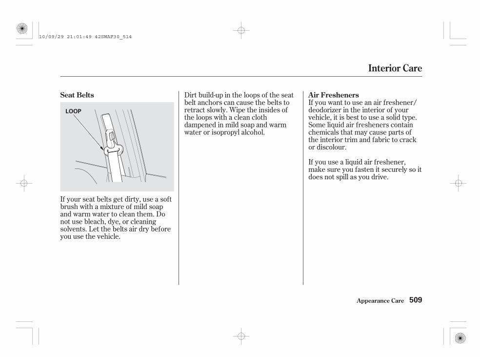
If your seat belts get dirty, use a softbrush with a mixture of mild soapand warm water to clean them. Donot use bleach, dye, or cleaningsolvents. Let the belts air dry beforeyou use the vehicle.
If you want to use an air freshener/deodorizer in the interior of yourvehicle, it is best to use a solid type.Some liquid air fresheners containchemicals that may cause parts ofthe interior trim and fabric to crackor discolour.
If you use a liquid air freshener,make sure you fasten it securely so itdoes not spill as you drive.
Dirt build-up in the loops of the seatbelt anchors can cause the belts toretract slowly. Wipe the insides ofthe loops with a clean clothdampened in mild soap and warmwater or isopropyl alcohol.
Seat Belts Air Fresheners
Interior Care
Appearance Care 509
LOOP
10/09/29 21:01:49 42SWAF30_514

Two factors normally contribute tocausing corrosion in your vehicle:
Moisture trapped in body cavities.Dirt and road salt that collects inhollows on the underside of thecar stays damp, promotingcorrosion in that area.
Removal of paint and protectivecoatings from the exterior andunderside of the vehicle.
Many corrosion-preventive measuresare built into your vehicle. You canhelp keep your vehicle fromcorroding by performing somesimple periodic maintenance:
Repair chips and scratches in thepaint as soon as you discover them.
Inspect and clean out the drainholes in the bottom of the doorsand body.
Check the floor coverings fordampness. Carpeting and floormats may remain damp for a longtime, especially in winter. Thisdampness can eventually causethe floor panels to corrode.
Use a high-pressure spray to cleanthe underside of your vehicle. Thisis especially important in areasthat use road salt in winter. It isalso a good idea in humid climatesand areas subject to salty air. Becareful of the ABS wheel sensorsand wiring at each wheel.
Have the corrosion-preventivecoatings on the underside of yourvehicle inspected and repairedperiodically.
1.
2.
Corrosion Protection
Appearance Care510
10/09/29 21:02:00 42SWAF30_515

This section covers the morecommon problems that motoristsexperience with their vehicles. Itgives you information about how tosafely evaluate the problem and whatto do to correct it. If the problem hasstranded you on the side of the road,you may be able to get going again.If not, you will also find instructionson getting your vehicle towed.
.....................Compact Spare Tyre . 512...................Changing a Flat Tyre . 513
...................................Honda TRK . 519.............If the Engine Won’t Start . 534
................................Jump Starting . 536If the Engine Overheats
.........................(Petrol models) . 540If the Engine Overheats
.........................(Diesel models) . 542.........Low Oil Pressure Indicator . 544
.......................Oil Level Indicator . 545..........Charging System Indicator . 547
Malfunction Indicator Lamp.........................(Petrol models) . 548
Malfunction Indicator Lamp.........................(Diesel models) . 549
PGM-FI Warning.........................(Diesel models) . 550
...............Brake System Indicator . 551..............................................Fuses . 552
Fuse Locations.........................(Petrol models) . 557
Fuse Locations.........................(Diesel models) . 559
......................Emergency Towing . 562
Taking Care of the Unexpected
Taking Care of the Unexpected
511
10/09/29 21:02:05 42SWAF30_516

Use the compact spare tyre as atemporary replacement only. Getyour regular tyre repaired orreplaced, and put it back on yourvehicle as soon as you can.
Check the air pressure of thecompact spare tyre every time youcheck the other tyres. It should beinflated to:
Replace the tyre when you can seethe tread wear indicator bars. Thereplacement tyre should be the samesize and design, mounted on thesame wheel. The spare tyre is notdesigned to be mounted on a regularwheel, and the spare wheel is notdesigned for mounting a regular tyre.
Follow these precautions:
Never exceed 80 km/h (50 mph).
This tyre gives a harsher ride andless traction on some roadsurfaces. Use greater cautionwhile driving.
Do not mount snow chains on thecompact spare tyre.
Do not use your compact sparetyre on another vehicle unless it isthe same make and model.
Do not use more than onecompact spare tyre at the sametime.
When you restart the vehicle withthe compact spare tyre, do notinitialise the system, because thecompact spare tyre is smaller thanthe regular tyre. After replacingthe compact spare tyre with thespecified regular tyre, initialise thedeflation warning system.
The compact spare tyre is smallerthan the regular tyre. Yourvehicle’s ground clearancereduces when the compact sparetyre is installed. Driving over roaddebris or bumps could possiblydamage the underside of yourvehicle.
Compact Spare Tyre (For some types)
Taking Care of the Unexpected512
TREAD WEAR INDICATOR BAR
INDICATOR LOCATION MARK
420 kPa (4.2 kgf/cm , 60 psi)
10/09/29 21:02:17 42SWAF30_517

CONTINUED
If you have a flat tyre while driving,pull over safely. Drive slowly alongthe shoulder until you get to an areafar away from traffic lanes.
Your vehicle is equipped with thetyre sealant kit instead of the sparetyre. This kit is available for easyrepair of a flat tyre (see page ).
Use the jack that came with yourvehicle. If you try to raise anothervehicle with this jack or use anotherjack to raise your vehicle, the vehicleor jack can be damaged.
Park the vehicle on firm, level, andnon-slippery ground. Put thetransmission in Park (automatic)or reverse (manual). Apply theparking brake.
If you are towing a trailer, unhitchthe trailer.
Jack Label
See Owner’s Manual.
Never get under vehicle whensupported by jack.
Place jack underneath reinforcedarea.
See page for your jack type.
1.
1. 2. 3.
1.
2.
3.
519575
On vehicles with spare tyre
On vehicles with Honda TRK
Changing a Flat Tyre
Taking Care of the Unexpected 513
The vehicle can easily roll offthe jack, seriously injuringanyone underneath.
Follow the directions forchanging a tyre exactly, andno person should place anyportion of their body under avehicle that is supported by ajack.
10/09/29 21:02:31 42SWAF30_518

Turn on the hazard warning lights,and turn the ignition switch to theLOCK (0) position. Have all thepassengers get out of the vehiclewhile you change the tyre.
Open the tailgate. Raise theluggage area floor lid by lifting upwith the strap, and remove it fromluggage area by disengaging thetabs.
When you store the flat tyre in thespare tyre well, do not reinstall theluggage area floor lid forcibly.This will damage the tabs on thelid.
Take the tool kit out of the sparetyre well.
Open the tailgate. Raise theluggage area floor lid by lifting itup with the strap.
(For some types)
4.
3.2.
Changing a Flat Tyre
Taking Care of the Unexpected514
TAB
TOOLS
JACK
FLOOR LIDSPARE TYRE
SPARE TYRE
TOOL
JACK
FLOOR LID
10/09/29 21:02:43 42SWAF30_519

CONTINUED
Place the jack under the jackingpoint nearest the tyre you need tochange. Turn the end bracketclockwise until the top of the jackcontacts the jacking point. Makesure the jacking point tab isresting in the jack notch.
Loosen each wheel nut 1/2 turnwith the wheel nut wrench.
Take the jack out of the spare tyrearea.
Unscrew the wing bolt and takethe spare tyre out of its well.
Turn the jack’s end bracketanticlockwise to loosen it, thenremove the jack by lifting itstraight up.
Place blocks in front and back ofthe wheel diagonally opposite thetyre you are changing.
9.8.5.
6.
7.
Changing a Flat Tyre
Taking Care of the Unexpected 515
WHEEL NUT WRENCH
JACKING POINT
JACK
10/09/29 21:02:55 42SWAF30_520
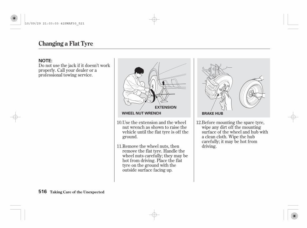
Before mounting the spare tyre,wipe any dirt off the mountingsurface of the wheel and hub witha clean cloth. Wipe the hubcarefully; it may be hot fromdriving.Remove the wheel nuts, then
remove the flat tyre. Handle thewheel nuts carefully; they may behot from driving. Place the flattyre on the ground with theoutside surface facing up.
Use the extension and the wheelnut wrench as shown to raise thevehicle until the flat tyre is off theground.
Do not use the jack if it doesn’t workproperly. Call your dealer or aprofessional towing service.
12.
11.
10.
Changing a Flat Tyre
Taking Care of the Unexpected516
NOTE:
BRAKE HUBWHEEL NUT WRENCH
EXTENSION
10/09/29 21:03:03 42SWAF30_521

CONTINUED
Remove the centre cap beforestoring the flat tyre in the sparetyre well.
Store the centre cap in the sparetyre well. Make sure it does notget scratched or damaged.
Tighten the wheel nuts securely inthe same crisscross pattern. Havethe wheel nut torque checked atthe nearest automotive servicefacility.
Tighten the wheel nuts to:
Put on the spare tyre. Put thewheel nuts back on finger-tight,then tighten them in a crisscrosspattern with the wheel nut wrenchuntil the wheel is firmly againstthe hub. Do not try to tighten thewheel nuts fully.
Lower the vehicle to the ground,and remove the jack.
13.
14.
15. 16.
Changing a Flat Tyre
Taking Care of the Unexpected 517
CENTRE CAP
108 N·m (11 kgf·m , 80 lbf·ft)
10/09/29 21:03:13 42SWAF30_522

Secure the flat tyre by screwingthe wing bolt back into its hole.
Store the jack in its holder. Turnthe jack’s end bracket to lock it inplace. Store the tools, and placethe cover on the flat tyre of theluggage area.
Close the tailgate.
To remove the spacer cone, squeezethe tabs on the wing bolt todisengage it from the centre of thespacer cone, then pull the boltdownward.
To install the wing bolt to the spacercone, reverse this procedure.
Place the flat tyre face down in thespare tyre well.
Remove the spacer cone from thewing bolt, turn it over, and put itback on the bolt.
After replacing the compact sparetyre with the specified regular tyre,initialise the deflation warningsystem (see page ).
19.
20.
21.
17.
18.
22.
407
Changing a Flat Tyre
Taking Care of the Unexpected518
Loose items can fly aroundthe interior in a crash andcould seriously injure theoccupants.
Store the wheel, jack, andtools securely before driving.
For normaltyre
For sparetyre
TAB
SPACER CONE
10/09/29 21:03:24 42SWAF30_523

*
*
Your vehicle is not equipped with aspare tyre. Instead, your vehicle hasthe tyre sealant kit (Honda TRK:temporary repair kit of TERRA-S ).This kit is available only for easyrepair of a flat tyre.
You should check the usable periodof the tyre sealant according to thetime and distance recommendationsin the maintenance schedule .
When using the tyre sealant kit,always follow the instructions andthe procedure in this owner’s manual.
To remind you of the instructions forusing the tyre sealant kit, thehandling manual is included in thekit. Symbols on thehandling manual are to remind youto read this owner’s manual for usingthe tyre sealant kit.
Read the handling manual well anduse it correctly.
Small punctures in the tyre tread,caused by a nail or a screw, can besealed with the temporary repair kit.
The tyre sealant kit cannot be usedin the following cases.Inform your dealer or a RoadsideAssistance Service.
Expired best before date of thetyre sealant.
Cuts or piercing in the tyre treadlarger than approximately 4 mm(3/16ths of an inch).
2 or more tyres punctured.
A rim damaged.
A tyre bead completely unseatedoutside or inside of rim.
Tyre damage caused by drivingwith considerably reduced tyrepressure or even with deflatedtyres.
Cuts in the tyre side wall.
Have your vehicle towed (seeEmergency Towing on page ).
If your vehicle has a compact sparetyre, see page for how to replacea flat tyre.
Refer to the maintenanceschedule in the Service Bookthat came with your vehicle.
1.
2.
3.
4.
5.
6.
7.
:
512 562
CONTINUED
On vehicles with Service Book
On vehicles with Honda TRK
Honda TRK (For some types)
Taking Care of the Unexpected 519
10/09/29 21:03:40 42SWAF30_524

Pull out a nail or a screw in thetyre tread with the pliers suppliedin the tool kit. When you can’t pullit out or you can’t find it, werecommend you to inform yourdealer or Roadside AssistanceService. The kit can also be usedto repair the tyre withoutremoving the nail or screw butonly in unavoidable cases.
Open the tailgate.
If you have a flat tyre while driving,stop in a safe place. Make sure topark the vehicle on firm, level andnon-slippery ground. Put thetransmission in park (automatic) orneutral (manual), and set theparking brake.
If you are towing a trailer, unhitchthe trailer.
Turn on the hazard warning lights,and turn the ignition switch to theLOCK (0) position.
Have all the passengers get out ofthe vehicle while you repair a flattyre temporarily.
Take the Honda TRK (aircompressor, sealant bottle, fillerhose, package including a valveremover and seals, and instruction)out of the case.
1.
Honda TRK (For some types)
Taking Care of the Unexpected
Instructions for Use
520
NAIL/SCREW
PLIER
TOOL KIT
HONDA TRK
10/09/29 21:03:50 42SWAF30_525

CONTINUED
Shake the bottle (A). Screw thefiller hose (B) onto the bottle (A),thereby piercing the seal ofaluminium.
2.
Honda TRK (For some types)
Taking Care of the Unexpected 521
If you drive a vehicle afterrepair without extracting anail or a screw, it may causeair leakage again or damagethe inside and burst a tyre. Ifyou have to drive, drivecarefully, especially aroundcorners.
CAP
(A)
(B)
(A)
AluminiumSealed
10/09/29 21:03:58 42SWAF30_526

Unscrew the valve cap (D) fromthe tyre valve (C). Deflate the tyrecompletely pushing the valveinsert using the back of the valveremover (E).
If you have any questions about thetyre sealant kit, please contact yourdealer.
To remind you of the information forrepairing a flat tyre with this sealantkit, the labels are attached on thesealant bottle. Read the instructionscarefully. Symbols on thelabel are to remind you to read theHonda TRK section for using thetyre sealant kit.
If sealant adheres to clothes, it maynot be possible to remove. Be carefulnot to spill any.
3.
Honda TRK (For some types)
Taking Care of the Unexpected
Safety Label on the Sealant Bottle
522
Contains ethylene glycol.
Harmful if swallowed.Swallow plenty of waterand seek medical adviceimmediately.
Irritating to eyes. Rinseimmediately with plenty ofwater and seek medicaladvice.
Keep locked up and out ofthe reach of children.
If you shake the bottle afterconnecting the hose withthe bottle, it may spillsealant. Shake bottle wellbefore connecting hose.
(D)
(E)
(C)
10/09/29 21:04:08 42SWAF30_527

Pull the plug from the filler hoseand screw the filler hose onto thetyre valve (C).
Unscrew the valve insert (F) usingthe valve remover (E). Do not placethe valve insert (F) in sand or dirt.
4.
CONTINUED
Honda TRK (For some types)
Taking Care of the Unexpected 523
A valve insert can jump out, ifair remains in tyre. Be carefulin removing valve insert.
(F)
PLUG
FILLER HOSE
(C)
(C)
(E)
10/09/29 21:04:17 42SWAF30_528

Pull off the filler hose and firmlyscrew the valve insert (F) into thetyre valve (C) using the valveremover (E).
Affix the ‘‘Tyre Sealant in the tyre’’sticker (G) on the wheel.
Hold the filling bottle with the fillerhose downwards and compress.Squeeze the complete contents intothe tyre.
Reinstall the valve cap.
5.
Honda TRK (For some types)
Taking Care of the Unexpected524
(F)
(C)
(G)
(C)
(E)
VALVE CAP
10/09/29 21:04:26 42SWAF30_529
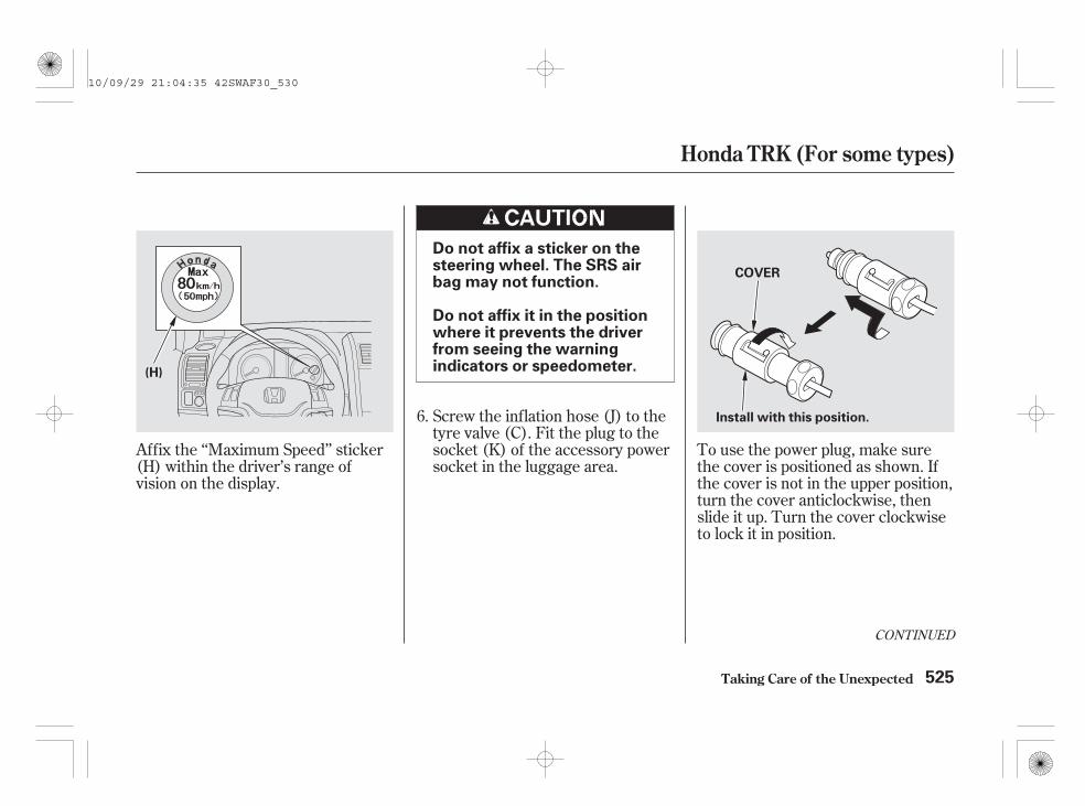
CONTINUED
Screw the inflation hose (J) to thetyre valve (C). Fit the plug to thesocket (K) of the accessory powersocket in the luggage area.
Affix the ‘‘Maximum Speed’’ sticker(H) within the driver’s range ofvision on the display.
To use the power plug, make surethe cover is positioned as shown. Ifthe cover is not in the upper position,turn the cover anticlockwise, thenslide it up. Turn the cover clockwiseto lock it in position.
6.
Honda TRK (For some types)
Taking Care of the Unexpected 525
Do not affix a sticker on thesteering wheel. The SRS airbag may not function.
Do not affix it in the positionwhere it prevents the driverfrom seeing the warningindicators or speedometer.(H)
COVER
Install with this position.
10/09/29 21:04:35 42SWAF30_530

Turn the ignition switch to theACCESSORY (I) position. Turn onthe air compressor (L).Inflate the tyre to the required airpressure (M). Do not inflate the tyrefor more than 10 minutes.If overinflated, deflate air byloosening the screw of the hose.
Operate the electric inflation pumpfor not longer than 15 minutes. It cancause overheating.
Honda TRK (For some types)
Taking Care of the Unexpected526
If the required air pressure isnot reached within 10minutes, the tyre may beseverely damaged.
The Tyre Sealant Kit cannotprovide the necessary seal.Inform a Honda Dealer orRoadside Assistant Service.
POWERPLUG
(M)
(K)(J)
(L) (C)AIR COMPRESSOR SWITCH
AIR PRESSURE GAUGE
ON
OFF
10/09/29 21:04:41 42SWAF30_531

Continue the journey immediately.Drive carefully within the speed of80 km/h (50 mph). If you drive at a speed of more than
80 km/h (50 mph), your vehicle mayvibrate and will not drive safely.
After 10 minutes or 5 km (3 miles)running, check the tyre pressurewith the air compressor pressuregauge. Note that the air pressuremust be checked with the aircompressor turned off. If the tyrepressure is kept, the tyre punctureis sealed. Then initialise thedeflation warning system (seepage ). Continue to drivecarefully to the nearest Hondadealer or a Roadside AssistanceService.
If the required air pressuredropped, inflate the tyre to therequired air pressure and repeatfrom step 6.
7.
8.
9.
407
CONTINUED
Honda TRK (For some types)
Taking Care of the Unexpected 527
10/09/29 21:04:50 42SWAF30_532

If the puncture hole cannot bedetected, the tyre repair shop cannotrepair the sealed tyre. When youcontinue running, check tyrepressure often and if tyre pressuredecreases, have the sealed tyrerepaired at a Honda dealer.
A wheel can be reused afterwiping sealant with cloth, but thevalve must be replaced.
Dispose of the used bottle at aHonda dealer.
Have the tyre replaced at thenearest Honda dealer. To repairthe sealed tyre, consult yourdealer.
Honda TRK (For some types)
Taking Care of the Unexpected528
In the following cases, do notdrive on.Inform a Honda dealer or aRoadside Assistance Service.
The tyre pressure hasdropped below 130 kPa (1.3bar, 19 psi).
The tyre pressure has stilldropped after steps 6 and 7.
10/09/29 21:04:57 42SWAF30_533

To remind you of the information forrepairing a flat tyre with this sealantkit, the labels are attached on the aircompressor. The following showsyou the instructions for these labels.
Symbols on the label areto remind you to read the HondaTRK section for using the tyresealant kit.
CONTINUED
Honda TRK (For some types)
Taking Care of the Unexpected
Instructions for Labels on the AirCompressor
529
Do not run the engine inenclosed areas, or when thevehicle is supported by thejack.
Do not touch the aircompressor with handswithout protective clothing.Because it may be extremelyhot while operating.
Never use the air compressorfor 15 minutes or longer.When reusing, make sure thecompressor is cool to thetouch.
Do not use the aircompressor for any otherpurpose than inflating yourtyres.
10/09/29 21:05:06 42SWAF30_534

The power supply of the aircompressor is limited to yourvehicle’s 12 volt DC accessory socket.
Before using the air compressor,drive your vehicle to the roadshoulder and stop in a safe place thatis far away from the traffic lanes.
Remove the valve cap from a flattyre and securely connect the aircompressor hose to the valve.
Turn the ignition switch to theACCESSORY (I) position. Turn onthe air compressor switch andinflate the tyre to the specified airpressure. Check the tyre pressureby using the air pressure gauge onthe compressor.
Turn off the switch on the aircompressor before checking the airpressure.
Connect the power plug of the aircompressor to the socket of theaccessory power socket.
When the tyre is inflated tospecified air pressure, disconnectthe power plug from the accessorypower socket. Make sure not toleak the air from the tyre. Theninstall and tighten the valve capsecurely.
Step 1.
Step 2.
Step 3.
Step 4.
Honda TRK (For some types)
Taking Care of the Unexpected
Directions
530
NOTE:
10/09/29 21:05:16 42SWAF30_535

Be careful not to spill sealant from atyre.
Remove the tyre and wheel fromthe vehicle.Deflate tyre pressure.
Cut the valve off with a knife.
Be careful not to damage the tyre orthe wheel.
1.
2.
CONTINUED
Honda TRK (For some types)
Taking Care of the Unexpected
Sealant Extraction(For a Honda dealer)
531
Be careful not to cut a handor a finger.
10/09/29 21:05:26 42SWAF30_536

Insert the hose through the valvehole into the tyre.The hose should enter the sealantas deeply as possible.
Squeeze the bottle and draw outthe sealant.(It is better to stand a tyre on atable.)
Repeat step 4 until the sealantcannot be drawn out.
Bend the hose and tie it with thestrap or tape so that sealant doesnot leak. Dispose of the bottle atyour dealer when you replace itwith a new bottle.
Recycling sealant is important forprotecting environmental resources.Please cooperate in collecting usedsealant.
3.
4.
5.
6.
Honda TRK (For some types)
Taking Care of the Unexpected532
10/09/29 21:05:35 42SWAF30_537

To remind you of the information forextracting the used sealant, this sealis attached on the wheel. It alsoshows you the tyre has beenrepaired by the tyre sealant kit. Thefollowing shows you the instructionson this seal.
Symbols on the seal areto remind you to read this owner’smanual for extracting the usedsealant.
Honda TRK (For some types)
Taking Care of the Unexpected
Sealant Label
533
The sealant containsethylene glycol.
Swallowing the sealant cancause fatal poisoning. Drinkwith large quantities of water.Call a physician immediately.
Getting the sealant in youreyes or on your skin cancause serious injury. Flushwith large quantities of waterthoroughly. Call a physicianimmediately.
Keep out of the reach ofchildren.
Make sure to keep thesealant enclosed in the bottle.
SEAL
10/09/29 21:05:43 42SWAF30_538

Diagnosing why the engine won’tstart falls into two areas, dependingon what you hear when you turn theignition switch to the START (III)position:
When you turn the ignition switch tothe START (III) position, you do nothear the normal noise of the enginetrying to start. You may hear aclicking sound, a series of clicks, ornothing at all.
You hear nothing, or almostnothing. The engine’s startermotor does not operate at all, oroperates very slowly.
You can hear the starter motoroperating normally, or the startermotor sounds like it is spinningfaster than normal, but the enginedoes not start up and run. Turn the ignition switch to the ON
(II) position. Turn on theheadlights, and check theirbrightness. If the headlights arevery dim or do not come on at all,the battery is discharged. See
on page .
Check these things:
Check the transmission interlock.With an automatic transmission, itmust be in Park or neutral, or thestarter will not operate.
Turn the ignition switch to theSTART (III) position. If theheadlights do not dim, check thecondition of the fuses. If the fusesare OK, there is probablysomething wrong with theelectrical circuit for the ignitionswitch or starter motor. You willneed a qualified technician todetermine the problem. See
on page .
If the headlights dim noticeably orgo out when you try to start theengine, either the battery isdischarged or the connections arecorroded. Check the condition of thebattery and terminal connections(see page ). You can then tryjump starting the vehicle from abooster battery (see page ).
536
562
495
536
If the Engine Won’t Start
Taking Care of the Unexpected
Nothing Happens or the StarterMotor Operates Very Slowly
Jump Starting
Emergency Towing
534
10/09/29 21:05:54 42SWAF30_539

If you find nothing wrong, you willneed a qualified technician to findthe problem. See
on page .
After you have parked the vehiclefor an extended period or whenthe outside temperature becomesvery high, water accumulates inthe fuel system and the engine willnot start. In this case, you shoulddrain the water from the fuel filter(see page ).
Do you have fuel? Check the fuelgauge; the low fuel indicator maynot be working.
There may be an electricalproblem, such as no power to thefuel pump. Check all the fuses(see page ).
The fuel cutoff switch may beactivated. If the switch is activated,it must be reset before starting theengine (see page ).
In this case, the starter motor’sspeed sounds normal, or even fasterthan normal, when you turn theignition switch to the START (III)position, but the engine does not run.
Are you using the proper startingprocedure? Refer to
on page on petrolmodels and page on dieselmodels.
Are you using a properly codedkey? An improperly coded key willcause the immobilizer systemindicator in the instrument panelto blink rapidly (see page ).
If your vehicle runs out of fuel,priming the fuel system isrequired to restart the engine (seepage ).
After you have stored your vehiclefor an extended period, air mayhave entered the fuel system (see
onpage ).
162
374375
554
361
462
562
501
501
On all models
On diesel models only
EmergencyTowing
The Starter Operates Normally
Starting theEngine
Priming the Fuel System
If the Engine Won’t Start
Taking Care of the Unexpected 535
10/09/29 21:06:09 42SWAF30_540

Although this seems like a simpleprocedure, you should take severalprecautions.
Open the bonnet, and check thephysical condition of the battery.In very cold weather, check thecondition of the electrolyte. If itseems slushy or frozen, do not tryjump starting until it thaws.
If a battery sits in extreme cold, theelectrolyte inside can freeze.Attempting to jump start with afrozen battery can cause it to rupture.
To jump start your vehicle:
You cannot start your vehicle with anautomatic transmission by pushingor pulling it.
Turn off all the electricalaccessories: heater, A/C, climatecontrol, audio system, lights, etc.Put the transmission in neutral(M/T) or Park (A/T), and set theparking brake.
1.2.
Jump Starting
Taking Care of the Unexpected536
A battery can explode if youdo not follow the correctprocedure, seriously injuringanyone nearby.
Keep all sparks, open flames,and smoking materials awayfrom the battery.
10/09/29 21:06:17 42SWAF30_541

+
+
CONTINUED
The numbers in the illustrationsshow you the order to connect thejumper cables.
Connect one jumper cable to thepositive ( ) terminal on yourbattery. Connect the other end tothe positive ( ) terminal on thebooster battery.
3.
Jump Starting
Taking Care of the Unexpected 537
2.2 engine model (Diesel)2.0 engine model
BOOSTER BATTERY
2.4 engine model
BOOSTER BATTERY BOOSTER BATTERY
10/09/29 21:06:26 42SWAF30_542

--
Connect the second jumper cableto the negative ( ) terminal onthe booster battery. Connect theother end to the stud bolt on theengine side as shown. Do notconnect this jumper cable to anyother part of the engine.
Connect the second jumper cableto the negative ( ) terminal onthe booster battery. Connect theother end to the top of the studbolt as shown. Do not connect thisjumper cable to any other part ofthe engine.
Make sure the engine is coolbefore connecting the cable.
4. On diesel models
Jump Starting
Taking Care of the Unexpected538
2.0 engine model 2.2 engine model (Diesel)2.4 engine model
10/09/29 21:06:36 42SWAF30_543

Once the vehicle is running,disconnect the negative cable fromyour vehicle, then from thebooster battery. Disconnect thepositive cable from your vehicle,and then from the booster battery.
If the booster battery is in anothervehicle, have an assistant startthat vehicle and run it at a fast idle.
Start the vehicle. If the startermotor still operates slowly, checkthat the jumper cables have goodmetal-to-metal contact. Keep the ends of the jumper
cables away from each other andany metal on the vehicle untileverything is disconnected.Otherwise, you may cause anelectrical short.
5.
6.
7.
Jump Starting
Taking Care of the Unexpected 539
10/09/29 21:06:42 42SWAF30_544

If your vehicle overheats, you shouldtake immediate action. The onlyindication may be the temperaturegauge climbing to or above the redmark. Or you may see steam orspray coming from under the bonnet.
Driving with the temperature gaugereading at the red mark can causeserious damage to your engine.
If you see steam and/or spraycoming from under the bonnet,turn off the engine. Wait until yousee no more signs of steam orspray, then open the bonnet.
If you do not see steam or spray,leave the engine running, andwatch the temperature gauge. Ifthe high heat is due to overloading,the engine should start to cooldown almost immediately. If itdoes, wait until the temperaturegauge reading comes down to themidpoint, then continue driving.
If the temperature gauge readingstays at the red mark, turn off theengine.
Look for any obvious coolant leaks,such as a split radiator hose.Everything is still extremely hot,so use caution. If you find a leak, itmust be repaired before youcontinue driving (see
on page ).
The reading of the vehicle’stemperature gauge should stay inthe midrange. If it climbs to the redmark, you should determine thereason (hot day, driving up a steephill, etc.).
Safely pull to the side of the road.Put the transmission in neutral(manual) or Park (automatic), andset the parking brake. Turn off allaccessories, and turn on thehazard warning lights.
1.
2.
3.
4.
5.
562Emergency
Towing
If the Engine Overheats (Petrol models)
Taking Care of the Unexpected540
Steam and spray from anoverheated engine canseriously scald you.
Do not open the bonnet ifsteam is coming out.
10/09/29 21:06:52 42SWAF30_545

Using gloves or a large heavycloth, turn the radiator capanticlockwise, without pushingdown, to the first stop. After thepressure releases, push down onthe cap, and turn it until it comesoff.
Start the engine, and set thetemperature control dial tomaximum heat (climate control toAUTO at ‘‘ ’’). Add coolantto the radiator up to the base ofthe filler neck. If you do not havethe proper coolant mixtureavailable, you can add plain water.Remember to have the coolingsystem drained and refilled withthe proper mixture as soon as youcan.
If the temperature stays normal,check the coolant level in theradiator reserve tank. If it hasgone down, add coolant to theMAX mark. Put the cap back ontightly.
Put the radiator cap back ontightly. Run the engine, and checkthe temperature gauge. If it goesback to the red mark, the engineneeds repair (see
on page ).
If you don’t find an obvious leak,check the coolant level in theradiator reserve tank. Add coolantif the level is below the MIN mark.
If there was no coolant in thereserve tank, you may need to addcoolant to the radiator. Let theengine cool down until the readingreaches the middle of thetemperature gauge, or lower,before checking the radiator.
6.
7.
8.
9.
11.
10.
562Emergency
Towing
If the Engine Overheats (Petrol models)
Taking Care of the Unexpected 541
Removing the radiator capwhile the engine is hot cancause the coolant to sprayout, seriously scalding you.
Always let the engine andradiator cool down beforeremoving the radiator cap.
10/09/29 21:07:03 42SWAF30_546

Your vehicle can overheat for severalreasons, such as lack of coolant or amechanical problem. The onlyindication may be the temperaturegauge climbing to or above the redmark. Or you may see steam orspray coming from under the bonnet.In either case, you should takeimmediate action.
The reading of your vehicle’stemperature gauge should stay inthe midrange under most conditions.It may go higher if you are driving upa long steep hill on a very hot day. Ifit reaches the red mark, you shoulddetermine the reason.
Driving with the temperature gaugereading at the red mark can causeserious damage to your engine.
If you do not see steam or spray,leave the engine running andwatch the temperature gauge. Ifthe high heat is due to overloading(climbing a long, steep hill on ahot day with the A/C running, forexample), the engine should startto cool down almost immediately.If it does, wait until thetemperature gauge reading comesdown to the midpoint, thencontinue driving.
Wait until you see no more signsof steam or spray, then open thebonnet.
If the temperature gauge readingstays at the red mark, turn off theengine.
Safely pull to the side of the road.Put the transmission in neutral(manual) or Park (automatic), andset the parking brake. Turn off theair conditioning system/climatecontrol system and all otheraccessories. Turn on the hazardwarning lights.
If you see steam and/or spraycoming from under the bonnet,turn off the engine.
1.
2.
3.
4.
5.
If the Engine Overheats (Diesel models)
Taking Care of the Unexpected542
Steam and spray from anoverheated engine canseriously scald you.
Do not open the bonnet ifsteam is coming out.
10/09/29 21:07:14 42SWAF30_547

Look for any obvious coolant leaks,such as a split radiator hose.Everything is still extremely hot,so use caution. If you find a leak, itmust be repaired before youcontinue driving (see
on page ).
Start the engine and set thetemperature control dial tomaximum heat (climate control toAUTO at ‘‘ ’’). Add coolant upto the MAX line on the expansiontank. If you do not have the propercoolant mixture available, you canadd plain water. Remember tohave the cooling system drainedand refilled with the propermixture as soon as you can.
Use a cloth or glove to protectyour hand while removing theexpansion tank cap. Loosen thecap by turning it 1/8 turn anticlock-wise. Stop and wait for any pres-sure in the expansion tank toescape. Then remove the cap byturning it anticlockwise.
Put the expansion tank cap backon tightly. Run the engine, andcheck the temperature gauge. If itgoes back to the red mark, theengine needs repair (see
on page ).
If the temperature stays normal,check the coolant level in theexpansion tank. If it has gonedown, add coolant to the MAXmark. Put the expansion tank capback on tightly.
If you don’t find an obvious leak,check the coolant level in theexpansion tank. Add coolant if thelevel is below the MIN mark.
If the expansion tank needscoolant, you will have to removethe cap. Before doing that, turnthe ignition switch to the ON (II)position and check thetemperature gauge. Remove theexpansion tank cap only if thetemperature gauge reading hascome down to normal or below thered mark and you do not hear anybubbling or gurgling noisescoming from the cooling system.
9.8.
7.
6. 10.
11.
12.
562
562
EmergencyTowing
Emergency Towing
If the Engine Overheats (Diesel models)
Taking Care of the Unexpected 543
Removing the expansiontank cap while the engine ishot can cause the coolant tospray out, seriously scaldingyou.
Always let the engine andradiator cool down beforeremoving the expansion tankcap.
10/09/29 21:07:24 42SWAF30_548

Start the engine, and watch the oilpressure indicator. If it does not goout within 10 seconds, turn off theengine. There is a mechanicalproblem that needs to be repairedbefore you can continue driving(see on page
).
Running the engine with low oilpressure can cause seriousmechanical damage almostimmediately. Turn off the engine assoon as you can safely get thevehicle stopped.
Let the vehicle sit for a minute.Open the bonnet, and check the oillevel (see page ). An enginevery low on oil can lose pressureduring cornering and other drivingmanoeuvres.
If necessary, add oil to bring thelevel back to the full mark on thedipstick (see page on petrolmodels, and page on dieselmodels).
This indicator should comeon when the ignition switch
is in the ON (II) position, and go outafter the engine starts. It shouldnever come on red when the engineis running. If it turns on red andstarts flashing or stays on, the oilpressure has dropped very low orlost pressure. Serious enginedamage is possible and you shouldtake immediate action.
You will also see the symbol ‘‘ ,’’or this symbol with an ‘‘OILPRESSURE LOW’’ message on themulti-information display.
Safely pull off the road, and shutoff the engine. Turn on the hazardwarning lights.
1.
2.
4.
3.
357
442444
562Emergency Towing
Taking Care of the Unexpected
Low Oil Pressure Indicator
544
10/09/29 21:07:34 42SWAF30_549

The oil level symbol/messagedisplay can be reset each time youturn off the engine. When you startyour trip again, the system begins tomonitor the engine oil level. It maytake a while until the system sensesthe engine oil level is low and thesymbol, or the symbol with amessage appear on the multi-information display. You shouldcheck the engine oil level and addengine oil before driving again if theoil level symbol, or the symbol with a‘‘CHECK ENGINE OIL LEVEL’’message comes on.
Your vehicle has an engine oil levelsensor to check the oil level. If thesymbol ‘‘ ’’ for the oil levelindicator comes on in the multi-information display when the engineis running, the engine oil level is low.You will also hear a beep when thissymbol comes on. If you select thewarning symbol with the message(s)in the customizing settings, you willsee this symbol with a ‘‘CHECKENGINE OIL LEVEL’’ message onthe multi-information display.
If this symbol comes on, safely pulloff the road, park the vehicle on levelground, turn off the engine and letthe vehicle sit for approximately 3minutes.
Check the oil level. If the engine oillevel is near or below the lower markon the dipstick, you should add theengine oil (see page on petrolmodels, and page on dieselmodels).
Do not fill above the upper mark onthe dipstick and do not spill theengine oil in the engine compartment.This could damage the engine andother components.
If you do not carry spare engine oil inyour vehicle, drive moderately to thenearest service area and add engineoil. Avoid full-throttle accelerationand driving at high speed.
442444
CONTINUED
Oil Level Indicator (On the Multi-information Display)
Taking Care of the Unexpected 545
OIL LEVEL INDICATOR
10/09/29 21:07:44 42SWAF30_550
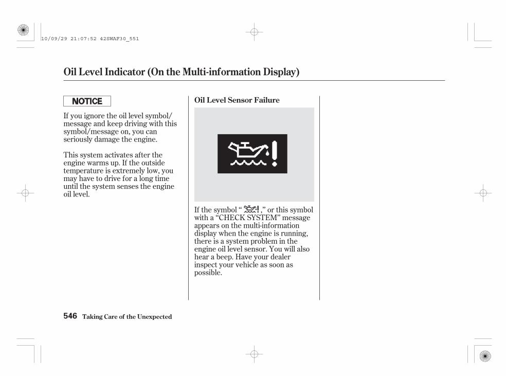
This system activates after theengine warms up. If the outsidetemperature is extremely low, youmay have to drive for a long timeuntil the system senses the engineoil level.
If the symbol ‘‘ ,’’ or this symbolwith a ‘‘CHECK SYSTEM’’ messageappears on the multi-informationdisplay when the engine is running,there is a system problem in theengine oil level sensor. You will alsohear a beep. Have your dealerinspect your vehicle as soon aspossible.
If you ignore the oil level symbol/message and keep driving with thissymbol/message on, you canseriously damage the engine.
Oil Level Sensor Failure
Oil Level Indicator (On the Multi-information Display)
Taking Care of the Unexpected546
10/09/29 21:07:52 42SWAF30_551

Immediately turn off all electricalaccessories. Try not to use otherelectrically operated controls such asthe power windows. Keep the enginerunning; starting the engine willdischarge the battery rapidly.
Go to a dealer or a service stationwhere you can get technicalassistance.
This indicator should comeon when the ignition switch
is in the ON (II) position, and go outafter the engine starts. If thecharging system indicator comes onbrightly when the engine is running,the battery is not being charged.
You will also see the symbol ‘‘ ,’’or this symbol with a ‘‘CHECKSYSTEM’’ message on the multi-information display.
Charging System Indicator
Taking Care of the Unexpected 547
10/09/29 21:07:59 42SWAF30_552

This indicator comes on,then goes out when you
turn the ignition switch to the ON(II) position. If the indicator comeson while driving, it means one of theengine’s emissions control systemsmay have a problem. Even thoughyou may feel no difference in yourvehicle’s performance, it can reduceyour fuel economy and causeincreased emissions. Continuedoperation may cause serious damage.
If you turn the ignition switch to theON (II) position, without starting theengine, the malfunction indicatorlamp will come on for about 20seconds. It then goes off or blinks 5times under various conditions. Thisis normal: it shows the self-testingcondition of the diagnostics for theemissions control systems.
If this indicator comes on, safely pulloff the road and turn off the engine.Restart the engine and watch theindicator. If it stays on, have yourvehicle checked by the dealer assoon as possible. Drive moderatelyuntil the dealer has inspected theproblem. Avoid full-throttleacceleration and driving at highspeed.
You should also have the dealerinspect your vehicle if the indicatorcomes on frequently, even though itgoes off when you follow the aboveprocedure.
If you keep driving with themalfunction indicator lamp on, youcan damage your vehicle’s emissionscontrols and engine. Those repairsmay not be covered by your vehicle’swarranties.
You will also see the symbol ‘‘ ,’’or this symbol with a ‘‘CHECKSYSTEM’’ message on the multi-information display.
If your vehicle has an automatictransmission, the malfunctionindicator lamp may also come onwith the ‘‘D’’ indicator.
Malfunction Indicator Lamp (Petrol models)
Taking Care of the Unexpected548
10/09/29 21:08:08 42SWAF30_553

This indicator comes on,then goes out when you
turn the ignition switch to the ON(II) position. If it comes on at anyother time, it indicates one of theemissions control systems may havea problem. Even though you mayfeel no difference in your vehicle’sperformance, it can reduce your fueleconomy and cause your vehicle toput out excessive emissions.Continued operation may causeserious damage.
This indicator will also come on andyou cannot restart the engine afteryour vehicle has run out of fuel. Ifthis occurs, refuel the fuel tank, thenfollow the procedure for
on page beforeattempting to restart the engine.
If you turn the ignition switch to theON (II) position, without starting theengine, the malfunction indicatorlamp will come on for about 20seconds. It then goes off or blinks 5times under various conditions. Thisis normal: it shows the self-testingcondition of the diagnostics for theemissions control systems.
If this indicator comes on, safely pulloff the road and turn off the engine.Restart and turn off the engine atleast three times at intervals ofapproximately 30 seconds, thenwatch the indicator. If it stays on,have your vehicle checked by your
dealer as soon as possible. Drivemoderately until the dealer hasinspected the problem. Avoid full-throttle acceleration and driving athigh speed.
You should also have the dealerinspect your vehicle if the indicatorcomes on frequently, even though itgoes off when you follow the aboveprocedure.
If you keep driving with themalfunction indicator lamp on, youcan damage your vehicle’s emissionscontrols and engine. Those repairsmay not be covered by your vehicle’swarranties.
You will also see the symbol ‘‘ ,’’or this symbol with a ‘‘CHECKSYSTEM’’ message on the multi-information display.
If your vehicle has an automatictransmission, the malfunctionindicator lamp may also come onwith the ‘‘D’’ indicator.
501Priming
the Fuel System
Malfunction Indicator Lamp (Diesel models)
Taking Care of the Unexpected 549
10/09/29 21:08:17 42SWAF30_554

If this symbol or the symbol with amessage is displayed, safely pull offthe road and turn off the engine.Restart and turn off the engine atleast three times at intervals ofapproximately 30 seconds, thenwatch the multi-information display.If it appears again, have your vehiclechecked by your dealer as soon aspossible. Drive moderately until thedealer has inspected the problem.Avoid full-throttle acceleration anddriving at high speed.
You should also have the dealerinspect your vehicle if this symbol‘‘PGM-FI’’ appears on the multi-information display frequently, eventhough it goes off when you followthe above procedure.
If you keep driving with the symbol‘‘PGM-FI’’ on, you can damage yourvehicle’s emissions controls andengine. Those repairs may not becovered by your vehicle’s warranties.
This symbol or the symbol with amessage will also appear on themulti-information display and youcannot restart the engine after yourvehicle has run out of fuel. If thisoccurs, refuel the fuel tank, thenfollow the procedure for
on page beforeattempting to restart the engine.
This symbol or the symbol with amessage may also appear if you donot use the proper fuel for theclimate or regional conditions. Thismay cause the engine power toreduce (see page ).
If you see this symbol or this symbolwith a ‘‘CHECK SYSTEM’’ messageon the multi-information displaywhile the engine running, there is aproblem with the engine controlsystem. Continued operation maycause serious damage.
501
353
Primingthe Fuel System
PGM-FI Warning (Diesel models)
Taking Care of the Unexpected550
10/09/29 21:08:26 42SWAF30_555

However, if the brake pedal does notfeel normal, you should takeimmediate action. A problem in onepart of the system’s dual circuitdesign will still give you braking attwo wheels. You will feel the brakepedal go down much farther beforethe vehicle begins to slow down, andyou will have to press harder on thepedal.
Slow down by shifting to a lowergear, and pull to the side of the roadwhen it is safe. Because of the longdistance needed to stop, it ishazardous to drive the vehicle. Youshould have it towed and repaired assoon as possible (see
on page ).
The brake system indicatornormally comes on when
you turn the ignition switch to theON (II) position, and as a reminderto check the parking brake. It willstay on if you do not fully release theparking brake.
You will also see the symbol ‘‘ ,’’or this symbol with a ‘‘CHECKSYSTEM’’ message on the multi-information display if there is aproblem with the brake system orthe front-to-rear braking distributionsystem.
If you must drive the vehicle a shortdistance in this condition, driveslowly and carefully.
If the ABS indicator comes on withthe brake system indicator, haveyour vehicle inspected by yourdealer immediately.
You will also see the symbol ‘‘ ,’’or this symbol with a ‘‘BRAKEFLUID LOW’’ message on the multi-information display.
If the fluid level is low, take yourvehicle to a dealer, and have thebrake system inspected for leaks orworn brake pads.
If the brake system indicator comeson while driving, the brake fluid levelis probably low. Press lightly on thebrake pedal to see if it feels normal.If it does, check the brake fluid levelthe next time you stop at a servicestation (see page ).454
562Emergency
Towing
Brake System Indicator
Taking Care of the Unexpected 551
10/09/29 21:08:37 42SWAF30_556

On diesel models
To open the fuse box lid, pull the tabin the direction as shown in theillustration.
The vehicle’s fuses are located inseveral fuse boxes under thedashboard and in the enginecompartment.
The interior fuse box is locatedunder the dashboard on the driver’sside. The fuse label is attachedunder the steering column.
One or two auxiliary fuse boxes arelocated next to the interior fuse box.
Fuses
Taking Care of the Unexpected552
INTERIOR
FUSE LABELFUSE Left-hand drive type model Right-hand drive type model
TAB
AUXILIARYFUSES
LID
TAB LID
AUXILIARY FUSES
10/09/29 21:08:49 42SWAF30_557

The under-bonnet fuse box is locatedin the back of the enginecompartment on the left side. Toopen it, push the tabs as shown.
Fuses
Taking Care of the Unexpected 553
UNDER-BONNET SECONDARY FUSEBOX
TAB
Petrol models
TAB
UNDER-BONNET PRIMARY FUSE BOXDiesel modelsUNDER-BONNET FUSE BOX
10/09/29 21:08:56 42SWAF30_558

Turn the ignition switch to theLOCK (0) position. Make sure theheadlights and all otheraccessories are off.
On the under-bonnet fuse box,remove the cover from the fusebox.
Check each of the large fuses inthe under-bonnet fuse box bylooking through the side windowat the wire inside. Remove thescrews with a Phillips-headscrewdriver.
If something electrical in yourvehicle stops working, the first thingyou should check for is a blown fuse.Determine from the chart on pages
and on petrol models, andpages and on diesel models,or the diagram on the fuse box lid,which fuse or fuses control thatdevice. Check those fuses first, butcheck all the fuses before decidingthat a blown fuse is the cause.Replace any blown fuses, and checkif the device works. 3.
2.
1.
557 558559 561
Checking and Replacing Fuses
Fuses
Taking Care of the Unexpected554
BLOWNBLOWNFUSE FUSE
10/09/29 21:09:05 42SWAF30_559

Look for a burned wire inside thefuse. If it is burned out, replace itwith one of the spare fuses of thesame rating or lower.
If you replace the blown fuse with aspare fuse that has a lower rating, itmight blow out again. This does notindicate that anything is wrong.Replace the fuse with one of thecorrect rating as soon as you can.
Check the smaller fuses in theunder-bonnet fuse box and all thefuses in the interior fuse box bypulling out each one with the fusepuller provided in the under-bonnet fuse box.
On petrol models, the fuse pulleris on the back of the primaryunder-bonnet fuse box cover.
If you cannot drive the vehiclewithout fixing the problem, and youdo not have a spare fuse, take a fuseof the same rating or a lower ratingfrom one of the other circuits. Makesure you can do without that circuittemporarily (such as the cigarettelighter).
5.4.
CONTINUED
Fuses
Taking Care of the Unexpected 555
FUSE PULLER BLOWN
10/09/29 21:09:14 42SWAF30_560

Replacing a fuse with one that has ahigher rating greatly increases thechances of damaging the electricalsystem. If you do not have areplacement fuse with the properrating for the circuit, install one witha lower rating.
If the replacement fuse of thesame rating blows in a short time,there is probably a seriouselectrical problem with yourvehicle. Leave the blown fuse inthat circuit, and have your vehiclechecked by a qualified technician.
Your vehicle has spare fuses on theback of the under-bonnet fuse boxcover.
6.
On petrol models
Fuses
Taking Care of the Unexpected556
FUSE PULLER
SPARE FUSES
10/09/29 21:09:20 42SWAF30_561

*
*
*
*
*
*
*
*
The fuses contained in the under-bonnet fuse box varyslightly depending on models. The locations of fuses areshown with symbols on the fuse label. Refer to the tablebelow for the fuses on your vehicle.
No.
No. Circuits Protected
No. Circuits ProtectedCircuits Protected1
2
3
4
567891011
12
Not usedHeadlight Washer
1213
14
151617181920212223
For some types
Stop, HornDriver’s Power SeatRecliningDriver’s Power SeatSlidingIGPS OIL LEVELLeft-Side e-pretensionerHigh Power SoundIG CoilFI MainMG ClutchDBWInterior LightBack Up
Main Fuse BatteryEPSOption MainIgnition Switch MainVSA Motor/ABS MotorVSA FSR/ABS FSRHeadlight MainPower Window MainRight-Side e-pretensionerSub Fan MotorMain Fan MotorRear DemisterBlowerHazardLAF
:
Fuse Locations (Petrol models)
Taking Care of the Unexpected 557
Secondary
PRIMARY UNDER-BONNET FUSE BOX
SECONDARY UNDER-BONNET FUSE BOX
Primary
10/09/29 21:09:33 42SWAF30_562

*
*
*
* * *
* *
*
--
*
The fuses contained in the interior fuse box vary slightly depending on models.The locations of fuses are shown with symbols on the fuse label. Refer to thetable below for the fuses on your vehicle.
For some types
22232425262728293031
32333435363738AB
123456789101112131415161718192021
Power WindowFuel PumpIG1 ACGABS/VSA UnitHeated SeatsFront Fog LightsDaytime Running LightsRear WiperODS (Occupant Detection System)MeterSRSRight Headlight High BeamLeft Headlight High BeamSmall Lights (Interior)Small Lights (Exterior)Right Headlight Low BeamLeft Headlight Low BeamHeadlight High Beam MainSmall Lights MainRear Fog LightHeadlight Low Beam Main
ACC /EPT /TSA /AFSSTSSunshades /SunroofDoor LockDriver’s Power WindowNot UsedRear Power Accessory SocketFront Accessory Power SocketFront Passenger’s Power WindowAccessory Power Socket (in theConsole Compartment)Rear Right Power WindowRear Left Power WindowAccessory, RadioACC Key LockIG2 HACDaytime LightFront Wiper
:
No.No. Circuits Protected Circuits Protected
Fuse Locations (Petrol models)
Taking Care of the Unexpected558
INTERIOR FUSE BOX
TM
10/09/30 16:40:37 42SWAF30_563
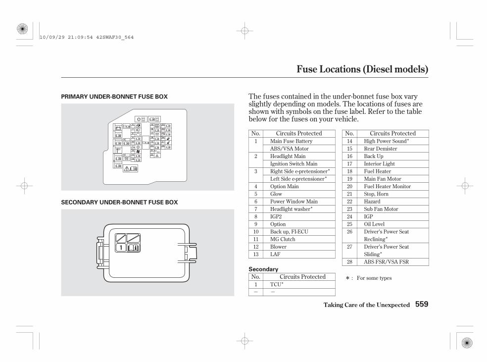
*
*
*
*
*
*
*
- -
*
The fuses contained in the under-bonnet fuse box varyslightly depending on models. The locations of fuses areshown with symbols on the fuse label. Refer to the tablebelow for the fuses on your vehicle.
No.Circuits ProtectedNo.
No. Circuits Protected
Circuits Protected14151617181920212223242526
27
28
For some types
Main Fuse BatteryABS/VSA MotorHeadlight MainIgnition Switch MainRight Side e-pretensionerLeft Side e-pretensionerOption MainGlowPower Window MainHeadlight washerIGP2OptionBack up, FI-ECUMG ClutchBlowerLAF
1
2
3
45678910111213
1 TCU
High Power SoundRear DemisterBack UpInterior LightFuel HeaterMain Fan MotorFuel Heater MonitorStop, HornHazardSub Fan MotorIGPOil LevelDriver’s Power SeatRecliningDriver’s Power SeatSlidingABS FSR/VSA FSR
:
Fuse Locations (Diesel models)
Taking Care of the Unexpected 559
SECONDARY UNDER-BONNET FUSE BOX
Secondary
PRIMARY UNDER-BONNET FUSE BOX
10/09/29 21:09:54 42SWAF30_564

*
*
*
* * *
* *
*
*
The fuses contained in the interior fuse box vary slightlydepending on models. The locations of fuses are shownwith symbols on the fuse label. Refer to the table belowfor the fuses on your vehicle.
For some types
123456789
101112131415161718192021
22232425262728
29
30
31
32333435363738
Power WindowFuel PumpIG1 ACGABS/VSA UnitHeated SeatsFront Fog LightsDaytime Running LightsRear WiperODS (Occupant DetectionSystem)MeterSRSRight Headlight High BeamLeft Headlight High BeamSmall Lights (Interior)Small Lights (Exterior)Right Headlight Low BeamLeft Headlight Low BeamHeadlight High Beam MainSmall Lights MainRear Fog LightHeadlight Low Beam Main
ACC /EPT /TSA /AFSSTSSunshades /SunroofDoor LockDriver’s Power WindowNot UsedRear Power AccessorySocketFront Accessory PowerSocketFront Passenger’s PowerWindowAccessory Power Socket (inthe Console Compartment)Rear Right Power WindowRear Left Power WindowAccessory, RadioACC Key LockIG2 HACDaytime LightFront Wiper
:
No. No.Circuits Protected Circuits Protected
Fuse Locations (Diesel models)
Taking Care of the Unexpected560
INTERIOR FUSE BOX
AUXILIARY FUSES
TM
10/09/30 16:40:44 42SWAF30_565

*
*
* For some types
AB
FI Back upTCU
:
Fuse Locations (Diesel models)
Taking Care of the Unexpected 561
Auxiliary fuse box
A
B
A
B
Right-hand drive type
Left-hand drive type
10/09/29 21:10:10 42SWAF30_566

-
-
-
If your vehicle needs to be towed,call a professional towing service ororganization. Never tow your vehiclewith just a rope or chain. It is verydangerous.
If, due to damage, your vehicle mustbe towed with the front wheels onthe ground, do this:
The towtruck uses metal cables with hookson the ends. These hooks go aroundparts of the frame or suspension andthe cables lift that end of the vehicleoff the ground. Your vehicle’ssuspension and body can beseriously damaged.
The towtruck uses two pivoting arms that gounder the front tyres and lift themoff the ground. The rear tyresremain on the ground.
The operatorloads your vehicle on the back of atruck.
There are three popular types ofprofessional towing equipment.
Start the engine.
Shift the transmission to neutral.Leave the ignition switch in theACCESSORY (I) position so thesteering wheel does not lock.Release the parking brake.
Shift to the D position and hold for5 seconds, then to N.Turn off the engine.
Leave the ignition switch in theACCESSORY (I) position so thesteering wheel does not lock.Release the parking brake.
Improper towing preparation willdamage the transmission. Follow theabove procedure exactly. If youcannot shift the transmission or startthe engine (automatic transmission),your vehicle must be transportedwith the front wheels off the ground.
With the front wheels on the ground,it is best to tow the vehicle no fartherthan 80 km (50 miles), and keep thespeed below 55 km/h (35 mph).
Manual Transmission
Automatic Transmission
On 2WD models
Sling-type Equipment
Wheel-lif t Equipment
Flat-bed Equipment
This method oftowing is unacceptable.
This is anacceptable way to tow yourvehicle.
This is the best way totransport your vehicle.
Emergency Towing
Taking Care of the Unexpected562
10/09/29 21:10:26 42SWAF30_567

The steering system can bedamaged if the steering wheel islocked. Leave the ignition switch inthe ACCESSORY (I) position, andmake sure the steering wheel turnsfreely before you begin towing.
If you decide to tow your vehiclewith all four wheels on the ground,make sure you use a properly-designed and attached tow bar.Prepare the vehicle for towing asdescribed above, and leave theignition switch in the ACCESSORY(I) position so the steering wheeldoes not lock. Make sure the radioand any electrical accessories areturned off so they do not run downthe battery.
Towing with only two tyres on theground will damage parts of the4WD system. It should betransported on a flat-bed truck ortrailer.
Trying to lift or tow your vehicle bythe bumpers will cause seriousdamage. The bumpers are notdesigned to support the vehicle’sweight.
Do not tie down the vehicle at anangle with which the towing cableshit against the vehicle’s frontbumper. To avoid your vehicle fromdamaging, protect the front bumperwith a tape.
The operator will loadyour vehicle on the back of a truck.Any other method of towing willdamage the drive system. When youcontact the towing agency, informthem a flat-bed is required.
On 4WD modelsThe only way you can safely towyour vehicle is with flat-bedequipment.
Emergency Towing
Taking Care of the Unexpected 563
10/09/29 21:10:34 42SWAF30_568

564
10/09/29 21:10:37 42SWAF30_569

The diagrams in this section giveyou the dimensions and capacities ofyour vehicle, and the locations of theidentification numbers.
................Identification Numbers . 566................................Specifications . 569
Catalytic Converters.........................(Petrol models) . 576
Catalytic Converters....................(Diesel models) . 577
Diesel Particulate Filter (DPF)....................................System . 577
Technical Information
Technical Information 565
10/09/29 21:10:42 42SWAF30_570
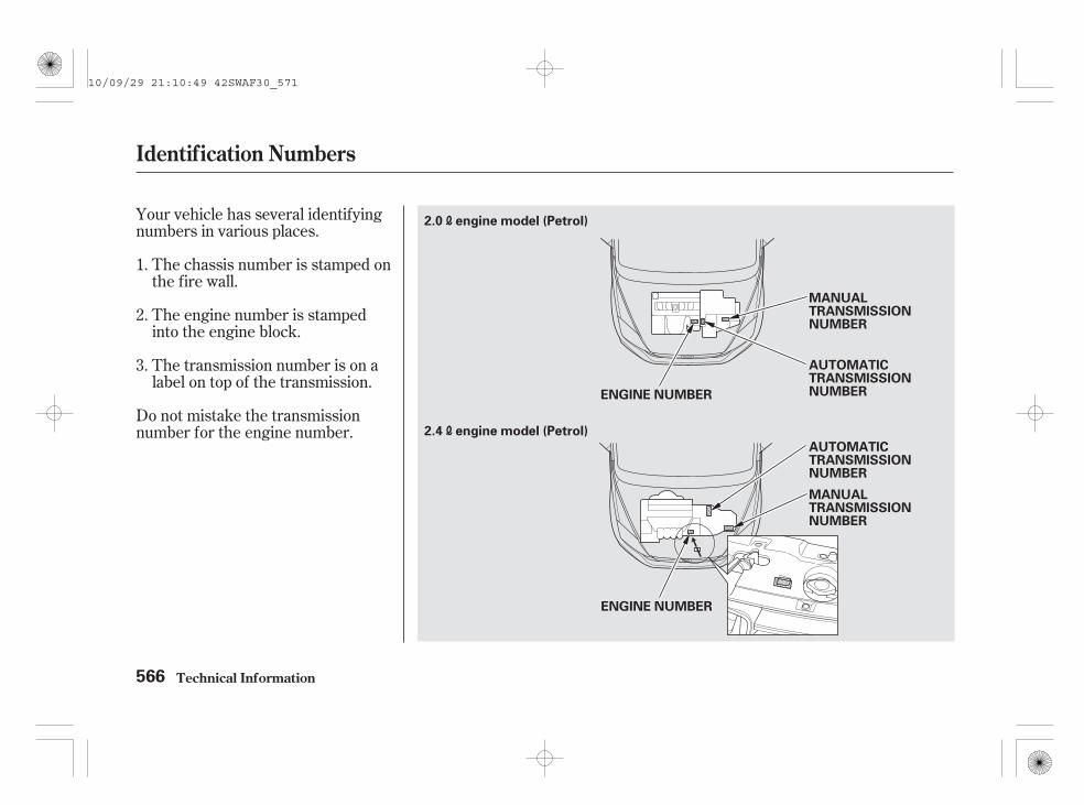
Your vehicle has several identifyingnumbers in various places.
The chassis number is stamped onthe fire wall.
The engine number is stampedinto the engine block.
The transmission number is on alabel on top of the transmission.
Do not mistake the transmissionnumber for the engine number.
1.
2.
3.
Identif ication Numbers
Technical Information566
2.0 engine model (Petrol)
2.4 engine model (Petrol)
AUTOMATICTRANSMISSIONNUMBER
MANUALTRANSMISSIONNUMBER
ENGINE NUMBER
ENGINE NUMBER
AUTOMATICTRANSMISSIONNUMBER
MANUALTRANSMISSIONNUMBER
10/09/29 21:10:49 42SWAF30_571

CONTINUED
Identif ication Numbers
Technical Information 567
2.2 engine model (Diesel)
ENGINE NUMBER
AUTOMATICTRANSMISSIONNUMBER
MANUALTRANSMISSIONNUMBER
10/09/29 21:10:54 42SWAF30_572

The vehicle identification number(VIN)/chassis number is mouldedon the fire wall in the enginecompartment. To access this number,pull down the lid on the back of theengine compartment. Make sure toreinstall the lid before closing thebonnet.
The Vehicle Identification Number(VIN)/chassis number also appearson a plate fastened to the top of thedashboard.
The chassis and engine numbersalso appear on the plate attached tothe front doorjamb on the left side.
Identif ication Numbers
Technical Information568
VEHICLE IDENTIFICATION NUMBER (VIN)
CHASSIS AND ENGINE NUMBER PLATE
This plate includes the following information.Example:
ENGINE NUMBERBlank or WHOLE VEHICLETYPE APPROVAL NUMBERTYPE
TOTAL RUNNING WEIGHT
MAXIMUM PERMISSIBLEWEIGHT
MAXIMUM PERMISSIBLEAXLE WEIGHT (FRONT)MAXIMUM PERMISSIBLEAXLE WEIGHT (REAR)
VIN
10/10/05 18:05:18 42SWAF30_573

*
*
Specifications
Technical Information 569
The mounting point/rear over
hang of coupling device
Dimensions
792 mm (31.2 in)
593 mm (23.3 in)693 mm (27.3 in)
4,570 mm (179.9 in)
1,675 mm (65.9 in)1,820 mm (71.7 in)
410 mm (16.1 in)307 mm (12.1 in)995 mm (39.2 in)1,080 mm (42.5 in)
marks show towbar fixing points.mark shows towbar coupling point.
DimensionsNo.(1)(2)(3)(4)(5)(6)(7)
LengthWidthHeight
WheelbaseTrack
1,585 mm (62.4 in)1,570 mm (61.8 in)2,630 mm (103.5 in)1,805 mm (71.1 in)
NOTE:1.2.
FrontRear
(7)
: With roof antenna(6)
(4)
(2)(3)
(5)
(1)
10/09/29 21:11:19 42SWAF30_574

- -- -
- -- -
- -- -
*
**
*
*
*
*
*
Specifications
Technical Information570
Weights Weights
1,499 1,607 kg (3,305 3,543 lbs)1,534 1,643 kg (3,382 3,622 lbs)
1,567 1,592 kg (3,455 3,510 lbs)1,593 1,633 kg (3,512 3,600 lbs)
1,651 1,712 kg (3,640 3,774 lbs)1,712 1,773 kg (3,774 3,909 lbs)
Curb weight
Max. permissible weight
2,220 kg (4,894 lbs)2,160 kg (4,762 lbs)
2,080 kg (4,586 lbs)2,050 kg (4,519 lbs)
Max. permissible axle weight(Front)
Max. permissible axle weight(Rear)
1,200 kg (2,646 lbs)1,140 kg (2,513 lbs)
1,050 kg (2,315 lbs)1,020 kg (2,249 lbs)
1,040 kg (2,293 lbs)1,040 kg (2,293 lbs)1,040 kg (2,293 lbs)1,050 kg (2,315 lbs)
M/TA/T
See the plate attached to the driver’s doorjamb or ask dealer forinformation.
M/TA/T
2.0 engine
2.4 engine
Diesel engine
1 :
2 :3 :
M/TA/T
M/TA/T
M/TA/T
2.0 /2.4 engine
Diesel engine
2.0 engine model2.4 engine model
2.0 /2.4 engine
Diesel engineM/TA/T
M/T
A/T
M/TA/T
2.0 /2.4 engine
Diesel engine
1
1
1
3
2
10/09/29 21:11:32 42SWAF30_575
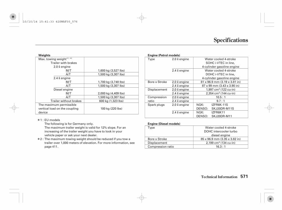
* *
*
*
Specifications
Technical Information 571
Engine (Diesel models)
Engine (Petrol models)Weights
Type
Bore x StrokeDisplacementCompression ratio 16.3 : 1
2,199 cm (134 cu-in)85 x 96.9 mm (3.35 x 3.82 in)
Water cooled 4-strokeDOHC intercooler turbo
diesel engine
Type
Bore x Stroke
Displacement
CompressionratioSpark plugs
Water cooled 4-strokeSOHC i-VTEC in line,
4-cylinder gasoline engineWater cooled 4-strokeDOHC i-VTEC in line,
4-cylinder gasoline engine81 x 96.9 mm (3.19 x 3.81 in)87 x 99 mm (3.43 x 3.90 in)
1,997 cm (122 cu-in)2,354 cm (144 cu-in)
10.5 : 19.7 : 1
IZFR6K-11SSKJ20DR-M11SIZFR6K11SKJ20DR-M11
The maximum trailer weight is valid for 12% slope. For anincreasing of the trailer weight you have to look in yourvehicle paper or ask your next dealer.The maximum towing weight should be reduced if you tow atrailer over 1,000 meters of elevation. For more information, seepage .
600 kg (1,323 lbs)
100 kg (220 lbs)
1,500 kg (3,307 lbs)2,000 kg (4,409 lbs)
1,500 kg (3,307 lbs)1,700 kg (3,748 lbs)
1,500 kg (3,307 lbs)1,600 kg (3,527 lbs)
Max. towing weight
The maximum permissiblevertical load on the couplingdevice
NGK:DENSO:
2.0 engine
2.4 engine
2.0 engine2.4 engine2.0 engine2.4 engine2.0 engine2.4 engine2.0 engine
2.4 engine NGK:DENSO:
The following is for Germany only.EU models1 :
2 :
M/TA/T
M/TA/T
M/TA/T
411
Trailer with brakes2.0 engine
2.4 engine
Diesel engine
Trailer without brakes
1, 2
10/10/14 15:41:33 42SWAF30_576

*
*
*
*
*
*
*
*
Specifications
Technical Information572
Capacities
58 (15.3 US gal , 12.8 Imp gal)Fuel tank
Engine coolant
6.8 (1.80 US gal , 1.50 Imp gal)5.1 (1.35 US gal , 1.12 Imp gal)
6.8 (1.80 US gal , 1.50 Imp gal)5.0 (1.32 US gal , 1.10 Imp gal)
6.2 (1.64 US gal , 1.36 Imp gal)
6.1 (1.61 US gal , 1.34 Imp gal)7.4 (1.96 US gal , 1.63 Imp gal)
7.5 (1.98 US gal , 1.65 Imp gal)
Engine coolant
0.8 (0.21 US gal , 0.18 Imp gal)
Including the coolant in the expansion tank and that remaining inthe engine. Expansion tank capacity:
0.6 (0.16 US gal , 0.13 Imp gal)
Including the coolant in the reserve tank and that remaining in theengine.Reserve tank capacity:
8.1 (2.14 US gal , 1.78 Imp gal)6.9 (1.82 US gal , 1.52 Imp gal)
8.0 (2.11 US gal , 1.76 Imp gal)6.8 (1.80 US gal , 1.50 Imp gal)
Approx.
2.0 engine modelsAutomatic transmission
Manual transmission
2.4 engine modelsAutomatic transmission
Manual transmission
ChangeTotal
ChangeTotal
ChangeTotal
ChangeTotal
1 :
2 :
Diesel modelsAutomatic transmission
Manual transmission
ChangeTotal
ChangeTotal
1
1
1
1
2
2
10/09/29 21:12:00 42SWAF30_577

*
*
*
*
*
*
*
*
*
*
*
*
*
* ***
Specifications
Technical Information 573
Capacities
2.2 (2.3 US qt , 1.9 Imp qt)
2.5 (2.6 US qt , 2.2 Imp qt)3.7 (3.9 US qt , 3.3 Imp qt)3.5 (3.7 US qt , 3.1 Imp qt)4.5 (4.8 US qt , 4.0 Imp qt)
4.2 (4.4 US qt , 3.7 Imp qt)4.0 (4.2 US qt , 3.5 Imp qt)5.3 (5.6 US qt , 4.7 Imp qt)
5.5 (5.8 US qt , 4.8 Imp qt)5.2 (5.5 US qt , 4.6 Imp qt)6.5 (6.9 US qt , 5.7 Imp qt)
2.5 (2.6 US qt , 2.2 Imp qt)
3.1 (3.3 US qt , 2.7 Imp qt)
2.5 (2.6 US qt , 2.2 Imp qt)
Engine oil2.0 engine models
2.4 engine models
Diesel models
7.0 (7.4 US qt , 6.2 Imp qt)2.6 (2.7 US qt , 2.3 Imp qt)
7.9 (8.3 US qt , 7.0 Imp qt)
4.8 (5.1 US qt , 4.2 Imp qt)1.4 (1.5 US qt , 1.2 Imp qt)1.2 (1.3 US qt , 1.1 Imp qt)
Manual transmission fluid
Automatic transmission fluid
Transfer assembly fluid
Rear differential fluid
Windscreen washer reservoir
0.41 (0.43 US qt , 0.36 Imp qt)0.45 (0.48 US qt , 0.40 Imp qt)
ChangeIncluding filterWithout filter
Total
ChangeIncluding filterWithout filter
Total
ChangeIncluding filterWithout filter
Total
1 : Excluding the oil remaining in the engine 2 :3 :4 : Diesel models with automatic transmission
ChangeTotal
Change
Total
ChangeTotal
ChangeTotal
2.0 and 2.4 engine modelsDiesel models
1
1
1
2
3
2
3
2
3
4
4
2
3
10/09/29 21:12:14 42SWAF30_578

-**
*
*
Specifications
Technical Information574
Suspension
Steering
Alignment
Tyres
Brake
Clutch
0.0 mm (0.00 in)
0°
Type
TypeToe-in
Camber
Caster
2.0 mm (0.08 in)
1°2°44’
StrutDouble wishbone
Rack and pinion, with electricalpower assistanceRack and pinion, with hydraulicpower assistance
Size/Pressure See tyre information label ondriver’s doorjamb or ask dealerfor information.
TypeFrontRearParking
Type Dry, single plate, diaphragm spring
MechanicalSolid discVentilated discPower assisted
in
FrontRear
FrontRearFrontRearFront 1 :
2 :2.0 engine model2.4 and Diesel models
1
2
10/09/29 21:12:30 42SWAF30_579

*
*
*
*
*
*
*
*
±
±
*
*
--
-----
-------------
**
*
Specifications
Technical Information 575
Battery Lights
Fuses (Petrol models)
Honda TRK Air Compressor
Jack
Fuses(Diesel models)
Capacity
12 V12 V12 V
21/5 W21 W
5 W21 W
12 V12 V
21 W
12 V 45 AH/20 HR
NOTE:Replacement of the side turn signal light in the outside mirrors should bedone by your dealer.
On vehicles with high voltage discharge type low beamheadlights, replacement of a low beam headlight bulb should beperformed by your dealer.
8 W2 W3.4 W
8 W
5 W55 W21 W
12 V12 V12 V12 V12 V12 V12 V12 V12 V12 V 5 W
60 W55 W35 W
21 W
8 W
12 V12 V12 V
For some types
Headlights
Front turn signal lightsFront position lightsSide turn signal lightsRear turn signal lightsStop/taillightsBack-up lightsTail-lightsRear fog lightFront fog lightsLicence plate lightsHigh-mount brake lightCeiling lightSpotlightsGlove box lightVanity mirror lightsLuggage area light
12 V 74 AH/20 HR
Interior
Under-bonnet(Primary and secondary)
See page 558 or the fuse labelattached to the lower dashboard.See page 557 or the fuse boxcover.
See pages 560 and 561 or the fuselabel attached to the lowerdashboard.See page 559 or the fuse boxcover.
A weighted emission soundpressure levelA weighted sound power level 91.5 5 dB (A)
80 5 dB (A)
Honda Type-EType
Interior
Under-bonnet(Primary and secondary)
(AMBER)
1 :
(H1)
2 :
High beamLow beam
(H11)
(HB3)
(D2S)
(AMBER)See note below.
1 :2 :
2.0 and 2.4 engine modelsDiesel models
: Including auxiliary fuses
2
2
2
1
1
2
10/09/29 21:12:59 42SWAF30_580

The three way catalytic convertermust operate at a high temperaturefor the chemical reactions to takeplace. It can set on fire anycombustible materials that comenear it. Park your vehicle away fromhigh grass, dry leaves, or otherflammables.
Always use unleaded petrol. Even asmall amount of leaded petrol cancontaminate the catalyst metals,making the three way catalyticconverter ineffective.
Catalytic Converters (Petrol models)
Technical Information576
10/09/29 21:13:05 42SWAF30_581

The DPF system requires no regularmaintenance. If you drive for longperiods at slow speeds, particulatematter (PM) will be accumulatedand the regeneration of DPF will berequired. The condition of theaccumulated PM will vary with thetype of diesel fuel. Always use therecommended diesel fuel in thisowner’s manual (see page ).
The PM will be burnt out andremoved from the DPF at aperiodically high temperature of thecatalytic converter while driving.While the PM is burnt, you maynotice some changes on theinstrument panel and the exhaustgas. You may notice some whitesmoke in the exhaust gas. Theaverage fuel consumption on themulti-information display will beincreased temporarily.
Your vehicle is equipped with thediesel particulate filter (DPF) systemto remove the particulate matter(PM) from the exhaust gas. TheDPF is installed in the catalyticconverter.
353
CONTINUED
Diesel Particulate Filter (DPF)System
Catalytic Converters (Diesel models)
Technical Information 577
10/09/29 21:13:12 42SWAF30_582

If you see this symbol or this symbolwith a ‘‘DPF REGENERATIONREQUIRED’’ message on the multi-information display while the engineis running, it means the dieselparticulate filter (DPF) should beregenerated to remove theaccumulated particulate matter (PM).
To regenerate the DPF, when trafficallows, maintain a vehicle speed of atleast 60 km/h (37 mph) and continueto drive until the symbol/messagegoes out (it may take about 15minutes, depending on drivingconditions). This will increase theexhaust temperature and help toburn and remove the PM from theDPF.
If you ignore this symbol/messageand continue driving, the systemwarning switches to the symbol/message of DPF (check system). Ifthis happens, take your vehicle to aHonda dealer as soon as possible tohave the DPF system checked.
DPF (Regeneration Required)
Catalytic Converters (Diesel models)
Technical Information578
10/09/29 21:13:19 42SWAF30_583

If you ignore this symbol/messageand continue driving, the DPF andyour vehicle’s emission controlsystems will be seriously damaged.
The catalytic converter and DPFsystem must operate at a hightemperature for the chemicalreactions to take place. It can set onfire any combustible materials thatcome near it. Park your vehicle awayfrom high grass, dry leaves, or otherflammables.
If you see this symbol or this symbolwith a ‘‘CHECK SYSTEM’’ messageon the multi-information displaywhile the engine is running, it meansthe diesel particulate filter (DPF) isclogged with accumulatedparticulate matter (PM) and itshould be checked, then repaired orreplaced. Take your vehicle to aHonda dealer as soon as possible.While in this condition, the enginepower gets reduced.
DPF (Check System)
Catalytic Converters (Diesel models)
Technical Information 579
10/09/29 21:13:26 42SWAF30_584

580
10/09/29 21:13:29 42SWAF30_585

CONTINUED
................................................AAC . 281...Accessories and Modifications . 363
ACCESSORY (Ignition Key.....................................Position) . 163
............Accessory Power Sockets . 216................Active Head Restraints . 187
..Adaptive Cruise Control (ACC) . 301.......................................Indicator . 94
Adaptive Front Lighting System......................................(AFS) . 153.......................................Indicator . 94
..................................Off Switch . 154........Adding Engine Coolant . 446, 448
...........Additives, Engine Oil . 442, 444.............................Airbag (SRS) . 15, 35
...................................Air Bleeding . 501.............Air Cleaner Element . 457, 460
......Air Conditioning System . 226, 233..............................Maintenance . 479
.................................Usage . 226, 233................Air Outlets(Vents) . 226, 233
......................Air Pressure, Tyres . 486.....Aluminium Wheels, Cleaning . 505
..............................Antifreeze . 446, 448
Anti-lock Brakes (ABS)...............................Indicator . 89, 389
...................................Operation . 389Anti-theft Steering Column
............................................Lock . 163..........................Appearance Care . 503
...........................................Ashtray . 220................................Audio System . 243
...Auto Door Locking/Unlocking . 168
...Automatic Intermittent Wipers . 146Automatic Lighting Feature
...................................Operation . 149.......................System Warning . 149
...Automatic Seat Belt Tensioners . 31..............Automatic Transmission . 381
..........................Capacity, Fluid . 573...............Checking Fluid Level . 451
....................................D3 Mode . 383.......................................Shifting . 381
....................Position Indicators . 381
....................Shift Lock Release . 385......................Auxiliary Input Jack . 290
BatteryCharging System
...........................Indicator . 87, 547............................Jump Starting . 536
..............................Maintenance . 495...................................Replacing . 497
............................Specifications . 575..............................Before Driving . 351
..................................Belts, Seat . 13, 26.........................Beverage Holders . 215
....................Bonnet, Opening the . 356..................................Booster Seats . 72
Brakes...........Anti-lock System (ABS) . 389
.............Break-in, New Linings . 352............Bulb Replacement . 471, 472
...........................................Fluid . 454.......................................Parking . 212
.................System Indicator . 88, 551........................Wear Indicators . 388
.............................Braking System . 388.................Break-in, New Vehicle . 352
Index
A B
581
10/09/29 21:13:35 42SWAF30_586
Brightness Control,...............................Instruments . 155
......................Brights, Headlights . 148Bulb Replacement
..........................Back-up Lights . 471..............................Brake Lights . 471
.......................Front Fog Lights . 475...............Front Position Lights . 470
.................................Headlights . 465.........High-mount Brake Light . 472
...........................Interior Lights . 477.................Licence Plate Lights . 474
..........................Rear Fog Light . 471................................Rear Lights . 471
............................Specifications . 575............Turn Signal Lights . 469, 471
......................Bulbs, Halogen . 465, 475
...................Capacities Chart . 572, 573.............Carbon Monoxide Hazard . 76
.........................Carrying Luggage . 365..............Catalytic Converter . 576, 577
.............CAUTION, Explanation of . iii.........................................CD Care . 269
..........................CD Changer . 256, 266CD Changer Error
...........................Messages . 267, 268.......................................CD Player . 256
.........CD Player Error Messages . 267..................................Ceiling Light . 221................................Chains, Tyres . 493
...................Changing a Flat Tyre . 513Changing Oil
......................................When to . 427...Charging System Indicator . 87, 547
...................Chassis Number . 566, 568............Checklist, Before Driving . 373
..........Child Restraint Systems . 53, 56.....................Lower Anchorages . 58
................Tether Anchor Points . 68.....................................Child Safety . 42
..............................Booster Seats . 72......Child Restraint Systems . 53, 56
Important Safety.............................Reminders . 42, 47
..........................................Infants . 49..........................Larger Children . 71
.....................Lower Anchorages . 58................Risks with Airbags . 43, 46
.............................Small Children . 51
.........................................Tethers . 68.........Where Should a Child Sit? . 43
................Childproof Door Locks . 173..........................Cigarette Lighter . 219
............Cleaner Element, Air . 457, 460Cleaning
...................Aluminium Wheels . 505......................................Exterior . 504.......................................Interior . 507
...................................Seat Belts . 509...........................................Vinyl . 508
....................................Windows . 508...............Climate Control System . 233
..............................................Clock . 293...........................Clutch Fluid . 454, 455
......................................Coat Hook . 218....Cold Weather, Starting in . 374, 375
Collision Mitigation Braking....................System (CMBS) . 391
.......................................Indicator . 95..................................Off Switch . 394
..........................................Radar . 396.....................Compact Spare Tyre . 512
.................Console Compartment . 217.............Controls, Instruments and . 79
....................Conversation Mirror . 218
Index
C
582
10/09/29 21:13:39 42SWAF30_587

CONTINUED
Coolant................................Adding . 446, 448
....................................Checking . 360.................Proper Solution . 446, 448
.................Temperature Gauge . 100....................Corrosion Protection . 510
..............................Courtesy Light . 223................Cruise Control Indicator . 93............Cruise Control Operation . 298
...................................Cup Holders . 215.....................Customized Settings . 112
...............DANGER, Explanation of . iii...................................Dashboard . 2, 80
..............Daytime Running Lights . 149.................................Dead Battery . 536
....................Default Settings . 112, 139..........Deflation Warning System . 404
......Defrosting the Windows . 232, 239
..............Demister, Rear Window . 156.......................Detachable Anchor . 194
.....................................Diesel Fuel . 353.......................Ultra Low Sulfur . 353
...Diesel Particulate Filter (DPF) . 577...............................Symbol . 578, 579
....................................Dimensions . 569.............Dimming the Headlights . 149
Dipstick..........Automatic Transmission . 451
..................................Engine Oil . 358........................Directional Signals . 148
........Disc Brake Wear Indicators . 388.....................................Disc Player . 256
DoorsAuto Door Locking/
..............................Unlocking . 168............Locking and Unlocking . 164
....................Power Door Locks . 164Downshifting
..............Manual Transmission . 377...........Driver and Passenger Safety . 9
...........................................Driving . 371....................................Economy . 362
.........................In Bad Weather . 409.................Off-Road Guidelines . 421
...................................Dual Button . 238...........Dual Deck Luggage Shelf . 200
..................Dust and Pollen Filter . 480........................................D3 Mode . 383
..............................Economy, Fuel . 362Electric Power Steering (EPS)
.......................................Indicator . 91..................................Emergencies . 511
.............Battery, Jump Starting . 536...........Brake System Indicator . 551
...............Changing a Flat Tyre . 513.....Charging System Indicator . 547
..................Checking the Fuses . 554.......Hazard Warning Flashers . 156
...............................Honda TRK . 519............................Jump Starting . 536
.....Low Oil Pressure Indicator . 544Malfunction Indicator
..............................Lamp . 548, 549....................Oil Level Indicator . 545..........Overheated Engine . 540, 542
......................PGM-FI Warning . 550.......................................Towing . 562
........................Tyre Sealant Kit . 519.........................Emergency Brake . 212
....................Emergency Flashers . 156
Index
D
E
583
10/09/29 21:13:45 42SWAF30_588

............................Fabric, Cleaning . 508..........................Fan, Interior . 229, 238
.........................................Features . 225....................Filling the Fuel Tank . 354
Filters........................Air Cleaner . 457, 460
.........................Dust and Pollen . 480.............................................Fuel . 462
...........Flashers, Hazard Warning . 156..................Flat Tyre, Changing a . 513
.....................................Floor Mats . 507Fluids
..........Automatic Transmission . 451..........................................Brake . 454.........................................Clutch . 454
..............Manual Transmission . 453..........................Power Steering . 456
.......................Rear Differential . 454.....................................Transfer . 454
...............Windscreen Washers . 450...................Folding Door Mirrors . 211
..............Folding Rear Seat Down . 190.........Folding Rear Seat Forward . 192
........................Four-way Flashers . 156............................Front Airbags . 15, 35
...........................Front Fog Lights . 151......................................Front Seat . 181............................Adjusting . 181, 182
...................................Airbags . 15, 35
.......................................Heaters . 196.................................................Fuel . 352
...........................Cutoff System . 361.........................................Diesel . 353
......................Fill Door and Cap . 354...........................................Filter . 462.........................................Gauge . 100
.....................Low Fuel Indicator . 97................Octane Requirement . 352
........................Tank, Refueling . 354.....................Fuses, Checking the . 554
Gauges.Engine Coolant Temperature . 100
.............................................Fuel . 100.............................Speedometer . 100
...............................Tachometer . 100Gearshift Lever Positions
..........Automatic Transmission . 381..............Manual Transmission . 376
..............................Glass Cleaning . 508......................................Glove Box . 214
......................Glow Plugs Indicator . 88
......................Emergency Towing . 562Engine
..Coolant Temperature Gauge . 100.........................If It Won’t Start . 534
Malfunction Indicator........................Lamp . 86, 548, 549
Oil Level Indicator..............(Multi-Information) . 545........Oil Pressure Indicator . 87, 544......Oil, What Kind to Use . 442, 444
.......................Overheating . 540, 542............................Specifications . 571
..........Starting (Diesel models) . 374
..........Starting (Petrol models) . 375.............Engine Coolant . 360, 446, 448....................Engine Number . 566, 567...............................e-Pretensioners . 32
......................Event Data Recorders . ii...............................Exhaust Fumes . 76....................Expansion Tank . 360, 448
..................Exterior, Cleaning the . 504
Index
F
G
584
10/09/29 21:13:52 42SWAF30_589

CONTINUED
....Halogen Headlight Bulbs . 465, 475Hands-Free Telephone (HFT)
........................................System . 325............Hazard Warning Flashers . 156
Headlights.....................................Adjuster . 158
........................................Aiming . 465.........Daytime Running Lights . 149
..................High Beam Indicator . 96..........Low Beams, Turning on . 148
......................Reminder Beeper . 148Replacing Halogen
......................................Bulbs . 465.................................Turning on . 148
.......................................Washer . 145............................Head Restraints . 185
.........................................Active . 187.............................Heated Mirrors . 211
...................................Heater, Seat . 196.......Heating and Cooling System . 226
....High Altitude, Starting at . 374, 375...............High-Low Beam Switch . 148..............High-mount Brake Light . 472
...................................Honda TRK . 519
...............................Horn . 3, 6, 142, 143.............................Hot Gas Heater . 242...........................Hydraulic Clutch . 454
Identification Number,...............................Vehicle . 566, 568
Ignition............................................Keys . 160
.........................................Switch . 163......................Immobilizer System . 162
.......Important Safety Precautions . 10.........................................Indicators . 86
...............ABS (Anti-lock Brake) . 89..............................................ACC . 94...............................................AFS . 94
Brake (Parking and Brake............................System) . 88, 551
................Charging System . 87, 547...........................................CMBS . 95
.............................Cruise Control . 93Deflation Warning System
...................................Indicator . 90...............................................EPS . 91
..........Front Fog Light Indicator . 92
...................................Glow Plugs . 88
...................................High Beam . 96........Key (Immobilizer System) . 91
.............................Light Control . 149.....................................Lights On . 96......................................Low Fuel . 97
................Low Oil Pressure . 87, 544Malfunction Indicator
........................Lamp . 86, 548, 549.....................................Oil Level . 545......................................PGM-FI . 550
...........Rear Fog Light Indicator . 92.......................................Seat Belt . 86
.........Security System Indicator . 97Shift Up/Shift Down
.................................Indicators . 98...............................................SRS . 89
.........................System Message . 89..............Trailer Stability Assist . 419
Turn Signal and Hazard...................................Warning . 96
.......................................VSA . 92, 402....................VSA Activation . 93, 402
..................Water in Fuel Filter . 462
Index
H
I
585
10/09/29 21:13:57 42SWAF30_590

................................................Keys . 160
...Indicators, Instrument Panel . 82, 86...............................Infant Restraint . 49
......................................Infant Seats . 49.....................Lower Anchorages . 58
................Tether Anchor Points . 68..................Inflation, Proper Tyre . 486
.................................Inside Mirror . 209............................Inspection, Tyre . 488.......................Instrument Panel . 82-85
......Instrument Panel Brightness . 155...........................Interior Cleaning . 507
...............................Interior Lights . 221........................................Introduction . i
.................................................iPod . 272
.................Jacking up the Vehicle . 515......................................Jack, Tyre . 515
................................Jump Starting . 536
...............Lane Change, Signaling . 148......................Language Selection . 138..................Lap/Shoulder Belts . 21, 29
Lights....................Bulb Replacement . 463
.................................Indicator . 82, 86......................................Position . 148
................................Turn Signal . 148....................................Load Limits . 366
....LOCK (Ignition Key Position) . 163.........................Lockable Retractor . 63
Locks.....Anti-theft Steering Column . 163
............................Fuel Fill Door . 354..................................Glove Box . 214
...............................Power Door . 164......................................Tailgate . 179
........................Low Coolant Level . 360.........................Low Fuel Indicator . 97
...Low Oil Pressure Indicator . 87, 544.........................Lower Anchorages . 58
...Lower Gear, Downshifting to a . 376Lubricant Specifications
..........................................Chart . 572
.....................Luggage Area Light . 222.............................Luggage Hooks . 368
................Luggage, How to Carry . 365...............................Luggage Shelf . 200
..........................Luggage, Storing . 365
..................................Maintenance . 425Owner’s Maintenance
...................................Checks . 428..........................................Safety . 426
....................................Schedule . 427Malfunction Indicator
............................Lamp . 86, 548, 549...................Manual Transmission . 376
........Manual Transmission Fluid . 453Maximum Allowable Shift
........................................Speeds . 378...Maximum Permissible Weight . 570
.........................Meters, Gauges . 82, 99........................Mirrors, Adjusting . 209
...............Modifying Your Vehicle . 364................................................MP3 . 258
...........Multi-Information Display . 101
Index
J
K
L
M
586
10/09/29 21:14:05 42SWAF30_591

CONTINUED
.....................Neutral (N) Position . 383..................New Vehicle Break-in . 352
...................NOTICE, Explanation of . iNumbers,
.............Identification . 566, 567, 568
Octane Requirement,..........................................Petrol . 352
.......................................Odometer . 105.............................Odometer, Trip . 105
.....................Off-Road Guidelines . 421Oil
......................Change, When to . 427
......................Checking Engine . 357..........................Level Indicator . 545
..............Pressure Indicator . 87, 544Selecting Proper Viscosity
..............................Chart . 443, 445Oil Level Indicator
..................(Multi-Information) . 545.........ON (Ignition Key Position) . 163
..................One-push Turn Signal . 148
............................Outside Mirrors . 210Outside Temperature
.....................................Indicator . 106............Overheating, Engine . 540, 542
....Owner’s Maintenance Checks . 428
..............................Paint Touch-up . 506............Panel Brightness Control . 155
...........................................Parking . 387...............................Parking Brake . 212
Parking Brake and Brake.................System Indicator . 88, 551
Parking Over Things That............................................Burn . 387
................Parking Sensor System . 319...................................Indicators . 319
..........................Park (P) Position . 382..............................................Petrol . 352
................Filling the Fuel Tank . 354...........................................Filter . 462
...........................Fuel Economy . 362.........................................Gauge . 100
.....................Low Fuel Indicator . 97................Octane Requirement . 352
....................................Refueling . 354..........................PGM-FI Warning . 550
..................Polishing and Waxing . 504...................................Pollen Filter . 480
..............................Position Lights . 148........................Power Door Locks . 164
..............Power Seat Adjustments . 181............................Power Windows . 203
.........Pregnancy, Using Seat Belts . 24...........Primary Display Selection . 132
.............Priming the Fuel System . 501..................Proper Seat Belt Usage . 21
.........Protecting Adults and Teens . 17...Additional Safety Precautions . 24
.....Advice for Pregnant Women . 24........................Protecting Children . 42.......................Protecting Infants . 49
.......Protecting Larger Children . 71.........Protecting Small Children . 51
Using Child Restraint Systems............................with Tethers . 68
..........Using Lower Anchorages . 58
Index
N
O
P
587
10/09/29 21:14:11 42SWAF30_592

...........Radiator Overheating . 540, 542...........Radio/Disc Sound System . 243
.................................................RDS . 248.................Rear Differential Fluid . 454
......................Rear Fog Light . 150, 151Rear Lights, Bulb
..............................Replacement . 471........................Rear Seat Armrest . 184................Rear Seat, Folding . 190, 192
...........................Rearview Mirror . 209..........................Rearview Camera . 324
...............Rear Window Demister . 156.....................................Rear Wiper . 147
.....Reclining the Seat Backs . 181, 182.......................Reminder Indicators . 86
................Remote Audio Controls . 289.....................Remote Transmitter . 174
Replacement Information........Air Cleaner Element . 457, 460
.......................................Battery . 497..............Dust and Pollen Filter . 480
..................................Fuel Filter . 462..........................................Fuses . 554
................................Light Bulbs . 463
....................................Schedule . 427................................Spark Plugs . 571
..........................................Tyres . 491.............................Wiper Blades . 482
Replacing Seat Belts After a............................................Crash . 33
Reserve Tank, Engine.......................Coolant . 360, 446, 448
...............................Restraint, Child . 42...........................Reverse Lockout . 380
....................Reverse (R) Position . 382......................................Roof Rack . 367
...............................Rotation, Tyre . 489
................................Safety Belts . 13, 26...............................Safety Features . 12
.........................................Airbags . 15.....................................Seat Belts . 13
.............Safety Labels, Location of . 77..............................Safety Messages . iii
...................................Seat Belts . 13, 26...............Additional Information . 26
Automatic Seat Belt...............................Tensioners . 31
.....................................Cleaning . 509...................Detachable Anchor . 194
...........................e-Pretensioners . 32................Lap/Shoulder Belt . 21, 29
................................Locking Clip . 67
................................Maintenance . 33Reminder Indicator and
................................Beeper . 26, 86...................System Components . 26
...............Use During Pregnancy . 24..................................Seat Heaters . 196
...............Seats, Adjusting the . 181-183..................Driver’s Power Seat . 181
............................Security System . 295...........................Service Intervals . 427
.........Service Station Procedures . 354..........................Setting the Clock . 293
..............................Side Airbags . 15, 38...How Your Side Airbags Work . 38
........................Risks to Children . 46................Side Curtain Airbags . 15, 38
.............................Signaling Turns . 148....................................Snow Tyres . 492
...................Solvent-type Cleaners . 504................................Sound System . 243
Index
R
S
588
10/09/29 21:14:16 42SWAF30_593

CONTINUED
.............................Spare Tyre . 512, 513
.....................................Compact . 512..............................Inflating . 486, 512
............................Specifications . 574....................................Spark Plugs . 571
....................Specifications Charts . 569..................................Speed Alarm . 116.................................Speedometer . 100
Speed-sensitive Volume...............Compensation (SVC) . 255
.......................................Spotlights . 221..........SRS, Additional Information . 35
...Additional Safety Precautions . 41How the SRS Indicator
.......................................Works . 39How Your Front Airbags
.........................................Work . 36........................SRS Components . 35
..................................SRS Service . 41.............................SRS Indicator . 39, 89
..START (Ignition Key Position) . 163..............Starting the Engine . 374, 375
In Cold Weather at High..........................Altitude . 374, 375
................With a Dead Battery . 536
Steam Coming from................................Engine . 540, 542
Steering Wheel..............................Adjustments . 159
...........Anti-theft Column Lock . 163...................Stereo Sound System . 243....................Storing Your Vehicle . 499
...........................................Sunroof . 205......................................Sunshades . 207
.......................Super Locking . 167, 175Supplemental Restraint
................................System . 15, 35
......................................Servicing . 41.........................SRS Indicator . 39, 89
...................System Components . 35....System Message Indicator . 89, 108
System Warning Symbols,.......Multi-Information Display . 107
...................................Tachometer . 100..........................................Tailgate . 179
............................Open Indicator . 17......................................Opening . 179
.....Tail-lights, Changing Bulbs in . 471
.Taking Care of the Unexpected . 511Technical Descriptions
..........Catalytic Converter . 576, 577.....................Temperature Gauge . 100
........Temperature, Inside Sensor . 241.....................Tether Anchor Points . 68
..........................Time, Setting the . 293..............................Tonneau Cover . 197
..................Tools, Tyre Changing . 514Towing
.....................................A Trailer . 411................Emergency Wrecker . 562
Equipment and Accessories.................Weight Limit . 411, 412
..............Trailer Stability Assist . 419....Trailer Hitch Mounting Points . 569
.....................Trailer Loading . 411, 412..................Trailer Stability Assist . 419
.....................................Indicator . 420......................Trailer Towing Tips . 416
.............Transfer Assembly Fluid . 454
Index
T
589
10/09/29 21:14:22 42SWAF30_594

.........................Ultrasonic Sensor . 297.....................Underside, Cleaning . 510
Unexpected, Taking Care..........................................of the . 511
.....................Upholstery Cleaning . 507..............USB Adapter Cable . 274, 282
.........USB Flash Memory Device . 279
............WARNING, Explanation of . iii.........Warning Labels, Location of . 77
........................Washer, Headlight . 145Washer, Windscreen
........Checking the Fluid Level . 450...................................Operation . 144
.........................................Washing . 504.............................Water Draining . 462
.....................................Indicator . 462..................Waxing and Polishing . 505
Wheels.............Adjusting the Steering . 159............Alignment and Balance . 489
.....Cleaning Aluminium Alloys . 505..........................Compact Spare . 512
...............................Nut Wrench . 515Windows
.............................Auto Reverse . 204.....................................Cleaning . 508
................Operating the Power . 203..........................Rear, Demister . 156
Transmission..................Fluid Selection . 451, 453
......Identification Number . 566, 567.............Shifting the Automatic . 381
..................Shifting the Manual . 376.....................................Treadwear . 488
..............................Trip Computer . 104.....................................Trip Meter . 105
..................................Turn Signals . 148...........................Tyre Chains . 493, 494
........Tyre, How to Change a Flat . 513..............................................Tyres . 486
..............................Air Pressure . 486........................................Chains . 493
.........................Checking Wear . 488..........................Compact Spare . 512
......................................Inflation . 486..................................Inspection . 488
..............................Maintenance . 489...................................Replacing . 491
......................................Rotating . 489...........................................Snow . 492
....................Specifications . 492, 574.TRK (Temporary Repair Kit) . 519
................................Vanity Mirror . 219.................Vehicle Capacity Load . 366
......................Vehicle Dimensions . 569Vehicle Identification
......................Number . 566, 567, 568Vehicle Stability Assist (VSA)
........................................System . 402.............................Vehicle Storage . 499
.............................Ventilation . 226, 233.................................................VIN . 568
...............................Vinyl Cleaning . 508.........................Viscosity, Oil . 443, 445
Index
U
V
W
590
10/09/29 21:14:28 42SWAF30_595

WindscreenAutomatic Intermittent
....................................Wipers . 146.............................Cleaning . 145, 508.....................................Washers . 145
.................................Winter Tyres . 492Wiper Blades
....................................Changing . 482...................................Operation . 144
..............................................WMA . 258...................................Worn Tyres . 488
.....Wrecker, Emergency Towing . 562
Index
591
10/09/29 21:14:31 42SWAF30_596

+
‘‘EC Declaration of Conformity’’ Content Outline
Declaration of ConformityThe Council Directive 2006/42/EC MachineryDeclare in sole responsibility that the equipmentDesignation of Machinery: Pantograph JackModel: SNB, SJD, S2A, SAHType: Honda Type-A, Honda Type-B, Honda Type-C, Honda Type-DIs herewith confirmed to comply with the requirements set out in the Council Directive 2006/42/EC.For the evaluation of compliance with the directive, the following standards were applied:EN1494:2000 A1:2008 according to Annex I of 2006/42/EC.Technical File Compiler: Honda Motor Europe Ltd. Aalst Office wijngaardveld1 (Noord V), 9300 Aalst, Belgium
Note: This declaration becomes invalid, if technical or operational modifications are introduced without the manufacturers consent.Names and Signature:
Type; Honda Type-A, Honda Type-B, Honda Type-CRIKENKAKI CO.,LTD.5-6-12 Chiyoda Sakado-shi, Saitama 350-0214 JAPAN
Type; Honda Type-DCHANGZHOU RIKENSEIKO MACHINERY CO.,LTD.No.1903 Zhongwu Ave. Zhonglou Changzhou, Jiangsu CHINA
Date and Place:01.12.2009 Saitama/JAPAN
President
This declaration is based on:Third party testing performed by the Notified Body TUV Rheinland, Product Safety GmbHRegistration Number: AM50100492 0001/JAPAN (MODEL SNB, SJD, S2A).
AM50118203 0001/CHINA (MODEL SAH).TUV Rheinland Technical Report No.: 1213870 001-002/JAPAN.
15025133 001/CHINA
10/09/29 21:14:36 42SWAF30_597