(this is a sample cover image for this issue. the actual ...extev.syros.aegean.gr/papers/j41.pdf ·...
TRANSCRIPT
(This is a sample cover image for this issue. The actual cover is not yet available at this time.)
This article appeared in a journal published by Elsevier. The attachedcopy is furnished to the author for internal non-commercial researchand education use, including for instruction at the authors institution
and sharing with colleagues.
Other uses, including reproduction and distribution, or selling orlicensing copies, or posting to personal, institutional or third party
websites are prohibited.
In most cases authors are permitted to post their version of thearticle (e.g. in Word or Tex form) to their personal website orinstitutional repository. Authors requiring further information
regarding Elsevier’s archiving and manuscript policies areencouraged to visit:
http://www.elsevier.com/copyright

Author's personal copy
Computer-Aided Design 43 (2011) 1814–1828
Contents lists available at SciVerse ScienceDirect
Computer-Aided Design
journal homepage: www.elsevier.com/locate/cad
A parametric feature-based approach to reconstructing traditional filigreejewelry✩
V. Stamati a, G. Antonopoulos a, Ph. Azariadis b, I. Fudos a,∗
a Department of Computer Science, University of Ioannina, Greeceb Department of Product and Systems Design Engineering, University of the Aegean, Greece
a r t i c l e i n f o
Article history:Received 23 July 2010Accepted 6 July 2011
Keywords:Filigree jewelryParametric designJewelry patternsFeature-based reconstructionRe-engineeringBraids
a b s t r a c t
This paper presents a novel approach to reconstructing traditional filigree jewelry. Our method aims atproducing an editable CAD representation that can accurately capture the original design and be capableof re-parameterization and modification prior to manufacturing (for example to insert custom designsand abide to free-form artistic alterations). To achieve this, we have developed robust and accuraterepresentations of patterns, used in the design of such jewelry, based on spirals, circular and ellipticarcs, curve segments and braids of various types; all optimized by fairness criteria for aesthetic purposes.We have also built a library of parametric, constraint-based, manufacturable solid patterns that occurfrequently in filigree jewelry. For the purposes of thiswork, a suite of software tools calledReJCADhas beendeveloped, that is able to process a highly accurate point cloud of jewelry pieces and to detect featureswhich are fitted by the primitives of the pattern library through user interaction. The point cloud, in thecurrent framework, guides the assembling of all patterns into one robust manufacturable solid piece. Wedemonstrate the unique capabilities of ReJCAD by reconstructing a filigree brooch part commonly used inlate 19th century in northwestern Greece.
© 2011 Elsevier Ltd. All rights reserved.
1. Introduction
Computer Aided Design (CAD) systems are widely used in mostindustries and are increasingly used in jewelry manufacturing[1,2]. While manual design of jewelry is still in wide use,this approach is both cumbersome and time consuming whencompared to designing using 3D CAD systems.
Editing and redesigning are feasible in a 3D CAD environment,as long as they are supported by parametric and constraint-basedtechniques [3,4]. 3D rendering helps the artist to detect parts ofthe model that are unsatisfactory [5]. In addition, it is possibleto redesign based on customer feedback after browsing the firstversion. Generally, current feature-based systems include varioustools to assist in designing a piece of jewelry, including constraints,transformations, libraries of jewelry parts and other solid patternssuch as cut stones and gems.
Despite the effectiveness of current 3DCAD systems for jewelry,there are categories of jewelry that cannot be reconstructed evenwith modern CAD systems. Examples of such types of jewelry are
✩ This work was partially supported by Eureka Project #3506, REJCAD under asubcontract for the Hellenic Center of Gold Silversmiths Trade.∗ Corresponding author. Tel.: +30 26510 98805; fax: +30 26510 98881.
E-mail address: [email protected] (I. Fudos).
traditional pierced jewelry, filigree jewelry and modern jewelryof free-form design. Filigree jewelry is made using a techniqueof twisting, bending, wrapping and braiding plain precious metalwires (gold and silver) to create a lace-like effect of pierced jewelry(Fig. 1). The metalwork is often combined with precious stones,crystals or glasses to create both jewelry and non-jewelry artifacts.Standard forms of jewelry produced in filigree are earrings,bracelets, brooches, pendants, chains, necklaces and buttons.
Findings in the Valley of the Kings [6] suggest that thistechnique was first used by ancient Egyptians. Wires of variablediameter were often used either to decorate precious metalsurfaces or to craft an entire jewelry piece. From Egypt the filigreetechnique spread to ancient Greece and Europe and reached Persiaand India [7]. In Tibet it was extensively used to decorate the innerparts of the traditional ga’u pendants which the Tibetans used asamulets or charms or credentials of authority [7]. Fig. 2 portraitsthe use of the filigree technique in such jewelry pieces. The filigreetechnique flourished and India still remains a massive producer offiligree based jewelry.
Filigree is a technique that produces impressively elaborateartifacts, which combine elegance with the aura of tradition. Itbecame widespread, not only due to its elaborate and yet delicateresults, but also because it allows for the creation of maximumsize objects by consumption of a minimal amount of preciousmetal. However it is very delicate, tedious and time-consuming,properties which have forced local Mediterranean craftsmen to
0010-4485/$ – see front matter© 2011 Elsevier Ltd. All rights reserved.doi:10.1016/j.cad.2011.07.002

Author's personal copy
V. Stamati et al. / Computer-Aided Design 43 (2011) 1814–1828 1815
Fig. 1. A filigree brooch.
refrain from its use. This raised the need for a procedure thatwoulddiminish the time consumed and remove the bulk of the labor ofthis technique.
In this paper, we present a novel approach to reconstructing,creating, and customizing jewelry of filigree craftsmanship (Fig. 1).A suite of CAD tools called ReJCAD has been developed, providingthe means to the end user to digitally reconstruct, personalizeand manufacture filigree-type jewelry using parametric andfeature-based techniques. More specifically, this paper makes thefollowing technical contributions:
• Introduces a representation scheme for modeling filigreepatterns using elliptical arcs, Bezier segments, spirals and othercurve segments. Geometric constraints are imposed on themodel in the underlying filigree design library to provide thenecessary robustness, editability, and aesthetic conformity totraditional design patterns.
• Describes a novel approach to modeling braids using rationalBezier curve segments which yields an aesthetically improvedclass of braids.
• Presents a partially automated re-engineering process that aidsthe reconstruction of a CADmodel of traditional filigree jewelryusing information derived from a point cloud acquired by highprecision 3D scanning.
The remainder of this paper is structured as follows. Section 2summarizes the current state of art on the open problemsthat have been tackled in this work. Section 3 presents theproposed classification of parametric constraint-based patterns forcreating editable 3D models of filigree jewelry; it also presentsa new approach to modeling braids of strands using rationalBezier curves. Section 4 describes the process of re-engineeringand reconstructing jewelry pieces, whereas Section 5 presentsevaluation results: an example case, a usability evaluation and
examples of actually manufactured jewelry. Finally, Section 6offers conclusions.
2. Related work
CAD tools are being usedmore andmore in artistic and aestheticapplications. In these applications the aim is not only to realizecertain geometries and patterns but a main concern is the overallaesthetic result. Examples serving this purpose are presentedin [8,9], where parametric sculpture generators are implementedto create and modify artifacts belonging to certain conceptualfamilies, and to evaluate the final aesthetic result. In [10] anapplication concerning kinetic art, i.e., art that involvesmovement,is presented. A system is proposed for designing original kineticart objects where a 3D geometric-modeling interface and a rigid-body simulation are combined. A survey on CAD methods used inanother aspect of artistic expression, garment design, is providedin [11].
Jewelry design and construction is another example of com-bining CAD tools and aesthetics. Various commercial softwarepackages have been developed for designing and creating CADjewelry models such as JewelCAD [12], Rhino3D [13], ArtCAMJewelSmith/Delcam Designer [14], Matrix 3D Jewelry Design Soft-ware [15] and 3Design CAD [16]. Most of these systems providesome form of parametric and feature-based capabilities, graphicalinterfaces with excellent rendering capabilities, built-in librariesfocused on jewelry design that include different piece settings, cutgems and stones, and advanced feature-based design tools. Somesystemsprovide advanced functionality, such asMatrix [15],whichoffers the use of builders for recording design steps and for definingparameter values for parts to be used in the process. Also, the ma-jority of these systems have the capability of exporting models torapid prototyping machines. All of these systems provide varioustools formaking jewelry design a simpler and less time-consumingprocess.
These software packages are convenient for designing andcreating various forms of generic style jewelry. However, none ofthese systems is appropriate for designing and creating editableCAD models of jewelry of a particular craftsmanship, such asfiligree jewelry. In particular, for constructing this type of jewelry,where the fine aesthetic result is achieved through twisting,bending and combining wire strands to create complex designs,a system is required that provides the capability to: (i) createvery accurate and robust solid models ready for reproduction,(ii) create parametricmodels of filigree jewelry that can be used forcustom design and redesign and (iii) incorporate filigree designsinto a solidmodel corresponding to a ring, bracelet, necklace, etc. Inmost commercial CAD systems for jewelry, designing is performedmanually using various tools and usually the design steps cannotbe programmed to be executed automatically and accurately. Thismeans that each different piece of pierced jewelry would have to
a b c
Fig. 2. Silver ga’u ornamented with (a) gold, (b) silver filigree [7], and (c) detail of a golden filigree necklace [7].

Author's personal copy
1816 V. Stamati et al. / Computer-Aided Design 43 (2011) 1814–1828
be created basically from the beginning by hand which does notconform to the requirement of redesign capability. Editing is thenusually achieved through history rollback, by returning to a priordesign state of themodel and applyingmodifications to themodel.
Another CAD approach to designing and producing jewelry ofa particular craftsmanship is ByzantineCAD [17]. ByzantineCAD isan automated, parametric CAD system for designing and producingpierced Byzantine jewelry where the user-designer sets someparameter values and ByzantineCAD creates the jewelry modelthat corresponds to the specified values. This provides the designerwith the capacity to rapidly create custom-designed jewelry, basedon the preferences of the customers. ByzantineCAD introducesa feature-based and voxel-based approach to designing jewelry,through the definition of elementary structural elements withspecific attributes that are used as building blocks to constructcomplex pierced designs. Modern free-form jewelry can onlybe partially described through predefined primitives and featurelibraries, due to its abstract and artistic nature which is oftendifficult to capture. It is usually created using curves (such asNURBS) and surfacemodeling techniques. An alternative approachto reconstructing free-form artifacts is presented in [18].
A parametric approach to creating carved jewelry is alsopresented in [19]. Voxel elements are constructed and combined torecreate jewelry depicting designs made from small carvings. Thissystem provides both design and rapid prototyping capabilities.In [20] a parametric–feature-based jewelry modeler for designingand manufacturing Fret-worked bangles is presented. Fretworkdesigns are encoded as features that are recurrently removed fromstock-solid bangles. Finally, Kai et al. [21] developed a reverseengineering system for re-engineering rings. This method createsbasic generic models of the initial ring object. To manufacture thering, the 3D model is transformed into a 2D representation onwhich the engraving of the ring design will be performed. Thismethod is appropriate for creating blank generic models of ringsthat a designer will then use to create his/her own ring model.
In general, editing parts of filigree designs in commercialjewelry design systems requires in depth knowledge of feature-based design and solid modeling techniques. In contrast, oursystem offers an easy, semi-automated procedure for creatingand customizing jewelry featuring filigree designs. In our systemone defines the basic parameters that refer mostly to theappearance, size and content of the final product and then theconstruction of the specified model is carried out by the system.By parameterizing the process of creating filigree jewelry, it iseasy to modify characteristics of the jewelry such as the size andthe designs represented. Furthermore, designing a piece of filigreejewelry using a traditional CAD system may lead to models withrobustness problems, which are inappropriate for manufacturing,creating therefore the need for repairing tools and techniques. Thetechnique used in our system leads to robust models that canbe directly sent to rapid prototyping machines for manufacturingwithout any further intervention or repair.
3. Identifying and reconstructing filigree features
Through studying the design of a series of filigreemade jewelry,particularly those made by local craftsmen in northwesternGreece, we have concluded that certain primordial patterns arebeing used repeatedly in various combinations. Examples offiligree patterns are shown in Fig. 3. By studying the craftsmanshipof filigree jewelry, a core set of patterns that are used as buildingblocks in a wide range of filigree designs is identified.
In this Section, we report on the characteristics of wire strands(which are the building elements of filigree jewelry) and severalcommon elementary features observed in filigree jewelry. Finally,
Fig. 3. Various design elements observed in filigree jewelry [7].
we report on the composition of more complex designs that arecommonly used in this type of craftsmanship.
The following issues are considered central to achievingaesthetically acceptable filigree components:
• Derive a variety of wire strands and braids which are thebuilding blocks of filigree jewelry.
• Combine elliptical arcs and/or circular arcs with two or moreinscribed spirals of equal spacing.
• Use scaled patterns as subpartsmaintaining certain parameters.
Finally, in our models, wires are allowed to slightly overlapeach other to enforce coherency. Wire overlapping is consideredcritical for manufacturability (during both 3D printing/layeredmanufacturing and casting) and does not affect the aesthetics ofthe final jewelry piece, if it remains within reasonable bounds.Experienced craftsmen and artists have determined that the edgesof the resulting jewelry piece are even sharper than the originalpiece because of the gluing material used by the craftsmen infiligree jewelry. To have better control of the design sharpnesswe provide a parameter that affects the thickness of all the wiresinvolved in feature construction by a small percentage (up to±10%).
3.1. Wire strands, basic shapes and features
The basic idea behind filigree craftsmanship is to twist andbend strands of wires to build complex designs. Certain properties(parameters) stand out regarding the wires used to build anddecorate a filigree jewelry piece: wire strand geometry (thicknessand length), the number of wire strands and the technique ofcombining strands to create larger decorative and more complexstrands.
An elliptic shape, an ellipsoid, a circle or a sphere can be usedeither as an outline of a jewelry part or as a solid base onwhich thefiligree design will be applied. Archimedean or logarithmic spiralsare inscribed inside basic shape constructs. Rows 1 through 3 ofTable 1 summarize the different types ofwire strand combinations.Rows 4 through 6 illustrate combinations of elliptical arcs, circulararcs and line segments while the last rows summarize nested andinscribed patterns. For amore detailed description of all constructsthe reader is referred to [22].
3.2. Braids revisited
Braided strandsare built by sweeping a circle along a pathcurve (see Table 1). We have used cubic rational Bezier curvesto realize braid strand path curves, a choice that offers a widerrange of parameters and essentially better aesthetic results thanthe traditional sinusoidal braid modeling approach. Our braidapproach is a set of four such curves, which are pair-wisesymmetric. For cubic rational Bezier curves with control pointsPm(t),j and weights wm(t),j with m(t) being the curve index and j

Author's personal copy
V. Stamati et al. / Computer-Aided Design 43 (2011) 1814–1828 1817
Table 1Wire strands, basic shapes and features.
Description and construction Parameters and constraints Example
Twisted wire strands: are built by one or more helicalstrands following the same direction, derived bysweeping a circle on a helical spiral curve: C(t) =r cos(t + θ) r sin(t + θ) ct
T, t ∈ [0, ∞]
r (the radius of the helix) and c (the pitch of thehelix), distance d between the paths of two adjacentstrands which is at least d = c/n, n is the number ofwire strands. The radius of each strand should beslightly larger than d
2 .
Intersecting wire strands: are formed by combiningtwo or more pairs of twisted strands. Each pair isconstructed by a strand following a helical curveand a strand following the same helical curve withthe same parameters but wound in the oppositedirection.
Number of pairs, r (the radius of the helix), c (thepitch of the helix), distance d between the paths oftwo adjacent strands, which is at least d = c/n, n isthe number of wire strands. The radius of eachstrand should be slightly larger than d
2 .
Braided strands are built by sweeping a circle along apath curve. Braiding can be performed on three ormore strands. In filigree jewelry three strands aremost often used. In the traditional sinusoidalapproach each strand follows a Lissajous curvewhich is described by: C(t) =r cos(t + k) r sin 2(t + k) ct
T t ∈ [0, ∞]
c (the pitch), r (the radius of the helix) and k whichdefines the displacement of the strand. By scalingand/or modifying the wire thickness of the strands,a different aesthetic result is obtained. For ananalysis of the parameters and constraints see [23].
Round Teardrop: is constructed by uniting half anellipse and a semicircle whose centers coincide. G1
and G2 continuity are preserved everywhere exceptat the joints where only G1 continuity is preserved.Teardrop shapes are mainly used as borders ofseveral kinds of designs and patterns. Multipleteardrops are combined to create more complexdesigns.
b (the overall height), a2 + R (the overall width). The
constraint which is applied to guarantee G1
continuity at the joints is b = 2R.
Pointy Teardrop: is created by connecting a circulararc with two line segments that originate from Tand are tangent to the circular arc at the endpointsS1 and S2 , as shown in the example. S1 and S2 arederived from d, r and C .
distance d of the center of the circular arc from T ,the radius r . G1 continuity is preserved everywhereexcept at the tip of the teardrop. G2 continuity ispreserved everywhere except at the tip and at theendpoints S1 and S2 .
Peacock patterns: To create a peacock-like pattern,pointy teardrops are scaled and placed adjacentlywith a common tip point. In this work, the peacockdesign consists of m pointy teardrops which aresequentially placed within a center angle a of avirtual circle C1 . Given the center angle a, eachpointy teardrop shape si is placed within acontained angle ϕ = a/m. To create each pointyteardrop shape, we use lines li and lj dividing C1 intothe corresponding segment as edges for theteardrop and an arc created from the intersectionpoints of C1 , li and lj . To create teardrops of differentlengths we assume more virtual circles Ck of radiusrk and use their intersecting points with therespective line segments.
The angles ai formed by the line segments are thenequal; however different patterns can be derived byusing different configurations for each peacock‘‘feather’’. : the number of teardrop segmentsm, thecenter angle a, the pattern reference point P(x, y, z)which is the center of the virtual circle C1 and theradius r1 of C1 , which defines the actual size of thepeacock and the teardrop segments. For this patternto be robust, the following constraints must hold:Point P is common for all pointy teardrops andm
i=1 ϕ = a.
Nested Teardrops: This pattern is created by definingn concentric circular arcs of radius ri such thatr1 > r2 > · · · > rn and n rational cubic Beziercurves with start and end points coinciding with thestart and end points of the respective circular arcs.The (n + 1) − th curve is defined to be a circle.
The wire strand style (simple, braided, intersectingpairs etc.) and thickness, the number of nestedteardrops n, the center C(x, y, z) of the n concentricarcs and the distance d0 between the circle (C, rn+1)
and the tip of largest rational Bezier curve whichaffects the inner gap and is aesthetically important.The maximum number of teardrops n of wire strandthickness t that can be nested is n = d0/t .
Author's personal copy
1818 V. Stamati et al. / Computer-Aided Design 43 (2011) 1814–1828
Table 1 (continued)
Description and construction Parameters and constraints Example
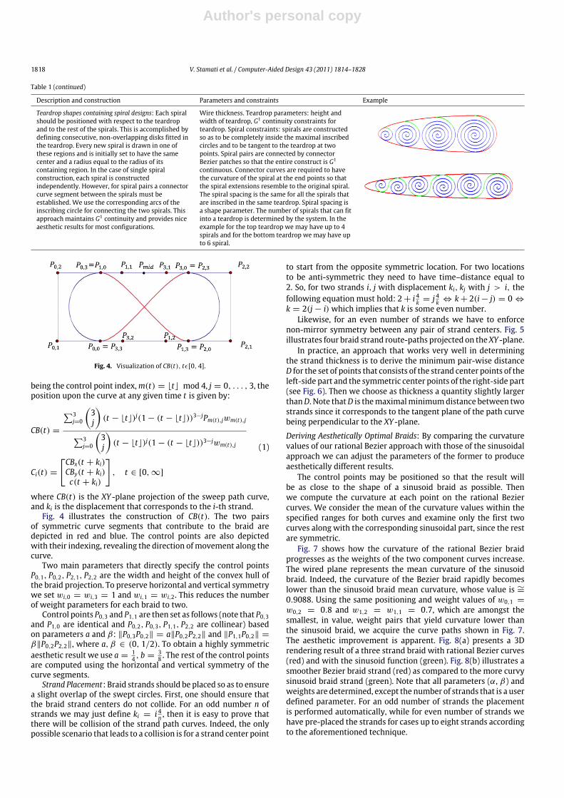
Teardrop shapes containing spiral designs: Each spiralshould be positioned with respect to the teardropand to the rest of the spirals. This is accomplished bydefining consecutive, non-overlapping disks fitted inthe teardrop. Every new spiral is drawn in one ofthese regions and is initially set to have the samecenter and a radius equal to the radius of itscontaining region. In the case of single spiralconstruction, each spiral is constructedindependently. However, for spiral pairs a connectorcurve segment between the spirals must beestablished. We use the corresponding arcs of theinscribing circle for connecting the two spirals. Thisapproach maintains G1 continuity and provides niceaesthetic results for most configurations.
Wire thickness. Teardrop parameters: height andwidth of teardrop, G1 continuity constraints forteardrop. Spiral constraints: spirals are constructedso as to be completely inside the maximal inscribedcircles and to be tangent to the teardrop at twopoints. Spiral pairs are connected by connectorBezier patches so that the entire construct is G1
continuous. Connector curves are required to havethe curvature of the spiral at the end points so thatthe spiral extensions resemble to the original spiral.The spiral spacing is the same for all the spirals thatare inscribed in the same teardrop. Spiral spacing isa shape parameter. The number of spirals that can fitinto a teardrop is determined by the system. In theexample for the top teardrop we may have up to 4spirals and for the bottom teardrop we may have upto 6 spiral.
Fig. 4. Visualization of CB(t), tϵ[0, 4].
being the control point index,m(t) = ⌊t⌋ mod 4, j = 0, . . . , 3, theposition upon the curve at any given time t is given by:
CB(t) =
3j=0
3j
(t − ⌊t⌋)j(1 − (t − ⌊t⌋))3−jPm(t),jwm(t),j3
j=0
3j
(t − ⌊t⌋)j(1 − (t − ⌊t⌋))3−jwm(t),j
Ci(t) =
CBx(t + ki)CBy(t + ki)c(t + ki)
, t ∈ [0, ∞]
(1)
where CB(t) is the XY -plane projection of the sweep path curve,and ki is the displacement that corresponds to the i-th strand.
Fig. 4 illustrates the construction of CB(t). The two pairsof symmetric curve segments that contribute to the braid aredepicted in red and blue. The control points are also depictedwith their indexing, revealing the direction ofmovement along thecurve.
Two main parameters that directly specify the control pointsP0,1, P0,2, P2,1, P2,2 are the width and height of the convex hull ofthe braid projection. To preserve horizontal and vertical symmetrywe set wi,0 = wi,3 = 1 and wi,1 = wi,2. This reduces the numberof weight parameters for each braid to two.
Control points P0,3 and P1,1 are then set as follows (note that P0,3and P1,0 are identical and P0,2, P0,3, P1,1, P2,2 are collinear) basedon parameters a and β: ∥P0,3P0,2∥ = a∥P0,2P2,2∥ and ∥P1,1P0,2∥ =
β∥P0,2P2,2∥, where a, β ∈ (0, 1/2). To obtain a highly symmetricaesthetic result we use a =
14 , b =
38 . The rest of the control points
are computed using the horizontal and vertical symmetry of thecurve segments.
Strand Placement: Braid strands should be placed so as to ensurea slight overlap of the swept circles. First, one should ensure thatthe braid strand centers do not collide. For an odd number n ofstrands we may just define ki = i 4n , then it is easy to prove thatthere will be collision of the strand path curves. Indeed, the onlypossible scenario that leads to a collision is for a strand center point
to start from the opposite symmetric location. For two locationsto be anti-symmetric they need to have time–distance equal to2. So, for two strands i, j with displacement ki, kj with j > i, thefollowing equation must hold: 2+ i 4k = j 4k ⇔ k+ 2(i− j) = 0 ⇔
k = 2(j − i) which implies that k is some even number.Likewise, for an even number of strands we have to enforce
non-mirror symmetry between any pair of strand centers. Fig. 5illustrates four braid strand route-paths projected on theXY -plane.
In practice, an approach that works very well in determiningthe strand thickness is to derive the minimum pair-wise distanceD for the set of points that consists of the strand center points of theleft-side part and the symmetric center points of the right-side part(see Fig. 6). Then we choose as thickness a quantity slightly largerthanD. Note thatD is themaximalminimumdistance between twostrands since it corresponds to the tangent plane of the path curvebeing perpendicular to the XY -plane.
Deriving Aesthetically Optimal Braids: By comparing the curvaturevalues of our rational Bezier approach with those of the sinusoidalapproach we can adjust the parameters of the former to produceaesthetically different results.
The control points may be positioned so that the result willbe as close to the shape of a sinusoid braid as possible. Thenwe compute the curvature at each point on the rational Beziercurves. We consider the mean of the curvature values within thespecified ranges for both curves and examine only the first twocurves along with the corresponding sinusoidal part, since the restare symmetric.
Fig. 7 shows how the curvature of the rational Bezier braidprogresses as the weights of the two component curves increase.The wired plane represents the mean curvature of the sinusoidbraid. Indeed, the curvature of the Bezier braid rapidly becomeslower than the sinusoid braid mean curvature, whose value is ∼=
0.9088. Using the same positioning and weight values of w0,1 =
w0,2 = 0.8 and w1,2 = w1,1 = 0.7, which are amongst thesmallest, in value, weight pairs that yield curvature lower thanthe sinusoid braid, we acquire the curve paths shown in Fig. 7.The aesthetic improvement is apparent. Fig. 8(a) presents a 3Drendering result of a three strand braid with rational Bezier curves(red) and with the sinusoid function (green). Fig. 8(b) illustrates asmoother Bezier braid strand (red) as compared to the more curvysinusoid braid strand (green). Note that all parameters (α, β) andweights are determined, except the number of strands that is a userdefined parameter. For an odd number of strands the placementis performed automatically, while for even number of strands wehave pre-placed the strands for cases up to eight strands accordingto the aforementioned technique.

Author's personal copy
V. Stamati et al. / Computer-Aided Design 43 (2011) 1814–1828 1819
2
1.5
1
0.5
0
–0.5
–1
–1.5
–2
2
1.5
1
0.5
0
–0.5
–1
–1.5
–221.510.50–0.5–1–1.5–2 21.510.50–0.5–1–1.5–2
Fig. 5. Strand movement scenario.
2
1.5
1
0.5
0
–0.5
–1
–1.5
–2
2
1.5
1
0.5
0
–0.5
–1
–1.5
–221.510.50–0.5–1–1.5–2 21.510.50–0.5–1–1.5–2
Fig. 6. Determining strand thickness for the placement on the left by using mirroring and minimum pair-wise distance picking.
Mea
n C
urva
ture
54.5
43.5
32.5
21.5
10.5
4
3.5
3
2.5
2
1.5
1
2
1
0
–1
–2
Sinusoid-Bezier Braid Positional Comparison
210–1–2X-axis
3–310 108 86 64 42 20 0
Curve 2 Weight Curve 1 Weight
Mean Rational Bezier Braid Curvatures(Per weight pair)
3
–3
Y-a
xis
Fig. 7. Rational Bezier curve mean curvature values and the resulting optimal 2D projections.
3.3. Complex design features
Filigree craftsmanship is applied to create and decorate all typesof jewelry, i.e., necklaces, pendants, rings, brooches and bracelets.There are specific complex features that are commonly used assolid base components.
Flower Design: Flower designs are commonly used in filigreejewelry. Flower designs in general are created by combining arch-shaped wires and solid spherical beads that represent the flowerpetals and center respectively, thus creating a daisy-like pattern.
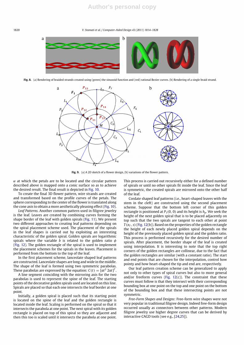
Fig. 9 presents a 2D sketch of such a flower design. We considerconcentric circles C1(M, R1) that contain the flower design, andC3(M, R2) corresponding to the center of the flower. Given thenumber of flower petals n to be used in the flower design, circlesC1 and C3 are divided into n equal segments, whose borders aredefined by lines Li (i = 1, . . . , n). The flower petal correspondingto each segment is represented by a curve Fi (i = 1, . . . , n) thatinterpolates points Pij, where i = 1, . . . , n and j = 1, . . . , k, with kreferring to the number of points used for interpolation. The start
and end points used for interpolation, i.e., P11 and P15, are locatedon curve C3 and are common for adjacent flower petals, whereasthe point corresponding to the tip of each petal, for example P13,represents the position where C1 is tangent to the petal.
To ensure model robustness and efficiency, we require thatadjacent petals not only have common start and end points, butalso have overlapping/intersecting segments. This is accomplishedby considering a circular guide curve C2(M, R2) where R2 = R3 + sand s corresponding essentially to the length of the overlappingpetal curve segment. The points where lines Li, that divide thecircles into segments, intersectwith circle C2 are used as data inputfor the interpolating petal curve.
Relevant parameters for the flower design: the flower centerbead size, which is defined by the radius of the sphere constructedin the middle of the flower, the flower petal length, which isdefined as the length m = R1 − R3, and the number of flowerpetals n.
Suppose the flower design is to be constructed so that it is notflat on a surface, but lies on a cone. The end user specifies an angle
Author's personal copy
1820 V. Stamati et al. / Computer-Aided Design 43 (2011) 1814–1828
a b
Fig. 8. (a) Rendering of braided strands created using (green) the sinusoid function and (red) rational Bezier curves. (b) Rendering of a single braid strand.
Fig. 9. (a) A 2D sketch of a flower design, (b) variations of the flower pattern.
α at which the petals are to be located and the circular patterndescribed above is mapped onto a conic surface so as to achievethe desired result. The final result is depicted in Fig. 10.
To create the final 3D flower pattern, wire strands are createdand transformed based on the profile curves of the petals. Thesphere corresponding to the center of the flower is translated alongthe cone axis to obtain amore aesthetically pleasing effect (Fig. 10).
Leaf Patterns. Another common pattern used in filigree jewelryis the leaf. Leaves are created by combining curves forming theshape border of the leaf with golden spirals (Fig. 11). We presenttwo different approaches to creating leaf patterns depending onthe spiral placement scheme used. The placement of the spiralsin the leaf shapes is carried out by exploiting an interestingcharacteristic of the golden spiral. Golden spirals are logarithmicspirals where the variable b is related to the golden ratio φ(Fig. 12). The golden rectangle of the spiral is used to implementthe placement schemes for the spirals in the leaves. Placement isperformed from the bottom to the top of the leaf.
In the first placement scheme, lanceolate shaped leaf patternsare constructed. Lanceolate shapes are long andwide in themiddle.The shape of the leaf is formed using two symmetric parabolas.These parabolas are expressed by the equation: C(t) = [at2 2at]T .
A line segment coinciding with the mirroring axis for the twoparabolas is used to represent the spine of the leaf. The startingpoints of the decorative golden spirals used are located on this line.Spirals are placed so that each one intersects the leaf border at onepoint.
Initially, a golden spiral is placed such that its starting pointis located on the spine of the leaf and the golden rectangle islocated inside the leaf. Scaling is performed on the spiral so that itintersects the parabola at one point. The next spiral with its goldenrectangle is placed on top of this spiral so they are adjacent andthen this too is scaled until it intersects the parabola at one point.
This process is carried out recursively either for a defined numberof spirals or until no other spirals fit inside the leaf. Since the leafis symmetric, the created spirals are mirrored onto the other halfof the leaf.
Cordate shaped leaf patterns (i.e., heart-shaped leaves with thestem in the cleft) are constructed using the second placementscheme. Suppose that the bottom left corner of this goldenrectangle is positioned at P1(0, 0) and its height is hp. We seek theheight of the next golden spiral that is to be placed adjacently ontop such that the two spirals are tangent to each other at pointT (xT , s) (Fig. 12(b)). Based on the properties of the golden rectanglethe height of each newly placed golden spiral depends on theheight of the previously placed golden spiral and the golden ratio.This process is performed recursively for the desired number ofspirals. After placement, the border shape of the leaf is createdusing interpolation. It is interesting to note that the top rightcorners of the golden rectangles are collinear, due to the fact thatthe golden rectangles are similar (with a constant ratio). The startand end points that are chosen for the interpolation, control howpointy and how heart-shaped the tip and end are, respectively.
Our leaf pattern creation scheme can be generalized to applynot only to other types of spiral curves but also to more generaland/or freeform curves (Fig. 12(c)). The constraint that thesecurves must follow is that they intersect with their correspondingbounding box at one point on the top and one point on the bottomof the bounding box and that these intersecting points are notsymmetric.
Free-Form Shapes and Designs: Free-form wire shapes were notvery popular in traditional filigree design. Indeed free-form designoccurred usually as connectors between other patterns. Modernfiligree jewelry use higher degree curves that can be derived byinteractive CAGD tools (see e.g., [24,25]).

Author's personal copy
V. Stamati et al. / Computer-Aided Design 43 (2011) 1814–1828 1821
a b c d
Fig. 10. (a) The final flower design, (b) initial flower pattern after construction, (c) translated beaded center for a better fit with the petals, (d) alternative design withrounded petals.
a b
Fig. 11. (a) A pattern simulating a lanceolate shaped leaf. (b) A pattern simulating a cordate shaped leaf.
a b c
Fig. 12. (a) A golden rectangle and the corresponding golden spiral. (b) Assembling scaled tangent golden spirals to form a leaf-like pattern. (c) A leaf-like pattern usingfreeform curves.
3.4. Decorative elements
The final aesthetic effect of the designed jewelry is givenby elements that are used for decorative purposes. Solid beadsof different sizes are frequently used to decorate the jewelry.These beads are placed on the model and Boolean union isperformedon themand their respectivemodel component. A planecorresponding to the local surface on which the model componentlies at the point where the bead is imported is used to cut the solidbead to create a flat surface. Jewels and stones can be embeddedin/on the jewelry piece. Finally, decorative borders are used whichare bolder, thicker, decorative strands of wires, usually in the formof braids or intersecting wire strand pairs.
4. Filigree jewelry reconstruction
An overview of the task flow of our filigree jewelry re-engineering and reconstruction tool suite is presented in Fig. 13.
A reverse engineering option (described in Section 4.1) isprovided that allows the user to load a point cloud and extractinformation regarding feature regions and border sets that can beused as a guide during the feature reconstruction and placementprocess (described in Section 4.2).
For experienced users, a straightforward feature-basedcomputer-aided design option is also available (i.e. using directly
the process described in Section 4.2 on an existing jewelry tem-plate). The reverse engineering option can be used stand alone, incases where the detail derived is sufficient to reconstruct the jew-elry piece. In this case the editability of the resulting CAD model islimited.
Traditional reproducing techniques using rubber molds willonly capture a rough approximation of the 3Dmodel by effectivelywrapping an elastic watertight surface around the filigree jewelrypiece. Furthermore, such techniques are not capable of restoringmissing parts or additive editing of the resulting mold or thecorresponding wax replica that will be used for traditionalinvestment casting.
This section makes the following key technical contributions:(i) presents carefully designed practical point cloud analysistools for feature and symmetry detection and (ii) describes aneffective user interface for creating design features and placingthem with respect to each other so as to create editable CADmodels of very fine detail jewelry pieces. This tool suite hasbeen implemented using the Microsoft Visual C++ programmingenvironment and the ACIS R18 solid modeling library provided bySpatial [26].
4.1. Jewelry re-engineering
The issue of re-engineering jewelry, and especially filigreejewelry, presents many difficulties, mainly due to the small size

Author's personal copy
1822 V. Stamati et al. / Computer-Aided Design 43 (2011) 1814–1828
Fig. 13. An overview of our filigree jewelry reconstruction tool suite.
a b c
Fig. 14. (a), (b) The point cloud derived by using a 3D laser scanner on the brooch. (c) Feature component detection and extraction performed on the point cloud.
and fineness of detail. To this end, one needs to capture thefeatures of the original jewelry model and the relationships andconstraints that hold among them.We are still far from developingfully automated reverse engineering systems where there is nohuman intervention. It is more appropriate to design systemswhere the user interactswith the system and provides informationthat can be used to acquire a more accurate and complete CADrepresentation of the object. In our approach we have aimedat achieving some level of automation without sacrificing real-time response and high accuracy. This approach has been adoptedsuccessfully by general purpose reverse engineering systems [27].
A piece of filigree jewelry is usually scanned using a 3D laserscanner producing a point cloud. Due to the generally small size ofjewelry and the delicacy and fineness of their decorative details,scanning techniques can adequately capture only major designfeatures and their relative placement on the object that is beingscanned. Aesthetic detail cannot be captured in a way that isuseful for reconstruction. An example of a 3D point cloud of afiligree brooch, acquired using a handheld Handyscan EXASCANlaser scanner (accuracy 40 µm), is illustrated in Fig. 14. It is clearthat the filigree details of the brooch cannot be inferred from thescanned data. However, we use the point cloud to extract theoverall topology that will guide the identification and placementof the primitives and the overall shape of the jewelry piece.
4.1.1. Point cloud segmentationThere are various methods that can be used for the segmenta-
tion of the initial object, such as [28,29]. A thorough survey of 3Dmesh segmentation methodologies examining their suitability forCADmodels is presented in [30]. To detect feature regions we haveadapted a method developed earlier in [31] for reverse engineer-ing based on discovering features on the point cloud by detectinglocal changes in the morphology of the underlying geometry. Weapplied this method on meshes, where vertex adjacency informa-tion is provided a priori. By detecting rapid variations of the sur-face normal and measuring the concavity intensity we are able toapply a region-growing technique to extract a number of regionsthat represent object features (Fig. 14).
More specifically, the concavity intensity of a vertex vi of amesh, denoted by I(vi), is the distance of vi from the convex hull ofthe mesh. This characteristic is used to detect concave features onthe mesh. Then a region growing is used to detect sets of verticesthat belong to individual features. Such an example is illustrated inFig. 14(c). The feature regions that are detected correspond to thebasic brooch components: four decorative ensembles, the flowercenterpiece and a number of decorative beads.
By segmenting the point cloud into feature regions andboundary sets, we are able to reconstruct the boundary contoursfor each area using curve approximation methods, such as

Author's personal copy
V. Stamati et al. / Computer-Aided Design 43 (2011) 1814–1828 1823
[32]. Reconstructed boundaries are used in conjunction witha symmetry detection technique [33] for adapting and placingdesign elements.
From each detected feature the following data are retrieved:
(a) the size of the area covered by the feature by computing thecorresponding bounding box,
(b) the orientation of the bounding box, based on the principalaxes,
(c) the feature boundary, by reconstructing the boundary contourfrom the border sets extracted during mesh segmentation,
(d) the morphology of the feature area, by deriving an initialsurface representation using approximation and fitting. Tensorproduct surfaces are used to approximate curved areas anddata concerning the curvature of the area is derived, to be usedlater on in the design process for operations such as featurecomponent bending.
4.1.2. Symmetry detectionWe use the principal axes of the point cloud to partition
it into components in which we search for symmetric featureareas. We create a proximity graph that captures local featureplacement information as illustrated in Fig. 15, for each part ofthe object. For each feature region pair, we calculate the geodesicdistances between the centroids of the corresponding regions. Thegraphs are then simplified by reducing the edges that correspondto large geodesic distances to facilitate region matching. This isaccomplished efficiently by establishing an edge between twofeature nodes if and only if the distance of their centroids is lessthan a distance RM that determines the radius of the local structurethat we wish to capture. In Fig. 15 this distance is set to about 1
3 ofthe total width of the brooch.
In addition, small regions that are insignificant are attachedto adjacent major regions, or if there is no adjacent major regionthey are merged to establish a larger region (if the result is stillinsignificant, the corresponding feature region is omitted). Thelarger feature region (that represents the platform of the object) isomitted. Finally, regions that do not belong completely in the partthat we analyze are left out.
In simple cases, where meshes have an almost identicalstructure, matching of the corresponding graphs is trivial. Formore complex cases, meshes exhibit only local structural featuresimilarity. Therefore, by eliminating the edges with large geodesicdistances we match only local neighborhoods in the graph. Theselocal neighborhoods still capture high-level information about thestructure of the features, for example detect pattern similaritiesbetween slightly different models.
The reduced morphology graphs are used to perform a3D alignment of the two sides of the model and establish acorrespondence among feature regions as follows:
• Match the highest degree nodes in each graph and translate saythe second part so that the centroids of their highest degreefeature regions coincide.
• Match the send highest degree nodes and align by rotating andscaling the second part so that the centroids of their secondhighest degree feature regions coincide.
• Perform a 3D alignment of the two components by rotating thesecond part around the axis defined by the centroids of the twoaligned feature regions so that the Hausdorff distance of thepoint cloud of the second part from the point cloud of the firstpart is minimized.
The remaining regions are paired according to their degreeand the distance between them. Furthermore, we also take intoconsideration the area covered by each region by favoring the
matching of regions that have similar areas. We have used thefollowing heuristic similarity measure for matching:
sij = ∥ci − cj∥maxkϵ{i,j}
ak
minlϵ{i,j}
al
maxmϵ{i,j}
dm
minnϵ{i,j}
dn(2)
where ci and cj are the centroids of regions i and j, ai and aj are thecorresponding areas and di and dj are the degrees of the nodes inthe reduced morphology graphs.
For the example shown in Fig. 14(c), feature detection derivesclusters corresponding to spherical bead elements in the brooch.Using our symmetry detectionmethod, these beads arematched inpairs and constructed to fit the respective feature areas, thereforeautomating significantly the process of constructing and placingthe beads on the brooch. Furthermore, the detected decorativeensemble components provide data that is used for placementof the ensembles during reconstruction, i.e., ensemble orientationand exact location in reference to the base component. Additionalapproximate measures are acquired from the detected featuresin reference to component size and bending angles by exploitingthe oriented bounding box of each feature component data pointset. By constructing and placing one of the ensembles and usingtransformations to modify and place the remaining, we ensurerobustness and fairness in themodel. Also, point sets are extractedthat correspond to feature region boundaries fromwhich free-formcontours are reconstructed to approximate the border, providingguide contours for aligning and fitting the design componentelements. Finally, the base component of the brooch is an area onwhich surface approximation can be performed to derive a basicshape to be used in the feature-based design process.
The user interface for reverse engineering in ReJCAD isdisplayed in Fig. 16. The user imports the point cloud that she/hewants to process and performs feature detection to produce aninitial list of all the feature regions and borders. The user canprocess each feature region detected and either merge it withothers or split it into more components. Symmetry detection iscarried out to produce a suggested list of symmetries which theuser can either confirm or reject. Symmetries are suggested to theend user in pairs of features, while an option is always provided tothe user to add his/her own symmetries between pairs of features.
4.2. Feature reconstruction and placement
The feature-based design process is carried out for each featurearea that is detected and extracted from the reverse engineeringphase or for each feature component that the user plans on creatingbased on her/his design concept.
Initially the user creates a new feature by picking a pat-tern/design and defining the parameter values for the correspond-ing attributes. If re-engineering has been performed prior to thedesign process, then the user can choose a feature region fromthe feature region list as a guide for initial parameter values andplacement. Intra-feature constraints of designs and patterns areenforced during feature definition so as tomake the correspondingfeature rigid. After construction the feature is uploaded into a fea-ture list that contains all the feature components (every instance ofa feature) that are part of the final jewelrymodel. A feature compo-nent is redesigned by editing its parameters, reconstructing it andupdating the feature list. The user can also create profile curvesby curve approximation on border point sets obtained through re-verse engineering. These profile curves are used either as guidesfor placement of a feature or for bending other components alongthese curves. The user has the ability to transform the componentby translation, rotation, scaling, or bending.
After each feature is constructed it is considered as a rigid body.Feature placement is realized through (i) defining inter-feature

Author's personal copy
1824 V. Stamati et al. / Computer-Aided Design 43 (2011) 1814–1828
a b
Fig. 15. (a) The originalmodel divided into two components, according to themajor andminor principal axes. (b) The correspondingmorphology graphs for each component.
Fig. 16. A snapshot of the ReJCAD user interface.
constraints that determine the relative feature placement (with re-spect to each other) and (ii) fixing feature geometry. Constraintsare derived and enforced on the reconstructed jewelry represen-tation to maintain model robustness (manufacturability), confor-mity to filigree craftsmanship (e.g. concentric or aligned patterns)and to support editability through constraints. Constraints relatedto symmetry are derived through re-engineering and aim at en-forcing symmetry,whereas other inter-feature constraints are userdefined. The inter-feature constraints that are supported in ReJCADmainly refer to component size, bending and placement. Specifi-cally, size constraints are set either as equalities or symbolic re-lations. This also holds for bending angles of feature components.Placement constraints refer to coincidence, tangency and distancecharacteristics. More specifically we support the following cate-gories of inter-feature constraints: Determining distances, angles,
fixing of geometric elements, symbolic relations of angles, dis-tances and other geometric characteristics such as radius, area,and volume (symmetry is enforced through relations), ‘‘on’’ con-straints, tangency (supported only for a limited repertoire of ge-ometric primitives), and inequalities (that should be used withcaution, since they can be enforced only during the second stepof nonlinear optimization).
We use a hybrid geometric constraint solving system. Firstbuilding on theprinciples of [34–36]wedetectminimal concurrentnon-linear systems and eliminate symbolic relations. Then weemploy interior point optimization to solve each linear systemof geometric constraints [37]. Interior point optimization is afast local optimization technique that can be combined withoverconstraining to find efficiently unique solutions for theminimal system of geometric constraints. Root multiplicity is

Author's personal copy
V. Stamati et al. / Computer-Aided Design 43 (2011) 1814–1828 1825
a b
Fig. 17. (a) Awire outlined peacock pattern as a brooch base component. (b) Broochbase component featuring nested teardrop patterns.
enabled by combining the subsystems to derive a solution forthe entire system of geometric constraints using the algorithmsdescribed in [34].
After the end user is done placing and editing the newcomponent, a test can be performed on the feature to determineif the final placement is satisfactory for a Boolean union to beperformed to integrate the feature into the final model. The actualunion can be performed at a later phase, when the user hasfinished with the entire model and its re-design. The final modelis checked for robustness and plausible problems that cannot behandled automatically are reported to the user for editing. Morespecifically disjoint parts are reported to the user, non-manifoldedges and faces are corrected automatically, almost non-manifoldfaces and edges are reported to the user, dangling edges and facesare automatically eliminated and holes are automatically covered.The robust model is exported as an STL file that can be submitteddirectly for reproduction.
5. ReJCAD evaluation
In this section we provide a case study of reconstructing afiligree brooch, present a usability study that has been performedto evaluate our application and discuss the robustness andmanufacturability of the reconstructed CAD models.
5.1. A case study
We present an example of designing and creating a filigreebrooch similar to the one illustrated in Fig. 1. This piece ofjewelry is made up of essentially two levels of components, thebase or main component and the decorative and complementaryelements/subcomponents placed on top.
Initially, the base component of the brooch is created. From thereverse engineering processwe cannot obtain sufficient data aboutthe patterns used for this component, however the general shape,morphology and size of the area are derived. This componentis a complex pattern made up of pointy teardrops placed in apeacock pattern. The peacock design covers an angle of 360° andconsists of 14 pointy teardrop segments. Three circle guide curvesare defined to create three different sizes of teardrops (Fig. 17). Asimple wire strand type is chosen to create the pattern outline. Theorigin/center O of the brooch is placed at the center of the peacock.
Next, the design to be featured in each segment is chosen.The same design pattern is chosen for each segment, the nestedteardrop design. The user specifies style and thickness of the wirestrands and the number of strands (Fig. 17). The base componentis decorated with solid beads and a decorative braided border. Thedecorative border is placed by sampling points on the outline of thebase component or using the shape boundary reconstructed fromre-engineering, performing curve fitting to derive the profile curveand then bending a straight braided complex wire of appropriatelength to follow this profile curve (Fig. 19(a)). In this case study,the border contour on which the decorative braid (Fig. 20) is fittedon is created using a segment of the boundary contour of eachpointy teardrop and connecting these segments with quadraticrational Bezier curves with G1 continuity. A parameter k is definedwhich expresses the percentage of the boundary contour of thepointy teardrop that is used as part of the braid contour. A largerk means that a larger segment of the available pointy teardropboundary is used as part of the braid profile contour; therefore thebraid covers more of the surface of the pointy teardrop. Quadraticrational Bezier curves are used to connect adjacent curve segments.Bymodifying the weight of themiddle control point, we adjust thedepth of the braid contour, which aesthetically affects how closelythe braid contour follows the base component.
We create additional model components that will be integratedinto the base component to improve its aesthetics. The basic shapethat is chosen is the pointy teardrop that is combined into 3-pieceensembles. The user-designer specifies the size and the locationof the subcomponent in reference to the base component. Thesubcomponents are placed parallel on top of the base componentwith the tips of the 3-piece subcomponents coinciding with thepositions specified by the user. Bending is performed on each3-piece ensemble around the bending axis (Fig. 18) and towardthe bending direction specified (concave or convex result). Thebending angle is specified by the end-user or is extracted from re-engineering based on the curvature of the corresponding featureregion. After bending, each component is translated so that eachend of the bent component intersects with the base component.
To make the 3-piece peacock ensembles placed on the ends ofthe brooch more robust from a manufacturing point of view, andaesthetically pleasing, we place solid beads at the tips. The broochis decorated with a flower pattern placed at its center (Fig. 19). Thecenter of the flower is also used as the decorative solid bead end ofthe middle peacock ensembles.
The final step in the brooch reconstruction process is bendingthe brooch model in two directions as shown in Fig. 19. Bendingis performed symmetrically along each axis. In general, duringfeature reconstruction and placement, several constraints areimposed on themodel of the filigree brooch that enforce symmetryand relative positioning of features (see Figs. 19 and 20).
Custom design and redesign is realized by selecting featurecomponents and modifying their parameter values. For example,the filigree brooch created above can be modified to achieve theresult shown in Fig. 21. The decorative flower center has beenremoved and the two symmetric peacock ensembles on the ends
Bending direction
Bending axis
a b c
Fig. 18. (a), (b) A front and side view of the brooch decorated with peacock-like ensembles. (c) The 3-piece peacock ensemble.

Author's personal copy
1826 V. Stamati et al. / Computer-Aided Design 43 (2011) 1814–1828
Bending
axis A1
Bending
axis A2
a b
c
Fig. 19. (a) A 3D model of a filigree brooch prior to bending, (b) side views of the model before and after bending in one direction and (c) The 3D CAD model of the broochafter bending is performed in two directions.
Bead B Bead A
Bead
Decorative
Braid Border
Peacock Ensemble E2
Peacock Ensemble E1
Peacock Ensemble E3
Peacock Ensemble E4
Fig. 20. Elements of the brooch on which constraints are enforced.
Fig. 21. A modified version of the filigree brooch.
of the brooch have been translated to the brooch center, such thattheir tips touch. Also all the peacock ensembles are slightly scaledup, to a pointwhere the tips of the top andbottomensembles touchthe decorative beads of the base component.
5.2. Usability evaluation
We have evaluated our application by conducting a trainingprocess. Twelve experienced CAD users (three engineers with ex-perience on Rhino, four graduate students, two jewelry designersand three postdocs all not involved in the project research and de-velopment) underwent a training session on how to use the appli-cation, created a filigree jewelry model under the guidance of thedevelopers and then were asked to repeat the procedure by them-selves by creating a simplified filigree brooch. Following this, they
were asked to fill in a questionnaire evaluating the application bygrading specific aspects of it on a scale of 0 (weak) to 7 (strong). Thequestions regarding the application were questions that evaluatedtwo of the major principles of usability: Learnability (Predictabil-ity, Familiarity, Generalizability, Consistency) and Robustness (Ob-servability, Recoverability, Task Conformance) and the threemajorparameters of usability: Satisfaction, Efficiency and Effectiveness.
The results derived an overall average of: 5.2 out of 7 forefficiency, 5.8 out of 7 for effectiveness and 4.4 out of 7 forsubjective satisfaction. The evaluation revealed that users wereable to create and redesign a 3D CADmodel of filigree jewelry withsatisfactory precision. The general notion among the userswas thatthe tools provided by the application were sufficient for the taskat hand and a precise model can be constructed for reproduction,however an advanced level of knowledge and experience in CADsystems is required to be able to use the application effectively andefficiently.
5.3. Robustness and manufacturability
The CAD model of ReJCAD is exported in STL format and isrobust and ready for manufacturing. Robustness is ensured byperforming a number of validity tests on the resulting STL modelthat results in removing dangling faces, filling holes and correctingvarious inconsistencies. Important for the manufacturability isthe concept of feature element overlapping which guaranteesstability and direct casting manufacturability. To this end, besidesthe per feature wire thickness parameter we provide a globalwire thickness parameter that globally alters wire diameterby ±10% in all features. When decreasing this parameter theobject becomes sharper and when increasing this parameterthe object becomes more coherent. Subsequently, a numberof manufacturing methods can be used to produce jewelry orornamental pieces.
For reconstructing jewelry pieces of high quality from a robustSTL description, direct investment casting of precious metals isthe process that yields fine jewelry pieces: First we use rapidprototyping with high precision machines (with accuracy in thearea of 10 to 70 µm voxels) to produce a high quality resin(or other material) prototype by using layered manufacturingusually by high resolution photopolymerism technology perlayer (stereolithography). Then for direct investment casting, aninvestment is created – that is a negativemold of the jewelry pieceusually made of gypsum – from the resin that is subsequentlyused for precious metal casting. Note that the resin is suchthat it vanished completely without leaving residue and without

Author's personal copy
V. Stamati et al. / Computer-Aided Design 43 (2011) 1814–1828 1827
a b
Fig. 22. (a) An initial synthetic prototype manufactured by a 3D printer and (b) the corresponding unfinished reconstructed jewelry piece after being processed withstrengthening infiltration and metal coating.
interacting with the investment usually at moderate burn outtemperatures. We have checked the feasibility of this process on aPerfactory Mini Multi Lens by EnvisionTec with SXGA+ resolution,75mm lens, and ERM (Enhanced ResolutionModule) XY voxel size21 µm and dynamic voxel thickness 15 µm (depending on thematerial) with the PIC100 resin for direct investment casting (seealso [38]).
For an overview of such technologies the reader is referred to[39]. Several state of the art machines supporting these productionprocesses can be found in [40,38].
For creating more inexpensive faux bijoux pieces, currenttechniques use ceramic or other highly resistant syntheticmaterialfor 3D printing and then a nickel, chrome of copper based mixtureof metal coating is applied. The result is solid and wearable and itmay become colorful by using color agents in the coating materialor subsequent silver or gold plating to improve appearance andwearability. Metal coating results in deterioration of resolution butit is muchmore affordable for producing a small number of pieces.
A prototype of the CADmodel is shown in Fig. 22(a), which wasproduced using a Z450 (Zcorp R⃝ 3D Printer) andmade out of zp130plaster powder containing crystalline silica and vinyl polymer.Fig. 22(b) shows a final reconstructed jewelry piece after beingprocessed with medium strength infiltrant and metal coated. Thesize of both pieces is approximately 2 in by 1.2 in which is slightlylarger than the original brooch size (0.9 in. by 1.1 in.). Note thatsome detail has vanished as a result of the metal coating process.
6. Conclusions
Filigree jewelry requires highly detailed and complex crafts-manship. Until now, there has been no technique to reconstructand manufacture such pieces through CAD/CAM models. ReJCADprovides the means for performing filigree jewelry reconstructionthrough an effective partially automated process that takes a pointcloud of the object as input and extracts boundary curves and otherinformation referring to placement and symmetry. This data isthen used to guide reconstruction supported by an extensive fil-igree feature library. We have proposed schemes for representingand modeling design features that are commonly used in filigreecraftsmanship. Overall, we have reported on the development of aversatile and robust system for reconstructing filigree jewelry andwe have demonstrated its usefulness through an example case, ausability evaluation and examples of actually manufactured jew-elry.
The final result has been reviewed by jewelry artists and localcraftsmen. They have all found the result of very fine detailespecially the part of engraving which usually suffers throughreconstruction. The robust final outcome can be manufacturedthrough accurate resin prototyping after making a highly detailedgypsum investment. Some experimentation should be performed
based on the complexity of the investment and the metal mixtureused for achieving best results for castings using precious metals.
The overall CADmodel or single features can be easily importedand used by other jewelry CAD software such as Rhino or Matrixby exporting the models through ReJCAD to SAT, 3DM or otherappropriate file format for adding precious stones or performingother artistic alterations and corrections in the expense of losingpart of the constraint-based editing capabilities.
References
[1] Malagoli MG. CAD/CAM technology — transforming the Goldsmith’s work-shop. Gold Technology 2002;34:31–5.
[2] Molinari LC, Megazzini MC. The role of CAD/CAM in the modern jewellerybusiness. Gold Technology 1998;23:3–7.
[3] Hoffmann CM, Joan-Arinyo R. On user-defined features. Computer AidedDesign 1998;30(5):321–32.
[4] Bronsvoort W, Bidarra R, van der Meiden H, Tutenel T. The increasing role ofsemantics in object modeling. Computer Aided Design and Applications 2010;7(3):431–40.
[5] BohmW. Design opportunities through production technology. Gold Technol-ogy 1998;23:8–11.
[6] Andrews C. Ancient egyptian jewellery. British Museum Publications; 1990.[7] Untracht O. Jewelry of India. Thames and Hudson; 1997.[8] Sequin C. CAD tools for aesthetic engineering. Computer-Aided Design 2005;
37:737–50.[9] Sequin C. Computer-aided design and realization of geometrical sculptures.
Computer-Aided Designs and Applications 2007;4(5):671–81.[10] Furuta Y, Mitani J, Igarashi T, Fukui Y. Kinetic art design system comprising
rigid body simulation. Computer Aided Design and Applications 2010;7(4):533–46.
[11] Liu Y, Zhang D, Yuen M. A survey on CAD methods in 3D garment design.Computers in Industry 2010;61:576–93.
[12] Jewellery CAD/CAM Limited. JewelCAD. Available from: http://www.jcadcam.com.
[13] Robert McNeel & Associates. Rhinoceros. NURBS modleing for Windows.Available from: http://www.rhino3d.com/jewelry.htm.
[14] Delcam. ArtCAM JewelSmith. Available from: http://www.artcamjewelsmith.com/.
[15] Gemvision. Matrix 3D jewelry design software. Available from: http://www.gemvision.com/html/products/matrix/matrix.html.
[16] 3Design. 3Design CAD. Available from: http://www.3design.com/.[17] Stamati V, Fudos I. A parametric feature-based CAD system for reproducing
traditional pierced jewellery. Computer Aided Design 2005;3(74):431.[18] Stamati V, Fudos I. Building editable Brep models from unorganized point
clouds. Department of Computer Science, University of Ioannina Greece; 2010.TR.2010-04.
[19] Gulati V, Singh H, Tandon P. A parametric voxel based unified modeler forcreating carved jewerly. Computer Aided Design and Applications 2008;5(6):811–21.
[20] Gulati V, Tandon P, Singh H. A jewelry modeler for the fret-worked bangles.International Journal of Computer Applications 2010;2(2):76–80.
[21] Kai CC, Gay R. CAD/CAM/CAE for ring design and manufacture. Computer-Aided Engineering 1991;(February):13–24.
[22] Stamati V, Antonopoulos G, Azariadis Ph, Fudos I. ReJCAD: a feature-based CADsystem for reconstructing traditional filigree jewelry. Greece: Department ofComputer Science, University of Ioannina; 2011. TR-2011-4.
[23] Bates L, Wyvill B, Yao C. The visualization of knots and braids. The Journal ofVisualization and Computer Animation 1992;3(2):91–104.
[24] Llamas I, Kim B, Gargus J, Rossignac J, Shaw C. Twister: a space-warp operatorfor the two-handed editing of 3D shapes. In: ACMSIGGRAPH2003. ACM; 2003.

Author's personal copy
1828 V. Stamati et al. / Computer-Aided Design 43 (2011) 1814–1828
[25] Rossignac J, Schaefer S. JSplines. Journal of Computer-Aided Design 2008;40(10–11):1024–32.
[26] Spatial. ACIS 3D modeling. Available from: http://www.spatial.com.[27] Fisher RB. Applying knowledge to reverse engineering problems. Computer-
Aided Design 2004;36:501–10.[28] Varady T, Facello M, Terek Z. Automatic extraction of surface struc-
tures in digital shape reconstruction. Computer Aided Design 2007;39:379–388.
[29] Stamati V. Reconstructing feature-based CAD models based on point cloudmorphology. Ioannina: Dept. of Computer Science, University of Ioannina;2008.
[30] Agathos A, Pratikakis I, Perantonis S, Sapidis N, Azariadis P. 3D meshsegmentation methodologies for CAD applications. Computer-Aided Designand Applications 2007;4(6):827–42.
[31] Stamati V, Fudos I. A feature-based approach to re-engineering objects offreeform design by exploiting point cloud morphology. In: SPM 2007: ACMsymposium on solid and physical modeling. 2007.
[32] Stamati V, Fudos I. On reconstructing 3D feature boundaries. Computer AidedDesign and Applications 2008;5(1–4):316–24.
[33] Athanasiadis T, Fudos I, Nikou C, Stamati V. Feature-based 3Dmorphing basedon geometrically constrained sphere mapping optimization. In: SAC 2010.2010.
[34] Fudos I, Hoffmann CM. A graph-constructive approach to solving systems ofgeometric constraints. ACM Transactions on Graphics 1997;16(2):179–216.
[35] Hoffmann CM, Joan-Arinyo R. Symbolic constraints in constructive geometricconstraint solving. Journal of Symbolic Computation 1997;23:287–99.
[36] de Regt R, van der Meiden H, Bronsvoort W. A workbench for geometricconstraint solving. Computer Aided Design and Applications 2008;5(1–4):471–82.
[37] Wachter A, Biegler LT. On the implementation of an interior-point filterline-search algorithm for large-scale nonlinear programming. MathematicalProgramming 2006;106(1):25–57.
[38] EnvisionTec. Computer aided modeling devices. Available from: http://www.envisiontec.de.
[39] Wannarumon S, Bohez ELJ. Rapid prototyping and tooling technology injewelry CAD. Computer Aided Design and Applications 2004;1(1–4):569–76.
[40] LB Jewelry Design, Inc. Jewelry design. Available from: http://www.lbjewelrydesign.com/.