this information manual describes the operation, product
TRANSCRIPT
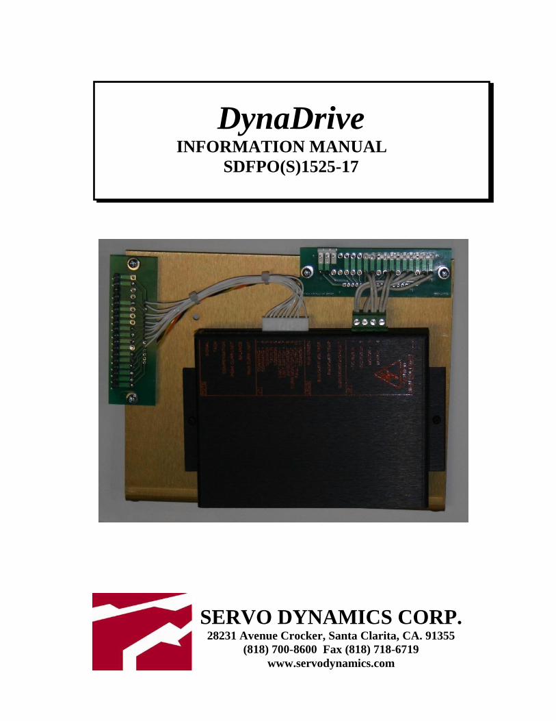
DynaDrive
INFORMATION MANUAL
SDFPO(S)1525-17
SERVO DYNAMICS CORP. 28231 Avenue Crocker, Santa Clarita, CA. 91355
(818) 700-8600 Fax (818) 718-6719
www.servodynamics.com

- 1 -
INDEX Page INTRODUCTION 2 ELECTRICAL CAUTIONS 2 SPECIFICATIONS 3 WIRING DIAGRAM 4 OPERATIONAL MODES 5 TORQUE MODE - FACTORY POTENTIOMETER SETTINGS 5 TORQUE MODE - SETUP 6
MATCHING THE DYNADRIVE TO THE MOTOR 7
VELOCITY MODE – POTENTIOMETER SETTINGS 8 VELOCITY MODE - SETUP 9 CONNECTOR INFORMATION 10 ADJUSTMENTS 11 TEST POINT INFORMATION 11 TROUBLESHOOTING 12 MOUNTING DIMENSIONS 14
SDFPO(S)1525-17, Revised 1/1/11

- 2 -
INTRODUCTION This information manual provides the product specifications, wiring diagram, operational modes (torque and velocity) and troubleshooting procedures for the brush DynaDrive SDFPO(S)1525-17. The DynaDrive SDFPO(S)1525-17 supplies 15 amps continuous current and 25 amps peak current at 164 VDC for a total of 2460 watts of continuous power. The DynaDrive is a current source type PWM amplifier. The DynaDrive is a power duplicator of the command signal. A battery, a motion controller, or a signal generator can be the source of the command signal input.
ELECTRICAL CAUTIONS Make sure that all voltages and tests are made with battery powered or electrically isolated instruments.
- 3 -
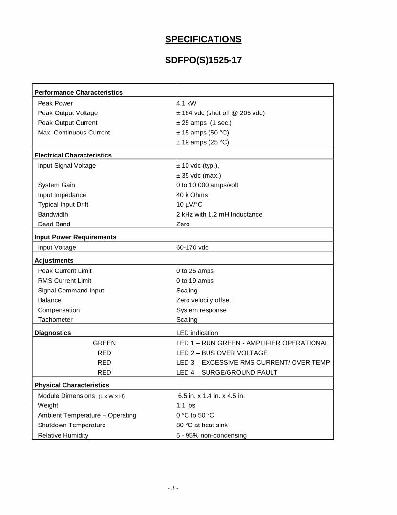
SPECIFICATIONS
SDFPO(S)1525-17
Performance Characteristics
Peak Power 4.1 kW
Peak Output Voltage ± 164 vdc (shut off @ 205 vdc)
Peak Output Current ± 25 amps (1 sec.)
Max. Continuous Current ± 15 amps (50 °C),
± 19 amps (25 °C)
Electrical Characteristics
Input Signal Voltage ± 10 vdc (typ.),
± 35 vdc (max.)
System Gain 0 to 10,000 amps/volt
Input Impedance 40 k Ohms
Typical Input Drift 10 µV/°C
Bandwidth 2 kHz with 1.2 mH Inductance
Dead Band Zero
Input Power Requirements
Input Voltage 60-170 vdc
Adjustments
Peak Current Limit 0 to 25 amps
RMS Current Limit 0 to 19 amps
Signal Command Input Scaling
Balance Zero velocity offset
Compensation System response
Tachometer Scaling
Diagnostics LED indication
GREEN LED 1 – RUN GREEN - AMPLIFIER OPERATIONAL
RED LED 2 – BUS OVER VOLTAGE
RED LED 3 – EXCESSIVE RMS CURRENT/ OVER TEMP
RED LED 4 – SURGE/GROUND FAULT
Physical Characteristics
Module Dimensions (L x W x H) 6.5 in. x 1.4 in. x 4.5 in.
Weight 1.1 lbs
Ambient Temperature – Operating 0 °C to 50 °C
Shutdown Temperature 80 °C at heat sink
Relative Humidity 5 - 95% non-condensing

- 4 -
WIRING DIAGRAM DynaDrive SDFPO(S)1525-17
J5(S)
J4(S)
J4
J3
J2(S)
J1(S)
Test points 1-7
Pots
Sig.
Tach.
Comp.
CL.
Bal
RMS

- 5 -
OPERATIONAL MODES The DynaDrive can operate in a Torque or Velocity mode. In the Torque mode, the DynaDrive only closes the torque loop. The velocity loop is closed in the motion controller. In the Velocity mode, the DynaDrive itself closes both the torque and velocity loop.
TORQUE MODE - FACTORY POTENTIOMETER SETTINGS Unless otherwise specified by the customer, the DynaDrive SDFPO(S)1525-17 is shipped in the torque mode by installing the torque mode jumper at J3 and presetting the potentiometers for the torque mode. The factory potentiometer settings for the torque mode are as follows: (See ADJUSTMENTS section for a more complete description of the potentiometer functions). All resistance measurements must be made with power off and J1 disconnected.
Table 1
Potentiometer Description
Potentiometer Setting
Potentiometer Test Point
N/A N/A TP1 – COMMON
SIGNAL 4.8 k Ohms TP2 – SIGNAL
TACH Full CCW TP3 – TACH
COMPENSATION Full CW TP4 – COMPENSATION
PEAK CURR LIMIT Full CW, 2.2 k Ohms (25 Amps)
TP5 – PEAK CURR LIMIT
BALANCE No Preset None
RMS 11.6 k Ohms (15 Amps) TP7 – RMS
Note: All Measurements are with respect to TP1 (Common) with J1 removed.

- 6 -
TORQUE MODE - SETUP The factory preset potentiometer settings are adjusted for the torque mode operation. To set up and run the DynaDrive SDFPO(S)1525-17 in the torque mode, perform the following:
1. Turn power off. 2. Remove J1. 3. Check all wiring connections. Verify that J3 jumper is installed. 4. Set the RMS, PEAK CURRENT LIMIT and SIGNAL pots to match the motor
as indicated in Table 2. For preliminary testing under no load, use the factory preset pot settings.
5. Check that the TACHOMETER pot is full counterclockwise (CCW). 6. Check that the COMPENSATION pot is full clockwise (CW). 7. Replace J1. 8. Inhibit the DynaDrive by pulling pin 8 of J1 to common. 9. Turn power on. 10. Insure that the voltage at COMMAND + and COMMAND – is zero. 11. Enable the Dynadrive by removing the inhibit of step 8. 12. The green LED should be the only LED on. No other LEDs should be on at
this point. If any other situation exists, check the TROUBLESHOOTING section of this manual.
13. Adjust the BALANCE pot to give zero volts at CURRENT MONITOR OUT, J1 pin 9.
14. Apply a voltage (0 to +/- 10 Vdc) at COMMAND + and COMMAND -. The motor shaft should turn CW when COMMAND + is positive and should turn CCW when COMMAND + is negative. At low COMMAND voltage, holding the shaft can stall the motor. At higher COMMAND voltage, the torque is much greater and it should be difficult to stall the motor.

- 7 -
MATCHING the DynaDrive to the M0T0R
The factory preset potentiometer settings of the DynaDrive SDFPO(S)1525-17 may need to be adjusted to match the continuous current rating of your motor. To accomplish this, find the continuous current rating of the motor to be used and adjust the RMS, PEAK CURR LIMIT and SIGNAL pot per Table 2 below. If the continuous current rating is between the values shown in the table, you may set to the lower value or use linear interpolation for each pot value. The signal pot settings are based on +/- 10 vdc input command signal. Remember that all resistance measurements must be made with power off and J1 disconnected.
Table 2
Continuous Current Rating of
Motor (Amps)
RMS Pot Setting
TP7 K Ohms (Amps)
PEAK CURRENT LIMIT Pot Setting
TP5 K Ohms (Amps)
SIGNAL Pot Setting
TP2 K Ohms
3 4.0 (3 Amps) 0.7 (9 Amps) 2.0
6 6.6 (6 Amps) 1.6 (18 Amps) 3.8
9 8.9 (9 Amps) 2.2 (25 Amps) 4.8
12 10.5 (12 Amps) 2.2 (25 Amps) 4.8
15 11.6 (15 Amps) 2.2 (25 Amps) 4.8
Note: All Measurements are with respect to TP1 (Common) with J1 removed.
- 8 -
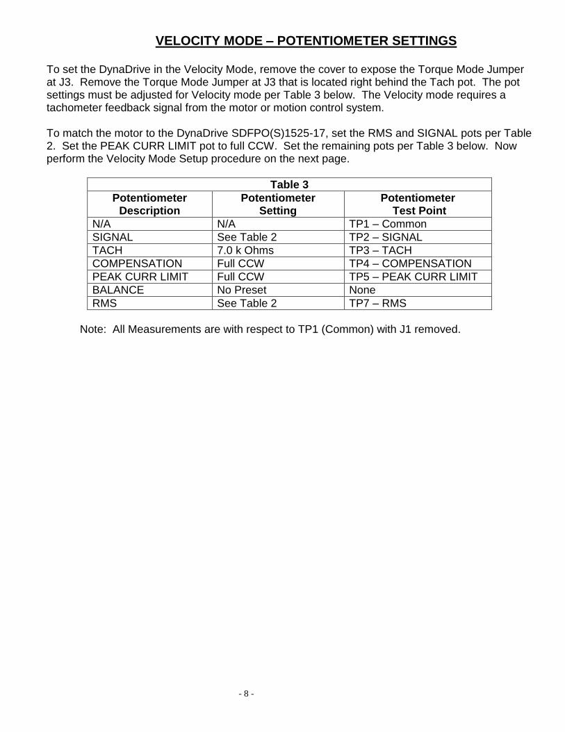
VELOCITY MODE – POTENTIOMETER SETTINGS
To set the DynaDrive in the Velocity Mode, remove the cover to expose the Torque Mode Jumper at J3. Remove the Torque Mode Jumper at J3 that is located right behind the Tach pot. The pot settings must be adjusted for Velocity mode per Table 3 below. The Velocity mode requires a tachometer feedback signal from the motor or motion control system. To match the motor to the DynaDrive SDFPO(S)1525-17, set the RMS and SIGNAL pots per Table 2. Set the PEAK CURR LIMIT pot to full CCW. Set the remaining pots per Table 3 below. Now perform the Velocity Mode Setup procedure on the next page.
Table 3
Potentiometer Description
Potentiometer Setting
Potentiometer Test Point
N/A N/A TP1 – Common
SIGNAL See Table 2 TP2 – SIGNAL
TACH 7.0 k Ohms TP3 – TACH
COMPENSATION Full CCW TP4 – COMPENSATION
PEAK CURR LIMIT Full CCW TP5 – PEAK CURR LIMIT
BALANCE No Preset None
RMS See Table 2 TP7 – RMS
Note: All Measurements are with respect to TP1 (Common) with J1 removed.

- 9 -
VELOCITY MODE - SETUP To set up and run the DynaDrive SDFPO(S)1525-17 in the Velocity mode, perform the following:
1. Turn power off. 2. Remove J1. 3. Check all wiring connections. Verify that J3 jumper is removed. 4. Check that the pots are set per Table 3. 5. Inhibit the DynaDrive by pulling pin 8 of J1 to common. 6. Replace J1. 7. Turn power on. 8. Insure that the voltage at COMMAND + and COMMAND – is zero.
9. Enable the DynaDrive by removing the inhibit of step 5. 10. The green LED should be the only LED on. No other LEDs should be on
at this point. If any other situation exists, check the TROUBLESHOOTING section of this manual.
11. Slowly turn the PEAK CURR LIMIT pot CW. If the motor runs away, turn the power off, reverse the velocity feedback leads and repeat above. If the motor does not run away, set the PEAK CURR LIMIT pot to the value given in Table 2.
12. Turn the COMPENSATION pot CW until the motor starts buzzing. Now turn the pot CCW until the motor stops buzzing and then turn another 1 ½ turns CCW.
13. The motor shaft should not be rotating at this point. If it is slowly rotating, adjust the BALANCE pot until rotation is stopped.
14. With zero voltage at COMMAND + and COMMAND –, the motor shaft should be stiff and difficult to turn. A low voltage at COMMAND + will cause the motor to turn at a slow speed with high torque and the motor should be difficult to stall. The motor speed should be proportional to the COMMAND voltage.
- 10 -
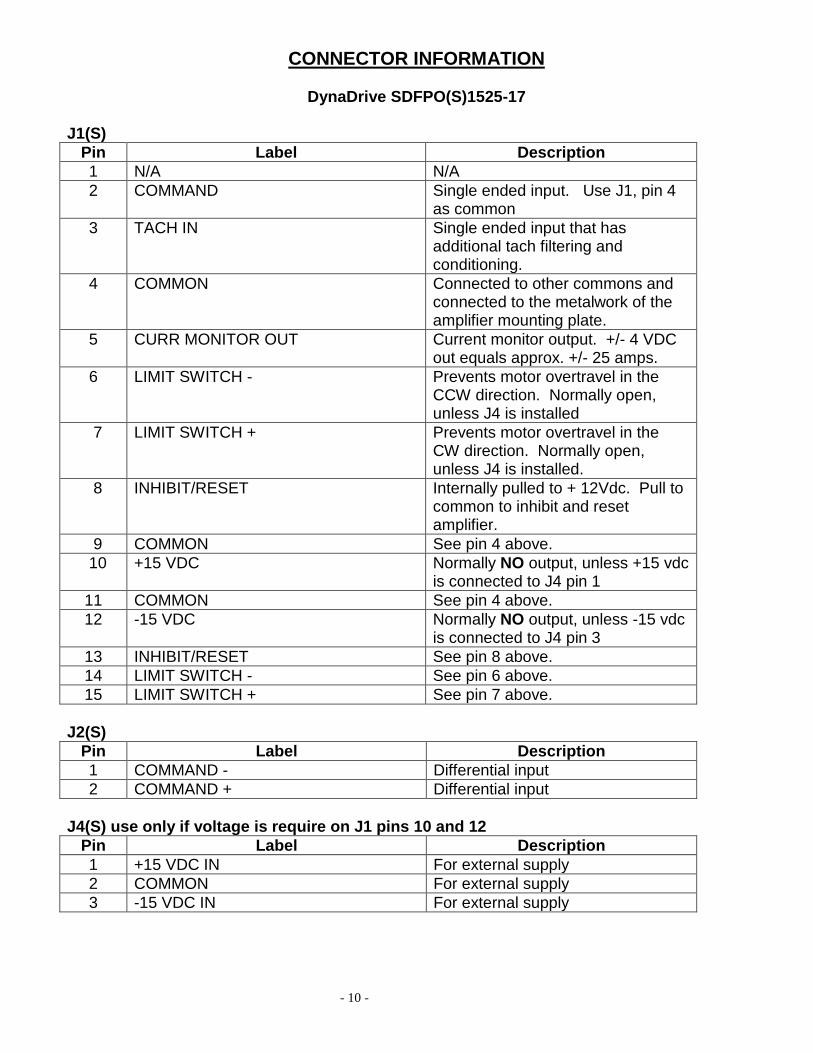
CONNECTOR INFORMATION
DynaDrive SDFPO(S)1525-17
J1(S)
Pin Label Description
1 N/A N/A
2 COMMAND Single ended input. Use J1, pin 4 as common
3 TACH IN Single ended input that has additional tach filtering and conditioning.
4 COMMON Connected to other commons and connected to the metalwork of the amplifier mounting plate.
5 CURR MONITOR OUT Current monitor output. +/- 4 VDC out equals approx. +/- 25 amps.
6 LIMIT SWITCH - Prevents motor overtravel in the CCW direction. Normally open, unless J4 is installed
7 LIMIT SWITCH + Prevents motor overtravel in the CW direction. Normally open, unless J4 is installed.
8 INHIBIT/RESET Internally pulled to + 12Vdc. Pull to common to inhibit and reset amplifier.
9 COMMON See pin 4 above.
10 +15 VDC Normally NO output, unless +15 vdc is connected to J4 pin 1
11 COMMON See pin 4 above.
12 -15 VDC Normally NO output, unless -15 vdc is connected to J4 pin 3
13 INHIBIT/RESET See pin 8 above.
14 LIMIT SWITCH - See pin 6 above.
15 LIMIT SWITCH + See pin 7 above.
J2(S)
Pin Label Description
1 COMMAND - Differential input
2 COMMAND + Differential input
J4(S) use only if voltage is require on J1 pins 10 and 12
Pin Label Description
1 +15 VDC IN For external supply
2 COMMON For external supply
3 -15 VDC IN For external supply

- 11 -
J5(S)
Pin Label Description
1&2 + DC BUS IN + Bus power input, 60 to 170 VDC
4&5 - DC BUS IN - Bus power input, power return
7&8 MOTOR - Output power to motor
10&11 MOTOR + Output power to motor
ADJUSTMENTS
The following is a description of the function of each pot. The pot settings can be measured at test points TP1 thru TP7.
SIGNAL The signal potentiometer is used for scaling the command signal. Turning the
potentiometer CW increases the amount of command signal to the front end of the amplifier.
TACH The tachometer potentiometer is used for scaling the various tachometer voltage gradients. This input has to be used because of special signal conditioning. Turning the pot CW increases the amount of tach-feedback into the amplifier.
COMPENSATION The Compensation potentiometer is used to increase or decrease the response (bandwidth) of the amplifier. Turning the potentiometer CW increases the response of the amplifier.
PEAK CURR LIMIT The peak current limit potentiometer is used to increase or decrease the peak output current of the amplifier. Turning the potentiometer CW increases the output current of the amplifier from zero amps to maximum peak amps.
BALANCE The balance potentiometer is used to stop motor rotation when no input signal exists. The function of this pot is such that for zero input volts the output current should be at zero amps.
RMS POT The RMS potentiometer is for changing the level of the RMS current. The amplifier is capable of providing maximum RMS current when fully CW. The minimum current is approximately 0 amps when fully CCW.
TEST POINTS INFORMATION DynaDrive SDFPO(S)1525-17
TP1 - COMMON TP2 - SIGNAL input pot wiper TP3 - TACH input pot wiper TP4 - COMPENSATION pot wiper TP5 - PEAK CURR LIMIT pot wiper TP6 - Tach signal directly connected to J1, pin 6 thru a 10K resistor TP7 - RMS current setting pot wiper
TP8 - Front-end opamp output (J3, pin 2)

- 12 -
TROUBLESHOOTING The Dynadrive SDFPO(S)1525-17 has four diagnostic LEDs:
1) RUN GREEN 2) BUS OVER VOLTAGE 3) RMS/ OVER TEMP 4) SURGE/ GROUND FAULT
GREEN LED: RUN GREEN - Indicates the amplifier is working properly. When the green LED goes off and there are no red LEDs on, the following may have occurred:
1. Loss of power to the amplifier. 2. Bus Voltage less than 60 VDC. 3. Amplifier has been inhibited by J1, Pin 8.
RED LEDs: Note: When a red LED is on, the amplifier has been inhibited and remains inhibited until reset. To reset, toggle J1 pin 8 momentarily to Common. BUS OVER VOLTAGE - Indicates that the bus voltage has exceeded 205 VDC. This condition may be caused by rapid deceleration or back driving of the motor. A shunt regulator is required to dissipate the motor energy. If a shunt regulator is present in the system check its fuses. RMS/OVER TEMP Excess RMS - The amplifier delivered current beyond its continuous capability. This condition can exist if a machine is asked to perform a task greater than its design capabilities. This would include a motor that is mechanically stalled or binding or a motor with shorted stator (armature) wires.
Over temperature - The heat sink has exceeded 80 C. An over temperature condition may exist for the following reasons:
a) Insufficient airflow across the heat sink. b) Ambient cabinet temperature too high.
SURGE/GROUND FAULT Surge - Indicates an excessive amount of current through the power transistors in the output power bridge. This condition may be due to a damaged output power device or shorted output leads to the motor. Ground fault - One of the output wires to the motor is shorted to ground. This condition may be due to faulty or pinched wiring or the motor is arcing to the case ground.
- 13 -
OTHER CONDITIONS: MOTOR OR MACHINE RUNS AWAY: 1.Check the tachometer voltage to the amplifier by testing TP3 with respect to TP1. Then look at TP6 with respect to TP1 with a voltmeter. 2.Ensure the tachometer signal is phased correctly. 3.Check to see if the position loop phasing (CNC command) is correct relative to the position
encoder feedback device.

- 14 -
MOUNTING DIMENSIONS DynaDrive SDFPO(S)1525-17
7.50”
8.50”
6.38”