this foa virtual hands-on (vho) tutorial on fiber optics ...graphic from sumitomo manual. 5 before...
TRANSCRIPT

1
This FOA virtual hands-on (VHO) tutorial on fiber optics covers fiber optic cable splicing using a typical portable fusion splicer. It is copyrighted by the FOA and may not be distributed without FOA permission.
This VHO covers similar material to the videos on YouTube.

2
The lab manual has several pages of rules for safety in fiber optic labs. Each student should be familiar with them and follow them carefully. Instructors must follow them too!Wear safety glasses whenever doing hands-on exercisesDispose of fiber scraps carefully in a closable, disposable bin, preferably like deli soup containers with a lid.Be careful with chemicals. Alcohol is highly flammable and some chemicals are not good to breathe so work in well-ventilated spaces.No eating or drinking, smoking either.A note on fusion splicing: The electric arc used to splice fibers can cause explosions if flammable gasses are present! Splice in well-ventilated areas where you are positive that no flammable gasses are present!
DO NOT OPERATE THE FIBER CLEAVER OR FUSION SPLICER UNLESS YOU HAVE BEEN PROPERLY TRAINED

3
The fusion splicer shown is the Sumitomo Type 36. It features:Electrical arc fusionAutomatic programs stored for different types of fibersApproximately 25 second splice time2-axis optical core alignment using a CCD cameraAverage <0.02 dB loss on typical singlemode fiberAC or 12V operation for labo r portable use

4
Splicer Operation - Refer To Power Panel AC operation - attach AC power cord12 VDC operation - attach cord from 12V supplyTurn on by setting the AC-OFF-DC switch to the appropriate positionAllow the unit to initialize
Graphic from Sumitomo manual

5
Before starting use of the splicer, it is important to understand the keyboard controls:Set - starts or continues the programmed splice operationReset - aborts splicing, resets the splicer to the beginning menu screenMode - opens mode selection menu screen, refer to manual for options, not normally used in labs, as splicer will be preprogrammed for fibers used in exercisesSelect - chooses highlighted itemX-Y View- chooses fiber view - X direction or Y directionARC - manual arc controlHeater set - starts heater for heat-shrink protection sleeveBackspace - returns to previous menu
Graphic from Sumitomo manual

6
Cleaving the fiberPrecisely cleaves fibers for splicingStrip fiber to 40 mm (about 1-1/2”)Insert in holderCleave to 16-18 mm (about 3/4”)Insert in splicer immediately
Graphic from Sumitomo manual

7
The first step is to install a splice protection sleeve on one of the fibers to be splicedDo this before stripping or cleaving!The splice protection sleeve will be heated to seal the fiber splice after splicing is completed
Graphic from Sumitomo manual

8
Remember to install the splice protection sleeve before stripping or cleaving! It is practically impossible to install after the fiber is stripped without damaging the fiber.The splice protection sleeve will be heated to seal the fiber splice after splicing is completed
Graphic from Sumitomo manual
9
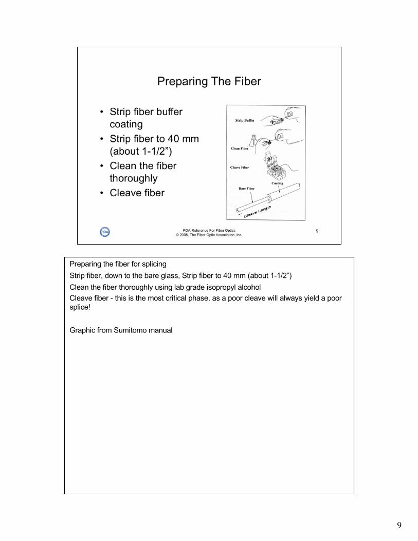
Preparing the fiber for splicingStrip fiber, down to the bare glass, Strip fiber to 40 mm (about 1-1/2”)Clean the fiber thoroughly using lab grade isopropyl alcoholCleave fiber - this is the most critical phase, as a poor cleave will always yield a poor splice!
Graphic from Sumitomo manual

10
Stripping fibers is the most critical phase of splicing where fiber damage is most likely to occur.Try to avoid nicks or cuts as it weakens fiber and can cause long term reliability problemsStrip 900 micron buffer first, then 250 micron, both in one step. To minimize fiber nicks, strip in one step instead of little bites as done with connectors.Be careful cleaning the fiber and placing it in holders for cleaving or splicing too

11
Place an alcohol pad (or lint-free wipe with pure isopropyl alcohol) between your thumb and forefinger, and wipe the fiber between them.Careful- do not break the fiber!

12
Cleaving - Step 1Open the two clamps on the cleaverMake sure it is completely clean

13
Cleaving -Step 2Gently lay the fiber into the left side of the cleaverEnd of the buffer should be at the 16 mm mark

14
Cleaving - Step 3
Close the clamp to hold the fiber buffer in place

15
Cleaving - Step 4First check to see the fiber is straight and in the middle of the pad indicated by the arrowMove the scribe wheel to the front of the cleaverGently close the right clamp to hold the fiber

16
Cleaving - Step 5Push the button on the front of the cleaver to slide the cleave wheel to the rear, which will scribe the fiber

17
Cleaving - Step 6Push the button on the top of the cleaver to cleave the fiber

18
Cleaving - Step 7Open the cleaver clamp to remove the fiberPick up the fiber scrap with tweezers and dispose of properlyOpen the left clamp and remove the fiber
19
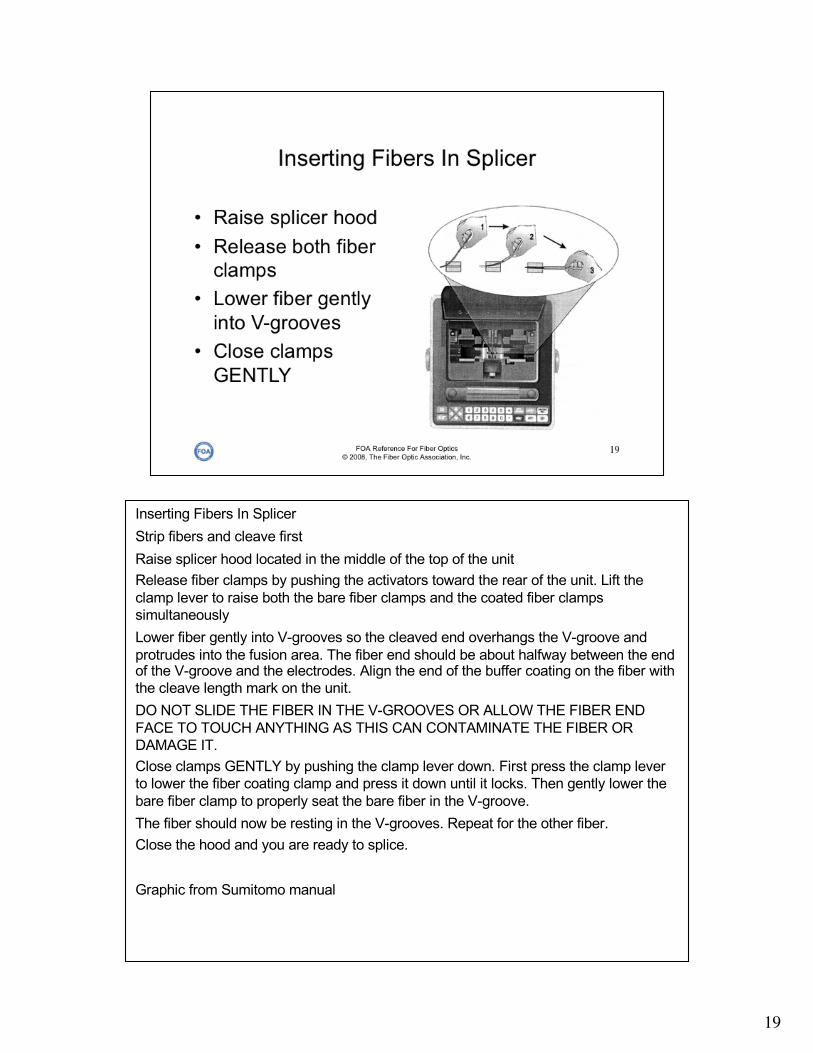
Inserting Fibers In Splicer Strip fibers and cleave firstRaise splicer hood located in the middle of the top of the unitRelease fiber clamps by pushing the activators toward the rear of the unit. Lift the clamp lever to raise both the bare fiber clamps and the coated fiber clamps simultaneouslyLower fiber gently into V-grooves so the cleaved end overhangs the V-groove and protrudes into the fusion area. The fiber end should be about halfway between the end of the V-groove and the electrodes. Align the end of the buffer coating on the fiber with the cleave length mark on the unit.DO NOT SLIDE THE FIBER IN THE V-GROOVES OR ALLOW THE FIBER END FACE TO TOUCH ANYTHING AS THIS CAN CONTAMINATE THE FIBER OR DAMAGE IT.Close clamps GENTLY by pushing the clamp lever down. First press the clamp lever to lower the fiber coating clamp and press it down until it locks. Then gently lower the bare fiber clamp to properly seat the bare fiber in the V-groove.The fiber should now be resting in the V-grooves. Repeat for the other fiber. Close the hood and you are ready to splice.
Graphic from Sumitomo manual

20
Loading Fibers - Step 1Gently lay the fiber in the guides on the splicerNote the position of the end of the buffer coating - at the 16 mm markCheck the position of the fiber end - should be near the electrodes

21
Loading Fibers - Step 2Gently lower the first clamp to hold the buffer coating in placeMake certain the fiber is still in position in the v-groove near the electrodes

22
Loading Fibers - Step 3Check again that the fiber is in the V-groove and the end is near the electrodesClose the clamp that holds the fiber

23
Loading Fibers - Step 4Repeat for the other fiber being spliced

24
Run Splicer Program - Step 1Close hood on fibersDisplay should show “SPLICE MODE MENU” and “AUTOMATIC MODE”

25
Run Splicer Program - Step 2Close hood on fibersDisplay should show “SPLICE MODE MENU” and “AUTOMATIC MODE”Press “SET” to begin splicingSpicer will move fiber into place and show fiber on screen

26
Run Splicer Program - Step 3Spicer will move fiber into place and show fiber on screenDuring the process, screen will show fiber placement and messages will display to show progress:GAP ADJUST - the splicer is setting end gapFOCUS - adjusting the camera focusSPLATTERING - pre-fusing the fibers to polish the fiber endsFIBER END CHECK - checks the cleave angle and cleanlinessFIELD CHANGE - changes from X to Y imageCORE ALIGN/DIAMETER ALIGN - aligns the fibers according to the chosen programARC FUSION - fuses the fibers by heating the ends in an arc and feeding them togetherINSPECTION - High-resolution Direct Core Monitoring (HDCM) to evaluate the splice quality using the cameraES LOSS - displays the estimated loss in dB and any observed defects

27
Run Splicer Program - Step 4 When finished running program, splicer will show splice loss estimate at top of screen and say “OPEN HOOD”The splicing process is finished

28
Visually inspect spliceUse both X and Y views (FIELD CHANGE)Some flaws that do not affect optical transmission are acceptable, as shownSome fibers (e.g. fluorine-doped or titanium coated) may cause white or black lines in splice region that are not faults
Graphic from Sumitomo manual

29
Some flaws are unacceptable and require starting the splicing process overSome, like black spots or lines, can be improved by repeating the ARC step, but never more than twiceFor large core offsets, bubbles or bulging splices, always redo
Graphic from Sumitomo manual
30
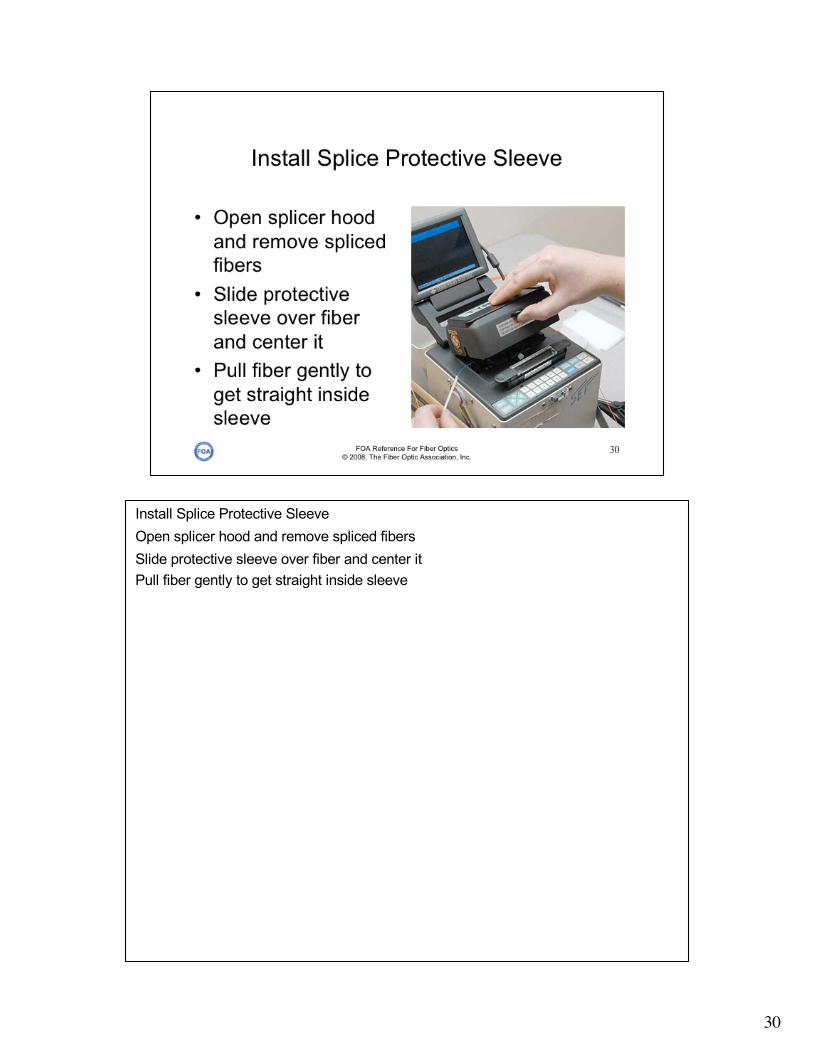
Install Splice Protective SleeveOpen splicer hood and remove spliced fibersSlide protective sleeve over fiber and center itPull fiber gently to get straight inside sleeve

31
The heater for the sleeve is at the front of the splicerOpen heater clamps on both sidesCenter sleeve in heater chamberLower fiber into heater Close doors and secure magnetically

32
Center sleeve in heater chamberLower fiber into heater Close doors and secure magnetically - NOTE: When using 900 micron buffered fiber, do not snap heater doors closed, just shut gently, since they can damage fibers if snapped shut!
Once heater cycle is started, you can begin another splice while it is operating.

33
Press HEATER SET to start heater cycleBeep after about 90 seconds indicates cycle is completedLift open both clampsRemoved splice while pulling gently on fibers to keep straightCareful - sleeve is hot!
Once heater cycle is started, you can begin another splice while it is operating.
34
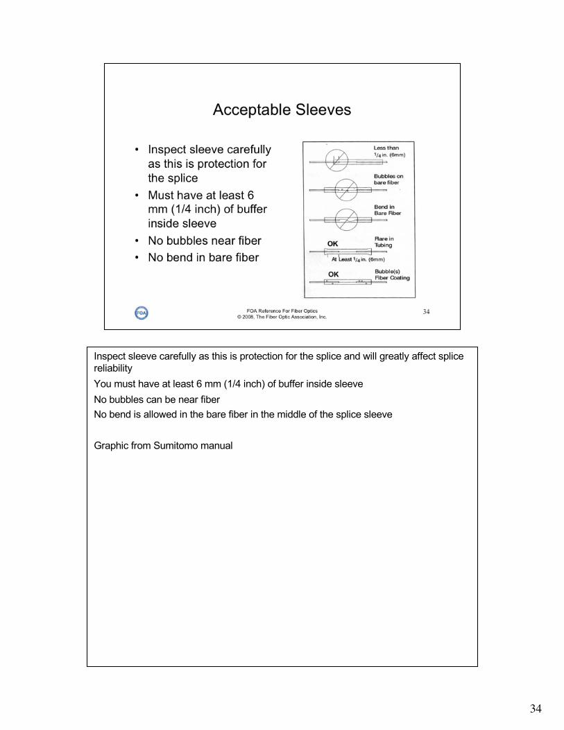
Inspect sleeve carefully as this is protection for the splice and will greatly affect splice reliabilityYou must have at least 6 mm (1/4 inch) of buffer inside sleeveNo bubbles can be near fiberNo bend is allowed in the bare fiber in the middle of the splice sleeve
Graphic from Sumitomo manual

35
ConstrictionCurrent too highFeed rate too slowPrefusion time too longPrefusion current too highGap too wideContaminated electrodes

36
EnlargementAutofeed too fastIncorrect current

37
Bubble or InclusionContaminated fiber end facesPoor cleaveFusion current too highPrefusion current or time too low

38
MatchheadsContaminated electrodesFusion current much too highPrefusion time much too longPrefusion current much too highAutofeed too smallGap too large

39
Not fused throughFusion current too lowPrefusion time too short

40
If the fibers look like this, recleave!These fibers were not cleaved properly and the splicer will not try to splice them.

Some fusion splicers can splice connectors directly onto fiber using a factory-made connector with a short fiber pigtail. See the FOA VHO on Prepolished/ Splice Connectors for details on this termination method.
41

42