this document was prepared and published by educational...
TRANSCRIPT

This document was prepared and published by Educational Services Development andPublishing, Digital Equipment Corporation.

Installing and UsingThe VT1000 Video TerminalOrder Number EK–V1000–UG–002
Digital Equipment Corporation

First Edition, February 1990 Second Edition, June 1990
The information in this document is subject to change without notice and should notbe construed as a commitment by Digital Equipment Corporation. Digital EquipmentCorporation assumes no responsibility for any errors that may appear in this document.
The software described in this document is furnished under a license and may be used orcopied only in accordance with the terms of such license.
No responsibility is assumed for the use or reliability of software on equipment that is notsupplied by Digital Equipment Corporation or its affiliated companies.
Restricted Rights: Use, duplication, or disclosure by the U. S. Government is subject torestrictions as set forth in subparagraph ( c ) ( 1 ) ( ii ) of the Rights in Technical Dataand Computer Software clause at DFARS 252.227–7013.
Copyright © by Digital Equipment Corporation 1990
All Rights Reserved.Printed in Taiwan.
FCC NOTICE: The equipment described in this manual generates, uses, and may emitradio frequency energy. The equipment has been type tested and found to comply withthe limits for a Class A computing device pursuant to Subpart J of Part 15 of FCCRules, which are designed to provide reasonable protection against such radio frequencyinterference when operated in a commercial environment. Operation of this equipment ina residential area may cause interference, in which case the user at his own expense maybe required to take measures to correct the interference.
AT&T and UNIX are trademarks of the American Telephone and Telegraph Company.
X Window System is a trademark of the Massachusetts Institute of Technology.
The following are trademarks of Digital Equipment Corporation:DEC DECwindows PDP ThinWireDECall DECwriter P/OS ULTRIXDECconnect DIBOL Professional ULTRIX-32DECmailer LA Q-bus UNIBUSDECmate LA50 Q22-bus VAXDECnet LA75 Companion Rainbow VAXstationDECserver LN01, LN03 ReGIS VMSDECservice LN03 PLUS RSTS VR150DECstation LQP02 RSX VT, VT52, VT100DECsupport MASSBUS RT VT220, VT320, VT420DECterm MicroPDP Scholar VT1000DECUS MicroVAX SERVIcenter
dt
Contents
About This Guide xi
1 A Look at the TerminalVT1000 Components . . . . . . . . . . . . . . . . . . . . . . . . . . . . . . . . . . . . 1
System Box . . . . . . . . . . . . . . . . . . . . . . . . . . . . . . . . . . . . . . . . . 2Monitor . . . . . . . . . . . . . . . . . . . . . . . . . . . . . . . . . . . . . . . . . . . . 2Keyboard . . . . . . . . . . . . . . . . . . . . . . . . . . . . . . . . . . . . . . . . . . . 3Mouse . . . . . . . . . . . . . . . . . . . . . . . . . . . . . . . . . . . . . . . . . . . . . 3
X Window Sessions and Video Terminal Sessions . . . . . . . . . . . . . . 3X Window System and DECwindows . . . . . . . . . . . . . . . . . . . . . . 3
System Requirements . . . . . . . . . . . . . . . . . . . . . . . . . . . . . . . . . . . 4VMS Systems: LAT Protocol . . . . . . . . . . . . . . . . . . . . . . . . . . . . 4UNIX and ULTRIX Systems: TCP/IP TELNET Protocol . . . . . . . 4
How the VT1000 Works . . . . . . . . . . . . . . . . . . . . . . . . . . . . . . . . . . 5VT1000 Terminal Highlights . . . . . . . . . . . . . . . . . . . . . . . . . . . . . . 6
Customizing Your Terminal . . . . . . . . . . . . . . . . . . . . . . . . . . . . . 7Compatibility with VT Series Terminals . . . . . . . . . . . . . . . . . . . 7Character Sets . . . . . . . . . . . . . . . . . . . . . . . . . . . . . . . . . . . . . . . 7
Programming the VT1000 Terminal . . . . . . . . . . . . . . . . . . . . . . . . . 7
iii

iv Contents
Installing Your VT1000 Video Terminal
2 Installing Your TerminalSite Preparation . . . . . . . . . . . . . . . . . . . . . . . . . . . . . . . . . . . . . . . . 11
Selecting a Location . . . . . . . . . . . . . . . . . . . . . . . . . . . . . . . . . . . 13Installation . . . . . . . . . . . . . . . . . . . . . . . . . . . . . . . . . . . . . . . . . . . 14Installing Memory . . . . . . . . . . . . . . . . . . . . . . . . . . . . . . . . . . . . . . 21
Installing the RAM Memory Controller Board . . . . . . . . . . . . . . . 24Installing the ROM Board . . . . . . . . . . . . . . . . . . . . . . . . . . . . . . 28
3 Getting StartedVT1000 Terminal Manager Window . . . . . . . . . . . . . . . . . . . . . . . . . 32Choosing the Display Language . . . . . . . . . . . . . . . . . . . . . . . . . . . . 32Choosing the Correct Keyboard Type . . . . . . . . . . . . . . . . . . . . . . . . 33Starting a Session on Your Host System . . . . . . . . . . . . . . . . . . . . . 35
Starting a Video Terminal or X Window Sessionon a VMS System . . . . . . . . . . . . . . . . . . . . . . . . . . . . . . . . . . . . . 36Starting a Video Terminal or X Window Sessionon an ULTRIX or UNIX System . . . . . . . . . . . . . . . . . . . . . . . . . . 41Starting a Video Terminal Session on the Serial Host Port . . . . . 47
Ending a Session . . . . . . . . . . . . . . . . . . . . . . . . . . . . . . . . . . . . . . . 47
Using Your VT1000 Video Terminal
4 Using WindowsDECwindows Differences . . . . . . . . . . . . . . . . . . . . . . . . . . . . . . . . . 51Before You Start . . . . . . . . . . . . . . . . . . . . . . . . . . . . . . . . . . . . . . . . 52
Using the Mouse . . . . . . . . . . . . . . . . . . . . . . . . . . . . . . . . . . . . . 52What Are Windows? . . . . . . . . . . . . . . . . . . . . . . . . . . . . . . . . . . . 53
Using Windows . . . . . . . . . . . . . . . . . . . . . . . . . . . . . . . . . . . . . . . . 54Selecting Windows . . . . . . . . . . . . . . . . . . . . . . . . . . . . . . . . . . . . 55Moving Windows . . . . . . . . . . . . . . . . . . . . . . . . . . . . . . . . . . . . . 55Changing the Size of Windows . . . . . . . . . . . . . . . . . . . . . . . . . . . 56Shrinking Windows to Icons . . . . . . . . . . . . . . . . . . . . . . . . . . . . . 57Expanding Icons to Windows . . . . . . . . . . . . . . . . . . . . . . . . . . . . 58

Contents v
Stacking Overlapping Windows . . . . . . . . . . . . . . . . . . . . . . . . . . 59Choosing Items from Pull-Down Menus . . . . . . . . . . . . . . . . . . . . . . 59Supplying Information in Dialog Boxes . . . . . . . . . . . . . . . . . . . . . . 60
Moving and Changing Settings in a Dialog Box . . . . . . . . . . . . . . 62Using Scroll Bars . . . . . . . . . . . . . . . . . . . . . . . . . . . . . . . . . . . . . . . 63
5 Using Video Terminal (VTE) WindowsVTE Window Format . . . . . . . . . . . . . . . . . . . . . . . . . . . . . . . . . . . . 66Clearing, Resetting, or Leaving the Session . . . . . . . . . . . . . . . . . . . 68Copying and Pasting Text . . . . . . . . . . . . . . . . . . . . . . . . . . . . . . . . 69
Host Synchronization Required . . . . . . . . . . . . . . . . . . . . . . . . . . 70Selecting Text to Copy . . . . . . . . . . . . . . . . . . . . . . . . . . . . . . . . . 71Pasting Text . . . . . . . . . . . . . . . . . . . . . . . . . . . . . . . . . . . . . . . . . 71Using QuickCopy . . . . . . . . . . . . . . . . . . . . . . . . . . . . . . . . . . . . . 72
Customizing the VTE Window . . . . . . . . . . . . . . . . . . . . . . . . . . . . . 72Displaying the Customize Menu . . . . . . . . . . . . . . . . . . . . . . . . . 73Saving and Recalling Settings . . . . . . . . . . . . . . . . . . . . . . . . . . . 74Changing Your VTE Window Settings . . . . . . . . . . . . . . . . . . . . . 75Changing Your VTE Display Settings . . . . . . . . . . . . . . . . . . . . . 78Changing Your VTE General Operating Features . . . . . . . . . . . . 80Changing Your VTE Keyboard Features . . . . . . . . . . . . . . . . . . . 84Choosing National Replacement Character Sets . . . . . . . . . . . . . 86Printing from a Video Terminal Window . . . . . . . . . . . . . . . . . . . 87
6 Using the VT1000 Terminal ManagerVT1000 Terminal Manager Window . . . . . . . . . . . . . . . . . . . . . . . . . 91Creating Sessions on a Host System . . . . . . . . . . . . . . . . . . . . . . . . 93
Creating a Video Terminal Window on a VMS System . . . . . . . . . 95Creating an X Window Session on a VMS System . . . . . . . . . . . . 100Creating a Video Terminal Window or X Window Session on anULTRIX or UNIX System . . . . . . . . . . . . . . . . . . . . . . . . . . . . . . 102Creating a Video Terminal Window on the Host or Printer Port(VMS, ULTRIX, or UNIX) . . . . . . . . . . . . . . . . . . . . . . . . . . . . . . 104Creating a TCP/IP X Window Session . . . . . . . . . . . . . . . . . . . . . 105
Pausing or Ending Sessions . . . . . . . . . . . . . . . . . . . . . . . . . . . . . . . 106Pausing a Session . . . . . . . . . . . . . . . . . . . . . . . . . . . . . . . . . . . . 106

vi Contents
Ending a Session . . . . . . . . . . . . . . . . . . . . . . . . . . . . . . . . . . . . . 108Customizing Your VT1000 Environment . . . . . . . . . . . . . . . . . . . . . 110Printing the Screen . . . . . . . . . . . . . . . . . . . . . . . . . . . . . . . . . . . . . 110
7 Customizing the VT1000 Terminal ManagerDisplaying the Customize Menu . . . . . . . . . . . . . . . . . . . . . . . . . . . 113Saving and Recalling Settings . . . . . . . . . . . . . . . . . . . . . . . . . . . . . 114Changing Your Keyboard Settings . . . . . . . . . . . . . . . . . . . . . . . . . . 115Choosing the Display Language . . . . . . . . . . . . . . . . . . . . . . . . . . . . 118Changing Your Pointer and Mouse Settings . . . . . . . . . . . . . . . . . . . 119Changing Your Print Screen Settings . . . . . . . . . . . . . . . . . . . . . . . . 120Changing Your Security Settings . . . . . . . . . . . . . . . . . . . . . . . . . . . 122Locking Your Customize Dialog Boxes . . . . . . . . . . . . . . . . . . . . . . . 125Activating Customize Password Security . . . . . . . . . . . . . . . . . . . . 128Changing Your Window Settings . . . . . . . . . . . . . . . . . . . . . . . . . . . 129Controlling the Display of Messages . . . . . . . . . . . . . . . . . . . . . . . . 132Changing Your Host Port or Printer Port Settings . . . . . . . . . . . . . . 134Changing Your LAT Settings . . . . . . . . . . . . . . . . . . . . . . . . . . . . . . 138Changing Your TCP/IP Settings (ULTRIX and UNIX Systems) . . . . 142Changing Your TCP/IP Name Server Settings . . . . . . . . . . . . . . . . . 144Changing Your TCP/IP Routing Table Settings . . . . . . . . . . . . . . . . 145Changing Your Font Path Settings . . . . . . . . . . . . . . . . . . . . . . . . . 147
8 The KeyboardLK401 Keyboard . . . . . . . . . . . . . . . . . . . . . . . . . . . . . . . . . . . . . . . 151
Keyboard Dialect . . . . . . . . . . . . . . . . . . . . . . . . . . . . . . . . . . . . . 151Layout . . . . . . . . . . . . . . . . . . . . . . . . . . . . . . . . . . . . . . . . . . . . . 151
Main Keypad . . . . . . . . . . . . . . . . . . . . . . . . . . . . . . . . . . . . . . . . . . 152Editing Keypad . . . . . . . . . . . . . . . . . . . . . . . . . . . . . . . . . . . . . . . . 155Numeric Keypad . . . . . . . . . . . . . . . . . . . . . . . . . . . . . . . . . . . . . . . 155Top-Row Function Keys . . . . . . . . . . . . . . . . . . . . . . . . . . . . . . . . . . 156
Data Processing Keys . . . . . . . . . . . . . . . . . . . . . . . . . . . . . . . . . . 157Compose Characters . . . . . . . . . . . . . . . . . . . . . . . . . . . . . . . . . . 158
Indicator Lights . . . . . . . . . . . . . . . . . . . . . . . . . . . . . . . . . . . . . . . . 158Audible Indicators . . . . . . . . . . . . . . . . . . . . . . . . . . . . . . . . . . . . . . 159

Contents vii
Keyclick . . . . . . . . . . . . . . . . . . . . . . . . . . . . . . . . . . . . . . . . . . . . 159Bell . . . . . . . . . . . . . . . . . . . . . . . . . . . . . . . . . . . . . . . . . . . . . . . 159
9 Typing Additional CharactersWhat Characters Can I Type? . . . . . . . . . . . . . . . . . . . . . . . . . . . . . 161Key Sequences with Nonspacing Diacritical Keys . . . . . . . . . . . . . . 161How to Type a Character Using the Compose Character Key . . . . . 162How to Type a Character Using the Group Shift Key . . . . . . . . . . . 162Invalid Sequences . . . . . . . . . . . . . . . . . . . . . . . . . . . . . . . . . . . . . . 163
Canceling or Restarting a Key Sequence . . . . . . . . . . . . . . . . . . . 163Hexadecimal Key Sequences . . . . . . . . . . . . . . . . . . . . . . . . . . . . . . 164
10 VT1000 VTE Programming SummaryLocator Device Commands . . . . . . . . . . . . . . . . . . . . . . . . . . . . . . . . 169
Enable Filter Rectangle (DECEFR) . . . . . . . . . . . . . . . . . . . . . . . 170Enable Locator Reports (DECELR) . . . . . . . . . . . . . . . . . . . . . . . 171Locator Report (DECLRP) . . . . . . . . . . . . . . . . . . . . . . . . . . . . . . 172Request Locator Position (DECRQLP) . . . . . . . . . . . . . . . . . . . . 174Select Locator Events (DECSLE) . . . . . . . . . . . . . . . . . . . . . . . . 175
Programming Summary . . . . . . . . . . . . . . . . . . . . . . . . . . . . . . . . . . 176
11 Solving Problems and Getting ServiceOperating Problems . . . . . . . . . . . . . . . . . . . . . . . . . . . . . . . . . . . . . 183Power-Up Self-Test . . . . . . . . . . . . . . . . . . . . . . . . . . . . . . . . . . . . . . 187
Screen Error Messages . . . . . . . . . . . . . . . . . . . . . . . . . . . . . . . . . 187Digital Service . . . . . . . . . . . . . . . . . . . . . . . . . . . . . . . . . . . . . . . . . 188How To Get Service . . . . . . . . . . . . . . . . . . . . . . . . . . . . . . . . . . . . . 189
A SpecificationsSite Planning . . . . . . . . . . . . . . . . . . . . . . . . . . . . . . . . . . . . . . . . . . 190Environment . . . . . . . . . . . . . . . . . . . . . . . . . . . . . . . . . . . . . . . . . . 191Electrical . . . . . . . . . . . . . . . . . . . . . . . . . . . . . . . . . . . . . . . . . . . . . 191Display (Monochrome Monitors) . . . . . . . . . . . . . . . . . . . . . . . . . . . . 192LK401 Keyboard . . . . . . . . . . . . . . . . . . . . . . . . . . . . . . . . . . . . . . . 192
viii Contents
B Options and DocumentationOptional Memory Boards . . . . . . . . . . . . . . . . . . . . . . . . . . . . . . . . . 194Modems . . . . . . . . . . . . . . . . . . . . . . . . . . . . . . . . . . . . . . . . . . . . . . 194Cables . . . . . . . . . . . . . . . . . . . . . . . . . . . . . . . . . . . . . . . . . . . . . . . 195Related Documentation . . . . . . . . . . . . . . . . . . . . . . . . . . . . . . . . . . 195Ordering Information . . . . . . . . . . . . . . . . . . . . . . . . . . . . . . . . . . . . 196
C CommunicationNetwork Protocols . . . . . . . . . . . . . . . . . . . . . . . . . . . . . . . . . . . . . . 197Serial Communication . . . . . . . . . . . . . . . . . . . . . . . . . . . . . . . . . . . 198
Serial Communication Cables . . . . . . . . . . . . . . . . . . . . . . . . . . . 199Serial XON/XOFF Flow Control . . . . . . . . . . . . . . . . . . . . . . . . . . 199
Modems . . . . . . . . . . . . . . . . . . . . . . . . . . . . . . . . . . . . . . . . . . . . . . 200Modem Connections and Disconnections . . . . . . . . . . . . . . . . . . . 200
Break Function . . . . . . . . . . . . . . . . . . . . . . . . . . . . . . . . . . . . . . . . 201Communication Connector Signals . . . . . . . . . . . . . . . . . . . . . . . . . . 201Pin Signals for the Pointing Device Connector . . . . . . . . . . . . . . . . . 203Standards . . . . . . . . . . . . . . . . . . . . . . . . . . . . . . . . . . . . . . . . . . . . . 203
D System Management TasksPreparing the LAT Environment (VMS Systems) . . . . . . . . . . . . . . . 204Preparing the TCP/IP Environment (ULTRIX and UNIX Systems) . 205Running a Remote X Window Session on a VMS System . . . . . . . . . 214
Glossary
Index
Contents ix
Tables9–1 Keyboards with Diacritical Marks . . . . . . . . . . . . . . . . . . . . . 1619–2 Key Sequences for Additional Characters . . . . . . . . . . . . . . . 16610–1 Primary DA Alias Responses from the VT1000 . . . . . . . . . . . 18210–2 Control Function Requests (non-VT320) . . . . . . . . . . . . . . . . 18211–1 Operating Problems . . . . . . . . . . . . . . . . . . . . . . . . . . . . . . . . 183C–1 6-Pin DEC-423 Communication and Printer Interface Signals 202C–2 Pin Assignments for the Pointing Device Connector . . . . . . . 203

About This Guide
This guide is designed to help you install, operate, and maintain yourVT1000 video terminal. The guide provides information on how to open Xwindow or video terminal sessions on a VMS, ULTRIX, or UNIX system.
Who Should Use This GuideThis guide is for the installer and general user of the VT1000 videoterminal. The guide also provides programmers with a summary ofcontrol functions they can use when writing applications for videoterminal (VTE) windows.
OrganizationThis guide contains the following chapters and appendices:
• Chapter 1, ‘‘A Look at the Terminal,’’ provides an overview of theVT1000 terminal and its features.
• Chapter 2, ‘‘Installing Your Terminal,’’ describes how to install yourterminal and connect it to a host computer system. The chapter alsodescribes how to install optional RAM and ROM boards.
• Chapter 3, ‘‘Getting Started,’’ describes how to start a session on yourhost system. You can use the terminal with VMS, ULTRIX, or UNIXsystems.
• Chapter 4, ‘‘Using Windows,’’ describes how to to manipulate windows,choose menu items, and edit text. The chapter also shows how to usethe mouse.
• Chapter 5, ‘‘Using Video Terminal (VTE) Windows,’’ describes how touse video terminal (VTE) windows. VTE windows let you emulateDigital’s VT series of text terminals.
xi

xii About This Guide
• Chapter 6, ‘‘Using the VT1000 Terminal Manager,’’ describes how touse the VT1000 Terminal Manager window. You use this window tobegin and end sessions with a host system.
• Chapter 7, ‘‘Customizing the VT1000 Terminal Manager,’’ describeshow to customize the terminal’s operating settings for your computingenvironment and personal preference.
• Chapter 8, ‘‘The Keyboard,’’ describes the function of the keyboard’skeys, bells, and indicator lights.
• Chapter 9, ‘‘Typing Additional Characters,’’ describes how to entercharacters that do not appear as standard characters on yourkeyboard (for example, accented letters).
• Chapter 10, ‘‘VT1000 VTE Programming Summary,’’ providesprogrammers with a quick-reference summary of VT1000programming control functions for video terminal (VTE) windowapplications.
• Chapter 11, ‘‘Solving Problems and Getting Service,’’ describes how tosolve typical operating problems and directs you where to get morehelp.
• Appendix A, ‘‘Specifications,’’ lists VT1000 specifications.
• Appendix B, ‘‘Options and Documentation,’’ lists options, relateddocumentation, and ordering information.
• Appendix C, ‘‘Communication,’’ provides technical information oncommunication with a host computer system. The appendix describesnetwork protocols for LAT and TCP/IP connections, as well as serialcommunication.
• Appendix D, ‘‘System Management Tasks,’’ describes tasks for systemmanagers to perform before installing and running the terminal. Theappendix also describes how to run a remote X window session on aVMS system.
• The glossary defines new terms introduced in the text.

About This Guide xiii
ConventionsThe following conventions are used in this manual:
Mouse Refers to any pointing device, such as a mouse, a puck, or astylus.
MB1, MB2, andMB3
MB1 indicates the left mouse button. MB2 indicates themiddle mouse button. MB3 indicates the right mousebutton. (The buttons can be redefined by the user.)
Keyboard keys Keys or switches that are labeled appear in a box .
Example: Press the Return key.
Ctrl key For Ctrl key sequences, hold down Ctrl and press the otherkey.
Warnings Provide information to prevent personal injury.
Cautions Provide information to prevent damage to equipment orsoftware.
Notes Provide general information about the current topic.
Glossary entries Appear in italics when first used in text.
Note to the Reader
The screens and windows shown in this guide represent the latestinformation available at the time of publication. Some screens andwindows may not exactly match those that appear on your terminal.

1A Look at the Terminal
1
This chapter introduces you to the VT1000 video display terminal. Thechapter provides an overview of the terminal and its basic operatingfeatures. The chapter also tells you where to look in this manual for moreinformation about each feature.
The VT1000 lets you run X window applications on your computer system,including Digital’s DECwindows software. The VT1000 also providesvideo terminal (VTE) windows that are compatible with VT series textterminals.
You can use the VT1000 with one or more computer systems. The VT1000can work with computers that use the VMS, UNIX, or ULTRIX operatingsystems. You have several options for connecting your terminal to acomputer.
You can use a mouse or keyboard to send information to the host system.You can print data displayed on the screen by connecting a printer to theVT1000 system box or by using printers connected to your host system.
VT1000 ComponentsThe VT1000 terminal has four main components: a system box, monitor,keyboard, and mouse.
Chapter 1 1

2 A Look at the Terminal
G S F _ 0 8 2 1 _ 8 9 . D G
System Box
The VT1000 system box contains the terminal’s logic and memory boards.It also provides the connectors for power, system communication, andother devices. A cover panel attaches to the rear of the system box toconceal the connectors and cables. The system box is 368 mm deep 394mm wide 57 mm high (14.5 inches 15.5 inches 2.25 inches).
Monitor
The VT1000 comes with one of the following monochrome monitors:
VR150 (380 mm/15 inch) with tilt-swivel standVR262 (480 mm/19 inch) with stationary standVR315 (380 mm/15 inch) with tilt-swivel standVR319 (480 mm/19 inch) with tilt-swivel standVRE01 (480 mm/19 inch) flat panel display
Chapter 1
A Look at the Terminal 3
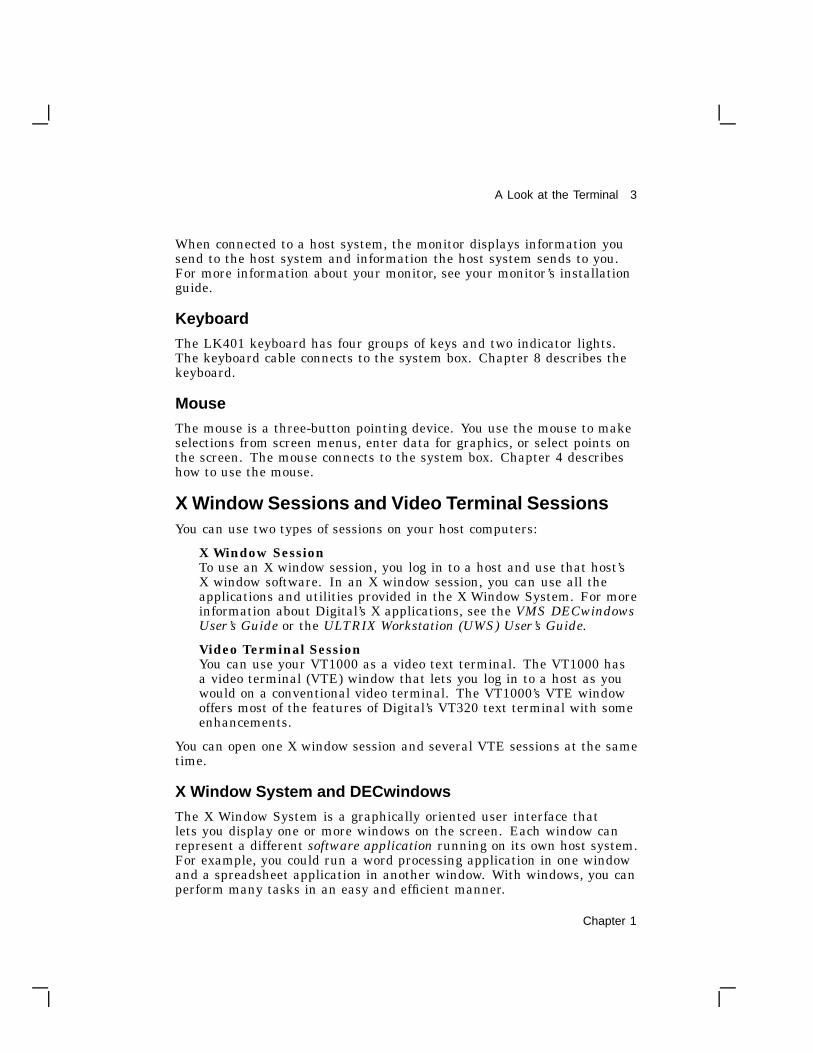
When connected to a host system, the monitor displays information yousend to the host system and information the host system sends to you.For more information about your monitor, see your monitor’s installationguide.
Keyboard
The LK401 keyboard has four groups of keys and two indicator lights.The keyboard cable connects to the system box. Chapter 8 describes thekeyboard.
Mouse
The mouse is a three-button pointing device. You use the mouse to makeselections from screen menus, enter data for graphics, or select points onthe screen. The mouse connects to the system box. Chapter 4 describeshow to use the mouse.
X Window Sessions and Video Terminal SessionsYou can use two types of sessions on your host computers:
X Window SessionTo use an X window session, you log in to a host and use that host’sX window software. In an X window session, you can use all theapplications and utilities provided in the X Window System. For moreinformation about Digital’s X applications, see the VMS DECwindowsUser’s Guide or the ULTRIX Workstation (UWS) User’s Guide.
Video Terminal SessionYou can use your VT1000 as a video text terminal. The VT1000 hasa video terminal (VTE) window that lets you log in to a host as youwould on a conventional video terminal. The VT1000’s VTE windowoffers most of the features of Digital’s VT320 text terminal with someenhancements.
You can open one X window session and several VTE sessions at the sametime.
X Window System and DECwindows
The X Window System is a graphically oriented user interface thatlets you display one or more windows on the screen. Each window canrepresent a different software application running on its own host system.For example, you could run a word processing application in one windowand a spreadsheet application in another window. With windows, you canperform many tasks in an easy and efficient manner.
Chapter 1

4 A Look at the Terminal
The X Window System was designed at the Massachusetts Instituteof Technology. Digital’s DECwindows software is based on and fullycompatible with the X Window System.
System RequirementsYou can use your terminal with the VMS, ULTRIX, and UNIX basedsystems.
VMS Systems: LAT Protocol
The VMS operating system is one of Digital’s operating systems. To makenetwork connections to a VMS host system, use the local area transport(LAT) protocol. LAT is a communications protocol for connecting to VMShost systems.
To open a video terminal (VTE) session: You can use any version of theVMS operating system.
To open an X window session: You must have VMS Version 5.3-1 or higherinstalled on your system, and your system manager must enable certainoptions (Appendix D).
UNIX and ULTRIX Systems: TCP/IP TELNET Protocol
The UNIX operating system was created by AT&T and is used throughoutthe computer industry. The ULTRIX operating system created by Digitialis based on the UNIX operating system. To make network connectionsto a UNIX or ULTRIX host, you normally use the transmission controlprogram/Internet protocol (TCP/IP) networking software. TCP/IP is thepreferred communication protocol for UNIX-based systems.
The VT1000 uses the TCP/IP TELNET protocol to make networkconnections to UNIX-based host systems. TELNET is the TCP/IP protocolthat lets terminals connect to host systems in a wide-area network.
To open a video terminal session: You can use any version of UNIX orULTRIX.
To open an X window session: You can use any version of UNIX to openan X window session, as long as any X11R3 client is installed on thathost. ULTRIX workstation (UWS) versions 2.1 and higher include anX11R3 client.
Chapter 1

A Look at the Terminal 5
How the VT1000 WorksYou can use the VT1000 with one or more computer systems. You haveseveral options for connecting your terminal to a computer. You canconnect the terminal directly to a computer through one of two serialports, or you can connect the terminal indirectly through an Ethernetnetwork using the ThinWire port.
The computer system you connect to is called the host. You can connectseveral VT1000 terminals to a single host or connect one VT1000 terminalto several hosts.
You use the keyboard and mouse to interact with applications on yoursystem. You send data to the application by typing on the keyboard orselecting window options with the mouse. Data sent by the applicationappears as text or graphics on the screen. You can print text or graphicsfrom the VT1000.
Chapter 1

6 A Look at the Terminal
You can use a variety of host software applications on the VT1000. Forexample, your host may have applications for word processing, data entry,programming, or business graphics. Most applications involve interactiveprocessing. This means the VT1000 immediately sends the informationyou enter from the mouse or keyboard to the host.
Applications use programming functions to perform many operations. TheVT1000 can work with standard American National Standards Institute(ANSI) functions. See Chapter 10.
VT1000 Terminal HighlightsThe VT1000 terminal is a four-piece desktop unit that provides manyof the features of a workstation. The VT1000 provides you with thefollowing features:
• A workstation-style display, resolution, keyboard, and mouse
• An X Window System desktop server for efficient interaction withDECwindows and X window applications
• A local window manager that lets you move and resize windows
• A local terminal manager that lets you create, manage, and deleteconnections to hosts
• A local video terminal (VTE) window that lets you use the VT1000 asa conventional video terminal
• Access to VMS, ULTRIX, and UNIX operating system software at thesame time
• Serial interfaces for a keyboard and a mouse or tablet
• Two serial lines with DEC-423 connectors for serial hostcommunication and printer support, like a traditional terminal
• A ThinWire Ethernet port to connect to an Ethernet network
• An optional RAM board that provides up to 3 megabytes of addedmemory storage
The RAM board is user installable.
Chapter 1

A Look at the Terminal 7
Customizing Your Terminal
The VT1000 lets you check and control the settings of the terminal’soperating features. You can
• Change individual feature settings.
• Recall factory-default settings or your own stored settings frommemory.
• Make temporary changes for the current session or store new settingsfor all future sessions.
Chapter 7 describes how to customize your VT1000.
Compatibility with VT Series Terminals
The VT1000 can operate as a video text terminal when you want to login to a host system as you would with a conventional video terminal. Youcan use the VT1000 as one of Digital’s VT320, VT220, VT102, VT101,or VT100 text terminals. Chapter 5 describes the video terminal (VTE)window and how to use it.
Character Sets
When you use video terminal (VTE) windows, you can choose differentcharacter sets to match your computer system or software applicationrequirements. You can choose from:
• Two 8-bit multinational character sets—DEC Multinational or thethe ISO Latin Alphabet No. 1 set of the International StandardsOrganization
• Several 7-bit national replacement character sets (NRCs) for WesternEuropean languages
Chapter 5 describes how to choose characters sets.
Programming the VT1000 TerminalThe VT1000 video terminal (VTE) windows emulate Digital’s VT320 textterminal. The VT320 Programmer Reference Manual explains the controlfunctions used to access the terminal’s video terminal (VTE) windowfeatures. Chapter 10 of this user guide is a summary of VT1000 specificcontrol functions and commands. Programmers use these functions intheir applications.
7

Installing YourVT1000Video Terminal

2Installing Your Terminal
2
This chapter provides step-by-step instructions on how to:
Prepare for installation.Unpack, inspect, and check the terminal’s components.Connect your terminal to a monitor, mouse, and keyboard.Connect your terminal to a network.Turn on your terminal.Connect an optional printer, modem, or tablet.Install an optional memory board.
Carefully read all installation instructions before you turn on the power.
Site PreparationBefore you install your VT1000 video terminal, make sure your computersystem has the necessary network hardware and system software tosupport the terminal. See your system manager to make sure theserequirements are met.
For System Managers
System managers need to prepare the system for use with the VT1000video terminal. Appendix D describes the required tasks.
Chapter 2 11

12 Installing Your Terminal
Network Hardware Support
The VT1000 video terminal requires one of the following physicalconnections to connect to a host computer system:
ThinWireconnector
Lets the VT1000 operate with X window applications and multipletext terminal sessions, using either the LAT or TCP/IP networkprotocol. You must use the ThinWire connector to operate with Xwindow or DECwindows software.
Serialline
Lets the VT1000 connect to a single host or terminal server as atraditional text terminal.
System Software Support
The following table summarizes the system resources needed to open Xwindow sessions or video terminal (VTE) sessions:
OperationOperatingSystem
CommunicationProtocol
Video terminal session VMS Version 4.0 LAT
UNIX (any version) TELNET (TCP/IP)
ULTRIX (any version)UWS Version 2.2
TELNET (TCP/IP)LAT
X window session VMS Version 5.3-1or higher
LAT
UNIX (any version) TCP/IPTFTP (UDP) for fontservice
UWS Version 2.1(includes ULTRIXVersion 3.1) or higher
TCP/IPTFTP (UDP) for fontservice
Chapter 2

Installing Your Terminal 13
Selecting a Location
Use the following guidelines to select a good location for your terminal:
• Select a surface area that is large enough to hold your system box,monitor, keyboard, and mouse.
• Select a location near ac power outlets and communication connectors.
• Keep your terminal away from heaters, photocopiers, direct sunlight,and abrasive particles.
• Do not block the air vents on the sides of the system box or place thesystem box on its side. Blocking the air vents can cause the system tooverheat.
• To avoid screen glare, select a place where bright light will not reflectoff the monitor.
• Place your monitor so that the top line of the monitor display is at eyelevel.
• Keep the air well circulated, to prevent excess heat and dust fromaccumulating.
• Keep the temperature between 10° and 40° C (50° and 104° F), andthe relative humidity between 10% and 95%.
• Keep the area clean. Do not place food or liquid on or near yourterminal.
Chapter 2

14 Installing Your Terminal
Installation
Unpack and check the contents of each carton.
1. Look for external damage on the shipping cartons, such as dents,holes or crushed corners.
2. Unpack the shipping cartons.
WARNINGIf necessary, use two people to lift or move the monitor out ofthe shipping carton. The approximate weight of the monitoris
• VR150 monitor (380 mm/15 inch): 16 kg (36 lb)
• VR262 monitor (480 mm/19 inch): 18 kg (40 lb)
• VR315 monitor (380 mm/15 inch): 13 kg (29 lb)
• VR319 monitor (480 mm/19 inch): 27 kg (60 lb)
• VRE01 monitor (480 mm/19 inch): 8 kg (15 lb)
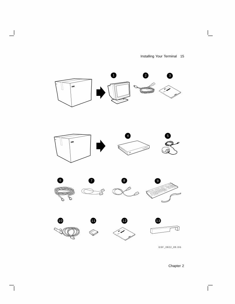
3. Make sure you have all the items shown in the following figure.Carefully inspect the components for shipping damage. If you havemissing or damaged items, contact your sales representative anddelivery agent.
CAUTIONIf you received optional memory boards, do not remove themfrom the antistatic bag at this time. Static electricity candamage memory boards.
4. Save the empty shipping cartons and packing material for repacking,in case you move or relocate your terminal.
Install any optional memory first.
If you ordered additional memory for your terminal, go to the ‘‘InstallingMemory ’’ section at the end of this chapter. You should install memoryboards in the system box before proceeding.
Chapter 2
Installing Your Terminal 15
TM
di ig t al
G S F _ 0 8 2 2 _ 8 9 . D G
121110
6 7 8
4 5
1 32
9
13
TM
Chapter 2

16 Installing Your Terminal
VT1000 Parts Checklist
!
Monitor: VR150, VR262, VR315, VR319, or VRE01
" System box power cord
# Monitor installation guide
$ System box
% Mouse
& DEC-423 communication cable
' Monitor cable
( Monitor power cord
) Keyboard and legend strip
+> Ethernet cable and connector
+? EIA adapter (DEC-423 6-pin to 25-pin)
+@ Installing and Using the VT1000 Video Terminal
+A Rear dress panel
Options (See ‘‘Installing Memory ’’ )
Memory controller board (comes with one SIMM card preinstalled)
SIMM card(s)
NOTEIf you receive three power cords (a short one and two long ones),the second long power cord is not needed for this installation.
Place the system box on a level surface. Place the monitoron top of the system box.
Leave enough room at the rear of the system box and monitor forconnecting cables.
WARNINGIf necessary, use two people to lift or move the monitor.
Chapter 2
Installing Your Terminal 17
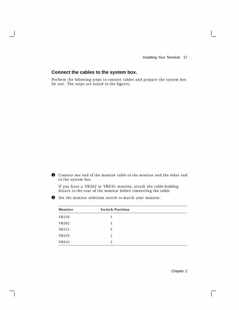
Connect the cables to the system box.
Perform the following steps to connect cables and prepare the system boxfor use. The steps are keyed to the figures.
! Connect one end of the monitor cable to the monitor and the other endto the system box.
If you have a VR262 or VRE01 monitor, attach the cable-holdingfixture to the rear of the monitor before connecting the cable.
" Set the monitor selection switch to match your monitor.
Monitor Switch Position
VR150 1
VR262 3
VR315 5
VR319 2
VRE01 3
Chapter 2
18 Installing Your Terminal
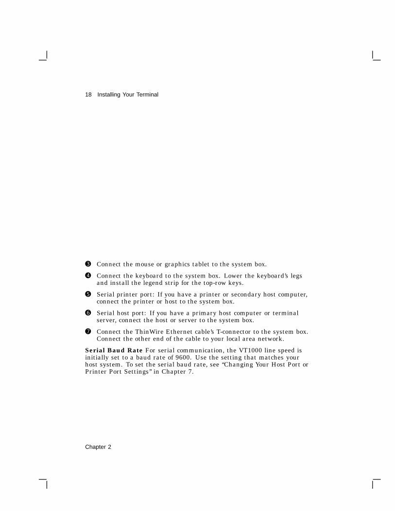
# Connect the mouse or graphics tablet to the system box.
$ Connect the keyboard to the system box. Lower the keyboard’s legsand install the legend strip for the top-row keys.
% Serial printer port: If you have a printer or secondary host computer,connect the printer or host to the system box.
& Serial host port: If you have a primary host computer or terminalserver, connect the host or server to the system box.
' Connect the ThinWire Ethernet cable’s T-connector to the system box.Connect the other end of the cable to your local area network.
Serial Baud Rate For serial communication, the VT1000 line speed isinitially set to a baud rate of 9600. Use the setting that matches yourhost system. To set the serial baud rate, see ‘‘Changing Your Host Port orPrinter Port Settings’’ in Chapter 7.
Chapter 2

Installing Your Terminal 19
( Make sure the | /O power switches on the system box and monitorare off (O). Then connect the long power cord to the system box and agrounded electrical outlet.
) Connect the short power cord to the monitor and the system box.
+> Route all cables under the dress panel. Then push the dress panelonto the rear of the system box.
+? Turn the monitor’s | /O power switch on by pressing ( | ). Turn thesystem box’s | /O power switch on by pressing ( | ).
The keyboard sounds a bell tone, and a pie graph gradually fills in asthe terminal performs its self-tests.
When the tests are done, the keyboard bell tone sounds again and theVT1000 Terminal Manager window appears.
Chapter 2

20 Installing Your Terminal
Final steps . . .
• If you had problems with the installation, review the installation stepscarefully. If the problem continues, refer to Chapter 11.
• This is a good time to set the brightness, contrast, and viewing angleof your monitor. See your monitor’s installation guide for instructions.
• If you installed optional RAM memory, use the procedure at the endof this chapter to verify that the system recognizes the additionalmemory.
Otherwise, the installation procedure is complete. You can go to Chapter 3to begin using your VT1000 video terminal.
Chapter 2

Installing Your Terminal 21
Installing MemoryThis section describes how to install memory boards in the system box.You can install
• Additional random access memory (RAM)
• A new read-only memory (ROM) board containing updated firmware
The VT1000 video terminal comes with 1 megabyte of RAM memory. Youcan add 1, 2, or 3 megabytes of optional RAM memory. Each megabyteof optional memory comes on a 1-megabyte single in-line memory module(SIMM) card. The SIMM cards install on the RAM memory controllerboard.
Unpack and check the contents of the box.
• If you are installing additional RAM memory, you receive amemory controller board with a 1-megabyte SIMM card installed. Ifyou ordered more than 1 megabyte of RAM memory, you also receiveone or two loose SIMM cards. Each SIMM card holds 1-megabyteof RAM memory. You will install the SIMM cards on the memorycontroller board later.
• If you are installing a ROM board, you receive a ROM board.
Carefully inspect the components for shipping damage. If you have anymissing or damaged items, contact your sales representative and deliveryagent.
CAUTIONThe memory boards and the SIMM cards can be damaged byelectrostatic discharge. Handle the memory board by its cover orstrap. Handle the SIMM card by the side edges of the card.
Chapter 2

22 Installing Your Terminal
Remove the system box cover.
1. Use a grounding wrist strap and an antistatic mat to perform theinstallation, if available. Otherwise, frequently touch the metalchassis of the system box during installation, to neutralize anyexisting static charges.
2. Turn the system box’s | /O power switch off (O).
3. Turn the monitor’s | /O power switch off (O).
4. Disconnect the two power cords from the rear of the system box.
5. Disconnect the monitor video cable from the rear of the monitor.
6. Remove the monitor from the top of the system box. You may needtwo people.
7. Release the top cover of the system box by pressing in the two pushtabs on the side of the box with the power switch, as shown.
8. Slowly lift the top cover until you release the hinges on the other sideof the box. Then lift the top cover completely off the system box.
22%
G S F _ 0 8 3 9 _ 8 9 . D G
12 3 4
56
Chapter 2

Installing Your Terminal 23
Identify the components in the system box.
There are four major components in the system box. The memorycontroller board is shown installed. SIMM cards install on the otherside of the memory controller board.
If you are installing optional RAM memory, go to the next section.
If you are installing a ROM board, go to the section ‘‘Installing theROM Board.’’
System Box Components
!
System logic board
" RAM memory controller board
# ROM board
$ Power supply
22%
G S F _ 1 3 6 2 _ 8 9 . D G
3
2
14
12 3 4
56
Chapter 2
24 Installing Your Terminal
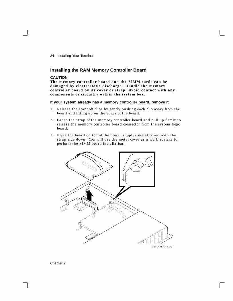
Installing the RAM Memory Controller Board
CAUTIONThe memory controller board and the SIMM cards can bedamaged by electrostatic discharge. Handle the memorycontroller board by its cover or strap. Avoid contact with anycomponents or circuitry within the system box.
If your system already has a memory controller board, remove it.
1. Release the standoff clips by gently pushing each clip away from theboard and lifting up on the edges of the board.
2. Grasp the strap of the memory controller board and pull up firmly torelease the memory controller board connector from the system logicboard.
3. Place the board on top of the power supply’s metal cover, with thestrap side down. You will use the metal cover as a work surface toperform the SIMM board installation.
G S F _ 0 9 5 7 _ 8 9 . D G
38%
Chapter 2

Installing Your Terminal 25
Install the SIMM cards on the memory controller board.If you ordered 1 megabyte of memory, you can skip this procedure. If youordered 2 or 3 megabytes of memory, you must install one or two SIMMcards on the memory controller board.
1. Remove the new memory controller board and the one or two smallSIMM cards from the shipping bag.
2. Place them on top of the power supply’s metal cover, with the strapside of the memory controller board facing down. Use the metalcover as a work surface to install the SIMM cards. This preventselectrostatic damage.
3. The memory controller board has one SIMM card preinstalled in theconnector labeled 2MB. Install the next SIMM card in the connectorlabeled 3MB and the last SIMM card in the connector labeled 4MB,as follows:
CAUTIONSIMM cards can be damaged by electrostatic discharge.Handle the SIMM card by the side edges of the card. Avoidcontact with the gold contact fingers on the card.
a. Insert the SIMM card into the connector at a 45-degree angle.Face the components on the SIMM card toward the componentson the memory controller board. Line up the center key slot onthe SIMM card with the connector key on the memory controllerboard.
b. Push down on the top of the SIMM card to securely seat the cardin the connector.
c. Raise the SIMM card into a standup position, until both sides ofthe card lock into the connector tabs.
Chapter 2
26 Installing Your Terminal
3MB
RAM_BOARD_EDIT.D
G a t 70%
4MB3MB
2MB
G S F _ 0 8 4 0 _ 8 9 . D G
3MB
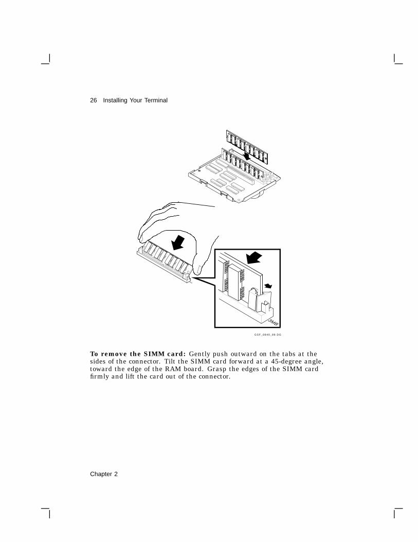
To remove the SIMM card: Gently push outward on the tabs at thesides of the connector. Tilt the SIMM card forward at a 45-degree angle,toward the edge of the RAM board. Grasp the edges of the SIMM cardfirmly and lift the card out of the connector.
Chapter 2
Installing Your Terminal 27
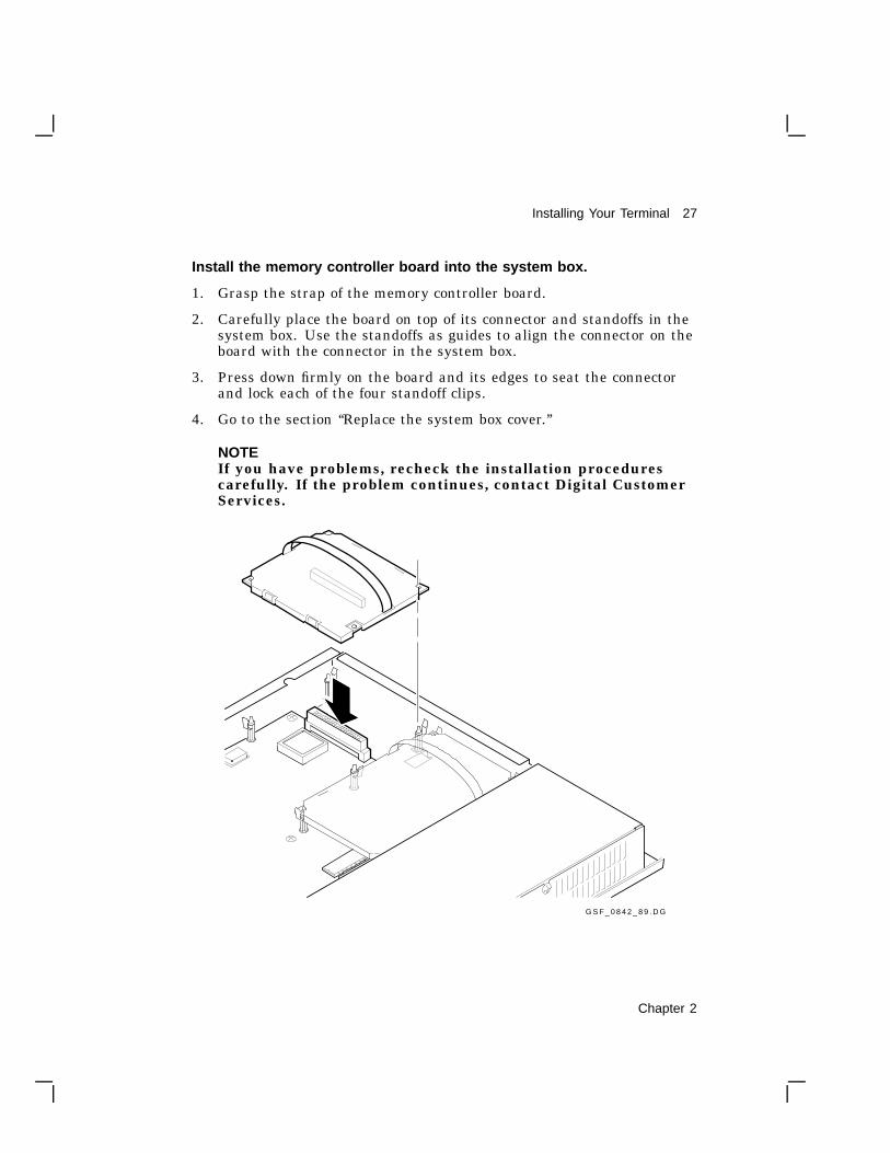
Install the memory controller board into the system box.
1. Grasp the strap of the memory controller board.
2. Carefully place the board on top of its connector and standoffs in thesystem box. Use the standoffs as guides to align the connector on theboard with the connector in the system box.
3. Press down firmly on the board and its edges to seat the connectorand lock each of the four standoff clips.
4. Go to the section ‘‘Replace the system box cover.’’
NOTEIf you have problems, recheck the installation procedurescarefully. If the problem continues, contact Digital CustomerServices.
G S F _ 0 8 4 2 _ 8 9 . D G
Chapter 2

28 Installing Your Terminal
Installing the ROM Board
CAUTIONThe ROM board can be damaged by electrostatic discharge.Handle the ROM board by its cover or strap. Also avoid contactwith any components or circuitry in the system box.
Remove the old ROM board from your system box.
1. Release the standoff clips by gently pushing each clip away from theboard and lifting up on the edges of the board.
2. Grasp the strap of the ROM board and pull up firmly to release theROM board connector from the system logic board.
3. Place the board on top of the power supply’s metal cover, with thestrap side down.
22% o f fu l l s i zethen imod sca led a t 1 .5
G S F _ 0 9 5 8 _ 8 9 . D G
Use REMOVE_ROM_BASE.DG fo r f i xes
38%
Chapter 2

Installing Your Terminal 29
Install the new ROM board into the system box.
1. Remove the new ROM board from the box and shipping bag.
2. Grasp the strap of the new ROM board.
3. Carefully place the board on top of the ROM connector and standoffsin the system box. Use the standoffs as guides to align the connectoron the board with the connector in the system box.
4. Press down firmly on the board and its edges to seat the connectorand lock each of the four standoff clips.
5. Continue to the next section to replace the system box cover.
Replace the system box cover.
1. From the rear of the system box, place the left side of the top coveronto the hinge tabs in the left side of the system box.
2. Gently lower the right side of the top cover onto the system box. Makesure the power connector frame slides into the slot behind the powerconnectors.
3. Push down on the right side of the top cover until it snaps into thetwo push tabs, locking it in place.
After Installing the Memory Controller Board or ROM Board...
If you are installing the VT1000 terminal, go back to the beginning of thischapter and continue the installation procedure.
If not, perform the following steps:
1. Place the monitor on top of the system box. Leave enough room toconnect cables on the rear of the system box and monitor.
2. Connect the two power cords to the rear of the system box.
3. Connect the monitor video cable to the rear of monitor.
4. Turn on the system box’s | /O power switch by pressing ( | ).
5. Turn on the monitor’s | /O power switch by pressing ( | ).
Chapter 2
30 Installing Your Terminal
Verifying the Installation of Optional RAM Memory
The VT1000 Terminal Manager window should be displayed on yourscreen.
Verify that the number on the right side of the Memory Remaining scaledisplays the correct number of total megabytes in your system.Standard + Optional = Number Displayed
1 megabyte 1 megabyte 2M
2 megabytes 3M
3 megabytes 4M
NOTEIf you have problems, recheck the installation procedurescarefully. If the problem continues, contact Digital CustomerServices.
The installation procedure for optional memory is complete.
Chapter 2

3Getting Started
3
This chapter provides step-by-step procedures on how to begin using yourterminal with a host computer. The chapter also introduces some of theVT1000 screens and menus.
If you are unfamiliar with using windows and a mouse, you may want toread the information in Chapter 4 before continuing.
Before you start, you should set the terminal to use the desired displaylanguage and keyboard type. By default, the terminal uses the Englishlanguage and the North American keyboard type.
You can use your VT1000 with the VMS, ULTRIX, or UNIX operatingsystems. You can open two types of sessions on these systems—a videoterminal session or X window session.
The chapter includes sections on:
• VT1000 Terminal Manager window
• Choosing the correct display language
• Choosing the correct keyboard type
• Opening a session on a VMS host system
• Opening a session on a UNIX or ULTRIX host system
• Ending a session
Chapter 3 31

32 Getting Started
VT1000 Terminal Manager WindowWhen you turn on the terminal, it displays the VT1000 Terminal Managerwindow after running some self-tests. You use the VT1000 TerminalManager window to start every session. The menu bar of this windowcontains the names of four pull-down menus: Session, Create, Customize,and Print Screen.
In this chapter, you will use the Session menu. Chapter 6 providesmore details on how to use the VT1000 Terminal Manager. Chapter 7describes how to customize the VT1000 Terminal Manager for yourworking environment.
Choosing the Display LanguageYou can display the VT1000 Terminal Manager window, system messages,and other menus in English, French, or German. The display language isinitially set to English.
To change the display language:
1. Turn on the terminal. The VT1000 Terminal Manager windowappears.
2. Point to the Customize menu name in the VT1000 TerminalManager’s menu bar. Click and hold MB1 to pull down the Customizemenu.
Chapter 3

Getting Started 33
3. In the Customize menu, drag the pointer to the Language . . . menuitem. Release MB1. The Customize Language dialog box appears.
GSF_1047_89.RAGS
4. In the Customize Language dialog box, click on the button next toyour language choice.
5. Click on the OK button to record your choice and dismiss theCustomize Language dialog box.
6. Save your setting so you do not have to enter it each time you turn onthe terminal.
• Pull down the Customize menu from the VT1000 TerminalManager’s menu bar.
• Choose the Save Current Settings menu item.
Choosing the Correct Keyboard TypeThe VT1000 has many keyboard types for different languagesand dialects. The terminal is initially set to work with the NorthAmerican/United Kingdom keyboard. If you have another keyboard,you must change the setting.
To change the keyboard type:
1. Turn on the terminal. The VT1000 Terminal Manager windowappears.
Chapter 3

34 Getting Started
2. Point to the Customize menu in the VT1000 Terminal Manager’smenu bar. Click and hold MB1 to pull down the Customize menu.
3. In the Customize menu, drag the pointer to the Keyboard . . . menuitem. Release MB1. The Customize Keyboard dialog box appears.
GSF_1046_89.RAGS
4. Turn the keyboard upside down and look for a label that specifies themodel number. The model number should be in a format similar toLK401-xx or nn-nnnnn-xx. Use the xx value to choose your keyboardtype from the Keyboard Type scroll box.
For example, if you have a British keyboard and the model number isLK401-AA, you choose LK401-AA British. (See Chapter 6 for details.)
5. In the Keyboard Type scroll box, click on the arrows until thekeyboard you want appears.
6. Click on the correct keyboard entry.
7. Click on the OK button to record your choice and dismiss theCustomize Keyboard dialog box.
Chapter 3
Getting Started 35
8. Save your setting so you do not have to enter it each time you turn onthe terminal.
• Pull down the Customize menu from the VT1000 TerminalManager’s menu bar.
• Choose the Save Current Settings menu item.
Starting a Session on Your Host SystemYou can use your terminal to open sessions on the VMS, ULTRIX, orUNIX operating systems.
You can run two types of sessions on a host computer with your terminal:
Video Terminal SessionsYou can use your VT1000 as a video text terminal. The VT1000has a video terminal (VTE) window that lets you log in to a hostas you would on a conventional video terminal. The VT1000’s VTEwindow offers the features of Digital’s VT320 terminal with someenhancements.
X Window SessionsTo use an X window session, you log in to a host and use that host’sX window software. In an X window session, you can use all theapplications and utilities provided in the X Window System.
You can run an X window session and a VTE session at the same time.The X window session appears in one window, while the VTE sessionappears in another. You can only run one X session at a time. You canrun several VTE sessions at a time.
The following sections show you how to:
• Start a video terminal or X window session on a VMS system.
• Start a video terminal or X window session on an ULTRIX or UNIXsystem.
• Start a video terminal session using the serial host port.
Chapter 3

36 Getting Started
Starting a Video Terminal or X Window Sessionon a VMS System
This section describes how to start a video terminal (VTE) or an X windowsession on a VMS host system, using a local area transport (LAT).
If you are using the VT1000 for the first time, you will need to enter oneor more LAT group codes to begin either type of session. If you want tobegin an X window session, you will also need to enter a LAT font path.
Your system manager can provide you with the group codes and font pathfor your network.
1. Turn on the terminal. The VT1000 Terminal Manager windowappears.
2. To connect to a host or service on the network, you need to enter andsave one or more LAT group codes in the terminal’s memory. If youhave already entered the group codes, go to step 6.
Point to the Customize menu name in the VT1000 TerminalManager’s menu bar. Click and hold MB1 to pull down the Customizemenu.
GSF_1710_89.RAGS
3. Drag the pointer to the LAT . . . menu item. Release MB1. TheCustomize LAT dialog box appears.
Chapter 3

Getting Started 37
4. Enter a group code into the Customize LAT dialog box.
• Use your keyboard to enter the group code into the text entryfield.
• Click on the Add button. The new group code appears in theGroup Codes scroll box.
• Repeat this procedure for each group code you want to add.
• Click on the OK button to dismiss the Customize LAT dialog box.
Chapter 3

38 Getting Started
5. Save your group code(s) so you do not have to enter them each timeyou turn on the terminal.
• Pull down the Customize menu from the VT1000 TerminalManager’s menu bar.
• Choose the Save Current Settings menu item.
6. If you want to begin an X window session, you need to enter and savea LAT font path. Some X applications require special character fontsto run properly. A font path lets the terminal access these characterfonts from a host. If you have already entered a font path, go to step9.
Pull down the Customize menu and choose the Font Path . . . menuitem. The Customize Font Path dialog box appears.
7. Enter a font path into the Customize Font Path dialog box.
• The LAT Font Path text entry field already has the word ROMentered. Enter a comma (,) followed by a font host name and twocolons.For example:
|ROM,BETA::------------------------------------
Chapter 3

Getting Started 39
• Click on the OK button to dismiss the Customize Font Path dialogbox.
You may have to wait several minutes before the message Set fontpath succeeded appears in the Messages area of the VT1000 TerminalManager window. Sometimes it takes a few minutes for the terminalto receive the message identifying the font path host. The terminalretries every 30 seconds for 2.5 minutes. If the wait is too long, yoursystem manager may be able to increase the host’s multicast messagefrequency.
8. Save the font path so you do not have to enter it each time you turnon the terminal.
• Pull down the Customize menu.
• Choose the Save Current Settings menu item.
9. Point to the Create menu name in the VT1000 Terminal Manager’smenu bar. Click and hold MB1 to pull down the Create menu.
10. To begin a VTE session, choose the LAT Terminal Window . . .menu item. The LAT Terminal Window Service Select dialog boxappears.
To begin an X window session, choose the LAT X Session . . . menuitem. The LAT X Session Service Select dialog box appears.
The two dialog boxes are similar. Here is the LAT Terminal WindowService Select dialog box:
Chapter 3

40 Getting Started
11. Choose a host system and connect to it.
The names of the hosts you can access appear in the scroll box at thetop of the dialog box. The host names should correspond to the groupcodes you have entered.
Step Result
1 Find the nameof the host youwant to log in to.If necessary, clickon the scroll barto display morenames.
Each time you click on the scroll bar, the scrollbox displays more host names if available.
Chapter 3

Getting Started 41
Step Result
NOTEYou may have to wait several minutes before the host you wantappears. Click on the Update Known Services button to update thescroll box. If the wait is too long, see your system manager.
2 Click on the nameof the host youwant to log into.
The host name becomes highlighted in the scrollbox and appears in the text entry field at thebottom of the window.
3 Click on the Addbutton.
The host name is added to the PreferredServices scroll box. You can add up to 4 hoststhat you frequently log in to.
4 Click on the Savebutton.
The VT1000 saves the host names you addedto the Preferred Services scroll box, so you donot have to enter them each time you turn yourterminal on.
5 In the PreferredServices scroll box,click on the hostyou want to connectto.
The host is selected for connection.
6 Click on theConnect button.
A video terminal (VTE) window or X windowlogin prompt appears. You may have to pressthe Return key several times before the loginprompt appears.
12. Log in to the VTE host or X window session with the same usernameand password you use for video terminal sessions. After you log in toan X window session, the host-based session manager starts up.
Starting a Video Terminal or X Window Sessionon an ULTRIX or UNIX System
This section describes how to start a video terminal (VTE) session oran X window session on a UNIX or ULTRIX host system, using TCP/IPTELNET or TCP/IP.
If you are using the VT1000 for the first time, you need the followinginformation before you begin a session:
• An IP address to assign to your terminal• One or more names or IP addresses for the host(s) you want to connect
to• A font path file (for X window sessions only)
Chapter 3

42 Getting Started
Your system manager can provide you with the IP addresses and a pointerto a font path file.
1. Turn on the terminal. The VT1000 Terminal Manager windowappears.
2. Determine if you have to assign an IP address to your terminal.
• If BOOTP address resolution is available on your system, yourterminal can determine its own IP address at power-up. Ask yoursystem manager. If BOOTP is available, you can go to step 8.
• If BOOTP is not available, continue with step 4 to enter yourterminal’s IP address.
3. Point to the Customize menu name in the VT1000 TerminalManager’s menu bar. Click and hold MB1 to pull down the Customizemenu.
GSF_1715_89.RAGS
4. Drag the pointer to the TCP/IP . . . menu item. Release MB1. TheCustomize TCP/IP dialog box appears.
Chapter 3

Getting Started 43
5. Enter an IP address and subnet mask.
• Enter your terminal’s IP address into the VT1000 IP Address(manual) text entry field.
• Enter your IP subnet mask into the IP Subnet Mask text entryfield.
• Click on the OK button to dismiss the Customize TCP/IP dialogbox.
6. Save your IP address and subnet mask so you do not have to enterthem each time you turn on the terminal.
• Pull down the Customize menu from the VT1000 TerminalManager window.
• Choose the Save Current Settings menu item.
7. If you are starting a video terminal (VTE) session, go to step 11.
If you are starting an X window session, perform the followingsteps to enter and save a font path in the VT1000 memory. If youhave already entered the font path, go to step 11.
Chapter 3

44 Getting Started
Some applications require special character fonts to run properly. Afont path lets the VT1000 access these character fonts. You need toenter and save a font path in the terminal’s memory. Your systemmanager can provide the font path for your VT1000.
To enter a font path, pull down the Customize menu and choose theFont Path . . . menu item. The Customize Font Path dialog boxappears.
8. Enter a font path into the Customize Font Path dialog box.
• Click on the TFTP Font Path button under the Font PathSelection title.
• The word ROMis already entered in the TFTP Font Path text entryfield. Enter a comma (,) a font host name or IP address, and a fontfile specification. See your system manager for the information toenter, if needed.For example:
|ROM,123.45.67.89:/vt1000/100dpi/fonts.dir--------------------------------------------
• Click on the OK button to dismiss the Customize Font Pathdialog box. A message appears in the Terminal Manager windowindicating the font path is being set.
Chapter 3
Getting Started 45
9. Save the font path so you do not have to enter it each time you turnon the terminal.
• Pull down the Customize menu from the VT1000 TerminalManager’s menu bar.
• Choose the Save Current Settings menu item.
10. Pull down the Create menu from the VT1000 Terminal Manager’smenu bar.
11. Choose the TELNET Terminal Window . . . menu item. TheTELNET Terminal Window Host Select dialog box appears.
Chapter 3

46 Getting Started
12. Under the IP Address and optional host name title, enter the IPaddress(es) or names of the host(s) you want to connect to. If yoursystem has Name Servers, only names are needed. Ask your systemmanager.
• Click on one of the text entry fields under the IP Address andoptional host name title. A text cursor appears.
• Enter the name or IP address of the host you want to connect to.Your system manager can provide you with IP addresses or namesfor the hosts on your network.
• Click on the Save button to save the information you enter, so youdo not have to enter them each time you turn the terminal on.
• Click on the button next to the name of the host you want toconnect to.
13. Click on the Connect button. A video terminal (VTE) windowappears.
14. Log in to the host as you would on a conventional video terminal.
15. If you want to run an X window application:
• Enter the appropriate commands to enable your terminal to runan X window application:
If you are using the C-shell
% setenv DISPLAY your_terminal’s_IP_address :0
If you are using the Bourne or Korn shell
$ DISPLAY=your_terminal’s_IP_address :0$ export DISPLAY
• Begin an X window application by entering the appropriatecommand. For example, the following command starts a DECtermapplication:
$ dxterm
• You can also run the DECwindows session manager from yourULTRIX host by entering one of the following commands:
Chapter 3

Getting Started 47
For UWS Version 2.1
$ dxsession -d your_terminal’s_IP_address :0
For UWS Version 2.2
$ dxsession
Starting a Video Terminal Session on the Serial Host Port
This section describes how to start a video terminal (VTE) session on aVMS, UNIX, or ULTRIX host system if you use the serial host port.
1. Turn on the terminal. The VT1000 Terminal Manager windowappears.
2. Point to the Create menu name in the VT1000 Terminal Managerwindow. Press and hold MB1 to pull down the Create menu.
3. Drag the pointer to the Terminal Window on Host Port menu item.Release MB1. A video terminal (VTE) window appears.
4. Press the Return key until the login prompt appears.
5. Log in to the host as you would on a conventional video terminal.
Ending a SessionYou can end a session at any point, by choosing the Quit menu item fromthe Session menu of either the VT1000 Terminal Manager or the remotesession manager. In both cases, choosing Quit returns the terminal to itsinitial start-up state.
End a session only after completing your work. When you end a session,the terminal:
• Terminates all host connections.• Deletes all windows on the screen.• Performs a complete software reset.• Displays the VT1000 terminal manager window.
To end your session:
1. Point to the Session menu name in the VT1000 Terminal Manager’smenu bar. Press and hold MB1 to pull down the menu.
Chapter 3

48 Getting Started
2. Click on the Quit menu item. A dialog box appears, asking you if youreally want to end the session.
• To end the session, click on the Yes button.
• To remain in the session, click on the No button.
48

Using YourVT1000Video Terminal

4Using Windows
4
This chapter describes how to use and manipulate VT1000 windows.
The chapter includes sections on:
• Using the mouse
• What are windows
• Selecting and manipulating windows
• Choosing items from pull-down menus
• Supplying information in dialog boxes
• Using scroll bars
DECwindows DifferencesThe windowing features of the VT1000 Terminal Manager are a subsetof the features available in the DECwindows window manager. Thefollowing features of the DECwindows window manager are not available:
• Ability to lock stacked windows in place
• Animation of icons shrinking or expanding
• Control of icon positions in the icon box
• Icon box pop-up menu
• Ability to control which window gets input focus when you expandicons (The expanded icon automatically gets input focus.)
Chapter 4 51

52 Using Windows
Before You StartWhen you work with windowing applications, you use your mouse toperform many operations—from making menu selections to manipulatingwindows on the screen.
Using the Mouse
Your mouse lets you move quickly and easily through windowingapplications. You simply point to an object on your screen and click abutton. The mouse has three buttons:
MB1 (mouse button 1) on the leftMB2 in the middleMB3 on the right
This button arrangement normally suits right-handed users. If you areleft-handed, you can reverse the position of MB1 and MB3 by changingthe Button Arrangement setting in the Customize Pointer dialog box(Chapter 7).
ZK−0250A−GE
MB1
MB2
MB3
Chapter 4

Using Windows 53
In X window applications, you can perform six basic actions with themouse.Point Move the mouse on your desk. This moves the cursor to
where you want the next action to occur.
Click Quickly press and release MB1. You should hear andfeel a faint click.
Press Point to a menu name or other item where you want theaction to occur. Without moving the mouse, press andhold MB1. If you are pointing at a menu name, pressingMB1 pulls down a menu and keeps it down until yourelease MB1.
Drag Press and hold MB1, move the pointer, and releaseMB1. For example, you drag a window outline to moveit to another place on your screen. To cancel a drag inprogress, click MB3 before releasing MB1. If you aredisplaying a pull-down menu, cancel the drag by movingthe pointer outside the menu.
Double click Point to the object and click MB1 twice in quicksuccession.
Shift click Point to the object. Press and hold the Shift key andclick MB1. Then release the Shift key.
You will get a chance to practice these movements when you open yourfirst session.
What Are Windows?
A window is an area on your screen that represents all or part of anapplication. You can use windows to view several applications at once.You can move windows on the screen, organizing information for easieruse. The video terminal (VTE) window is one of several windows availableon your VT1000 terminal.
Chapter 4

54 Using Windows
Title Bar
Menu Bar
WorkArea
GSF_1015_89.RAGS
• The title bar at the top identifies the window.
• The menu bar below the title bar lets you choose the application’scommands.
• The work area displays the application’s text and graphics.
Using WindowsThis section describes the basic techniques for manipulating windows,including
• Selecting windows
• Moving windows
• Changing the size of windows
• Shrinking windows to icons and reexpanding them
• Working with stacked windows
Chapter 4

Using Windows 55
Selecting Windows
The VT1000 video terminal lets you open several windows on the screen.When you have several windows open at one time, you give one windowinput focus by selecting it. Only one window can have input focus at atime. Input focus allows you to enter information from your keyboard ormouse into the window.
Window with Input Focus
Window without Input Focus
GSF_1024_89.RAGS
To select a window:
1. Point to any location in the window or title bar.
2. Click MB1.
The window’s title bar becomes highlighted to indicate it has input focus.Any text you type appears in this window, if your application allows textentry. When you select another window, the first window’s title bar is nolonger highlighted.
Moving Windows
You use the title bar to move the windows on your screen. Windows canoverlap one another. If one window partially obscures another, you maywant to arrange them so that each is completely visible.
Chapter 4

56 Using Windows
Title BarTitle Bar
GSF_1025_89.RAGS
To move a window:
1. Point to the window’s title bar.
2. Press and hold MB1.
An outline of the window appears.
3. Drag the pointer to the new location.
4. Release MB1.
If the window was partially obscured by other windows, it pops to thetop of the stack of windows and is given input focus.
To cancel a window-moving operation in progress, click anothermouse button before releasing MB1. The outline disappears, and thewindow does not move.
Changing the Size of Windows
You can make windows larger, to display more information. Or you canmake windows smaller, so you can view several applications. To change awindow’s size, you use the window’s resize button.
Resize Button
GSF_1026_89.RAGS
To change the size of a window:
1. Point to the window’s resize button.
Chapter 4

Using Windows 57
2. Press and hold MB1.
The pointer changes into a resize cursor.
3. Drag the resize cursor until the window is the size you want.
To make the window larger, drag the resize cursor beyond the windowborder and release MB1.
To make the window smaller, drag the resize cursor beyond thewindow border and then back in.
4. Release MB1.
You can change the size of a window in one dimension (height or width)or in both dimensions.
• To change the size in one dimension, drag the resize cursor acrossone border of the window. As long as you cross only one border, theoutline that follows the resize cursor changes in only one dimension.
• To change the size in both dimensions, drag the resize cursor acrosstwo adjacent borders.
• If you drag the resize cursor through two opposite borders, the firstborder you crossed returns to its original location and the other borderbecomes an outline that follows the resize cursor.
To cancel a window-resizing operation in progress, click anothermouse button before releasing MB1. The outline disappears, and thewindow remains at its original size.
Shrinking Windows to Icons
When you start an application, its icon appears in the Icon Box. The IconBox is a short window that stretches across the top of the screen. Whilethe application is on your screen, its icon is dimmed.
If you want to run an application in the background, you can shrink itswindow to an icon. The icon in the Icon Box becomes bold.
Shrinking a window frees up space on your screen to run otherapplications. The application continues to run in memory and remainseasily accessible, but does not take up any room on your screen. Theapplication’s processes continue to execute while the application is storedas an icon.
Chapter 4

58 Using Windows
Shrink−to−Icon Button
GSF_1027_89.RAGS
To shrink a window to an icon:
1. Point to the window’s shrink-to-icon button.
2. Click MB1.
The window closes and its bolded icon appears in the Icon Box.
You cannot shrink the Icon Box to an icon.
When you start and stop many applications, the Icon Box may developgaps where icons used to be. You can rearrange the remaining icons.
To rearrange icons in the icon box:
1. Point to the icon box’s shrink-to-icon button.
2. Click MB1.
The icons are rearranged to remove gaps and overlaps.
Expanding Icons to Windows
When you expand an application’s icon, you open a window for thatapplication. If you already have more than one window open, the newwindow is placed on top of the stack of overlapping windows. If thewindow accepts text entry, the window is given input focus.
To expand an icon to a window:
1. Point to the icon in the Icon Box.
2. Click MB1.
Chapter 4

Using Windows 59
Stacking Overlapping Windows
You do not have to move a window to see its entire contents. Whenwindows are overlapping, you can push the top window to the bottomof the stack by clicking on the window’s push-to-back button. The nextwindow is then fully visible.
Push−to−Back Button
GSF_1029_89.RAGS
To push the top window to the bottom of a stack:
1. Point to the top window’s push-to-back button.
2. Click MB1.
If you try this repeatedly with three or more windows, you can see thatthe windows cycle through the stacking order. The lower windows moveup one position in the stack each time you move the top window to thebottom of the stack.
Choosing Items from Pull-Down MenusThe menu bar of a window lists the names of menus for that application.When you press MB1 on a menu name, the menu is pulled down from themenu bar.
Chapter 4

60 Using Windows
Some pull-down menus list commands. Others list the names of itemsyou can work with. If a menu item is followed by three periods ( . . . ), adialog box will be displayed when you choose that item.
To choose an item from a pull-down menu:
1. On the menu bar, point to the menu name you want to display.
2. Press and hold MB1 to highlight the menu name and pull down themenu.
3. While holding MB1, drag the pointer to the menu item.
4. Release MB1.
If you change your mind while looking at a pull-down menu, drag thepointer outside the menu and release MB1. The menu disappears and noaction is taken.
Supplying Information in Dialog BoxesWindowing applications display a dialog box when they need moreinformation from you to carry out a task. Dialog boxes offer variousways to supply information. In some dialog boxes, you need to enter text.In others, you click MB1 on a button to change a setting. Some dialogboxes display settings you chose earlier.
Chapter 4

Using Windows 61
TextEntryField
Scale
PushButton
OptionButton
GSF_1035_89.RAGS
Text entry field A vertical line text cursor shows you where the text youtype will appear. What you type appears to the left of thetext cursor. Use the <x key to delete typing mistakes. Usethe and ! keys to move within the text.
For dialog boxes with multiple text entry fields (such asSecurity), you can move between fields by:
• Clicking on each field with MB1.
• Pressing Tab to advance to the next field in thewindow.
• Pressing Return to advance to the next field in the set.
Option buttons Clicking on an option button selects one option from agroup.
Toggle buttons Clicking on a square toggle button turns a setting on or off.
Chapter 4

62 Using Windows
Scale Scales are often used to supply a numeric value. You draga slider in the scale. The arrow in the slider points to thecurrent value.
Push buttons Clicking on a rectangular push button (such as OK,Apply, or Cancel) tells an application what to do withthe information you supplied in the dialog box.
Push buttons withdouble outlines
The double outline indicates a default option. You canchoose a default option by simply pressing Return or byclicking on the push button. Default options are thoseyou will choose most frequently. The defaults can change,depending on the selections being made. Usually, the OKbutton is the default option in a dialog box.
OK push button Records your choices and dismisses the dialog box.
Apply push button Records your choices without dismissing the dialog box.
Cancel pushbutton
Dismisses the dialog box without changing any settings.If you made any changes without applying them, clickingon the Cancel button prevents those changes from takingeffect.
Moving and Changing Settings in a Dialog Box
Here are the methods for moving in text entry fields and for changing textentries, button settings, and scales in a dialog box.
To move . . . Press . . .
Forward between text fields. Tab or Return
Backward between text fields. Shift Tab
To the next word. Shift !
To the previous word. Shift
To the beginning of the line. F12 or Ctrl H
To the end of the line. Shift F12 or Ctrl E
Chapter 4

Using Windows 63
To delete . . . Press . . .
The characters to the left of the cursor, up to andincluding the beginning of the word.
F13 or Ctrl J
The characters to the right of the cursor, up toand including the end of the word.
Shift F13
The character to the left of the cursor and moveall text to the right of the deleted character onespace to the left.
<x
The character to the right of the cursor and moveall text to the right of the deleted character onespace to the left.
Shift <x
All characters to the start of the line. Ctrl U
To . . . Do this . . .
Refresh the window. Press Ctrl R.
Change an option or toggle button setting. Point to the option or togglebutton and click MB1.
Change the numeric value on a scale. Drag the slider left or righton the scale, or point to alocation on the scale andclick MB1.
Using Scroll BarsSome windows have scroll bars that let you view text or graphics that donot fit in the window. A scroll bar has stepping arrows at either end ofthe scroll region. The slider represents your relative position in the list orfile. If the slider is at the top of the scroll region, the beginning of the listis visible. If the slider is at the bottom of the scroll region, the end of thelist is visible.
Chapter 4

64 Using Windows
ScrollRegion
SteppingArrow
Slider
GSF_1037_89A.RAGS
The size of the slider tells you how much of the list the window isdisplaying. If the slider is as large as the scroll region, the completelist is displayed. If the slider is small, only part of the list is displayed.The smaller the slider, the larger the list. Using scroll bars: You canscroll a line at a time, a window at a time, or to a selected point.
To scroll . . . Do this . . .
One line at a time. Click MB1 on the stepping arrow at eitherend of the scroll bar.
Forward one window of text at atime.
Point to the scroll region below the sliderand click MB1.
Backward one window of text at atime.
Point to the scroll region above the sliderand click MB1.
Chapter 4

Using Windows 65
To scroll . . . Do this . . .
Continuously, one line at a time. Press and hold MB1 on the stepping arrowat either end of the scroll bar.
Continuously, one window of textat a time.
Press and hold MB1 in the scroll region.
To another location in the list orfile.
Drag the slider to a point in the scrollregion that you think corresponds to thelocation you want to see. For example, ifthe slider is at the top of the scroll region,you are viewing the beginning of the listor file.
To cancel the drag, click another mousebutton before releasing MB1.
Chapter 4

5Using Video Terminal (VTE) Windows
5
For some jobs, you may want to log in to a host system as you would on aconventional video terminal. The VT1000 terminal lets you open a videoterminal (VTE) window. The VTE window offers the features of Digital’sVT320 terminal with some enhancements. This chapter describes thevideo terminal (VTE) window and how to use it.
When you use a VTE window, you use the keyboard to interact with thehost system. You can have several VTE windows on the screen at thesame time, running different applications in each window. You can useyour mouse to move between windows.
This chapter describes how to:
• Clear or reset the VTE window.
• Copy and paste information.
• Customize the VTE window settings
VTE Window FormatChapters 3 and 6 describe how to start a video terminal session. The VTEwindow looks like this:
66 Chapter 5

Using Video Terminal (VTE) Windows 67
Title Bar
Menu Bar
Main TextDisplay Area
Host−WritableStatus Line
GSF_1718_89.RAGS
• The title bar identifies this window as a VTE window. VTE windowsare numbered in the order that you open them. The title also includesthe number of rows and columns available in the window. You canchange this setting.
• The menu bar displays the names of the three pull-down menusavailable from the VTE window:
Commands Edit Customize
• The main text display area is your working area, similar to a videoterminal screen. You interact with host applications in this area.By default, the size of this area is 24 lines by 80 columns. You canchange the size by using the Customize menu in this window.
• If enabled, the host-writable status line lets host applicationsdisplay messages to the user. A solid line separates the statusline from the main text display area. By default, the status line isdisabled.
Chapter 5

68 Using Video Terminal (VTE) Windows
Clearing, Resetting, or Leaving the SessionThe Commands menu lets you clear, reset, or quit the VTE window. Youpull down the Commands menu from the VTE window’s menu bar. TheCommands menu looks like this:
GSF_1313_89.RAGS
From the Commands menu, you can perform the following functions:
Clear Display
Choosing this item clears the contents of the current VTE window.
Clear Communications
Choosing this item performs the following actions:
• Cancels any print operation in progress.
• Cancels any escape sequence, control sequence, control string, orcharacter string processing in progress.
• Clears the keyboard buffer.
• Clears the receive buffer.
Reset Terminal
Choosing this item sets several terminal operating features to theirdefault settings.
Chapter 5

Using Video Terminal (VTE) Windows 69
Resets . . . To . . .
Cursor mode Visible.
Insert/replace mode Replace.
Origin mode Upper left of window, independent of margins.
Autowrap mode Off.
Keyboard action mode Unlocked.
Keypad mode Numeric.
Cursor key mode Normal.
Top margin Line 1.
Bottom margin The bottom line in the window.
Quit
Choosing this item removes the VTE window, but does not end the processon the host. This action is similar to disconnecting a serial terminalsession on a LAT DECserver. A VMS process will linger for 30 minutes bydefault. (Your system manager can change that time.) During that time,you can create another VTE window to the same host and reconnect tothe same process.
The correct way to terminate a LAT or TELNET VTE window is to log outof the host system. When you log out, the window disappears.
On a serial line connection, you must both log out and then quit the VTEwindow. If you do not log out before quitting, an unauthorized user cancreate another window on your terminal and connect to your processwithout a password.
Copying and Pasting TextYou can copy and paste text in a window. You can also copy and pastetext from one window to another. To copy and paste text, you use theEdit menu. You pull down the Edit menu from the VTE window’s menubar. The Edit menu looks like this:
You can copy and paste text between VTE windows and application windowsthat compy with the Interclient Communication Conventions Manual (ICCCM).
Chapter 5

70 Using Video Terminal (VTE) Windows
GSF_1311_89.RAGS
From the Edit menu, you can perform the following functions:
Copy
Choosing this item places the currently selected text into the terminal’scopy buffer. You can also use the Select All menu item to select thecomplete window.
Paste
Choosing this item sends the contents of the terminal’s copy buffer to thehost application as if it were typed on the keyboard.
Select All
Choosing this item places all of the window’s text into the terminal’s copybuffer. You can also use the Copy menu item to place selected text intothe copy buffer.
Host Synchronization Required
Copying and pasting large amounts of data requires that the host systembe set to send XON/XOFF synchronization characters. This actionprevents data overruns or overflows when the contents of the pastebuffer is sent to the host.
Before you use the copy and paste features, enter one of the followingcommmands:
On a VMS system
$ SET TERMINAL/HOSTSYNC
On an ULTRIX system
$ stty ixoff ixon
Chapter 5

Using Video Terminal (VTE) Windows 71
Selecting Text to Copy
You can select text a word, a line, or a block at a time. A block can bea single character or any number of contiguous characters, up to thecomplete window. You can also use the Select All menu item in the Editmenu to select the complete window.
To select a block of text:
1. Point to the start of the block.
2. Press and hold MB1, then drag the pointer to the end of the block.
3. Release MB1 to indicate the end of the block.
4. In the Edit menu, click on the Copy menu item.
To select a single word:
1. Point to the word.
2. Double click MB1 to select the word.
3. In the Edit menu, click on the Copy menu item.
To select a line of text:
1. Point to the line.
2. Triple click MB1 to select the line.
3. In the Edit menu, click on the Copy menu item.
To select a window:
1. Point to the window.
2. Quadruple click MB1 to select the window.
3. In the Edit menu, click on the Copy menu item.
Pasting Text
After you have selected text and stored it in the copy buffer, you cansend the text to a host system. You can paste the text into the same VTEwindow, or into a different VTE window.
To paste text:
1. Place the cursor where you want to copy the text.
2. Choose the Paste menu item in the Edit menu. The terminal copiesthe text to the cursor position.
Chapter 5
72 Using Video Terminal (VTE) Windows
Using QuickCopy
QuickCopy lets you paste text without storing it in the copy buffer. Thereare two ways to use QuickCopy:
Method 1:
1. Select the text as described in ‘‘Selecting Text to Copy’’.
2. Place the cursor where you want to paste the text.
3. Press and release MB3. If you accidentally move the mouse beforereleasing MB3, method 2 is activated.
Method 2
1. Place the cursor where you want to paste the text.
2. Point to the start of the text you want to copy.
3. Press and hold MB3. Drag the pointer to the end of the text to becopied. Release MB3 to copy the selected text to the cursor position.
You can use QuickCopy to copy text from one VTE window to another bymoving the input focus to another window, then clicking MB3.
Copy and Paste Functions Disabled by Some Applications
If an application running in a VTE window supports positioning of its ownpointer or cursor from the mouse, the copy and paste functions may notwork. See your application’s documentation.
One example is the VMS text processing utility (TPU). To disable mouseinput to TPU, use the following command:
TPU SET (MOUSE,OFF)
Customizing the VTE WindowYou can set many features of the VTE window to your personal preferenceby using the Customize menu in the VTE window’s menu bar. Thismenu is similar to the Customize menu in the VT1000 Terminal Managerwindow (Chapter 7). The VTE window offers functions similar to Digital’sVT320 terminal, with some enhancements.
From the VTE’s Customize menu, you can change
• Window settings, such as the number of rows and columns displayed
• Display settings, such as the cursor style and background color
Chapter 5
Using Video Terminal (VTE) Windows 73
• General operating settings, such as the terminal’s operating mode andcharacter set selection
• Keyboard settings, such as the warning bell and the auto repeatfunction for keys
• National replacement character sets (NRCs), if you use 7-bit charactersets
Applications May Customize Some Settings
Some applications that you use may also set certain window features.Programmers can use control sequences in their applications to customizemost VTE features from the host system. The VT1000 supports mostVT320 controls (Chapter 10). This type of customization provides morecontrol to individual applications.
ReGIS and Sixel Graphics
VTE windows emulate the VT320 terminal, which is a text-only terminal.However, you can use ReGIS and sixel graphics on the VT1000, throughthe DECterm application under DECwindows. ReGIS is a graphicsinstruction set.
Note that there will be some limitations in the appearance of applicationsdesigned to use ReGIS, when displayed on the VT1000. The effect issimilar to displaying the same graphics in DECterm on a one-planeworkstation.
Feature Settings for New Windows
The VT1000 holds one complete set of feature settings in nonvolatilememory. When you open a new window, the terminal uses these settingsto initialize the window.
Displaying the Customize Menu
Pull down the Customize menu from the VTE window’s menu bar. TheCustomize menu looks like this:
Chapter 5

74 Using Video Terminal (VTE) Windows
Choosing any menu item displays a dialog box for that item. Thefollowing sections describe each dialog box.
Each dialog box has three push buttons for recording or dismissing newsettings:
Clickon . . . To . . .
OK Record new settings and dismiss the dialog box.
Apply Record new settings without dismissing the dialog box.
Cancel Dismiss the dialog box without changing any settings. If you madeany changes without applying them, clicking on the Cancel buttoncancels those changes.
Saving and Recalling Settings
If you make changes to settings, you can save them for use in all futureVTE windows. If you do not save your new settings, they are lost whenyou end your current session.
If you make temporary changes to settings, you can recall the factory-default settings or the last settings you saved.
Chapter 5

Using Video Terminal (VTE) Windows 75
To save or recall settings, use the following menu items from theCustomize menu:
Choose . . . To . . .
Use Last Saved Settings Recall the last VTE settings you saved.Choose this menu item if you want to resetany features that you changed temporarily,but did not save.
Use System Defaults Recall the VT1000 factory-default settings forVTE from read-only memory and from the hostsystem defaults, if available.
Save Current Settings Save the VTE settings you just changed, soyou can use them in all future sessions.
Some new settings do not take effect until you end your current sessionand begin another one.
Changing Your VTE Window Settings
To change your VTE window settings, select the Window... menu item inthe VTE Customize menu. The Customize VTE Window dialog box lookslike this:
Chapter 5

76 Using Video Terminal (VTE) Windows
You can change the following features in the Customize VTE Windowdialog box:
Auto Resize Terminal
If the size of a terminal window changes, the terminal normally adjuststhe number of display rows and columns to match the window’s size. Youcan turn this feature off or on by clicking on the Auto Resize Terminalbutton.
Default: off
Chapter 5

Using Video Terminal (VTE) Windows 77
Terminal Size
You can choose the number of rows and columns each VTE window uses.Normally, VTE windows use 24 rows by 80 columns to display data. Thereare two ways to change the number of rows and columns:
• Click on the Rows and Columns text entry fields under Terminal Size,then enter the desired settings. You can use from 1 to 99 rows andfrom 9 to 254 columns.
• Click on the desired number: 24 or 36 rows, 80 or 132 columns.
Default: 24 rows 80 columns
Big Font, Little Font
Use the Big Font setting with monitors that have 100 dot/inch screens(such as the VR150, VR315, and VR319). Use the Little Font setting withmonitors that have a 75 dot/inch screen (such as the VR262).
To choose the Big or Little Font, click on the appropriate button.
Default: Big Font
Normal Font, Condensed Font
Normally, the terminal displays characters in a font suitable for thedisplay width—80 or 132 columns. You can also choose to use the normalfont or condensed font at all times, by clicking on the Normal Font(80 Columns) button or Condensed Font (132 Characters) button. Thecondensed font lets you display more characters in a small window.
Default: Normal/80, Condensed/132
Window Title
You can choose a unique title for each VTE window you open. The defaulttitle is VTE n, where n is the number of the window. To enter a title,click on the Window Title text entry field. The title can have up to 30characters. If you add the # symbol, the window size (rows and columns)also appears in the title.
Default: VTE n #
Chapter 5

78 Using Video Terminal (VTE) Windows
Icon Name
You can choose a unique icon name for each VTE window you use. Toenter a name, click on the Icon Name text entry field. The name can haveup to 30 characters.
If the icon name overlaps another icon, you can rearrange the icons byclicking on the Icon Box shrink-to icon button.
Default: VTE n
Changing Your VTE Display Settings
To change your VTE display settings, select the Display... menu item inthe VTE Customize menu. The Customize VTE Display dialog box lookslike this:
You can change the following settings in the Customize VTE Displaydialog box:
Auto Wrap
Normally, text does not automatically wrap to the next line when thecursor reaches the right margin in the window. Click on the Auto Wraptoggle button to select whether or not text automatically wraps to thenext line.
Chapter 5

Using Video Terminal (VTE) Windows 79
Default: off
Display Cursor
Normally, the text cursor appears in the VTE window as a block orunderline character. Click on the Display Cursor toggle button to selectwhether or not to display a text cursor.
Default: on
Cursor Blink
Normally, the text cursor blinks. Click on the Cursor Blink toggle buttonto select whether the text cursor blinks or remains steady in the VTEwindow.
Default: Cursor Blink (on)
Text and Window Background
Normally, the VTE window displays dark text with a light background.You can change the window to display light text on a dark background byclicking on the Light Text, Dark Background button.
Default: Light Text, Dark Background
Status Display
Normally, the VTE window does not display a status line. You can chooseto display a host status line by clicking on the Host Status Display button.The host status display is a line at the bottom of the window where thehost application can display messages.
Default: No Status Display
Cursor style
Normally, the terminal uses a solid block cursor to indicate the activeposition. You can choose an underline character for the cursor by clickingon the Underline Cursor button.
Default: Block Cursor
Chapter 5

80 Using Video Terminal (VTE) Windows
Changing Your VTE General Operating Features
To change general operating settings, select the General . . . menu itemfrom the VTE Customize menu. The Customize VTE General dialog boxappears:
GSF_1372_89.RAGS
From the Customize VTE General dialog box, you can change any of thefollowing settings:
Newline
This toggle button determines whether or not the Return key moves thecursor to a new line. Normally, pressing the Return key sends a carriagereturn character, but does not move the cursor to a new line. Whenyou click on the Newline toggle button, pressing Return sends a carriagereturn and a line feed. Some non-Digital applications use the Newlinefeature.
Default: off
Chapter 5

Using Video Terminal (VTE) Windows 81
Lock UDKs
You can choose whether or not the host system can change user-definedkey (UDK) definitions. Normally, the host can change UDK definitions.When you click on the Lock UDKs toggle button, the host cannot changeUDK definitions.
Default: off
Lock User Features
You can choose whether or not the host system can change the settings ofcertain customized features that users often set to their own preference,including Column Mode, Display Background, and Auto Repeat.Normally, the host can change these user features. When you click onthe Lock User Features toggle button, the host cannot change thesefeatures.
Default: off
Local Echo
You can choose whether or not to send the data typed at the keyboard toboth the host system and the terminal. Normally, data is sent only to thehost, which can then send the data back to the terminal.
Default: off
Cursor Keys
Normally, the arrow keys send standard ANSI cursor control sequences.Clicking on Appl Cursor Keys lets the arrow keys send application-specificcontrol sequences.
Default: Normal Cursor Keys
8-Bit Multinational or 7-Bit NRCS Characters
You can select the type of characters the terminal uses, 8-bitmultinational or 7-bit national replacement characters.
Normally, the terminal uses 8-bit multinational characters. This settingsupports most of today’s computing environments. There are twomultinational character sets available—the DEC Multinational characterset and the ISO Latin Alphabet No. 1 character set. Both sets consist ofthe ASCII character set and their own supplemental set. To choose oneof the multinational character sets, you choose their supplemental set byusing the UPSS buttons in this dialog box.
Chapter 5

82 Using Video Terminal (VTE) Windows
Clicking on the 7-Bit NRCS Characters button lets the terminal use oneof several national replacement character sets. This setting is usefulin computing environments that are restricted to 7 bits. NRC sets are7-bit character sets for the major Western European languages. Whenyou choose this setting, the terminal uses the NRC set that matchesthe current Keyboard Type chosen in the VT1000 Terminal Manager’sCustomize Keyboard dialog box (Chapter 7), by default. You can alsochoose the individual NRC set by using the 7-Bit NRCS Selection menuitem from the VTE Customize menu.
Default: 8-bit Multinational Characters
Terminal ID
The VT1000 terminal sends the host system a terminal identification(ID) message to let the host know specific operating characteristics of theterminal. Normally, the terminal sends an ID of VT1000. You can choosewhich terminal ID the VT1000 sends to the host. The terminal ID is alsocalled the device attributes response.
Default: VT1000 ID
Numeric Keypad
Normally, the keys on the numeric keypad send the number orpunctuation mark shown on the keys (using ASCII codes). Clickingon the Application Keypad button lets the numeric keypad keys sendcontrol sequences used with some applications.
Default: Numeric Keypad
User-Preferred Supplemental Set (UPSS)
If you choose the 8-Bit Multinational Characters button in this dialogbox, you can choose one of two supplemental character sets to use—DECSupplemental or ISO Latin 1 Supplemental. Both character sets featurespecial characters used in the major European languages. The ISO Latin-1 set includes a few more characters that are not included in the DECSupplemental set.
Normally, the terminal uses the UPSS ISO Latin 1 Supplementalset. Click on the UPSS DEC Supplemental button to use the DECSupplemental set.
Default: UPSS ISO Latin 1
Chapter 5

Using Video Terminal (VTE) Windows 83
Terminal Mode
You can choose the terminal’s operating mode. The VT1000 terminalcan emulate the responses of VT52, VT100, VT200, or VT300 series textterminals to text and control functions sent from the host system. Ineither VT300 mode, the VT1000 accepts both 7 and 8-bit controls from thehost.
Normally the terminal uses VT300 7-Bit Controls. In 7-bit controls mode,the VT1000 sends 7-bit controls and 8-bit graphic characters to the host.Use this mode with VT300 and VT200 applications that use 7-bit controlcharacters.
In 8-bit controls mode, the VT1000 can send 8-bit controls and 8-bit textcharacters to the host. This mode supports VT300 and VT200 8-bit textapplications.
VT100 mode lets the terminal run applications that require VT100compatibility.
VT52 mode lets the terminal run VT52 applications.
Default: VT300 7-Bit Controls
Answerback Message
Normally, the terminal sends an answerback message to the host systemafter making a connection. To enter an answerback message, click on theAnswerback Message text entry field. Your message can have up to 30characters. )
The terminal sends this message to the host system when (1) you type CtrlBreak , or (2) the host requests the message by sending an ENQ character.Host requests do not affect screen data or require a user response.
Conceal Answerback Message
You can conceal your answerback message by clicking on the ConcealAnswerback Message button. When you conceal the message, you cannotsee the message in the Customize VTE General dialog box.
Default: off
Chapter 5

84 Using Video Terminal (VTE) Windows
Changing Your VTE Keyboard Features
To change keyboard settings used with VTE windows, choose theKeyboard . . . menu item from the VTE Customize menu. The CustomizeVTE Keyboard dialog box appears:
From the Customize VTE keyboard dialog box, you can change any of thefollowing settings:
Warning Bell
Normally, a warning bell sounds whenever the terminal receives a bell(BEL) character from the host application. You can turn this feature offor on by clicking on the Warning Bell toggle button.
Default: on
Margin Bell
The terminal can sound a bell when the cursor approaches the rightmargin. Normally, the margin bell feature is turned off. You can turn thisfeature on or off by clicking on the Margin Bell toggle button.
Default: off
Chapter 5

Using Video Terminal (VTE) Windows 85
Auto Repeat
Normally, most keys on the keyboard automatically repeat when you holdthem down. You can turn this feature off or on by clicking on the AutoRepeat toggle button. The Help and Do keys never autorepeat.
The VT1000 Terminal Manager’s Customize Keyboard dialog box also hasan auto repeat feature. If that feature is disabled, the auto repeat featureremains off regardless of the setting of the Auto Repeat button in theCustomize VTE Keyboard dialog box, or host software customized settings(including remote session managers).
Default: on
Ctrl/Q, Ctrl/S = Hold
Normally, pressing Ctrl S prevents data from scrolling in a VTE window.Pressing Ctrl Q allows scrolling to resume in the window.
You can turn this feature off or on by clicking on the Ctrl/Q, Ctrl/S = Holdtoggle button. If you turn the feature off, pressing Ctrl S or Ctrl Q have noeffect on scrolling.
Default: on
<x key
Normally, pressing the <x key sends a delete (DEL) character to the hostapplication.
When you click on the <x Backspace button, the <x key sends abackspace (BS) character.
Default: <x Delete
,< and .> Keys Send ,, and ..
Normally, the ,< sends a < character when shifted, and the .> key sendsa > character. You can choose to have the ,< key always send a commaand the .> key always send a period, whether the keys are shifted orunshifted. You can turn this feature on or off by clicking on the ,< and .>Keys Send ,, and .. toggle button. (Applies only to the North American,British, and Dutch keyboards.)
Default: off
Chapter 5

86 Using Video Terminal (VTE) Windows
Tilde Key
You can choose to send an escape (ESC) character when you press thetilde ‘ or Shift ~ keys. Normally, pressing ‘ key sends a ‘ characterto the host, and pressing Shift ~ sends a ~ character. You can turn theESC feature on or off by clicking on the ‘~ Key Sends ESC toggle button.(Applies only to the North American, British, and Dutch keyboards.)
Default: off
Angle Bracket Key
You can choose to send a ‘ character when you press the < key and a ~character when you press the (Shift) > keys. Normally, pressing < sends a< character to the host. Pressing Shift > sends a > character. You can turnthis feature on or off by clicking on the <> Key Sends ‘~ toggle button.(Applies only to the North American, British, and Dutch keyboards.)
Default: off
Choosing National Replacement Character Sets
You can use 8-bit multinational character sets or 7-bit nationalreplacement character (NRC) sets with VTE windows. You should usethe type of character set that matches your computing environment. Tochoose the type of character set, use the General... menu item from theVTE Customize menu.
When you choose to use 7-bit character sets, the terminal uses the NRCset that matches the current Keyboard Type chosen in the VT1000Terminal Manager’s Customize Keyboard dialog box (Chapter 7), bydefault. You can also choose an NRC set from the 7-Bit NRCS Selectionmenu item from the VTE Customize menu. The Customize 7-Bit NRCSSelection dialog box looks like this:
Chapter 5
Using Video Terminal (VTE) Windows 87
The scroll box lists all the NRC sets available. To choose an NRC set forthe current VTE window, click on a set in the scroll box and then click onthe OK button.
NOTEThe NRC set you select should match the Keyboard Type chosenin the Customize Keyboard dialog box.
Printing from a Video Terminal Window
To change print settings used with VTE windows, choose the Printer . . .menu item from the VTE Customize menu. The Customize VTE Printerdialog box appears:
Chapter 5

88 Using Video Terminal (VTE) Windows
From the Customize VTE Printer dialog box, you can change any of thefollowing settings:
Printer Mode
You can select from three printing modes:
• Normal
• Auto Print
• Controller
Normal Mode: Printing Text on the Screen In normal mode, your VTEwindow displays text on the screen as on a typical text terminal. You cansend all or part of the text in a VTE window to the printer. To print thescreen press the F2 (Print) key.
Auto Print: Printing from the Host System In this mode, the VT1000 sendsthe current display line to the printer when the cursor moves to the nextline after a line feed, form feed, vertical tab, or autowrap. Auto printmode lets you print each line of text as it is received from the host.
To turn auto print mode on or off, press Ctrl F2 (Print). You return tonormal print mode when you leave auto print mode.
You can still perform printing functions with the F2 (Print) key in autoprint mode.
Chapter 5

Using Video Terminal (VTE) Windows 89
Controller Mode: Letting the Host Control the Printer In this mode, the hostsystem can send text directly to the printer, without displaying the texton the terminal’s screen. You cannot select this mode from the keyboard.Applications select this mode by using VT320 programming functions.
If you click on the 2-Way Printer Port button in the Customize PrinterPort dialog box (Chapter 7), you can also display the text on the screen.The terminal sends characters received at the printer port back to thehost.
The F2 (Print) key does not work in printer controller mode.
Default: Normal
Print Extent Mode
Normally, the VT1000 sends only the text within the scrolling marginsto the printer port. If you want to send the complete screen, click on theEntire Page button.
Default: Scroll Area
Print FF Mode
Normally, the VT1000 terminal does not send a form feed (FF) characterto the printer port at the end of a print screen operation. If you want tosend a form feed, click on the Form Feed button.
Default: No Form Feed
Printed Data Type
This feature lets you choose character sets to match the capabilitiesof your printer. The ‘‘National’’ settings refer to the 7-bit nationalreplacement character (NRC) sets, including the default North American(ASCII) set. See ‘‘Choosing National Replacement Character Sets’’.Default: National Only
Chapter 5

90 Using Video Terminal (VTE) Windows
Click on this button . . . For printers that support . . .
National Only Only the national replacement character sets.Examples: LA34, LA36, and LA120 printers.
National + Line Drawing The national replacement character sets and andthe VT100 line drawing set. Example: LA100printer.
All Characters The multinational and line drawing sets.Examples: LA50 and LA75 Companion printers.
Chapter 5

6Using the VT1000 Terminal Manager
6
The VT1000 Terminal Manager window appears on the screen at the startof every session. This window acts as a control panel for your currentsession. The VT1000 Terminal Manager window lets you:
• Create or end a session with a host.
• Print the contents of the screen.
• Customize the terminal’s operating features (Chapter 7).
VT1000 Terminal Manager WindowWhen you turn on the terminal, the VT1000 Terminal Manager Windowappears in the middle of the screen. An Icon Box appears at the top ofthe screen, and a diagnostic messages box appears at the bottom of thescreen.
The VT1000 Terminal Manager window looks like this:
Chapter 6 91

92 Using the VT1000 Terminal Manager
• The title bar at the top of the window displays:
Shrink-to-icon button To shrink a window to an icon.VT1000 Vn.n Terminal Manager Indicates firmware version.Push-to-back button To move a window to the bottom
of a stack.Resize button To change the window size.
• The menu bar displays the names of menus available:
SessionCreateCustomizePrint Screen
To pause during or end a session.To create a session.To customize terminal features.To print all or part of the screen.
• The Messages region displays VT1000 diagnostic or operating statusmessages.
• The VT1000 Address region shows the terminal’s Ethernet, IP, andLAT addresses. These addresses define the terminal’s location on anetwork, whether your are using TCP/IP or LAT.
Chapter 6

Using the VT1000 Terminal Manager 93
• The Memory Remaining, Kilobytes region shows a scale indicatinghow many kilobytes of RAM memory remain available for use. Theright end of the scale shows the total number of megabytes yoursystem has: 1M, 2M, 3M, or 4M.
When you run applications or create windows that require largeamounts of memory, you should monitor the memory remainingscale. The amount of memory being used changes all the time. If theterminal runs out of memory, it may stop functioning and you maylose work not yet saved. If the terminal runs out of memory, turn thesystem box off and on to recover. You can add up to 4 megabytesof optional memory to the VT1000, in 1-megabyte increments(Chapter 2).
• The Secure Reset Count: increases by 1 every time a secure resetoccurs. A secure reset erases the terminal’s nonvolatile memory(except the secure reset count) and resets the terminal’s operatingfeatures to their factory-default settings. A secure reset also overridessaved passwords. To learn how to perform a secure reset, contactDigital Customer Services.
Creating Sessions on a Host SystemThe VT1000 terminal lets you create sessions on VMS, ULTRIX, or UNIXhost systems. A session is an active connection between the terminal andthe host system. You can open video terminal window (VTE) or X windowsessions on any of these systems.
Video terminal (VTE) sessions let you log in to a host as you would witha conventional video terminal. The VTE window is compatible with manyof Digital’s video terminals.
X window sessions let you use X window or DECwindow applicationsrunning on your host system.
To create sessions to your host system, you use the Create menu in theVT1000 Terminal Manager window.
Chapter 6

94 Using the VT1000 Terminal Manager
GSF_1018_89.RAGS
The following sections describe how to use the Create menu to createsessions on host systems.
Choose this menuitem . . . To create . . . On this system . . .
LAT Terminal Window . . . Video terminalwindow
VMS or ULTRIX
TELNET TerminalWindow . . .
Video terminalwindow
ULTRIX or UNIX
Terminal Window on HostPort
Video terminalwindow on theserial host port
VMS, ULTRIX, or UNIX
Terminal Window on PrinterPort
Video terminalwindow on theserial printer port
VMS, ULTRIX, or UNIX
LAT X Session . . . X window VMS
Notes on Creating Windows
• You can create multiple LAT and TELNET video terminal windows.
• On an ULTRIX system, you need UWS Version 2.2 or higher to usethe LAT Terminal Window feature. The system manager must enablesupport. ULTRIX LAT supports video terminal (VTE) windows only(service class 1). X windows require service class 3.
Chapter 6

Using the VT1000 Terminal Manager 95
• You can only open one terminal window for each serial port (host portor printer port). If the host port or printer port is in use, that menuitem is dimmed and not selectable. You can select whether the printerport acts as a printer port or an alternate host port in the CustomizePrinter Port dialog box. The Customize Printer Port dialog box isdescribed in Chapter 7.
Creating a Video Terminal Window on a VMS System
To create a video terminal window, you choose the LAT TerminalWindow . . . menu item from the Create menu. The LAT TerminalWindow Service Select dialog box appears. This dialog box providesaccess to hosts or services on a local area network that supports the localarea transport (LAT) protocol. You use this dialog box mainly with theVMS operating system.
The dialog box lists all available hosts and services. You can assignpreferred services that you use frequently. After you select a host, a newvideo terminal window appears. This window lets you access your hostthrough the keyboard as on a conventional video terminal.
The LAT Terminal Window Service Select dialog box looks like this:
Chapter 6

96 Using the VT1000 Terminal Manager
To use this dialog box, you must first enter one or more group codes intothe Customize LAT dialog box. If you have not entered any group codes inthe Customize LAT dialog box, click on the Cancel push button to dismissthe LAT Terminal Window Service Select dialog box. The Customize LATdialog box is described in Chapter 7.
To start a session on a host:
There are three ways to start a session.
• Method 1
1. Use the keyboard to enter your service name into the ServiceNode Port text entry field.
2. Click on the Add button to add the service name to the PreferredServices scroll box.
3. Click on the Connect button.
Chapter 6
Using the VT1000 Terminal Manager 97
• Method 2
Double click on your service name, either in the top scroll box (whichlists known services) or the Preferred Services scroll box.
• Method 3
1. Click on a service name in the known services scroll box or thePreferred Services scroll box. The name appears in the ServiceNode Port text entry field under the Preferred Services scroll box.
2. Click on the Connect button or press the Return key.
Service, Node, and Port
The text entry field for Service, Node, and Port allows you to specify theconnection you want in detail. Usually, you only need to enter the servicename as listed in the known services scroll box.
Service Your terminal is connected to a local area network served by theEthernet local area transport (LAT). Computing resources on the LAT useservice names to announce themselves to the LAT. A computing resourcecan have any name, which the system manager assigns. Several resourcescan have the same name. Each resource can have many names.
When you request a connection to a service, the terminal checks theinformation sent by each resource with that name and connects to theleast loaded resource. By convention, the service names include at leastthe DECnet node and cluster names.
The VT1000 can keep track of 64 known services at one time. Theterminal displays them in the following places:
• LAT Terminal Window Service Select dialog box– 53 in the Service list– 4 in the Preferred Services list– 1 in the Service/Node/Port text entry field
• LAT X Session Service Select dialog box– 53 in the Service list (a subset of the Service list in the LAT
Terminal Window Service Select dialog box)– 4 in the Preferred Services list– 1 in the Service/Node/Port text entry field
• Customize Font Path dialog box– 1 from either the LAT or TFTP Font Path text entry field
Chapter 6

98 Using the VT1000 Terminal Manager
Node A node is an individual computer system on a local area network.A node may have various names, but generally the only names sepecific tothat node are its DECnet node name and any other unique service nameassigned by the LAT manager. You can request connection to a particularnode if needed. For example, you may need to access a specific hardwareresource like a communications port that is only accessible on that CPU.
Port A port is a communications connection on a CPU. An example is aserial line connected to a modem. You may need to get permission fromthe system manager to access a port from the network.
Update Known Services
When you click on the Update Known Services button, the scroll box tothe left of the button updates the list of services available on the LAT.
If your service is not on the list, and you entered its group code in theCustomize LAT dialog box, your service may have taken too long tobroadcast its multicast message to the terminal. Other services withcorresponding group codes may have filled the list first. If this occurs,remove unneeded group codes from the Customize LAT dialog box or addyour service to the Preferred Services scroll box.
Your group code setting in the Customize LAT... dialog box mustcorrespond to your node. See your system manager for group codes.
To view the list of nodes:
You can view a list of all nodes (as opposed to services) accessible on theLAT. Press Shift and click on the Update Known Services button.
Preferred Services
The Preferred Services scroll box lets you enter up to four frequently usedhost systems or services. Preferred services override other known servicesin the service list, and ensure that your regular services will remainknown to the terminal. You can also enter an optional nodename and portnumber. This feature lets you specify a particular node within a service,and a particular port on a server device.
You can also use the other buttons in the dialog box to add or removeselections.
To add a new service from the known services scroll box to thePreferred Services scroll box:
1. Click on a service name from the known services scroll box.
2. Click on the Add button.
Chapter 6

Using the VT1000 Terminal Manager 99
There must be an empty space in the Preferred Services scroll box beforeyou can add a new host or service name to the box. Use the Removebutton to delete an old host or service name from the box.
To remove a service from the Preferred Services scroll box:
1. Click on the service you want to remove.
2. Click on the Remove button.
To save the current entries in the Preferred Services scroll box:
Click on the Save button. This saves the list in the terminal’s nonvolatilememory. You must perform this step to save any changes you make to thelist.
To edit the Preferred Services scroll box:
You can edit entries in the box directly using the mouse and keyboard.
1. Click on the Service Node Port text entry field . A text curor appears.
2. From the keyboard, type in a new service name. Use the <x key ifyou make a mistake.
An entry can be a service name only, a service name and a nodename,or a service name, nodename, and port number. For example, any ofthe following entries are valid:
BETABETA_CLUSTER BETA1BETA_CLUSTER BETA1 07
3. Click on the Add button. The new service entry appears in thePreferred Services scroll box.
To cancel a selection you have made:
Click on the Cancel button.
To view all accessible services in the known services scroll box:
Click on the Update Known Services button.
You may have to click on this button several times before the serviceyou want appears. Sometimes it takes a few minutes for the terminal toestablish communication with some services on the network.
To view all accessible nodes in the known services scroll box:
Press Shift and click on the Update Known Services button.
Chapter 6

100 Using the VT1000 Terminal Manager
To display more technical data about a host or service:
1. Click on one of the services in the known services scroll box or in thePreferred Services scroll box.
2. Click on the Show More Data button. All the data known about theselected host or service appears in the known services scroll box.
Creating an X Window Session on a VMS System
To create an X window session, you choose the LAT X Session . . . menuitem. The LAT X Session Service Select dialog box appears. The dialogbox lets you start an X window or DECwindows session on a VMS hostwith X window software installed. After you select a host, the VT1000begins a windowing session on that host.
This dialog box works the same as the LAT Terminal Window ServiceSelect dialog box. For a description of how to use the LAT X SessionService Select dialog box, see ‘‘Creating a Video Terminal Window on aVMS System’’ in this chapter.
Known Services Scroll Box May Not List Some X Services
There are two things to remember when looking at the list of knownservices in the LAT X Session Service Select dialog box:
• The list may not include all the services listed in the LAT TerminalWindow dialog box. Only those services that support the X protocolover the LAT (LAT class 3) are included.
• If your service is not on the list, and you entered its group code in theCustomize LAT dialog box, your service may have taken too long tobroadcast its multicast message to the VT1000. Other services withcorresponding group codes may have filled the list first. If this occurs,remove unneeded group codes from the Customize LAT dialog box.
Working with Multiple Remote Session Managers
Each session manager you run on a remote host thinks it has completecontrol of your terminal. To maintain a consistent user interface whenusing multiple remote session managers, you must consider two issues—the terminal’s feature settings and the Quit feature.
Chapter 6

Using the VT1000 Terminal Manager 101
Feature Settings When you start up session manager, it changes anysettable characteristics of your terminal, such as screen background andkeyboard selection. If you run multiple session managers, each one setsup the terminal according to the terminal’s saved characteristics at thetime the session manager starts up. To keep the characteristics fromchanging unexpectedly, be sure to change and save all your preferences inall of your session managers.
Quit Choosing the Quit option from any session manager will end allactivity on the terminal. A Quit command is not a logout for that sessiononly. Many session managers send an X protocol command to the terminalthat stops everything and resets the terminal to its initial state. There isno way to log out from only one X session manager. Logging out of onesession logs you out of all.
NOTEVTE windows are disconnected, rather than logged out.
Multiple Connection Messages at Start of X Session
If connection request messages are enabled in the Customize TerminalManager dialog box, you will see multiple connection and terminationmessages at the start of an X session. This is normal. See ‘‘Controllingthe Display of Messages’’ in Chapter 7.
Monitoring Memory Usage
When you run applications or create windows that require large amountsof memory, you should monitor the Memory Remaining scale in theTerminal Manager window. If the terminal runs out of memory, theterminal may stop functioning. See ‘‘VT1000 Terminal Manager Window’’in this chapter.
Canceling an Unwanted X Window Login Box
To cancel an X window login box, pull down the VT1000 TerminalManager’s Session menu and click on Quit. This action closes allconnections and restarts the terminal.
Chapter 6

102 Using the VT1000 Terminal Manager
Creating a Video Terminal Window or X Window Session onan ULTRIX or UNIX System
To create a video terminal window or X window session, you use theTELNET Terminal Window . . . menu item. When you select this item,the TELNET Terminal Window Host Select dialog box appears.
This dialog box provides access to hosts on a wide area network thatsupports the transmission control program/Internet protocol (TCP/IP). Youuse this dialog box mainly with the UNIX or ULTRIX operating system.The TELNET Terminal Window Host Select dialog box looks like this:
IP Address and optional host name
In the TCP/IP communication protocol, the terminal uses an IP addressor host name to access a specific host computer on the network. You usethe IP Address and optional host name list to enter IP addresses andoptional host names. TCP/IP addresses and host names are limited to 30characters. You can save up to four addresses in nonvolatile memory.
To enter a host:
1. Click on a button to activate the text entry field.
Chapter 6

Using the VT1000 Terminal Manager 103
2. Use your keyboard to enter an IP address and optional host name.Use the <x key if you make a mistake.
There are three ways you can enter a host’s IP address and hostname. If you have Name Service available on your network, you cansimply enter the host name in place of the host’s IP address. See yoursystem manager.
123.45.67.89123.45.67.89 HOST_NAMEHOST_NAME(Requires Name Service.)
You can enter a host IP address in one of the following formats:
Format ExampleDecimal dot notation 123.45.67.89Decimal whole number 2066563929Hexadecimal 0x762d4359Hexadecimal dot notation 0x76.2d.43.59Octal dot notation 0173.55.103.131Octal whole number 017313241531
For TELNET communications, you can append a TELNET port numberpreceded by a comma. For example, if you appended port number 23 tothe decimal dot address above, the address would be 123.45.67.89,23. Youmay only specify nonprivileged port numbers (with the exception of theTELNET port).
To connect to a host:
1. Click on the button next to the IP address or host name you want toconnect to.
2. Click on the Connect button or press the Return key.
To remove a host from the list:
1. Click on the button next to the IP address/host name you want toremove.
2. Click on the Remove button.
To save the current list of hosts:
Click on the Save button to save the list in nonvolatile memory. You mustperform this step to save any changes you made to the list.
To cancel a selection you have made:
Click on the Cancel button.
Chapter 6

104 Using the VT1000 Terminal Manager
TELNET ANSI Support
When you open a TELNET VTE window on a host system runningULTRIX Version 3.1 (UWS Version 2.1) or earlier (or an old version ofTELNET), the host cannot determine the VT1000’s terminal type. Earlyversions of TELNET do not support terminal type suboption negotiation.One symptom is that the vi screen editor enters open mode.
Define the TERM environmental variable to VT300, connecting to yourhost with one of the following commands:
C-shell
% setenv TERM vt300
Bourne shell
$ set TERM=vt300$ export TERM
Creating a Video Terminal Window on the Host or PrinterPort (VMS, ULTRIX, or UNIX)
To create a video terminal window on the host port or video port, youchoose one of the following menu items:
Terminal Window on Host Port
Lets you connect to a host through the host serial communication port.This port uses a 6-pin, DEC-423 connector on the rear of the system box.
Terminal Window on Printer Port
Lets you connect to a host through the printer port. This port uses the6-pin, DEC-423 serial printer connector on the rear of the system box.Before you can open a terminal window on the printer port, you mustset the printer port to work as a host port. See the Customize PrinterPort dialog box section in Chapter 7. If you do not set the printer port towork as a host port, the Terminal Window on Printer Port menu item isdimmed and not selectable.
Chapter 6

Using the VT1000 Terminal Manager 105
Creating a TCP/IP X Window Session
There is no menu selection to create a TCP/IP X window session, becausethere is no standard protocol for automatically starting an X windowsession manager from the terminal under TCP/IP.
To begin a TCP/IP X window session:
1. Log into the system by selecting the TELNET Terminal Window . . .menu item from the Create menu.
2. Start your applications with their output directed to your terminal.
C-shell
% setenv DISPLAY your_terminal’s_IP_address :0
Bourne or Korn shell
$ DISPLAY=your_terminal’s_IP_address :0$ export DISPLAY
3. Start your client application.
C-shell
% dxterm
Bourne or Korn shell
$ dxterm
To work on a VT1000 as you would on a workstation:
1. Pull down the Customize menu from the VT1000 Terminal Managermenu bar.
2. Choose the Customize Window . . . dialog box.
3. Click on the Allow Remote Window Manager button.
4. For UWS Version 2.1, you must specify the display address in thecommand to start the X window session application:
Bourne or Korn shell
% dxsession -d your_terminal’s_IP_address :0
C-shell
$ dxsession -d your_terminal’s_IP_address :0
Chapter 6

106 Using the VT1000 Terminal Manager
For UWS Version 2.2, the X window session application gets itsaddress from the DISPLAY definition:
C-shell
% dxsession
Bourne or Korn shell
$ dxsession
Pausing or Ending SessionsThe terminal manager’s Session menu lets you pause during a session orquit a session.
Pausing a Session
You can pause a session at any time. When you pause a session, theterminal covers the entire screen with the Enter password to resumeprompt.
Restrictions
• For ULTRIX systems, UWS Version 2.1 does not support the pausefunction for remote sessions.
• Due to the system disconnect behavior on serial lines, do not usePause with sessions connected through the serial host port or printerport.
To pause your session:
1. Pull down the Session menu from the VT1000 Terminal Manager’smenu bar.
2. Click on the Pause menu item. The Pause Password dialog boxappears.
Chapter 6

Using the VT1000 Terminal Manager 107
3. You can either enter a new password or use the previous password.
To enter a new password:
• Enter the new password (up to 127 characters) into the EnterPassword text field.
• Click on the Verify Password text field and enter the samepassword into the Verify Password text field. If you make amistake, click on the Clear button to start over.
Click on the Save pushbutton if you wish to save the password forfuture sessions.
• Click on the OK button to save the password and exit the dialogbox.
If you have already entered a password:
You can pause the session by clicking on the Use Previous Passwordbutton.
When you click on the OK or Use Previous Password pushbuttons, theterminal enters the pause state and the Enter Password to resume promptappears.
Chapter 6

108 Using the VT1000 Terminal Manager
To exit the pause state and resume session activity:
Enter your password and click on the OK button.
If you forget the password, you can click on the Quit button to end allsessions.
If you select . . . The terminal . . .OK Verifies that your password is correct.
Clear Clears the password field.
Quit Ends all sessions on the terminal(like Quit in the Session menu).
Ending a Session
When you use the Quit menu item in the Session menu to end a session,the terminal manager disconnects all sessions (local and remote) andrestarts the terminal, including setting the font path again. The Quitfunction in the remote session manager of any VMS X window sessionperforms the same action. You should plan to end the session as the lastactivity of that work period.
When you end a session, the VT1000:
• Ends all sessions.
• Clears the screen of all windows.
• Performs a complete software reset.
• Recovers all memory.
Chapter 6

Using the VT1000 Terminal Manager 109
• Displays the VT1000 Terminal Manager.
• Attempts to set a font path.
To end your session:
1. Pull down the Session menu from the VT1000 Terminal Manager’smenu bar.
2. Click on the Quit menu item. A prompt box appears that asks you ifyou really want to end the session.
• To end the session, click on Yes.
• To remain in the session, click on No.
If you made changes in the Customize menu and have not saved thechanges, another prompt box appears, asking if you would like to savethem.
If you select . . . The terminal . . .Yes Saves the current settings before performing
a restart operation.
No Immediately quits the session withoutsaving your changes.
Cancel Does not quit the session. You can resumeworking in that session.
Quitting From a Remote Session Manager
When quitting from a remote session manager, a prompt box may appearasking if you want to save customization changes before quitting. Thisquestion refers to customization changes made to the remote sessionmanager settings only.
Quitting from a remote session manager does not save VT1000 TerminalManager settings. To save customization changes made to the VT1000Terminal Manager during the session, select Save Current Settings in theTerminal Manager Customize menu.
Quitting from the remote session manager (dxsession) on an ULTRIXsystem over TCP/IP:
• Terminates dxsession and dxwm.
• Does not terminate all applications (clients) started under thatmanager.
Chapter 6
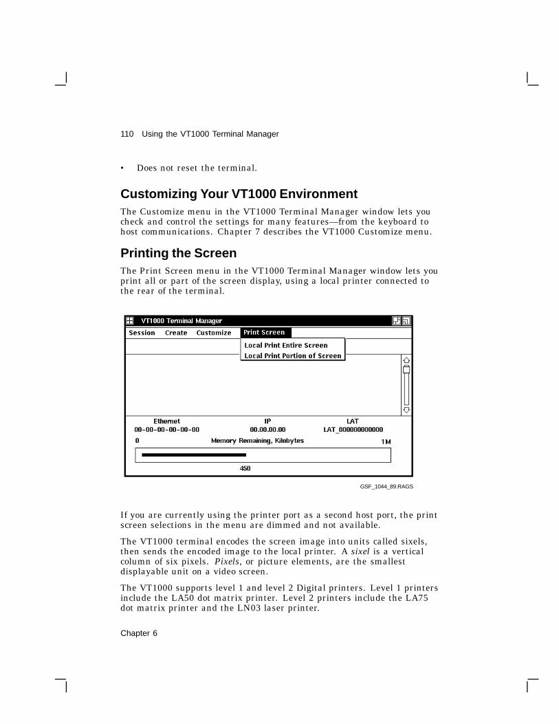
110 Using the VT1000 Terminal Manager
• Does not reset the terminal.
Customizing Your VT1000 EnvironmentThe Customize menu in the VT1000 Terminal Manager window lets youcheck and control the settings for many features—from the keyboard tohost communications. Chapter 7 describes the VT1000 Customize menu.
Printing the ScreenThe Print Screen menu in the VT1000 Terminal Manager window lets youprint all or part of the screen display, using a local printer connected tothe rear of the terminal.
GSF_1044_89.RAGS
If you are currently using the printer port as a second host port, the printscreen selections in the menu are dimmed and not available.
The VT1000 terminal encodes the screen image into units called sixels,then sends the encoded image to the local printer. A sixel is a verticalcolumn of six pixels. Pixels, or picture elements, are the smallestdisplayable unit on a video screen.
The VT1000 supports level 1 and level 2 Digital printers. Level 1 printersinclude the LA50 dot matrix printer. Level 2 printers include the LA75dot matrix printer and the LN03 laser printer.
Chapter 6

Using the VT1000 Terminal Manager 111
To print the complete screen image:Choose the Local Print Entire Screen menu item.
To print a portion of the screen image:
1. Choose the Local Print Portion of Screen menu item. The pointerturns into a cross.
2. Hold down MB1, then drag the pointer across the portion of the screenyou want to print. As you drag the pointer, a rectangle forms aroundthe portion of the screen.
3. Release MB1 to send the image to the printer.
Printer Status
Printer status messages appear in the Messages region of the VT1000Terminal Manager window.
• A Printer Offline message appears if a print request is made but theDTR signal from the printer is not asserted within 2 seconds. Thismessage occurs if the printer is turned off or not connected.
• A Printer Busy message appears if a print request comes in while theprinter is printing another job.
In both cases, the print request is canceled.
Canceling a Print Screen Operation
During large printing jobs, a Print Cancel dialog box appears on thescreen to let you cancel the print operation. Click on the Okay button tocancel the print operation. Printing stops when the printer empties itsinput buffer. The Print Cancel dialog box is not printed.
Chapter 6

7Customizing the VT1000 TerminalManager
7
The Customize menu in the VT1000 Terminal Manager window lets youcheck and control the settings for many features—from the keyboard tohost communications. Initially, the features use factory-default settingsthat work with many host systems. You can make temporary changes forthe current session, or you can save the settings for all future sessions.
To access the terminal’s operating features, you use the Customizemenu in the VT1000 Terminal Manager window. You can look at thecurrent settings of features, change them, and save the new settings. Thefollowing sections describe the Customize menu items.
There are three other ways to customize certain features of your terminal:
• VTE Customize menuWhen you open a video terminal window, you can choose anotherCustomize menu. This menu lets you change certain video terminalwindow features while an application is running. Most of the time,the application handles customization of the video terminal window.Chapter 5 describes how to use the video terminal (VTE) window.
• Host-based control functionsApplications can control many terminal features from the host byusing control functions. Chapter 10 is a summary of VT1000 specificcontrol functions that control the video terminal window.
• Client CustomizeThe X window or DECwindows software package includes its ownCustomize utility, not described here. For more information on theDECwindows Customize utility, see the VMS DECwindows User’sGuide.
112 Chapter 7

Customizing the VT1000 Terminal Manager 113
Displaying the Customize MenuYou pull down the Customize menu from the VT1000 Terminal Manager’smenu bar. The Customize menu looks like this:
GSF_1708_89.RAGS
When you choose a menu item from the menu, the dialog box for that itemappears. Shaded buttons indicate the current settings. You can examinethe settings and change them if necessary. After you make changes in adialog box, you can record your settings or dismiss the dialog box.
When you record your settings, the new settings take effect for thatsession only. To use the new settings for all future sessions, you mustsave the settings in nonvolatile memory. See ‘‘Saving and RecallingSettings’’ in this chapter.
Each dialog box has three push buttons for recording or dismissing newsettings:
Chapter 7

114 Customizing the VT1000 Terminal Manager
Click on . . . To . . .
OK Record new settings and dismiss the dialog box.
Apply Record new settings without dismissing the dialog box.
Cancel Dismiss the dialog box without changing any settings. If youmade any changes without applying them, clicking on theCancel button cancels those changes.
Saving and Recalling SettingsIf you make changes to settings, you can save them for use in all futuresessions. If you do not save your new settings, they are lost when you endyour current session.
If you make temporary changes to settings, you can recall the factory-default settings or the last settings you saved.
To save or recall settings, use the following menu items from theCustomize menu:
Choose . . . To . . .
Use Last Saved Settings Recall the last settings you saved. Choosethis menu item if you want to reset anyfeatures that you changed temporarily, butdid not save.
Use System Defaults Recall the VT1000 factory-default settingsfor the VT1000 Terminal Manager fromread-only memory.
Save Current Settings Save the VT1000 Terminal Managersettings you just changed, so you can usethem in all future sessions.
Some new settings do not take effect until you end your current sessionand begin another one.
Chapter 7

Customizing the VT1000 Terminal Manager 115
Changing Your Keyboard SettingsTo change your keyboard settings, choose the Keyboard . . . menu itemfrom the Customize menu. The Customize Keyboard dialog box appears:
NOTEYou can also customize some keyboard settings for individual VTEwindows. See Chapter 5.
GSF_1046_89.RAGS
From the Customize Keyboard dialog box, you can change any of thefollowing settings:
Bell Volume
A warning bell sounds to alert you to system messages. You can adjustthe bell volume by dragging the arrow in the Percent Volume slider to theright or left. You can also adjust the bell volume by moving the pointer toa location on the slider and clicking MB1. To disable the bell, click on theDisable button.
Default: Enable
Chapter 7

116 Customizing the VT1000 Terminal Manager
Keyclick Volume
Each time you press a keyboard key, the keyboard makes a clicking sound.You can adjust the keyclick volume by dragging the arrow in the PercentVolume slider right or left. You can also adjust the keyclick volume bymoving the pointer to a location on the slider and clicking MB1. Todisable keyclicks, click on the Disable button.
When you use VTE windows, some keys click or autorepeat differentlythan they would when using a DECterm window under DECwindows orwhen using a VT320 video terminal.
Default: Enable
Auto Repeat
When you press a key longer than normal, it repeats until you release it.To disable the auto repeat feature, click on the Disable button. The Helpand Do keys never autorepeat.
When disabled in this dialog box, the auto repeat feature remains offregardless of the setting of the Auto Repeat button in the CustomizeVTE Keyboard dialog box, or host software customized settings (includingremote session managers).
When enabled in this dialog box, the auto repeat feature can be turned onor off in the Customize VTE Keyboard dialog box, or by host software.
Default: Enable
Lock Key State
Normally when you press the lock key on the keyboard, the alphabetickeys send uppercase letters but the number keys do not send their shiftedcharacter.
When you click on the Shift Lock button, all keys send their shiftedcharacter.
Default: Caps Lock
Keyboard Type
The VT1000 keyboard comes in different models for different languagesand dialects. The location of some characters varies depending on thekeyboard model. Make sure the keyboard type matches your keyboardmodel, so the system sends the correct character when you press thecorresponding key.
Chapter 7

Customizing the VT1000 Terminal Manager 117
The default keyboard type is North American. If you have any otherkeyboard model, you must select the correct keyboard type when theterminal is installed.
To find your keyboard model number: Turn the keyboard upsidedown and look for a label that specifies the model number. The modelnumber should be in a format similar to LK401-xx or nn-nnnnn-xx. Usethe xx value to choose your keyboard type from the Keyboard Type scrollbox.
For example, if you have a British keyboard and the model number isLK401-AA, you choose LK401-AA British.
To use this new keyboard type for all future sessions, save the new settingbefore you end the current session. See ‘‘Saving and Recalling Settings’’in this chapter.
When using DECwindows: The DECwindows host session manager hasa similar customize option. Digital recommends that you leave the hostsetting at System Default to avoid having the host session manager andlocal terminal manager compete to set the keyboard. There are subtledifferences between the LK401 keyboard layouts supported by the VT1000and the LK201 keyboard layouts supported by DECwindows.
Default: North American
Keyboard Mode
You can specify whether you want your keyboard to act as a typewriter(TW) or data processing (DP) keyboard. This setting affects keys withthree or more characters. If you choose a data processing keyboard, thesekeys send the characters on the right half of their keycaps. If you choosea typewriter keyboard, these keys send the characters on the left half oftheir keycaps.
For the following keyboard types, the typewriter and data processingsettings are identical:
• North American and Dutch
• When using 8-bit multinational characters: British, German, andPortuguese
Default: Typewriter
Chapter 7

118 Customizing the VT1000 Terminal Manager
Choosing the Display LanguageCustomize Language
The VT1000 Terminal Manager supports three languages: English,French, and German. After you apply your selection, the terminaldisplays text in the language you selected. To change your displaylanguage setting, choose the Language . . . menu item from the Customizemenu. The Customize Language dialog box appears:
GSF_1047_89.RAGS
To select a language, click on the appropriate button.
The selected language only applies to the VT1000 terminal locally. Theremay be times when your host application has a different setting than yourterminal.
Default: English
Chapter 7

Customizing the VT1000 Terminal Manager 119
Changing Your Pointer and Mouse SettingsYou can change the shape and color of the pointer, as well as certainmouse features. To change your mouse and pointer settings, choose thePointer . . . menu item from the VT1000 Terminal Manager’s Customizemenu. The Customize Pointer dialog box on your monochrome VT1000terminal looks like this:
From the Customize Pointer dialog box, you can change any of thefollowing settings:
Button Arrangement
The default mouse button arrangement is natural for a right-handeduser—MB1 on the left of the mouse and MB3 on the right. If you areleft-handed, you can click on the Left Handed button. This makes MB1the right mouse button and MB3 the left mouse button. MB2 is alwaysthe middle button.
Default: Right Handed
Chapter 7
120 Customizing the VT1000 Terminal Manager
Pointer Color
The pointer consists of an outline and filled center. On your monochromeVT1000 terminal, the pointer’s filled area is normally white with a blackoutline. To reverse the fill and outline colors, click on the Black button.To see your changes, click on the Apply button or OK button in the dialogbox.
Default: White
Pointer Shape
To change the pointer shape, scroll through the list of shapes and selectthe one you want.
Default: Upper Left Arrow
Mouse Double Click Timeout
Video terminal (VTE) windows can tell two single clicks from a doubleclick, based on the speed at which buttons are clicked. To change the timeallowed for making the second click in a double-click sequence, drag thearrow in the slider to the right or left, or move the pointer to a location onthe slider and click MB1.
Changing Your Print Screen SettingsThe terminal’s Customize Print Screen dialog box lets you control certainprinting features. To view the print screen settings, choose the PrintScreen . . . menu item from the VT1000 Terminal Manager’s Customizemenu. The Customize Print Screen dialog box appears:
Chapter 7

Customizing the VT1000 Terminal Manager 121
From the Customize Print Screen dialog box, you can change the followingsettings:
Pixel Aspect Ratio
You can select the pixel aspect ratio to match the dot density of theprinter you are using. A pixel aspect ratio of 1 to 1 is appropriate formost printers.
• For level 2 printers such as the LA75 or LN03, use a pixel aspect ratioof 1 to 1.
• For level 1 printers such as the LA50, use a pixel aspect ratioof 2 to 1.
Default: 1 to 1
Rotate/Scale Picture
For wide screen images, you can have the terminal rotate and scale theimage so it fits on the printed page. Click on the Rotate/Scale Picturebutton to automatically rotate and scale an image sent to the printer.
Default: off
Chapter 7

122 Customizing the VT1000 Terminal Manager
Ribbon or Toner Saver
Normally, screen snapshots are printed as you would expect—the image isdark, and the background is light. If you have an image that fills most ofthe screen, this may consume a great deal of printer ribbon or toner. Toreverse the dark and light portions of the printed output and save ribbonor toner, click on the Negative Image button.
Default: Positive Image
Print FF Mode
The VT1000 terminal can send a form feed (FF) character to the printerport at the end of a print screen operation. If you want to send a formfeed, click on the Form Feed button.
Default: No Form Feed
Changing Your Security SettingsTo prevent unauthorized connections to your terminal, you can enter alist of authorized users that can connect to your terminal. You can alsolock your customize dialog boxes to prevent accidental and unauthorizedchanges to your customized settings.
Choose the Security . . . menu item from the VT1000 Terminal Manager’sCustomize menu to display the Customize Security dialog box:
Chapter 7

Customizing the VT1000 Terminal Manager 123
From the Customize Security dialog box, you can change any of thefollowing settings:
LAT Connections and TCP/IP Connections
You can choose which hosts can connect to your VT1000 terminal. Onlyauthorized hosts can make connections to the terminal. To allow all hosts,no hosts, or only those authorized to connect to the terminal, click on theappropriate button.
Chapter 7

124 Customizing the VT1000 Terminal Manager
All This is the default setting. Any system on the Ethernet can establishan X connection with your terminal. Use this setting if you are part ofa small group running interactive applications that require sharing ofinformation in realtime.
Authorized Only When you choose this setting, only the systems and usersentered in the Authorized Users scroll box can establish X connectionswith your terminal. This setting requires that you authorize your ownaccount in addition to any others that need access to your display.
None This setting prevents any X connection to your terminal, regardlessof source. This is useful if you use the VT1000 as multiple VT320terminals in a confidential environment, and do not want any otheruser’s applications to display on your screen or to request data from yourscreen.
If you choose the None setting, any connection request from the LAT XSession menu item in the Create menu will fail.
Default: All
Add an Authorized User
You can maintain a list of four authorized users. These users haveimmediate access to your VT1000 terminal. The VT1000 stores the nodenames, usernames, and transports (LAT or TCP/IP) of these users, innonvolatile memory.
To add an authorized user to the Authorized Users box:
1. Enter a node name or IP address into the Node text entry field, thenpress the Return key.
Examples: DELTAor 123.45.67.89
2. Enter a username into the Username text entry field, then pressReturn . You can use the asterisk (*) wildcard character to specify allusers.
Examples: Smith or *
For TCP/IP: Use the asterisk (*) wildcard character, to specify allusers. The TCP/IP protocol does not track usernames, so you cannotauthorize individual users when accepting TCP/IP connections. If thenode is an approved IP address, the VT1000 accepts any connectionsfrom that node.
3. Enter a transport (communication protocol) into the Transport textentry field, then press Return .
Chapter 7

Customizing the VT1000 Terminal Manager 125
Examples: LAT or TCP.
The newly authorized user appears in the Authorized Users box.
Remove an Authorized User
To remove an authorized user from the Authorized Users box:
1. In the Authorized Users box, click on the username of the user youwant to remove.
2. Click on the Remove button.
Accept Connections When Idle
Your VT1000 terminal has the ability to accept connections fromauthorized host systems when idle. The terminal is idle from the time itis turned on and completes it power-up tests until a menu item is chosenin the VT1000 Terminal Manager.
This feature lets your terminal act as a slave display device requiringno active intervention. To enable this feature, click on the AcceptConnections When Idle button. This allows the terminal to accept Xwindow and DECwindows connections when idle.
NOTEFor desktop units where people frequently log in, acceptingconnections when idle may be a security risk. Digital recommendsthat you leave this feature off for desktop units.
Default: off—reject connections when idle
Locking Your Customize Dialog BoxesYou can lock your VTE or VT1000 Terminal Manager customize dialogboxes to prevent accidental and unauthorized changes to your customizedsettings. You can also choose whether or not to make a locked customizedialog box visible. By default, all customized dialog boxes are unlocked.
When you lock dialog boxes, the Customize Security Password dialog boxappears. See ‘‘Activating Customize Password Security ’’ in this chapter.
Chapter 7

126 Customizing the VT1000 Terminal Manager
Lock Customize Security
You can lock the Terminal Manager’s Customize Security dialog box toprevent unauthorized users from adding more users to the AuthorizedUsers list. Click on the Lock Customize Security toggle button, then clickon the OK button or Apply button. The Customize Security Passworddialog box appears.
Default: Unlocked
Lock Terminal Manager Customize
You can lock all customize dialog boxes in the VT1000 TerminalManager Customize menu, to prevent unauthorized users from changingcustomized settings. Click on the Lock Terminal Manager Customizetoggle button, then click on the OK button or Apply button. TheCustomize Security Password dialog box appears.
Default: Unlocked
Lock VTE Customize
You can lock all customize dialog boxes in the VTE Customize menu, toprevent unauthorized users from changing customized settings. Click onthe Lock VTE Customize toggle button, then click on the OK button orApply button. The Customize Security Password dialog box appears.
Default: Unlocked
Locked Screens Visible
You can choose whether or not to make locked customize dialog boxesvisible. To change the current setting, click on the Locked Screen Visibletoggle button, then click on the OK or Apply button.
Default: off—locked screens not visible
If a customize dialog box is locked and visible: When you choose thecustomize dialog box from the Customize menu, the dialog box appearsbut you cannot change any settings. The one exception is the CustomizeSecurity dialog box. It always requires a password if it is locked.
Chapter 7

Customizing the VT1000 Terminal Manager 127
If a customize dialog box is locked and not visible: When you choose thatcustomize dialog box from the Customize menu, a Password promptappears. You must enter the correct security password before you candisplay the dialog box.
To display a locked customize dialog box that is not visible: Enter yoursecurity password and click on the OK button. If you enter the correctpassword, the selected customize dialog box is displayed and you canmake changes to the settings. If you enter an incorrect password, theterminal displays a User authorization failure box.
If you select . . . The terminal . . .OK Verifies that your password is correct.
Clear Clears the password field.
Cancel Dismisses the password prompt.
If you forget the password, contact Digital Customer Services to performa secure reset. A secure reset erases all of the terminal’s nonvolatilememory (except the secure reset count) and resets the terminal’s operatingfeatures to their factory-default settings.
Chapter 7

128 Customizing the VT1000 Terminal Manager
Activating Customize Password SecurityTo prevent accidental or unauthorized changes to your VTE or VT1000Terminal Manager customize dialog boxes, use the Lock . . . togglebuttons in the Customize Security dialog box. When you turn on one ofthese toggle buttons and click on the Apply or OK button, the CustomizeSecurity Password dialog box appears. From the Customize SecurityPassword dialog box, you can enter a new customize security password oruse the current password.
From the Customize Security Password dialog box, you can choose thefollowing items:
Enter Password
To enter or change the security password, type a new password (up to 127characters) into the Enter Password text entry field. The terminal doesnot display the characters you enter, and the cursor does not move. Thenclick on the Verify Password text entry field.
Verify Password
To make sure the password you entered is correct, reenter the passwordinto the Verify Password text entry field. The terminal does not displaythe characters you enter, and the cursor does not move. After you enterthe password, click on the OK button to activate the password and dismissthe dialog box.
If you enter the incorrect password, the terminal displays a PasswordVerification Error box.
To save the password for future sessions, use the Save Current Settingsmenu item in the VT1000 Terminal Manager’s Customize menu.
Chapter 7

Customizing the VT1000 Terminal Manager 129
Use Previous Password
If you already entered a password in this session (or saved a password ina previous session), you can click on the Use Previous Password button toquickly dismiss this dialog box and activate your customize password.
OK, Clear, and Cancel
If you select . . . The terminal . . .OK Activates the password.
Clear Clears both password text entry fields and movesthe cursor to the Enter Password text field.
Cancel Dismisses the Customize Security Password dialogbox and returns to the Customize Security dialogbox without activating password security.
Changing Your Window SettingsYou can change the look of your terminal’s window display. For example,you can change the background pattern, window color, and screen color.To change your window settings, choose the Window . . . menu itemfrom the VT1000 Terminal Manager’s Customize menu. The CustomizeWindow dialog box looks like this:
Chapter 7

130 Customizing the VT1000 Terminal Manager
GSF_1051_89.RAGS
Some changes take effect when you click on the Apply button or OKbutton in the Customize Window dialog box. Others take effect in yournext session. See the individual features for details.
From the Customize Window dialog box, you can change any of thefollowing settings:
Screen Saver
The Screen Saver extends the life of your monitor by shutting off itsdisplay after a specified time. Normally, the terminal shuts off its displayafter 10 minutes of keyboard or mouse inactivity. You can vary the timebefore the screen goes blank, from 1 to 60 minutes.
• To vary the time the screen saver waits before shutting down thedisplay, drag the arrow in the slider to the right of left, or move thepointer to a spot on the slider and click MB1.
• To keep the display on indefinitely, click on the Disable button.
• Click on the Apply button or OK button to apply your change.
Chapter 7

Customizing the VT1000 Terminal Manager 131
You can check if the screen saver is on by looking at the keyboardindicator lights. The lights blink in a regular pattern when the screensaver is on.
Default: 10 minutes
Allow Remote Window Manager
You can choose whether or not a host-based window manager can takeover windowing operations on the screen. The VT1000’s local windowmanager provides you with quicker response time and overall higherperformance. However, a host-based window manager may offer morefeatures. To let the host control windowing operations, click on the AllowRemote Window Manager button.
Default: off
Screen Background Pattern
Normally, the screen background pattern is a tight, gray crossweave. Tochange the background pattern, click on a pattern in the pattern palette.The pattern you select appears in the pattern viewer. Click on the Applybutton or OK button to see your selection in effect.
You can also create a solid background by clicking on one of twobackground pattern buttons next to the Default button.
• Click on the left button to create a solid background in the screenforeground color. For example, if the Screen Color is Black on Whiteon your monochrome system, click on the left button in the ScreenBackground Pattern to see a solid black background.
• Click on the middle button to create a solid background in the screenbackground color.
Default: Gray crossweave
Window Manager Icon Style
Normally, the icons stored in the Icon Box are small. Click on the Largebutton to change the size of the icons. If you save your changes, the IconBox will contain large icons when you start your next session.
Default: Small
Chapter 7

132 Customizing the VT1000 Terminal Manager
Screen Color
The screen pattern, when set to anything other than the default pattern,consists of a screen foreground (the filled area in the pattern) and a screenbackground (the pattern’s outline).
On your monochrome VT1000 terminal, the screen color is normally black.Click on the White on Black option button to reverse the fill and outlinecolors.
To see your new setting in effect, click on the Apply button or OK button.
Default: Black on White
Window Color
The Window Color setting controls the color of text or graphics in awindow. On your monochrome VT1000 terminal, the window color isnormally black. Click on the White On Black button to change thewindow color to white.
If you save your changes by clicking on the Apply button or OK button,your new setting takes effect when you start your next session.
Default: Black on White
Controlling the Display of MessagesYou can choose whether or not to have the terminal display certainmessages, such as connection requests. You can choose settings thatsuit your preference or the needs of your application software. Messagesappear in the Messages region of the VT1000 Terminal Manager Window.Choose the Terminal Manager... menu item from the VT1000 TerminalManager’s Customize menu. The Customize Terminal Manager dialog boxlooks like this:
Chapter 7

Customizing the VT1000 Terminal Manager 133
GSF_1368_89.RAGS
From the Customize Terminal Manager dialog box, you can change any ofthe following settings:
Confirm Quit Session
When you quit a session from the Session menu, the terminal normallyasks for confirmation. You can turn this feature on or off by clicking onthe Confirm Quit Session toggle button. If you turn this feature off, theterminal ends the current session immediately after you choose Quit fromthe Session menu.
Default: enabled
Display Connection Requests
The terminal can display connection requests in the Messages region.You can turn this feature on or off by clicking on the Display ConnectionRequests toggle button.
Default: enabled
Chapter 7

134 Customizing the VT1000 Terminal Manager
Display Rejected Connection Requests
Normally, the terminal does not display rejected connection requests.You can choose to have the terminal display the rejection messages inthe Messages region. To turn this feature on or off, click on the DisplayRejected Connection Requests toggle button.
Default: disabled
Display Diagnostics Messages
Diagnostic messages indicate any problem with the network server orterminal. Normally, the terminal does not display these messages. Youcan choose to have the terminal display the diagnostic messages in theMessages region. To turn this feature on or off, click on the DisplayDiagnostic Messages toggle button.
Default: disabled
Messages Region
You can scroll through text in the Messages region. The Scroll LinesSaved slider lets you specify how many lines scrolled out of the region tosave. Any extra lines are lost.
This feature does not affect the size of the Messages region. The widthof the Messages region can change if you change the VT1000 TerminalManager window size.
Header Text
You can specify the text of the header the terminal uses for the Messagesregion. Just click on the Header Text field, then enter your header. Themessage header can have up to 30 characters.
Default: Messages
Changing Your Host Port or Printer Port SettingsYou can specify the communication settings of the terminal’s serial hostand printer ports to make them compatible with your host system. Thedefault settings work with most Digital systems. Make sure the settingsyou use match your host system.
Chapter 7

Customizing the VT1000 Terminal Manager 135
The host port is for connecting to a host system. The printer port is forconnecting either to a local printer or a second host. Each port uses aDEC-423, 6-pin connector.
NOTEYou cannot use X windows or DECwindows over the hostor printer port. These ports are for traditional terminalcommunication with host systems. You must use the Ethernetconnector to use X windows or DECwindows.
The Customize Host Port and Customize Printer Port dialog boxes areidentical, except for a few extra buttons in the Customize Printer Portdialog box.
To change the host port settings, choose the Host Port... menu item fromthe VT1000 Terminal Manager’s Customize menu. The Customize HostPort dialog box looks like this:
Chapter 7

136 Customizing the VT1000 Terminal Manager
To change the printer port settings, choose the Printer Port... menu itemfrom the VT1000 Terminal Manager’s Customize menu. The CustomizePrinter Port dialog box looks like this:
From the Customize Host or Printer Port dialog box, you can change anyof the following settings:
Transmit
You can select the speed the terminal uses to send data to the host systemor printer. Normally, the terminal’s host port uses a speed of 9600 baud,and the printer port uses a speed of 4800 baud. These settings work withmost Digital systems. To select another speed, click on the button next tothe speed you want.
The VT1000 terminal does not support speeds lower than 300 baud.
Chapter 7

Customizing the VT1000 Terminal Manager 137
Default: 9600 for host port, 4800 for printer port
Receive
You can choose the speed the terminal uses to receive data from thehost system or printer. Normally, the terminal’s receive speed matchesits transmit speed (rx = tx). However, the terminal can transmit at onespeed and receive at another. To choose another speed, click on the buttonnext to the speed you want. Make sure you choose a receive speed thatmatches your host’s or printer’s transmit speed.
Default: rx = tx
Character Format
You can choose the word size and number of parity bits used tocommunicate with the host system or printer. The terminal uses a defaultword size of 8 bits and no parity. This setting works with most of today’scomputer systems.
Default: 8-bit, No Parity
Stop Bits
You can choose the number of stop bits used in the character format.Digital recommends using one stop bit for most applications. To select twostop bits, click on the Two button.
Default: One
XOFF At
You can choose how many characters the terminal stores in its receivebuffer before sending the host or printer an XOFF signal to stop sendingdata. Normally, the terminal sends XOFF to the host when the inputbuffer contains 64 characters. See Appendix C for details. To choose 128characters or no XOFF, click on the appropriate button.
Default: 64
Use as (in Customize Printer Port dialog box only)
Normally, the printer port acts as a printer port. When you use thissetting, you can connect a local printer to the terminal for print screenoperations. You can choose one of four functions for the printer port:
Chapter 7

138 Customizing the VT1000 Terminal Manager
Choose . . . To . . .
Host Port Use the printer port to connect the terminal to a secondhost system.
Printer Port Use the printer port to connect a local printer.
2-Way Printer Port Let the printer send control information to the host.
Diagnostics Port Unsupported.
To choose the Host Port or 2-Way Printer Port settings, click on theappropriate button.
Default: Printer Port
Changing Your LAT SettingsVMS systems use the local area transport (LAT) protocol to connect to theterminal. You can control the list of hosts and services that can connect toyour terminal. The terminal uses LAT group codes to identify hosts andservices. The terminal can store 256 group codes (0–255). Your systemmanager can also adjust the performance of LAT connections.
To change LAT settings and adjust performance, choose the LAT...menu item from the VT1000 Terminal Manager’s Customize menu. TheCustomize LAT dialog box looks like this:
Chapter 7

Customizing the VT1000 Terminal Manager 139
From the Customize LAT dialog box, you can change any of the followingsettings:
Group Codes
The Group Codes scroll box lets you maintain a list of the groups of hostsor services that you want to access. The LAT protocol uses group codesto limit the number of network services that a device must identify andcommunicate with. On a large local area network, requiring the terminalto communicate with all the available services may overflow the serviceslist in the LAT Terminal Window Service Select or LAT X Session ServiceSelect dialog boxes.
Chapter 7

140 Customizing the VT1000 Terminal Manager
By default, all LAT devices are set to use group code 0 so they can allcommunicate. In a large network, the network manager can chooseto change the group code for some services. For example, the servicesassociated with an engineering group might be in group 1, while themanufacturing group’s services are in group 2.
Ask your system manager for your service’s group code. If the code is 0,you can use the terminal immediately. If the code is another value, youcan add it to the list.
Default: Group Code 0
To add a new group code:
1. Use your keyboard to enter the group code into the text entry field.
2. Click on the Add button. The new group code appears in the GroupCodes scroll box.
3. Repeat this procedure for each group code you want to add.
To remove a group code from the list:
1. In the scroll box, click on the group code you want to remove.
2. Click on the Remove button.
To enable all the group codes on your network:
Click on the Add All button to enable the terminal to use all group codeson your network. Remember that the terminal can store a limit of 256group codes. You should only use this feature if your network has a lownumber of group codes.
To remove all the group codes from the scroll box:
Click on the Remove All button.
LAT Slide Bars (For System Managers)
You can fine tune the characteristics of your LAT environment byadjusting the four slide bars provided in the Customize LAT dialog box.
See your system manager for the optimal settings of these slide bars.They directly affect the performance of your local area network andshould only be adjusted by system management personnel. The slidebars are not intended to be randomly set according to the preference ofindividual users. Poor adjustments can produce poor network and VT1000terminal performance.
Chapter 7

Customizing the VT1000 Terminal Manager 141
There are four slide bars:
LAT VTE Circuit TimerYou set the LAT VTE Circuit Timer to tune the network for the bestresponse time and network performance when running video terminal(VTE) windows. The optimum setting depends on the number of userson the local area network and the typical network traffic conditions.The normal setting of 80 milliseconds works well with most Digitalsystems.
Default: 80 milliseconds
LAT X Circuit TimerYou set the LAT X Circuit Timer to tune the network for the bestresponse time and network performance when running an X windowor DECwindows session. The optimum setting depends on the numberof users on the local area network and the typical network trafficconditions. The normal setting of 30 milliseconds works well withmost Digital systems.
Default: 30 milliseconds
Retransmit LimitTo make a LAT connection to a host system, the terminal sends outa request-to-connect message then waits for an acknowledgement. Ifthe host does not acknowledge the request, the terminal resends themessage a specified number of times.
The Retransmit Limit tells the terminal how many times to resendthe message. If the terminal does not receive an acknowledgementafter sending the message the specified number of times, the terminalstops requesting a connection and indicates it could not connect tothat host.
Normally, the terminal resends the message eight times before it stopstrying to connect. This setting works well with most Digital systems.
Default: 8 times
Keep Alive TimerWhen the terminal is inactive, it sends certain LAT messages outon the network every few seconds to keep the LAT connection alive.Normally, the terminal sends messages out every 20 seconds. Thissetting works well with most Digital systems.
Default: 20 seconds
Chapter 7

142 Customizing the VT1000 Terminal Manager
Changing Your TCP/IP Settings (ULTRIX and UNIXSystems)ULTRIX and UNIX systems use the TCP/IP protocol to connect to theterminal. From the Customize TCP/IP dialog box, you can enter theterminal’s IP address and subnet mask. You can also open dialog boxesfor changing the name server and network routing tables.
Choose the TCP/IP... menu item from the VT1000 Terminal Manager’sCustomize menu. The Customize TCP/IP dialog box looks like this:
From the Customize TCP/IP dialog box, you can change any of thefollowing settings:
Determine IP Address
Clicking on this button makes the terminal determine its IP address,using the UDP/IP BOOTP protocol. BOOTP is an Internet protocol thatdetermines an IP address.
Chapter 7

Customizing the VT1000 Terminal Manager 143
After you click on the Determine IP Address button, a few messagesappear in the Messages region of the VT1000 Terminal Manager window,along with the IP address of the terminal. The next time you enter theCustomize TCP/IP dialog box, the terminal’s IP address appears in theVT1000 IP Address (manual): text entry field.
NOTEThe system manager of a host system running the BOOTP daemonmust configure your terminal’s hardware and IP address into theBOOTP daemon’s configuration file.
TCP/IP Name Server...
Clicking on this button displays the Customize TCP/IP Name Serverdialog box. See ‘‘Changing Your TCP/IP Name Server Settings’’ in thischapter.
TCP/IP Routing Tables...
Clicking on this button displays the Customize TCP/IP Routing Tablesdialog box. See ‘‘Changing Your TCP/IP Routing Table Settings’’ in thischapter.
VT1000 IP Address (manual):
You can manually enter an IP address for your terminal. See your systemmanager for an address to use. To enter the address, click on the VT1000IP Address (manual): text entry field. After you enter an address, clickon the OK button to save the address (for this session only) and dismissthe dialog box.
IP Subnet Mask:
You can manually enter an IP subnet mask for your terminal. An IPsubnet mask acts as a filter for your TCP/IP network. Using the subnetmask makes the terminal ignore certain traffic on the network.
See your system manager for a subnet mask to use. To enter an IP subnetmask, click on the IP Subnet Mask: text entry field. After you enter theIP subnet mask, click on the OK button to save the mask (for this sessiononly) and dismiss the dialog box.
Chapter 7
144 Customizing the VT1000 Terminal Manager
Changing Your TCP/IP Name Server SettingsIf your system has name servers, you can specify host names instead ofaddresses in the TELNET Terminal Window Host Select dialog box. Aname server resolves destination names into network addresses.
You can specify a primary and secondary Berkeley Internet Name Domain(BIND) name server. You can also determine and change the terminal’sdomain name. See your system manager for your name server’s IPaddress.
Choose the TCP/IP... menu item from the VT1000 Terminal Manager’sCustomize menu. The Customize TCP/IP dialog box appears. Click onthe TCP/IP Name Server... button. If you have not entered an IP addressfor the terminal in this dialog box, the TCP/IP Name Server... button isdimmed (not selectable). The Customize TCP/IP Name Server dialog boxlooks like this:
From the Customize TCP/IP Name Server dialog box, you can change anyof the following settings:
Chapter 7

Customizing the VT1000 Terminal Manager 145
Primary Name Server
The terminal first attempts to use the primary name server to resolvenames entered into fields requiring a host name or IP address.
To enter or change the primary name server, click on the text entry fieldand enter the primary name server’s IP address.
Secondary Name Server
If the terminal cannot resolve a host name or IP address with the primaryname server, the terminal queries the secondary name server.
To enter or change the secondary name server, click on the text entry fieldand enter the secondary name server’s IP address.
Determine Domain Name
When you click on this button, the terminal tries to determine its owndomain name. You must have previously entered a primary or secondaryname server and clicked on the Apply button. Name resolution is notpossible without a valid domain name. After determining its domainname, the terminal displays the name in the Domain Name text entryfield.
Domain Name
To enter or change the domain name, click on the text entry field andenter the domain name. Example: MYORG.MYCOMP.COM.
Changing Your TCP/IP Routing Table SettingsFrom the TCP/IP Routing Tables dialog box, you can update the networkrouting tables. If you have not entered an IP address, the TCP/IP RoutingTables... button is dimmed (not selectable).
Choose the TCP/IP... menu item from the VT1000 Terminal Manager’sCustomize menu. Click on the TCP/IP Routing Tables... button. TheCustomize TCP/IP Routing Tables dialog box looks like this:
Chapter 7

146 Customizing the VT1000 Terminal Manager
From the Customize TCP/IP Routing Tables dialog box, you can add orremove a temporary or preferred route. You can save preferred routes forfuture sessions by using the Save Current Settings menu item from theCustomize menu. The terminal does not save temporary routes for futuresessions.
Although the Temporary Routes and Preferred Routes boxes only displaythe route destination, both a destination and a gateway are stored foreach entry.
Temporary and Preferred Routes
To add a route:
1. Specify whether the route applies to either a host or a network, byclicking on the Host or Network button. If you click on the Autobutton, the terminal tries to determine if the route is for a host or anetwork.
Chapter 7

Customizing the VT1000 Terminal Manager 147
2. Enter the route’s data into the Destination and Gateway text entryfields.
3. Click on the Add box beside the Temporary or Preferred Routes box.You can save preferred routes for future sessions by using the SaveCurrent Settings menu item in the VT1000 Terminal Manager’sCustomize menu.
To view or change stored data for a route:
Click on the route’s destination displayed in the Temporary Routes orPreferred Routes scroll box. The terminal displays the route’s destinationand gateway in their text entry fields.
To remove a route:
1. Click on the route’s destination displayed in the Temporary Routes orPreferred Routes scroll box.
2. Click on the Remove button next to the scroll box.
Changing Your Font Path SettingsA font is a set of characters in a particular type style. The terminaldisplays characters from a selected font. The terminal has its own set ofcharacter fonts, but for some applications you may need to use alternatefonts available on your host system. To find a font file on the host, theterminal needs a font path.
You need to enter a font path before using X window sessions andapplications, because the terminal’s ROM fonts do not contain all therequired fonts. The terminal will allow you to create an X session withouta font path, but you will have to quit and restart the terminal to set thefont path.
After you make a connection that uses the font path, you cannot changethe font path without quitting from the session. The Font Path... menuitem is dimmed and not selectable.
You can specify a font path by choosing the Font Path... menu item fromthe VT1000 Terminal Manager’s Customize menu. The Customize FontPath dialog box looks like this:
Chapter 7

148 Customizing the VT1000 Terminal Manager
From the Customize Font Path dialog box, you can change any of thefollowing settings:
Font Path Selection
The Font Path Selection determines which font path is active. If yourterminal communicates over the LAT protocol, click on the LAT FontPath button. If your terminal communicates over the TCP/IP or TELNETprotocol, click on the TFTP Font Path button.
LAT Font Path
Before you enter a font path, the terminal uses only its own fonts storedin ROM. The first entry in the LAT Font Path field is ROM, indicatingthe terminal is using its own fonts. Always leave the ROMentry at thebeginning of the field.
If you enter a font path pointing to a node on your system, the terminaluses the font files on that node. You can enter a font path name of up to30 characters.
To enter a LAT font path:
1. Click on the LAT Font Path button under the Font Path Selectiontitle.
Chapter 7

Customizing the VT1000 Terminal Manager 149
2. The LAT Font Path text entry field already has the word ROMentered.Enter a comma (,) followed by a font host name and two colons.
Example:
ROM,ALPHA::
ALPHA:: is the font server name. It can be a node name or a clustername. You must leave ROM at the beginning of the line, followed by acomma, the font server name, and the two colons.
No further specification is needed, unless the system manager moves thefonts out of the default directory created when the windows software andfonts were installed on the system.
Setting a LAT font path may take several minutes. The terminal mustwait for the font service to become known. Each time you power up theterminal or restart it by choosing Quit, the terminal immediately tries toset the font path that was saved. If the font service is not immediatelyknown, the terminal tries every 30 seconds to set the font path, for up to2.5 minutes. The LAT default multicast interval is 2 minutes.
When the font service is known, the process of setting the path starts onthe next retry. If the font setting does not restart after 2.5 minutes, or ifthe service becomes known between retries, you can restart it by clickingon Okay in the Customize Font Path dialog box.
When the font service is known, setting the LAT set font path takes lessthan a minute. The message Font Path Succeeded is displayed in theVT1000 Terminal Manager window’s Messages region, along with a reportof the number of fonts found.
TFTP Font Path
Before you enter a font path, the terminal uses only its own fonts storedin ROM. The first entry in the TFTP Font Path field is ROM, indicatingthe terminal is using its own fonts. Always leave the ROMentry at thebeginning of the field.
If you enter a font path pointing to a node on your system, the terminaluses the font files on that node. You can enter a font path name of up to30 characters.
To enter a TFTP font path:
1. Click on the TFTP Font Path button under the Font Path Selectiontitle.
2. Click on the TFTP Font Path text entry field.
Chapter 7

150 Customizing the VT1000 Terminal Manager
3. The word ROMis already entered in the TFTP Font Path text entryfield. Use your keyboard to enter a comma (,) followed by a font hostIP address. Use the syntax IP_address::path_name. See your systemmanager if you need help.
Example:
ROM,123.45.67.89:/vt1000/100dpi/fonts.dir
The exact format depends on how your system manager defines the fontpath. See Appendix D for details.
Each time you power up the terminal or reset it by using a quit function,the terminal tries to set a font path. The terminal must wait for the fontservice to become known before it begins to set the path. While settingthe path, the terminal displays a clock cursor. All other terminal activityhalts until the path is set.
Tips on Setting Font Paths
The time needed to set a font path depends on how many fonts are in thefont path. To lessen the time to set a font path:
• Point only to the font files that support the resolution of your monitor.
• In a mixed LAT and TCP/IP environment, use a LAT system for thefont service.
• In a non-DECwindows environment, point only to the files needed foryour application.
System managers should see Appendix D for instructions on creatingfiles and configuring systems for font paths. Note that the font path inthe previous example is based on a restricted TFTP setup in the systemconfiguration file.
Chapter 7

8The Keyboard
8
This chapter describes the basic function of each keyboard key andindicator. Chapter 9 describes how to type additional characters notshown on the keys.
LK401 KeyboardThe VT1000 terminal uses Digital’s LK401 keyboard. The LK401keyboard comes in many versions for use with different languages anddialects. The only physical difference between these keyboards are thelegends on the keys.
The figures in this chapter show the North American/United Kingdomkeyboard, unless otherwise noted.
Keyboard Dialect
The VT1000 is initially set to work with the North American/UnitedKingdom keyboard. If you have a keyboard for a different language oryou want to use the British dialect, you must change the KeyboardType setting in the Customize Keyboard dialog box. See ‘‘Changing YourKeyboard Settings’’ in Chapter 7.
Layout
The LK401 keyboard has four groups of keys and two visual indicators.The keys are grouped by function.
Main keypadEditing keypadNumeric keypadTop-row function keys
Chapter 8 151
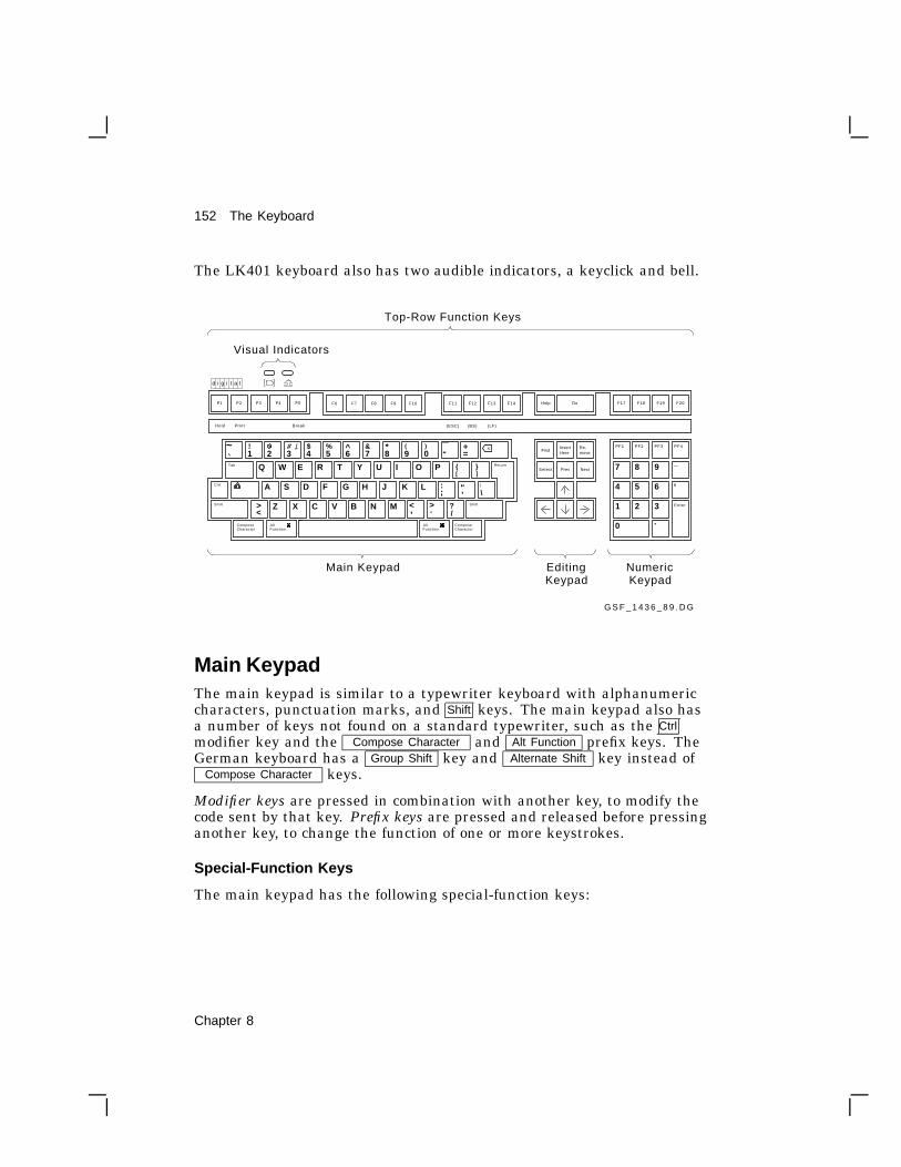
152 The Keyboard
The LK401 keyboard also has two audible indicators, a keyclick and bell.
G S F _ 1 4 3 6 _ 8 9 . D G
Top-Row Function Keys
Visual Indicators
Main Keypad EditingKeypad
NumericKeypad
X
Z X C V B N
A S D F G H J K L
I O PT Y UW E R
M
Q
1 2 3 4 5 6 7 8 9 0! # $ % ^ & * ( )a~
><
Tab
Ctrl
Return
ShiftShift ?/.,
:; "
’ \
]
_- +
=
] Prev Next
Re-move
InsertHere
Find
Select
PF1 PF2 PF3 PF4
Enter
54
7 8 9 _
,6
321
0 .
Hold Print Break F6 F7 F8 F9 F10 F14 F17 F18 F19 F20(ESC) (BS) (LF)
Help DoF1 F2 F3 F4 F5 F6 F7 F8 F9 F10 F17 F18 F19 F20F14F13F12F11
AltFunction
ComposeCharacter
AltFunction
ComposeCharacter
d i ig t a l
><
Main KeypadThe main keypad is similar to a typewriter keyboard with alphanumericcharacters, punctuation marks, and Shift keys. The main keypad also hasa number of keys not found on a standard typewriter, such as the Ctrlmodifier key and the Compose Character and Alt Function prefix keys. TheGerman keyboard has a Group Shift key and Alternate Shift key instead of
Compose Character keys.
Modifier keys are pressed in combination with another key, to modify thecode sent by that key. Prefix keys are pressed and released before pressinganother key, to change the function of one or more keystrokes.
Special-Function Keys
The main keypad has the following special-function keys:
Chapter 8

The Keyboard 153
Tab Pressing Tab in a VTE sends a horizontal tab, whichnormally moves the cursor to the next tab stop.Applications can change tab stops. In the VT1000Terminal Manager screens and in some DECwindowsmenus, Tab moves the cursor to the next text entry field.
Ctrl Holding down Ctrl and pressing another key sends acontrol code to the host.
For example, Ctrl Z means to hold down Ctrl and pressthe Z key.
Shift There are left and right Shift keys. Holding down Shiftand pressing a standard key sends the shifted (top)character on the key.
Holding down Shift and pressing a special-function keystarts a predefined control function. For example, ShiftF2 (Print) means to hold down Shift while pressing the F2(Print) key.
Pressing the lock key down puts the keyboard in capslock mode or shift lock mode. You can set the mode fromthe Customize Keyboard dialog box (Chapter 7). Thedefault setting is Caps Lock.
• In caps lock mode, the alphabetic keys send theiruppercase or shifted character when pressed alone.You can use a Shift key to send the shifted characteron other keys. You turn caps lock mode on and off bypressing and releasing the lock key.
• In shift lock mode, all keys on the main keypad sendtheir shifted character. You can turn shift lock modeon or off by pressing the Lock key.
When the lock key is down, the lock indicator on thekeyboard turns on.
Return Pressing Return sends either a carriage return or acarriage return and a line feed (newline). You canselect the function of the Return key from the CustomizeGeneral dialog box (Chapter 5).
Chapter 8

154 The Keyboard
<x
Backarrowkey
Pressing the <x key normally sends a delete (DEL)character. Many applications use DEL to erase onecharacter to the left of the cursor.
You can make the <x key send a backspace (BS)character instead of DEL. You can select the functionof the <x key from the Customize VTE Keyboard dialogbox (Chapter 5).
Space bar Pressing the space bar sends a space (SP) character. Youuse spaces to separate words or move the cursor forward.
ComposeCharacter(left andright)
These are prefix keys, used to generate characters thatdo not appear as standard keys on your keyboard. SeeChapter 9.
On the German keyboard, the Compose Character key isreplaced by Group Shift and Alternate Shift.
GroupShift
AlternateShift
(German)
You use Group Shift as a prefix or modifier key, to type thecharacters on the right half of keycaps. See Chapter 9.
Alternate Shift is a modifier key, used to generate a nobreak space (NBSP) or soft hyphen (SHY) character.
Alternate Shift + space bar = NBSP character.Alternate Shift + - = SHY character.
AltFunction(left andright)
You use Alt Function with other keys, to select alternatefunctions defined by your application software.
You can use Alt Function as a Compose Character key, byholding down the space bar and pressing Alt Function .This action starts a compose character sequence.
For example, Digital’s workstations use the LK201keyboard, which has a Compose key. The VT1000 usesthe LK401 keyboard, which has both Compose Characterand Alt Function keys. If a workstation application’sdocumentation specifies use of the Compose Characterkey as a modifier for keyboard keys or mouse buttons,you may need to use the Alt Function key instead on theVT1000.
Chapter 8

The Keyboard 155
Editing KeypadThe editing keypad has four arrow keys and six editing keys.
Pressing an arrow key normally moves the text cursor in the direction ofthe arrow. For example, pressing the # key moves the cursor down oneline.
If you press Ctrl F3 , you can use the editing keypad to perform somemouse functions. In this mode, the arrow keys move the mouse pointer.The Select , Prev , Next keys correspond to the three mouse buttons. Themouse continues to operate. There is no indication the mode is on, butthe arrow keys will not work for normal editing functions.
To turn this mode off, press Ctrl F3 again.
The six editing keys generally perform screen control functions defined byapplication software.
Numeric KeypadNumeric keypad keys often have functions assigned by your softwareapplications, especially PF1 to PF4 . For example, you may use aspreadsheet program that assigns special functions to these keys. Seeyour application manuals for details.
You can use the numeric keypad to enter numeric data as you wouldwith a calculator. Programmers can use this keypad to do hexadecimalcompose sequences. See ‘‘Hexadecimal Key Sequences’’ at the end ofChapter 9.
When you use video terminal (VTE) windows, you can set the function ofthe keypad as a numeric keypad or application keypad. See the CustomizeGeneral dialog box in Chapter 5.
Enter The Enter key on the numeric keypad normally workslike the Return key. Enter sends a carriage return, ora carriage return and a line feed. You can select thefunction of the Return key from the Customize Generaldialog box (Chapter 5).
Application software may use Enter as a special-function key.
Chapter 8

156 The Keyboard
Top-Row Function KeysPredefined Keys
The first five top-row keys, F1 to F5 , are predefined to perform thefollowing functions. You cannot change these functions. Your applicationsoftware defines the functions of the remaining top-row keys. See yourapplication manual for details.F1 (Hold) Pressing F1 (Hold) puts the screen display in the active
window on hold. This stops the scrolling of text, which canmake reading easier. When you press F1 (Hold), the holdindicator on the keyboard turns on. Pressing F1 (Hold)again allows scrolling to resume.
F2 (Print) Pressing F2 (Print) sends the text in the active window tothe printer.
The output may or may not correspond exactly to thedisplay in the window. The output depends on the windowsize and font size. See Chapter 5 for more information onprinting.
Ctrl F2 Pressing Ctrl F2 (Print) turns auto print mode on or off. Inauto print mode, you can automatically print each line oftext as it is received from the host system.
F3 This key is disabled.
Ctrl F3 Pressing Ctrl F3 lets you use the editing keypad to performsome mouse functions. In this mode, the arrow keysmove the mouse pointer. The Select , Prev , and Nextkeys correspond to the three mouse buttons. The mousecontinues to operate. There is no indication the mode ison, but the arrow keys will not work for normal editingfunctions.
To turn this mode off, press Ctrl F3 again.
F4 This key is disabled.
F5 (Break) Pressing Break ends communication with your systemif you are using a VTE window running over the serialcommunication line.
Pressing F5 (Break) has no effect on LAT or TCP/IPconnections.
Chapter 8

The Keyboard 157
Shift F5 Pressing Shift F5 (Break) performs a disconnect onthe serial communications port associated with thecurrent session. A disconnect is normally used to endcommunication with a modem in preparation for anothercall.
Ctrl F5 Pressing Ctrl F5 (Break) sends the answerback messageto the system, regardless of the communications channelused.
NOTECtrl F5 (Break) sends the answerback message evenif you set the Conceal Answerback Message in theCustomize General dialog box (Chapter 5).
User-Defined Keys and Application-Specific Keys
The function of the remaining top-row keys, F6 to F20 , often depends onyour application software. Refer to your application software manuals fora description of key functions. You can also define the function of thesekeys yourself.F6 to F20 When pressed alone, these keys send predefined
programming sequences to the host system (Chapter 10).Applications that recognize these sequences can use thekeys to perform various functions.
In VT100 and VT52 modesKeys F11 , F12 , and F13 send control characters ESC, BS,and LF respectively. Keys F6 to F10 and F14 to F20 do notfunction.
Shift F6toShift 20
User-defined keys (UDKs)Pressing Shift and one of these keys sends the user-definedfunction for that key. You can define keys F6 to F20 byusing programming sequences. You can use any sequenceof characters in your definitions. Definitions are loadedfrom the host system. See the Chapter 10 for details.
Data Processing Keys
Most versions of the LK401 keyboard have some keys with characterson the left half and right half of their keycap. Normally, you use thecharacters on the left half of the key. These are called typewritercharacters. The characters on the right half are for data processinguse.
Chapter 8

158 The Keyboard
You can set these keys to send their typewriter or data processingcharacters, by choosing the keyboard mode. See ‘‘Changing Your KeyboardSettings’’ in Chapter 7.
For the following keyboard types, the typewriter and data processingsettings are identical:
• North American and Dutch
• When using 8-bit multinational characters: British, German, andPortuguese
If you use 7-bit national replacement character sets (NRCs), makesure you have chosen the correct NRC to match your keyboard. Alldata processing keyboards, regardless of language, expect the USASCII character set to be chosen. See ‘‘Choosing National ReplacementCharacter Sets’’ in Chapter 5.
# £ Key
The North American/United Kingdom standard keyboard has only onekey with three characters.
To use the £ symbol, you choose the British Keyboard type. To use the# symbol, you choose the North American Keyboard type . There are noseparate data processing legends on the North American/United Kingdomkeyboard.
Compose Characters
You can type compose sequences to display many more characters thanthose shown on the keycaps. For example, you can display accentedletters. Chapter 9 describes how to use compose sequences.
Indicator LightsThe keyboard has two indicator lights that work with the F1 (Hold) andlock keys. The indicator lights are at the upper-left of the keyboard.
Turns on or off when you press the F1 (Hold) key.
Turns on or off when you press the lock key.
Chapter 8

The Keyboard 159
Audible IndicatorsThe keyboard has two audible indicators, a keyclick and a bell. You canuse the bell as a margin bell, warning bell, or both. You can turn off thekeyclick and bell, or adjust their volume. See the Customize Keyboarddialog box (Chapter 7).
Keyclick
You hear the keyclick sound each time you press a key that sends acode or causes the terminal to take some immediate action. Shift and Ctrlnever click. If a key is autorepeating, the keyclick will repeat once foreach character or key sequence sent. You can turn off the keyclick in theCustomize Keyboard dialog box.
Bell
The bell tone is a beeping sound. You can use the bell as a margin bell,warning bell, or both.
Margin Bell
This bell sounds when the cursor is eight characters from the rightmargin.
Warning Bell
This bell sounds for any of the following conditions:
• During the power-up self-test
• When the terminal receives a bell (BEL) character from the hostsystem
• After a compose character error
• After pressing a key for a character that is not available in the currentcharacter set
Chapter 8

9Typing Additional Characters
9
The VT1000 terminal lets you type more characters than appear on yourkeyboard. For example, you can type accented characters or a © symbol.This chapter lists the available characters and shows you how to selectthem.
To enter one of these characters, you type a sequence of keys. Mostsequences begin with one of the Compose Character keys. If youuse the German keyboard, you use the Group Shift key instead of
Compose Character .
This chapter describes the following types of key sequences:
• Three-stroke Compose Character sequences (with all LK401 keyboards)
• Group Shift sequences (with the German keyboard)
• Two-stroke key sequences (with keyboards that have nonspacingdiacritical keys)
• Hexadecimal key sequences (for programmers)
Two basic factors determine the key sequences you can use.
• The Keyboard Type and Keyboard Mode settings, which should matchyour keyboard type (Chapter 7).
• The character set the terminal is currently using (Chapter 5).
160 Chapter 9

Typing Additional Characters 161
What Characters Can I Type?You can type any of the characters in the character set the terminalis currently using. You can select from two multinational sets (DECMultinational or ISO Latin Alphabet No. 1) or many national replacementcharacter sets (NRCs). The Customize VTE General dialog box lets youset the terminal to work with 8-bit multinational sets or 7-bit NRC sets.If you choose 7-bit NRC sets, the Customize VTE 7-Bit NRCS Selectiondialog box (Chapter 5) lets you choose a specific NRC set.
By default, the terminal uses the DEC Multinational character set.Chapter 5 describes multinational and national character sets.
Key Sequences with Nonspacing Diacritical KeysTable 9–1 lists the keyboards that have keys with diacritical marks.Table 9–2 lists all the additional characters for all character sets inthe terminal. Many of these characters include a diacritical mark. Forexample, Á includes an acute accent.
To enter a character that has a diacritical mark, you press the diacriticalkey followed by the character. If your keyboard does not have thediacritical key, you must press the Compose Character key followed bythe correct key sequence listed in Table 9–2.
To use diacritical keys, you must be using a multinational character set.
Table 9–1 Keyboards with Diacritical Marks
KeyboardGraveAccent
AcuteAccent
CircumflexAccent
TildeMark Umlaut
Finnish yes no yes yes noFlemish yes no yes yes yesFrench/Belgian yes no yes yes yesFrenchCanadian
yes no yes yes no
German yes yes yes yes yesPortuguese no no no yes noSpanish yes yes yes yes yesSwedish yes no yes yes noSwiss (French) yes no yes yes yesSwiss (German) yes no yes yes yes
Chapter 9
162 Typing Additional Characters
How to Type a Character Using the ComposeCharacter KeyTo enter a Compose Character key sequence:
1. Find the character you want to type in Table 9–2.
2. Press the Compose Character key.
3. Type the sequence in Table 9–2 for the character you want.
Example
To type an é:
1. Find the é character in Table 9–2.
2. Press Compose Character .
3. Type e and ’ (apostrophe).
NOTEIf you try to enter a character that is not available in the currentcharacter set, a warning bell sounds. See ‘‘Invalid Sequences’’ inthis chapter.
How to Type a Character Using the Group Shift KeyIf you select the Austrian-German keyboard type in the CustomizeKeyboard dialog box (Chapter 7), the Group Shift key replaces the
Compose Character key.
Many keys on the German keyboard have a second group of legends onthe right half of their keycap. These legends are called Group-2.
To enter a single character from Group-2:
1. Press and release the Group Shift key.
2. Type the key that has the desired character on the right half of thekeycap. The character appears on the screen.
Chapter 9

Typing Additional Characters 163
Example
To type an ø:
1. Press Group Shift .
2. Type the key that has the ø character on the right half of the keycap:O ø .
To enter a series of characters from Group-2:
1. Hold down the Group Shift key.
2. Type the series of keys that have the desired characters on the righthalf of their keycaps. The characters appear on the screen.
3. When you are done typing characters from Group-2, release theGroup-Shift key.
Invalid SequencesWhen you complete a valid compose or group-shift sequence, the characterappears on the screen. If you use an invalid sequence, the terminalcancels the sequence and sounds the warning bell.
Some compose characters require that you type the key sequence in theorder listed in Table 9–2. If you do not follow the order, the sequence isinvalid and the warning bell sounds. If the terminal does not display thecharacter, repeat the sequence exactly as shown in Table 9–2.
NOTEPressing a function key cancels a compose or group-shift sequencewithout sounding the bell.
You can turn the warning bell on or off from the CustomizeKeyboard dialog box (Chapter 7).
Canceling or Restarting a Key Sequence
If you accidentally start a key sequence by pressing Compose Character ,Group Shift , or a nonspacing diacritical key, press the <x key. This
immediately cancels the sequence.
If you press Compose Character during a compose sequence, a new three-stroke sequence starts from that point. The first sequence is canceled.
Chapter 9

164 Typing Additional Characters
If you press any of the following keys during a key sequence, they cancelthe sequence and perform their usual function:
Tab Any top-row key
Enter Any Ctrl other key combination
Hexadecimal Key SequencesThis feature is primarily for programmers who are familiar with charactercoding and hexadecimal representation.
The terminal uses coded character sets to exchange data with a hostcomputer. The code for a character can be represented by a pair ofhexadecimal digits. With the VT1000, you can enter any 8-bit code bypressing Compose Character or Group Shift followed by two hexadecimaldigits typed on the numeric keypad.
When you press Compose Character or Group Shift , the terminal assignshexadecimal values to the numeric keypad keys. The character set tablesin Chapter 10 show you the hexadecimal values for each character in thestandard character sets. Here are the values assigned to each key:
Hexadecimal Compose Keys
PF1 PF2 PF3 PF4
Enter
54
7 8 9 _
,6
321
0 .
G S F _ 0 6 4 3 _ 8 9 . D G
Key Name Hexadec ima l D ig i t
PF1
PF2
PF3
PF4
Minus
Comma
A
B
C
D
E
F
Chapter 9

Typing Additional Characters 165
NOTEThe 8-Bit Characters, 7-Bit Characters, and UPSS DECSupplemental buttons in the Customize VTE General dialog boxdo not affect hexadecimal compose sequences.
Examples
• You can use a hexadecimal compose sequence to send the US (unitseparator) control character. The hexadecimal value for US is 1F.
1. Press Compose Character or Group Shift .
2. Press 1 on the numeric keypad.
3. Press , on the numeric keypad.
• You can use a hexadecimal compose sequence to send the DCS (devicecontrol string) character. The hexadecimal value for DCS is 90.
1. Press Compose Character or Group Shift .
2. Press 9 on the numeric keypad.
3. Press 0 on the numeric keypad.
Invalid Hexadecimal Sequences
If you enter an invalid sequence, the terminal cancels the sequence andsounds the warning bell. You can turn the warning bell on or off from theCustomize Keyboard dialog box (Chapter 7).
Chapter 9

166 Typing Additional Characters
Table 9–2 Key Sequences forAdditional Characters
Character Sequence
" quotation mark ¨ (sp)
# number sign ++
’ apostrophe ´ (sp)
@ commercial at A A
[ opening bracket ( (
\ backslash / / or / <
] closing bracket ) )
^ circumflexaccent
^ (sp)
` grave accent ` (sp)
opening brace ( -
| vertical line / ^
closing brace ) -
~ tilde ~ (sp)
¡ inverted ! !!
¢ cent sign C / or C |
£ pound sign L- or L=
¥ yen sign Y- or Y=
§ section sign SO or S! orS0
¤ currency sign XO or X0
© copyright sign CO or C0
ª feminine ordinal A_
« open anglebrackets
< <
° degree sign 0 ^
Character Sequence
± plus or minussign
+ -
² superscript 2 2 ^
³ superscript 3 3 ^
µ micro sign / U
¶ paragraph sign P!
· middle dot . ^
¹ superscript 1 1 ^
º masculineordinal
O_
» closed anglebrackets
>>
¼ fraction one-quarter
1 4
½ fraction one-half 1 2
¿ inverted ? ??
À A grave `A
Á A acute ’ A
 A circumflex ^A
à A tilde ~A
Ä A umlaut ¨A or " A
Å A ring °A or *A
(degreesign)
Æ A E diphthong AE
Ç C cedilla C,
È E grave `E
É E acute ’ E
Most sequences that include diacriticalmarks can also be typed in reverse order.
Chapter 9

Typing Additional Characters 167
Table 9–2 (Cont.) Key Sequencesfor AdditionalCharacters
Character Sequence
Ê E circumflex ^E
Ë E umlaut ¨E or " E
Ì I grave `I
Í I acute ’ I
Î I circumflex ^I
Ï I umlaut ¨I or " I
Ñ N tilde ~ N
Ò O grave `O
Ó O acute ’ O
Ô O circumflex ^O
Õ O tilde ~O
Ö O umlaut ¨O or " O
ΠO E diphthong O E
Ø O slash o /
Ù U grave `U
Ú U acute ’ U
Û U circumflex ^U
Ü U umlaut ¨U or " U
Ÿ Y umlaut ¨Y or " Y
ß German smallsharp s
ss
à a grave `a
Character Sequence
á a acute ’ a
â a circumflex ^a
ã a tilde ~a
ä a umlaut ¨a or " a
å a ring °a or a*
(degreesign)
æ a e diphthong a e
ç c cedilla c , (comma)
è e grave `e
é e acute ’ e
ê e circumflex ^e
ë e umlaut ¨e or " e
ì i grave `i
í i acute ’ i
î i circumflex ^i
ï i umlaut ¨i or " i
ñ n tilde ~n
ò o grave `o
ó o acute ’ o
ô o circumflex ^o
õ o tilde ~o
ö o umlaut ¨o or " o
œ o e diphthong o e
This character is only available when youuse the DEC Multinational Character Set.See the Customize VTE General dialog box(Chapter 5).
Chapter 9

168 Typing Additional Characters
Table 9–2 (Cont.) Key Sequencesfor AdditionalCharacters
Character Sequence
ø o slash o /
ù u grave `u
ú u acute ’ u
û u circumflex ^u
ü u umlaut ¨u or " u
ÿ y umlaut ¨y or " y
ISO Characters†
no break space sp sp
¦ broken verticalbar
| | or ! ^
¬ logical not - ,
- soft (syllable)hyphen
- -
® registeredtrademark
R O
¯ macron - ^
¾ three quarters 3 4
÷ division sign - :
multiplicationsign
x x
Character Sequence
´ acute accent ’ ’
¸ cedilla , ,
¨ diaeresis ¨ (sp) or ""
Ý Y acute ’ Y
ý y acute ’ y
Þ capital Icelandicthorn
T H
þ small Icelandicthorn
t h
Ð capital IcelandicEth
- D
ð small IcelandicEth
- d
This character is only available when youuse the DEC Multinational Character Set.See the Customize VTE General dialog box(Chapter 5).
†These characters are only available whenyou use the ISO Latin Alphabet No. 1character set. See the Customize VTEGeneral dialog box (Chapter 5).
Chapter 9

10VT1000 VTE Programming Summary
10
The VT1000 video terminal (VTE) windows emulate a VT320 textterminal. When programming for VTE windows, you can use thecontrol functions and commands described in the VT320 ProgrammerReference Manual. This chapter describes additional control functions andcommands for the VT1000 terminal that you can use when programmingVTE windows. The chapter has two main sections.
• Locator Device Commands provides a detailed description of thecommands you use to program the locator device attached to theVT1000 terminal. The locator device can be a mouse or graphics tablet.
• Programming Summary summarizes the control functions specific tothe VT1000 terminal. If you are a programmer, you can use this as aquick-reference tool. For more background on these control functions,see the VT320 Programmer Reference Manual.
Locator Device CommandsThis section describes the commands you use to program the locatordevice attached to the terminal. The locator device can be a mouse orgraphics tablet. There are four locator device commands:
• Enable filter rectangle
• Enable locator reports
• Locator report
• Select locator events
Chapter 10 169

170 Locator Device CommandsEnable Filter Rectangle (DECEFR)
Enable Filter Rectangle (DECEFR)
This control function defines the coordinates of a filter rectangle, thenactivates it. If the terminal detects that the locator is outside the filterrectangle, the terminal sends an outside rectangle event and disablesthe rectangle. The terminal treats filter rectangles as one-shot events.Defining a new rectangle reactivates it.
FormatCSI9/11
Pt3/?
;3/11
Pl; Pb; Pr**********
’2/7
w7/7
Parameters
Ptis the top border of the filter rectangle.
Plis the left border.
Pbis the bottom border.
Pris the right border.
Description
Pt, Pl, Pb, and Pr are in coordinate units specified in the last DECEFRsequence. The filter rectangle includes the borders. The origin ofthe rectangle is the upper-left corner (Pt = 1, Pl = 1). If you omitany parameters, they default to the current locator position. SendingDECEFR without any parameters informs the application of any locatormovement (unfiltered movement).
You can redefine the rectangle at any time, even if it is already active.If you define a rectangle that does not contain the locator cursor, theterminal sends an outside rectangle report and deactivates the rectangle.
DECEFR always cancels any previous filter rectangle definition. Thisaction ensures that there will never be an outstanding filter rectanglewhen an application enables locator reports.
Chapter 10

Locator Device CommandsEnable Locator Reports (DECELR)
171
Enable Locator Reports (DECELR)
This control function enables or disables the sending of locator reportsfrom the terminal to the application. When enabled, you can programindividual locator events to send reports to the host. An event can be(1) movement of the locator device, or (2) the pressing or releasing of alocator button, which is called a transition.
FormatCSI9/11
Ps3/?
;3/11
Pu3/?
’2/7
z7/10
Parameters
Psspecifies whether or not locator reports are enabled.Ps Meaning
0 Locator reports disabled (default)
1 Locator reports enabled
2 One-shot reports (Send one report, then disable.)
Puspecifies the coordinate units for locator reports.Pu Coordinate Units
0 oromitted
Character cells (default)
1 Device physical pixels
2 Character cells
Chapter 10

172 Locator Device CommandsLocator Report (DECLRP)
Locator Report (DECLRP)
The terminal sends locator reports to the host when a locator eventoccurs. A locator event can be (1) movement of the locator device, or (2)the pressing or releasing of a locator button, which is called a transition.
When a selected trigger event occurs, such as pressing or releasing abutton, the terminal sends a locator report (DECLRP) to the host. Thelocator report tells the host the current position of the locator and whichevent triggered the report.
NOTEThe terminal only sends locator reports to the host when theenable locator reports (DECELR) command is set to enabled.
FormatCSI9/11
Pe3/?
;3/11
Pb; Pr; Pc; Pp*************
&2/6
w7/7
Parameters
Peis the event code. Pe indicates which event caused the terminal to sendthis report.Pe Meaning
0 Request. The terminal received an explicit request for a locatorreport, but the locator is unavailable.
1 Request. The terminal received an explicit request for a locatorreport.
2 Left button down
3 Left button up
4 Middle button down
5 Middle button up
6 Right button down
7 Right button up
8 Fourth button down
Chapter 10
Locator Device CommandsLocator Report (DECLRP)
173
9 Fourth button up
10 Locator outside of filter rectangle
Pbis the button code. This code is an ASCII decimal number from 0 to 15that indicates which buttons are down. The state of the four buttonson the locator correspond to the low four bits of the decimal value. Forexample, 1 means the button is down.Pb Button Down
0 No buttons down
1 Right
2 Middle
4 Left
8 Fourth
Pris the row coordinate of the locator position on the page. Pr is encoded asan ASCII decimal value.
Pcis the column coordinate of the locator position in the page. Pc is encodedas an ASCII decimal value.
Ppis the page number of the locator position. The VT1000 terminal does notuse Pp, because it only has one page. Pp is encoded as an ASCII decimalvalue. If Pp is omitted, the terminal uses a default of 1.
Chapter 10

174 Locator Device CommandsRequest Locator Position (DECRQLP)
Request Locator Position (DECRQLP)
This control function requests a locator position report.
FormatCSI9/11
Ps3/?
’2/7
|7/12
Parameters
PsSelects how the terminal sends the locator position report.Ps Meaning
0 oromitted
Send a single locator position report (DECLRP).
1 Same as 0.
Description
The host can explicitly request a locator report only when enable locatorreports (DECELR) is set to enabled. The request causes the terminal toimmediately send a locator report to the host. The report has an eventcode of 1, indicating the last locator position. If the session receiving therequest is not currently active, the terminal sends the last known locatorposition for that session. If the locator is disabled or unavailable, thereport has an event code of 0.
Chapter 10

Locator Device CommandsSelect Locator Events (DECSLE)
175
Select Locator Events (DECSLE)
This control function selects which locator events cause the terminal tosend a report to the host.
FormatCSI9/11
Ps . . . Ps**********
’2/7
7/11
Parameters
Ps...Psare one or more parameters that select which locator events cause theterminal to send a report.Ps Meaning
0 Respond only to explicit host requests. (default)Also cancels any pending filter rectangle.
1 Send a report when locator buttons are pressed.
2 Do not send a report when locator buttons are pressed.
3 Send a report when locator buttons are released.
4 Do not send a report when locator buttons are released.
Description
DECSLE lets you select which locator events the terminal reports to thehost. The locator can report both up and down (released and pressed)button transitions for those situations where the exact sequence of buttonactions is significant.
Chapter 10

176 VT1000 VTE Programming Summary
Programming SummaryThe VT320 Programmer Reference Manual describes most of the controlfunctions you can use when programming the VT1000 terminal in videoterminal extended (VTE) mode. This section summarizes other controlfunction information that is either specific to the VT1000 terminal or notused with the VT320 terminal. Programmers can use this section as aquick-reference tool.
The following sections are numbered to correspond to the chapters in theVT320 Programmer Reference Manual. For example, to find out moreabout Character Encoding, you would go to Chapter 2 of the VT320Programmer Reference Manual.
2 Character Encoding
DEC Technical Character Set
The DEC Technical character set is a 7-bit character set with 94 graphiccharacters. It includes characters and symbols often used in technicalapplications, such as schematic and logic diagrams.
The C0 controls are in columns 0 and 1 of the DEC Technical characterset.
The graphic characters and symbols are in columns 2 through 7.
You can use the characters in positions 2/1 through 3/7 to form largecomposite characters.
You can use the DEC Technical set to replace the ASCII set in GL orthe DEC Supplemental Graphic set in GR. You can only use the DECTechnical set in VT300 mode.
Chapter 10

VT1000 VTE Programming Summary 177
b 5b 6
b 7b 8
0 0 0 0
b 4 b 3 b 2 b 1
01
00
11
00
00
10
10
10
01
10
11
10
0 0 0 1
0 0 1 0
0 0 1 1
0 1 0 0
0 1 0 1
0 1 1 0
0 1 1 1
1 0 0 0
1 0 0 1
1 0 1 0
1 0 1 1
1 1 0 0
1 1 0 1
1 1 1 0
1 1 1 1
6 04 83 0
1 0 06 44 0
1 2 08 05 0
1 4 09 66 0
1 6 01 1 27 0
4 13 32 1
6 14 93 1
1 0 16 54 1
1 2 18 15 1
1 4 19 76 1
1 6 11 1 37 1
4 23 42 2
6 25 03 2
1 0 26 64 2
1 2 28 25 2
1 4 29 86 2
1 6 21 1 47 2
4 33 52 3
6 35 13 3
1 0 36 74 3
1 2 38 35 3
1 4 39 96 3
1 6 31 1 57 3
4 43 62 4
6 45 23 4
1 0 46 84 4
1 2 48 45 4
1 4 41 0 06 4
1 6 41 1 67 4
4 53 72 5
6 55 33 5
1 0 56 94 5
1 2 58 55 5
1 4 51 0 16 5
1 6 51 1 77 5
4 63 82 6
6 65 43 6
1 0 67 04 6
1 2 68 65 6
1 4 61 0 26 6
1 6 61 1 87 6
4 73 92 7
6 75 53 7
1 0 77 14 7
1 2 78 75 7
1 4 71 0 36 7
1 6 71 1 97 7
5 04 02 8
7 05 63 8
1 1 07 24 8
1 3 08 85 8
1 5 01 0 46 8
1 7 01 2 07 8
5 14 12 9
7 15 73 9
1 1 17 34 9
1 3 18 95 9
1 5 11 0 56 9
1 7 11 2 17 9
5 24 22 A
7 25 83 A
1 1 27 44 A
1 3 29 05 A
1 5 21 0 66 A
1 7 21 2 27 A
5 34 32 B
7 35 93 B
1 1 37 54 B
1 3 39 15 B
1 5 31 0 76 B
1 7 31 2 37 B
5 44 42 C
7 46 03 C
1 1 47 64 C
1 3 49 25 C
1 5 41 0 86 C
1 7 41 2 47 C
5 54 52 D
7 56 13 D
1 1 57 74 D
1 3 59 35 D
1 5 51 0 96 D
1 7 51 2 57 D
5 64 62 E
7 66 23 E
1 1 67 84 E
1 3 69 45 E
1 5 61 1 06 E
1 7 61 2 67 E
5 74 72 F
7 76 33 F
1 1 77 94 F
1 3 79 55 F
1 5 71 1 16 F
B i t s
3 0 11 9 3C 1
2 6 01 7 6B 0
3 0 01 9 2C 0
3 2 02 0 8D 0
3 4 02 2 4E 0
3 6 02 4 0F 0
2 4 11 6 1A 1
2 6 11 7 7B 1
3 0 11 9 3C 1
3 2 12 0 9D 1
3 4 12 2 5E 1
3 6 12 4 1F 1
2 4 21 6 2A 2
2 6 21 7 8B 2
3 0 21 9 4C 2
3 2 22 1 0D 2
3 4 22 2 6E 2
3 6 22 4 2F 2
2 4 31 6 3A 3
2 6 31 7 9B 3
3 0 31 9 5C 3
3 2 32 1 1D 3
3 4 32 2 7E 3
3 6 32 4 3F 3
2 4 41 6 4A 4
2 6 41 8 0B 4
3 0 41 9 6C 4
3 2 42 1 2D 4
3 4 42 2 8E 4
3 6 42 4 4F 4
2 4 51 6 5A 5
2 6 51 8 1B 5
3 0 51 9 7C 5
3 2 52 1 3D 5
3 4 52 2 9E 5
3 6 52 4 5F 5
2 4 61 6 6A 6
2 6 61 8 2B 6
3 0 61 9 8C 6
3 2 62 1 4D 6
3 4 62 3 0E 6
3 6 62 4 6F 6
2 4 71 6 7A 7
2 6 71 8 3B 7
3 0 71 9 9C 7
3 2 72 1 5D 7
3 4 72 3 1E 7
3 6 72 4 7F 7
2 5 01 6 8A 8
2 7 01 8 4B 8
3 1 02 0 0C 8
3 3 02 1 6D 8
3 5 02 3 2E 8
3 7 02 4 8F 8
2 5 11 6 9A 9
2 7 11 8 5B 9
3 1 12 0 1C 9
3 3 12 1 7D 9
3 5 12 3 3E 9
3 7 12 4 9F 9
2 5 21 7 0A A
2 7 21 8 6B A
3 1 22 0 2C A
3 3 22 1 8D A
3 5 22 3 4E A
3 7 22 5 0F A
2 5 31 7 1A B
2 7 31 8 7B B
3 1 32 0 3C B
3 3 32 1 9D B
3 5 32 3 5E B
3 7 32 5 1F B
2 5 41 7 2A C
2 7 41 8 8B C
3 1 42 0 4C C
3 3 42 2 0D C
3 5 42 3 6E C
3 7 42 5 2F C
2 5 51 7 3A D
2 7 51 8 9B D
3 1 52 0 5C D
3 3 52 2 1D D
3 5 52 3 7E D
3 7 52 5 3F D
2 5 61 7 4A E
2 7 61 9 0B E
3 1 62 0 6C E
3 3 62 2 2D E
3 5 62 3 8E E
3 7 62 5 4F E
2 5 71 7 5A F
2 7 71 9 1B F
3 1 72 0 7C F
3 3 72 2 3D F
3 5 72 3 9E F
1 0 16 54 1
∆
∆
Φ
Γ
Θ
Λ
Π
Ψ
Σ
Ω
Ξ
Τ
U
U
U
U
?
α
β
χ
δ
ε
φ
γ
η
ι
θ
κ
λ
ν
π
ψ
ρ
σ
τ
ω
ξ
υ
ζ
?
f
Key
Character
OctalDecimalHex
Note: When Set is Mapped into GR Bit B8 is 1
Codes
*G S F _ 0 5 9 0 _ 8 9 A . D G
C o l u m n 2 10 3 11 4 12 5 13 6 14 7 15GL GR GL GR GL GR GL GR GL GR GL GR
0
1
2
3
4
5
6
7
8
9
10
11
12
13
14
15
R o w
Chapter 10

178 VT1000 VTE Programming Summary
5 Using Character Sets
Selecting Graphic Character Sets
1. Designate the set as G0, G1, G2, or G3.
2. Map the designated set into the in-use table.
Designating Character Sets (SCS Sequences)
You designate a hard character set as G0 through G3 by using a selectcharacter set (SCS) escape sequence. You cannot designate a 96-characterset as G0.
Format:
ESC I1 I2 ... In F
I1, intermediate characterDesignates the character set as G0, G1, G2, or G3.
I1 Character Code Set Selection
94-Character Sets
( left parenthesis 2/8 G0 (initial settingfor GL)
) right parenthesis 2/9 G1
* asterisk 2/10 G2 (initial settingfor GR)
+ plus sign 2/11 G3
96-Character Sets
- hyphen 2/13 G1
. period 2/14 G2
/ slash 2/15 G3
You cannot designate a 96-character set into G0.
Chapter 10

VT1000 VTE Programming Summary 179
I2...In F, intermediate and final charactersSelects one of the standard character sets.
Character SetI2...In FCharacters Code
94-Character Sets
ASCII (initial G1 and G0 setting) B 4/2
DEC Supplemental Graphic (initial G2 andG3 setting)
%5 2/5, 3/5
Character SetI2...In FCharacters Code
DEC Special Graphic 0 3/0
DEC Technical > 3/14
User-preferred supplemental < 3/12
NRC Sets
ISO United Kingdom A 4/1
DEC Finnish 5 3/5
ISO French R 5/2
DEC French Canadian 9 3/9
ISO German K 4/11
ISO Italian Y 5/9
DEC Norwegian/Danish 6 3/6
ISO Norwegian/Danish ‘ 6/0
DEC Portuguese %6 2/5, 3/6
ISO Spanish Z 5/10
DEC Swedish 7 3/7
DEC Swiss = 3/13
Only one NRC set is available at a time. You must select national mode to use NRC sets.See ‘‘Character Set Mode (DECNRCM)’’ in the VT320 Programmer Reference Manual.
Chapter 10

180 VT1000 VTE Programming Summary
Character SetI2...In FCharacters Code
96-Character Sets
ISO Latin–1 Supplemental A 4/1
If you set a font path and use double-height or double-width characters(ESC # 3, ESC # 4, ESC # 6) in a VTE window message, you may haveto wait a few extra seconds for the terminal to load the larger fonts fromthe host the first time they are used. There is no delay if you use theterminal’s local ROM fonts only.
11 VT1000 Reports
Sequences for VT1000 Reports
Name Mnemonic Sequence
Primary Device Attributes
Primary DA request(Host to VT1000)
DA CSI c or CSI 0 c
Primary DA response DA CSI ? Psc; Ps1; ... Psn c
(VT1000 to host) Psc = operating level.61 = level 1 (VT100 family).62, 63 = levels 2 and 3
(VT300 mode).
Chapter 10

VT1000 VTE Programming Summary 181
Name Mnemonic Sequence
Primary Device Attributes
Ps1...Psn = extensions.1 = 132 columns.2 = printer port.3 = ReGIS graphics.4 = sixel graphics.6 = selective erase.7 = soft character set.8 = user-defined keys.9 = NRC sets.
11 = 25th status line.14 = 8-bit architecture.15 = DEC technical set.16 = ReGIS locator.17 = terminal state reports.29 = ANSI text locator.39 = page memory extension.
See Table 10–1 for alias responses.
Secondary Device Attributes
Secondary DA request(Host to VT1000)
DA CSI > c or CSI > 0 c
Secondary DA response DA CSI > Pp; Pv; Po c
(VT1000 to host) Pp = identification code.42 = VT1000 terminal emulator.28 = DECterm.24 = VT320.Pv = firmware version.Po = hardware options.0 = no options.
Chapter 10

182 VT1000 VTE Programming Summary
Table 10–1 Primary DA Alias Responses from the VT1000
Terminal Identification Sequence Meaning
VT100 DA ESC [ ? 1; 2 c VT100 terminal
VT101 DA ESC [ ? 1; 0 c VT101 terminal
VT102 DA ESC [ ? 6 c VT102 terminal
VT220 DA CSI ? 62; 1; 2; 6; 7; 8; 9 c VT220 terminal
VT320 DA CSI ? 63; 1; 2; 6; 7; 8; 9 c VT320 terminal
VT1000 DA CSI ? 63; 1; 2; 6; 8; 9; 15; 29 c VT1000 terminal
DECterm DA CSI ? 63; 1; 3; 4; 6; 7; 8; 9;15; 16; 29 c
DECterm emulator
NOTETo change an alias response, you must use the Customize VTE Generaldialog box (Chapter 5).
Table 10–2 Control Function Requests (non-VT320)
Control Function Mnemonic
IntermediateandFinalCharacter(s)
Enable locator reports DECELR ’ z
Enable filter rectangles DECEFR ’ w
Select locator events DECSLE ’
Device Status Reports
VTE DSR—Keyboard LanguageThe VTE Keyboard DSR control function (CSI ? 27; Pd n) reports thekeyboard dialect chosen in the VT1000 Terminal Manager’s CustomizeKeyboard dialog box, using the same Pd parameter values listed in theVT320 Programmer Reference Manual. Even if the keyboard map isloaded by the remote session manager, the terminal continues to reportthe locally customized value.
Chapter 10

11Solving Problems and Getting Service
11
This chapter describes some simple operating problems you can solveyourself. The chapter also includes sections on:
• The VT1000 power-up self-test
• Error messages
• How to get service
Operating ProblemsTable 11–1 lists some possible operating problems and suggestedsolutions. If you have a problem with your terminal, check this listbefore calling for service. If the problem persists and you need service,see ‘‘Digital Service’’ in this chapter.
Table 11–1 Operating Problems
Symptom Possible Cause Suggested Solution
System Box Problems
The system box fan isoff.
The power cord is notplugged into the poweroutlet.
Make sure the powercord is plugged in andcheck and the powersource.
The system box’s | /Opower switch is off (O).
Turn the system box’spower switch on ( | ).
Chapter 11 183

184 Solving Problems and Getting Service
Table 11–1 (Cont.) Operating Problems
Symptom Possible Cause Suggested Solution
Monitor Problems
When you turn theterminal on, themonitor does notdisplay the VT1000Terminal Managerwindow after 45seconds.
The monitor’s | /Opower switch is off (O).
The monitor cable is notconnected to the systembox.
The monitor’sbrightness and contrastsettings are too dark tosee the screen display.
Turn the monitor’s powerswitch on ( | ).
Check the monitor cableconnections.
Adjust the monitor’sbrightness and contrastcontrols. See themonitor’s installationguide.
The keyboard cable isnot connected.
Check the keyboard cableconnections.
The monitor’s fuse isblown.
Replace the fuse.
The screen is blank, butthe terminal is on.
The CRT saver featuremay be on.
Check if the twokeyboard lights areblinking, which mayindicate the CRT saveris on. If the CRT saveris on, press any key toreactivate the screen.
The screen is distortedor the text font size istoo small.
The monitor selectswitch is set to thewrong position.
Turn the monitor selectswitch setting on theback of the system boxto the correct position(Chapter 2). Turn thesystem box’s | /O powerswitch off (O) and thenon ( | ).
Customize Security Password Problems
You cannot displayCustomize dialog boxesthat were locked.
The password for theCustomize Securitydialog box is lost.
Contact Digital CustomerServices to perform asecure reset.
Chapter 11
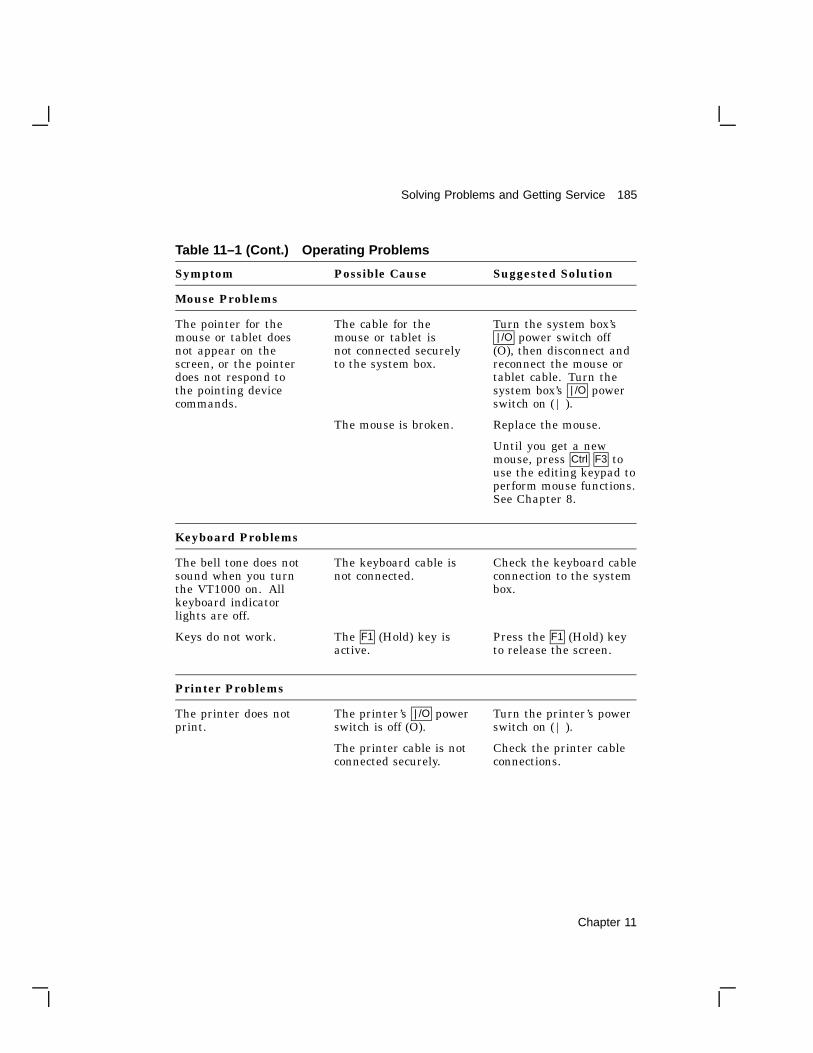
Solving Problems and Getting Service 185
Table 11–1 (Cont.) Operating Problems
Symptom Possible Cause Suggested Solution
Mouse Problems
The pointer for themouse or tablet doesnot appear on thescreen, or the pointerdoes not respond tothe pointing devicecommands.
The cable for themouse or tablet isnot connected securelyto the system box.
Turn the system box’s| /O power switch off
(O), then disconnect andreconnect the mouse ortablet cable. Turn thesystem box’s | /O powerswitch on ( | ).
The mouse is broken. Replace the mouse.
Until you get a newmouse, press Ctrl F3 touse the editing keypad toperform mouse functions.See Chapter 8.
Keyboard Problems
The bell tone does notsound when you turnthe VT1000 on. Allkeyboard indicatorlights are off.
The keyboard cable isnot connected.
Check the keyboard cableconnection to the systembox.
Keys do not work. The F1 (Hold) key isactive.
Press the F1 (Hold) keyto release the screen.
Printer Problems
The printer does notprint.
The printer’s | /O powerswitch is off (O).
Turn the printer’s powerswitch on ( | ).
The printer cable is notconnected securely.
Check the printer cableconnections.
Chapter 11

186 Solving Problems and Getting Service
Table 11–1 (Cont.) Operating Problems
Printer Problems
The communicationsettings on the terminaland printer do notmatch.
Make sure thecommunication settings(baud rate and parity)on the terminal andprinter match. Choosethe Printer Port... menuitem from the VT1000Terminal Manager’sCustomize Menu(Chapter 7.)
Network Problems
The host systemand terminal do notcommunicate.
The ThinWire Ethernetcable is not connectedsecurely to the systembox.
Check the Ethernetcable and T-connectorconnections.
There is no T-connectorbetween the connectoron the ThinWire cableand the system box.
Check that there is aT-connector betweenthe connector on theThinWire cable and thesystem box.
There is a ThinWiresegment between thesystem box and theT-connector.
Check that there isno ThinWire segmentbetween the system boxand the T-connector.(The T-connector mustattach directly to thesystem box).
A T-connector with aterminator has beendisconnected from anoperating ThinWireEthernet segment.
Check if a terminatorhas been removed ordisconnected from anactive ThinWire segment.
The system box port isinactive.
Make sure the port thatyour system cable isconnected to is active.
Chapter 11

Solving Problems and Getting Service 187
Power-Up Self-TestEvery time your turn the terminal on, the VT1000 automatically runs apower-up self-test. This test checks the operating status of many internalparts in the terminal. During the test, the keyboard lights turn on andoff. The power-up self-test should not take more than 45 seconds tocomplete.
If the test is successful, the bell tone sounds and the terminal displaysthe VT1000 Terminal Manager window.
If there were any test errors:
• A diagnostic message appears.
• The keyboard lights flash.
• The keyboard bell does not sound.
Screen Error Messages
If the VT1000 fails the power-up self-test, the terminal may display one ofthe error messages shown. Only qualified service personnel should try tocorrect these problems. You should note any error message that appearsand call Digital Customer Services.
Internal error or CPU error - 11External ROM error - 12External RAM error - 13NVR error - 14Host port error - 15Printer port error - 16DUART1 timer error - 17Keyboard port error - 18Mouse port error - 19DUART2 timer error - 21Video RAM error - 22Ethernet ROM error - 23Ethernet port error - 24Video error - 25Mouse error - 26Keyboard error - 27Trap interrupt error - 28Video control register error - 29I/O data path error - 31Illegal monitor error - 32LANCE not reset on power up - 33Image board error - 34
Chapter 11

188 Solving Problems and Getting Service
Digital ServiceDigital provides a wide range of maintenance programs that cover smallsystems and terminals. These include on-site, carry-in, and mail-inmaintenance services. You can use these programs to select the planthat suits your service needs.
Digital provides on-site repair and off-site repair services.
On-Site Hardware Services
Digital offers fast, low-cost, quality maintenance performed at your siteby Digital-trained Service Specialists. There are several on-site servicesavailable.
DECservice
DECservice provides preferred on-site service, with a guaranteed responsetime when equipment is located within a specified distance of the servicefacility. DECservice guarantees a continuous repair effort until service isrestored. You can choose the hours of coverage, up to 24 hours a day, 7days a week.
Basic
Basic offers priority response during regular business hours, Mondaythrough Friday.
Site SERVIcenter
If you have a least 50 terminals and can provide workspace at yoursite, Digital will provide an on-site technician for a predetermined,periodic time interval. The terminals may include a variety of models(for example, VT200s and VT300s.)
Per Call
This noncontractual offering provides on-site repair based on time andmaterials. Per call service is available during regular business hours,Monday through Friday.
DECall
DECall is similar to per call service, but has an annual retainer fee.DECall gives you on-site service at a fixed fee per repair call.
Chapter 11

Solving Problems and Getting Service 189
Off-Site Hardware Services
Digital also provides several options for off-site service.
Carry-in SERVIcenter
Digital SERVIcenters are located in major cities around the world. Theyoffer convenient, cost-effective repair service with a 48 hour turnaroundtime. Both contract and per call coverage is offered.
DECmailer
This is a mail-in service for module and subassembly repairs. DECmailerprovides five day turnaround.
Software Services
DECsupport
This program provides telephone and on-site remedial support (ifrequired), with personalized account focus and scheduled preventivemaintenance. Software updates, new releases, and access to Digital’sSoftware Information Network (DSIN) are included where available.
Basic
Basic service includes telephone support, software updates, new releases,and access to DSIN where available.
Self-Maintenance Service
This service provides software updates and new releases.
How To Get ServiceDigital has a central service center in your area to help you keep yoursystem running at peak efficiency. To find out more about Digital’shardware and software service offerings
In the United StatesCall 1-800-554-3333 during regular business hours.
Outside the United StatesContact your local Digital Customer Services Office.
Chapter 11

ASpecifications
A
This appendix lists the specifications for the VT1000 video terminal.
Site PlanningWeight Height Width Depth
System box 5.4 kg 60mm 394 mm 368 mm
(12 lb) (2.38 in.) (15.5 in.) (14.5 in.)
VR150 monitor 16.34 kg 394 mm 403 mm 368 mm
(36 lb) (15.5 in.) (15.9 in.) (14.5 in.)
VR262 monitor 18 kg 394 mm 455 mm 391 mm
(40 lb) (15.5 in.) (17.9 in.) (15.4 in.)
VR315 monitor 13 kg 400 mm 400 mm 395 mm
(29 lb) (15.7 in.) (15.7 in.) (15.4 in.)
VR319 monitor 27.2 kg 457 mm 495 mm 452 mm
(60 lb) (18 in.) (19.5 in.) (17.8 in.)
VRE01 monitor 7.7 kg 390 mm 427 mm 70 mm
(15 lb) (15.3 in.) (16.8 in.) (2.75 in.)
LK401 keyboard 1.4 kg 45 mm 478 mm 191 mm
(3.1 lb) (1.75 in.) (18.8 in.) (7.5 in.)
Mouse Weight Height Diameter
0.17 kg 41 mm 89 mm
(0.4 lb) (1.6 in.) (3.5 in.)
190 Appendix A

Specifications 191
EnvironmentOperating Storage
Temperature 10° to 40° C –40° to 66° C
(50° to 104° F) (–40° to 151° F)
Relative humidity 10% to 90% 0% to 95%
Maximum wet bulb 28° C (82° F)
Minimum dew point 2° C (36° F)
Maximum altitude 2.4 km (8000 ft) 9.1 km (30,000 ft)
ElectricalLine voltage (U.S.) 100 to 120 Vac nominal
88 to 132 Vrms operating range
single-phase, 3-wire
Line voltage (Europe) 220 to 240 Vac nominal
176 to 264 Vrms operating range
single phase, 3-wire
Line frequency 50 to 60 Hz
Input power 60 W maximum
Power cord Detachable, 3-conductor, grounded
Power cord receptacle EIA specified CEE22-6A
Appendix A

192 Specifications
Display (Monochrome Monitors)VR150 CRT 381 mm (15 in.)
Resolution 100 dots/in.
VR262 CRT 482 mm (19 in.)
Resolution 75 dots/in.
VR315 CRT 380 mm (15 in.)
Resolution 108 dots/in.
VR319 CRT 485 mm (19 in.)
Resolution 95 dots/in.
VRE01 flat panel 482 mm (19 in.) electroluminescent screen
LK401 KeyboardGeneral
General 108 sculptured keys with matte finish
Available in 16 language dialects and 15 wordprocessing versions, including English. ThreeFrench language keyboards.
Cord 1.8 m (6 ft) coiled cord with a 4-pin telephone-typemodular connector
Indicator lights 2 keyboard indicators:
Hold
Lock
Keys (Approximate Size)
Home row 30 mm (1.18 in.) above desktop
Key size 13 mm (0.50 in.) square
Key spacing 19 mm (0.75 in.) center to center (for single-widthkeys)
Appendix A
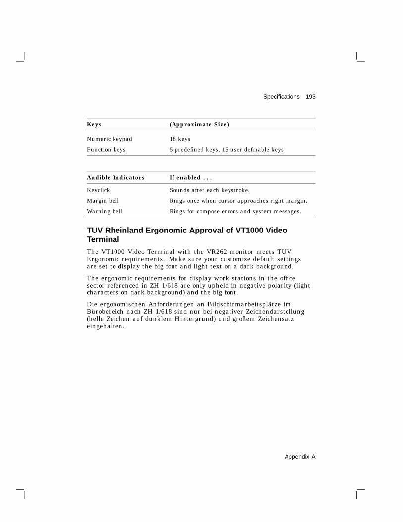
Specifications 193
Keys (Approximate Size)
Numeric keypad 18 keys
Function keys 5 predefined keys, 15 user-definable keys
Audible Indicators If enabled . . .
Keyclick Sounds after each keystroke.
Margin bell Rings once when cursor approaches right margin.
Warning bell Rings for compose errors and system messages.
TUV Rheinland Ergonomic Approval of VT1000 VideoTerminal
The VT1000 Video Terminal with the VR262 monitor meets TUVErgonomic requirements. Make sure your customize default settingsare set to display the big font and light text on a dark background.
The ergonomic requirements for display work stations in the officesector referenced in ZH 1/618 are only upheld in negative polarity (lightcharacters on dark background) and the big font.
Die ergonomischen Anforderungen an Bildschirmarbeitsplätze imBürobereich nach ZH 1/618 sind nur bei negativer Zeichendarstellung(helle Zeichen auf dunklem Hintergrund) und großem Zeichensatzeingehalten.
Appendix A

BOptions and Documentation
B
You can order the following options, modems, cables, and manuals forthe VT1000 video terminal from Digital. See the end of this appendix forordering information.
Optional Memory Boards
Option Part Number Description
Memorycontroller board
VX10X-MA Controller board for optional RAMmemory (comes with a 1 megabyteSIMM card preinstalled)
SIMM card VX10X-MD 1 megabyte SIMM card
ModemsPart Number Description
DF224 ScholarPlus
300, 1200, and 2400 baud, full-duplex asynchronous
DF224 300, 1200, and 2400 baud, full-duplex asynchronous
DF124 300, 600, and 1200 baud, full-duplex asynchronous
194 Appendix B

Options and Documentation 195
CablesPart Number Length Connector
Communication Cables
BC16E-10 10 ft (3 m) 6-pin M DEC-423
BC16E-25 25 ft (7.6 m) 6-pin M DEC-423
AC Power Cables Country
BN20V-2E Australia, New Zealand
BN20S-2E Austria, Belgium, Finland, France, Germany,Netherlands, Norway, Portugal, Spain, Sweden
BN20P-2E Canada
BN20U-2E Denmark
BN20R-2E Ireland, United Kingdom
BN19U-2E Israel
BN20W-2E Italy
BN20T-2E Switzerland
Related DocumentationYou can order the following related documents from Digital:
Document Order Number
VMS DECwindows User’s Guide AA-MG18A-TE
ULTRIX Workstation (UWS) User’s Guide
VT1000 Service Guide EK-V1000-PS
VT320 Programmer Reference Manual EK-VT320-RM
VR150 Pocket Service Guide EK-VR150-PS
VR262 Service Guide EK-VR262-PS
VR315 Monitor Service Guide EK-VR315-SG
VR319 Monitor Service Guide EK-VR319-SG
VRE01 Service Guide EK-VRE01-SG
Appendix B

196 Options and Documentation
Ordering InformationYou can order modems, supplies, and documentation by phone or by mail.
Continental USA and Puerto Rico
Call 800-258-1710 or mail to:
Digital Equipment CorporationP.O. Box CS2008Nashua, NH 03061
New Hampshire, Alaska, and Hawaii
Call 1-603-884-6660.
Outside the USA and Puerto Rico
Mail to:
Digital Equipment CorporationAttn: Accessories and Supplies Business Managerc/o Local Subsidiary or Digital-Approved Distributor
Appendix B

CCommunication
C
This appendix provides information on how the VT1000 communicateswith a host computer, printer, or modem. The appendix describes
• Network communication protocols for LAT and TCP/IP connections
• Serial communication for text terminal windows, printers, and modems
• Signals carried by the serial communication and pointing deviceconnectors on the back of the terminal.
The serial communication section shows the cables you can use fordifferent system configurations.
Network ProtocolsThe VT1000 can use two network communication protocols, local areatransport (LAT) and transmission control program/Internet protocol(TCP/IP). Each protocol connects the VT1000 to a host system throughan Ethernet network.
LAT Functions
The LAT protocol connects the VT1000 terminal to VMS or ULTRIX hostsin a local area network. The LAT protocol is Digital’s own local areanetwork protocol. The VT1000 complies with the architecture for LATVersion 5.1 with extensions to define the characteristics of service classes3 and 4.
The VT1000 supports LAT service classes 1, 3, and 4.
• Service class 1 lets the VT1000 run video terminal window (VTE)applications through the LAT on VMS and ULTRIX systems.
• Service class 3 lets the VT1000 run X window and DECwindowsapplications through the LAT on VMS systems.
Appendix C 197

198 Communication
• Service class 4 lets the VT1000 access font files through the LAT onVMS systems.
TCP/IP Functions
The TCP/IP protocol connects the VT1000 terminal to ULTRIX or UNIXhosts in a wide-area network. TCP/IP is an Internet wide-area protocol.
The VT1000 provides the following TCP/IP functions:
• Internet protocol (IP)
• Transmission control program (TCP)
• User datagram protocol (UDP)
• Boot protocol (BOOTP)
• Internet control message protocol (ICMP)
• Trivial file transfer protocol (TFTP)
• Virtual terminal connection service (TELNET)
• An Internet demon to accept in-bound X connection requests.
Serial CommunicationYou can connect the VT1000 to a host or terminal server with a DEC-4236-pin cable. The terminal has two serial communication ports, DEC-4236-pin host port and a DEC-423 6-pin printer port. You can also use theprinter port as a second host port, by changing settings in the CustomizePrinter Port dialog box (Chapter 7).
The terminal operates on full-duplex asynchronous lines only, with 10possible transmit and receive speeds. You can use split transmit andreceive speeds, but you must use the same speeds as your host systemand printer. To match the speed of your host system or local printer, usethe Customize Host Port or Customize Printer Port dialog box (Chapter 7).
Appendix C

Communication 199
Serial Communication Cables
You can connect the VT1000 directly to a local host system with a cable.You can also connect the terminal indirectly to a remote host system,using (1) a terminal server, or (2) a modem or acoustic coupler connectedto public-switched or dedicated telephone lines.
You can connect the VT1000 to an asynchronous serial printer by using anull modem cable.
To order cables for connecting the VT1000 to a host system or printer, seeAppendix B.
Serial XON/XOFF Flow Control
The VT1000 stores incoming characters in a character input buffer. Thebuffer can hold 254 characters. The terminal processes characters fromthe buffer on a first-in/first-out basis.
When the input buffer fills to 64 or 128 characters, the terminal sends anXOFF character to stop the host system from sending more characters.The default setting is 64. You can select from three settings—64, 128,or no XOFF—using the Customize Host Port or Customize Printer Portdialog box (Chapter 7).
NOTEIf you select No XOFF, the terminal does not send an XOFFcharacter to the host system when the input buffer fills. SelectingNo XOFF also disables the F1 (Hold) key. With XOFF disabled,there is no way to ensure that data will not be lost.
If the host system fails to respond to the XOFF character, the terminalsends a second XOFF character when the input buffer fills to 220characters. The terminal sends a third XOFF character when the bufferis full.
When the input buffer falls below 32 characters, the terminal sends anXON character to tell the host system to start sending characters again.
If you enable XON/XOFF, the terminal recognizes received XON andXOFF characters. When the terminal receives XOFF, it stops sendingdata (except XON/XOFF characters). If the keyboard data bufferoverflows, the keyboard locks. The terminal resumes transmission whenit receives an XON.
Appendix C

200 Communication
ModemsA modem lets the VT1000 communicate over a telephone line with aremote computer system. The modem converts the serial characterssent between the terminal and computer into signals that can travelover telephone lines. The modem you use with your terminal must becompatible with the modem used by the host system.
You can use a variety of modems with your VT1000, such as Digital’sDF224 modem. You can also use compatible modems, such as the AT&T103, 113, and 212 types. See Appendix B for information on orderingmodems.
The VT1000 must be certified for connection to non-AT&T type modemsused outside of continental North America. Your local Digital CustomerServices office has information on terminal certification and use of non-AT&T type modems.
To connect an approved modem to the VT1000:
1. Connect the modem cable to the 6-pin, DEC-423 host port on the rearof the terminal.
2. Display the Customize Host Port dialog box (Chapter 7).
3. Set the transmit and receive speeds to match your modem’s speeds.
Modem Connections and Disconnections
When the VT1000 makes a connection to a host system through a modem,the terminal performs the following operations to ensure it is ready tosend and receive:
• Unlocks the keyboard (if it was locked).
• Clears any transmisson in progress.
• Clears the keyboard buffer and all message buffers.
• Clears the input buffer.
• Clears XOFF sent and XOFF received.
Any of the following conditions will disconnect the connection to the hostsystem:
• You type Shift F5 (Break).
• You choose the Use Last Saved Settings or Use System Defaults menuitems from the Customize menu.
Appendix C

Communication 201
• The terminal loses the data set ready (DSR) signal.
• The terminal receives a self-test command from the host system.
The usual way to disconnect communications is to type Shift F5 (Break).The host system’s response to the disconnect signal depends on the systemand the software.
Break FunctionA break condition is the occurrence of a continuous space on acommunication line for greater than one character time. If you are usinga modem on a VMS operating system, this condition causes the modem todisconnect the terminal from the host system.
The F5 (Break) key has three functions.
• If enabled, pressing F5 (Break) sends a break signal to the host. Ifdisabled, you can still send a break signal to the host by typing Shift F5(Break).
• Pressing Shift F5 (Break) disconnects communications when you use amodem.
• Pressing Ctrl F5 (Break) sends the answerback message to the host.You enter the message by using the Customize VTE General dialog box(Chapter 5).
Communication Connector SignalsThe terminal has one DEC-423 host system (communication) connectorand one DEC-423 printer connector on the rear of the terminal. Table C–1describes the signals for both 6-pin connectors. The following figure showsthe pin numbers for the 6-pin connectors:
1 2 3 4 5 6
G S F _ 1 3 8 3 _ 8 9 . D G
Appendix C

202 Communication
Table C–1 6-Pin DEC-423 Communication and Printer Interface Signals
Pin Signal Mnemonic Description
1 Dataterminalready
DTR From VT1000When on, tells the modem or printer thatthe VT1000 is ready to send or receive.
2 Transmitdata
TXD+ From VT1000Sends serial characters. Held in the markstate (–) when characters are not beingsent.
In modem control modes, sends data onlywhen DSR and DTR signals are on.
3 Transmitsignalground
TXD– Provides the common ground referencepotential for transmitted signals TXD+and DTR.
4 Receivesignalground
RXD– Provides the common ground referencepotential for received signals RXD+ andDSR.
5 Receive data RXD+ To VT1000Receives serial characters.
6 Data setready
DSR To VT1000From the modem: When on, tells theVT1000 that it has a call connected.
From the printer: When on, tells theVT1000 that the printer is ready to print.If DSR is present at power-up, the printercontrols print operations. If DSR is notpresent at power-up, the terminal checksfor DSR before each print operation.
Appendix C

Communication 203
Pin Signals for the Pointing Device ConnectorThe terminal uses a 7-pin micro DIN connector for the pointing device.Table C–2 lists the connector pin assignments.
Table C–2 Pin Assignments for the Pointing Device Connector
Pin Signal Mnemonic
1 Protective ground GND
2 Transmit data TXD
3 Receive data RXD
4 — GND/–12
5 — +5
6 Not used —
7 Not used —
StandardsThe VT1000 operates in accordance with the following national andinternational communication standards:
EIA 232-DCCITT V.24CCITT V.28
CCITT V.10ISO 2110.2
Appendix C

DSystem Management Tasks
D
This appendix describes certain tasks a system manager must performin the LAT and TCP/IP environments to prepare the system to supportX applications on VT1000 terminals. The appendix also describes how torun a remote X window session on a VMS host that is not in your localarea (LAT) network.
The appendix is divided into three sections:
• LAT environment (VMS systems)
• TCP/IP environment (ULTRIX and UNIX systems)
• Running a remote X window session on a VMS system
Preparing the LAT Environment (VMS Systems)Perform the following steps to prepare your LAT environment to supportVT1000 terminals:
• Your system startup procedures will start the LAT driver, using theprocedure LTLOAD.COM.
• Do not call DECW$STARTUP from your SYSTARTUP_V5.COMcommand file. Under VMS Version 5.2 or higher, DECW$STARTUPis called from one of the system command files and not from yoursystem-specific SYSTARTUP_V5.COM.
• To start DECwindows terminal support, you must include the followinglogical in your system startup procedures before starting DECnet:
$ DEFINE/SYSTEM DECW$INSTALL_XTERMINAL TRUE
After the next reboot, your system will be ready to support the VT1000terminal.
204 Appendix D

System Management Tasks 205
If you do not want to start DECwindows terminal support on aparticular node, you may add the following to a root-specific startupfile:
$ DEFINE/SYSTEM DECW$INSTALL_XTERMINAL FALSE
LAT Font Path
By default, the VMS font daemon expands the nodename given in thefont path to <nodename>)::DECW$XTERMINAL_FONT. This logical isa searchlist that points to several subdirectories. To use another fontlibrary for custom applications instead of the DECWindows fonts, use thefull directory specification in the font path field of the terminal.
Preparing the TCP/IP Environment (ULTRIX andUNIX Systems)Perform the following steps to prepare your TCP/IP environment tosupport VT1000 terminals. These steps require Superuser privilege.
For Telnet VTE:
1. Edit /etc/inetd.conf to enable telnet .
2. Assign a network-wide IP address to the terminal.
3. Optional: Add the IP address to the network address table/usr/etc/bootptab and edit /etc/inetd.conf to enable bootp (ifavailable). (Allows terminal to automatically determine its IP addressat power-up.)
For X applications:
• Perform the steps above, plus:
4. Edit /etc/inetd.conf to enable tftp .
5. Create font file directory structures.
6. Create a font directory file pointing to the fonts for your terminal’sresolution (75 dots/inch or 100 dots/inch).
7. Enter the font path in the Customize Fonts window in the terminal.
Appendix D

206 System Management Tasks
1. Edit /etc/inetd.conf to enable telnet .
Edit the Internet daemon configuration file /etc/inetd.conf . Thefollowing example is taken from the sample file that ULTRIX provides,with most lines commented out. (This sample lists only the three linesthat are discussed in this chapter. Refer to it for bootp and tftp as well astelnet.)
The line starting with telnet should be uncommented (delete the leading# character) and completed, to enable VTE windows in the TCP/IPenvironment. Telnet is the network terminal protocol daemon (networklistener program).
# /etc/inetd.conf (Internet daemon configuration file):
## @(#)inetd.conf 4.1.1.4 (ULTRIX) 4/19/88# Internet server configuration database#telnet stream tcp nowait /etc/telnetd telnetdtftp dgram udp nowait /usr/etc/tftpd tftpd -r /tftpbootbootp dgram udp wait /usr/etc/bootpd bootpd -i
To make the /etc/inetd daemon read the edited file, use the followingcommand to get the processor status for inetd .
ps -lax | grep inetd
This command produces a display similar to this example:
F UID PID PPID CP PRI NI ADDR SZ RSS WCHAN STAT TT TIME COMMAND3000001 0 150 1 0 1 0 303c 62 40 c10e8 I ? 0:26 /etc/inetdb000001 268 3391 3383 0 1 0 4808 14 6 17518 S p2 0:00 grep inetd
The second line tells you the process ID number (PID) of the inetddaemon, which is 150 for this example.
The next command makes /etc/inetd restart and read the/etc/inetd.conf file to activate the edits made in the file.
kill -1 150
2. Assign an IP address.
Pick a unique number in your network address group. Enter the addressand a subnet mask value, using the terminal’s Customize TCP/IP dialogbox. Or, complete the next optional step and then click on the DetermineIP Address button in the Customize TCP/IP dialog box.
Appendix D
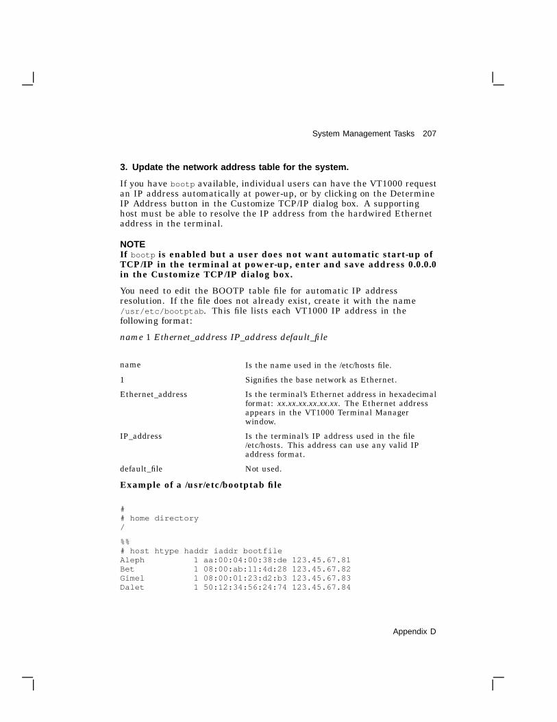
System Management Tasks 207
3. Update the network address table for the system.
If you have bootp available, individual users can have the VT1000 requestan IP address automatically at power-up, or by clicking on the DetermineIP Address button in the Customize TCP/IP dialog box. A supportinghost must be able to resolve the IP address from the hardwired Ethernetaddress in the terminal.
NOTEIf bootp is enabled but a user does not want automatic start-up ofTCP/IP in the terminal at power-up, enter and save address 0.0.0.0in the Customize TCP/IP dialog box.
You need to edit the BOOTP table file for automatic IP addressresolution. If the file does not already exist, create it with the name/usr/etc/bootptab . This file lists each VT1000 IP address in thefollowing format:
name 1 Ethernet_address IP_address default_file
name Is the name used in the /etc/hosts file.
1 Signifies the base network as Ethernet.
Ethernet_address Is the terminal’s Ethernet address in hexadecimalformat: xx.xx.xx.xx.xx.xx. The Ethernet addressappears in the VT1000 Terminal Managerwindow.
IP_address Is the terminal’s IP address used in the file/etc/hosts. This address can use any valid IPaddress format.
default_file Not used.
Example of a /usr/etc/bootptab file
## home directory/
%%# host htype haddr iaddr bootfileAleph 1 aa:00:04:00:38:de 123.45.67.81Bet 1 08:00:ab:11:4d:28 123.45.67.82Gimel 1 08:00:01:23:d2:b3 123.45.67.83Dalet 1 50:12:34:56:24:74 123.45.67.84
Appendix D
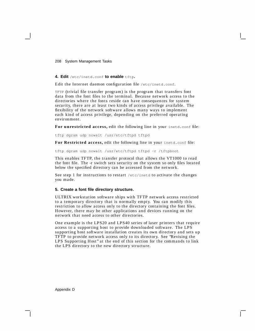
208 System Management Tasks
4. Edit /etc/inetd.conf to enable tftp .
Edit the Internet daemon configuration file /etc/inetd.conf .
TFTP (trivial file transfer program) is the program that transfers fontdata from the font files to the terminal. Because network access to thedirectories where the fonts reside can have consequences for systemsecurity, there are at least two kinds of access privilege available. Theflexibility of the network software allows many ways to implementeach kind of access privilege, depending on the preferred operatingenvironment.
For unrestricted access, edit the following line in your inetd.conf file:
tftp dgram udp nowait /usr/etc/tftpd tftpd
For Restricted access, edit the following line in your inetd.conf file:
tftp dgram udp nowait /usr/etc/tftpd tftpd -r /tftpboot
This enables TFTP, the transfer protocol that allows the VT1000 to readthe font file. The -r switch sets security on the system so only files locatedbelow the specified directory can be accessed from the network.
See step 1 for instructions to restart /etc/inetd to activate the changesyou made.
5. Create a font file directory structure.
ULTRIX workstation software ships with TFTP network access restrictedto a temporary directory that is normally empty. You can modify thisrestriction to allow access only to the directory containing the font files.However, there may be other applications and devices running on thenetwork that need access to other directories.
One example is the LPS20 and LPS40 series of laser printers that requireaccess to a supporting host to provide downloaded software. The LPSsupporting host software installation creates its own directory and sets upTFTP to provide network access only to its directory. See ‘‘Revising theLPS Supporting Host’’ at the end of this section for the commands to linkthe LPS directory to the new directory structure.
Appendix D

System Management Tasks 209
To allow access only to those files that are specifically intended for thenetwork but are in separate directories, Digital recommends that youcreate a generic network access directory (for example /tftpboot ) andthen add links to the authorized directories and files. This lets you avoidmoving files around, using extra disk space, or otherwise changing theexisting product installation procedures.
NOTEYou may have to re-edit the /etc/inetd.conf file after installingLPS supporting host software, because that installation procedurechanges the TFTP setup to be restricted to /usr/lib .
The following diagram shows the directory and link structure forUWS version 2.2 that allows network access to all needed files. Thisstructure may be expanded to accommodate other products. The link (...>)from /tftpboot to /usr/tftpboot is symbolic. The links between thetftpboot/*.pcf files and the lib/*.pcf files and between the similarsets of *.sys files are hard.
UWS Version 2.2 Directory Structure
/|
---------------------------------| |tftpboot/ usr/. |. ---------------------------------. | |...............>tftpboot/ lib/
| |----------------- -----------------| | | |vt1000/ iplps/ X11/ iplps/| | | || | | |75dpi/ sys/ fonts/ sys/| | | || | | |*.pcf *.sys decwin/ *.sys. . | ^. ................|................. 75dpi/. |..............................> *.pcf
Appendix D

210 System Management Tasks
Creating a Directory Structure
To create the directory, issue the following commands on the host. (Theinstructions are different for UWS Version 2.1 and Version 2.2, becausethe locations and file types of the font files changed between versions.)
For UWS Version 2.1
$ cd /$ mkdir /usr/tftpboot$ ln -s /usr/tftpboot /tftpboot$ cd /tftpboot$ mkdir vt1000$ cd /usr/lib/dwf$ find 75dpi 100dpi -print | cpio -pvdl /tftpboot/vt1000
For UWS Version 2.2
$ cd /$ mkdir /usr/tftpboot$ ln -s /usr/tftpboot /tftpboot$ cd /tftpboot$ mkdir vt1000$ cd /usr/lib/X11/fonts/decwin$ find 75dpi 100dpi -print | cpio -pvdl /tftpboot/vt1000
6. Create a font path definition file.
After the links to the font files have been created, font directory files needto be created.
To set an ULTRIX font path, the terminal looks for a font path file onthe font server host at the location specified in the Customize Font Pathdialog box. The terminal uses the contents of the font path file as a guideto the available fonts.
The terminal accesses fonts using TFTP. Users need to specify a font path.You need to create a file that specifies the location of each available font.This file must have world read access.
To create a font path file for VT1000 firmware Version 2.0 or higher, issuethe following commands on the host. (See the following instructions forFirmware Version 1.1 or higher.)
Appendix D

System Management Tasks 211
For UWS Version 2.1
Change directory to /tftpboot, and list the 75 dpi font file namesinto vt1000/75dpi/fonts.dir and the 100 dpi font file names intovt1000/100dpi/fonts.dir.
$ cd /tftpboot$ find vt1000/75dpi -name "*.dwf" -print > vt1000/75dpi/fonts.dir$ find vt1000/100dpi -name "*.dwf" -print > vt1000/100dpi/fonts.dir
For UWS Version 2.2
Change directory to /tftpboot/vt1000/75dpi, create a font directory file, andthen do the same for 100dpi.
$ cd /tftpboot/vt1000/75dpi$ dxmkfontdir$ cd /tftpboot/vt1000/100dpi$ dxmkfontdir
7. Enter a font path in the terminal.
Use one of the following font paths on your terminal:
For the VR262 or VRE01 monitors, use the 75 dots/inch fonts.
Unrestricted:
ROM,123.45.67.89:/tftpboot/vt1000/75dpi/fonts.dir
Restricted:
ROM,123.45.67.89:/vt1000/75dpi/fonts.dir
For the VR150, VR315, or VR319 monitors, use the 100 dot per inchfonts.
Unrestricted:
ROM,123.45.67.89:/tftpboot/vt1000/100dpi/fonts.dir
Restricted:
ROM,123.45.67.89:/vt1000/100dpi/fonts.dir
NOTESpecifying the TFTP font path in this way lets the terminal set thefont path in the least amount of time. If you only need to use onesize of fonts, Digital recommends this method.
Appendix D

212 System Management Tasks
For Firmware Version 1.1 or Higher,or When Using More Than One Font Directory at a Time
Use this procedure to provide support for:
• VT1000 Firmware Version 1.1 or higher.
• Simultaneous access to more than one font directory at a time.
You must create a font.paths file to direct the terminal to the multipledirectories.
For UWS Version 2.1
• Change the directory to /tftpboot/vt1000.
• Move all the lines in the two fonts.dir files into the font.paths file.
$ cd /tftpboot/vt1000$ cat 75dpi/fonts.dir 100dpi/fonts.dir > font.paths
For UWS Version 2.2
• Change the directory to /tftpboot/vt1000.
• Switch to the Bourne shell for the for command, if not already there.
• For both the 75dpi and 100dpi directories, copy only the lines thatcontain font file names from the font.dir files and insert the directorypath in front of the font file name.
• Put the names in the font.paths file.
$ cd /tftpboot/vt1000$ /bin/sh$ for i in 75dpi 100dpi> do> grep -v ’^[0-9]*$’ $i/fonts.dir | sed "s?^?$i/?"> done > font.paths
To access both the 75dpi and 100dpi fonts
Use the following font path on the terminal:
Unrestricted:
ROM,123.45.67.89:/tftpboot/vt1000/font.paths
Restricted:
ROM,123.45.67.89:/vt1000/font.paths
Appendix D

System Management Tasks 213
Revising the LPS Supporting Host
Use the following commands to set up the directory links to allow networkaccess to the supporting host software:
$ cd /tftpboot$ mkdir iplps$ cd /usr/lib/iplps$ find sys -print | cpio -pvdl /tftpboot/iplps
The path to the LPS supporting host code remains the same as before:
12.34.56.789:/iplps/sys/*.sys
Font Server Requirement for UWS Version 2.2 RISC
You cannot use a DECstation 2100 or DECstation 3100 (RISC) machinerunning software prior to UWS Version 2.2 as a font server. The fontsnative to the earlier UWS system will not work with the VT1000, and theattempt to set a font path will fail with no error message. An ULTRIX-32 system running UWS Version 2.1 or higher, or a VAX VMS systemrunning Version 5.3-1 or higher may be used as a font server for yourterminal if it is on the same Ethernet network.
Appendix D

214 System Management Tasks
Running a Remote X Window Session on a VMSSystemThis section describes how to use your VT1000 terminal to open an Xwindow session on one of the following:
• A host that is not in your local area (LAT) network
• A host running VMS Version 5.0–5.3
You must use DECnet to route the session through a host on yourlocal area network that supports the VT1000 (called LOCAL in thisexample). Using a few VMS DCL commands, you can run an X windowapplication or DECwindows session on a remote host (called REMOTE inthis example).
The XTerminal driver allows connections to a DECwindows terminalover DECnet by assigning a DECnet server number for the DECwindowsterminal on the supporting host. Without this, access to the DECwindowsterminal is limited to hosts running the DECwindows terminal supportpackage on the same Ethernet.
To use the DECnet Access Option, you must run DECW$DWT_DECNET with DECW$DISPLAY defined as the DECwindowsterminal. DECW$DISPLAY is defined for you if you are alreadyrunning a DECwindows session, or you can define it with the SETDISPLAY/CREATE command. Use the 12 characters of the LAT hostname in your VT1000 terminal for the node value in the examplecommand:
$ SET DISPLAY/CREATE/NODE=LAT_xxxxxxxxxxxx/TRANSPORT=LAT
Normally, DECW$DWT_DECNET chooses a server number for you.However, in this release, you must define a server number. The numberis arbitrary but cannot conflict with server numbers of other users ofDECW$DWT_DECNET on your system. Each user should use a differentnumber. Ask your system manager to assign a number to you. Then putthe following line, with the assigned server number (100 in this example),in your LOGIN.COM file on node LOCAL.
$ DEFINE DECW$DWT_DECNET_SERVER 100
To use the remote connection, you must provide a list on node LOCALof authorized remote accounts that can use the DECnet Access Option toaccess your terminal. Without this list, the terminal refuses all remoteconnections. Creating the list is a one-time activity, but you can update itat any time to allow additional connections.
Appendix D

System Management Tasks 215
The list is in a file in DECW$USER_DEFAULTS: (normally SYS$LOGIN:)called DECW$DWT_DECNET_AUTHORIZE.DAT. In this text file, eachline has three entries:
<transport> <remote node> <user>
For example: DECNET REMOTE USER1
Each line authorizes a single user to access the DECwindows terminalthrough the DECnet Access Option. There is no limit to the number oflines in the file.
The transport should be only DECnet.
$ CREATE DECW$USER_DEFAULTS:DECW$DWT_DECNET_AUTHORIZE.DATDECNET REMOTE USER1^Z
You can execute the command interactively to start the DECnetAccess Option, or you can put the following command in yourDECW$LOGIN.COM (executed when the DECwindows Session Manageris started). The server number is announced on SYS$OUTPUT whenDECW$DWT_DECNET is started.
$ SPAWN/NOWAIT/INPUT=NL: RUN SYS$SYSTEM:DECW$DWT_DECNET
The system replies with a message:
[Assigned DECnet server number 100 on node LOCAL][Remote display is server number 0 on
node LAT_xxxxxxxxxxxx using LAT transport]
You may press Return to get a system prompt, then you can log into theremote host. Execute the following command to establish a connectionbetween the DECnet servers on the supporting host and the remote host.The server number should be the predefined value from the earlier stepon the supporting host.
$ SET DISPLAY/CREATE/NODE=REMOTE/SERVER=100/TRANSPORT=DECNET
You can now start an X application on the remote host, and theapplikcation will be displayed on your VT1000.
Appendix D

Glossary
ANSIAmerican National Standards Institute
ASCIIAmerican Standard Code for Information Interchange. A set of 7- or 8-bitbinary numbers representing the alphabet, punctuation, numerals, andother special symbols used in text representation and communicationsprotocol.
ApplicationA program that performs a specific task.
CCITTComite Consultatif International de Telegraphique et Telephonique(International Telegraph and Telephone Consultative Committee). Astandards committee for the communication industry in Europe.
Character setA group of graphic characters and control characters stored as a unit inthe terminal. Graphic characters are characters you can display on thescreen. Control characters perform special functions.
Compose characterA character produced by pressing two or three keys in sequence, startingwith the Compose Character key or a diacritical mark key. You can usecompose sequences to produce characters that do not appear as standardkeys on your keyboard.
Computer systemA combination of system hardware, software, and external devices thatperforms operations and tasks.
216 Glossary

Glossary 217
CursorA blinking line or block on the screen that indicates the active position.
DEC Multinational character setThe default character set for the VT1000 terminal. The DECMultinational set is one of two 8-bit sets built into the VT1000. Theother set is ISO Latin-1. Both 8-bit sets include the standard ASCIIcharacter set and a supplemental set. For 7-bit environments, seeNational replacement character sets.
Data processing keysKeys that have three or four characters on the top of their keycap. Thecharacters on the right half of the keycap are data processing characters.To use data processing characters, you must choose the data processingversion of your keyboard in the Customize Keyboard dialog box.
DECconnectDigital’s cabling system for extending Ethernet and terminalinterconnections into offices and work areas.
DECnetDigital’s networking software that runs on nodes in both local and widearea networks.
Default optionA push button with a double outline, indicating the most frequently usedsetting for a window. You can choose a default option by pressing Returnor clicking on the push button.
Default settingA standard setting for one of the terminal’s operating features, set at thefactory. The VT1000 uses factory-default settings, unless you choose anew setting.
Device iconAn icon on the back of the system box that identifies the device that canbe plugged into the connector.
Diacritical marksMarks or symbols that indicate a change in the standard pronunciation ofa letter. Examples of diacritics are acute accent (’), grave accent (‘), andtilde (~). On the VT1000, you can use diacritical marks (if available onyour keyboard) to start two-stroke compose sequences.
Glossary

218 Glossary
EthernetA type of local area network, based on Carrier Sense Multiple Accesswith Collision Detection (CSMA/CD). A communication concept for localcommunication networks that use coaxial cable.
Filter rectangleA bounded area used defined on the screen. To activate the filter, youdefine its coordinates with a control function. If the terminal detects thatthe locator is outside the filter rectangle, the terminal sends an outsiderectangle event and disables the rectangle.
Font pathA logical file that lets a device access alternate character fonts for certainX window applications.
Full-duplex modemA modem that can handle simultaneous, two-way communications.
GraphicsThe use of lines, figures, shapes, and shaded areas to display information.
Graphics tabletAn optional device used to move the graphics input cursor on the screenand to enter data to an application program. Most tablets have threeparts: a tablet, stylus, and puck. To move the cursor you move the puckor stylus across the tablet. Also known as a locator device.
Group codeA number that represents a host or group of hosts on a LAT network.
HardwareThe physical equipment—mechanical and electrical—that make up asystem. Compare to Software.
Hardware Ethernet addressThe unique Ethernet physical address associated with a particularEthernet communications controller.
Host systemA computer system that has an active connection to your terminal. Theprimary or controlling computer in a multiple-computer network.
IconA graphic representation of an object, application, process, or window.
Glossary
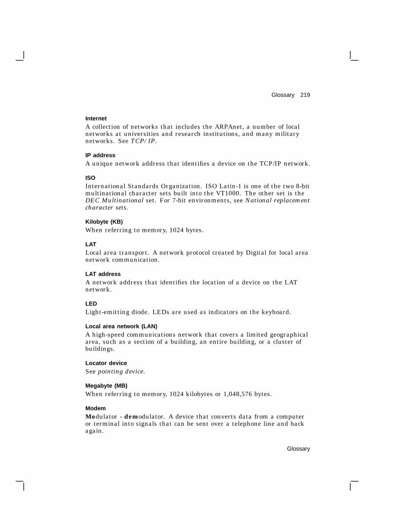
Glossary 219
InternetA collection of networks that includes the ARPAnet, a number of localnetworks at universities and research institutions, and many militarynetworks. See TCP/IP.
IP addressA unique network address that identifies a device on the TCP/IP network.
ISOInternational Standards Organization. ISO Latin-1 is one of the two 8-bitmultinational character sets built into the VT1000. The other set is theDEC Multinational set. For 7-bit environments, see National replacementcharacter sets.
Kilobyte (KB)When referring to memory, 1024 bytes.
LATLocal area transport. A network protocol created by Digital for local areanetwork communication.
LAT addressA network address that identifies the location of a device on the LATnetwork.
LEDLight-emitting diode. LEDs are used as indicators on the keyboard.
Local area network (LAN)A high-speed communications network that covers a limited geographicalarea, such as a section of a building, an entire building, or a cluster ofbuildings.
Locator deviceSee pointing device.
Megabyte (MB)When referring to memory, 1024 kilobytes or 1,048,576 bytes.
ModemModulator - demodulator. A device that converts data from a computeror terminal into signals that can be sent over a telephone line and backagain.
Glossary

220 Glossary
Modifier keyA key pressed in combination with another key, to modify the code sent bythat key. Ctrl is a modifier key.
Monochrome monitorA video screen that displays images in shades of one color.
MouseA handheld pointing device used to select menu options and drawgraphics. Moving the mouse across the desktop moves the pointer ormouse cursor on the screen. The mouse has three buttons that serve asfunction keys.
National replacement character sets (NRCs)Seven-bit character sets for many Western European languages. Each sethas 94 characters. NRC sets are similar to the ASCII set, except for a fewcharacters.
NetworkTwo or more computers linked by communication lines to shareinformation or resources.
Network coordinatorThe person who manages the network, assigns unique node names andaddresses for each VT1000 on the network, and provides administrativeassistance to network users.
NodeA computer, workstation, or peripheral device that is connected to anetwork and can communicate with other members of the network.
Nonvolatile memoryRandom access memory (RAM) that does not lose its contents when youturn the terminal off. The VT1000 uses this memory to store your savedcustomize settings.
PixelPicture elements. The smallest displayable unit on a video screen. Todisplay a character, the terminal turns on a series of pixels.
Pointing deviceA mouse or a graphics tablet, used with X window applications and menusto move the cursor on the screen. Also called a locator device.
Glossary

Glossary 221
PortA means for connecting one device to another. Usually, each port has anassociated connector.
Prefix keyA key that you press and release before pressing another key, to changethe function of one or more keystrokes. Compose Character is a prefix key.
Random access memory (RAM)Memory that can be read from and written to. The VT1000 uses thismemory to store instructions of programs currently being run.
Read-only memory (ROM)Memory that can be read from, but not modified. The VT1000 uses ROMmemory to store its operating code.
ReGISA serial geometric graphics display protocol created by Digital.
Scroll barA vertical or horizontal bar that lets you scroll information in theassociated window. The scroll bar includes stepping arrows and a sliderthat let you move at various rates.
ScrollingMoving information on the screen upward or downward to display moredata.
ServerHardware or software that provides a specific set of services to a client.
ServiceA name that represents a host or cluster of hosts that provides access tothat host or cluster.
SessionAn active connection between the terminal and the host system.
SixelA vertical column of six pixels. Screen displays can be printed in the formof sixel graphics.
Glossary

222 Glossary
SliderPart of a scroll bar that lets you scroll through information in a window.The size of the slider indicates how much of a file is currently displayed.The smaller the slider, the larger the file. The location of the slider in thescroll region indicates your relative position in the file.
SoftwarePrograms that perform a chosen or required function. Compare toHardware.
Stepping arrowPart of a scroll bar that lets you move incrementally through informationin a window.
SystemA combination of hardware, software, and peripheral devices that performspecific processing operations.
System managerA person who performs tasks necessary to operate and maintain thesystem. See Network coordinator.
TCP/IPTransmission control protocol/Internet protocol. The standard wide areanetworking software for the ULTRIX and UNIX operating systems.TCP/IP is a set of protocols developed by researchers centered aroundthe Advanced Research Projects Administration Network (ARPAnet).
Terminal serverAn intelligent unit that can connect a number of asynchronous devices(terminals and printers) to a host system. For example, Digital’sDECserver 200 can link eight VT1000 terminals to a system in a localarea network (LAN), using a high-speed Ethernet cable.
TerminatorA connector used on one or both ends of an Ethernet segment thatprovides the 50-ohm termination resistance needed for the cable.
ThinWire Ethernet networkA term to describe Digital’s 10base2 (IEEE standard 802.3 compliant)Ethernet products used for local distribution of data.
Glossary

Glossary 223
TransitionThe pressing or releasing of a locator button. The terminal can reporttransitions to the host system, using locator reports.
ULTRIXA UNIX based operating system created by Digital.
UNIXAn operating system created by AT&T.
User-defined keys (UDKs)Any of the 15 keys (F6 through F20) on the top row of the keyboard auser can define to perform specific functions.
Visual character attributeA quality of a display character that highlights the character, such asbolding and underlining.
VMSDigital’s proprietary operating system.
WindowAn area on your monitor screen that represents all or part of anapplication.
Window systemA windowing architecture that allows the execution and display ofapplications to be independent. Specific components of the architecturecontrol the display of applications and determine how applications run.Since its introduction by MIT, the X Window System has become anindustry standard.
Glossary

Index
<x
function, 85
AAccept Connections When Idle
button, 125Additional characters, 160 to 169
canceling a sequence, 163hexadecimal sequences, 164invalid sequences, 163table, 166
Alternate Shift key (German), 154,< and .> keys, 85Answerback message, 83
sending, 157Appl Cursor Keys button, 81Application Keypad button, 82Applications
moving between, 55running as icons, 57
Apply push button, 74, 113Arrow keys, 155
function, 81Audible indicators, 159Authorizing hosts
LAT or TCP/IP connections, 123Authorizing users, 122, 128Auto print mode, 88
selecting, 156Auto Repeat button, 85, 116Auto Resize Terminal button, 76Auto Wrap button, 78
B<x Backspace button, 85Baud rate
serial communication, 136Bell, 159Bell volume, 115Big font setting, 77BIND name servers, 1447-bit character sets, 1768-Bit Multinational Characters
button, 817-Bit NRC Characters button, 81Break function, 201Break key
See F5 key# £ key, 158
CCables
connections, 17ordering, 195
Cancel push button, 74, 113Character format
serial communication, 137Character sets, 7, 177
7-bit, 176DEC Technical, 176for printers, 89typing additional characters, 161VTE window
7-bit NRC sets, 86choosing a multinational set,
82
Index 1

2 Index
Character setsVTE window (Cont.)
selecting 8-bit or 7-bit, 81Clear Communications menu item,
68Clear Display menu item, 68Clicking
defined, 53Communication, 197 to 203
See also Serial communicationbreaking, 201breaking serial, 156modems, 200network problems, 186network protocols, 197pointing device
signals, 203serial, 198
cables, 199connector signals, 201XON/XOFF flow control, 199
standards, 203Components, 1
Compose Character key, 154, 162Compose sequences, 162Composing characters
See Additional charactersComputer sessions
See SessionsConceal Answerback Message
button, 83Condensed font setting, 77Confirm Quit Session button, 133Connectors, 17
system, 12Copying text, 69
disabled by some applications, 72host synchronization, 70selecting text, 71
Copy menu item, 70Create menu, 39, 45, 93Ctrl key, 153Cursor
blinking or steady, 79
Cursor (Cont.)style, 79text, 79
Customer serviceSee Service
Customize menu, 113Terminal Manager window, 32,
34, 112 to 150Customize Font Path dialog
box, 38, 44, 147Customize Host Port dialog
box, 135, 136Customize Keyboard dialog
box, 34, 115Customize Language dialog
box, 33, 118Customize LAT dialog box,
36, 138Customize Pointer dialog box,
119Customize Print Screen
dialog box, 120Customize Security dialog
box, 122Customize TCP/IP dialog box,
42, 142Customize TCP/IP Name
Server dialog box, 144Customize TCP/IP Routing
Tables dialog box, 145Customize Terminal Manager
dialog box, 132Customize Window dialog
box, 129display language, 118font path, 147host or printer port settings,
134keyboard settings, 115LAT settings, 138message displays, 132pointer and mouse settings,
119recalling settings, 114saving settings, 114security password, 128

Index 3
Customize menuTerminal Manager window (Cont.)
security settings, 122TCP/IP Name Server
settings, 144TCP/IP routing table settings,
145TCP/IP settings, 142window settings, 129
VTE window, 72VTE windows
Customize 7-BIT NRCSSelection dialog box, 87
Customize Keyboard dialogbox, 84
Customize Printer dialog box,88
Customize VTE Displaydialog box, 78
Customize VTE Generaldialog box, 80
Customize VTE Windowdialog box, 75
general settings, 80 to 83keyboard settings, 84 to 86saving and recalling settings,
74Customize Security Password dialog
box, 128Customize Security Password
problems, 184Customizing the VT1000
DECwindows Customize utility,112
from the host, 112Customizing the VT1000 Terminal
Manager window, 112
DData processing keys, 117, 157DEC-423 connectors, 201DEC Technical character set, 176 to
177DECwindows
DECwindows (Cont.)overview, 3
DECwindows sessionsSee X window sessions
Default optionschoosing, 62
<x Delete button, 85Diacritical keys, 161Diagnostic messages, 92Dialog boxes
description, 60Digital manuals
See Related documentation, 195Display Connection Requests button,
133Display Cursor button, 79Display Diagnostics Messages
button, 134Display language
choosing, 32 to 33Display Rejected Connection
Requests button, 134Double clicking
defined, 53Dragging
defined, 53
EEchoing data to the screen, 81Editing keypad, 155Edit menu, 69
Select All, 71Ending a session, 108Enter key, 155Error messages, 187
See Diagnostic messagesESC character, 86Ethernet problems, 186

4 Index
FF1 (Hold) key, 156, 199F2 (Print) key, 88, 156F5 (Break) key, 83, 156, 201Factory-default settings, recalling,
75, 114Font path
effect of double-size characters,180
Fontsfont path settings, 147 to 150font size and window size, 76for VTE windows, 77LAT font paths, 38TFTP font paths, 44
Function keys, 153, 156
GGroup codes
adding, 140enabling, 140removing, 140
Group Codes scroll box, 139Group Shift key (German), 154, 162
HHexadecimal key sequences, 164Hold key
See F1 keyHost-based window manager, 131Host port
connections, 104Host system connections
VT1000 Terminal Managersettings, 93 to 103
Host systemsaccessing LAT hosts, 96accessing TCP/IP hosts, 102group codes, 139
Host systems (Cont.)software support, 12
IIcon
expanding to a window, 58Icon Box, 131
rearranging icons in, 58storing a window in, 57
Iconsselecting icon names, 78
Indicator lights, 158Input buffer, 199Input focus
giving a window, 55Installation, 11 to 30IP addresses, 102, 142
BOOTP address resolution, 42domain name, 145entering, 42entering manually, 143primary name server, 145secondary name server, 145
IP address formats, 103IP subnet mask
entering, 42IP Subnet Mask, 143
K<> key, 86, 154Keyboard, 3, 151 to 159
auto repeat feature, 85connection, 18editing keypad, 155figure, 152indicator lights, 158local echo, 81main keypad, 152
function keys, 153model number location, 34numeric keypad, 155

Index 5
Keyboard (Cont.)problems, 185top-row function keys, 156warning bell, 84
Keyboard dialect, 151Keyboard language, choosing, 33 to
35Keyboard model
setting, 116Keyboard settings
Terminal Manager window, 115to 117
Keyboard type, 151Keyclick, 159Keyclick volume, 116
LLanguage
display, 118keyboard, 116
LA printersprint settings for, 90, 120
LAT communication protocol, 4address, 92creating a video terminal window,
95font paths, 38, 148functions, 197LAT group codes
entering, 36LAT Terminal Window Service
Select dialog box, 95password security, 128remote X window sessions, 214security, 122settings, 138tuning performance, 140X window and DECwindows
sessions, 100LAT Font Path button, 148Lights
See Indicator lightsLittle font setting, 77
Local Echo button, 81Locator device
enabling reports, 171locator report, 172locking and unlocking, 170request locator position, 174select locator events, 175
Lock Customize Security button, 126Locked Screens Visible button, 126Locking customize dialog boxes, 125Lock key, 153
setting, 116Lock Terminal Manager Customize
button, 126Lock UDKs button, 81Lock User Features button, 81Lock VTE Customize button, 126Logging out, 69
MMargin bell, 159Margin Bell button, 84Memory
checking available memory, 93Memory Remaining scale, 30
Memory controller boardinstallation, 21 to 30ordering, 194
Menuspull-down menu, 59
Messages
controlling displays, 132displaying, 133
Messages regionheader text, 134scroll lines saved, 134
Modems, 200breaking communication, 157connecting, 200ordering, 194
Monitorselection switch, 17

6 Index
Monitor (Cont.)specifications, 14
Monitors, 2problems, 184
Mouse, 3button layout, 119buttons defined, 52connection, 18figure, 52problems, 185settings, 119using, 52using the editing keypad as a
mouse, 155, 156
NNetwork
hardware support, 12Network addresses, 92Network problems, 186Network protocols
See also LAT and TCP/IPNewline button, 80Nodes
connecting to, 98viewing the list of, 98
No Form Feed button, 89, 122Normal Cursor Keys button, 81Normal font setting, 77Numeric keypad, 155Numeric Keypad button, 82
OOK push button, 74, 113Operating systems, 4Option button
defined, 61Options
ordering, 194
PParity, 137Part numbers
options, 194Password security settings, 128Paste menu item, 70Pasting text, 69, 71
host synchronization, 70QuickCopy, 72
Pausing a session, 106resuming the session, 108
PF1 to PF4 keys, 155Pointer settings, 119Pointing
defined, 53Ports
connecting to, 98Power supply, 23Power switch, 19Power-up self-test, 187Preferred Routes scroll box, 146Preferred Services scroll box, 98Pressing
defined, 53Printer controller mode, 89Printer port
choosing the function of, 137connections, 104
Printers, 110baud rate, 136problems, 185
Printingcanceling, 111from a video terminal window, 90from the host system, 88from VTE windows, 87
printed data type, 89print extent mode, 89print FF mode, 89Scroll Area button, 89
pixel aspect ratio, 121printer status, 111

Index 7
Printing (Cont.)print FF mode, 88, 122Print Screen menu, 110ribbon or toner saver, 122rotated image, 121the screen, 88under host control, 89
Print keySee F2 key
Print screen settings, 120Problems
See Solving problemsProgramming
character sets, 178enable filter rectangle (DECEFR),
170enable locator reports (DECELR),
171locator device commands, 169 to
176locator report (DECLRP), 172reports, 180 to 182request locator position
(DECRQLP), 174Select locator events (DECSLE),
175Pull-down menu
displaying, 59Push button
defined, 62Push-to-back button, 59
QQuickCopy, 72Quitting
a remote session manager, 109LAT X session, 101VTE window, 69
RRecalling feature settings
Terminal Manager window, 114VTE windows, 74
ReGIS graphics, 73Related documentation, 195Remote session managers, 100Remote window manager, 131Reset Terminal menu item, 68Resetting the terminal
secure reset, 93Resize button
using, 56Resize cursor, 56Resizing the display font, 76Return key, 153
selecting the function of, 80ROM board
installation, 21 to 30Rotate/Scale Picture button, 121
SSaving feature settings
Terminal Manager window, 114VTE windows, 74
Scaledefined, 61
Screen background pattern, 131color, 132
Screen saver feature, 130Scroll Area button, 89Scroll bar
using, 63Scrolling, 63
preventing, 85Scroll region, 63Secure reset count, 93Security settings, 122
accepting connections when idle,125

8 Index
Security settings (Cont.)adding authorized users, 124authorizing LAT or TCP/IP
connections, 123displaying a locked dialog box,
127locking customize dialog boxes,
125removing authorized users, 125security password, 128
Select All menu item, 70Serial communication, 198
baud rate, 136settings, 134
Serial connectionshost port, 104printer port, 104
Serial connector, 12Serial connectors, 18Service, 188 to 189Services
LAT, 97Preferred Services list, 98service list, 98X window, 100
Session manager, 47Session menu, 106, 108Sessions
ending, 47, 108LAT font paths
entering, 38LAT group codes
entering, 36opening
overview, 93pausing, 106quitting from a remote session
manager, 109starting, 35 to 47, 96
on an ULTRIX or UNIXsystem, 41 to 47
on a VMS system, 36 to 41on the serial host port, 47X window on a VMS system,
36 to 41
Sessions (Cont.)video terminal, 35X window, 35
Set-upSee Customize menu
Shift clickingdefined, 53
Shift key, 153Shrink-to-icon button, 57SIMM card
installation, 21 to 30ordering, 194
Site preparation, 11 to 13Sixel graphics, 73Sixel printing, 110Slider
using in scroll bar, 63Solving problems, 183Specifications, 190 to 193Start Session dialog box, 41Status display, 79Stepping arrow, 63System box, 2
connectors, 17problems, 183
System management tasks, 204System requirements, 4Systems
See Host systems
TTab key, 153TCP/IP
IP address, 92TCP/IP communication protocol, 4
creating a video terminal window,102
entering an IP address and hostname, 102
functions, 198name server, 143Name Server settings, 144password security, 128

Index 9
TCP/IP communication protocol(Cont.)
routing tables, 143routing tables settings, 145security, 122settings, 142
TELNET communication protocol, 4entering a port number, 103
TELNET Terminal Window HostSelect dialog box, 45, 102
Temporary Routes scroll box, 146Terminal ID button, 82Terminal Mode button, 83Terminal size setting, 77Text entry fields
typing in, 61TFTP font path, 149TFTP Font path button, 148TFTP font paths, 44ThinWire connector, 12, 18Tilde key, 86Title bar
moving a window with, 55Toggle button
defined, 61Typewriter keys, 117
UULTRIX operating system, 4
creating a video terminal window,102
font paths, 44IP addresses, 42running the DECwindows session
manager, 46sessions on the host or printer
port, 104starting a session, 35, 41 to 47
video terminal, 47TCP/IP Name Server settings,
144TCP/IP routing tables settings,
145TCP/IP settings, 142
ULTRIX operating system (Cont.)UWS version required, 12version required, 12X window or DECwindows
sessions, 102UNIX operating system, 4
creating a video terminal window,102
font paths, 44IP addresses, 42running the DECwindows session
manager, 46sessions on the host or printer
port, 104starting a session, 35, 41 to 47
video terminal, 47TCP/IP Name Server settings,
144TCP/IP routing tables settings,
145TCP/IP settings, 142version required, 12X window or DECwindows
sessions, 102Update Know Services button, 98UPSS DEC Supplemental button, 82UPSS ISO Latin 1 Supplemental
button, 82User-defined keys, 157
locking, 81User-preferred supplemental sets,
82Using the VT1000 Terminal
Manager window, 91
VVideo terminal sessions
description, 35on an ULTRIX or UNIX system,
41 to 47on a VMS system, 36 to 41
Video terminal window, 47See also VTE windowscustomizing, 112
10 Index
VMS operating system, 4creating a video terminal window,
95LAT group codes, 139LAT settings, 138sessions on the host or printer
port, 104starting a session, 35
video terminal, 36 to 41, 47X window, 36 to 41
version required, 12X window and DECwindows
sessions, 100X window sessions
remote, 214VT1000
network addresses, 92VT1000 terminal
components, 1overview, 1 to 7parts checklist, 16
VT1000 Terminal Manager window,32, 91 to 150
Create menu, 93Customize window, 112features, 91figure, 91Print Screen menu, 110Session menu, 106
VTE window, 7quitting, 69
VTE windows, 66 to 90,< and .> keys, 85angle bracket keys, 86answerback message, 83Auto Repeat button, 85auto wrap setting, 78blinking or steady cursor, 79block or underline cursor, 79character set selection, 81, 82choosing a 7-bit NRC character
set, 86clearing, resetting, or leaving, 68Commands menu, 68
VTE windows (Cont.)Conceal Answerback Message
button, 83creating
on an ULTRIX or UNIXsystem, 102
on a VMS system, 95on the host or printer port,
104cursor key functions, 81Customize 7-BIT NRCS Selection
dialog box, 87Customize Keyboard dialog box,
84Customize menu, 73Customize VTE General dialog
box, 80Customize VTE Printer dialog
box, 88Customize VTE Window dialog
box, 75customizing, 72 to 90display cursor, 79display settings, 78font size, 77format, 66<x function, 85general settings, 80 to 83icon name, 78keyboard settings, 84 to 86keypad function, 82Lock UDKs button, 81Lock User Features button, 81Margin Bell button, 84printer settings, 87 to 90rows and columns, 77saving and recalling settings, 74status display, 79Terminal ID button, 82Terminal Mode button, 83text and window background, 79tilde key as ESC key, 86VTE Customize menu, 80Warning Bell button, 84

Index 11
WWarning bell, 115, 159Warning Bell button, 842-Way Printer Port button, 89Windows, 51 to 65
changing the size of, 56changing the size of icons, 131defined, 53expanding from an icon, 58foreground color, 132moving, 55popping to the top of the stack,
59selecting, 55settings
Terminal Manager window,129
VTE windows, 75shrinking, 57stacking, 59
VT1000–DECwindowsdifferences, 51
Window title, selecting, 77
XXOFF signal, 137X window client, 46X window sessions
canceling a login box, 101creating
on an ULTRIX or UNIXsystem, 102
on a VMS system, 100description, 35on an ULTRIX or UNIX system,
41 to 47on a remote VMS system, 214on a VMS system, 36 to 41TCP/IP X window session, 105
X Window System, 3