this document is best - dtic
TRANSCRIPT


THIS DOCUMENT IS BEST
QUALITY AVAILABLE. THE
COPY FURNISHED TO DTIC
CONTAINED A SIGNIFICANT
NUMBER OF PAGES WHICH DO
NOT REPRODUCE LEGIBLY.
)tj I.. J 1 4. LJ^ "
■
('■
i
i
•c *
i
f i
c
*INACTIVE TERMINAL* > NO CARRIER
Session disconnected.
*MS6 DI4 0ROLS PROCESSING-LAST INPUT IGNORED
»MSG DI4 pfiOLS PROCESSING-LAST INPUT IGNORED
»HSG DI4 DROLS PROCESSING-LAST INPUT IGNORED
*MSG M4 DROLS PROCESSING - LAST INPUT IGNORED
- 1 OF 1 " «"OTIC DOES NOT HAVE THIS ITEM»« " 1 - AD NUMBER: D439308 -- 6 - UNCLASSIFIED TITLE: ELECTROSTATIC POWDER COATING, "10 - PERSONAL AUTHORS: HUGHES,J. F. ; "11 - REPORT DATE: , 1934 "12 - PAGINATION: 137P -20 - REPORT CLASSIFICATION: UNCLASSIFIED "22 - IMITATIONS (ALPHA): APPROVED FOR PUBLIC RELEASE; DISTRIBUTION
UNLIHITED. IVimii'iDILITYi ?0llll IllkP a COIIOi IIICii HDD Tllinp mi , nrii rtnr) ii v iniro /
•-33 - LIHITATION CODES: 1 J^ /
-- END Y FOR NEXT ACCESSION
'^:P-^^^i^:^m^-:-^
END
f:si-/;?^t^;w3^|^^-:^
'■•'^■<c^.:.W^.': ;;.,;.; '~:iiX. '■^'^'J'iS '. '.■'jflS
'^&;^^'^^i^^rj^0^':^i0^-A^^M^

19951214 003

Electrostatic Powder Coating

ELECTRONIC & ELECTRICAL ENGINEERING RESEARCH STUDIES
ELECTROSTATICS AND ELECTROSTATIC APPLICATIONS SERIES
Series Editor: Dr. J. F. Hughes, Department of Electrical Engineering, University of Southampton, England
1. Static Elimination T. Horvath and I. Berta
2. Electrostatic Hazards in the Petroleum Industry W. M. Bustin and\N. G. Dukek
3. Electrophotography Principles and Optimization Merlin Scharfe
4. Electrostatic Powder Coating J. F. Hughes
lessssi-oa IS'op
mi's, ®Mi n n

Electrostatic Powder Coating
J. F. Hughes, PhD, CEng, MIEE, FInstP University of Southampton, UK
fir I IK flffi %DEC1J5]1995]i mi
m SSfflS*'
tJ^^iC QMLITY ISisj^-
RESEARCH STUDIES PRESS LTD. Letchworth, Hertfordshire, England
_ JOHN WILEY & SONS INC. ^ New York ■ Brisbane ■ Chichester ■ Toronto • Singapore

RESEARCH STUDIES PRESS LTD. 58B Station Road, Letchworth, Herts. SG6 3BE, England
Copyright © 1984, by Research Studies Press Ltd.
All rights reserved.
No part of this book may be reproduced by any means, nor transmitted, nor translated into a machine language without the written permission of the publisher.
Marketing and Distribution:
Australia, New Zealand, South-east Asia: Jacaranda-Wiley Ltd., Jacaranda Press JOHN WILEY & SONS INC. GPO Box 859, Brisbane, Queensland 4001, Australia
Canada: JOHN WILEY & SONS CANADA LIMITED 22 Worcester Road, Rexdale, Ontario, Canada
Europe, Africa: JOHN WILEY & SONS LIMITED Baffins Lane, Chichester, West Sussex, England
North and South America and the rest of the world: JOHN WILEY &SONS INC. 605 Third Avenue, New York, NY 10158, USA
Library of Congress Cataloguing in Publication Data:
Hughes, J. F. (John Farrell), 1943- Electrostatic powder coating. (Electronic & electrical engineering research
studies. Electrostatics and electrostatic applications series; 4)
Bibliography: p. Includes index. 1. Plastic coating. 2. Spray painting. Electrostatic.
I. Title. 11. Series. TP1175.S6H84 1984 667.9 84-10673 ISBN 0 86380 018 1 ISBN 0 471 90569 0 (Wiley)
British Library Cataloguing in Publication Data:
Hughes, J. F. Electrostatic powder coating.—(Electronic & electrical engineering research studies. Electrostatics and electrostatic applications series; 4) 1. Spray painting. Electrostatic I. Title II. Series 667.9 TT315
ISBN 0 86380 018 1 ISBN 0 471 90569 0 (Wiley)
ISBN 0 86380 018 1 (Research Studies Press Ltd.) ISBN 0 471 90569 0 (John Wiley & Sons Inc.)
Printed in Great Britain

To ; Christine, Carys and David.

Acknowledgements
Fundamental research into electrostatic powder coating has been
acjtivelj carried out at Southampton University for a period of about
15 years. The author is indebted to the many colleagues who have
contributed to this activity. A major part of the funding for this
research was made available by the Science and Engineering Research
Council, with generous contributions from many powder and equipment
manufacturers. The advice and suggestions of Dr. J. R. G. Pude
on mathematical modelling techniques are gratefully acknowledged.

Preface
Fundgmental phenomena which govern the performance of powder
costing, equipment are often complicated and not always obvious in
terms of practical implications on plant performance. Many scienti-
fic papers have been published in International Journals and
conference proceedings, some of which will be referred to in the
list of references and bibliography.
J.v; This monograph attempts to combine, in one concise volume, some of
the most important practical implications drawn from in-depth
research investigations. Mathematical relationships have been
deliberately avoided whenever possible so as to introduce and
familiarise the uninitiated reader with powder coating terminology
and practical requirements. Nevertheless, the more experienced
reader should find useful hints and design guides especially in the
chapters on measurement techniques and system optimization.
The final chapter on future trends reviews some of the more recent
innovations, and attempts to identify techniques that may contribute
to future developments in powder coating technology.

Introduction
The"distribution of a liquid in an even, thin protective layer over
a surface has for many years been the method adopted for either
protecting the substrate and/or enhancing its appearance. Distribu-
tion of the coating, or paint, is usually effected by one of three
ways: brush, roller or spraying.
Ihe apparent simplicity of the basic requirement is, however,
misleading in many ways. Not only does the chemistry of the paint
require meticulous attention, but so does the condition of the
substrate onto which it is to be deposited. The interfacial condi-
tions between substrate and paint have to be such that good adhesion
is achieved when the solvents evaporate and the paint dries. This
is a complicated chemical problem in itself, and will not be dealt
with here. However, it is important to appreciate from the outset
that 'painting' is a much more complicated and scientifically-
exacting process than is generally presumed.
Liquid paint is widely used in manufacturing industries where
invariably some type of coating is deposited on the finished product.
Distribution of the paint by atomization into a fine aerosol lends
itself very well to substrate coating, and numerous commercial
coating systems are available. Some systems use air atomization
while others adopt centrifugal forces for disruption of the
continuous phase liquid into fine droplets. Numerous variations and

XI1
hybrids have been marketed, each with its own unique claim in terms
of performance suitability to special requirements. A relatively
recent innovation in coating has been the added sophistication of
imparting electrical charge to the atomized paint particles. Again,
this has been achieved in a number of ways including corona charging
and induction charging, the net result being an improvement both in
coating efficiency and evenness of coating thickness. Electrostatic
painting soon became an established method of coating especially in
the automobile and domestic appliances industries, with the now .■^
familiar 'wrap-around' characteristics contributing to an improvement..,
in plant efficiency. Crop spraying of insecticides and herbicides
has also benefited from electrostatic charging of liquid aerosol,
which have produced an increase in the efficiency of deposition on
vegetation and a decrease in the overall volume of chemical used ;
important environmentally as well as cost advantage.
Probably the greatest limitation associated with wet paint spraying
is that each particle or droplet has only one chance of achieving its,
objective - that of alighting on the workpiece. Particles that miss
the workpiece are irretrievably lost in the capture system used in ;
the coating booth. Sometimes the back walls of coating booths are
water washed and the overspray is captured and discarded. In order
to minimize overspray, and thus achieve maximum economic benefit,
precise setting-up procedures for a gun-booth system are of paramount
importance. These may be relatively straightforward, although tend
to rely more on operating experience than scientific technique when
a single type and size of workpiece is handled. In reality, of
course, a typical coating line will be loaded with a variety of work-
pieces, changing from day-to-day or even from hour-to-hour. Under
such conditions, it is difficult to see how gun systems can be
maintained finely tuned to yield maximum performance.
It is the inability to reclaim overspray, together with the now
high cost of petroleum-based solvents that has contributed more
than any other factor to the development of dry powder paint alterna-
tives. The elimination of a wet base, solvent or water,facilitates

Xlll
reclamation of oversprayed paint - an important economic advantage
which promises a potential 100% utilization of paint plus elimination
of expensive solvents that are flushed-off and inevitably wasted.
Thus electrostatic powder coating was conceived, and indeed has grown
largely on these potential benefits. A variety of dry powdered paints
were developed and these are now widely used in large quantities,
-. milking important inroads into areas where wet coating once dominated.
Th-6' transition has not been easy, however, and many unforeseen
difficulties were encountered - not least that of imparting unipolar
-erec-t'rical charge to solid isolated particles. Powdered products are
notorrously difficult to handle compared to liquids, especially in
terms of accurate metering and conveying through pipes. However,
despite these difficulties, the advantages of using dry paint have
outvjeighed the technical difficulties envisaged in the early stages
of development. Early pistol application equipment was little more
than a straight piece of pipe through which powder was blown, with
a high-voltage corona charging electrode situated at the exit nozzle.
■ This 'technique appeared to work reasonably well and became the model
for all subsequent pistol development, such that many currently-used
•powder guns differ little from their early predecessors, being little
more than corona points at the end of pipes. This approach may have
been acceptable initially, but modern coating lines dictate a degree
of sophistication which is difficult to find in most commercial
arrangements. The constant search for better quality coatings
coupled with higher deposition efficiency and faster line speeds
has pushed most equipment to the limits of its performance capa-
bility. In order to achieve superior performance, the entire powder
^ coating system has to be reappraised, and a more scientific approach
must be adopted in relation to system optimization. It is no longer
acceptable to point a pipe/corona point combination at a workpiece.
This monograph draws primarily from research work carried out at
Southampton University over a period of about 15 years. Both funda-
mental and practically-orientated research programmes have been
sponsored by the Science and Engineering Research Council, powder
manufacturers and coating equipment manufacturers. Many aspects of

xiv
the work have already been published in technical journals and
presented at International Conferences, and reference to these may
be found throughout the text. In this single volume, some of the
more important fundamental considerations are presented together with
an attempt at highlighting the practical implications of experimentally-
verified phenomena. A discussion of measurement techniques, followed
by a critical review of some of the new and novel coating systems ,
completes the text.

Table of Contents
' ■ '■' , Page
" '• - ;V -• No.
Acknowledgements vii
Preface ix
INTRODUCTION xi
CHAPTER 1 PARTICLE CHARGING 1
, Fundamental considerations 1
Corona charging of particles 1
Tribo or frictional charging 8
Induction charging 12
Ion wind 15
Back-ionization 20
Practical implications 27
CHAPTER 2 MEASUREMENT TECHNIQUES 29
Resistivity 29
Charge-to-mass ratio (q/m) 40
Gun potential and current 47
Electric field 54
CHAPTER 3 APPLICATION EQUIPMENT AND BOOTHS 61
Pistol applicators 61
Fluidised beds 64
Other systems 69
Coating booths 82
Page No.
CHAPTER 4 SYSTEM OPTIMIZATION 91 96 Booth and gun air gy
Gun voltage and current 99 Earthing
CHAPTER 5 FUTURE TRENDS ^^^-v
Equipment . „ , 109 ■; Powders : ":,
1-12' " Computer-aided modelling ,: , ,,^
SUMMARY ■ '■'"■'"^ 121
INDEX

List of Illustrations
.'■'?i.gV. ■'■ Page NO.. No.
1.1 Field intensification at a sharp point. 2
1.2 Simplified energy level model for electron injection. 3
1.3 Corona charging in pistol applicators. 4
1.4' Ionic charging of electrically insulating particles. 5
1.5 Maximum surface charging of isolated particle 6
1.6 The charge exchange mechanisms across two solid interfaces. 10 (a) Non-frictional, energy level model. (b) Frictional, material transfer model.
1.7 Tribo-charging of insulating particles. 13
1.8 Charging of conducting particles by induction. 14
1.9 Ionic-induced air movement.
1.10 Typical electric field line configuration. 17
1.11 The Faraday Cage effect. 19
1.12 Typical coating patterns for (a) corona charged gun; 20 (b) tribo-charged gun.
1.13 Simple model of layer thickness limiting. 21
1.14 Powder layer growth using corona-charged gun. 22
1.15 Back-ionization in powder layer. 22
1.16 Back-ionization on epoxy coated flat plate. 24

Fig. Page No. No.
1.17 Double image arrangement for back-ionization evaluation. 26
1.18 Energy measurements of back-ionization. 26
2.1 Schematic of powder resistivity test cell. 31
2.2 Powder resistivity test meter. ' 3'^ ■
2.3 Electric field measurement on charged powder layer. 35
2.4 A typical exponential decay plot of electric field
versus time.
2.15 Field intensification due to presence of field mill in charged cloud.
3.1 Schematic of simple fluidised bed coater.
3.2 Typical commercial fluidised bed system.
3.3 Inherently safe fluidised bed.
3.4 Simplified details of pistol applicators. (a) Conventional corona charging. (b) Low voltage corona charging.
36
2.5 Charge conduction paths in packed powder sample. 37 (a) Bulk conduction; (b) Surface conduction.
2.6 Method for measuring surface resistance.
2.7 Simple Faraday cup arrangement.
2.8 Schematic of ion-trap in powder stream.
2.9 Irrigated grid device for absolute measurement of q/m.
2.10 Powder coating test-set.
2.11 Schematic of resistor chain voltage probe.
2.12 Electrostatic voltmeter. 51
2.13 Rotating vane type field mill. 55
2.14 Modified field mill head with air purge facilities.
39
42
42
43
46
49
58
65
66
68
70

Fig. Page No. No.
3.5 Detail of low voltage gun. 73
3.6 Schematic of corona-assisted tribo gun. 75
3.7 Cyclo-Gun. (a) Complete system; 77 (b) Detail of gun nozzle.
3.8 , Typical air-less blade-coater. 79
,3^9 :, Typical powder disc system. 80
3.10 Conveyor loop with disc coater. 81
3.11 Electric field lines configuration between gun and 84 workpiece. (a) Earthed metal booth. (b) Electrically insulating booth.
3.12 Simplified schematic of Volstatic Super Coater system. 85
3.13 Schematic cross-sectional view of electric curtain tile 87
3.14 Schematic of electric curtain booth. 89
3.15 Schematic of bottle coater using electric curtain booth 90 panels.
5.1 Irrigated grid showing effects of back-ionization on 108 layer deposition. (a) Dry grid. Back-ionization. (b) Irrigated grid. No back-ionization.
5.2 Typical flow diagram for powder coating programme. 113

CHAPTER 1 Particle Charging
FUNDAMENTAL CONSIDERATIONS
The prime requirement of all powder coating systems is that of
imparting electrical charge, usually unipolar, to individual
particles. In order to complete the process, the charged particles
then have to be manipulated such that they alight and adhere on what
is usually a grounded metal subststrate. The movement of the
particles between the charging station and substrate is usually
governed by either electrical or mechanical forces, or a combination
of both. Electrical forces are created by the interaction between
the charged particles and the electric field between substrate and
gun, while mechanical forces are those resulting from air being
driven through the gun. As will become clear later, these two forces
are of paramount importance in terms of the overall behaviour and
performance characteristics of individual coating systems.
When considering the basic requirement of imparting charge to a
particle, it helps to simplify the situation by assuming the particles
are spherical and that most paints will be electrically insulating;
that is, assume a bulk resistivity in excess of 10^^ Qm. So how do
electrically isolated, highly insulating particles become charged?
CORONA CHARGING OF PARTICLES
This is perhaps the most widely used method of particle charging in
both pistol and fluidised bed coaters. In its simplest embodiment,
the charging electrode may be a sharp pointed needle-like electrode.
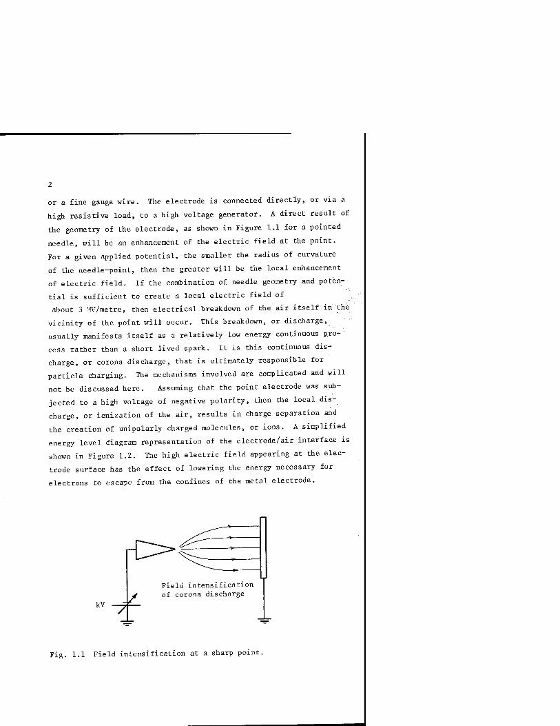
or a fine gauge wire. The electrode is connected directly, or via a
high resistive load, to a high voltage generator. A direct result of
the geometry of the electrode, as shown in Figure 1..1 for a pointed
needle, will be an enhancement of the electric field at the point.
For a given applied potential, the smaller the radius of curvature
of the needle-point, then the greater will be the local enhancement
of electric field. If the combination of needle geometry and poten^.
tial is sufficient to create a local electric field of
about 3 fW/metre, then electrical breakdown of the air itself in the
vicinity of the point will occur. This breakdown, or discharge,
usually manifests itself as a relatively low energy continuous pro^
cess rather than a short lived spark. It is this continuous dis-
charge, or corona discharge, that is ultimately responsible for
particle charging. The mechanisms involved are complicated and will
not be discussed here. Assuming that the point electrode was sub-
jected to a high voltage of negative polarity, then the local dis-
charge, or ionization of the air, results in charge separation and
the creation of unipolarly charged molecules, or ions. A simplified
energy level diagram representation of the electrode/air interface is
shown in Figure 1.2. The high electric field appearing at the elec-
trode surface has the effect of lowering the energy necessary for
electrons to escape from the confines of the metal electrode.
r^
kV "7 -/
Field intensification of corona discharge
Fig. 1.1 Field intensification at a sharp point.

Energy
Effective reduction in work function
metal electrode
Work function
electric field at electrode tip (v/m)
Fig. 1.2 Simplified energy level model for electron injection.
Almost instantly after transition from metal to air, the high
mobility electrons are rapidly trapped by air molecules creating a
low mobility negative ion.
It is these slower moving negative ions, which drift away from the
charging electrode under the action of the electric field, that are
ultimately responsible for particle charging. The ions are created
at the gun nozzle, and tend to accumulate near the electrode creating
a space charge before drifting towards the workpiece. This space
charge usually occurs when the rate of ion creation exceeds the rate
at which they drift away from the discharge region. Powder particles
emanating from the gun nozzle travel through this space charge,
picking up ions on their flight between gun and workpiece. Figure
1.3 illustrates schematically the situation that might exist in a
typical gun system.
The situation is already becoming much more complicated than ori-
ginally envisaged. In reality, the gun projects not one, but three
species of 'particles' at the workpiece. Not just charged paint
particles, but also uncharged paint particles and negative ions.
Later, we shall see how this complicates the fundamental understand-
ing of the powder coating process, and raises many difficulties both
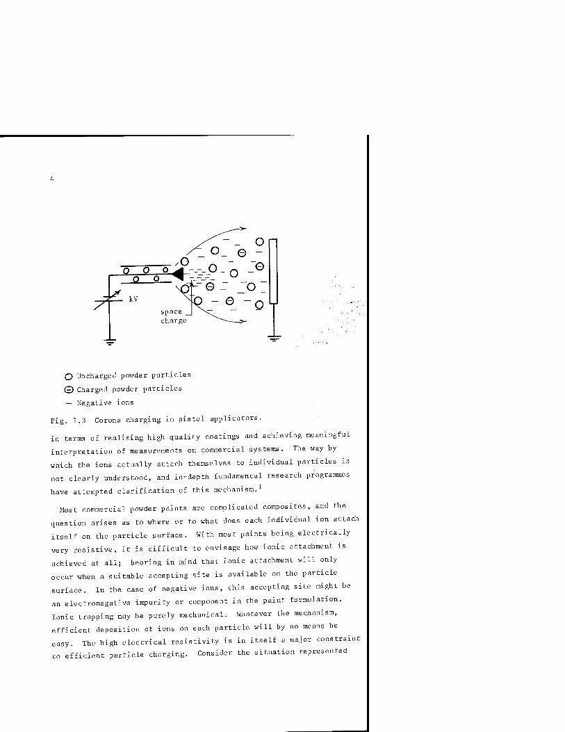
O Uncharged powder particles
© Charged powder particles
— Negative ions
Fig. 1.3 Corona charging in pistol applicators.
in terms of realising high quality coatings and achieving meaningful
interpretation of measurements on commercial systems. The way by
which the ions actually attach themselves to individual particles is
not clearly understood, and in-depth fundamental research programmes
have attempted clarification of this mechanism.^
Most commercial powder paints are complicated composites, and the
question arises as to where or to what does each individual ion attach
itself on the particle surface. With most paints being electrically
very resistive, it is difficult to envisage how ionic attachment is
achieved at all; bearing in mind that ionic attachment will only
occur when a suitable accepting site is available on the particle
surface. In the case of negative ions, this accepting site might be
an electronegative impurity or component in the paint formulation.
Ionic trapping may be purely mechanical. Whatever the mechanism,
efficient deposition of ions on each particle will by no means be
easy. The high electrical resistivity is in itself a major constraint
to efficient particle charging. Consider the situation represented

in Figure 1.4.
insulating particle
Fig. 1.4 Ionic charging of electrically insulating particles.
As the particles and ions drift towards the workpiece at different
velocities, it is feasible that some ionic collection will occur as a
result of direct impaction with the particle surface. Assuming that
the ions, on impaction, are retained on the surface, then each ion is
'locked' into position at the exact point of impaction. Since the
surface resistance of the average particle will be high, then no sur-
face conduction will occur over the surface as a result of particle
re-distribution - unlike conducting particles where the charge
density of the entire surface of a spherical particle will be con-
stant due to surface migration. For insulating particle^, therefore,
the situation depicted schematically in Figure 1.4 might well be the
norm. That is, particles arriving at the substrate with uneven sur-
face charge distribution in the form of immobile charge islands.
With this inability to redistribute over the particle surface, it is
not difficult to appreciate the fundamental difficulty associated
with efficient charging of insulating particles.
The model suggested here for ionic charging of isolated particles
is of course oversimplified, but nevertheless serves a useful purpose
in terms of understanding the fundamental difficulties associated
6
with efficient ionic capture.
For complete and accurate-modelling of such a situation, other
considerations need to be taken into account. For example, an
isolated particle in an ionic cloud will tend to accumulate ions
until its potential equals that of its surroundings. In an ideal
spherical model situation, it might be acceptable to assume that
ionic motion towards the particle will be uniform in all directions,
and therefore the surface charge distribution will be uniform. This
may be so in a situation where the particle may be perfectly motion-
less - a condition hardly likely to occur in reality in a gun system.
Another important consideration is the fact that, associated with all
isolated particles, there will be a maximum surface charge density
which cannot under any circumstances be exceeded. This is known as
the Pauthenier limit, and is of prime importance when modelling
particle charging situations and evaluating the charging efficiency
of various systems.^ This will not be described in detail, but a
superficial appreciation of the mechanism would be useful for future
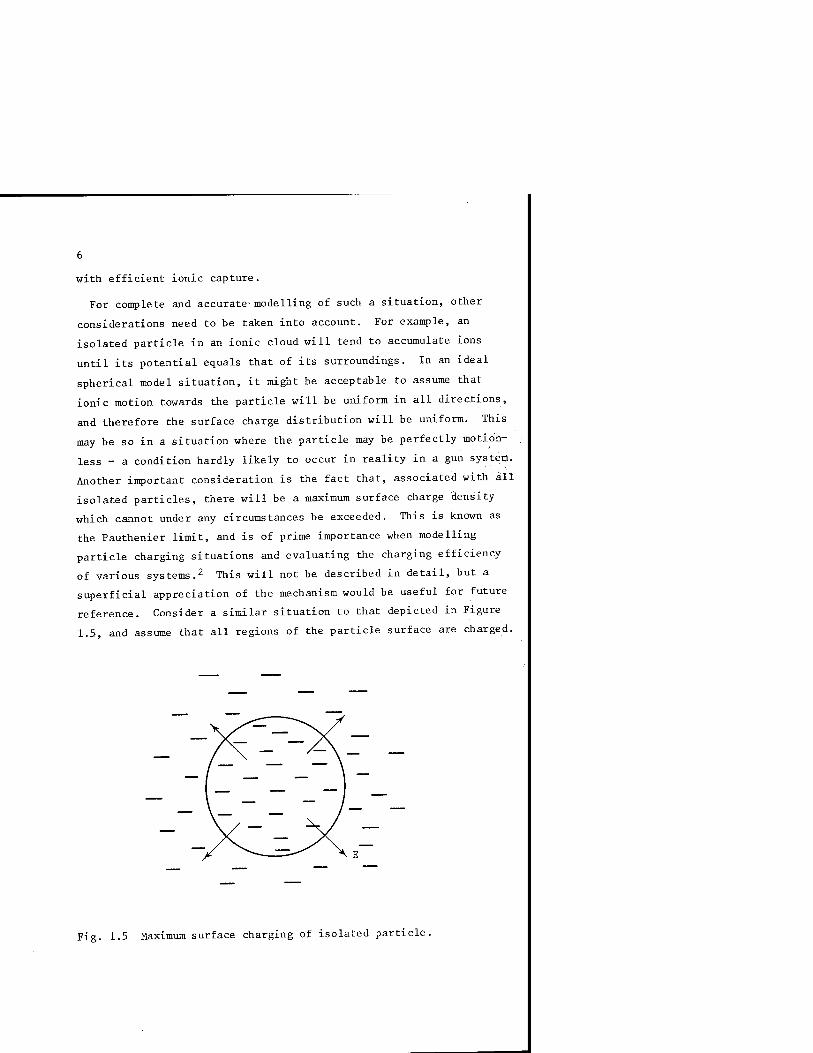
reference. Consider a similar situation to that depicted in Figure
1.5, and assume that all regions of the particle surface are charged.
Fig. 1.5 Maximum surface charging of isolated particle.

Under normal circumstances, the movement of ions onto the surface will
cease when the potential of the particle equals that of its surround-
ings. An electric field, E, will be created as a result of this
surface charge, and will be the field at the interface between the
particle and its surroundings, as shown in Figure 1.5. With con-
tinued increase in charge collection, E will increase until a value is
reached which corresponds to a situation where no further transport of
ions onto the particle will be possible. This limiting value of sur-
face charge, the Pauthenier limit, may be expressed mathematically by
the following relationship:-
(1) Q = 4lT e a2 0
B E
B = 1 + 2 ^S- -1)
(E^+1)
—12 — 1 and e = permittivity of free space = 8.854 x 10 F.m .
E = relative permittivity of powder particle.
a = radius of particle.
E = electric field which particle is subjected to.
For a spherical particle its mass 'm' will be:-
^ 3 m = ^ TT a^ p (2)
where p = density of particle.
So, the charge to mass ratio, q/m, will be:-
- - ^ - 3eBE q _ 0 0 m 4 = 3
(3) -IT TT a-^ p pa
Substituting the following typical values of:-
Ej. = 2, E = 10^ vm~^, a = 50 X 10~^ ra
e = 8.854 X lo"'^ F.m"' and p = 10"^ kg.m"'^
into equation (3) gives the maximum value of q/m at the specified
field as:-
( ^ ) = 8.8 x lO"^ C/kg . ™ max
So far, we have considered only negative charging of isolated
particles. If positive charging is used then previous statements
relating to charge behaviour and Pauthenier limit are still valid;
but the actual mechanism of the corona discharge at the electrode
point will be different. With positive high potential applied to the
electrode, electrons will now have to be stripped from neutral air
molecules thus creating positive ions, which in turn migrate towards
the earthed workpiece and interact with powder particles in a manner
identical to that of negative ions. The electrons are rapidly V_ '
collected by the charging electrode. As for negative ions,.both the
mechanism of capture on the surface of each particle, and the
mechanism of ionic attachment - electrical, mechanical or a combina-
tion of both - are unclear. After deposition of the particles on the
workpiece, the behaviour of the coating will differ according to
whether the particles are negatively or positively charged. This
important factor is discussed later in relation to back-ionization.
TRIBO OR FRICTIONAL CHARGING
One of the earliest electrical phenomena to be documented and
investigated was associated with the fact that when two different
materials were in contact and subsequently separated, they appeared
to display characteristics which implied that electrical charge had
been exchanged during their period of contact. This phenomenon is
now widely experienced in everyday life, especially with the advent
of electrically insulating man-made fibres. Electrical charging and
sparking associated with nylon shirts and carpets, for example, are
common occurrences. While fundamental mechanisms relating to this
charge exchange will not be discussed in detail, a superficial under-
standing of the mechanisms involved^'^ will be attempted.
In the case of two different solid materials brought into contact,
the usual result is an imbalance in charge between the two molecular
layers that are in intimate contact. Depending on the crystallogra-
phic and chemical structure of the two materials, re-organisation of
charge will occur across the interface in an attempt to restore
electrical balance. This migration of charge will usually be by

electronic conduction or transfer, and the degree and direction of
migration will be dictated primarily by what is known as the Tribo-
electric Series.^ This model uses the concept of the energy level
diagram similar to that shown in Figure 1.2. That is, the relative
positions of electronic energy levels in each material, when brought
into contact, determine the direction in which electronic transfer
will- take place. Many of the most common materials used in electri-
cal engineering have been evaluated in terms of their position in the
' fribo series, which facilitates a degree of predictability in terms
"of;,charge exchange behaviour. For materials which have not been
evaluated,.however, predicting the direction of electronic transfer
when in contact with a different material will require some conjec-
ture .
All materials, solids and liquids, display this charge exchange
phenomenon. Charge exchange will occur across all solid/solid,
solid/liquid and liquid/liquid interfaces. For many materials, the
occurrence of charge re-organisation at the interface will not be
obvious. This is primarily because most materials are electrically
conducting; thus charge transfer across the interface occurs simul-
taneously with relaxation and neutralization of the charge by virtue
of the conductivity of the material. Only when the materials are
electrically insulating does the charge exchange result in the long-
term creation of unipolar charge either on the surface of solids, or
within the bulk of liquids. In fuel handling systems, this can be
especially hazardous when electrically insulating and highly flam-
mable hydrocarbon fuels are pumped at high velocities, for example
in aircraft refuelling systems. Due to the charge exchange mechanism,
unipolarly charged fuel may accumulate in the fuel tanks, resulting
in high energy discharges leading possibly to fires and explosions.^
Since this is not relevant to the present discussion, the emphasis
will be on charging of solid surfaces.
Tribo-charging is a prime example of an electrical phenomenon
which is not completely understood. Much research has been devoted
in an attempt to produce a more precise model of the interface

10
phenomena. The complex models proposed are beyond the scope of the
present discussion, but it is relevant that at least two mechanisms
may be responsible for charge exchange across a solid interface.
This is the electronic transfer mechanism associated with the elec-
tronic energy levels, and this model is the one primarily used for
non-frictional contact. In the event of a sliding, or frictional
contact, however, an additional mechanism might be involved. During
frictional contact, it has been established that some degree of
material transfer may actually occur from material to material. A -
direct result of this will be a change in the net charge on each , -
surface, leading to an effective charge exchange across the interface.
Probably, in the case of particle charging in a coating system, a
combination of these two mechanisms will be responsible for some
degree of tribo-charging as the powder is delivered from the hopper,
through the feed pipes and into the gun itself. Figure 1.6 illus-
trates a much simplified model of the way in which the two main charge
exchange phenomena can result in particle charging.
In Figure 1.6(a), assuming the energy levels associated with trapped
electrons are higher in Material 2, than Material 1, then electronic
transfer will occur from 2 into 1 until an effective equalisation of
the upper energy levels is achieved.
Q Q QQQ
Material 1
eee o
(a)
Material 2
Material 1 >-
Material 2
(b)
Fig. 1.6 The charge exchange mechanisms across two solid interfaces. (a) Non-frictional, energy level model. (b) Frictional, material transfer model.

11
In this case, material 1 would retain a net negative charge while
material 2 would retain an equal and opposite net positive charge.
This energy level model must be used with caution, however, since it
is a model which has been developed specifically for semiconductor
materials, and relies on long-range crystallographic order for
meaningful interpretation. Most insulating materials display only
short-range crystallographic order, and therefore the energy level
model can only be truly representative of the material behaviour over
short distances within its bulk. Accepting this restriction, then it
"-is-nevertheless a useful model which facilitates an understanding of
fhe'basic mechanism of charge migration across an interface.
Figute 1.6(b) is a schematic representation on a molecular scale of
the interface between two materials. True contact is only achieved
between the high-spots, or peaks, on the actual surfaces. Assuming
relative movement between these two surfaces, it is not difficult to
envisage how the high spots may be sheared and some degree of
material interchange can occur between the two surfaces.
In powder coating, most of the powder paints used are highly
insulating; if tribo-charge exchange mechanisms exist, then it is
very likely that their effect will be noticeable. In other words,
the powder particles will retain their charge, and likewise, the
inside surfaces of the guns and feeding hoses will retain an equal
and opposite charge. Almost all commercial coating systems will
include a component of tribo-charging; it is very unusual to find
systems that do not tribo-charge to some extent. Some systems rely
entirely on tribo-charging, and these will be reviewed in detail
later.
By its very nature, tribo-charging is notoriously unpredictable and
its characteristics can vary according to the material and the
ambient conditions - especially relative humidity. Even in corona
charged guns, an appreciation of the tribo-charging component can be
important in terms of overall gun behaviour. When tribo-charging is
high, then the polarity of the corona charging should be chosen so
that the two mechanisms interact constructively. However, other
12
factors need to be considered when choosing polarity; these will be
discussed later together with the implications of back-ionization.
In summary, the result of blowing insulating powder particles
through a gun is retention by the particles of a net electrical
charge - either positive or negative. Some commercial guns utilise
this phenomenon, relying entirely on tribo-charging to effect parti-
cle charging. In relation to the coating process, there is a subtle
difference between corona charged and purely tribo-charged particles.
In Figure 1.3, three species of 'particles' are identified. In •
tribo-charged guns, no free ions are created, resulting in a system
producing only two species: charged particles and uncharged particles.
Generally, there will be no high potential at the end of the gUn, and
the subsequent particle migration mechanism and trajectories from gun
to workpiece will be quite different for corona and tribo-charged
guns .
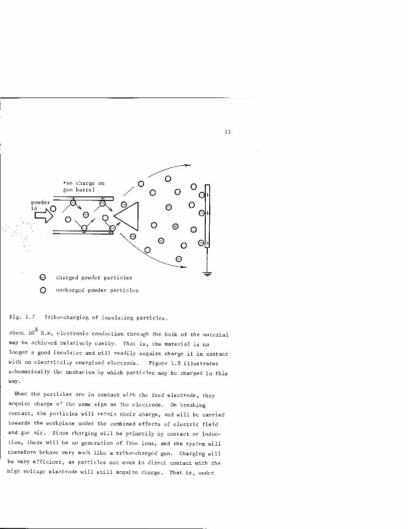
Figure 1.7 illustrates schematically the tribo counterpart of the
corona system illustrated in Figure 1.3.
An equal and opposite charge to that of the particles will be
deposited on the inside wall of the gun barrel. With continued use,
this will have detrimental effects on the long-term charging charac-
teristics of tribo-guns (see Chapter 3). The deposition field is
primarily that due to the charged powder cloud itself, and particle
trajectories will be dictated more by the air flow than by electrical
effects .
INDUCTION CHARGING
There is a third method of charging which is perhaps not as
familiar as corona and tribo-charging, although it is widely used in
liquid charging systems. This is known as the mechanism of charging
by induction, or influence. Generally, the technique requires the
particle to be charged, be it liquid or solid, to be relatively
conducting compared to the usual powder paint materials; and this is
probably why induction charging has not featured as an important
alternative in powder coating. For materials of resistivity below
13
+ve charge on gun barrel
'-v o e ^—^
Q charged powder particles
O uncharged powder particles
Fig. 1.7 Tribo-charging of insulating particles.
Q
about 10 fi.m, electronic conduction through the bulk of the material
may be achieved relatively easily. That is, the material is no
longer a good insulator and will readily acquire charge if in contact
with an electrically energised electrode. Figure 1.8 illustrates
schematically the mechanism by which particles may be charged in this
way.
When the particles are in contact with the feed electrode, they
acquire charge of the same sign as the electrode. On breaking
contact, the particles will retain their charge, and will be carried
towards the workpiece under the combined effects of electric field
and gun air. Since charging will be primarily by contact or induc-
tion, there will be no generation of free ions, and the system will
therefore behave very much like a tribo-charged gun. Charging will
be very efficient, as particles not even in direct contact with the
high voltage electrode will still acquire charge. That is, under
14
feed electrode
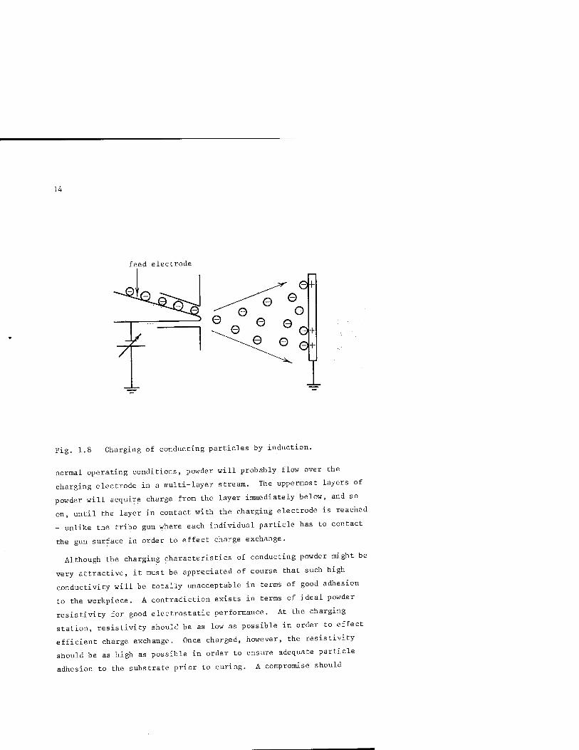
Fig. 1.8 Charging of conducting particles by induction.
normal operating conditions, powder will probably flow over the
charging electrode in a multi-layer stream. The uppermost layers of
powder will acquire charge from the layer immediately below, and so
on, until the layer in contact with the charging electrode is reached
- unlike the tribo gun where each individual particle has to contact
the gun surface in order to effect charge exchange.
Although the charging characteristics of conducting powder might be
very attractive, it must be appreciated of course that such high
conductivity will be totally unacceptable in terms of good adhesion
to the workpiece. A contradiction exists in terms of ideal powder
resistivity for good electrostatic performance. At the charging
station, resistivity should be as low as possible in order to effect
efficient charge exchange. Once charged, however, the resistivity
should be as high as possible in order to ensure adequate particle
adhesion to the substrate prior to curing. A compromise should

15
ideally be sought, where both requirements are fulfilled at least to
give acceptable overall performance. This Same constraint appears to
exist also in other applications requiring particle charging and
manipulation, notably electrostatic precipitation and electro-
photography .
In powder coating there would appear to be little evidence that
powder manufacturers are considering electrical resistivity as an
important parameter in the formulation Of their final product.
Powders destined for use in electrostatic equipment have not in
general been optimized in terms of their electrical characteristics
and their suitability for accommodating charge. Further improvement
in coating efficiency and behaviour is dependent on the availability
of more electrostatically-tailored powders.
ION-WIND
In understanding the behaviour of charged particles in a typical
coating system, the effects of free ions on system behaviour as well
as the practical implications on overall coating quality are
important. The effects of ion wind are generally confined to systems
with external corona charging, typical of that shown in Figure 1.3.
The trajectories of the uncharged particles will be dictated primari-
ly by the air flow pattern, while for the charged particles and ions
an additional force, that of the electric field between gun head and
workpiece,will also contribute to particle behaviour. It is the
interaction between the movement of charged particles and ions and
the electrically neutral air in which they are suspended which in
turn gives rise to an additional component of forward velocity.
Since the ions are much smaller and have a much higher mobility 2 — 1 — 1
(mobility = velocity per unit field, m .v .s ) than the paint
particles, then their motion between gun and workpiece is very rapid.
It is the collection of ions on the workpiece which accounts for the
main current path between gun and workpiece. During their free-
flight period, the ions will collide repeatedly with neutral air
molecules. Momentum exchange will take place, resulting in an
induced motion of the air itself in the same direction as the ions.
16
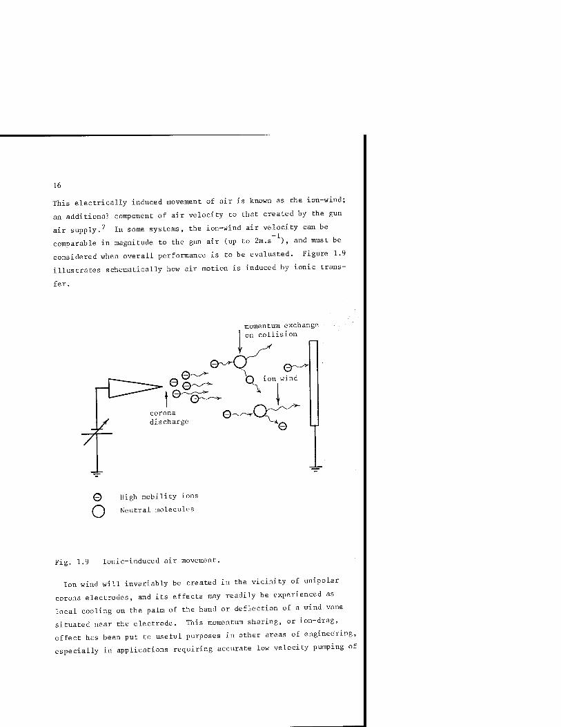
This electrically induced movement of air is known as the ion-wind;
an additional component of air velocity to that created by the gun
air supply.^ In some systems, the ion-wind air velocity can be
comparable in magnitude to the gun air (up to 2m.s ), and must be
considered when overall performance is to be evaluated. Figure 1.9
illustrates schematically how air motion is induced by ionic trans-
fer.
momentum exchange on collision
0 High mobility ions
(~^ Neutral molecules
Fig. 1.9 Ionic-induced air movement.
Ion wind will invariably be created in the vicinity of unipolar
corona electrodes, and its effects may readily be experienced as
local cooling on the palm of the hand or deflection of a wind vane
situated near the electrode. This momentum sharing, or ion-drag,
effect has been put to useful purposes in other areas of engineering,
especially in applications requiring accurate low velocity pumping of

17
liquids. Injection of charge into a liquid, together with the
application of high field, has resulted in the now familiar ion-
pumps" : a useful innovation if moving parts present in a conven-
tional pump could detrimentally affect the product being handled.
The implications of ion-wind are important, and should not be
underestimated. Even in so-called air-less guns, there will
normally be a substantial component of forward air velocity which
will dictate to a large extent just where each particle will alight
qn the workpiece. For example, the traditional schematic representa-
tion of the performance of an electrostatic gun system is similar to
that shown in Figure 1.10. The electric field lines shown are said
to describe both the trajectories of charged particles, and the way
in which coating of the rear, or shadow area, of the workpiece
becomes possible as a result of wrap-around.
~7r~
Fig. 1.10 Typical electric field line configuratic
Charged particles will tend to follow the lines of electric field
enabling complete coating with just one gun. This theoretical model
would accurately describe typical trajectories. However, in reality,
since the combined effects of gun air and ion-wind are substantial.
18
the actual particle trajectories will be very different to that shown
in Figure 1.10. It has been shown that pneumatic forces predominate
for most of the particle trajectory between gun and workpiece, and
only when the charged particle is within about 2 cm of the surface of
the workpiece do the attraction forces between it and its image charge
begin to take over.^ There is now strong evidence that for efficient
coating, and for effective wrap-around, then powder has to be
pneumatically projected onto the workpiece - or at least to within a
few centimetres of its surface. The implications of this are.
important, and alter drastically the simplified scheme in Figure 1.10.
Air flow patterns are as important, if not more important than the.
electric field configuration. Turbulence must be induced in order to
achieve good wrap-around, and air velocities near the workpiece sur-
face should not exceed the electrical image attraction force.
The original simple electrostatic model does not represent the
original situation. Air flow has complicated the system and has
probably contributed more than any other factor to the difficulties
associated with system optimization. At the present time there are
few guidelines to indicate optimum air flow in commercial systems,
and system behaviour is usually approached empirically.
The secondary importance of electric field lines configuration is
further demonstrated by the apparent effectiveness of tribo-guns for
coating irregularly shaped workpieces. Wrap-around generally appears
to occur just as effectively with tribo-charged guns where the
deposition field is essentially eliminated. In practice, there will
exist a small but finite electric field between the gun and work-
piece, and this will be due primarily to the charged powder cloud
itself. This is usually referred to as the space charge field.
Elimination of the deposition field has unforeseen advantages,
especially when the interior of cavities and corners are to be
coated. For a convex geometry as depicted in Figure 1.10, the field
lines may assist with particle movement and deposition on the sur-
face. For a geometry similar to that shown in Figure 1.11, however,
quite the opposite situation will occur. As a direct result of

19
Fig. 1.11 The Faraday Cage effect.
Gauss' Law^", no field lines can exist, nor penetrate, areas that
approximate to being surrounded by the earthed metal boundary of the
workpiece. This has become known as the Faraday Cage effect, and is
an illustration of one of the classical laws of electrostatics.
Most lines of electric field will terminate on the outside surface
of the workpiece section shown in Figure 1.11. With low gun air
velocity, particles will tend to follow more predictably the field
line pattern, resulting in minimal penetration of the inside surface
of the workpiece. This contrasts with a typical tribo-gun arrange-
ment, where the electric field will be either zero or negligible, and
particle trajectories will be dictated primarily by air flow.
Pneumatic conveyance of the particles into the workpiece cavity will
ensure internal coating and image charge attraction will complete the
objective of depositing particles on the surface. Although the
superiority of tribo-charged guns over corona-charged guns for
internal coating is generally accepted, the explanation is relatively
recent. Figure 1.12 illustrates typical coating behaviour expected
with both corona and tribo-charged guns for workpieces with deep cavities.

20
# electric field lines
(a)
air flow pattern
(b)
Fig.1.12 Typical coating patterns for (a) corona charged gun; (b) tribo-charged gun.
This difference in coating ability between the two types of guns
clearly illustrates the difficulties encountered in achieving
acceptable coating performance on a commercial coater. For optimum
coating efficiency and surface coverage, systems should be chosen to
complement the geometry of the workpiece - an impossible situation,
since the shape and size of workpieces often change on a day-to-day
basis. In such cases, a compromise is inevitable, reflected by the
fairly high proportion of commercial coating systems returning
unbelievably low efficiency figures. This situation is being gradu-
ally improved by the introduction of novel gun designs (see Chapter 3),
BACK-IONIZATION
To achieve good-quality coating following deposition of charged
powder particles on the workpiece, other factors must be considered.
As the traditional model is no longer representative, the concept of
21
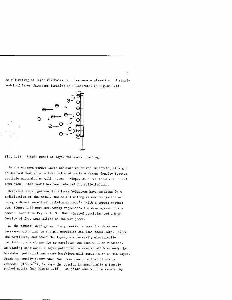
self-limiting of layer thickness requires some explanation. A simple
model of layer thickness limiting is illustrated in Figure 1.13.
o Z) 0-
©-
e—^ 0—^ e
.^
©F
+
0f 0f 8 +
Fig. 1.13 Simple model of layer thickness limiting.
As the charged powder layer accumulates on the substrate, it might
be assumed that at a certain value of surface charge density further
particle accumulation will cease simply as a result of electrical
repulsion. This model has been adopted for self-limiting.
Detailed investigations into layer behaviour have resulted in a
modification of the model, and self-limiting is now recognised as
being a direct result of back-ionization 11 With a corona charged
gun. Figure 1.14 more accurately represents the development of the
powder layer than Figure 1.13. Both charged particles and a high
density of free ions alight on the workpiece.
As the powder layer grows, the potential across its thickness
increases with time as charged particles and ions accumulate. Since
the particles, and hence the layer, are generally electrically
insulating, the charge due to particles and ions will be retained.
As coating continues, a layer potential is reached which exceeds the
breakdown potential and spark breakdown will occur in or on the layer.
Sparking usually occurs when the breakdown potential of air is
exceeded (3 Mv.m ), because the coating is essentially a loosely
packed matrix (see Figure 1.15). Bi-polar ions will be created by

22
0 - o © 0 - e
- e 0 ~_ 0
- ©
0 charged particles _ ions
Fig. 1.14 Powder layer growth using corona-charged gun.
o_ ©o - o -® P^
_1D_ Q
jsA^
vvy o- Q-
+^
Fig. 1.15 Back-ionization in powder layer.
23
each discharge and the negative charge will be collected by the sub-
strate, while the positive ions will drift away from the surface
towards the gun, under the action of the externally applied electric
field. This counter movement of positive ions immediately interacts
with the oncoming negative ions and negatively charged particles
resulting ultimately in neutralisation. Previously charged particles,
after neutralisation, will no longer be able to contribute to the
electrostatic deposition process, and thus coating ceases, correspond-
ing to the. familiar self-limiting of coating thickness, as a direct
result of the onset of back-ionization. That is, the onset at back-
ionization is associated with virtual cessation of charging of the
gun. 'With most commercial corona-charged gun systems, back-
ionization will commence once the first monolayer of powder has been
deposited on the workpiece. Investigations have shown that generally
back-ionization commences within about one second of trigger actua-
tion, primarily due to the high free ion density with externally
charged corona guns. Similar tests with tribo guns suggested a
typical coating time of 10 '\' 20 seconds before the onset of back-
ionization. Since no ions contribute to the potential build-up in
the deposited layer, it takes much longer for the breakdown potential
to be reached, relying entirely on the charge on the powder particles.
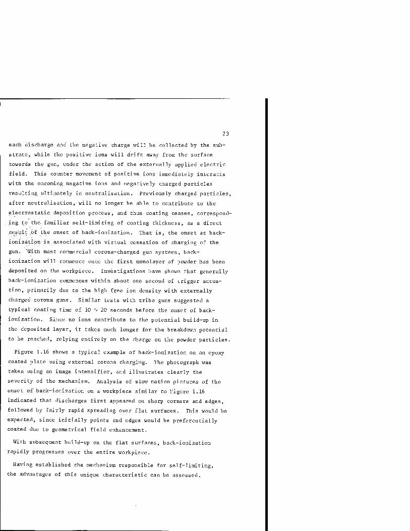
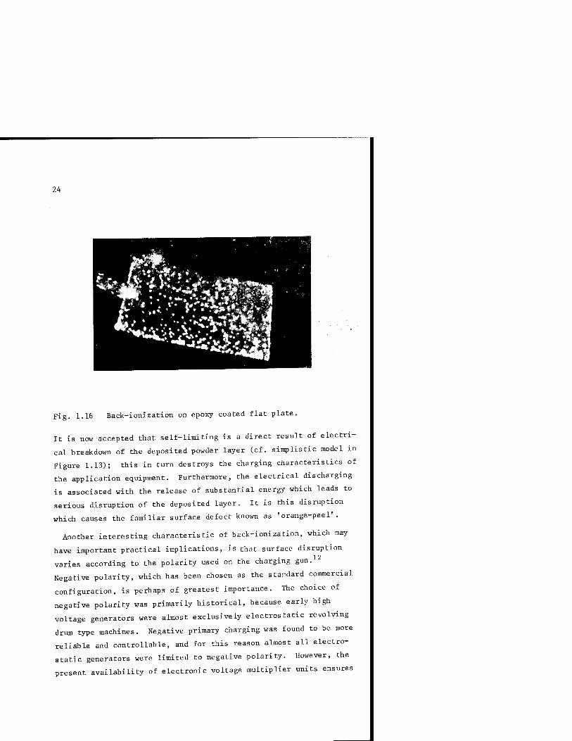
Figure 1.16 shows a typical example of back-ionization on an epoxy
coated plate using external corona charging. The photograph was
taken using an image intensifier, and illustrates clearly the
severity of the mechanism. Analysis of slow motion pictures of the
onset of back-ionization on a workpiece similar to Figure 1.16
indicated that discharges first appeared on sharp corners and edges,
followed by fairly rapid spreading over flat surfaces. This would be
expected, since initially points and edges would be preferentially
coated due to geometrical field enhancement.
With subsequent build-up on the flat surfaces, back-ionization
rapidly progresses over the entire workpiece.
Having established the mechanism responsible for self-limiting,
the advantages of this unique characteristic can be assessed.
24
Fig. 1.16 Back-ionization on epoxy coated flat plate.
It is now accepted that self-limiting is a direct result of electri-
cal breakdown of the deposited powder layer (cf. simplistic model in
Figure 1.13); this in turn destroys the charging characteristics of
the application equipment. Furthermore, the electrical discharging
is associated with the release of substantial energy which leads to
serious disruption of the deposited layer. It is this disruption
which causes the familiar surface defect known as 'orange-peel'.
Another interesting characteristic of back-ionization, which may
have important practical implications, is that surface disruption
varies according to the polarity used on the charging gun.
Negative polarity, which has been chosen as the standard commercial
configuration, is perhaps of greatest importance. The choice of
negative polarity was primarily historical, because early high
voltage generators were almost exclusively electrostatic revolving
drum type machines. Negative primary charging was found to be more
reliable and controllable, and for this reason almost all electro-
static generators were limited to negative polarity. However, the
present availability of electronic voltage multiplier units ensures

25
that polarity offers no limitations to design and performance.
With negative gun charging polarity, the spark associated with back-
ionization is a bulk phenomenon. That is, the spark channel actually
penetrates the depth of the deposited layer and can create the
familiar 'pin-holing', together with some degree of cratering which
is associated with 'orange-peeling'. On the other hand, when positive
corona charging is used, the nature of the back-ionization changes
considerably. The discharge does not penetrate the deposited layer,
but is more of a surface phenomenon. Using an image intensifier to
view positive back-ionization reveals a continuous surface glow,
rather than discrete point discharges associated with negative charg-
ing. There is no pin-holing, but the surface disruption usually
tends to be more severe. Spark energy measurements on both negative
and positive back-ionization indicates that negative sparks were
generally more energetic than positive, which probably accounts for
the ability of negative to penetrate the bulk of the layer.
Identification of important differences between positive and
negative charging involved sophisticated experimentation. For
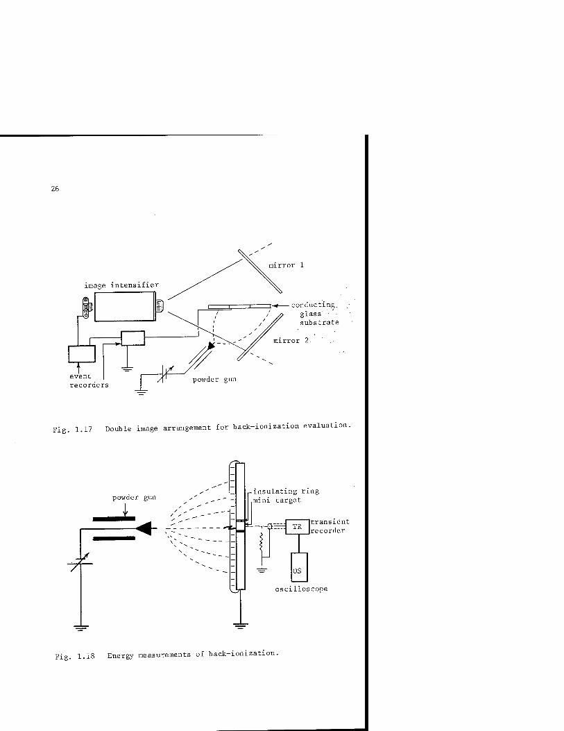
example, the system illustrated in Figure 1.17.was used to distinguish
between bulk and surface discharges.
A conducting transparent flat plate was coated on one side using a
standard commercial corona charging gun. The mirrors facilitated
simultaneous viewing of both the upper and lower powder layers, and
visual recording of the discharges was made possible by the use of an
image intensifier. Accurate matching of back-ionization sites was
achieved by comparing the images appearing in mirror Land mirror 2.
For negative charging, both images were matched indicating complete
puncturing of the layer; whereas for positive charging, discharge
sites appeared only in mirror 1 confirming the surface nature of the
spark.
Spark energy values were measured using a relatively complex tech-
nique: an experimental workpiece which incorporated a small electri-
cally isolated section, as shown in Figure 1.18. The diminutive size
of this section facilitated the isolation of single layer discharges.
26
mirror 1
]-« conducting, glass' substrate
mirror 2
event recorders
/I ' powder gun
Fig. 1.17 Double image arrangement for back-ionization evaluation.
powder gun
7f
insulating ring mini target
^i^. TR transient recorder
OS
oscilloscope
Fig. 1.18 Energy measurements of back-ionization.

27
In a system using a simple circuit and an oscilloscope, the appearance
of a discharge on the test electrode triggered the oscilloscope and
the energy associated with the charge transfer could be estimated.
These fundamental investigations suggested important practical
implications.
For example, when the surface finish is of prime importance, that is
the specification for the deposited powder layer is primarily aesthe-
tic,., negative powder charging may be the correct choice of polarity;
oratige'peel will be minimised, but pin holes may exist. However, with
the correct choice of powder offering adequate flow characteristics
during'curing, then most pin holes should be self-healing. On the
other hand, if the coating appearance is of secondary importance and
the prime objective is surface protection (automobile subframes and
internal coating) then positive powder charging might prove beneficial.
There may be widespread orange-peeling, but pin holing will be non-
existent and paint flow characteristics become of secondary importance.
The choice of gun charging polarity may thus be more important than
originally envisaged, both in terms of the type of coating required
and, as was discussed earlier, in the type of powder used in differ-
ent gun systems. For example, if a particular gun/powder combination
were to show negative tribo-characteristics, then negative corona
charging would be a logical choice of polarity; and conversely for
positive. This aspect of charging behaviour is now well known, and
some gun manufacturers now offer a choice of gun polarity.
It is generally accepted by experienced coaters that a tribo-charged
gun deposits a far superior quality coating than a corona charged gun.
Since no free ions are created by a tribo-gun, the charge build-up on
the deposited layer is entirely due to the charged particles. Thus,
the charge density in the layer is low and the layer breakdown poten-
tial will not be reached until a considerable thickness is achieved.
Tribo-charged coating tests have indicated that layer breakdown or
back-ionization may be initiated after about 10 seconds of coating
time. The corresponding value for corona charging is about one
second, or in most cases when the first monolayer of powder is

28
deposited.
Thus, with a tribo-charged gun, there is no back-ionization within
the first 10 seconds; and consequently there is no disruption of the
deposited layer which would lead to pin-holing and cratering. At the
same time, there is no self-limiting and very thick layers are
created; this is not a situation acceptable in most industrial
coating applications. However, this may be compensated by careful
control of conveyor speed and powder throughput.
Points of practical interest:
1. Corona-charged guns offer reasonably good control over powder
charging.
2. Tribo-charged guns offer little control over powder charging and
show erratic behaviour due to dependence on material and
environment.
3. Tribo guns are good for coating inside cavities.
4. Free ions are detrimental to coating finish.
Best compromise for practical system:
Use corona charging for powder, but eliminate free ions
emanating from gun head.
Powder application systems approaching this ideal requirement are
now commercially available. These systems will be described later,
together with a discussion of performance optimization.

29
CHAPTER 2 Measurement Techniques
Measurement of electrical parameters is , or should he, of paramount
importance to equipment manufacturers, powder manufacturers and users.
It is only hy accurate measurement and careful interpretation of the
results that any degree of system optimization can be achieved. Most
of the measurements are straightforward, provided certain precautions
are taken; while meaningful interpretation generally requires more
skill. For diagnostic purposes and system evaluation, it is usually
sufficient to measure just four electrical parameters. These are:
(i) Powder resistivity (p.fJm)
(ii) Powder charge-to-mass ratio (q/m C.kg )
(iii) Gun potential (V. volts)
(iv) Gun current (I. amperes)
Other parameters associated with complete system optimization and
coating booth evaluation are:
(i) Electric field (E. V.m"^)
(ii) Space potential (V. volts)
Knowledge of some or all these parameters will enable a fairly
accurate assessment of the performance of a coating system, including
identification of potential problems.
RESISTIVITY
In all applications requiring charging of particles, and subsequent
manipulation of their trajectories, a knowledge of the particles'

30
resistivity is essential and critical with regard to system behaviour.
A further complication is that for optimum coating behaviour in
corona charged systems, there is apparently no ideal or optimum value
of powder resistivity. In fact, any attempt at optimization
necessitates a compromise in terms of resistivity as implied in the
preceding chapter. At the gun head, the lowest possible resistivity
is necessary to achieve efficient particle charging; once charging
has been completed, the highest possible resistivity ensures that
when the particle alights on the workpiece charge relaxation will be.
slow and good adhesive properties will be assured. Such a compromis;e .
situation exists in many electrophotographic image copying mechanisms,
where the ink.toner particles need to be as conducting as possible at
the development stage (toner transfer onto latent image on the photo-
conductor) ; but for the remainder of their duty cycle, should be as
insulating as possible for good adhesion and transfer to the paper.
Some toners achieve this compromise resistivity through a number of
inspired innovations associated with formulation. Some toners display
variable resistivity characteristics, with electrical properties
changing according to pressure or electric field. To achieve this
variability toner formulations are in general chemically complex and
a similar approach is not thought to be feasible with powder paint.
Currently the choice of material resistivity is limited. Most of
the common materials such as epoxy, polyester, acrylic, nylon,
polyethylene, etc. are inherently highly resistive (usually > lol"* Qm)
and potentially display excellent adhesive properties. Efficient
charging of such materials, however, is not straightforward (see
Chapter 1). In terms of acceptable adhesion, then the lower limit of
powder resistivity is approximately 10^2 am. Below this value,
charging will be good but adhesion will be poor. Apart from adhesion
problems with low resistivity powder, an important gain in coating
finish will be achieved. Since charge relaxation will be rapid, the
potential required across the coating thickness to initiate back-
ionization will never be reached, hence no pin-holing or cratering
will occur - even with high free ionic density. This should perhaps
be considered in electrostatic systems using pre-heated workpieces.

31
where electrostatic adhesion is of secondary importance.
A number of methods have been developed for the measurement of
powder resistivity. One of the simplest and perhaps most widely used
methods is the bulk resistivity cell technique. A typical cell
arrangement is illustrated schematically in Figure 2.1. The powder
sample is poured into the cell and subjected to a steady d.c.
potential (V), while the current (I) flowing in the external circuit
is monitored.
■•'V The", powder resistance (R) can be calculated from the Ohm's Law
relationship:
I
Knowing cell electrode dimensions and spacing, the specific resis-
tance, or resistivity, can be calculated using:
Resistivity R - n.m
where a = electrode area (sq. m)
I = electrode spacing (m)
guard electrode
Fig. 2.1 Schematic of powder resistivity test cell.
32
This method is apparently simple but caution must be exercised,
however, with respect to both the method adopted for data recording
and the interpretation of the calculated parameter. For example,
when a powder sample is poured into the cell, the possible effect of
packing density on the conduction current must be considered. Should
the powder be allowed to settle normally under gravity, or should a
standard compression be applied to the sample surface? Numerous
tests have been carried out on this type of test cell, and for the
powder samples tested the application of pressure appeared to have a
minimal effect on conduction. As long as the powder was allowed to
settle normally into the test cell, by gently tapping its base on a
bench top, then measurement of conduction current was reproducible.
Of more interest, perhaps, is the actual construction of the test
cell and the material chosen for its fabrication. The cell must
itself be electrically insulating, but as many of the powder samples
themselves are highly insulating (> lol"* fi .m) , it is possible that
the sample resistivity could exceed the cell resistivity. Under
such conditions, when the current is monitored, and hence the resis-
tivity calculated, the value obtained may well relate to the cell
rather than the sample it contains. This problem could be largely
overcome by incorporating a guard electrode into the cell wall, as
illustrated in Figure 2.1. Any surface conduction component of
current along either the inside or outside cell wall will be inter-
cepted by the guard electrode and diverted to ground. The current
(I) measured in the external circuit will therefore be entirely due
to charge that has traversed the cell through the powder between the
electrodes. Guard electrodes are essential if meaningful resistivity
values are required, and careful cell preparation should precede all
measurements. For example, both the inside and outside surfaces of
the test cell should be thoroughly degreased in order to minimise
surface conduction; and cells should be rigorously cleaned between
sample loading.
When using this type of resistivity test cell, it is very common
to observe a slow but steady decline in the current after application
of the external voltage. This is especially noticeable when
33
conducting measurements on highly resistive powders. In some cases
it can take up to 10 '^ 15 minutes before a steady current value is
displayed. This effect is primarily due to polarization effects in
the powder, with reorientation of dipoles occurring as a result of
the application of a step voltage. As different species of dipoles
re-orientate at different rates, the apparent initial high value of
conductivity is extended over a period of time. When a steady conduc-
tion current is reached, then polarization will have been completely
relaxed and the remaining current will be entirely due to charge
conduction mechanisms in the powder sample itself. It is important,
therefore, when performing resistivity measurements, to allow suffi-
cient time for relaxation of the polarization mechanisms. Generally
a 10 minute pause after the application of voltage is recommended
before noting the value of the current.
More sophisticated powder resistivity meters are now available
commercially, with direct readout of resistivity and autoranging
facilities. The precautions mentioned previously apply to these
types of instruments. With direct read-out of resistivity, then the
initial reading will be low, gradually increasing to a steady value
after the 10 minute relaxation period. A useful pre-check on these
instruments is to note the resistivity of the empty cell. This
should indicate either infinity, or the maximum range of the
instrument. Any deterioration in cleanliness due to careless handl-
ing or inadequate laboratory techniques will be identified easily
using the precheck; while reinforcing credibility in the accuracy of
powder sample measurement.
Figure 2.2 illustrates a typical direct read-out powder resistivity
meter. Considerable design improvements have been incorporated into
this instrument; for example, the test cell itself bears little
resemblance to the schematic shown in Figure 2.1.
To facilitate the cleaning of the test cell, the electrodes are
an integral part of the cell wall, while still retaining the essen-
tial guard ring electrode. The electrodes are mounted in a horizon-
tal plane, and the internal volume of the test cell reduced to a few

34
Fig. 2.2 Powder resistivity test meter. (courtesy Wolfson Electrostatics Unit)
cubic centimetres. Easy cleaning is further enhanced by the unique
'splitting-cell' feature, which also greatly simplifies cell loading.
An alternative method of measuring powder resistivity adopts a non-
contact charge decay measurement.^^ This method is especially useful
if only a small sample of powder is available, or if measurements
have to be made on a sample already applied to a substrate. The
method involves measurement of the electric field associated with an
electrically charged layer of powder, as shown schematically in
Figure 2.3.
Details of the field-measuring device, or field mill, will be
discussed later.
The charge on the powder may be that due to the normal gun charging,
or the powder may be deposited by some other means, and the layer
later charged using a uni-polar corona source. At the end of charging,

35
Field mill
charged powder layer
Fig. 2.3 Electric field measurement on charged powder layer.
the charge, and thus the electric field associated with it, will
decay according to the relationship:
E = E exp E E p or
(4)
— 12 —1 where E = permittivity of free space (8.854 x 10 F.m ).
E = relative permittivity of powder.
p = volume resistivity of powder.
This exponential decay will have the general shape indicated in
Figure 2.4.
The time constant, T, from equation (4) will be given by:
T = e e p or (5)
So measurement of T from the decay curve, and knowing E will allow
calculation of p. If e^, the relative permittivity of the powder, is
not known, then an additional measurement will be necessary. A
capacitance measuring device, or bridge, will be required for this

36
Time. T
Fig. 2.4 A typical exponential decay plot of electric field versus time.
measurement which usually involves two measurements of capacitance.
An air filled capacitor is first measured on the bridge.
Let this be
A e
where A = capacitor plate area.
d = capacitor plate separation.
The air space between the capacitor plates is then filled with the
sample powder, and a second value of capacitance measured using
the bridge.
Let this be
A e e o r = e C
r o
Hence e , the relative permittivity of the powder, will simply be: '^ C
r (6) r C o

So, from equation (5);
Volume resistivity p
e e o r
T C
e C o r
37
(7)
Thus, the value for volume resistivity is obtained by a more complex
procedure than the direct read-out resistivity test cell.
INTERPRETATION
In the present discussion, the resistivity parameter for powder has
been referred to as volume resistivity (S.I. units of fi.m). This may
seem reasonable as it is assumed that, in the resistivity test cell,
the charge conduction is actually through the bulk of powder sample.
Likewise, using the charge decay model, it is assumed that charge
conduction is through the bulk of the deposited layer towards the
earthed substrate. This basic assumption justifies further
discussion.
The powder sample in the test cell may appear as shown in Figure
2.5, when enlarged several hundred times.
(a) (b)
Fig. 2.5 Charge conduction paths in packed powder sample,
(a) Surface conduction; (b) Bulk conduction.

38
If the current, I , measured in the external circuit is due to
bulk conduction through the powder particles, the conduction paths
might resemble those shown in Figure 2.5(b). However, if the powder
is electrically insulating, it is difficult to imagine that the pre-
ferred path for charge migration will be through each powder particle.
Under these conditions, a more realistic conduction path might be as
depicted in Figure 2.5(a), where charge migration is essentially
following the surface contours of each particle. In that case, the •■
current measured in the external circuit, I , will be representative
of a surface rather than a bulk characteristic. For this reason,
there will always be a certain degree of uncertainty in the inter-
pretation of bulk resistivity of powders measured in this way,
especially when the units of resistivity, ohm metres, are used to
define what may be a surface effect. If conduction is a surface
phenomenon, then the parameter will be resistance rather than
resistivity, and the units will be ohms.
For highly insulating powders, this anomaly will always be present,
and care should therefore be exercised when absolute values of bulk
resistivity are required. For day-to-day comparative measurements,
the resistivity test cells serve a useful purpose, provided the user
is aware of the limitation.
The difference between bulk or volume resistivity, and surface
resistance should perhaps be further clarified here. Resistivity, or
specific resistance, was defined earlier.
The relationship p = R y accommodates the bulk of the sample
between the cell electrodes. If conduction is a surface phenomenon,
then volume cannot be accommodated into the above relationship, and
thus the often-quoted parameter, surface resistivity, cannot be
meaningful. A standardised method of measuring surface conduction is
illustrated schematically in Figure 2.6.
Two straight electrodes of length, I, are placed on the surface of
the material under test, and spaced a distance, I, apart. With a
voltage, V, applied to one electrode; a current, I, will be measured

39
-7
■O-i
Fig. 2.5 Method for measuring surface resistance.
as shown. The surface conduction characteristic of the material
will then be that of surface resistance in ohms. By using the
square (£x!l) electrode configuration , normalisation of the
parameter produces a new unit for surface conduction, that of ohms
per square (H/Q). Thus, surface resistance differs from bulk
resistivity; Table 1 emphasises the important difference between
these two parameters.
TABLE 1. Surface and bulk conduction parameters.
Parameter Units
Surface conduction
Surface resistance
n /□
Bulk or volume conduction
Bulk or volume resistivity
n . m

40
CHARGE-TO-MASS RATIO (q/m)
A measure of the ratio of particle charge to particle mass is a
useful indication of how well the particle has been charged. There
is a theoretical limit to the charge a particle can accommodate,
(see the Pauthenier limit).
Measurement of q/m is very useful in practice as it immediately
gives an indication of how well a particular gun system is working,
which in turn may be used to assess the coating efficiency of a
particular plant.
In its simplest embodiment, measurement of q/m is relatively easy
to do; but as will be seen later, certain precautions have to be
taken with most gun systems, and as with resistivity measurements
the data obtained must be carefully interpreted. In order to mea-
sure the charge-to-mass ratio of a powder sample, two measurements
are required. First, the charge on the powder, and secondly the
mass of the powder sample. It is convenient to contain the powder
sample in order to measure the mass, and for this reason the most
suitable method of measuring charge is by means of a Faraday cup
arrangement. A simple Faraday cup is illustrated in Figure 2.7.
As charged powder enters the cup, an equal and opposite charge flows
from earth to electrically balance the charge residing in or on the
cup. This charge will be measured on the electrometer, and will be
equal to the total charge associated with the powder in the cup.
The cup itself is usually accommodated inside another cup which is
itself connected to earth. This outer cup, or screen, ensures that
no induced charges are created on the measurement cup from some
external source; that is, with screening, the induced charge on the
inner cup will be that solely due to the charged powder entering it.
If the openings on the face of the cup and screen are small com-
pared to the overall area of the face, penetration of electric field

41
lines from an external source should be minimal. Following the mea-
surement of charge, the inner cup may be removed from the screen, and
the mass of collected powder measured. The total charge on the
electrometer, divided by the total mass of powder in the cup, will
then give the value of charge-to-mass ratio (q/m in Coulombs per
kilogram. C/kg).
The difficulties associated with interpretation of this measurement
arise when powder samples emanating from a corona charged gun are
collected. Three species of particles travel between gun and work-
piece (see Chapter 1); charged powder particles, uncharged powder
particles and unattached free ions. If the Faraday cup arrangement
is situated so as to intercept the powder flow from a gun, all three
species will be collected by the cup. Since the free ion component
of charge will normally be a few orders of magnitude in excess of the
net particle charge, it is clear that the charge measured on the
electrometer in the external circuit will be erroneously high and
bear no resemblance to the true charge associated with the particles
alone. Also, since both uncharged and charged particles will be
collected by the cup, the mass of powder weighed at the end of the
test will also be erroneously high and will not be representative of
the mass associated with the charged particles. In order to rectify
these measurement difficulties, certain modification have to be
incorporated into the simple Faraday cup arrangement illustrated in
Figure 2.7.
Considering first the ionic component of charge, some method must
be devised for capturing the free ions before they enter the inner
Faraday cup. One approach adopts a metal screen mesh placed over the
input port of the cup arrangement. With the correct choice of mesh
size, it can be arranged that all the ions are captured by the mesh,
while particles will be transmitted and collected by the Faraday cup.
This separation of ions and particles relies primarily on the much
higher mobility of the ions compared to the particles, with the
momentum of the particles essentially conveying them through the mesh
and into the cup. This ion/particle separation is illustrated
schematically in Figure 2.8.
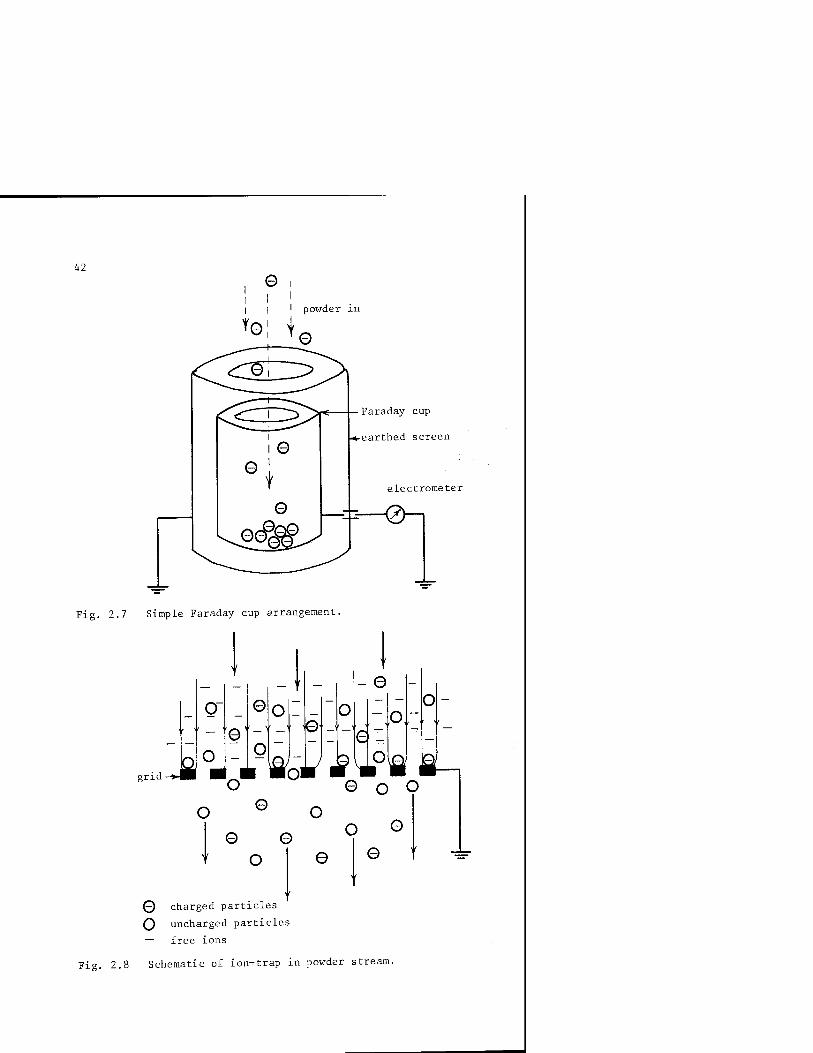
42
I I I powder m
rel Y
Faraday cup
earthed screen
electrometer
■;-—0-1
Fig. 2.7 Simple Faraday cup arrangement.
grid Ja
Q
o
o
e
-1 0
O MoM
o o
,o o
0 o 0 0
o
0 o Q
O 0 0
0 charged particles
O uncharged particles
— free ions
Fig. 2.8 Schematic of ion-trap in powder stream.

43
Although apparently satisfactory in theory, in practice the mesh
itself rapidly becomes coated with powder and back-ionization will be
initiated within about 1 second of the measurement. The result is
that the charge on further oncoming powder is rapidly modified and the
net charge measured on the electrometer will be erroneous and unrepre-
sentative of the charging characteristics of the gun. The problem of
uncharged powder particles entering the Faraday cup still persists.
For the mesh ion-trap to be effective, therefore, powder accumula-
tion on the mesh itself must be avoided. A method in which this has
been achieved very effectively involves incorporating an irrigated
mesh arrangement to the charge-to-mass measuring device.'^'^ This device
also facilitates the separation of the charged and uncharged powder
particles. A schematic of the arrangement is shown in Figure 2.9.
water 'in'
powder catcher
base manifold
water ' out' .<.
Fig. 2.9 Irrigated grid device for absolute measurement of q/m.
In one particular arrangement the grid wires were spaced approxi-
mately 10 mm apart. A manifold arrangement allowed the surface of
all the vertical wire strands to be wetted and continually washed.

44
Behind the irrigated mesh, the familiar Faraday cup has been re-
placed by an L-shaped powder catcher. The vertical and horizontal
sections may be electrically isolated and connected to earth via two
separate electrometers, as shown in Figure 2.9; or they may be
electrically connected and grounded through one electrometer. The
implications of this arrangement will be explained later.
It is the continuous irrigation of the grid which prevents powder
accumulation on the grid wires. Charged powder particles will still
be attracted to, and impinge on, the wet earthed wires, but the down-
ward motion of the water film prevents adhesion of the particle at "the
point of impact. Instead, the particles are flushed down into the
base manifold where they are allowed to accumulate and the return wa-
ter flow drains out of the system. All the ions are similarly trapped
by the irrigated grid, and are immediately neutralised to earth.
At the irrigated grid, therefore, the first step in particle
species separation has been achieved. The ions are removed without
the creation of a secondary problem associated with grid back-
ionization, and the charge measurement on the powder collecting
plate will be that solely due to charge on the particles. In order
to ensure the validity of this ion-capture technique, a number of
comprehensive evaluations were necessary. For example, would the
grid preferentially capture the most highly charged particles - thus
effectively removing a 'cut' in the powder sample? Would the water
disrupt off the surface of the wires when subjected to a high
electric field? Careful evaluation under many different experimental
conditions has indicated that such effects are minimal, and that the
charge measured on the collecting plates is representative of the
powder charging characteristics of the gun.
Having achieved separation of the ions without back-ionization,
then the charged powder particles must be separated from the un-
charged powder particles. This is not essential, and depends
largely on the required characteristic of the gun., For example, if
both charged and uncharged particles are collected and included in
the q/m measurement, that will be a measure of the mean charge-to-
mass ratio. If only the charged particles are collected and included
in the measurement, a measure of the maximum charge-to-mass ratio
45
will be achieved. It is debatable which approach yields the most
useful or meaningful result, and this, in turn, depends to a large
extent on the objective of the test. For example, if data are
required for the overall system performance, an indication of the
mean q/m might be most important. On the other hand, using the
L-shaped powder catcher enables a comparison to be made of the pro-
portion of charged to uncharged powder, a useful measurement if gun
charging efficiency is being evaluated.
This latter measurement is made possible by the split electrode
facility as illustrated in Figure 2.9. Q[ will be a measure of the
charge associated only with particles that are sufficiently charged
to ensure adhesion on the vertical face of the L-section electrode.
Insufficiently charged, and uncharged, particles will alight and be
collected on the horizontal face. The very low charge associated
with this sample will be measured as QT. Charge-to-mass ratio
calculated from Q, and the vertical face only will be a measure of
the maximum q/m. Charge-to-mass ratio calculated from (Q| + Q2) and
the sum of the powder mass from the vertical and horizontal faces
will be measure of the mean q/m. Finally, comparison of powder mass
on the vertical and horizontal faces will give an indication of gun
charging efficiency.
It would appear, therefore, that the irrigated grid method of
measuring q/m is versatile both in terms of producing useful measure-
ments and, for the first time, eliminating the detrimental effects of
back-ionization. The measurement of absolute values of q/m is now
possible for corona-charged guns.
This does not mean, however, that the more conventional grid-
protected Faraday cup arrangement cannot be used; only that
considerable care has to be exercised in its use and interpretation
of results. A commercial version of this system is illustrated in
Figure 2.10, where charge-to-mass ratio is just one function in a
powder coating test set.
The precautions necessary when using this type of test cell
include:
(i) Awareness that the parameter measured will represent a mean
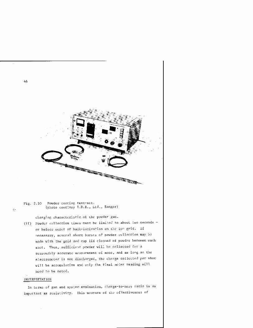
46
Fig. 2.10 Powder coating test-set. (photo courtesy I.D.B., Ltd., Bangor)
charging characteristic of the powder gun.
(ii) Powder collection times must be limited to about two seconds -
or before onset of back-ionization on the ion grid. If
necessary, several short bursts of powder collection may be
made with the grid and cup lid cleaned of powder between each
shot. Thus, sufficient powder will be collected for a
reasonably accurate measurement of mass, and as long as the
electrometer is not discharged, the charge collected per shot
will be accumulative and only the final meter reading will
need to be noted.
INTERPRETATION
In terms of gun and system evaluation, charge-to-mass ratio is as
important as resistivity. This measure of the effectiveness of
47
powder charge, and the percentage of the total gun powder which is
charged, gives a good indication of the expected performance of a
gun system. In Chapter 1 an approximate value of the maximum q/m in -3 -1
a typical corona-charged gun is given as 10 C.kg . In practice,
this degree of charging results in exceptionally good particle adhe-
sion, and a charge-to-mass ratio of 10 C.kg would be adequate.
Generally, it is not difficult to achieve a high mean value of q/m,
but what is more difficult and indeed considered more important, is
to achieve a high charging efficiency. That is, what proportion of
the total number of particles emanating from the gun are charged
sufficiently to display adequate adhesion characteristics? The
split L-shaped electrode in conjunction with the irrigated grid
allows this important measurement to be made. This measurement
should not be confused with the more straightforward charge-to-mass
ratio.
GUN POTENTIAL AMD CURRENT
The instrument illustrated in Figure 2.10 allows easy measurement
of both gun voltage and current. In a corona-charged system, these
are important parameters, which enable the operator to maintain either
spot or continuous checks on the electrical supply to the gun. It
should be stressed, however, that system behaviour cannot be assessed
accurately from voltage (V) and current (I) alone. What may be
considered as adequate gun voltage and current may not necessarily
correspond to adequate gun performance. It is incorrect to assume
that when a high gun voltage and current is indicated a high charging
efficiency is guaranteed, leading to a high coating efficiency. In
many instances, the reverse is true; the reason for this will be
explained later.
Most commercial gun systems will have a voltage indicator located
on the front panel of the control console. This voltage will be an
indication of the output voltage of the high-voltage supply.
Although commonly employed by equipment manufacturers, it is not the
ideal method if voltage indication is to be used as a useful parame-
ter in setting up a system for optimum performance. The important

48
voltage is the gun head voltage, i.e. that of the charging electrode
itself; and this value could differ considerably from the output
voltage of the high-voltage generator. In the extreme case, for
example, there could be a break in the high voltage line between the
gun head and voltage generator. The voltmeter on the control console
would still indicate normal output voltage; however, the actual
voltage at the gun head would be zero, resulting in complete loss of
corona charging. An extreme situation, perhaps, but nevertheless
one which could easily lead to a frustrating and time-consuming fault-
finding exercise. A break of this type in the high-voltage line need
not result in a drop or loss of indicated gun current, as the severed
connection may well itself go into corona, albeit at a position
remote from the gun nozzle and thus not contributing to powder
charging.
A less extreme situation exists with this method of voltage indica-
tion under more normal gun operation. The high voltage leads on most
commercial guns will incorporate a high resistance in series with its
connection to the output of the high-voltage generator. This acts
primarily as a current limiter and safety device in the event of the
operator accidentally contacting the charging electrode while the
gun is operational, or that the gun head sparks over to an earthed
object, thus creating a potentially incendive situation. With such
a resistive load, and with current flowing through the gun charging
circuit, there will be a substantial voltage drop between the output
of the generator and gun head. In that case, the voltage indicated
on the control console will be quite different to the voltage at the
charging electrode.
For example, consider a typical commercial gun system with a resis-
tive load of 500 m in the high voltage cable. Assume the output
voltage of the high voltage generator indicates 70 kV, and that the
gun current was 30 x 10~^ Amps. This would represent a voltage drop
of about 15 kV along the length of the cable, with the resulting
voltage at the head of the gun therefore being 55 kV and not 70 kV
as indicated. The implications of this voltage drop may not be
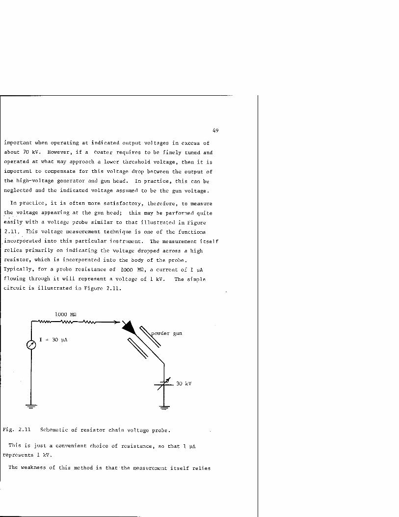
49
important when operating at indicated output voltages in excess of
about 70 kV. However, if a coater requires to be finely tuned and
operated at what may approach a lower threshold voltage, then it is
important to compensate for this voltage drop between the output of
the high-voltage generator and gun head. In practice, this can be
neglected and the indicated voltage assumed to be the gun voltage.
In practice, it is often more satisfactory, therefore, to measure
the voltage appearing at the gun head; this may be performed quite
easily with a voltage probe similar to that illustrated in Figure
2.11. This voltage measurement technique is one of the functions
incorporated into this particular instrument. The measurement itself
relies primarily on indicating the voltage dropped across a high
resistor, which is incorporated into the body of the probe.
Typically, for a probe resistance of 1000 Mfl, a current of 1 yA
flowing through it will represent a voltage of 1 kV. The simple
circuit is illustrated in Figure 2.11.
1000 Mfi
owder gun
0 I = 30 uA
30 kV
Fig. 2.11 Schematic of resistor chain voltage probe.
This is just a convenient choice of resistance, so that 1 yA
represents 1 kV.
The weakness of this method is that the measurement itself relies

50
on current flowing through the resistor chain; that is, the measure-
ment loads the high-voltage generator connected- to the gun, and may
interfere with the current capability of the device. So, in a situa-
tion where the gun may be operating at or near the current limit of
the generator, the use of this type of probe will change the overall
gun charging characteristics. A more satisfactory method for measur-
ing voltage is to use a non-interfering voltage probe, and a number
of commercial instruments are available which offer this capability.
One type is shown in Figure 2.12. Here the upper electrode is
connected directly to the high voltage to be measured. Due to its
geometry, it will not support a corona discharge, and the only
current corresponds to the charge transferring to the measuring
sphere. Once the sphere has attained the potential of the gun
electrode, no further current will flow. The actual potential is
calculated from a measure of the electric field associated with the
charge on this upper electrode. The electric field is measured by
means of a field mill (see later in this chapter) incorporated into
the lower electrode of the measuring voltmeter.
Although slightly cumbersome, and perhaps not quite as accurate as
the resistor chain method for measuring voltage, this instrument does
nevertheless offer the advantage of zero current drain - an important
consideration when measuring voltages on current limited circuits.
Both the probe and field techniques are polarity sensitive.
INTERPRETATION:
In powder application equipment, a knowledge of both charging
current and voltage is essential if any degree of system optimization
is sought. Contrary to general belief, the current is a more
important and crucial parameter for optimum performance. Without
sufficient charge being created at the gun head, particle charging
efficiency will be correspondingly low. As was discussed earlier
(Chapter 1), efficient ionic attachment to individual particles is
not easy to achieve, hence the requirement to generate a dispropor-
tionately high charge density ion cloud in order to achieve, at best,
a charging efficiency of about 60%. The penalties of creating such a

51
Fig. 2.12 Electrostatic voltmeter. (Courtesy I.D.B., Ltd.)
high free ion cloud have already been discussed with regard to onset
of back-ionization and its implications. In most conventional pistol
applicators, a relatively high voltage is required to generate this
high charge density ion cloud. This arises primarily from the fact
that the entire gun voltage is dropped between the gun head and work-
piece - a distance which typically may be about 1 metre. To achieve
a sufficiently high intensified field for corona onset at the charg-
ing electrode, therefore, a correspondingly high voltage is required.

52
If E
V
d
Then
= Electric field (V m )
= Voltage (V)
= Gun/workpiece spacing (m)
E =
So with large d, V must also be large to achieve large E.
The high voltage was originally thought to be important, not just
for the creation of the corona discharge, but also to realise the
familiar electrostatic coating model of particles following electric
field lines; this has since been disproved. Air flow appears to
dominate in terms of conveying particles to close proximity of an
earthed workpiece, and some tests have clearly indicated that a more
even wrap-around is achieved with the workpiece actually in a field-
free region.15 So, in some respects a high voltage on an externally
charged corona gun is not necessarily conducive to good performance.
Consider the implications of high gun voltage:
TABLE 2. Effects of higher gun voltage. (Externally charged corona).
Higher gun voltage, leading to higher gun current.
Advantages Disadvantages
Possibly increases charging efficiency at gun head.
Enhanced back- ionization. Wrap-around deteriorates. Poor penetration.
Table 2 clearly shows that the disadvantages far outweigh the
advantages of increasing gun current by means of a higher gun voltage.
Both wrap-around and penetration suffer as a direct result of
particles attempting to follow lines of electric field. That is,
there will be preferential coating initially on areas of the work-
piece with the smaller radius of curvature, while no field lines will
penetrate corners and cavities resulting in poor penetration.

53
It would appear, therefore, that in this type of externally charged
corona application equipment, a further compromise must be sought for
optimum performance. In addition to a compromise choice of powder
resistivity, the voltage/current combination must also be carefully
chosen. The voltage must be sufficiently high for the creation of a
corona discharge, but not so high as to adversely affect the particle
trajectories between gun and workpiece.
It is difficult, and indeed impossible, to quote definite values
for optimum voltages and currents. The performance of each indivi-
dual system will depend on so many variables; these include:
The type of gun used.
Powder. Particle size distribution.
Powder resistivity.
Shape of workpiece.
Distance between gun and workpiece.
Current capability of gun high-voltage generator.
However, a general guide to improved operating procedure might
include the following points on a simple check-list:
1. Without powder flowing through the gun, check gun current for
various gun voltages.
2. Observe drop in gun current with powder flowing through gun.
3. Observe variation in gun voltage and current with spacing
between gun and workpiece.
4. Note difference in deposition characteristics with different
shaped workpieces.
In order to gain any benefit from the above setting-up procedure,
measurement of charge-to-mass ratio will be necessary as discussed -4 -1
earlier. A charge-to-mass ratio of at least 10 C.kg must be
achieved if acceptable coating behaviour is expected. The combined
effects of gun voltage and current will be found to be crucial,
especially for complex-shaped workpieces that have many sharp corners,
edges and points, and deep cavities. Rounded geometries and smooth

54
surfaces will accommodate a much wider range of gun voltage/current
before deterioration of the coating performance and quality becomes
evident. The more complex the geometry of the workpiece, therefore,
the more difficult it will be to arrive at a compromise operating
set-up.
Under normal operating conditions, there would appear to be a great
temptation to increase both gun voltage and powder feed rate in an
attempt to improve particle deposition; this would have quite the
opposite effect. Increasing gun voltage will generally increase gun
current which will in turn enhance back-ionization, leading to a
deterioration in deposition. Likewise, increasing powder feed rate
will decrease gun current,, resulting in an overall decrease in
charging efficiency.
Some measurements, combined with observation of coating behaviour,
should ensure acceptable performance. First, measure q/m, gun cur-
rent and voltage, then proceed with visual assessment. At least the
initial measurements will identify a starting point from which 'fine
tuning' of the system may be performed subsequently in order to
achieve optimum performance.
ELECTRIC FIELD
It is often desirable to have some knowledge of the value of the
electric field that exists within a coating booth, especially at
regions near the booth walls, as this will be one of the high field
regions and be responsible for conditions most likely to detract
from good system performance.
Measurement of electric field is reasonably straightforward, and
a variety of commercial equipment is readily available. One of the
most common, and perhaps most robust, instruments is the field mill.
One type of field mill is illustrated in Figure 2.13.
In its simplest form, this type of instrument basically measures
the voltage due to induced charge on a sensor electrode. Usually
two sets of sensors are incorporated into the measuring head, with a
rotating vane electrode arranged so that the static sensors are

55
alternately screened from and exposed to the region of charge to be
measured. In this way, a square wave is produced which is subse-
quently amplified and processed in such a way as to give an output
signal representative of the electric field at the sensor head.
Most instruments of this type are polarity sensitive, and are
available with a varying degree of sophistication. For example, a
hand-held version of the instrument is usually quite adequate for
rough assessment of electric field, while a more precise instru-
ment similar to that shown in Figure 2.13 would be required for
accurate data recording. Specialised instruments allow field mea-
surements to be made in adverse environments; for example, in a
dusty or wet environment, or In a location which may be potentially
incendive.
Fig. 2.13 Rotating vane type field mill. (Courtesy X.D.B. Ltd.)
56
Other types of field measuring instruments include a vibrating reed
sensing head, and a radio-active detector. The measurement of elec-
tric field is probably the best served of all electrical parameters
in terms of the availability and variety of commercial instruments.
INTERPRETATION:
As with all measurements, some care must be exercised both in the
execution of the measurement itself and in its interpretation.
In many powder coating applications, it is necessary to measure
electric field in what is invariably a very dusty environment. The
correct choice of instrument is therefore crucial. If the instru-
ment is to be used in a powder coating booth, for example, then the
first consideration must be the safety aspect, and the instrument
should be certified as safe for use in an incendive environment .
Since most sensing heads are fabricated of metal and are normally
earthed, insertion into a powder booth will result in rapid coating
of the head including the rotating vane sensor. This invariably
leads to erroneous readings, with eventual seizing up of the vane
drive motor. Under such conditions, therefore, it is essential to
ensure that the sensing head is continuously purged thus preventing
particulate collection. Some commercial field mills are offered
with purging facilities as standard equipment. Others may have to
be modified according to requirements. A simple method of achieving
quite efficient head cleaning is illustrated in Figure 2.14. This
is a well tried technique for use in powder storage silos 1^, and has
been used successfully over an extended period in large silos.
The small air jets directed onto the surface of the sensing head
ensure that no particles alight on the vanes.
As with all field mill measurements, caution must be exercised in
locating the sensing head in order to record a meaningful value of
electric field. Typical of most electrical measurements, the
existence of the instruments affects and modifies the environment in
which the measurement is being made. This problem is very evident
when using the field mill. Imagine, for example, using the field-
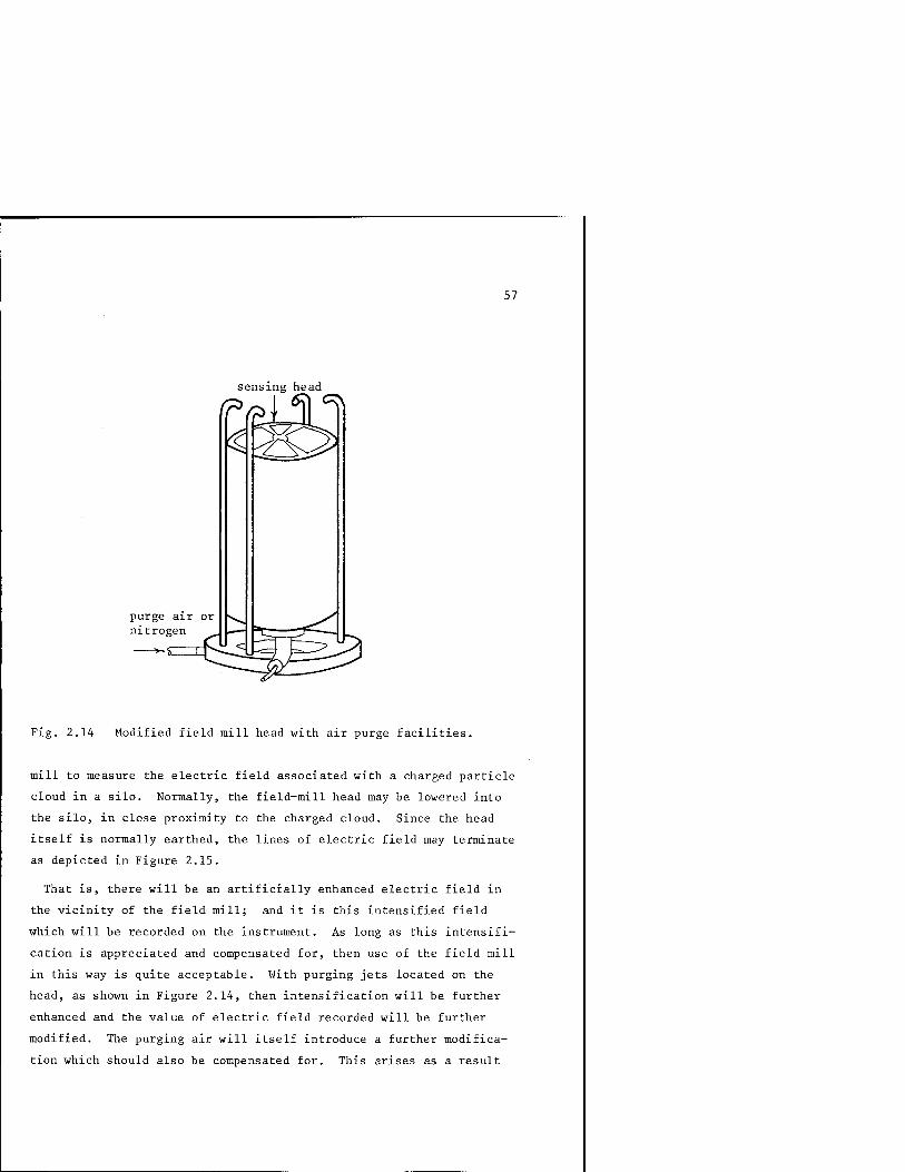
57
sensing head
IP ^ \ (^ (^
purge air or nitrogen
Fig. 2.14 Modified field mill head with air purge facilities.
mill to measure the electric field associated with a charged particle
cloud in a silo. Normally, the field-mill head may be lowered into
the silo, in close proximity to the charged cloud. Since the head
itself is normally earthed, the lines of electric field may terminate
as depicted in Figure 2.15.
That is, there will be an artificially enhanced electric field in
the vicinity of the field mill; and it is this intensified field
which will be recorded on the instrument. As long as this intensifi-
cation is appreciated and compensated for, then use of the field mill
in this way is quite acceptable. With purging jets located on the
head, as shown in Figure 2.14, then intensification will be further
enhanced and the value of electric field recorded will be further
modified. The purging air will itself introduce a further modifica-
tion which should also be compensated for. This arises as a result

58
field mill head
field intensification
Fig. 2.15 Field intensification due to presence of field mill in charged cloud.
of the air blast disrupting the charged powder cloud in close
proximity to the measuring head. Special care should therefore be
exercised when purging is used.
A better way of using the field mill to measure electric field is
to ensure that, whenever possible, the plane of the segmented elec-
trode is parallel with and surrounded by a large flat guard electrode.
This may be achieved relatively easily in a silo by installing the
head flush with a side wall - the silo wall itself acting as a guard
electrode. The electric field thus measured will be a true uninten-
sified value of the field at the silo wall. If purging is limited
to low air velocities, this measurement may approach an absolute
value for electric field.
In hand-held field mills, this guarding or shielding of the head
will be more difficult to achieve. However, some instruments are
supplied with a small screw-on shield which certainly helps with
reducing the error due to field intensification.
For powder coating applications, field mills or field detectors are
useful instruments for rapid assessment of coating system behaviour,

59
for example one application is illustrated in Figure 2.3, where a
field mill is used to measure the resistivity of- a deposited layer of
powder. Charge build-up on the booth walls may be assessed easily,
and some indication of gun charging behaviour may be achieved simply
by noting the field associated with the powder cloud emanating from
the gun nozzle. This latter measurement is easier to interpret when
used with tribo or egd-type guns, otherwise the field measurement
will include the contribution due to free ions and the field due to
the high voltage electrode itself. One type of on-line earthing
tester uses a field mill to detect voltage build-up on poorly earthed
workpieces , a useful indication and monitor of the deterioration of
the effective workpiece earthing through the jigging hook.

61
CHAPTER 3 Application Equipment and Booths
The charging and application of powder particles to an earthed sub-
strate may be achieved in a number of ways. Perhaps the most common
method of application is the gun or pistol applicator. In its
simplest embodiment, this is no more than a hollow tube or pipe
through which powder is conveyed in an air stream from a hopper. At
the gun nozzle, the powder is usually charged and dispersed into a
cloud. For small workpieces, fluidised bed coaters appear to have
certain advantages; where the workpiece, powder and charging elec-
trodes are retained within a relatively small enclosure. Between
these two extremes lies a variety of hybrid systems, each one offering
its own unique advantage for special coating requirements.
PISTOL APPLICATORS
In terms of choice of hardware, pistol applicators probably offer
the greatest variety and often present the 'would-be' coater with a
difficult choice in terms of suitability and optimized performance.
However, all pigtols generally share the same basic construction -
powder emanating from a hollow tube; variations might include hand-
held or automatic reciprocating models. The number, positioning and
mode of operation of the corona charging electrodes will differ
widely for different manufacturers. Air flow control nozzle and
diffuser arrangements will vary, and powder charging methods will
either be corona or tribo, or a combination of the two.
For a particular coating application, it is not always easy to
choose the most suitable system, and indeed choice is often dictated

62
by performance assessment on demonstration equipment. Factors to be
considered, in addition to apparent good coating performance, will
be discussed later. However, a useful starting point might be a
consideration of the types of pistols available.
The most common type will incorporate a single short pointed elec-
trode at the gun nozzle. Usually, this single point electrode will
be located, and protrude from, the centre of the powder diffuser.
The electrode is normally fixed in position, the only degree of
adjustment offered being the potential applied to it. It is surpris-
ing to find that the majority of corona-charged guns differ little
from this basic arrangement, i.e. similar to that adopted for some of
the first commercial guns ever produced. As explained earlier, this
arrangement has proved to be reasonably effective in terms of parti-
cle charging, although an excessive population of free ions must of
necessity be produced. The implications of this on coating perform-
ance and quality have already been explained in detail. It is
surprising to find that many currently-produced pistols offer little
or no adjustment of the corona charging electrode. Generally, one
fixed electrode is expected to cope with an infinite variety of
coating situations. For different workpieces, powder, conveyor
speed and powder feed rate, only electrode voltage and current are
offered as system variables from which optimization of charging
efficiency is expected. Some manufacturers now also offer a choice
of charging polarity, as this can have a significant effect on the
charging efficiency of powders that display high tribo-charging
characteristics.
One of the important points of consideration during equipment
demonstrations and evaluation is indicated by the previous discussion
That is, always check the gun coating behaviour with the charging
voltage switched off. If possible, and if equipment is available, a
measure of the powder charge-to-mass ratio (q/m) and polarity would
also be a most valuable indicator. For example, if the natural
charging tendency of the particular powder under test was 'positive',
then 'positive' corona charging should be chosen for the gun, and
63
negative for negative charging tendencies. For some materials, such
as nylon, tribo-charging levels can be comparable to, and sometimes
exceed, the corona charging contribution. In such cases, this test
will be especially important if system optimization is to be achieved.
The problem, of course, with polarity choice is that equipment is
often expected to cope with a variety of powders, in which case a
fixed polarity high voltage supply may not be ideal. The tribo-
charging component in pistol applicators either originates from the
gun barrel itself, or the powder feed line between hopper and gun,
or a combination of both factors. Care should be exercised, there-
fore, when choosing a particular gun nozzle material specifically for
tribo-charging qualities, as this may be drastically modified if at
a later date the powder feed line is exchanged or renewed with
possibly a pipe of different material.
This natural tendency for powder particles to become charged by
friction is used as the prime charging source in some commercial
guns.-^° For a known combination of gun material and powder, this
approach offers a number of advantages over corona charging. The
high-voltage supply may be eliminated, which offers a considerable
cost saving; but this may not in itself be the most important gain.
Since no free ions are created, the coating time may be extended
before the charge density within the deposited layer will have
accumulated sufficiently to cause back ionization. For most coating
arrangements, the coating time will be well below the back ionization
onset time, thus ensuring that the coating quality with tribo-charged
guns is generally of very high standard. Also, since no high voltage
appears at the gun nozzle, the electric field between gun and work-
piece is low and due only to the charged particle cloud. This
enables easier access of charged particles into cavities and
recesses, the particle trajectories being dictated more by the air
flow pattern than by the electric field.
These are all clear advantages over conventional corona-charged gun
systems. For a fixed combination of gun and powder, tribo guns would
appear to be the ideal choice. Long-term charging efficiency should.
64
however, be thoroughly evaluated. For some materials, there is a
tendency for powder to partially cure and adhere to the internal
charging surfaces of the gun. This 'filming' affect can have disas-
trous consequences on overall charging behaviour, and may not be
immediately evident in a new system, or a system running over a
short period of time. It is suggested, therefore, that tribo-gun
evaluation should extend to at least a five-hour continuous running
programme if a realistic behaviour pattern is to be achieved.
Another problem common to most pistol applicators is to ensure
continuous, reproducible and controllable powder flow from the hopper
to the gun itself. A variety of hopper and feed systems are
available, but few offer accurate metering of the powder. In addi-
tion to the electrostatic characterics of different guns, powder
metering must rank as one of the most important design criteria in
coating systems. Generally, problems arise during switched gun
operation , whereby during switch-on powder delivery tends to
commence with a high particle density cloud. The primary cause of
this is residual powder deposited within the feed pipe and gun
nozzle following switch-off. Even for continuous gun operation, a
constant and accurate powder feed rate is difficult to achieve. This
is especially important when a low volume of powder is delivered to
the gun. These two problems related to powder handling must be
areas where further fundamental design optimization would contribute
greatly to an improvement in pistol applicator performance.
FLUIDISED BEDS
The projecting of particles through a nozzle is not always the best
and indeed the most convenient approach to depositing an even coating
on a substrate. For many applications, a fluidised bed technique
may offer considerable advantages.
In its simplest embodiment, this system comprises an enclosure
within which the powder will be confined. By a combination of air
flow and mechanical vibration, the powder may be fluidised and
simultaneously be electrically charged. Charging is usually effected
by means of high voltage electrodes situated at or near the base of

65
the container. The electrodes may be sharp points, or more usually
small diameter wires. The application of high voltage to these
electrodes results in the creation of a high charge density ion cloud
by virtue of corona ionization. A schematic of a simple fluidised
bed coater is illustrated in Figure 3.1.
/
vibrator
9..,»...t. ■ ■•:■:■*■■
':if^
t t t t t
open port
fluidised powder
•charging electrode
l-porous tile
fluidising air
J rubb er mounts
Fig. 3.1 Schematic of simple fluidised bed coater.
Normally at the top of the coater enclosure, an open port allows
escape of the fluidising air, while at the same time offers access
into the enclosure of small workpieces.
In many ways, this approach is very attractive especially for
relatively small workpieces. The powder is confined to an enclosure
and is therefore much easier to handle, since there is no requirement
for collecting, recycling and re-blending overspray. In fact, the
overspray is continually recycled and re-charged within the confines
of the coater box. Unlike pistol/booth arrangements, where each
particle effectively has only one chance of being charged - when

66
passing through the gun nozzle; in a fluidised bed, particles are
continuously recycled and therefore permittingmultiple charging/
deposition cycles. Due to the absence of reclaiming and re-blending
equipment, fluidised beds are generally very compact compared to
pistol/booth combinations.
A typical configuration for coating is illustrated in Figure 3.1,
where an aperture near the top of the booth allows the workpieces to
be either inserted into the powder cloud or passed over the opening
on a conveyor belt. Some units have ports in the booth wall, thus
allowing a conveyor and workpieces to pass right through the charged
powder cloud. In such cases, a slotted dividing wall between the
conveyor and workpieces ensures that the conveyor itself remains
powder free. Figure 3.2 illustrates a typical commercial fluidised
bed coater for small workpieces. This particular configuration
offers the interesting feature of rapid colour change. Powders of
different colours are contained in separate removable cartridges
which may be easily inserted into the coater unit.
■• 'iiff* •• ^ '
^f^^'^t£',i^.^f* ■ ^"^"^^
•"""miiuiiwvvvs,
Fig. 3.2 Typical commercial fluidised bed system, (photo courtesy Brenenstuhl)
67
Although totally enclosed fluidised bed systems offer numerous
operational advantages, some care must be exercised in the choice of
equipment and the mode of operation; for example, if workpieces are
inserted into the coating box, the possibility of electrical sparking
between an earthed workpiece and the high-voltage charging wires may
lead to ignition of the fluidised powder. This might occur, for
example, if the workpiece becomes too close to the charging elec-
trodes, or for some reason a workpiece falls off the conveyor onto
the electrodes. Special care should be exercised if workpieces are
dipped into a fluidised bed, as this is when contact with the charg-
ing electrodes is most likely.
This particular hazard may be eliminated to a large extent by using
rather special powder charging techniques. Some commercial units now
incorporate inherently safe charging systems.^^ One type is
illustrated schematically in Figure 3.3. Here, the high voltage
charging electrodes are retracted below the porous air tile. In
this way, no bare high voltage electrodes exist within the powder
enclosure itself, and indeed a bare hand may be inserted into the
box and placed on the surface of the porous tile even when opera-
tional. This system relies on transmission of the air ions through
the porous tile, with attachment to paint particles then being
effected in what is essentially a totally separate enclosure to that
in which the high voltage electrodes are housed. No doubt some loss
of ions occurs to the porous tile, but this does not appear to
impair the overall performance of this system. In addition to this
inherent safety feature, the coating performance will be different
compared to conventional charging electrodes, since the deposition
field will be substantially modified. In the inherently safe system,
it is envisaged that particle trajectories are dictated primarily
by the air flow pattern and the field due to the charged powder cloud
itself (the diffusion field). With exposed charging electrodes, the
field between the high voltage electrodes and workpiece would be
expected to affect trajectories, especially in relation to access of
charged particles into corners, cavities and other electrically
screened areas (see Chapter 1, with reference to the Faraday cage
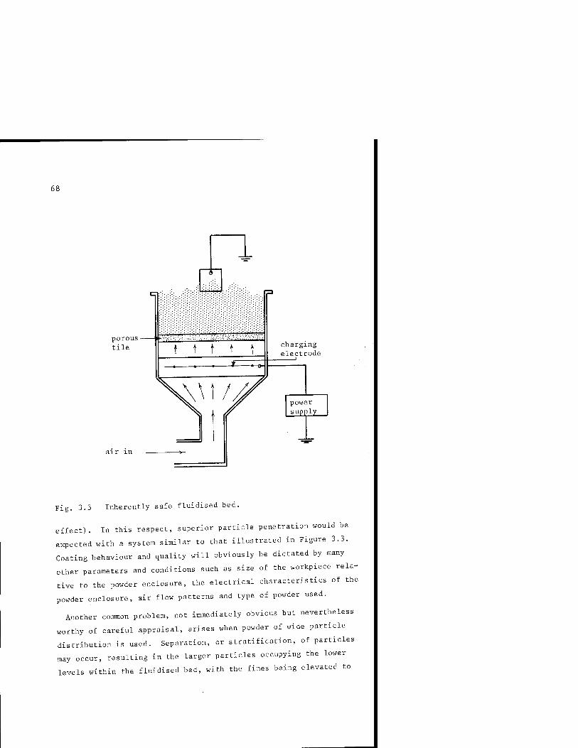
68
porous - tile t t t t t
charging electrode
power supply
Fig. 3.3 Inherently safe fluidised bed.
effect). In this respect, superior particle penetration would be
expected with a system similar to that illustrated in Figure 3.3.
Coating behaviour and quality will obviously be dictated by many
other parameters and conditions such as size of the workpiece rela-
tive to the powder enclosure, the electrical characteristics of the
powder enclosure, air flow patterns and type of powder used.
Another coimnon problem, not immediately obvious but nevertheless
worthy of careful appraisal, arises when powder of wide particle
distribution is used. Separation, or stratification, of particles
may occur, resulting in the larger particles occupying the lower
levels within the fluidised bed, with the fines being elevated to
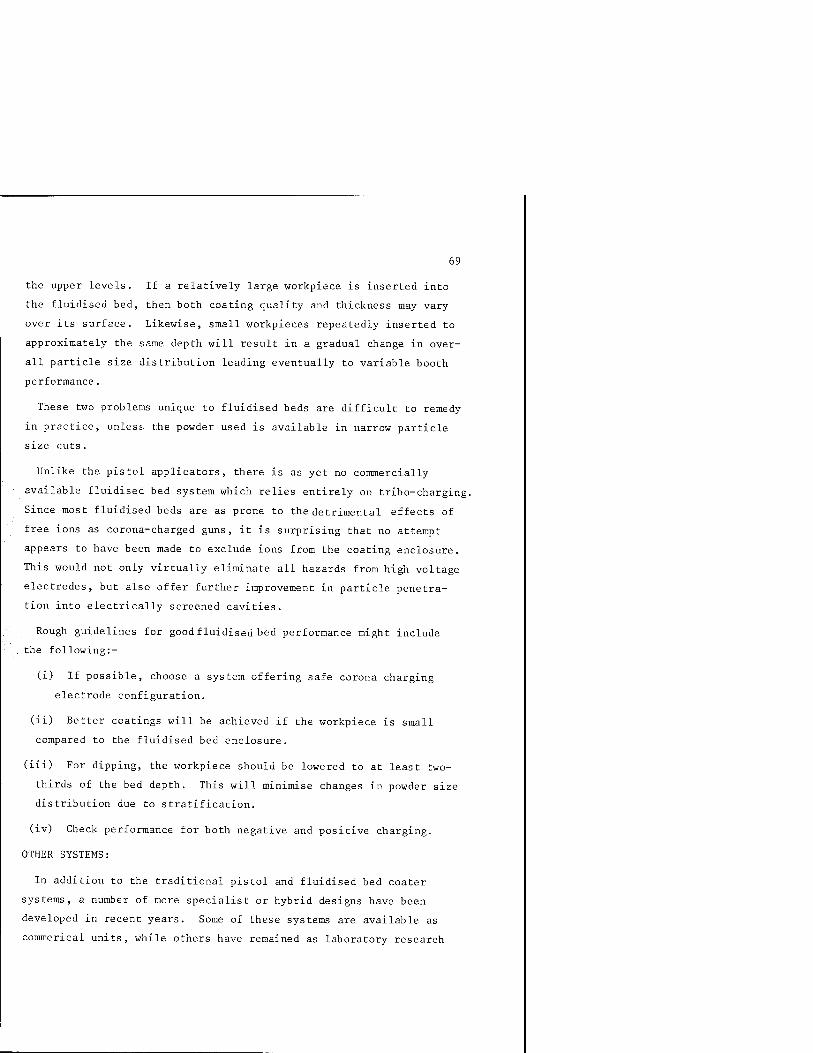
69
the upper levels. If a relatively large workpiece is inserted into
the fluidised bed, then both coating quality and thickness may vary
over its surface. Likewise, small workpieces repeatedly inserted to
approximately the same depth will result in a gradual change in over-
all particle size distribution leading eventually to variable booth
performance.
These two problems unique to fluidised beds are difficult to remedy
in practice, unless the powder used is available in narrow particle
size cuts.
Unlike the pistol applicators, there is as yet no commercially
available fluidised bed system which relies entirely on tribo-charging.
Since most fluidised beds are as prone to the detrimental effects of
free ions as corona-charged guns, it is surprising that no attempt
appears to have been made to exclude ions from the coating enclosure.
This would not only virtually eliminate all hazards from high voltage
electrodes, but also offer further improvement in particle penetra-
tion into electrically screened cavities.
Rough guidelines for goodfluidised bed performance might include
. the following:-
(i) If possible, choose a system offering safe corona charging
electrode configuration.
(ii) Better coatings will be achieved if the workpiece is small
compared to the fluidised bed enclosure.
(iii) For dipping, the workpiece should be lowered to at least two-
thirds of the bed depth. This will minimise changes in powder size
distribution due to stratification.
(iv) Check performance for both negative and positive charging.
OTHER SYSTEMS:
In addition to the traditional pistol and fluidised bed coater
systems, a number of more specialist or hybrid designs have been
developed in recent years. Some of these systems are available as
commerical units, while others have remained as laboratory research
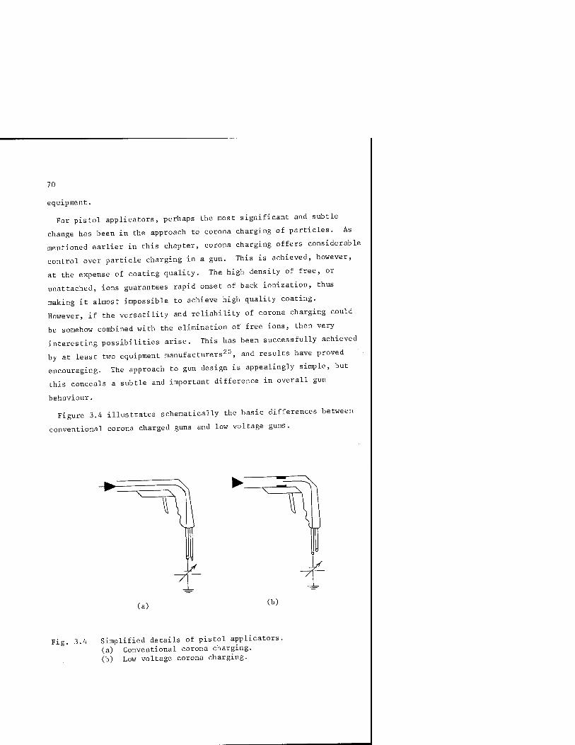
70
equipment.
For pistol applicators, perhaps the most significant and subtle
change has been in the approach to corona charging of particles. As
mentioned earlier in this chapter, corona charging offers considerable
control over particle charging in a gun. This is achieved, however,
at the expense of coating quality. The high density of free, or
unattached, ions guarantees rapid onset of back ionization, thus
making it almost impossible to achieve high quality coating.
However, if the versatility and reliability of corona charging could
be somehow combined with the elimination of free ions, then very
interesting possibilities arise. This has been successfully achieved
by at least two equipment manufacturers20, and results have proved
encouraging. The approach to gun design is appealingly simple, but
this conceals a subtle and important difference in overall gun
behaviour.
Figure 3.4 illustrates schematically the basic differences between
conventional corona charged guns and low voltage guns.
(a) (b)
Fig. 3.A Simplified details of pistol applicators. (a) Conventional corona charging. (b) Low voltage corona charging.

71
In the conventional gun, all the voltage is dropped between the
charging electrode at the gun head, and workpiece. Since this spac-
ing can be of the order of 1 metre, or more, relatively high voltages
are necessary in order to achieve high enough electric fields at the
electrode tip for corona onset. As described earlier, this creates
a relatively complex environment in which accurate particle manipula-
tion is attempted. Charged particles will be subjected to both
electrical and mechanical forces as a result of interaction with the
field and air flow, and this will be further complicated by the
effects of high free ion density.
On the other hand, the low voltage gun configuration offers a
simpler particle environment. The charging electrode is retracted
into the barrel of the gun, and an additional ground electrode is
incorporated into the charging region. This effectively replaces
the ground offered by the workpiece in the coating booth, and this
'internal' ground can be in close proximity to the high voltage
charging electrode. The same high corona onset electric field can
therefore now be achieved with a much lower electrode voltage.
Reductions from typical operating voltages of about 80 kV, down to
about 6 kV, are typical. Considerable gains in size, cost and com-
plexity of the high voltage supply are therefore clear advantages.
Since the corona discharge is restricted and confined to a small
volume within the gun barrel, through which all particles must pass,
considerable improvement might be expected both in charging effi-
ciency and the overall chargeability (q/m). Comparison tests on
high and low voltage guns have indicated the following mean charge-
to-mass ratios:-
-4 -1 Typical high voltage guns 5 x 10 C.kg
Typical low voltage guns 10 C.kg
In each case, measurements were made using the irrigated grid
technique described in Chapter 2, thus eliminating any errors due to
free ions. Charging efficiency tests also indicated a marginal
improvement using low voltage guns.

72
All unattached free ions are captured by the grounded counter
electrode within the gun barrel, thus eliminating all the free ion
population in the region between gun nozzle and workpiece. In many
respects, this type of gun creates a charged powder cloud situation
which is analogous to that produced by a tribo-charged gun - that is,
no free ions. Unlike the tribo gun, however, the low voltage type
gun benefits from the advantages of the controllability of corona
charging.
Since none of the externally applied voltage is dropped between
the gun head and workpiece, it might be reasonable to assume that
particle trajectories between the gun head and workpiece were governed
primarily by air flow patterns and that no electric field exists
between the gun head and workpiece. In reality, the situation is not
this simple. Although no free ions traverse the region between the
gun head and workpiece, the charged particles emanating from the gun
nozzle will themselves create an electric field. Diffusion of
particles under the influence of this field will contribute to
particle motion, but the overall effect will be small compared to
aerodynamic forces. A more intense electric field exists, however,
which is not always obvious when first assessing this type of gun.
This electric field arises directly from an electro-gas-dynamic
(EGD) mechanism which occurs within the gun barrel itself. Detail
of a typical low voltage gun barrel is illustrated in Figure 3.5.
As particles become charged by the corona source and subsequently
conveyed down the gun barrel towards the nozzle and diffuser, deposi-
tion and accumulation along the inside surface of the barrel and
nozzle/diffuser arrangement will occur. This accumulation of charged
particles leads directly to a voltage build-up on the nozzle and
barrel relative to the grounded counter electrode in the charging
region. Generation of voltage in this way is analogous to the moving
belt Van de Graaff generator, and a simple mathematical relationship
may be used to describe the mechanism.
As accumulation of charge occurs on the gun barrel and nozzle;
the potential builds up relative to the corona injector. The

73
0 V charge accumulation
insulating barrel #
'v6kV
Fig. 3.5 Detail of low voltage gun.
electric field developed between the nozzle and injector exerts a
repelling force on further charged particles moving towards the
nozzle. Due to the strong coupling that occurs between the charged
particles and the air flow, the net charged particle movement may be
represented by the expression:
charged particles
V . air
yE (i)
where v . is the velocity of the air, y the mobility of charged
particles, and E the local electric field.
The theoretical maximum potential developed on the nozzle may be
defined by the condition that charged particles can no longer reach
it. That is, the charge carriers remain stationary in the air flow
between injector and nozzle. Thus, in equation (i):
charged particles
and
yE (ii)

74
If space charge effects are completely neglected and other field V
non-uniformities are negligible, it is possible to write E as -j ,
where V is the generated voltage at the nozzle and 'd' is the
injector-nozzle spacing. Thus, rearranging equation (ii) gives:
charged V = particles (ii^^) generated
Note: This simple theory also assumes that no back ionization occurs
within the barrel of the gun as a result of charged particle
accumulation.
Equation (iii) is a useful relationship which may be used as a
simple guide for gun design. Two easily controllable parameters are
the velocity of the charged particles and 'd', the barrel length.
The voltage generated at the nozzle may therefore be enhanced by
increasing the gun forward air velocity - resulting in an increase
in V , or increasing the barrel length, or both. This charged particles
dependence on barrel length, d, is especially interesting in that it
highlights the importance of gun geometry in the achievement of
optimized performance. Coating evaluations for egd guns of this type
have indicated that superior coating behaviour will be achieved only
for a specific barrel length, which in turn implies that a voltage at
the nozzle is essential for acceptable performance. This might appear
to contradict the conditions conducive to good performance for exter-
nally charged corona guns; but the main and important difference
between the two systems is that one gun produces a copious supply of
free ions, while the egd system delivers a powder cloud completely
void of free ions. The implications are, therefore, that a high
density of free ions is detrimental to good coating, while the
existence of an electric field between gun and workpiece might, after
all, be a contributive factor to ;jood electrostatic performance,
especially in terms of wrap-around and general improvement in particle
trajectory patterns.

75
An interesting hybrid gun system has been developed in East Germany,
and to the author's knowledge no equivalent system is available in
the West. A schematic of the gun arrangement is illustrated in
Figure 3.6.
/I I
corona discharge
powder
Fig. 3.6 Schematic of corona-assisted tribo gun.^
Air and powder enter the gun through separate ports. The primary
particle charging mechanism is by frictional contact with the inside
surface of the gun barrel. A pointed earthed electrode is mounted
axially downstream of the powder feed port.
Assuming the powder charges positively by friction on the gun
barrel, as illustrated in Figure 3.6, for each positive charge
appearing on a particle there will be an equal and opposite negative
charge deposited on the internal surface of the barrel. With
repeated particle contacts, this negative charge accumulation will
be enhanced and will in turn create a high electric field at the
sharp pointed end of the earthea electrode. At a sufficiently high
local electric field, ionization of the air will occur in the vicinity
of the point resulting in the injection of positive (in this case)
ions into the air stream. This secondary source of positive charge

76
enhances the overall charging efficiency of the gun.
The approach is unique in that corona charging is induced in the
system without the requirement of a high voltage supply. The propor-
tion of the free ions captured by particles is not clear; this would
obviously be an important factor both in terms of particle charging
enhancement and overall system behaviour related especially to onset
of back ionization.
A typical characteristic of tribo-charged guns is the tendency for
particle charging efficiency to decline with continued use. This
could be attributed to a number of factors, but most likely to be
the result of particle accumulation on the inside surface of the gun
barrel - sometimes leading to a partially cured film, or simply an
exhaustion of charge exchange sites at the contact interface. This
latter suggestion is, however, speculation and little is known about
the fundamentals of charge exchange at an interface. Whatever the
cause, it is unlikely that this East German gun is immune from these
problems, and it is unclear from the published work available22 just
how performance will be affected over prolonged periods of operation.
Another interesting approach to dual charging in a gun is the
Cyclo-gun marketed by Senkyo-Denkyo of Japan. The approach is dif-
ferent from that adopted in the East German gun, but again both tribo
and corona charging have been combined into one gun. The system is
illustrated schematically in Figure 3.7. This system is unique in a
number of ways. First, the hollow barrel of the gun is itself a
small cyclone, thus enabling efficient contact of the powder with
internal surfaces. In addition to tribo-charging, two corona
charging stations are incorporated into the gun. Details of corona
charging at the gun nozzle are illustrated in Figure 3.7(b). The
gun is primarily a tribo gun with active supplementary corona
charging.
As powder and air enter the cyclone-shaped barrel of the gun,
aerodynamic forces result in flow patterns which ensure intimate
contact between powder particles and the barrel inner surface.
Powder is therefore restricted to a narrow band as shown in

77
(a) paint
5
V
exhaust outlet
secondary electrode
tribo charging section
(b)
Fig. 3.7 Cyclo-Gun. (a) Complete system. (b) Detail of gun nozzle.

78
Figure 3.7(b). Although tribo-charging efficiency must be enhanced
by adopting the cyclone geometry, attempts were made at increasing
further the overall charging efficiency by adding two corona charging
stages. The first corona charging stage is inside the gun nozzle,
thus depositing charge on the 'inside' surface of the powder film,
while the second corona charging stage is external and charges the
'external' surface of the powder film.
With this design the charging efficiency must be improved, although
it must be said that this will be achieved by forfeiting the benefits
of superior coating quality associated with ion-free guns. Both the
low voltage egd type of guns and tribo guns eliminate free ions,
while this system, in addition to being fairly complex, also creates
a high density of free ions. Also, in contrast to the East German
gun, the polarity of natural charging would require constant monitor-
ing in order to enable the correct choice of corona charging polarity
- an operating 'quirk' also shared by the egd gun systems.
In addition to reducing or eliminating free ions in a coating pro-
cess, it is also sometimes desirable to reduce or limit the air
throughput in a gun. As mentioned earlier in Chapter 1, too high an
air flow can lead to complete swamping of electrical effects on
particle trajectories, leading to deterioration in coating efficiency
due to overshooting of the workpiece. In instances where a very low
forward component of air velocity is required, techniques are
available which enable air-less projection of charged particles -
although care should ' 'aken when interpretating the term 'air-less'.
A simple air-less coater might adopt the configuration shown in
Figure 3.8. Here, the gun is reduced simply to an inclined plane at
the end of which is attached either a needle or sharp blade electrode.
Basically, the system resembles conventional externally-charged
corona guns. High potential applied to a sharp electrode creates a
highly ionized region of air in the vicinity of dispersed powder
particles. In the air-less gun, or blade-coater, as it is sometimes
known, the only difference is the way in which powder is conveyed to
the charging region. Conventional guns suspend powder particles in
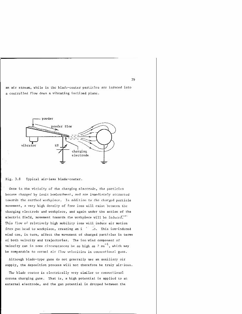
79
an air stream, while in the blade-coater particles are induced into
a controlled flow down a vibrating inclined plane.
vibrator
Fig. 3.8 Typical air-less blade-coater.
Once in the vicinity of the charging electrode, the particles
become charged by ionic bombardment, and are immediately attracted
towards the earthed workpiece. In addition to the charged particle
movement, a very high density of free ions will exist between the
charging electrode and workpiece, and again under the action of the
electric field, movement towards the workpiece will be induced"!
This flow of relatively high mobility ions will induce air motion
from gun head to workpiece, creating an i - ' .li. This ion-induced
wind can, in turn, affect the movement of charged particles in terms
of both velocity and trajectories. The ion wind component of
velocity can in some circumstances be as high as 2 ms , which may
be comparable to normal air flow velocities in conventional guns.
Although blade-type guns do not generally use an auxiliary air
supply, the deposition process will not therefore be truly air-less.
The blade coater is electrically very similar to conventional
corona charging guns. That is, a high potential is applied to an
external electrode, and the gun potential is dropped between the

80
blade head and workpiece. In situations where high electric field
effects are required, this technique may have advantages, but pene-
tration into corners and cavities will be poor.
Blade coaters are used where special coating requirements are
sought, and are therefore usually installed as 'one-off custom
packages.
An interesting variation of the blade coater is the rotating disc.
Here the blade is replaced by a sharp edged rotating disc. A typical
commercial system is illustrated in Figure 3.9. With the disc rotat-
ing in a horizontal plane, powder fed onto its upper surface will be
projected radially outwards under the action of centrifugal forces.
With the disc maintained at a high potential, particle charging will
be effected at the sharp edge by ionic attachment. The radial motion
of particles will therefore be enhanced by both electrical field
effects and ion induced wind.
Fisj. 3.9 Typical powder disc system. (photo courtesy G & R Electro-Powder Corp.)

Like the blade coater, this system creates a very high density of
free ions, and the entire potential is dropped between the high-
voltage disc and workpiece. Rapid onset of back-ionization would
therefore be expected, together with poor penetration characteristics.
However, penetration may be better than with the static blade system,
since particle velocities will be substantially enhanced by centrifu-
gal forces.
Disc coaters appear to lend themselves very well to situations
requiring high powder handling rates. The rapid coating of large
panels, for example, is possible with just one disc unit. Typical
conveyor arrangement might be as shown in Figure 3.10. With a verti-
cally reciprocating disc, and carousel conveyor loop, coating of all
surfaces will be possible with the single disc.
Fig. 3.10 Conveyor loop with disc coater.

82
COATING BOOTHS
Of all the hardware associated with powder coating, the booth has,
until recently, been very much neglected in terms of its importance
in affecting coating behaviour and quality. Many commercial booths
are still little more than metal boxes - with the only hint of fore-
thought being in the size of the gun ports and other openings rela-
tive to the amount of extraction air to be used. As long as no
powder excaped the confines of the booth, the system would be accep-
table at least with respect to maintaining a clean and particle-
free atmosphere at and around the coating line.
It is only relatively recently that more serious consideration has
been given to booth design, with special emphasis and appreciation
of how the booth itself can be instrumental in determining the over-
all performance of coating plant.
For example, in a metal booth of fixed dimensions, will there be an
optimum size of workpiece for high deposition effiency? This would
seem to be a reasonable supposition. Consider small workpieces in a
large booth. The largest and certainly the most dominant earthed
object will be the booth itself. Many of the electric field lines
originating at the gun head will terminate on the booth walls, with
the booth therefore presenting itself as a major competitor for
powder deposition. This situation will be highly undesirable in many
ways. Coating efficiency on the workpiece will be unacceptably low,
and the deposition on the booth walls will extend considerably the
time required for powder colour change. Conversely, with a large
workpiece relative to overall booth size wrap-around properties will
be affected, resulting again in poor coating efficiency and possibly
necessitating the doubling of the number of guns necessary to ensure
even coating on all sides.
It is possible to estimate the optimum booth size for a particular
coating line, and this will be considered in Chapter 4.
Although metal booths are still very much the 'norm' in coating
installation, a number of interesting alternatives have recently

83
appeared on the commercial market. Perhaps the most radical change
in booth design has been the introduction of the plastic booth, in
hindsight a reasonably obvious choice of material. With the booth
itself fabricated of insulating material it no longer competes with
the workpiece for particle collection. In fact, the inside walls
will themselves become highly charged by ionic collection, and will
thus tend to repel approaching charged particles. This will be bene-
ficial both in terms of maintaining clean walls and rapid colour
change, and contributing towards an improvement in collection effi-
ciency on the earthed workpiece.
These benefits are only likely to occur when a high density of free
ions is generated by the guns; thus, when using the combination of
plastic booths and ion-free guns, care should be exercised if im-
proved performance is required. The ion-free guns might offer
improvement in coating quality and penetration characteristics, but
without charge build-up on the booth walls the plastic booth is
unlikely to show a marked improvement in deposition efficiency.
Figure 3.11 illustrates schematically the difference in electric
field line pattern between metal and plastic booths when used in
conjunction with a conventional high-voltage corona charged gun.
An interesting derivative of the plastic booth approach has been
the tunnel coating systems. A number of different designs have been
available commercially, each with its own special feature. The
Volstatic Super Coater was especially interesting in that a number
of unique ideas were incorporated into one system. The booth itself
was fabricated entirely of Perspex, thus ensuring very high wall
resistivities. In addition, the length of the booth was extended
thus enabling an increase in residence time of workpieces on a con-
veyor. There was a specific reason for the latter innovation.
Usually, standard high-voltage corona charged guns would be installed
in the tunnel booth, but operated at drastically reduced powder feed
rates. This in itself offered improved particle charging efficiency
at the gun heads, since for the same charge density fewer particles
passed through the space charge. With this lower powder feed rate.
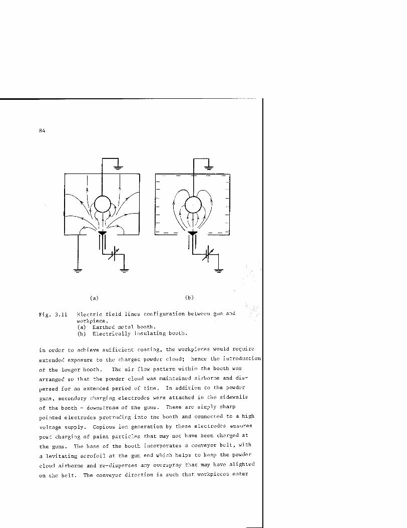
84
(a) (b)
Fig. 3.11 Electric field lines configuration between gun and workpiece. (a) Earthed metal booth. (b) Electrically insulating booth.
in order to achieve sufficient coating, the workpieces would require
extended exposure to the charged powder cloud; hence the introduction
of the longer booth. The air flow pattern within the booth was
arranged so that the powder cloud was maintained airborne and dis-
persed for an extended period of time. In addition to the powder
guns, secondary charging electrodes were attached in the sidewalls
of the booth - downstream of the guns. These are simply sharp
pointed electrodes protruding into the booth and connected to a high
voltage supply. Copious ion generation by these electrodes ensures
post charging of paint particles that may not have been charged at
the guns. The base of the booth incorporates a conveyor belt, with
a levitating aerofoil at the gun end which helps to keep the powder
cloud airborne and re-disperses any overspray that may have alighted
on the belt. The conveyor direction is such that workpieces enter

85
the booth at the end opposite the guns. This ensures that particles
that have been airborne for the longest time have first priority in
terms of deposition on the workpiece. An important consideration in
a system which inevitably will be prone to rapid onset of back-
ionization. The high free ion density ensures adequate charge build-
up on the walls of the booth, but this is achieved at the expense of
a very high density of charge arrival on the workpiece - hence
severe back-ionization.
Figure 3.12 illustrates schematically a typical tunnel coating
system. Also shown is the air extraction and cyclone arrangement.
air extraction unit
dielectric booth
Levitating aerofoil
conveyor direction
conveyor
Fig. 3.12 Simplified schematic of Volstatic Super Coater system.
Numerous variations of this coating arrangement have been available
commercially, notably one system which has large electrically
isolated metallic plates incorporated into the insulating walls of
the booth. These plates would rapidly accumulate both charged
particles and free ions. Particle collection may be advantageous as
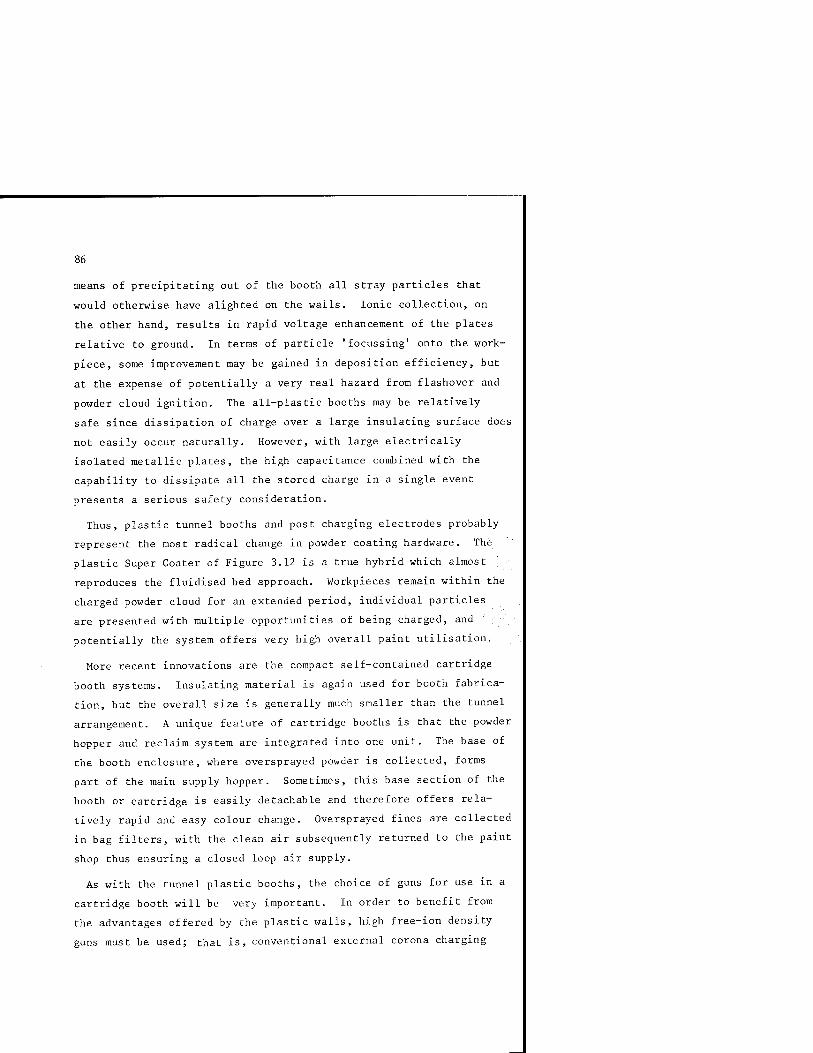
86
means of precipitating out of the booth all stray particles that
would otherwise have alighted on the walls. Ionic collection, on
the other hand, results in rapid voltage enhancement of the plates
relative to ground. In terms of particle 'focussing' onto the work-
piece, some improvement may be gained in deposition efficiency, but
at the expense of potentially a very real hazard from flashover and
powder cloud ignition. The all-plastic booths may be relatively
safe since dissipation of charge over a large insulating surface does
not easily occur naturally. However, with large electrically
isolated metallic plates, the high capacitance combined with the
capability to dissipate all the stored charge in a single event
presents a serious safety consideration.
Thus, plastic tunnel booths and post charging electrodes probably
represent the most radical change in powder coating hardware. The
plastic Super Coater of Figure 3.12 is a true hybrid which almost
reproduces the fluidised bed approach. Workpieces remain within the
charged powder cloud for an extended period, individual particles
are presented with multiple opportunities of being charged, and
potentially the system offers very high overall paint utilisation.
More recent innovations are the compact self-contained cartridge
booth systems. Insulating material is again used for booth fabrica-
tion, but the overall size is generally much smaller than the tunnel
arrangement. A unique feature of cartridge booths is that the powder
hopper and reclaim system are integrated into one unit. The base of
the booth enclosure, where oversprayed powder is collected, forms
part of the main supply hopper. Sometimes, this base section of the
booth or cartridge is easily detachable and therefore offers rela-
tively rapid and easy colour change. Oversprayed fines are collected
in bag filters, with the clean air subsequently returned to the paint
shop thus ensuring a closed loop air supply.
As with the tunnel plastic booths, the choice of guns for use in a
cartridge booth will be very important. In order to benefit from
the advantages offered by the plastic walls, high free-ion density
guns must be used; that is, conventional external corona charging
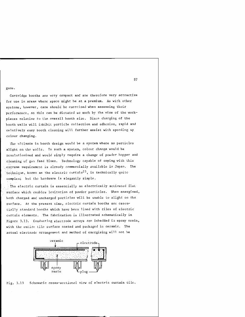
87
guns.
Cartridge booths are very compact and are therefore very attractive
for use in areas where space might be at a premium. As with other
systems, however, care should be exercised when assessing their
performance, as this can be dictated so much by the size of the work-
pieces relative to the overall booth size. Since charging of the
booth walls will inhibit particle collection and adhesion, rapid and
relatively easy booth cleaning will further assist with speeding up
colour changing.
The ultimate in booth design would be a system where no particles
alight on the walls. In such a system, colour change would be
revolutionised and would simply require a change of powder hopper and
cleaning of gun feed lines. Technology capable of coping with this
extreme requirement is already commercially available in Japan. The
technique, known as the electric curtain^^, is technically quite
complex; but the hardware is elegantly simple.
The electric curtain is essentially an electrically activated flat
surface which enables levitation of powder particles. When energised,
both charged and uncharged particles will be unable to alight on the
surface. At the present time, electric curtain booths are essen-
tially standard booths which have been lined with tiles of electric
curtain elements. The fabrication is illustrated schematically in
Figure 3.13. Conducting electrode arrays are imbedded in epoxy resin,
with the entire tile surface coated and packaged in ceramic. The
actual electrode arrangement and method of energising will not be
1
epoxy resin
P electrode-.
m WW t-plug
Fig. 3.13 Schematic cross-sectional view of electric curtain tile.

dealt with here, but an important feature is the difference in
behaviour between single-phase and three-phase a.c. operation. When
supplied with single-phase a.c. voltage, charged and uncharged
particles will simply experience a force in a direction away from the
tile surface. Levitation will occur, thus ensuring the tile surface
will be free of all particles. However, if three-phase a.c. voltage
is used, an additional force will be exerted in a direction parallel
to the surface of the tile. Thus, in addition to levitation,
conveyance of the particles will also be possible.
These two modes of operation are put to use very effectively in a
powder coating booth. ^'* The side walls and back surface of the
booth are installed with single phase electric curtain tiles, while
a trough at the base of the booth, when energised with three-phase
a.c. voltage, will collect and transport the overspray out of the
booth and into the re-claim hardware. All this will be accomplished
with no powder alighting on any part of the booth wall. The implica-
tions of this on colour change are immediately obvious. Figure 3.14,
illustrates schematically a typical booth arrangement with electric
curtain tiles installed.
Electric curtain panels have been installed in numerous commercial
coating plants, where the application is not always to prevent
deposition on booth walls.
An interesting example is in powder coating of glass bottles. Here
panels installed on the inside walls of the coating booth are
arranged in such a way as to optimize the position of the airborne
powder cloud after injection by standard corona-charged guns.
Figure 3.15 illustrates schematically how this arrangement effec-
tively 'focusses' the airborne cloud in close proximity to the
workpiece.
Many new innovations are constantly appearing and being incorpora-
ted into commercial hardware. In Japan developments have been parti-
cularly significant and will undoubtedly lead to important changes in
the entire concept of powder coating. Indeed, there will undoubtedly
be many more innovations in the powder coating application equipment
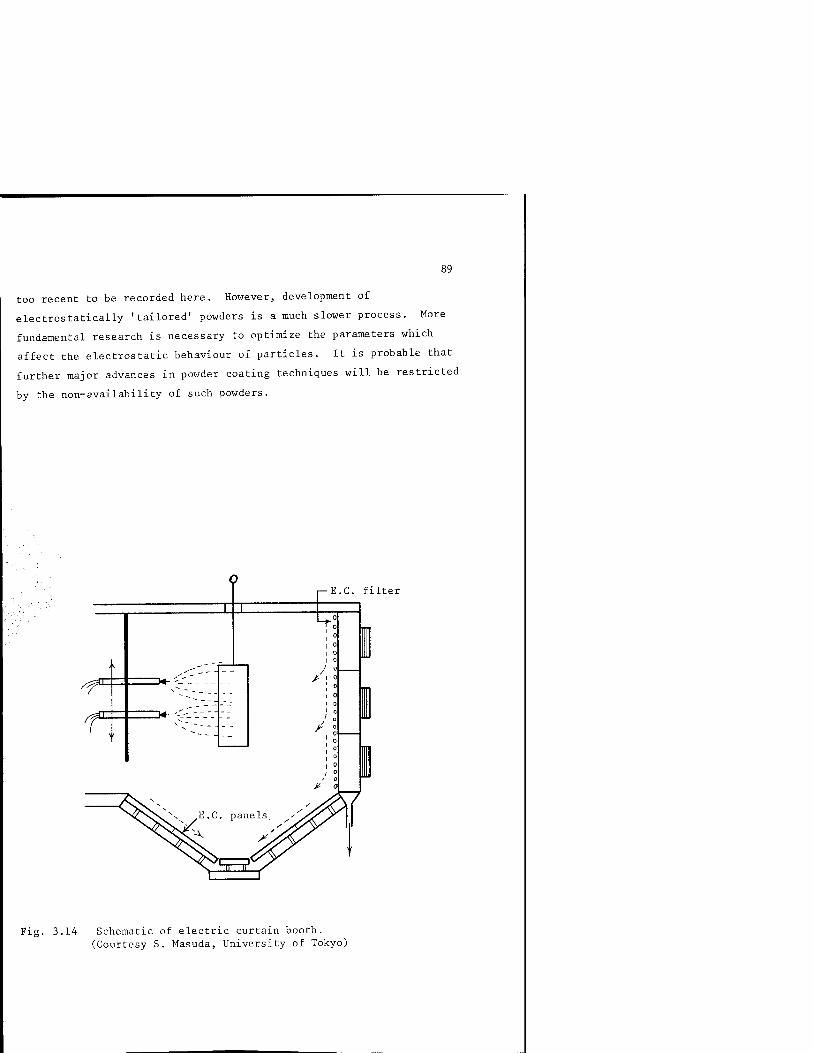
89
too recent to be recorded here. However, development of
electrostatically 'tailored' powders is a much slower process. More
fundamental research is necessary to optimize the parameters which
affect the electrostatic behaviour of particles. It is probable that
further major advances in powder coating techniques will be restricted
by the non-availability of such powders.
T
■E.G. filter
A
> 0
Fig. 3.14 Schematic of electric curtain booth. (Courtesy S. Masuda, University of Tokyo)
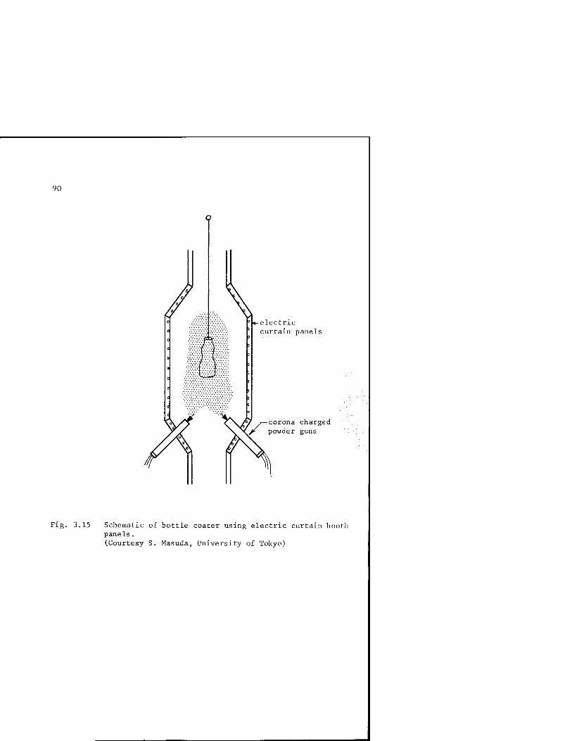
90
■electric curtain panels
corona charged powder guns
Fig. 3.15 Schematic of bottle coater using electric curtain booth panels . (Courtesy S. Masuda, University of Tokyo)

91
CHAPTER 4 System Optimization
System optimization is possibly the most difficult task in the entire
process of powder coating. The fact that the performance of any
system is dependent on so many variables almost always necessitates
a compromise in the choice of parameters. Below is a list of a few
variables that require consideration when setting out to design a
complete coating system:
(i) Size and shape of workpiece(s).
(ii) Size and shape of booth,
(iii) Booth material.
(iv) Conveyor speed.
(v) Type and number of guns,
(vi) Powder to be used,
(vii) Colour change requirements,
(viii) Powder feed rates,
(ix) Quality of coating.
For most applications, there will be constraints on the choice of
an idealised system. For example, there will be a finite choice of
booth and gun arrangements, and usually the choice of powder will
be restricted by the type and quality of finish.
What are the initial considerations when setting up a system,
excluding possible financial constraints? Obviously, the booth/gun
arrangement will have to be physically big enough and fast enough to
handle the proposed throughput of workpieces. Coating efficiency
should be as high as possible, requiring the minimum re-claiming and
92
re-blending. The quality of the finished product should meet the
required standards.
Most commercial equipment, when set-up for demonstration purposes,
will meet these requirements convincingly. However, many will behave
very differently after prolonged use in the paint shop. The reasons
are not always easily identifiable, and often other more definitive
factors must be carefully evaluated.
During equipment demonstrations, the following points should be
considered:
(i) Is coating behaviour consistent for different shapes and
sizes of workpieces?
(ii) Assess the coating behaviour for different gun voltages, if
corona-charged guns are used.
(iii) Assess the coating behaviour for different powders if tribo- ■
charged guns are used. . ,
(iv) Coating behaviour should be assessed after a period of about
four hours of continuous operation.
(v) Assess the coating behaviour for different gun currents if
constant current facilities are available.
Most of these points can be assessed by direct observation of coating
behaviour, when much useful informati- btained. However,
assessment should not end here. if possible, ^asurement of key
parameters should be made at different ' during the coating
demonstration. Important measurements, ^ich are not difficult to
make, should include:
(i) Identification of the sign of the natural tribo-charging
component of the powder. This is important, especially in corona-
charged guns, where the sign of the corona-charging should be
matched to the sign of the tribo-charging.
The measurement is quite strc -forward, and requires only
a standard electrometer charge measuring instrument or a field
mill.

93
In a corona-charged gun system, the following sequence could
be adopted as a simple guide:
(a) Switch-off external power supply to gun head.
(b) Attach sample workpiece to electrometer input, or alternatively,
use a field meter as a remote sensor.
(c) Switch on the powder and air feed and coat the workpiece.
(d) Determine sign of naturally-charged powder.
This important but simple measurement could have important implica-
tions in system behaviour.
If the natural charging of the powder is negative, then the corona
charging should be negative, and likewise for positive charging.
. Some materials can have significant tribo-charging characteristics,
which in extreme cases could nullify the corona charging. Obviously,
a,choice of appropriate polarity would be desirable.
•;; Although most commercial corona-charged guns are produced with
negative charging, some manufacturers are offering a choice of
polarity. At the present time, the choice appears to be 'either-or'.
A gun offering reversible polarity might be an interesting proposition,
especially for the user who may wish to use his equipment with a
variety of powders. However, currently the operational advantages of
this type of gun are .^^ntlv outweighed by the cost penalties
incurred in installinv :-iversibi_ ..piolarity high-voltage supplies.
(ii) Check powder refe. ' v at intervals during the demonstration.
Portable equipment which■.■:„:...^Dles rapid and easy measurement of
resistivity is now commercially available (see Chapter 2). Multiple
checks are advised especially in a demonstration unit which includes
re-claim and re-blending. The characteristics of the powder will
change as re-claimed powder is added to virgin powder, and it has
been found that resistivity is especially sensitive to the percen-
tage doping of re-claim to v-' ^in. Since resistivity appears to be
closely associated with chargeability, changes occurring in the
powder over a prolonged period of operation will be very important.
94
Different systems will have different effects on powder
deterioration associated with re-claim. The nature of changes in
the powder is not clearly understood. Certainly the powder size
distribution changes, probably due to a combination of mechanical
damage to individual particles and preferential deposition of
specific sizes. However, it is more surprising that the charge-
ability of re-claimed powder will, in many cases, be very different
to the chargeability of virgin powder.
This simple measurement of resistivity can therefore give a
valuable indication not only of change of resistivity, but also of
general coating efficiency and more importantly, how much electro-
mechanical modification is imposed on the powder by the system under
test.
(iii) A measure of the charge-to-mass ratio of the powder is always
a useful test. Again, portable equipment is available (see Chapter
2), which enables this parameter to be measured relatively easily r:
at least when tribo-guns are being assessed. /
The measurement simply requires the capture of powder sample in a
Faraday enclosure which is in turn connected to a charge measuring
instrument. This should be done while the gun is set to normal
operating conditions. An accurate balance will be required to weigh
the captured powder sample - from which the ratio of charge-to-mass
may then subsequently be calculated. When assessing corona-charged
guns, considerably more care is required in ensuring that no free
ions enter the Faraday sample holder - in which case an erroneously
high value of charge will be measured.
Accurate measurements will only be possible by using the irrigated
grid method; but a good rough indication may be gained using commer-
cial dry grid ion traps. Powder sample collection times should then
be restricted to just a few seconds between grid decontamination.
Rigorous testing under laboratory conditions has indicated a
marked deterioration in charge-to-mass ratio with coating time, when
re-claimed powder is added to virgin powder.^5 There would appear

95
to be a correlation between the resistivity modification and the
change in charge-to-mass ratio, with the degree of modification being
dictated by the choice of powder/coating system combination.
-3 -1 A charge-to-mass ratLO of the order of 10 C.kg will normally
ensure good deposition characteristics. If this value can be main- ... 12
tained, together with a resistivity m excess of about 10 fJm, then
good electrostatic deposition should be expected.
The all-important test is to ascertain whether the original
resistivity and values for charge-to-mass ratio can be maintained in
a system after a few hours of continuous operation. If they are
consistent for the particular powder/coating system under evaluation,
it may be confidently assumed that good quality coatings will be
.possible. However, it does not imply that efficient coating deposi-
tion will always necessarily be guaranteed.
■ Once a system has been found which meets the general coating
requirements in terms of workpiece throughput, physical size of
equipment, number of guns required, etc., the real problem of
system optimization begins.
The plant designer should be in possession of at least one of
each type of diagnostic equipment mentioned in Chapter 2.
Essential tools of the trade should include:
(i) Powder resistivity test cell.
(ii) Charge-to-mass ratio equipment.
(iii) A field mill or field probe.
(iv) Current measuring instrument.
(v) High-voltage measuring instrument (up to 100 kV).
(vi) Earth testing equipment.
(vii) Air speed indicator.
Assuming a standard metal booth/corona-charged gun system was to be
evaluated, setting up procedures might include the following tasks:

96
BOOTH AND GUN AIR
In any open-fronted booth, a negative air pressure must be main-
tained at all times if powder leakage into the surrounding environ-
ment is to be avoided. This is a basic requirement which must be
ensured prior to any other setting-up procedure. In addition to
simply ensuring the maintenance of negative pressure, the actual air
velocity in the vicinity of the gun port and workpiece will be an
important factor in determining particle trajectories. Ion wind and
gun forward air velocities have been found to be comparable, and
typically can be of the order of a few metres per second. These
latter two components of velocities can, to some extent, be con-
trolled and used to advantage when certain coating behaviour is
required. Ideally, therefore, booth air velocities at the gun head
and workpiece should be arranged to be well below a few metres per
second. If not, particle trajectories may well be dominated by the
effects of the fixed and uncontrollable booth venting system.
Control of gun air will normally be easier, at least in convention-
al corona-charged guns, where both forward air velocity and in some
cases the air flow pattern may be adjusted. This may not be the
case in tribo-charged and air-less coaters. Air flow characteristics
may be less flexible in tribo-guns, since the prime consideration
will be powder flow patterns within the guns optimized for maximum
powder charging. In air-less guns, on the other hand, the forward
air velocity component will be that solely due to ion-induced wind.
Any attempt at changing this will necessitate a change in the corona
discharge, leading ultimately to inconsistent powder charging
characteristics.
In almost all powder coating arrangements, the ideal air flow
pattern will invariably be where the forward air velocity is just
sufficient to convey the airborne particles to close proximity of
the workpiece surface. As soon as particles are within about 2 cm
of the substrate, air flow effects should be at a minimum, and
electrostatic attraction forces begin to predominate, thus completing
the ideal trajectory with particles alighting and adhering to the
97
workpiece surface. In order to ensure adequate wrap-around, turbulent
air flow should be induced in the vicinity of the workpiece, but with
forward air velocities minimised wherever possible.
This general rule of thumb will hold for most workpieces, but
exceptions will arise with some special shapes. For example, when
coating of the inside of deep cavities or corners is required, an
abnormally high forward air velocity will be beneficial. The Faraday
cage effect will normally prevent access of charged particles into
such areas purely by electrical propulsion forces. Mechanical pro-
pulsion by means of a high forward air velocity must therefore be
used in order to overcome this sereening effect, which incidentally
will be more pronounced in corona-charged high-voltage guns with
external charging. Optimization of coating performance will only be
. achieved as a compromise between acceptable deposition efficiency and
coating quality. Inevitably, it will be difficult to achieve high
.deposition efficiency when internal coating of cavities is required.
A lower forward air velocity may be acceptable when using tribo-
charged or low-voltage internal-charging guns. These types of guns
may therefore offer considerable advantages over external-charging
high-voltage guns, and should be given serious consideration in
applications necessitating coating penetration.
GUN VOLTAGE AND CURRENT
Commercial equipment often includes a voltage indicator on the
front of the gun control panel. Invariably, this will be a measure
of the output voltage of the high voltage generator.
It is easy to misinterpret this indicator as being the voltage of
the gun charging electrode. During setting-up procedures, and indeed
for spot checking, a simple high-voltage measuring probe is always
very useful (see Chapter 2). An indication of the true charging
electrode voltage may be gained simply by contacting the probe with
the gun electrode. Some probes will even work without physical
contact, as long as their sharp metallic tips are in close proximity
to the high voltage electrode. The tip itself will corona discharge.

98
as a result of geometrical field intensification, resulting in the
end of the probe being raised in potential to approximately the same
value as the gun potential. A useful feature when access may be
restricted. This measurement is especially important if the condi-
tion of the high-voltage cable between generator and gun is in doubt.
A broken cable could mean zero potential at the gun head, with the
voltage indicator on the control panel indicating normal voltage
output.
The current indicator on the gun control panel will generally be a
measure of the current supplied by the high-voltage generator.
Usually this current will be measured in the earth return line of the
generator, and will be equivalent to the corona current at the gun
head. Clearly, the gun voltage and current will be interrelated,
except when guns are equipped and operated on a constant current mode.
In order to optimize powder charging in a corona-charged gun, ..;.V
powder flow rate will also play an important role in charging '''■'■}',■
efficiency. For a constant current, an increase in powder flow rate
will invariably lead to a reduction in charging efficiency. The
temptation then would be to increase gun current accordingly. This
may increase marginally the charging efficiency, usually at the
expense of accelerating the onset of back-ionization due to the
increased density of free ions.
Therefore, the choice of gun voltage and current will almost
always necessitate a compromise between an acceptable level of charg-
ing efficiency and the coating quality in terms of layer disruption
from back-ionization.
The best approach in this situation might be first to set up the
equipment such that coating behaviour appears visually acceptable.
At the chosen gun voltage and current, a check on particle charge-to-
mass ratio will then confirm whether, electrostatically, the system
is close to optimum performance. If the charge-to-mass ratio falls
to the order of lO"'' Ckg"^, then charging efficiency will be poor,
leading in turn to poor deposition efficiency.

99
Using the screened Faraday cup for charge-to-mass ratio, measure-
ment will give mean values of charge-to-mass ratio, which in most
applications will be quite adequate and useful in terms of determin-
ing system operation. This measurement will not, however, indicate
the proportion of the powder emanating from the gun that will carry
sufficient charge to be considered as potentially collectable on the
workpiece. There is a subtle difference between this measurement
and straightforward mean charge-to-mass ratio measurement. If an
indication of the proportion of charged to uncharged powder is
required, then the irrigated screen/L-shaped electrode technique
described in Chapter 2 will have to be used.
In terms of-coating performance and efficiency of deposition, this
will be the all—important parameter.
Charging efficiency may be defined in a number of ways, and care
-should be taken when interpreting this parameter. For example,
/cliarging efficiency could be thought of as a measure of the degree
-of particle charging relative to the Pauthenier limit. Although,
academically, this would be an interesting measurement, its practical
relevance would be of secondary importance compared to the L-shaped
electrode measurement.
EARTHING
Earthing of workpieces onto metal conveyor lines would appear to be
a relatively straightforward procedure. Jigging can, however, pose
a serious problem when earth continuity is to be maintained over a
prolonged period of operation. Most jigs are metal hangers or hooks
of varying shapes and sizes. There will normally be no problem with
a clean jig and uncoated workpiece. However, this situation rarely
exists in practice. The jigs themselves became coated and subsequent-
ly cured during passage through the oven. Earth continuity with a
plastic coated jig may not be maintained so easily when used for
multiple passes.
Since many jigs are simply sections of small diameter metal rods
bent into an appropriate shape, preferential coating of the jig will

100
not only lead to rapid deterioration of workpiece earthing, but also
to serious disruption of the overall coating performance. Previously
coated jigs will support rapid onset of back-ionization, leading to
a collapse in charging efficiency.
Both size and shape of jig will also be important in terms of
trajectory perturbation, and potential electro-mechanical screening
of localised regions on the workpiece surface.
Continuous checking of jig earthing is not difficult, and equip-
ment is available commercially for automatic monitoring.!^ ^h^t are
more difficult to monitor and control, however, are the continuously
varying effects of a slow but steady growth in jig coating thickness.
The choice and optimization of a particular booth/gun combination
involves considerable effort which will be wasted if no consideration
is given to jig design. For example, if the jig is large compared to
the workpiece, then parasitic coating will almost certainly occur. ; .,,
Sharp bends, corners, edges and points should be avoided whenever ; ..
possible. These geometries will not only exaggerate electric field ;^
modifications, but will also encourage preferential coating at the
expense of the workpiece. With respect to earth continuity, there
are two useful 'rules-of-thumb' which can promote improved perfor-
mance. The first, and most obvious, is to arrange, whenever possible,
for contact between jig and workpiece to occur where either no powder
deposition is required, or where coating thickness and quality is not
important. For example, on the inside of a casting where external
coating is primarily for aesthetic purposes. The second is to
arrange for the point of contact between the jig and workpiece to be
a sharp point. This not only minimises the inevitable, undesirable
jig marks, but also ensures electric field intensification at the
point of contact if the sharp point is coated. Under these condi-
tions, particle and ionic accumulation on the workpiece will result
in the voltage of the workpiece being raised above ground zero.
With a sharp point contact, intensification of the field between
workpiece and jig will ensure a breakdown across the contact point
at a relatively low workpiece voltage. The creation of such a

101
breakdown, and possibly a tracking path, will normally be sufficient
to ensure earth continuity even for relatively thick layers of jig
coating.
Table 3 lists some of the important considerations relating to
jigging optimization.
Good Jigging Practice
Jig should be a good conductor.
Overall dimensions small compared to workplace.
No sharp bends, points or corners.
Jig contact to workpiece by sharp point.
.Workpieces of similar shape and size jigged together.
Regular cleaning of coated jigs.
Poor Jigging Practice
Poor conductor. Heavily coated jig.
Large jigs supporting small well"Spaced workpieces.
Sharply angled sections used for jigs.
No consideration given to jig/workpiece connection.
Mixture of workpieces on s ame jig.
No established jig-cleaning programme.
TABLE 3. Hints on how to improve workpiece jigging.
Inevitably, coating requirements will differ from plant to plant,
and for that reason it is almost impossible to draw a universal
optimisation programme. However, with careful planning and an
appreciation of the implications of basic electrical parameters,
it is often possible to achieve considerable improvement in plant
performance. A rough guide to system optimization is illustrated
by the following flow chart.
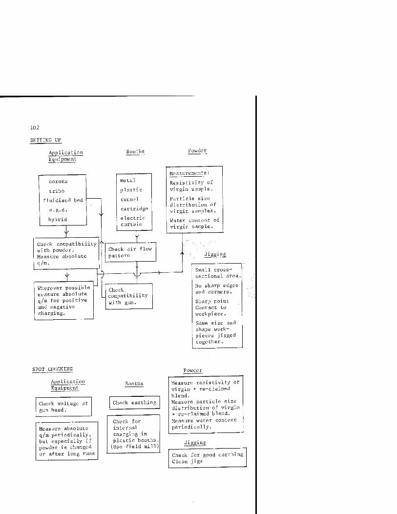
102
SETTING UP
Application Equipment
Booths
corona
tribo
fluidised bed
e.g.d.
hybrid
Check compatibility with powder. Measure absolute
q/m.
Vfherever possible measure absolute q/m for positive and negative charging.
metal
plastic
tunnel
cartridge
electric curtain
Check air flow pattern
-Vy
Check compatibility
with gun.
Powder
Measurements:
Resistivity of virgin sample.
Particle size distribution of virgin samples.
Water content of virgin sample.
Jigging
Small cross- sectional area.
No sharp edges and corners.
Sharp point Contact to workpiece.
Same size and shape work- pieces jigged together.
SPOT CHECKING
Application Equipment
Check voltage at gun head.
Measure absolute q/m periodically, but especially if powder is changed or after long runs
Booths
Check earthing
Check for internal charging in plastic booths. (Use field mill)
Powder
Measure resistivity of virgin + re-claimed blend. Measure particle size distribution of virgin + re-claimed blend. Measure water content periodically.
Jigging
Check for good earthing Clean jigs

103
It is always useful, both during demonstrations, setting-up and
on-line spot checking, to be familiar with at least the orders of
magnitudes of the relevant electrical parameters. Listed below are
some of the more important 'rule-of-thumb' numbers.
Resistivity
For acceptable adhesion. 12
> 10 flm.
Excellent adhesion but probably difficult to charge efficiently and rapid onset of back-ipnizatipn with corona-charged "gun's.
> 10'^ am.
Charge-to-mass ratio
(q/m)
-3 -1 10 C.kg
Poor electrostatic behaviour
-4 -1 < 10 C.kg
Excellent charging but poor adhesion.
< 10 fim.
Compromise resistivity for generally good charging and acceptable adhesion.
12 10 nm.

105
CHAPTER 5 Future Trends
EQUIPMENT - ■
The ultimate goal for almost all powder coating applications is the
jability to deposit a thin, even thickness, high quality coating as
efficiently as possible. Some systems already come close to achiev-
■ ing this, but usually only at the expense of system flexibility.
; That is, if the same gun, booth, powder and workpiece combination is
to be used over a prolonged period, then the system may be optimized
to give good performance. In order to maintain optimization, however,
spot checks will be required at pre-determined intervals. Gun charg-
ing might change with variation in powder blend of re-claim to virgin,
for example; and this would require periodic checking.
What is more difficult to achieve, however, is the maintenance of
optimized performance when conditions on the coating line change; for
example, regular powder colour or type change and different work-
pieces. Under such varied condit s, there will be little chance of
achieving optimal performance, and normally the procedures for set-
ting up the system will involve trial and error. Important electri-
cal parameters will rarely be measured, and under such circumstances
the advantages associated with electrostatic deposition will often
be lost.
It appears likely t . there will be increasing use of plastics for
booth fabrication. At the present time, however, booths still appear
to be nothing more than plastic boxes. Electrical optimization of
plastic booths will undoubtedly lead to an improvement in performance,
106
and computer modelling techniques already make accurate predictions
of system behaviour possible under varying conditions.
Low voltage egd guns have certainly contributed to improvement in
powder charging, and have led the way in a totally new approach to
coating techniques. Since some guns can contribute a substantial
tribo component of charging, it is possible that a future system
could usefully incorporate a polarity sensor coupled with a reversi-
ble polarity power supply. Any change in polarity due to a change in
powder would then automatically be catered for, with the 'correct'
choice of corona charging polarity always ensured. In fact, for low
voltage guns, this is by no means an impossible feature, "but is a
refinement which perhaps would be difficult to justify" in'terms of
cost.
Tribo-charged guns are potentially very attractive, but they will .
probably not displace corona-charged guns, at least until a more >
fundamental understanding of charge exchange at an interface will
allow more controllable operation. It is doubtful whether this will,
be possible in the immediate future.
The concept of the plastic booth appears to be gaining interest,
and potentially has interesting possibilities provided careful
modelling of the system is carried out in order to ensure optimum
performance. Computer-aided design approaches are discussed later
in this chapter. -i'
An improvement in coating quality is constantly sought. Perhaps
the one characteristic of powder coating which makes this difficult
to achieve in practice is the apparent ease with which back-
ionization is initiated on deposited powder layers. With conventional
corona charging, both in pistol and fluidised-bed applicators, the
high density of free ions alighting on the deposited powder layer
ensures the onset of back-ionization as soon as the first layer of
powder is deposited. The resulting damage to the layer manifests
itself by way of pin holing and severe cratering, which ultimately
leads to the familiar orange-peel surface finish. As was described
earlier, tribo-guns and low voltage guns do not readily display
107
these unattractive performance features - due primarily to the
absence of free ions in the deposition process. However, both tribo
and low voltage guns also display operating characteristics that can
severely affect their performance, and thus do not offer complete
immunity from trouble-free operation.
One possible alternative approach to overcoming the detrimental
effects of free ions might be a system which incorporates the
irrigated grid equipment described in Chapter 2.-''*>'-^ This technique
was developed specifically to enable the absolute measurement of
charge-to-mass ratio in a corona-charged powder system. However,
during experimental evaluation and routine use over an extended
period, the "incorporation of an irrigated grid into a pilot corona-
charged pistol coating system demonstrated its effectiveness not
'..only in the removal of free ions but also in the superiority of the
coating quality. Figure 5.1 illustrates the dramatic difference in
: coating performance and the importance of free ions in terms of
initiation of back-ionization, ultimately leading to a complete
■collapse of electrostatic charging at the gun head. In Figure 5.1(a),
the grid ion-trap is placed between gun and flat sheet workpiece.
The grid is dry and therefore accumulates charged powder particles
in addition to ions. Within a few seconds, back-ionization is
initiated on the coated grid itself, thus discharging further
oncoming powder from the gun. No or very little powder is therefore
electrostatically deposited on the matt black painted flat sheet
collector plate. With grid irrigation, as in Figure 5.1(b), no
back-ionization occurs on the grid; high powder charging is main-
tained at the gun head, and rapid high quality coating of the
collector plate is achieved. This test not only demonstrates the
effectiveness of the irrigated grid in capturing free ions, but also
illustrates so well the detrimental effects of back-ionization in
terms of deposition performance.
Future development of the irrigated grid technique may well lead
to specialist coating systems where high quality, reproducible,
layer deposition is sought. The grid may not necessarily be water
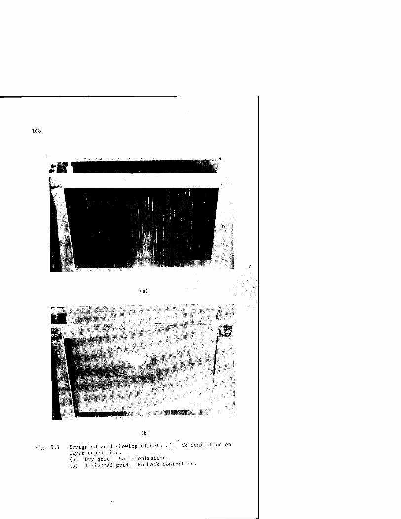
108
(a)
^V^*^.-f:-.> y ^ 9
m
(b)
Fig. 5.1 Irrigated grid showing effects of^, ck-ionization on
layer deposition. (a) Dry grid. Back-ionization. (b) Irrigated grid. No back-ionization.

109
irrigated. Tests are already under way to evaluate the possibility
of maintaining the grid wires free of powder by electrical and acous-
tical excitation. Such a system would lend itself very easily to
incorporation into a full scale commercial coating plant.
POWDERS
In addition to optimization of equipment, there is currently
tremendous scope for electrostatic optimization of powders. Most, if
not all, powders are currently formulated for optimum performance in
terms of flow, finish, etc; with little or no concern about electri-
cal parameters and how these might affect electrostatic behaviour.
That is, there is no electrostatic optimization. This must create a
weak link not just in powder behaviour, but in the behaviour and
...optimization of a complete coating system. For example, hardware may
?be painstakingly optimized, but to no purpose if the electrical
parameters of the powder to be used are not conducive to accepting
. charge.
"just how individual electrically insulating particles acquire charge
from airborne ions is not at all clear. A knowledge of the actual
ionic attachment sites, for example, would be of considerable impor-
tance as the first step towards optimizing charge acceptability.
This inherent difficulty of charging insulating particles was high-
lighted by Masuda in his work on elertr- jatic precipitation, which
ultimately led him to the develfj. .1. the boxer charger.^6
Rather than relying on unipolar charging of particles from a single
ion source, the boxer charger generates unipolar ions from what is
effectively two sources, with i Ic motion being in opposing direc-
tions. As insulating particles are made to pass through the ionized
region, ionic bombardment is effected over the entire surface area of
each particle. This has been shown to dramatically increase the
level of charging on individual particles.
Although an importap innovation, high charge level per particle
is not perhaps the ultimate requirement for powder coating applica- -3 -1 •
tions. A charge-to-mass ratio of, for example, 10 C.kg is not
difficult to achieve with corona charging. More important, and more
110
difficult to achieve, is this value for each and every particle in a
typical powder cloud emanating from a gun head. If the charging
efficiency is to be substantially improved, it is possible that a
completely new approach will have to be adopted for powder charging.
Present day equipment incorporates one of two principal charging
methods: corona charging or tribo-charging, and the relative advan-
tages of these two teehniques have been discussed in previous
chapters.
There is a third and potentially very attractive alternative to
these two methods: a method that has been adopted-and optimized to
suit the requirements of particle handling in electrophotographic
copiers. Conventional electro-copiers use a dry powder developer
which usually comprises two components: relatively large (100'\'200 \ira)
carrier beads and smaller (=30 ^m) toner particles,.attached to each
other by electrostatic forces resulting from interface charge
exchange. Typical of such charging mechanisms (tribo), the level of
charge exchange will be dictated primarily by the interface condi-
tions, and will offer little controllability. More modern developers
or toners are single component systems, where the complexities of the
carrier/toner interface are eliminated. No carrier particle is used,
and charging of the toner is effected by an artificially created
electric field. As the toner particles emerge from a dispenser, an
external electric field is created between the particles and the
substrate upon which they will alight. Particles are charged by
induction; an appealingly simple mechanism which offers infinite
controllability without the necessity of producing free ions.
Of course, electrical parameters have to be exactly right if this
technique is to work, and obviously toner manufacturers have concen-
trated on the electrical parameters of toner particles, as well as
on other requirements relating to copy performance and quality.
For electro-copiers, the resistivity of the toner has been arranged
to be field-dependent, and the same concept would be required for
powder coating applications.

Ill
For example, at the charging station the resistivity of the parti-
cles should be as low as possible for efficient charge exchange by
induction. However, on transfer to the substrate, whether it be a
photoconductor of a copier or a food mixer casing, the resistivity
should be as high as possible if adequate adhesion is to be ensured.
Careful attention to the chemical make-up of the toner has made
this possible for electro-copier applications. Although it is not
immediately obvious how this could be achieved for powder coating
applications, it is worth noting that such techniques do exist and
indeed are commercially exploited. That similar consideration might
be given to dry powder paint should not be discounted, provided
powder manufacturers are willing to invest in the future by initiat-
ing fundamental research investigations. Toner manufacturers have
'shown the way, and have proved that electrical manipulation and
■,:-'i ojitimization of solid particles can be achieved.
:,i; 'Induction charging in powder application equipment would certainly
■ be a very attractive proposition. The technique would offer infinite
controllability over charging levels, elimination of free ions and
operation at low charging voltage. Induction charging could be
easily adopted for use in either standard pistol-type or air-less
blade-type applicators (see Chapter 1).
The ultimate Teqiiirement in most coating installations is the
ability to deposit a high quality coating as thinly as possible.
Coating thicknesses of around 50 ym would often be considered very
desirable. However, with mean powder particle sizes being of the
order of 100 "^ 150 ym, such coating thicknesses have always been
beyond reach. Only very recently have new generations of ultra-fine
powder particles been commercially available, which for the first
time offer the possibility of thin layer deposition. Orgasol^^^ 3
nylon based material with mean particle diameter of 15 ym, is an
interesting example of this new generation of fine powders. In
addition to offering very small particle size, the particles are
almost spherical in shape, which can be very useful if theoretical
modelling of its electrostatic behaviour is to be attempted. As
112
with all fine particles, however, handling and manipulation will not
be easy. The maintenance of a constant flow rate through delivery-
hoses, for example, will be difficult to achieve, and compaction in
silos and hoppers invarably leads to erratic feed rates.
It would appear that problems associated with ultra-fine powders
are associated more with their mechanical rather than electrical
properties. A solution to the flow problems alone would undoubtedly
be a major contribution to the emergence of an entirely new approach
to powder coating.
MODELLING
Mathematical and computer modelling of electrostatic powder spray-
ing processes is becoming increasingly important since considerable
cost savings may be made by efficient design and operation of powder ;
spraying equipment. With the aid of computer modelling, coating ;;:
performance for different gun, booth and workpiece combinations can;, -f
be predicted. -'■■
In principle, modelling may be performed on a complete spray
system to include both the powder charging processes in the gun and
powder motion in the booth. The ease with which changes in equipment
geometry and operating conditions can be made makes computer simula-
tion a powerful design tool, and the ability of a simulation to pre-
dict performance opens up considerable opportunity for automation
9ft of a spraying process.
Computer-aided design (CAD) models are generally limited in com-
plexity only by the computer resources available. In contrast,
control simulations must be performed in real time during actual
spraying operations, and must ideally be as simple as possible.
However, control programmes may often be based on simplified CAD
simulations.
CAD SIMULATION
The movement of a charged particle from the gun head to a workpiece
occurs as a result of combined electrical and aerodynamic forces.
Over most of the volume of a typical spray booth, aerodynamic forces

113
will predominate. Close to the booth walls and workpiece surface,
however, electrical forces will become increasingly dominant.
Modelling powder motion involves calculation of both motive forces
repeatedly during the spraying process, since the distribution of
charged powder and free ions will be time dependent. These calcula-
tions require considerable computational effort and a number of
simplifications must be introduced in order to make the simulation
practical. The three-dimensional booth geometry may be approximated
to a two-dimensional axisymmetrical cylinder booth. Air-flow due to
the powder carrier air may be assumed not to vary significantly dur-
ing the spraying process. Figure 5.2 illustrates a typical flow
diagram of a powder spraying simulation programme.
Set geometry of booth and workpiece.
Calculate velocity.
Programme 1
Input physical parameters
Scale- velocity
■^Introduce ions and charged powder.
Calculate electrical forces.
Calculate ion and powder velocities.
Redistribute charge.
Test for onset of back-ionization.
End
Programme 2
Programme 3
Fig. 5.2 Typical flow diagram for powder coating programme.
114
It is structured as three discrete prograiimes, two of which are
pre-processes which set the booth geometry, calculate the air-flow
and set operational parameters such as charge-to-mass ratio. The
remaining progranime performs the simulations. The structure of the
programme is arranged so that for a fixed geometry, many different
simulations may be run with different operational parameters.
Preliminary results of electrostatic powder coating simulation
programmes have demonstrated how the presence of free ions in the
spray booth can enhance deposition rates over space-charge-free
situations, but on the other hand encourages the early onset of
back-ionization and degrades the quality of the coating finish.
Deposition has been shown to occur faster in dielectric booths than
in the traditional metal booth, with deposition rates increasing as
the dielectric constant of the booth decreases. Th_e ratio of work- '.
piece size to booth size has been found to be important:; the larger;-:,
the relative size of the booth, the faster the deposition - at least.,;.
in metal booths. The situation becomes a little more'feomplicated in :
plastic booths. Finally, the model has led to confirmation of the"
experimentally observed critical powder resistivity of 10 "^ 10 fim,
below which good adhesion is unlikely to occur.
115
Summary
This book has:, attempted to highlight some of the more important
practical implications of experimentally observed phenomena in
,. powder coating.
■. ■; Electrically charging isolated particles is not easy, and theoreti-
' C4I modelling of various mechanisms can become extremely complicated.
/Since the entire concept of powder coating relies on efficient
■particle charging, this has been dealt with in some detail but mathe-
matical treatment has been kept to an absolute minimum. It was felt
that the powder coating industry lacked a simple guide to powder
coating, and this monograph has been written with this very much in
mind. The chapter on measurement techniques should be especially
useful to plaht'-operators. There currently appears to be a serious
lack of appreSi^ion of how system behaviour may be assessed and
optimized from quite straightforward measurements. Equipment now
commercially available allows easy measurement of parameters such as
resistivity and charge-to-mass ratio. Plant operators are encouraged
to make more use of diagnostic equipment, where familiarisation with
both measurement techniques and actual numerical values of various
parameters will aid considerably system optimization.
Both hardware and powder are constantly under development, and it
is likely that a number of new innovations will have appeared by the
time this monograph is published. However, some predictions have
been made in the final chapter, including an analogy with formulation
techniques in the electrophotography industry. It is possible that

116
any further dramatic changes in powder coating technology will only
be achieved if and when a similar degree of sophistication is intro-
duced into powder formulation techniques. At the present time, there
is little or no consideration given to the electrostatic properties
of powder paint - a serious omission if complete system optimization
is to be achieved.
117
Bibliography
1. J. F. Hughes. 'Measurement techniques in powder coating installations'. Finishing Industries, lifheatland Journals Ltd. Vol. 4'.-No. 5.'- pp. 20-24. May 1980.
2. J. F. Hughes. 'Optimizing powder plant'. Finishing. Wheatland Journals Ltd. Vol. 6. No. 7. pp. 15-20. July 1982.
1^. J. F. Hughes. 'Future trends in powder'. Finishing. Wheatland ':■ Journal's .Ltd. Vol. 6. No. 11. pp. 17-21. Nov. 1982.
4. J. F. Hughes. 'Trouble shooting on powder installations'. Finishing. Wheatland Journals Ltd. Vol. 7. No. i- t-26.
April 1933.
119
References
1. B. D. Mdy'iej and J. F. Hughes. Inst. of Phys. Conf. Ser. No. 66. Elecrro-atiatics. Oxford, pp. 155-160. 1983.
2. M. M. Pauthenier and M. Moreau-Hanot. J. d'Physique et le Radium. Series No. 1 .■ pp. 590-613. 1932.
■3. P. S. H./Henry. Inst. of Phys. Conf. Ser. No. 11. Static : ; : Elecbrificatiori. pp. 195-199. 19 71.
•4. D. K. Davies^ Inst. of Phys. Conf. Ser. No. 4. pp. 29-36. 1967.
5. C. F. Gallo and W. L. Lana. Journal of Electrostatics. Vol. 2. pp. 145-150. 1976.
6. A. W. Bright. Journal of Electrostatics. Vol. 4. pp. 131-147. 1978. ,,
7. C. S. Athwai, P. F. Coventry and J. F. Hughes. Inst. of Phys. Conf.■■Ser. No. 66. Electrostatics, pp. 167-172. 1983.
8. G. Coe, J.' F. Hughes and P. E. Seeker. Brit. J. Appl. Phys. Vol. 17. pp. -885-890.
9. S. Singh and A. W. Bright. 3rd Int. Congress on Static Electricity. Grenoble, pp. lla-lle. 1977.
10. P. Lorrain and D. Corson. Electromagnetic fields and waves. Freeman (San Francisco). 1970.
11. J. F. Hughes and Y. C. Ting. IEEE/IAS. 12th Annual Meeting. Los Angeles, pp. 906-909. 1977.
12. J. F. Hughes and Y. C. Ting. 3rd Int. Congress on Static Electricity. European Federation of Chemical Engineering. Grenoble. 1977.
120
13. A. W. Bright, R. P. Corbett and J. F. Hughes. Electrostatics. Engineering Design Guide No. 30. Oxford University Press. 1978.
14. U.K. Patent No. 8320654.
15. B. D. Moyle and J. F. Hughes. IEEE/IAS. 17th Annual Meeting. San Francisco, pp. 1191-1195. 1982.
16. J. F. Hughes and A. W. Bright. Trans. IEEE and Industry Applications. Vol. lA-15. No. 1. pp. 100-104. 1979.
17. Available from Industrial Development (Bangor) Ltd., UCNW, Bangor, N.Wales. ";
18. Available from Mindon Engineering Ltd., Nottingham, U.K.
19. Available from Electrostatic Equipment Corporation, Connecticut, U.S.A.
20. Available from Volstatic Coatings Ltd., U.K.;'
21. J. F. Hughes private communication.
22. W. Kleber et al. Elektrostatisches Beschichten;: Vom. 24. bis. 27. Hochschule fur Verkehrweren. Friedrich List. Dresden, pp. 109-116. 1978.
23. S. Masuda et al. IEEE/IAS 12th Annual Meeting. Los Angeles. pp. 887-891. 1977.
24. Available from Sankyo-Denkyo. Japan.
25. J. F. Hughes. Private communication.
26. S. Masuda. IEEE/IAS. 15th Annual Meeting. Cincinnati. pp. 904-911. 1980. -
27. Available from ATO-CHEM, Serquigny, France.
28. N. J. Diserens et al. Journal of Electrostatics. Vol. 5. pp. 169-182. 1978.

Index
121
adhesion; 31 ■■.
back-ionization 20, 22, 23, 27, 30, 63,.76, 94, 98
bi-polar 2! ;'' •. .
blade-coater ■' 79
;booths 56,- 61,'69, 82, 83, :-V:;S6, 102 '■•"'
charge-to-mass ratio 29, AC, 45, 53, 103
corona 1, 2, 28, 62, 69, 92, 106
cyclo-gun 76, 77
disc 80, 81
earthing ' 9.9 ,
electric curtain 87, 88
electric field 17, 29, 35, 44, 54, 58, 72
electrometer 40
electronegative 4
Faraday cage 19, 41, 67
field mill 54, 58, 59
fluidised bed 61, 64, 66
Gauss' Law 19
guard electrode/ring 32, 33
induction 12, 14
ion wind 15, 16, 79
ions 16, 23, 28, 72
irrigated grid 43, 107, 108
jigs 99, 100, 101, 102
mobility 73, 79
modelling 112
optimization 91, 105
orange-peel 25, 27, 106
Pauthenier limit 6, 7, 8
permittivity 35, 36
pin-holing 25, 27
pistol 61, 70
potential 47, 97
powder 109, 111
relaxation 30
resistivity 29, 32, 93, 95, 103, 110
resistor chain 49, 50
time-constant 35
tribo 8, 9, 11, 12, 28, 63, 75, 92, 106, 110
wrap-around 19, 20, 52