this document has been reproduced from … · supplementary notes ... glycidyl ether epoxy chosen...
TRANSCRIPT

N O T I C E
THIS DOCUMENT HAS BEEN REPRODUCED FROM MICROFICHE. ALTHOUGH IT IS RECOGNIZED THAT
CERTAIN PORTIONS ARE ILLEGIBLE, IT IS BEING RELEASED IN THE INTEREST OF MAKING AVAILABLE AS MUCH
INFORMATION AS POSSIBLE
https://ntrs.nasa.gov/search.jsp?R=19800005003 2018-07-09T02:10:44+00:00Z

NASA TECHNICALMEMORANDUM
'N,1' ^A TIA-78241(NASA-TM-78241) DEVELOPMENT AND EVALUATIONOF AN ABLATIVE CLOSEOUT MATrRIAL FOR SOLIDROCKET BOOSTER THERMAL PROTECTION SYSTEM(NASA) 46 p HC A03/MF A01 CSCL 11G
G3/27
DEVELOPMENT AND EVALUATION OF AN ABLATIVE
CLOSEOUT MATERIAL FOR SOLID ROCKETBOOSTER THERMAL PROTECTION SYSTEM
N00-13250
Unclas46331
By W. J. PattersonMateriels and Processes LaboratQ:-y
October 1979
NASA
George C. Marshall Spice Flight Center
Marshall Space Flight Center, Alabama
MSFC - Form 3190 (Rev June 1971)

Tlrt-H)"CAI 000!'107 Wr AMMAbf1 T19'f Ir MAe-=
1. REPORT N0,
NASA TM -75241Z, GGVEg HM[NT ACCESSION NO.
—_
—3. RECIPIENT O S CATALOG NO,
Q, TITLE AND SUBTITLE
Development and Evaluation of an Ablative CloseoutS. REPORT DATE
October 1979Material for Solid Rocket Booster Thermal Protection 6. PERFORMING ORGANIZATION COOT
System7, AUTHOR(S) S, PERFORhANG ORGANIZATION REPOR f 1t
W. J. Patterson9. PERFORMING ORGANIZATION NAME AND ADDRESS 10, WORK UNIT, NO,
George C. Marshall Space Flight Center 11, CONTRACT OR GRANT NO,
Marshall Space Flight Center, Alabama 3581213, TYPE OF REPORT & PERIOD COVERED
12. SPONSORING AGENCY NAME AND AQDRE$$
Technical MemorandumNational Aeronautics and Space AdministrationWashington, D. C. 20546 14, SPONSORING AGENCY CODE
15. SUPPLEMENTARY NOTES
Prepared by Materials and Processes Laboratory, Science and Engineering
16, ABSTRACT
A trowellable closeout/repair material designated as MTA-2 (MarshallTrowellable Ablator) has been developed in-house at Marshall Space Flight Centerand has been evaluated for use on the Solid Rocket Booster. This material is com-posed of an epoxy-polysulfide binder and is highly filled with phenolic microballoonsfor density control and ablative performance. The MTA-2 material has beenevaluated by mechanical property testing as well as thermal testing in a wind tunnelto simulate the combined Solid Rocket Booster trajectory aeroshear and heatingenvironments. This material is characterized by excellent thermal performance andhas been used extensively on the Space Shuttle STS-1 and STS-2 flight hardware.
17. KEY WORDS Ia. uiJTRIBUTION STATEMENT
Unclassified-Unlimited
19. SECURITY CLASSIF. (or this report) 20, SECURITY CLASSIF. (of this Page) 21. NO, OF PAGES 22, PRICE
Unclassified Unclassified 46 NTIS
1
MSFC - Form 3292 (Rev December 1970 For sale by National Technical Itiforntaiiion Service, Springfield, Virginia 22 15 1
y

ACKNOWLEDGMENTS
The author acknowledges the contributions of Mr. Roger Harwell,E1-134, for initial formulation assessment, Mr. Bill White, EI-133, for con-tinuing test panel preparation and evaluation, and the Thermal AnalysisBranch, EP44, under whose cognizance the thermal testing was performed.

i
1
TABLE OF CONTENTS
Page
I. INTRODUCTION ............ . .... . ... . . . . ... .. .. .... .. .. to 1
II. APPROACH .................. a ....... a .................... 2
A. Formulation Development 2B. Closeout Formulation Assessment ..................... 7
III. EVALUATION TESTING ............ . .. . ... . .............. 15
A. Thermal Property Assessment., ....................... 15B. Physical /Mechanical Property Assessment .............. 35
IV. CONCLUSIONS ........................................... 36
REFERENCES.................... .. . . . . . . . . . . . . . . . . . . . . . . . . . . . . . 39
PRECEDING PACE FAT,, NK NOT FII MMY
s
Y

LIST OF ILLUSTRATIONS
Figure Title Page
1. Effect of tin octoate accelerator on cure rates ofcloseout formulations ........0.0.0.....0 ............... 6
2. Thermal /vacuum closeout specimen ..................... 8
3. Post-test thermal/vacuum specimen, MTA-2( Formulation A) ......................0000............. 9
4. Post-test thermal/vacuum specimen, MTA-2( Formulation B) ....................................... 10
5. Post-test thermal/vacuum specimen, cork-filledepoxy formulation ..................................... 11
6. Post-test thermal/vacuum specimen, aliphatic aminecured MTA formulation ................................ 12
7. Flatwise tensile strength specimen of closeoutmaterial ............................................... 14
8. MTA-2 closeout panel buildup sequence: substrateready for closeout material ...........0 ................ 17
9. MTA-2 closeout panel buildup sequence: initialapplication ............................................ 18
10. MTA-2 closeout panel buildup sequence: finalsurface finishing of closeout ........................... 19
11. Pre-test ,^MGF panel of MTA-2 closeout material ....... 20
12. Post-test, MHGF panel of MTA-2 closeout material ...... 21
13. Post-test MHGF closeout panel cross-section ........... 22
14. Post-test MHGF panel: closeout thicknessassessment ............................................ 23
15. Post-test MHGF panel: closeout thicknessassessment ............................................ 24
16. Pre-test MHGF panel: closeout configurationassessment ............................................ 25
iv
w

LIST OF ILLUSTRATIONS (Concluded)
Figure Title Page
17. Post-test MHGF panel: closeout configurationassessment ............................................. 26
18. Pre-test MHGF panel: MTA-2 closeout on MSA-1spray ablator ........................................... 28
19. Post-test MHGF panel: MTA-2 closeout on MSA-1spray ablator .......................................... 29
20. Post-test MHGF panel: MTA-2 closeout on MSA-1spray ablator .......................................... 30
21. Pre-test MHGF kick attach model with MTA-2fastener insulation ..................................... 31
22. Post-test MHGF attach ring model with MTA -2fastener. insulation ..................................... 32
23. Pre-test AEDC instrument island model withMTA-2 closeout ......................................... 33
24, Post-test AFDC; instrument island model withMTA-2 closeout ......................................... 34
25. Strain compatibility specimen simulating MSA-1ablator with MTA-2 closeout • ........................... 37
v
rr,

LIST OF TABLES
Table Title Page
1. Lap Shear Tensile Strength of Candidate CloseoutResin Formulations .... . ...0.0.0...0 ................... 4
2. Test Formulations l'or Cure Acceleration Studies........ 5
3. Candidate MTA-2 Closeout Material Compositions........ 7
4. Thermal/Vacuum Test Results for CandidateCloseout Formulations .................................. 13
5. Flatwise Ten wile Strengths of Candidate CloseoutFormulations ........................................... 13
6. Cure Time Versus Temperature for MTA -.1
Closeout Formulation A ................................. 15
7. MTA-2 Thermal Test in Simulated SSME EnginePlume Impingement Environment ....................... 35
8. Flatwise Tensile Strength Assessment Datafor MTA-2 ............................................ 35
vi
Y

TECHNICAL MEMORANDUM
DEVELOPMENT AND EVALUATION OF AN ABLATIVE CLOSEOUTMATERIAL FOR SOLID ROCKET BOOSTER THERMAL
PROTECTION SYSTEM
I. INTRODUCTION
Early in the development of the Thermal Protection System (TPS)for the Solid Rocket Booster (SRB) it was recognized that an easilyapplied, trowellable closeout/repair material would be required to augmentthe primary TPS materials, MSA--1 1 and sheet cork. This material mustserve to fill in gaps or discontinuities in the primary TPS and must alsobe a!Dplicable in place of the primary TPS in small, poorly accessibleareas.
Finally, the closeout material must be useful to repair damagedareas in the primary TPS. The initially defined closeout material goalsfor SRB flight hardware are summarized as follows;
1) Thermal/ablative performance -- equivalent to surroundingprimary TPS
2) Substrate adhesion -- minimum 100 psi flatwise tensile strength
3) Strain compatibility -- no material failure at a minimum substratestrain of 1.4 percent.
4) Processing characteristics — readily hand trowellable , thixo-tropic, long working life, cure in 24 h at 75°1 in thick sections
5) N( n-flammable per NHB 8060.1A
6) Compatible with primary TPS, topcoats, and substrate paints
7) Removable with high pressure water without substrate damage.
An in-house program was then initiated to develop and qualify sucha material for flight hardware application.
1. MSA-1 is the Marshall Sprayable Ablator which is applied to nosecap, frustum, and forward skirt elements while sheet cork is appliedto the aft skirt.
+c

II. APPROACH
The basic approach to development of a closeout material was toutilize the excellent adhesive strength and room temperature cure charac-teristics of epoxy resins, And modify this system with polysulfYde toimprove flexibility and strain compatibility.
A. Formulation Development
The bisphanol A - glycidyl ether epoxy chosen for this develop-ment was Epon 828, a commercial liuid epoxy prepolymer having anumber average molecular weight (0 n) of 369 and an epoxide equivalentweight of approximately 185, assuming difunctionality of the terminalepoxide groups:
1113^113
C11^CI1CII 20 no ---n4 -- O C11 2CI1CII O I --C -n0 OCi1 C11CII2
CII 3 1 n 0113o OH O
Epon 828 Epoxy Prepolymer
Similarly, the polysulfide prepolymer has a M n of 1000 and is
difunctional with respect to mereaptan terminating groups;
HS CH 2CH 2OCH 2OCH 2CH 2-S-S-}— C112CH2OCI-I2OCH2CH2-SHn
1,P-3 Pol sulfide Pre polymer
The mercaptan group is nucleophilic in nature and will slowlyattack the primary carbon of the oxirane ring:
1.1 '~%**% . S H + CH 2, H rv^---►
C I C Ii H —
G.oH o-°
-S - CH2CH—^OH
t:
2
t
tl

However, the reaction rate at room temperature is low and onlyproceeds at a practical rate by the additiot', of a base to accept the pro-ton and generate the more strongly nuclecphilic mereaptide anion. Inthis study, several organic bases or amines were investigated to serveas crosslinking agents for the epoxy prepolymer and to promote theepoxide-mereaptan chain extension reaction.
The amines which were screened as potential catalysts or cross-linking agents are as follows;
1) (CH 3 ) 2N CH2 —5—
Of N (C1I3)2
611 2 N (CH 3 ) 2
Tris (dimethylaminomethyl) phenol (DMI'-30)
11 N.^ ,N I12) 2 2 If 2N—gQ _C112-00 —N112
m - Phenylenediamine M(MPDA) ethylenediiiniline(MDA)
(This was used its 70/30 mixture NIPDA/MDA, availablecommercially its Shell Z)
11 11
3) H 2 N CH 2CH 2 N C11 2Cli 2 N CH 2CH 2 Nil 2
Triethylenetetramitie (TETA)
4) 11 2N -- (D_ Cli 2 -- G) —NH 2
Bis (4 - aminocyclohexyl) methane (PACM-20) .
The tertiary amine (1) acts as tin anionic initiator for ring =opening poly-merization via the oxirane rings of the epoxy resin, while amines (2)through (4) possess active hydrogen functionality, and serve its authen-tic crosslinking agents for the epoxy prepolymer.
Sulastrate adhesion was considered it parameter for thecloseout naterial, so the lap shear tensile adhesive strength of thecandidate formulations was utilized as an initial screening test. Weightratios of epoxy /polysulfide of 1 / 1 were reported [ 1, 2 1 to provide it
aY
3
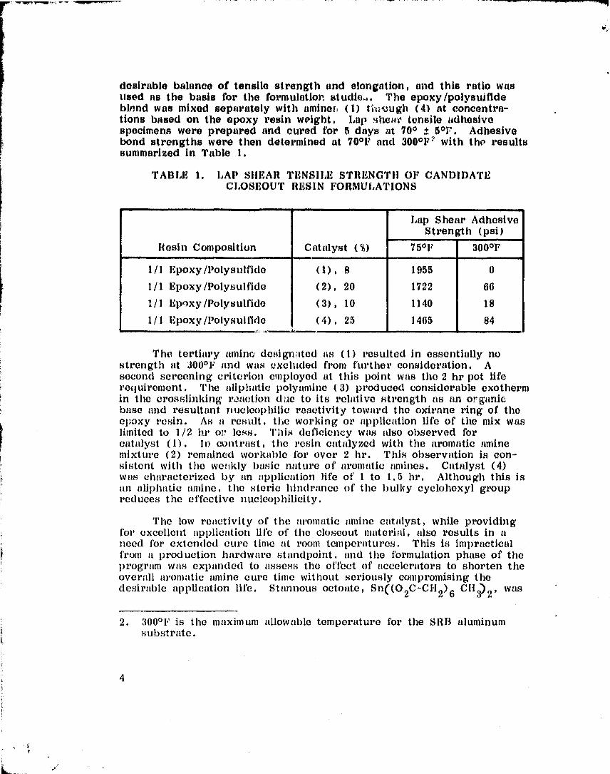
desirable balance of tensile strength and elongation, and this ratio wasused as the basis for the formulatior. studio..,. The epoxy /polysui fidebinnd was mixed separately with amines, (1) tlu uugh (4) at concentra-tions based on the epoxy resin weight, Lap 4h014V tonsile adhesivespecimens were prepared and cured for 5 days at 70 0 ± 5 0F. Adhesivebond strengths were then determined at 70O F and 300°F' with the resultssummarized In Table 1.
TABLE 1. LAP SHEAR TENSILE STRENGTH 01 7 CANDIDATECLOSEOUT RESIN FORMULATIONS
Resin Composition Catalyst M
Lap Shoat, AdhesiveStrength (psi)
75°F 300°F
1/1 Epoxy /Poly s u Ifide (1). 8 1955 01/1 Epoxy /Polysul fide (2), 20 1722 661/1 Epo xy/Polysulfide (3), 10 1140 18
1/1 Epoxy /polysulfide (4). 25 1465 84
The tertiary amine designated as (1) resulted in essentially nostrength tit 3000F and was excluded from further consideration. Asecond screening criterion employed at this point was the 2 hr pot fiferequirement. The aliphatic polyamine (3) produced considerable exothermIn the crosslinking roaction (Uic to its relative strength its tin organicbase and resultant nucleophilic reactivity toward the oxirane ring of theepoxy resin. As a result, the working or application life of the mix waslimited to 1/2 hr oii less. `Phis deficiency was also observed forcatalyst (1). In contrast, the resin catalyzed with the aromatic aminemixture (2) remained workable for over 2 hr. This observation Is con-sistent with the wcokly basic nature of aromatic amines. Catalyst (4)was characterized by an application life of I to 1.5 hr. Although this istin aliphatic amine, the steric hindrance of the bulky cyclohexyl groupreduces the effective nucleophilicity.
The low reactivity of the aromatic amine catalyst, while providingfor excellent application life of the closeout material, also results in itneed for extended cure time tit room temperatures. This is Impracticalfrom a production hardware standpoint, and the formulation phase of theprogram wits expanded to assess the effect of accelerators to shorten theoverall aromatic amine cure time without seriously compromising thedesirable application life. Stannous octoate, Sn((O 2 C-CH 2)6 CH 3) 2 ' was
2. 3000 11 is the maximum allowable temperature for the SRB aluminumsubstrate.

chosen for theiia tests bused on its selective accelerating effect on therates of certain nucleoplillic displacements such as the amine /oxtraneren-tion. The rel %Jive rate enh ,,.incement due to the accelerator wasmonitored by viscosity ch-inge as a function of time. The test formula-t1ood tire tabulated In Table 2 and the viscosity data are summarizedgraphically In 141guro 1.
TABLE 2. TEST FORMULATIONS FOR CURBACCELB RATION STUDIES
Formulation Hpon 828 1.11- 3 811011 Z Tin Octonte
1 50 50 10 0
2 50 50 20 0
3 50 50 20 1
4 50 50 20 2
5 50 50 to 3
it. Numbers in
each column tire parts by weight
.IAs illustrated In
F gure 1, the visco^,Itics of formulations 4 and 5are reasonably independent of time for the first 2 fir (providing forextended working life) but increase sharply
from that point
on to resultIn
it moderately efficient cure rate. After
48 fir, formulations 4 and 5had cured to a tack-fret, tough, crossfinked solid.
The next stage In formulation development was selection of it lowdensity filler to reduce the overall closeout material density to 30 to 35
lb/ft 3 and provide acceptable thermal/ablative protection. The candidate
filler materials were phenolic microballoons, glass microballoons, lindground nork. These fillers were formulated into test closeout mixes todetermine maximum filler loading consistent with acceptable trowellingcharacteristics. This wits found to be 40 percent, 30 percent, and 15percent by weight (based on combined resin weight, 828 + LP-3) for thephenolic, glass, and cork fillers, respectively. The phenolic-filled for-mulation provided lower density, case of hand application (trowelling),non-slumping (thixotropic) on vertical surfaces, and cure in thicksections (up to 2 in.) without cracking. Tius, the most promising for.-mulation at this stage of development wits the phenolic microballoon filled,aromatic amine/tin octoate cured, epoxy- polys ulf,.' de material representedby the compositions shown in Table 3, and the general formulation wasgiven a tentative designation of Marshall Trowellable Ablator, MTA-2.
5

0 2 4 6
IMULATION 1
8
DN 6
PION 3
ION 2
N ^
sW
W
9
8xCa
TIME (hr)
Figure 1. Effect of tin octotate accelerator on cure matesof closeout form ul tit ions.
6
r
L

TABLE 3. CANDIDATE MTA-2 CLOSEOUTMATERIAL COMPOSITIONS
ComponentComponent Parts by Weight
Formulation A Formulation B
Epon 828 50 50
LP-3 50 50Shell Z 20 10Tin Octoate 2 3
Phenolic Microballoons 40 40
B. Closeout Formulation Test and Evaluation
The primary screening parameters for the candidate closeoutmaterial were thermal/vacuum exposure and flatwise tensile testing whichfocused primarily on the MTA formulations. The thermal/vacuum testspecimen consisted of 1/2-in. cork bonded to aluminum substrate. A2-in, wide groove was cut to the substrate to receive the closeoutmaterial. The thermal exposure consisted of a con^Aant r,idjant heatingenvironment of 15 Btu/ft 2_ see for 130 see, with a simultaneous pressuredecay to simulate the SRB ascent environment. The specimens wereinstrumented to monitor substrate temperature. Figure 2 illustrates thethermal/vacuum closeout specimen.
The primary determinants in this type of test were chat, depth(recession) and char integrity. The goal was to obtain a recession rateno greater than tho surrounding primary TPS and to produce a tough,stable char to enhance insulating quality. The MTA formulations identi-fied in Table 3 performed quite well in this test as indicated in Figures3 and 4. These figures verify that the closeout material char depthapproximates that of the surrounding cork TPS. By comparison, therecession rates of a commercial cork-filled ablator ( Fig. 5) and thealiphatic amine cured ablator (Fig. 6) were substantially higher assummarized in Table 4.
The flatwise tensile strength measurements were performed at 75°Fand 300°F utilizing a specimen configuration illustrated in Figure 7 andpulled in tension to failure on an Instron tester. The failure mode wasconsistently cohesive (bulk failure in the material) at both temperaturesfor the candidate formulations, as summarized in Table 5. Again, thebeneficial effects of the aromatic amine crosslinking agent are manifestedin the 300°F flatwise tensile strength.
Y

EC)Q)
c
IM
Cv
cl;
ILI

CC
0
C4
, AW
E
E
Cj
tA0a
W
U
9

.0
G
UO
U
U
Oa
a^+^ww..^......... __, c,
w
aC
F.
^3r
NQH
0

aEc,
w
k
v
V
wxc.0ur_
EUUa
Eaau
Ea^
a^
0a
a);,aho
0
w
TIIE1 ^
nit1..
ovi

0
Ec,0
ZE-^
c.aU
U
U
ti
CO
CU
UU
e O,s
EOaUCy
CZ
EI,U
Ui
O
cc
U
G.,
12
y
v

TABLE 4. THEPMAL/VACUUM TEST RESULT., FOR CANDIDATECLOSEOUT FORMULATIONS
FormulationAT(OF)
Char Depthb(percent) Char Condition
MTA (A) 113 40 Tough, stable char
MTA (B) 118 50 Tough, stable char
Aliphatic Amine 119 60 Weak, loose charCured MTA
Cork Filled Epoxy 212 90 Very fragile char,substrate visible
a. AT = Substrate temperature rise above 75°F.
b. Percentage of total specimen thickness converted to char,based on original thickness of 1/4 in .
TABLE 5. FLATWISE TENSILE STRENGTHS OF CANDIDATECLOSEOUT FORMULATIONS
Formulation
Flatwise Tensile Strength (psi)
75°F 300°F
MTA-2 Formulation A 625 72
MTA-2 Formulation B 510 49
Aliphatic Amine Cured MTA 386 17
Cork-Filled Epoxy 404 24
The cure time characteristics of the candidate MTA-•2 closeoutformulations were monitored by hardness techniques. Shore hardnessmeasurements were made as a function of time at a given temperature toestablish minimum cure time, defined as the time required to reach anessentially constant hardness. The MTA-2 formulations A and B reacheda cured condition after a minimum of 24 hr at 100 0 to 105°F, as opposedto 48 and 72 hr for formulations A and B, respectively, when cured at
13
- Y

;r
roE
«J00v0V
w.O
CUEUUa
c
a^
v
^U
REPRODUCIBILITY OIL` TILLORIGINAL PAW', I POOL
14

temperatures as low as 65°F. At cure temperatures as low as 40 0F, thespecimens required a minimum of 144 hr to reach an equivalent hardness.In each case. the adequacy of curd was verified by flatwise tensilestrength measurements (minimum 140 psi requirement). The cure time/temperature data for the MTA-2 formulation A are summarized in Table 6,
TABLE 6. CURE TIME VERSUS TEMPERATURE FOR MTA-2CLOSEOUT FORMULATION A
Cure Time(hr)
Temperature(°F)
Flatwise Tensile Strength(75°F)
24 40 Material soft, uncured
48 40 Material soft, uncured
72 40 Material firm, partiallycured
144 40 242 psi
24 70 82 psi
48 70 466 psi
24 85 189 psi
24 100 480 psi
Ill. EVALUATION TESTING
A. Thermal Property Assessment
Based on the development test results discussed in the precedingsection, the decision was made to go into detailed thermal testing withthe MTA-2 formulation (A) , now designated simply as MTA-2, althoughformulation (B) was also carried through portions of this test phase.The principal thermal testing was performed in the MSFC Modified HotGas Facility (MHGF) . The MTA-1 assessment included, testing as acloseout /repair material for both MSA-1 primary able ",or (for forwardSRB elements with lower heating rate) and for sheet cork on the SRBaft skirt where a higher thermal environment is experienced. TheMHGF wind tunnel test panels for cork closeout evaluation were approxi-mately 21 by 27 in. Sheet cork, 1/2-in. thick, was bonded to the
15

aluminum substrate and 2--in. grooves were milled down to the substrateto produce a closeout test pattern in the cork. Bolts were located alongthe grooves to simulate fasteners on the SRB flight hardware. Thesewere encapsulated with PR-1422 polysulfide sealant and fitted with asealant cap. This again reflects the flight hardware fastener configura-tion. The closeout material was applied to the test panel and allowed tocure. This panel buildup sequence is illustrated in the series of Figures8, 9, and 10. The panel was instrumented with thermocouples on thedummy fasteners and on the substrate. This test panel was configuredto allow simultaneous test of two closeout materials, each occupying onehalf of the panel. Figure 11 illustrates the final pre-test condition withFigure 12 showing the effects of a 60-sec run in position 3 of the MHGFwith a heating rate distribution of 20 to 44 Btu/ft 2-see from leading totrailing edge of the panel. As indicated from Figure 12, the MTA (tipperhalf of closeout pattern) performed quite well with adequate char remain-ing to provide thermal protection to the fasteners and over all closeoutareas. No substrate or fastener temperatures above 90°F were observed.The lower half of the closeout pattern was MTA cured with the aliphaticamine, PACM-20. The higher recession rate is obvious from exposure ofthe simulated fasteners, and is believed to result from the relativelypoorer char stability typically conferred by aliphatic amine cured systems.A further example of the utility of MTA-2 as a cork closeout is illustratedby Figure 13. This specimen is a segment of a MHGF panel run underconditions described earlier. The cross section vividly shows the closecorrespondence of cork and MTA-2 recession rates, which constituted acritical goal of this development program.
In this phase of the development testing, several MHGF runs weremade to define appropriate closeout configuration and thickness, Forexample, in Figure 14 the MTA-2 closeout material was applied flush withthe cork in the circular repair simulation patterns, and just thick enoughto cover the fastener caps (approximately 1/8 in. coverage) with essen-tially no ramping of the MTA-2 out onto the adjacent cork on the leadingedge. As a consequence, the repair area survived quite well (no inter-ference heating effects) , but the fastener area acted as sufficient pro-turberance to cause high localized heating and expose the fasteners.Two alternate configurations were then evaluated. In the first of these(Fig. 15) , the MTA-2 was built up to a closeout thickness that alloweda minimum of 1/2 in. above the top of the fastener and ramped down4 in. from the fastener center line onto the adjacent cork surface. Thesecond configuration involved cork strips on either side of the fastenerrow forming a trough which was filled with MTA-2 level with the cork.Also the leading edge was ramped down at 30 degrees to the adjacentcork (Fig. 16). The post-test photograph (Fig. 17) shows adequateretention of closeout material to protect the fasteners (fastener on near
16
' r„
r
_
t

or,
TTTrj
PAGE17
c.
Ul)

v
aaro
v^ a
a0
a
U
a
a0v
0UN
C.
.ti
Ltr
18
c0
''Y

4.
uw0Ct.c
wvuw
a
ro0
vu
a^a
c^;r
aa
aea
v;0vN
r
O
L.
a^A
Y TTrI. ^, '^s t ^'
UitI^;I:^.A1 1
c
19
r

v
E
0Z
apt
N
4.O
OCa
v
r
v
a
vc,
20
r

rEr
0
m0UN
I
Q.
rWO
UCTS
f1.
W
r
i
t+
rIrO
CV
N
^ryr_
O1J.ti
:L
T TIIEGTr^I [ ,IS I5 p O'At
ORIGIN nL I AG„
21
Y
r%^

U.r
Ua)
I
O
U
C)OCJ
a
0al
0U
(1.V
t
OI
U:
OQ.
M
Sr
.N
W
22
Y

a^c.
v
c^
xU
UOU
U
CL
VT
i
^A
c
cvE
REPRODUCIP TT,TTY OP THE
ORIGINAL PAGE IS POOR
23
.1'
1

U
6A
q LL+
t;vE
a^
c^
a^
c'
nUOU
NCcz
II,
Gr.
Z.e•
cn
U
I
O
24
r

U)V)a^U.
RS
O
c,
pCU
O
U
awc^z
a^
a
a^s,
w
r
vE
1111TRODUCIBIT.ITY Or TH'ORIGINAL PAGE IS POOR
25

:! f;
^ar
G
CO
COtiGbAwoGU
G
O
V
O
aw
0a
a^
Uw

edge of panel was exposed deliberately from pre-test panel fitting opera-tion). Both closeout configurations' performed successfully with nosignificant substrate heating.
To evaluate the use of MTA-2 with the MSA-1 orimary ablator,MHGF pr.nels sprayed with MSA-1 and coated with white topcoat weremodified with MTA-2 closeout/repair areas as shown in Figure 18. Thesepanels were run in position 2 of the MHGF for 60 sec (heating rate rangefor position 2 is 8.2 to 20 Btu/ft 2_sec). The five repair areas arevisible in Figure 19 as the dark circles. The MTA-2 recession was lessthan that of the surrounding MSA-1, although it is not obvious from theangle of the photographic view. The corresponding Figure 20, in whichthe char layer on this panel was removed down to virgin ablator, veri-fies the acceptable performance of the MTA-2.
The closeout material is expected to have a number of specializedapplications on protuberances where high neroshear-induced heating ratesare found. The MTA-2 was tested in two such protuberance configura-tions which further reinforced the confidence in its thermal/ablative per-formance. Figure 21 shows an SRB kick ring model in which MTA--2was used to protect fasteners on the top surface of the model. After a17,1-sec run at 30 to 40 Btu /ft 2-sec, the MTA-2 wig s still intact and pro-vided adequate thermal protection for the fastener (Fig. 22) . In thesecond protuberance application, MTA-2 was utilized to ramp up fromadjacent cork TPS to the top of an instrumentation island (the MTA-2 isshown painted white with the surrounding cork in Fig. 23). This speci-men was run at the Arnold Engineering Development Center wind tunnel,Tullahoma, Tennessee, and exposed to 8.6 to 13.5 Btu/ft 2-see for 107see. The post-test condition shown in Figure 24 indicates adequate charstability and ablative performance.
An extremely severe SRI3 thermal environment is encountered forvery short times (less than 10 sec) as the separated SRB falls backthrough the Shuttle main engine exhaust plume. Special tests were con-ducted at Aerotherm, Inc. , Mountain View, California, in which theMTA-2 was exposed to severe heating in the range of 72 to 138 Btu/ft 2-see. The results, summarized in Table 7, indicate that even at 136
Btu /ft 2-sec, the sample survives approximately 9 sec before the 300OFsubstrate limit is reached.
3. Variations of these configurations were ultimately implemented on theSRB aft skirt in areas of high heating rates.
27
r
^r

28
co
"'Ib
d
a
0UC1
d
E-4
C
Uc^
LL
V
i
taia
U
0

cc
c.o,
^r
0
(,J
W
V.
C
Uc^
F-
wC7
i
i
Oa
c^
s,0bC
w
0
REPRODUCIBILITY Or Tlil-.ORIGINAL PAGE' IS Powt 29

s.04.c^
Ac^
c^c.drp
UO
a0
«Ja
0UGV
Q
H
i
C)r.CZ
awT
W
LCOa
ca^
a
•r^•y
W
3 L'
•YY

rUU
i
^f
E-i.yrC.i
ErU
xUx
VwG
UC.a
GV
Uf.
bC
w
0
r^1',I'1tODL1 L71;LLI'I'^ op THE()RIGINAL YAG1% IS
r

0
a
uca,
w
ub0E
b,cc
u
.r
wV
t
as
n
4
i
32

Figure 23. Pre-test AEDC instrument islawi model withNITA-2 closeout.
REPRODUCIBILITY u.' 'I'IILORIGINAI, PACE IS POOTZ
. rr

0
u
F
r.
C
.r
C
.nC
C.inw
0a
4C11
d
Lr.
34
r

TABLE 7. MTA--2 THERMAL TEST IN SIMULATED SSME ENGINEPLUME IMPINGEMENT ENVIRONMENT
Heating Rate Back Face
2Exposure Time Temperature
Test (Btu /ft -see) (sec) (OF)
1 72 16 2852 77 21.1 217
3 136 9.4 3074 138 5.9 140
B. Physical/Mechanical Property Assessment
The following properties of MTA-2 were determined as part of theoverall qualification assessment.
1. Flatwise tensile strength. Test specimens 2 by 2 in. were cutfrom a previously cured 1/2-in. thick trowelled test panel. Flatwisetensile specimens were prepared and pulled in the Instron tester at across head speed of 0.050 in. /min, at 75°F and 300°F. Peak load atbreak was used to determine flatwise tensile strength. The final quali-fication values for MTA-2 are given in Table 8, and represent an aver-age of 4 individual data points in each case.
TABLE 8. FLATWISE TENSILE STRENGTH ASSESSMENTDATA FOR MTA-2
FormulationCure Time
(hr)
CureTemperature
(°F)
Flatwise TensileStrength (psi)75°F 300°F
MTA-2 (A )a 48 70 425 52MTA-2 (A) 24 100 565 39MTA-2 (B) b 72 70 495 49MTA-2 (B) 24 100 601 55
a. 50 parts 828/50 parts LP-3/20 parts Shell Z/2 parts tin octoate.
b. 50 parts 828/50 parts LP-3/10 parts Shell Z/3 parts tin octoate.
.
35
V_ r

2. Density. Density was determined on 2 by 2 by 1/2 in. thicktrowelled specimens by calculation from weight and volume measurements.3The average density based on 4 individual determinations was 30.5 lb/ft
3. Flammability. A set of three flammability specimens was pre-pared by trowelling 2-in, thick MTA-2 onto 12 by 2 1/2 in. aluminumsubstrates. The specimens were tested in accordance with NHB 8060.1A,Test 1, for upward flame propagation in air. The samples self-extinguished within 6.5 in. (specification requirement is 6 in.). TheMTA-2 was judged acceptable by material useage agreement.
4. Moisture Absorption. Specimens of MTA-2, 2 by 2 by 1/4 in.thick were weighed on an analytical balance, totally immersed in distilledwater for 24 hr, dried of surface moisture, and reweighed. The average(4 specimens) weight gain was 2.27 percent. These specimens were thenbonded into flatwise tensile specimens and tested at 75°F. An averagestrength of 512 psi was measured, which represents a 9.4 percentdecrease attributable to water exposure based on the intial strength datacited in Table 8.
5. Strmn Compatibility. The strain compatibility of the MTA-2closeout material1 was determined in accordance with the protocol andprocedure in Reference 3. The simulated MSA-1/MTA-2 closeout wasmade in the gage section of the tensile specimen shown in Figure 25.The specimen was subjected to a substrate strain in excess of 1.4 per-cent before failure occurred. This failure was in the form of a trans-verse crack progressing uniformly throixgh both MSA-1 and MTA-2 (seearrow in Fig. 25) .
6. Removal Assessment. Test panels containing 2-in. strips ofMTA-2 closeouts were run in the MHGF to generate it charred surfacesimulating the TPS condition on recovered SRB hardware. The MTA-2closeout strips were removable with high pressure water (hydrolaser,8,000 to 10,000 psi) with no significant damage to the underlyirg Bostikpaint.
IV. CONCLUSIONS
Based on the results of the evaluation testing, the MTA-2 closeoutmaterial was judged suitable for use on appropriate areas of the SRB,excluding the high interference heating areas which require a glass-phenolic TPS. The actual qualification or verification of the MTA -2 forflight hardware has been performed separately as part of the overallSRB /TPS verification program, and those results will be reportedseparately. Subsequently, MTA -2 has been called out on appropriateSRB TPS drawings for use on flight hardware. United Space Boosters,Inc. (USBI), the SRB TPS contractor, has utilized input from thisdevelopment program to prepare the following documentation:
36
.rY

r EPRODUCIIII I.ITY OF THM
ORIGINAf, PAGE, IS I'OOI;17
a
0
F
a0ro
Aro
iQ
rbA
ac
UEUd>ry
l.^
roo.E0U
C
ro
r-+
U;cq
UaOA
LL

1) USB-MS-2003, "MTA• 2 Insulation' (Material Specification).
2) USB-PS-1003, "Insulation Application, MTA-2" (ProcessSpecification) .
This has been further elaborated by USBI to working-level docu-ments for application to SRB flight hardware:
1) STP 433, 11MTA-2 Preparation and Mixing," Rev. B, June 1,1979.
2) STP 434, "Application and Finishing of MTA-2 Insulation, Rev.A, October 18, 1978.
At the writing of this report, MTA-2 closeout material had beenutilized in the thermal protection system for the first two flight sets ofSRB hardware.
Early attempts by USBI to apply MTA-2 to flight hardware led tosome discoloration of the white topcoat that is subsequently applied overthe primary and closeout TPS . This has been attributed to the excessof Shell Z curing agent used to obtain an efficient curing reaction atroom temperatures. The preliminary assessment of the alternate MTA-2formulation designated as (B) in Table 8 indicates that this problem canbe minimized by reduction of Shell Z content concurrent with increasingthe concentration of the accelerator, tin octoate. This formulation mod-ification is being pursued as a product improvement activity, togetherwith a detailed assessment of a faster-curing cork--filled epoxy commer-cial formulation. Results of these studies will be communicated in asubsequent report.
38
' r

REFERENCESF
1. H. Lee and K. Neville: Handbook of Epoxy Resins. McGraw-Hill,• New York, 1967.
2. K. R. Cramker and A. J. Breslau: Industrial and EngineeringChemistry. 47, 98 (1956) .
3. W. J. Patterson: Strain Compatibility Assessment for SRB Spray-able Ablator MSA-1." NASA TM-78228, April, 1979.
39
w
J

w^,
APPROVAL
DEVELOPMENT AND EVALUATION OF AN ABLATIVE CLOSEOUTMATERIAL FOR SOLID ROCKET BOOSTER THERMAL
PROTECTION SYSTEMBy W. J. Patterson
The information in this report has been reviewed for technicalcontent. Review of any information concerning Department of Defenseor nuclear energy activities or programs has been made by the MSFCSecurity Classification Officer. This report, in its entirety, has beendetermined to be unclassified.
, .r^i,—J. T. SCHELLj/ Chief, Polymer and Composites Branch
JV E. CURRYhief, Nonmetalii Materials Division
R. J.SCIWINGHA RDirector, Materials and Processes Laboratory
40
. r