third generation system protection scheme project … 3-54.pdf · third generation system...
TRANSCRIPT
CC II RR EE DD 17th International Conference on Electricity Distribution Barcelona, 12-15 May 2003
ECL_Grobovoy_A1 Session 3 Paper No 54 - 1 -
THIRD GENERATION SYSTEM PROTECTION SCHEME PROJECT FOR ZEYA HYDRO POWER PLANT
Andrey GROBOVOY
Power System Emergency Control Laboratory Ltd. - Russia [email protected]
Elena DEDUKHINA
Zeya Hydro Power Plant - Russia [email protected]
Vitaly KOSTERIN
Far East Interconnected Power System Control Centre - Russia [email protected]
Nikolay LIZALEK
Siberian Electric Power Research Institute - Russia [email protected]
INTRODUCTION The paper focuses on very seldom exploited measure, which is used to counteract instability in power systems, known as dynamic braking or braking resistor. The aim of the paper is to provide complementary information regarding the dynamic braking devices which are exploited in the Russian Far East interconnected power system over 20 years. The experience of dynamic braking application there earnestly shows its extraordinary profitability. However, the destination of dynamic braking there is different in comparison with the conventional concept of using it. In this case, dynamic braking must be used in order to make possible the following:
• to make transmission line automatic reclosing which will be successful due to the fact that the angle between vectors of voltages at the receiving and sending ends will not run up inadmissible value;
• to apply unloading of turbine instead of generator rejection in the cases when a decrease of the transmission system power flow is expected in the post-contingency conditions, while current actual power of generators exceeds advisable value;
• to execute automatic choosing of moments of insertion and moments of tripping of braking resistors in the conditions when generator rejection may be exceeded because of unpredictability of the result of automatic reclosing action;
• to accomplish an automatic coordination of dynamic braking under faults when it is necessary to apply dynamic braking controls at the two largest hydro power plants of the Russian Far East Interconnected Power System.
The information about the Zeya Hydro Power Plant (1330 MW, 6x225 MW) dynamic braking has been given in [1]. The information regarding possible operation factors of the Bureya Hydro Power Plant (2010 MW, 6x335 MW) dynamic braking device has been given in [2]. There are several dynamic braking control devices. Their possibilities will be discussed in the following section.
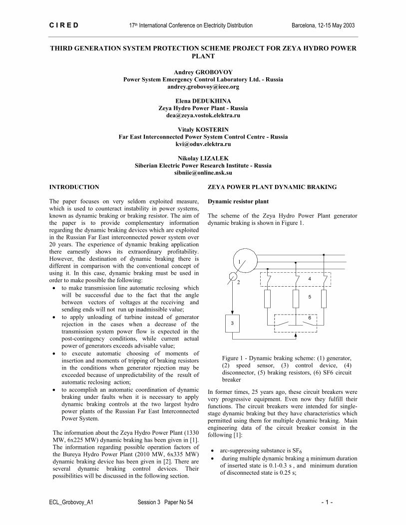
ZEYA POWER PLANT DYNAMIC BRAKING Dynamic resistor plant The scheme of the Zeya Hydro Power Plant generator dynamic braking is shown in Figure 1.
In former times, 25 years ago, these circuit breakers were very progressive equipment. Even now they fulfill their functions. The circuit breakers were intended for single-stage dynamic braking but they have characteristics which permitted using them for multiple dynamic braking. Main engineering data of the circuit breaker consist in the following [1]:
• arc-suppressing substance is SF6 • during multiple dynamic braking a minimum duration
of inserted state is 0.1-0.3 s , and minimum duration of disconnected state is 0.25 s;
Figure 1 - Dynamic braking scheme: (1) generator, (2) speed sensor, (3) control device, (4) disconnector, (5) braking resistors, (6) SF6 circuit breaker
1
2 4
5
63

CC II RR EE DD 17th International Conference on Electricity Distribution Barcelona, 12-15 May 2003
ECL_Grobovoy_A1 Session 3 Paper No 54 - 2 -
• nominal voltage of breaker is 15.75 kV; • nominal current of breaker is 7 kA; • quantity of the consecutive commutations is limited
by the pressure of air in the pipe of the drive. These events occur no more than 3 times.
One of six circuit breakers of the Zeya Hydro Power Plant generator dynamic braking is shown in Figure 2.
An important part of dynamic braking controls is the resistor plant. The engineering data of the first generation of resistor plant of this power station has been given in [1]. Now, after the recent reconstruction, each 54-MW resistor plant of every generator consists of three 18-MW resistors (one resistor per phase). Each of the resistors contains five parallel columns with two resistor elements in each column. In addition three columns (they have white cover in the figure) may be exploited in order to increase the dynamic braking power. The resistor element is a cylinder, 1 m in height and 0.2 m in diameter approximately. The braking resistor of the Zeya Hydro Power Plant generator dynamic braking is shown in Figure 3.
The braking resistor is intended for insertion duration of no more than 3 seconds. After that it demands preventive measures to be taken. Usually, the duration of insertion during multiple dynamic braking very seldom exceeds 1 second.
Control devices Being, at the present time, the largest hydro power plant of the Russian Far East Interconnected Power System, the Zeya Hydro Power Plant is an overwhelmingly important object for the power system emergency control structure. Having dynamic braking as one of the measures of system protection scheme (SPS), this power station is constantly attracting the attention of engineers. From the beginning of utilizing, started about twenty five years ago, the Zeya Hydro Power Plant’s SPS was behavior-assumption type, which uses “pre-fault calculation” to determine the needed control actions. The functions consisted in generator rejection, remote load shedding, and dynamic braking. The dynamic braking has been performed as “occurring once” using relay scheme as well as other controls. There were provided three different durations of dynamic braking. Each of them was selected depending on the strength of pre-fault conditions and fault intensity. Imperfection of such approach to selection of control action is well known. Therefore, subsequently, about 1987, the control law has been modified and the dynamic braking became "multiple". It became possible because of application of an electronic control device which used the local information about parameters of generator transient. Next, in 1991, the electronic control device has been replaced by a microprocessor controller, which also used the local information of transient of the generator during the first braking resistors energizing in order to determine the necessity and amount of generators rejecting. In addition the teleautomatic SPS "pre-fault calculation" type was put into operation. New SPS has replaced the relay-based control system. The dynamic braking control law has been described in [1] and [4]. It is the following:
)( δω ⋅⋅+= mksignU (1) Here, U is the control function; ω and δ are the rotor speed and the integral of the function )(tω respectively; m is a scale coefficient; k is a coefficient defined as:
1, if αδω ≤∩>∩< Jsignsign 0)(0)( k= (2) 0, if ( ) 0 ( ) 0sign sign Jω δ α≥ ∪ ≤ ∪ > Here, α is a setting value determined at the stage of the control device tuning, J is a parameter calculated by a special electronic scheme. The algorithm can be described as follows:
dtdω
, if )()0()0( 2
2J
dtd
dtd
dtd
>∩≥∩>ωωω
=J (3)
τt
eJm−⋅ , if
)0()0( 2
2<∪<
dtd
dtd ωω

CC II RR EE DD 17th International Conference on Electricity Distribution Barcelona, 12-15 May 2003
ECL_Grobovoy_A1 Session 3 Paper No 54 - 3 -
Here, dtdJmω
= is calculated at the moment when
(4)
The control law (1) - (4) allows taking into account the specific features of the dynamic braking controls' circuit breaker and the transmission system performance under disturbance. Figures 4 and 5 illustrate the principle of the controls.
The control device which implements the above control law and logic of selecting coefficient k was put into operation in 1987. The control device is shown in Figure 6. At the present time the device is still used as a stand-by one. The electronic control device was replaced by the microprocessor controller in 1991. The controller of dynamic braking is shown in the same figure. In addition to the algorithm of the above control device, it is executing extra functions of generator rejection. The generator rejection occurs in the first cycle of the dynamic braking when resistors are inserted already. Here is the main condition for generator rejection [1]:
0>dtdω (5)
The condition (5) is checked every time when a generator is rejected. Such way of step-by-step generator rejections is admissible only under applied dynamic braking that permits avoiding superfluous generator rejection and remote load shedding.
In addition, the "pre-fault calculation" type centralized teleautomatic SPS has been put into operation. The new SPS has replaced the relay-based control system. PROJECT OF THE THIRD GENEATION SPS Now it is evident that a modernization of the Zeya Hydro Power Plant's SPS is needed. The existing controls must be replaced by new SPS which can be described as the behavior-prediction SPS of “post-fault calculation” type. The prospective third generation SPS may have very multifarious and unusual characteristics. It is caused by new approaches to organization of emergency control system of the Russian Far East Interconnected Power System. The main decisions of the project that have been done lately will be discussed in this section.
)()0()0( 2
2
Jdtd
dtd
dtd
>∩>∩=ωωω
Figure 4 – Structure of control device: control (1), and monitoring (2) modules
Special sensor Calculator Control module
"OR "
Monitoring duration of cooling Monitoring numbers of insertion Monitoring duration of functioning
0.2 sec delay
Signal from speed sensor
Breaker’s auxiliary contact
insert
cut off
Triggering
Triggering
1
2
Monitoring resource of insertion
Figure 5 - а ) mechanism of determination of insertion moments; b)
mechanism of selecting coefficient k
δ - integral of speed , ω - speed , U – control function , J – subsidiary parameter
U
Moment of meeting the
condition: ω <0 Moment of meeting thecondition: ( ω +kδ)<0
ω δ
t
Moment of modification of k
Settingd ω dt J
d ω dt
t
а)
b)

CC II RR EE DD 17th International Conference on Electricity Distribution Barcelona, 12-15 May 2003
ECL_Grobovoy_A1 Session 3 Paper No 54 - 4 -
Transmission system model There are two reasons for starting the modernization of the Zeya Hydro Power Plant's SPS. The first of them consists in an obsolescence of the controllers' elements and the control center’s equipment. The second reason is the building of the Bureya Hydro Power Plant (2010 MW, 6x335 MW) that will be located not far from the Zeya Hydro Power Plant. The energy of these power stations will be transferred to consumers through the same transmission lines. In case of beginnings of a fault on the line, both power plants' SPS must be used to counteract instability of the transmission system. The Bureya Hydro Power Plant will be equipped by similar dynamic braking. Thus, a task of coordination of two SPS appears. The problem has been discussed in [3] and [4]. Some new approaches to organization of the emergency control system consist in the following. The scheme of transmission system which will come into being on completion of constructing the Bureya Power Plant may be very approximately presented as is shown in Figure 7.
Here, the generators G1 and G2 are models of the Zeya Hydro Power Plant, and generators G3 and G4 are ones of the Bureya Hydro Power Plant. The total length of the 500 kV transmission lines W1, W2 and W3 is about 1000 km. These transmission lines are shunted by the 220 kV ones labeled W4, W5, W6. The direction of energy transfer is from the generators G1-G4 to G5 that is equivalent of the receiving part of the interconnected power system. The most loaded transmission line is W3. Taking into account that the total power of G1-G4 is approximately equal to the power of G5, one can image the difficulties of emergency control in the power system. Fuzzy set theory exploitation Exactly therefore a new conception of emergency control has been suggested for the Russian Far East Interconnected Power System [1-4]. One of the suggestions, within the
framework of the concept, consists in using Fuzzy set theory in order to coordinate dynamic braking at the Zeya and Bureya Hydro Power Plants. Using the well known system MATLAB/Simulink, a comparison of several control laws has been made. Four control laws have been examined: two of them have been made on the basis of classic theory of automatic regulation, the other two - on the basis of Fuzzy set theory. The results of the investigation are shown in Figure 8. Using the system (1) - (4) and the sigmoid membership
functions, one can write the rules connecting input and output variables in accordance with the Mamdani system:
Figure 7 - Scheme of the transmission system: G1 – G5 - generators; T1 - T4 - transformers; T5 - T8 - autotransformers; W1 - W7 – transmission lines; L1 - L7 - loads; PN – nominal (P – current) generator capacity
PN=900 MW;P=700 МW;
PN=1340 МW;P=900 МW;
G1 T3G5
G3PN=7000 МW;P=4800 МW;
PN=450 МW;P=400 МW; PN=670 МW;
P=250 МW;
G2
G4
T1
T2T5 T6 T7 T8
T4
L1
L2 L3 L4 L5
L6
L7
W1 W2 W3 W7
W4 W5 W6

CC II RR EE DD 17th International Conference on Electricity Distribution Barcelona, 12-15 May 2003
ECL_Grobovoy_A1 Session 3 Paper No 54 - 5 -
zerothenKzeroandJpositiveif === ,,δ
bigthenKsmallandJpositiveif === ,,δ averthenKaverandJpositiveif === ,,δ smallthenKbigandJpositiveif === ,,δ
zerothenKnegativeif == ,δ In the exploration, another approach to selection of input variables and membership functions has been made. The Sugeno's system and membership functions, such as Z and S-function, were used. In this case, if J will be input, and K will be output variable, then one can write:
1, == thenKlowifJ 0, == KthenhighifJ
Figure 8 illustrates the results of dynamics simulation under different control laws. One can see a slight difference between the Sugeno algorithm, Mamdani system and existing control laws. However, it is needed to mark a slight difference that is observed under very strong conditions (the margin of stability limit is 5%). If this value is 15% or 20%, one can see a large difference, but these cases have not been shown in the paper. It is important to say that the calculating experiments have been executed in the conditions when generator rejection and remote load shedding have been applied simultaneously with dynamic braking. If a minimum of remote load shedding will serve as the criterion of optimality, in the majority of the considered cases with different stability margins, the law obtained with the use of the Mamdani system is better. Nevertheless, in any cases, the main goal of the emergency control has been achieved - the Zeya and Bureya Power Plants' dynamic braking coordination takes place. Main thesis of the project The discussion regarding the necessary type of the Bureya Power Plant's dynamic braking is still in progress. There are two suggestions concerning the type of circuit breaker of dynamic braking. It may be thyristor or mechanical breaker. In any case, fuzzy set theory permits choosing of duration of dynamic braking. This is especially true for the Zeya Hydro Power Plant's dynamic braking because of mechanical type of circuit breakers. Therefore, one of the main theses of the controls modernization project at the Zeya Hydro Power Plant is the suggestion to exploit fuzzy set theory. Taking into account the actual state of the control equipment, the suggestion to replace the existing dynamic braking controller by six controllers (one per each generator) has been made. Thus, the control system must be made as a three-level structure. The first level represents the control devices of dynamic braking. The second level represents a computation device for choosing control actions such as generation rejection and remote load shedding. The third level represents high-performance computers which are capable to implement a technology of neural networks in order to form the control action for long-term hydro turbine unloading. Figure 9 illustrates one of possible SPS’s for the Zeya Hydro Power Plant [3].
CONCLUSION A three-level structure of this SPS permits part-continuous method of modernization of the existing emergency control system of the Zeya Hydro Power Plant. The first phase of work is already started. It consists in replacement of the existing obsolete SPS by controllers of Compact PCI standard. The second phase will deal with PLC’s of the lower level intended for dynamic braking. At last, the third stage will deal with the equipment intended for information transfer from the regional control centre in order to accomplish the conception of power system emergency control, discussed in the following references. REFERENCES [1] A. A. Grobovoy, “Russian Far East Interconnected
Power System Emergency Stability Control,” Proceedings 2001 IEEE Summer Power Meeting, pp. 824-829.
[2] A. A. Grobovoy and N. N. Lizalek, “Multiple dynamic brake and power system emergency control”, Proceedings POWERCON’98, IEEE International Conference on Power System Technology, vol.2, pp. 1351-1355.
[3] А. A. Grobovoy, N. N. Lizalek, V. P. Patsev, V. K. Sukhoparov, S. P. Tishchenko and A. V. Khorokhov “Power Systems Centralized and Decentralized Emergency Stability Control”, Proceeding. CIGRE International Conference on Power Systems, ICPS’2001, pp. 458-463.
[4] A. A. Grobovoy, V. I. Kosterin, N. N. Lizalek, and Y.A. Vorobyov, “Impact of Perspective Technologies upon Control Structure of the Russian Far East Interconnected Power System”, Proceedings ECNEA’2002, pp. 409-420.
[5] A. Grobovoy, E. Dedukhina, N. Lizalek, V. Kosterin, V. Patsev, O. Shepilov, Y. Vorobyov, “Several approaches to control action choosing in the Russian Far East interconnected power system”, presented to CIGRE Symposium, Shanghai, 2003.
Datatransferring
Communicationserver
Cluster
Redundancy ring100 Mbit/s
CANbus
PLC
CPCITelemonitoring,
telemetering,contingency
detecting, andcontrol orderstransferring
Firewire
Figure 9 – Configuration of SPS: CPCI is Compact PCI and PLC is programmable logic controllers