thin solid films - ntu · 5.1. hard coatings ... x. zhang / thin solid films 520 (2012) 2375–2389...
TRANSCRIPT

Thin Solid Films 520 (2012) 2375–2389
Contents lists available at SciVerse ScienceDirect
Thin Solid Films
j ourna l homepage: www.e lsev ie r .com/ locate / ts f
Critical review
Toughness evaluation of hard coatings and thin films
Sam Zhang ⁎, Xiaomin ZhangSchool of Mechanical and Aerospace Engineering, Nanyang Technological University, 50 Nanyang Avenue, Singapore 639798, Singapore
⁎ Corresponding author. Tel.: +65 6790 4400; fax: +E-mail address: [email protected] (S. Zhang).
0040-6090/$ – see front matter © 2011 Elsevier B.V. Alldoi:10.1016/j.tsf.2011.09.036
a b s t r a c t
a r t i c l e i n f oAvailable online 24 September 2011
Keywords:Thin filmsCoatingsFracture toughness
Enormous progress has been achieved over the past decade in evaluating the toughness of hard coatings andthin films. This paper reviews methodologies developed based on indentation, bending, and microtensiletesting. In addition, we discuss a recent development in fracture toughness measurement which involvesthe application of macrotension to a substrate in order to induce microtension in a patterned thin film.
65 6791 1859.
rights reserved.
© 2011 Elsevier B.V. All rights reserved.
Contents
1. Introduction . . . . . . . . . . . . . . . . . . . . . . . . . . . . . . . . . . . . . . . . . . . . . . . . . . . . . . . . . . . . . . 23752. Qualitative assessment . . . . . . . . . . . . . . . . . . . . . . . . . . . . . . . . . . . . . . . . . . . . . . . . . . . . . . . . . 2376
2.1. Indentation plasticity . . . . . . . . . . . . . . . . . . . . . . . . . . . . . . . . . . . . . . . . . . . . . . . . . . . . . . 23762.2. Scratch toughness . . . . . . . . . . . . . . . . . . . . . . . . . . . . . . . . . . . . . . . . . . . . . . . . . . . . . . . . 2376
3. Quantitative toughness characterization for coatings . . . . . . . . . . . . . . . . . . . . . . . . . . . . . . . . . . . . . . . . . . . 23773.1. Toughness evaluation from radial cracks . . . . . . . . . . . . . . . . . . . . . . . . . . . . . . . . . . . . . . . . . . . . . 23773.2. Toughness evaluation from circumferential cracking and spallation . . . . . . . . . . . . . . . . . . . . . . . . . . . . . . . . . 23793.3. Toughness evaluation from channel cracking . . . . . . . . . . . . . . . . . . . . . . . . . . . . . . . . . . . . . . . . . . . 2382
4. Microtensile testing of fracture toughness for standalone thin films . . . . . . . . . . . . . . . . . . . . . . . . . . . . . . . . . . . . 23844.1. Inchworm actuation . . . . . . . . . . . . . . . . . . . . . . . . . . . . . . . . . . . . . . . . . . . . . . . . . . . . . . . 23854.2. Membrane deflection . . . . . . . . . . . . . . . . . . . . . . . . . . . . . . . . . . . . . . . . . . . . . . . . . . . . . . 23854.3. Tension by residual stress . . . . . . . . . . . . . . . . . . . . . . . . . . . . . . . . . . . . . . . . . . . . . . . . . . . . 23864.4. Bulging of films . . . . . . . . . . . . . . . . . . . . . . . . . . . . . . . . . . . . . . . . . . . . . . . . . . . . . . . . . 23874.5. Macrotension of substrate . . . . . . . . . . . . . . . . . . . . . . . . . . . . . . . . . . . . . . . . . . . . . . . . . . . . 2387
5. Summary . . . . . . . . . . . . . . . . . . . . . . . . . . . . . . . . . . . . . . . . . . . . . . . . . . . . . . . . . . . . . . . 23885.1. Hard coatings . . . . . . . . . . . . . . . . . . . . . . . . . . . . . . . . . . . . . . . . . . . . . . . . . . . . . . . . . . 23885.2. Thin films . . . . . . . . . . . . . . . . . . . . . . . . . . . . . . . . . . . . . . . . . . . . . . . . . . . . . . . . . . . . 2388
Acknowledgments. . . . . . . . . . . . . . . . . . . . . . . . . . . . . . . . . . . . . . . . . . . . . . . . . . . . . . . . . . . . . . 2388References . . . . . . . . . . . . . . . . . . . . . . . . . . . . . . . . . . . . . . . . . . . . . . . . . . . . . . . . . . . . . . . . . 2388
1. Introduction
Toughness is one of the important mechanical properties of a ma-terial. The term toughness refers to the ability of a material to absorbenergy during deformation up to fracture [1–2], usually measured interms of fracture toughness. In classical mechanics, fracture toughnessrefers to the stress resistance of a material to fracture in the presenceof a flaw, i.e. the highest stress intensity that the material can
withstand without fracture [3]. It is measured as the maximum stressintensity factor under plane strain condition [4–5]. To meet the “planestrain” condition, the specimen dimensions, t,a and (W−a), shouldrespectively satisfy the following inequality:
t; a; W−að Þ≥ 2:5KIC
σy
!2
; ð1Þ
where t andW are specimen thickness and width respectively, a is theflaw size, σy is the yield stress, and KIC is the critical stress intensitythat a material can withstand without fracture. In essence, Eq. (1) re-quires that the sample thickness should be large enough, while the
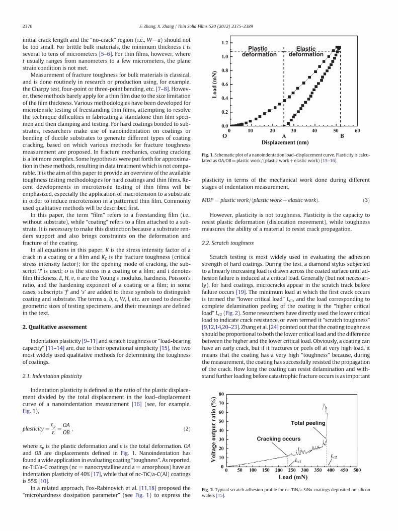
Plastic Elastic deformation deformation
Fig. 1. Schematic plot of a nanoindentation load–displacement curve. Plasticity is calcu-lated as OA/OB=plastic work/(plastic work+elastic work) [15–16].
Cracking occurs
Total peeling
Fig. 2. Typical scratch adhesion profile for nc-TiN/a-SiNx coatings deposited on siliconwafers [15].
2376 S. Zhang, X. Zhang / Thin Solid Films 520 (2012) 2375–2389
initial crack length and the “no-crack” region (i.e., W−a) should notbe too small. For brittle bulk materials, the minimum thickness t isseveral to tens of micrometers [5–6]. For thin films, however, wheret usually ranges from nanometers to a few micrometers, the planestrain condition is not met.
Measurement of fracture toughness for bulk materials is classical,and is done routinely in research or production using, for example,the Charpy test, four-point or three-point bending, etc. [7–8]. Howev-er, thesemethods barely apply for a thin film due to the size limitationof the film thickness. Various methodologies have been developed formicrotensile testing of freestanding thin films, attempting to resolvethe technique difficulties in fabricating a standalone thin film speci-men and then clamping and testing. For hard coatings bonded to sub-strates, researchers make use of nanoindentation on coatings orbending of ductile substrates to generate different types of coatingcracking, based on which various methods for fracture toughnessmeasurement are proposed. In fracture mechanics, coating crackingis a lotmore complex. Some hypotheseswere put forth for approxima-tion in thesemethods, resulting in data treatmentwhich is not compa-rable. It is the aim of this paper to provide an overview of the availabletoughness testing methodologies for hard coatings and thin films. Re-cent developments in microtensile testing of thin films will beemphasized, especially the application of macrotension to a substratein order to induce microtension in a patterned thin film. Commonlyused qualitative methods will be described first.
In this paper, the term “film” refers to a freestanding film (i.e.,without substrate), while “coating” refers to a film attached to a sub-strate. It is necessary to make this distinction because a substrate ren-ders support and also brings constraints on the deformation andfracture of the coating.
In all equations in this paper, K is the stress intensity factor of acrack in a coating or a film and KC is the fracture toughness (criticalstress intensity factor); for the opening mode of cracking, the sub-script ‘I’ is used; σ is the stress in a coating or a film; and t denotesfilm thickness. E, H, υ, n are the Young's modulus, hardness, Poisson'sratio, and the hardening exponent of a coating or a film; in somecases, subscripts ‘f’ and ‘s’ are added to these symbols to distinguishcoating and substrate. The terms a, b, c, W, l, etc. are used to describegeometric sizes of testing specimens, and their meanings are definedin the text.
2. Qualitative assessment
Indentation plasticity [9–11] and scratch toughness or “load-bearingcapacity” [11–14] are, due to their operational simplicity [15], the twomost widely used qualitative methods for determining the toughnessof coatings.
2.1. Indentation plasticity
Indentation plasticity is defined as the ratio of the plastic displace-ment divided by the total displacement in the load–displacementcurve of a nanoindentation measurement [16] (see, for example,Fig. 1),
plasticity ¼ εpε
¼ OAOB
; ð2Þ
where εp is the plastic deformation and ε is the total deformation. OAand OB are displacements defined in Fig. 1. Nanoindentation hasfound awide application in evaluating coating “toughness”. As reported,nc-TiC/a-C coatings (nc=nanocrystalline and a= amorphous) have anindentation plasticity of 40% [17], while that of nc-TiC/a-C(Al) coatingsis 55% [10].
In a related approach, Fox-Rabinovich et al. [11,18] proposed the“microhardness dissipation parameter” (see Fig. 1) to express the
plasticity in terms of the mechanical work done during differentstages of indentation measurement,
MDP ¼ plastic work= plastic workþ elastic workð Þ: ð3Þ
However, plasticity is not toughness. Plasticity is the capacity toresist plastic deformation (dislocation movement), while toughnessmeasures the ability of a material to resist crack propagation.
2.2. Scratch toughness
Scratch testing is most widely used in evaluating the adhesionstrength of hard coatings. During the test, a diamond stylus subjectedto a linearly increasing load is drawn across the coated surface until ad-hesion failure is induced at a critical load. Generally (but not necessari-ly), for hard coatings, microcracks appear in the scratch track beforefailure occurs [19]. The minimum load at which the first crack occursis termed the “lower critical load” Lc1, and the load corresponding tocomplete delamination peeling of the coating is the “higher criticalload” Lc2 (Fig. 2). Some researchers have directly used the lower criticalload to indicate crack resistance, or even termed it “scratch toughness”[9,12,14,20–23]. Zhang et al. [24] pointed out that the coating toughnessshould be proportional to both the lower critical load and the differencebetween the higher and the lower critical load. Obviously, a coating canhave an early crack, but if it fractures or peels off at very high load, itmeans that the coating has a very high “toughness” because, duringthemeasurement, the coating has successfully resisted the propagationof the crack. How long the coating can resist delamination and with-stand further loading before catastrophic fracture occurs is as important
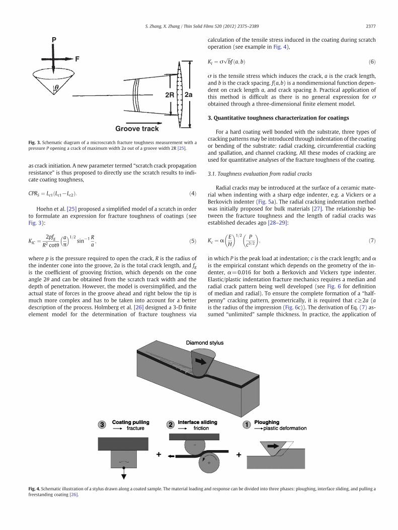
Groove track
P
F
2R 2a
Fig. 3. Schematic diagram of a microscratch fracture toughness measurement with apressure P opening a crack of maximum width 2a out of a groove width 2R [25].
2377S. Zhang, X. Zhang / Thin Solid Films 520 (2012) 2375–2389
as crack initiation. A new parameter termed “scratch crack propagationresistance” is thus proposed to directly use the scratch results to indi-cate coating toughness,
CPRS ¼ Lc1 Lc1−Lc2ð Þ: ð4Þ
Hoehn et al. [25] proposed a simplified model of a scratch in orderto formulate an expression for fracture toughness of coatings (seeFig. 3):
KIC ¼ 2pfgR2 cotθ
aπ
� �1=2sin−1 R
a; ð5Þ
where p is the pressure required to open the crack, R is the radius ofthe indenter cone into the groove, 2a is the total crack length, and fgis the coefficient of grooving friction, which depends on the coneangle 2θ and can be obtained from the scratch track width and thedepth of penetration. However, the model is oversimplified, and theactual state of forces in the groove ahead and right below the tip ismuch more complex and has to be taken into account for a betterdescription of the process. Holmberg et al. [26] designed a 3-D finiteelement model for the determination of fracture toughness via
Fig. 4. Schematic illustration of a stylus drawn along a coated sample. The material loading afreestanding coating [26].
calculation of the tensile stress induced in the coating during scratchoperation (see example in Fig. 4),
KI ¼ σffiffiffib
pf a; bð Þ ð6Þ
σ is the tensile stress which induces the crack, a is the crack length,and b is the crack spacing. f(a,b) is a nondimensional function depen-dent on crack length a, and crack spacing b. Practical application ofthis method is difficult as there is no general expression for σobtained through a three-dimensional finite element model.
3. Quantitative toughness characterization for coatings
For a hard coating well bonded with the substrate, three types ofcracking patternsmay be introduced through indentation of the coatingor bending of the substrate: radial cracking, circumferential crackingand spallation, and channel cracking. All these modes of cracking areused for quantitative analyses of the fracture toughness of the coating.
3.1. Toughness evaluation from radial cracks
Radial cracks may be introduced at the surface of a ceramic mate-rial when indenting with a sharp edge indenter, e.g. a Vickers or aBerkovich indenter (Fig. 5a). The radial cracking indentation methodwas initially proposed for bulk materials [27]. The relationship be-tween the fracture toughness and the length of radial cracks wasestablished decades ago [28–29]:
Kc ¼ αEH
� �1=2 Pc3=2
� �; ð7Þ
in which P is the peak load at indentation; c is the crack length; and αis the empirical constant which depends on the geometry of the in-denter, α=0.016 for both a Berkovich and Vickers type indenter.Elastic/plastic indentation fracture mechanics requires a median andradial crack pattern being well developed (see Fig. 6 for definitionof median and radial). To ensure the complete formation of a “half-penny” cracking pattern, geometrically, it is required that c≥2a (ais the radius of the impression (Fig. 6c)). The derivation of Eq. (7) as-sumed “unlimited” sample thickness. In practice, the application of
nd response can be divided into three phases: ploughing, interface sliding, and pulling a

Radial
a
Median
Half penny
b
c
Fig. 6. Crack patterns in a brittle material upon Vickers indentation: (a) a radial crack;(b) a median crack; (c) half-penny cracking (a combination of a radial crack and a me-dian crack) [41].
Fig. 5. (a) Schematic illustration of radial cracking upon Vickers indentation, and(b) ultra-low load nanoindentation radial cracks [27].
2378 S. Zhang, X. Zhang / Thin Solid Films 520 (2012) 2375–2389
Eq. (7) requires that the depth d of the half-penny crack beneath thesurface be less than one-tenth of the thickness of the sample [30].
An ultralow load is applied during nanoindentation of coatings[27] (Fig. 5b). For a coating with residual stress σr, the following rela-tionship is commonly used [31–32]
KIC ¼ αEH
� �1=2 Pc3=2
� �þ Zσrc
1=2; ð8Þ
where Z is the crack shape factor given by [32]
Z ¼ 1:12ffiffiffiπ
p d=c3π8
� �þ π8
� �d=cð Þ2 : ð9Þ
Z=1.26 for an idealized half-penny, i.e. the depth d of the crack isequal to the crack length c, making the half-penny an ideal semicircle.
To meet the geometrical requirements of Eqs. (7) or (8), the in-dentation depth (smaller than the depth d of the crack induced)should be much less than 10% of the coating thickness. However, aload threshold exists for the occurrence of the radial crack during in-dentation. For most ceramic materials, the threshold load of a Vickersor Berkovich indentation is 250 mN or more, and the correspondingimpression produced is several micrometers in depth [27,33]. Asharper angle indenter greatly reduces the threshold load for radialcracks. For example, indenting with a cube-corner indenter reduces
the load threshold by at least an order of magnitude compared withthat with a Vickers indenter [27]. Yet even here, the indentationdepth is still a few hundred nanometers for many brittle materialsin order to induce a radial crack [34]. Therefore, for coatings, to intro-duce well-developed radial cracks, the depth limitation of nanoinden-tation to exclude substrate effects is usually very difficult to meet.
Unlike standardized tests with a single well-defined crack in awell-defined loading configuration (like uniaxial tensile testing)[35], indentation induces a complex crack network and residual dam-age around the impression. This makes mechanical analysis extreme-ly difficult [29,36]. The “expanding cavity” model was adopted todepict the damage zone of an indentation [28,37], but its reliabilityis questionable [38–39]: experiments on bulk ceramic materialsrevealed that the details of indentation cracking are extremely mate-rial dependent. That is, the crack patterns are often not the idealizedhalf-penny shape as assumed in the model [40–41]. In bulk ceramic

First ring-like through-thickness crack formation
Delamination and buckling
a
2379S. Zhang, X. Zhang / Thin Solid Films 520 (2012) 2375–2389
materials, the actual crack pattern is obtained through observing thecross-section of the median/radial crack (Fig. 6c) [41–42], but it is al-most impossible to do the same on coatings. Therefore, it is very dif-ficult to judge the reliability of Eqs. (7) and (8) for coatings.
A substrate indentationmethodwas proposed to tackle the problemof substrate influence [43]: indentation is conducted on the uncoatedside of the substrate surface such that the radial crack in the substratepropagates into the coating. In this way, a single through-thicknesscrack is induced in the coating (Fig. 7a). The tougher the coating, theshorter the crack in the coating (Fig. 7b). Based on the energy balanceprinciple, the following equation is obtained
Af Gf þ AsGs ¼ Asf As þ AssGs: ð10Þ
Gf and Gs are the strain energy release rates for coating and substrate, Afand As are true cracked film and substrate areas. Asf, and Ass are crackedareas when coating properties are identical to those of the substrate.Through comparing the crack lengths of coated and uncoated sides, anexpression is obtained for the toughness of the coating
Kf ¼ K2s 1þ λ
ϕb−að Þt
ffiffiffiffiffiffiffiffiffiffiffiffiffiffiffiffiffiffiffiffiffiffiffiffiEfEs
1−υ2s
� �1−υ2
f
� �vuut
264
3752
þ 2ψcσr
ffiffit
pffiffiffiffiffiffiffiffiffiffiffiffiffiffiffiffiffiffiffiffiffiffiffiffiEfEs
1−υ2s
� �1−υ2
f
� �vuut
264
37528><
>:9>=>;
1=2
;
ð11Þ
where the subscript f′ refers to the film and s′ to the substrate; Ks is thefracture toughness of the substrate; a and b are crack lengths as shownin Fig. 7a; the dimensionless factors λ and ψc are 0.45 and 0.95 respec-tively, obtained from finite element model (FEM) calculations; and ϕis a geometry term obtained from FEM.
Wedge model
Half-infinite plate model
Crack growth
= 10 No coating6
-10
-20
-30
-40
-50
-60
-70
-80
Indenter
0
b
a
20 40 60 80 100-20-80 -60 -40-100
Fig. 7. (a) Schematic of indentation geometry; (b) crack growth front for different filmfracture toughnesses Kc [43].
3.2. Toughness evaluation from circumferential cracking and spallation
Circumferential cracking and spallation describe peeling of thecoating around the indentation (Fig. 8a). For a very brittle coating, itis generated upon nanoindentation. At spallation, a plateau forms inthe load–displacement curve (see Fig. 8b) [34,44–47], which can beused to produce a quantitative estimate of the coating fracture tough-ness. Li et al. (Fig. 8a) [34] suggested that fracture proceeds as follows:(1) the first circumferential through-thickness crack forms around theindenter by high stress in the contact area; (2) delamination andbuckling occur around the contact area at the coating/substrate inter-face due to high lateral pressure; (3) a second circumferentialthrough-thickness crack forms, and spallation is generated by high
Second ring-like through-thickness crack formation
Lateral cracking during unloading
Partial spalling formation
b
Fig. 8. (a) Schematic illustration of the three stages in nanoindentation fracture for thincoatings; (b) schematic of a load–displacement curve, showing a step during the load-ing cycle and associated energy release [34].

Fig. 10. Schematic diagram representing the fracture energy U of a coating at the pla-teau in a nanoindentation load–displacement curve: the segment (GB) represents apartial loading curve of the Si substrate; the dotted area (ABEF) represents the totalwork under the step (done by the indenter); the gray area 1 (ABH) represents the en-ergy released on circumferential cracking and spallation, while the area 2 (BEF) repre-sents the energy of Si deformation [46].
2380 S. Zhang, X. Zhang / Thin Solid Films 520 (2012) 2375–2389
bending stresses at the edges of the buckled thin coating. The thirdstage, circumferential through-thickness cracking and spallation ofthe coating, causes a sudden excursion of the indenter in displace-ment, which induces a step in the load–displacement curve (Fig. 8b).Given area ABC in Fig. 8b representing the energy U dissipated uponcoating cracking, the fracture toughness is obtained as
KC ¼ EU1−ν2� �
A
" #1=2; ð12Þ
in which A=2πCRt is the crack area, 2πCR is the crack length in thecoating plane, CR is the radius of circumferential through-thicknesscrack formed around the indenter, and t is the coating thickness. Eand ν are Young's modulus and Poisson's ratio of the coating, respec-tively.In Eq. (12), the coating fracture energy U is the irreversiblework Wirr of the indenter during the excursion from A to B.
However, extraction of the irreversible work Wirr became the focalpoint of much debate. denToonder et al. [44] suggested the lower andupper boundaries of the Wirr as shown in Fig. 9: the areas of OAB andABFR, which correspond to the cases of full elastic deformation and fullplastic deformation of the coated system, respectively. Chen and Bull[47] considered the area ABQE as representing the irreversible workWirr, with AE and BQ being the unloading curves at excursion startpoint and end point. Further, they provided a method to obtain theunloading curve AE through the linear relationship between the ratioof displacement δf/δ1 and that of hardness over Young'smodulus (Hs/Es):
δfδ1
¼ 1−λHs
Es; ð13Þ
where Hs and Es are the hardness and Young's modulus of the substrate.λ=4.5 for a Berkovich indenter. δf, and δ1 are the residual displacementand full displacement of indentation as shown in Fig. 9. Expression (13)is developed for bulk materials without fracture [48]. It approximatelyapplies to coated systems inwhich the substrate dominates the deforma-tion in deep indentations. In this way, the lower boundary ABE and theupper boundary ABFE of the irreversible work Wirr are obtained.
Michel et al. [46] realized that apart from the fracture energy U ofthe coating, the energy consumed in substrate deformation is also in-cluded in thework done by the indenter. He proposedABH in Fig. 10 asthe fracture energy U of the coating. In Fig. 10, ABEF represents thetotal work of the indenter during circumferential cracking and
Fig. 9. Schematic illustration of the boundaries of the irreversible work Wirr at the pla-teau in a nanoindentation load–displacement curve [47].
spallation of the coating, and segment GB represents a partial loadingcurve of the silicon substrate.
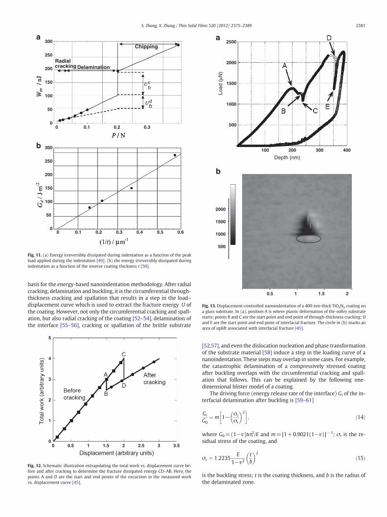
Malzbender et al. [44,49] studied the change of the irreversible en-ergyWirr versus load P through conducting a set of loading–unloadingcycles before and after the spallation of a coating. They found that thecurve of Wirr vs. P was divided into several segments of straight linesrepresenting different events during cracking: radial cracking, delam-ination, circumferential through-thickness cracking, and chipping(Fig. 11a). Apparently, the irreversible work Wirr was obtained fromthe energy difference Ufr
c just before and after the circumferentialthrough-thickness cracking. Further, they found that Wirr is coating-thickness dependent [50]: the thinner the coating is, the larger the ir-reversible energy dissipation Wirr. The authors claimed that it is dueto the fact that more substrate deformation is involved for a thinnercoating during indentation. Accordingly, the fracture energy U isobtained through extrapolating Wirr of the coating to infinite coatingthickness (Fig. 11b).
Chen and Bull [45,51] extracted the fracture energy U of a coatingfrom the curve of total work Wt versus displacement D (see exampleFig. 12). First, the initialWt vs. D curve is extrapolated from the crack-ing start point A to the cracking end point C. ThenWt vs. D curve aftercracking is extrapolated back to the cracking start point. Vertical Wt
differences AB and CD are thus obtained. AB represents the work dif-ference consumed in the elastic–plastic deformation of the coating/substrate system before and after the coating fracture, and CD is thetotal work done during the cracking. The difference between CD andAB is thus deemed the fracture energy U.
Displacement-controlled nanoindentation of thin ceramic coat-ings with a sharp indenter (cube corner tip with radius of 40 nmwhen new) was extensively investigated by Chen and Bull [45,51].Displacement-controlled indentation was supposed to be more sensi-tive to the coating cracking because the load drop at coating fracture isunambiguously related to the loss of the contact of the indenter withthe coating/substrate system. On the contrary, in addition to the indent-ermovement due to the loss of contact, there is an additionalmovementof the indenter due to the deformation of the coating/substrate systemat the fracture load. Fig. 13a shows a typical load–displacement curveof a displacement-controlled nanoindentation conducted on a 400 nmTiOxNy coating on a glass substrate, in which the load jump between Band C is associated with the radial through-thickness cracking of thecoating [45]. TheWt vs.Dmethodwas used to obtain the fracture energyU and the fracture toughness was obtained according to Eq. (12).
The fracture behavior of a thin hard coating in nanoindentation asdescribed by Li et al. (Fig. 8a) [34] and Malzbender et al. [49] is the
2500
2000
1500
1000
500
2000
1500
1000
500
0.5 1 1.5 2
100 200 300 400
Depth (nm)
Load
(µN
)
b
a
Fig. 13. Displacement-controlled nanoindentation of a 400-nm-thick TiOxNy coating ona glass substrate. In (a), position A is where plastic deformation of the softer substratestarts; points B and C are the start point and end point of through-thickness cracking; Dand E are the start point and end point of interfacial fracture. The circle in (b) marks anarea of uplift associated with interfacial fracture [45].
300
250
200
150
100
50
0
cracking Radial
Delamination
Chipping
300
250
200
150
100
50
00
0
0.1
0.1
0.2
0.2
0.3
0.3
0.4 0.5 0.6
b
a
Fig. 11. (a) Energy irreversibly dissipated during indentation as a function of the peakload applied during the indentation [49]; (b) the energy irreversibly dissipated duringindentation as a function of the inverse coating thickness t [50].
2381S. Zhang, X. Zhang / Thin Solid Films 520 (2012) 2375–2389
basis for the energy-based nanoindentation methodology. After radialcracking, delamination and buckling, it is the circumferential through-thickness cracking and spallation that results in a step in the load–displacement curve which is used to extract the fracture energy U ofthe coating. However, not only the circumferential cracking and spall-ation, but also radial cracking of the coating [52–54], delamination ofthe interface [55–56], cracking or spallation of the brittle substrate
0 0.5 1 1.5 2 2.5 3 3.5
5
4
3
2
1
0
Fig. 12. Schematic illustration extrapolating the total work vs. displacement curve be-fore and after cracking to determine the fracture dissipated energy CD–AB. Here, thepoints A and D are the start and end points of the excursion in the measured workvs. displacement curve [45].
[52,57], and even the dislocation nucleation and phase transformationof the substrate material [58] induce a step in the loading curve of ananoindentation. These stepsmay overlap in some cases. For example,the catastrophic delamination of a compressively stressed coatingafter buckling overlaps with the circumferential cracking and spall-ation that follows. This can be explained by the following one-dimensional blister model of a coating.
The driving force (energy release rate of the interface) Gi of the in-terfacial delamination after buckling is [59–61]
Gi
G0¼ m 1− σc
σr
� �2 ; ð14Þ
where G0=(1−υ)tσr2/E and m=[1+0.9021(1−υ)]−1; σr is the re-
sidual stress of the coating, and
σc ¼ 1:2235E
1−υ2
tb
� �2ð15Þ
is the buckling stress; t is the coating thickness, and b is the radius ofthe delaminated zone.
Advancing crack front
x
y t
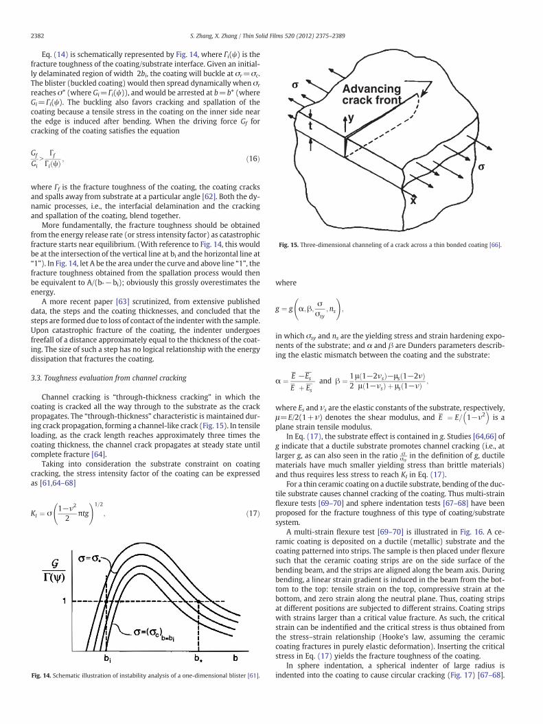
Fig. 15. Three-dimensional channeling of a crack across a thin bonded coating [66].
2382 S. Zhang, X. Zhang / Thin Solid Films 520 (2012) 2375–2389
Eq. (14) is schematically represented by Fig. 14, where Γi(ψ) is thefracture toughness of the coating/substrate interface. Given an initial-ly delaminated region of width 2bi, the coating will buckle at σr=σc.The blister (buckled coating) would then spread dynamically when σr
reaches σ* (where Gi=Γi(ψ)), and would be arrested at b=b* (whereGi=Γi(ψ). The buckling also favors cracking and spallation of thecoating because a tensile stress in the coating on the inner side nearthe edge is induced after bending. When the driving force Gf forcracking of the coating satisfies the equation
Gf
GiN
ΓfΓi ψð Þ ; ð16Þ
where Γf is the fracture toughness of the coating, the coating cracksand spalls away from substrate at a particular angle [62]. Both the dy-namic processes, i.e., the interfacial delamination and the crackingand spallation of the coating, blend together.
More fundamentally, the fracture toughness should be obtainedfrom the energy release rate (or stress intensity factor) as catastrophicfracture starts near equilibrium. (With reference to Fig. 14, this wouldbe at the intersection of the vertical line at bi and the horizontal line at“1”). In Fig. 14, let A be the area under the curve and above line “1”, thefracture toughness obtained from the spallation process would thenbe equivalent to A/(b*−bi); obviously this grossly overestimates theenergy.
A more recent paper [63] scrutinized, from extensive publisheddata, the steps and the coating thicknesses, and concluded that thesteps are formed due to loss of contact of the indenterwith the sample.Upon catastrophic fracture of the coating, the indenter undergoesfreefall of a distance approximately equal to the thickness of the coat-ing. The size of such a step has no logical relationship with the energydissipation that fractures the coating.
3.3. Toughness evaluation from channel cracking
Channel cracking is “through-thickness cracking” in which thecoating is cracked all the way through to the substrate as the crackpropagates. The “through-thickness” characteristic is maintained dur-ing crack propagation, forming a channel-like crack (Fig. 15). In tensileloading, as the crack length reaches approximately three times thecoating thickness, the channel crack propagates at steady state untilcomplete fracture [64].
Taking into consideration the substrate constraint on coatingcracking, the stress intensity factor of the coating can be expressedas [61,64–68]
KI ¼ σ1−ν2
2πtg
!1=2
; ð17Þ
Fig. 14. Schematic illustration of instability analysis of a one-dimensional blister [61].
where
g ¼ g α;β;σσsy
;ns
!;
in which σsy and ns are the yielding stress and strain hardening expo-nents of the substrate; and α and β are Dunders parameters describ-ing the elastic mismatch between the coating and the substrate:
α ¼ E −EsE þ Es
and β ¼ 12μ 1−2νsð Þ−μs 1−2νð Þμ 1−νsð Þ þ μs 1−νð Þ ;
where Es and νs are the elastic constants of the substrate, respectively,μ=E/2(1+ν) denotes the shear modulus, and E ¼ E= 1−ν2
� �is a
plane strain tensile modulus.In Eq. (17), the substrate effect is contained in g. Studies [64,66] of
g indicate that a ductile substrate promotes channel cracking (i.e., atlarger g, as can also seen in the ratio σ
σsyin the definition of g, ductile
materials have much smaller yielding stress than brittle materials)and thus requires less stress to reach KI in Eq. (17).
For a thin ceramic coating on a ductile substrate, bending of the duc-tile substrate causes channel cracking of the coating. Thus multi-strainflexure tests [69–70] and sphere indentation tests [67–68] have beenproposed for the fracture toughness of this type of coating/substratesystem.
A multi-strain flexure test [69–70] is illustrated in Fig. 16. A ce-ramic coating is deposited on a ductile (metallic) substrate and thecoating patterned into strips. The sample is then placed under flexuresuch that the ceramic coating strips are on the side surface of thebending beam, and the strips are aligned along the beam axis. Duringbending, a linear strain gradient is induced in the beam from the bot-tom to the top: tensile strain on the top, compressive strain at thebottom, and zero strain along the neutral plane. Thus, coating stripsat different positions are subjected to different strains. Coating stripswith strains larger than a critical value fracture. As such, the criticalstrain can be indentified and the critical stress is thus obtained fromthe stress–strain relationship (Hooke's law, assuming the ceramiccoating fractures in purely elastic deformation). Inserting the criticalstress in Eq. (17) yields the fracture toughness of the coating.
In sphere indentation, a spherical indenter of large radius isindented into the coating to cause circular cracking (Fig. 17) [67–68].

Plastic zone
Radial crack
a
Fig. 16. A multistrain specimen and test configuration [70].
2383S. Zhang, X. Zhang / Thin Solid Films 520 (2012) 2375–2389
The strain of the coating under the indenter is axisymmetric and is afunction of the location (r), as given by Eq. (18) [21],
εrεsy
¼ m1 εsy� � r
D
� �þm2 εsy;ns
� � rD
� �3; ð18Þ
where εr is the strain in the radial direction; r andD are the radius of im-pression and sphere indenter diameter respectively; and εsy and ns are
Sphere
Substrate
Film
Impression
ar
Circumferentialcracks
Fig. 17. The sphere indentation test: circumferential cracks develop within the indent[67].
the yielding strain and hardening exponent of the ductile substrate.The terms m1 and m2 are defined as:
m1 εsy� �
¼ 1:45þ 0:14εsy
m2 εsy;ns
� �¼ 1466−118ns½ � þ −22:7þ 1:8ns½ � 1
εsy
!
þ 0:075−0:003ns½ � 1εsy
!2
:
Once the critical strain is identified, the critical stress is obtainedthrough Hooke's law, thus Eq. (17) yields the ceramic coating's frac-ture toughness. Expression (18) is suitable for most metallic sub-strates [67].
The parameter g in Eq. (17) describes the constraint of the sub-strate on the channel cracking of the coating. It is very complex forductile substrates [66], which hinders its application. In practice, it isdifficult to make coating strips on a metallic substrate by lithography.In the case of the sphere indentation test, accurately locating the firstcrack on the unloaded impression is a problem.
For thin hard coatings deposited on rigid (ceramic) substrates,nanoindentation with a sharp edge indenter can be used to generateradial channel cracks [19,57], as illustrated in Fig. 18. A hemisphericalplastic zone is generated under the contact at the beginning of inden-tation; with increasing load, the plastic zone expands further and itshemispherical shape changes upon impinging with the substrate.The radial cracks emanate from the sharp corners. With further load-ing, the plastic zone transforms to cylindrical and the radial cracks be-come channel cracks (Fig. 18b) [71–72].
According to the rigid substrate hypothesis, the indented volumeof the coating material is solely accommodated via deformation of
Film
Substrate
bPlastic zone
Channelcrack
Film
Substrate
Fig. 18. (a) Schematic cross-section of indentation-induced partial-penetration radialfracture in a mechanically-thick coating. When the coating is thick compared to theplastic zone, the plastic zone is spherical in shape and radial cracks are seen as surfacetraces. (b) Schematic cross-section of indentation-induced channel cracking in a me-chanically thin coating. Here, the plastic zone is cylindrically shaped due to the con-straint of the substrate and the channel cracks extend through the coating [71–72].

Fig. 19. SEM image of a coating fracture in tetrahedral amorphous carbon (ta-C). Thecoating thickness is 248 nm [71].
2384 S. Zhang, X. Zhang / Thin Solid Films 520 (2012) 2375–2389
the coating. This requires a substrate much harder and tougher thanthe coating [73]. Otherwise, the plastic zone may extend into the sub-strate [58] or, evenworse, cause extensive substrate deformation [74].Assuming there is no deformation in the substrate, the stress intensityfactor of indentation-driven channel cracking is derived as [61,75]
KI ¼ λV� Ef H2f
� �1=3tf
a2
c1=2: ð19Þ
The subscript f′ refers to “film” or coating properties and λ is ap-proximately 0.013 for the Vickers geometry and 0.016 for the cube-corner geometry. a is the radius of the indentation, and c is thecrack length. For a well-developed channel crack, Eq. (19) requiresthat the crack length is larger than three times of the film thicknessas shown in Fig. 19. The parameter V* is used to exclude the portionof the indented displaced volume accommodated by the substratewhen the indenter tip penetrates through coating [71],
V� ¼1 hp ≤ tf
1−hp−tf� �3
h3php N tf
:
8>><>>: ð20Þ
hp refers to indentation depth and tf is the coating thickness. Re-sidual stresses σr from deposition acts as an additional crack
Fig. 20. Microscale fracture specimen preparation and testing: (a) specimen before indentastanding specimen with edge precrack after substrate removal (release), and (d) fracture o
driving or retarding force. σr results in a stress intensity factor ofthe form
Kr ¼ ψ′σrt1=2f ; ð21Þ
where ψ′ is a constant that depends on the stiffness mismatch be-tween the coating and the substrate [61,66]. At equilibrium, the frac-ture toughness can be obtained by summation of Eqs. (19) and (21).
4. Microtensile testing of fracture toughness for standalone thinfilms
Uniaxial tensile testing has been established for the measurementof fracture toughness [7–8]. In a uniaxial tensile test with a centralcrack, the stress intensity factor is
KI ¼ σffiffiffiffiffiπl
p; ð22Þ
where σ is the sample stress, and l is half the length of the centralcrack. For a tensile testing specimen with an edge crack, the stress in-tensity factor becomes
KI ¼ σffiffiffiffiffiffiπa
pf
aW
� �: ð23Þ
The sample dimensional function f a=Wð Þ ¼ 1:12−0:23 a=Wð Þþ10:55 a=Wð Þ2−21:72 a=Wð Þ3 þ 30:41 a=Wð Þ4, in which a is the lengthof the edge precrack and W is the width of the gauge region. Eq. (23)is valid for a/W≤0.6 [76].
The concept of micro-tensile testing is straightforward for mea-suring the fracture toughness of thin films according to Eqs. (22)and (23). However, it is very challenging to prepare freestandingsamples with micro-scale size and then conduct tensile tests onthem. Notable progress has been made in micro- and nano-scale ten-sile testing in recent years [5,77–88]. Photolithographic techniquesare used in the preparation of freestanding films. According to classi-cal fracture toughness measurements, atomically sharp precracks ofknown lengths are required. Vickers indentations and focused ionbeams are most commonly used to produce precracks in the film.Loading of the precracked standalone films can be very delicate anddifficult. Quite a few methods have been proposed: the inchworm ac-tuation by Chasiotis et al. [85], membrane deflection by Espinosa et al.
tion of the SiO2 substrate, (b) specimen with edge pre-crack after indentation, (c) free-f specimen at applied force P [84].
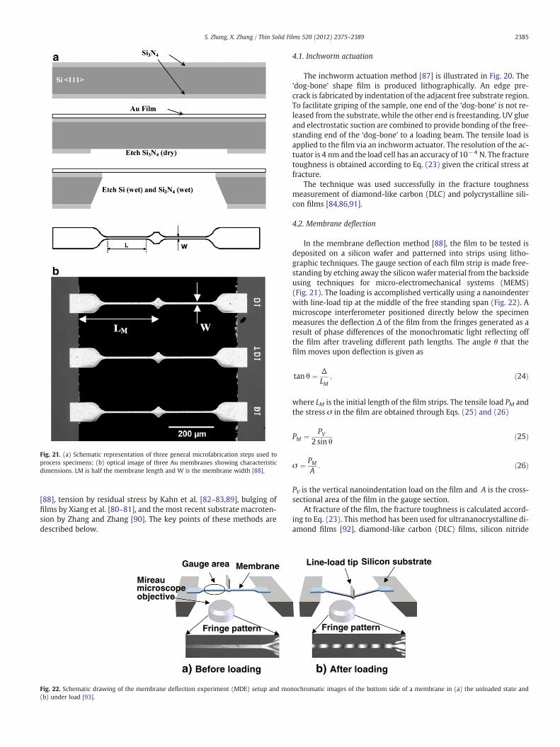
Fig. 21. (a) Schematic representation of three general microfabrication steps used toprocess specimens; (b) optical image of three Au membranes showing characteristicdimensions. LM is half the membrane length and W is the membrane width [88].
2385S. Zhang, X. Zhang / Thin Solid Films 520 (2012) 2375–2389
[88], tension by residual stress by Kahn et al. [82–83,89], bulging offilms by Xiang et al. [80–81], and the most recent substrate macroten-sion by Zhang and Zhang [90]. The key points of these methods aredescribed below.
a) Before loading
Fringe pattern
Gauge area Membrane
Mireaumicroscopeobjective
Fig. 22. Schematic drawing of the membrane deflection experiment (MDE) setup and mo(b) under load [93].
4.1. Inchworm actuation
The inchworm actuation method [87] is illustrated in Fig. 20. The‘dog-bone’ shape film is produced lithographically. An edge pre-crack is fabricated by indentation of the adjacent free substrate region.To facilitate griping of the sample, one end of the ‘dog-bone’ is not re-leased from the substrate, while the other end is freestanding. UV glueand electrostatic suction are combined to provide bonding of the free-standing end of the ‘dog-bone’ to a loading beam. The tensile load isapplied to the film via an inchworm actuator. The resolution of the ac-tuator is 4 nm and the load cell has an accuracy of 10−4 N. The fracturetoughness is obtained according to Eq. (23) given the critical stress atfracture.
The technique was used successfully in the fracture toughnessmeasurement of diamond-like carbon (DLC) and polycrystalline sili-con films [84,86,91].
4.2. Membrane deflection
In the membrane deflection method [88], the film to be tested isdeposited on a silicon wafer and patterned into strips using litho-graphic techniques. The gauge section of each film strip is made free-standing by etching away the silicon wafer material from the backsideusing techniques for micro-electromechanical systems (MEMS)(Fig. 21). The loading is accomplished vertically using a nanoindenterwith line-load tip at the middle of the free standing span (Fig. 22). Amicroscope interferometer positioned directly below the specimenmeasures the deflection Δ of the film from the fringes generated as aresult of phase differences of the monochromatic light reflecting offthe film after traveling different path lengths. The angle θ that thefilm moves upon deflection is given as
tan θ ¼ ΔLM
; ð24Þ
where LM is the initial length of the film strips. The tensile load PM andthe stress σ in the film are obtained through Eqs. (25) and (26)
PM ¼ PV2 sin θ
ð25Þ
σ ¼ PMA
: ð26Þ
PV is the vertical nanoindentation load on the film and A is the cross-sectional area of the film in the gauge section.
At fracture of the film, the fracture toughness is calculated accord-ing to Eq. (23). This method has been used for ultrananocrystalline di-amond films [92], diamond-like carbon (DLC) films, silicon nitride
Fringe pattern
Line-load tip Silicon substrate
b) After loading
nochromatic images of the bottom side of a membrane in (a) the unloaded state and

2386 S. Zhang, X. Zhang / Thin Solid Films 520 (2012) 2375–2389
(Si3N4) films [93–94], and single crystal silicon carbide (3C-SiC) [87],as well as gold, copper, and aluminum films [88,95–96].
4.3. Tension by residual stress
This is an ingenious way of loading: the residual tensile stress in athin film is used to serve as the loading to fracture the film in a frac-ture toughness measurement [82–83,89]. The film to be tested ismade into bridges with lithographic technologies (a film strip that
Fig. 23. Images of film bridges used to measure fracture toughness and stress corrosion. (a) Sa 60-μm-wide beam with an indentation placed near its center, a higher magnification SEMbeam. The indent was made on the SiO2 release layer, which was subsequently removed bybridges. The solid lines show the relations between K and a for three values of residual stre
is freestanding in the center while ends still adhere well to the sub-strate as shown in Fig. 23b). A sharp precrack is produced by indenta-tion in the film bridges before they are freestanding from substrate(Fig. 23a, c). The film bridges are stressed automatically due tounleashing of the residual stress. The stress intensity is related tothe initial crack length as shown by the K versus a curves inFig. 23d. The film bridges crack if the stress intensity factor is abovethe fracture toughness. Thus, the fracture toughness lies betweenthe stress intensity factors of the broken and unbroken bridges
chematic top view showing the dimensions. (b) Schematic side view. (c) SEM images ofof the area near the indent showing the precrack traveling from the substrate into thethe HF etching. (d) Plot of stress intensity K versus crack length a for polysilicon filmss. The dotted line is the fracture toughness KIC determined from these data [89].
Film
Si
Focused ion beam
Stress
Stress
b
a
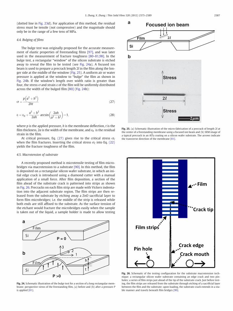
Fig. 25. (a) Schematic illustration of the micro-fabrication of a precrack of length 2l atthe center of a freestanding membrane using a focused ion beam and (b) SEM image ofa typical precrack in an AlTa coating on a silicon wafer substrate. The arrows indicatethe transverse direction of the membrane [81].
2387S. Zhang, X. Zhang / Thin Solid Films 520 (2012) 2375–2389
(dotted line in Fig. 23d). For application of this method, the residualstress must be tensile (not compressive) and the magnitude shouldonly be in the range of a few tens of MPa.
4.4. Bulging of films
The bulge test was originally proposed for the accurate measure-ment of elastic properties of freestanding films [97], and was laterused in the measurement of fracture toughness [80–81,98]. In thebulge test, a rectangular “window” of the silicon substrate is etchedaway to reveal the film to be tested (see Fig. 24a). A focused ionbeam is used to prepare a precrack length 2l in the film along the lon-ger side at the middle of the window (Fig. 25). A uniform air or waterpressure is applied at the window to “bulge” the film as shown inFig. 24b. If the window's length over width ratio is greater thanfour, the stress σ and strain ε of the film will be uniformly distributedacross the width of the bulged film [80] (Fig. 24b):
σ ¼p a2 þ h2� �
2htð27Þ
ε ¼ ε0 þa2 þ h2
2aharcsin
2aha2 þ h2
� �−1; ð28Þ
where p is the applied pressure, h is the membrane deflection, t is thefilm thickness, 2a is the width of the membrane, and ε0 is the residualstrain in the film.
At critical pressure, Eq. (27) gives rise to the critical stress σC
when the film fractures. Inserting the critical stress σC into Eq. (22)yields the fracture toughness of the film.
4.5. Macrotension of substrate
A recently proposed method is microtensile testing of film micro-bridges via macrotension to a substrate [90]. In this method, the filmis deposited on a rectangular silicon wafer substrate, in which an ini-tial edge crack is introduced using a diamond cutter with a manualapplication of a small force. After film deposition, a section of thefilm ahead of the substrate crack is patterned into strips as shownin Fig. 26. Precracks on each film strip are made with Vickers indenta-tion into the adjacent substrate region. The film strips are then re-leased from the substrate by etching away a ZnO sacrificial layer toform film microbridges; i.e. the middle of the strip is released whileboth ends are still affixed to the substrate. As the surface tension ofthe etchant would fracture the microbridges easily when the sampleis taken out of the liquid, a sample holder is made to allow testing
P = 0
P >0
a
b
Fig. 24. Schematic illustration of the bulge test for a section of a long rectangular mem-brane: perspective views of the freestanding film, (a) before and (b) after a pressure Pis applied [81].
Fig. 26. Schematic of the testing configuration for the substrate macrotension tech-nique: a rectangular silicon wafer substrate containing an edge crack and two pin-holes; a series of film strips just ahead of the tip of the substrate crack. Just before test-ing, the film strips are released from the substrate through etching of a sacrificial layerbetween the film and the substrate; upon loading, the substrate crack extends in a sta-ble manner and travels beneath film bridges [90].

2388 S. Zhang, X. Zhang / Thin Solid Films 520 (2012) 2375–2389
in water. On testing, a displacement controlled loading is applied tothe substrate by manually dialing a micrometer. The tensile loadingopens the substrate crack beneath the microbridges, causing the brid-ges to fracture (Fig. 26).
The film strain ε is measured through the extension δ of the filmduring testing,
ε ¼ δL0
: ð27Þ
L0 is the original length of the microbridge before loading. The exten-sion δ of the microbridge is measured by the extension of the substratecrack opening, which gives rise to a critical stress through Hooke's law,σ=Eε, as the ceramic film is assumed to fracture elastically. The frac-ture toughness is then calculated according to the Eq. (23).
The first advantage of the tension on substrate method lies in thefact that expensive equipment such as a focused ion beam is not re-quired. Only a precision micrometer is needed to carry out the test.Technically, using a ZnO release layer as a sacrificial layer (and thus0.25% HCl as the etchant) instead of a SiO2 layer (thus toxic HF asthe etchant) not only reduces the toxicity, but also allows testing ofalmost all ceramic films and even metallic films. The shortcoming ofthe method is its requirement of testing in water (to circumvent thesurface tension problem of the liquid etchant).
5. Summary
This article reviewed recent advances in fracture toughness mea-surements for hard coatings and thin films.
5.1. Hard coatings
For a hard coating well bonded on the substrate, the most com-mon qualitative methods used include indentation plasticity andscratch resistance; quantitatively, different methods are used basedon the type of cracking patterns upon indentation: radial cracking,channel cracking, and circumferential cracking and spallation.
The most common radial cracking method consists of the ultralowload indentation of the coating and measuring the lengths of resultingradial cracks. Once the length c is measured, the fracture toughness iscalculated via Eq. (7):
KC ¼ αEH
� �1=2 Pc3=2
� �:
This equation was adopted from indentation of bulk ceramics. Toapply on coatings, the load P has to be ultralow in order to avoid sub-strate effects. To use Eq. (7), however, the crack length must be atleast 2a (where a is half of the diagonal length of the indent). There-fore, problems always emerge in dealing with the substrate influenceand/or generation of a valid crack length.
When cracking starts with a “through-thickness” crack, it is termed“channel cracking”. The key to determine the fracture toughness of acoating is to obtain the critical stress σ; Eq. (17) is then used:
KI ¼ σ1−ν2
2πtg
!1=2
:
Bending of the substrate (multi-strain flexure) and sphere inden-tation of the coating, etc., have been used to generate channel crack-ing. The critical stress is obtained through the critical strain viaHooke's law. The method appears simple, but the parameter g in theequation is not explicit, which hinders the application of this method.
Channel cracking has also been generated through nanoindenta-tion of hard coatings on rigid substrates. The resultant formulation
is simple, but the assumption of rigidity of the substrate usuallydoes not apply.
Circumferential cracking and spallation take place during nanoin-dentation of hard, thus brittle, coatings on ceramic substrates. If theenergy released per fractured area (U/A) is obtained, the fracturetoughness of the coating is calculated through Eq. (12):
KC ¼ EU1−ν2� �
A
" #1=2:
Many authors obtain the fracture energy U from extrapolation ofthe load–displacement curve in which a step appears upon fracture.However, extraction of U from the step is controversial.
5.2. Thin films
Themost straightforward and reliable way of testing a thin film is toapply tension directly to the filmwhen it is “freestanding”. A number of“microtensile” methods have been used: inchworm actuation, mem-brane deflection, tension by residual stress, bulging, and the most re-cent “macrotension of substrate”. In all these method, the key is thedetermination of the critical stress σ of the film; then KI ¼ σ
ffiffiffiffiffiπl
p
Eq. (22) for a central crack or KI ¼ σffiffiffiffiffiffiπa
pf a=Wð Þ Eq. (23) for an edge
crack characterizes the fracture toughness. The formulation in micro-tensile testing is indeed very simple, but the difficulty lies in makingthe film freestanding, introducing a sharp precrack in the film, andclamping the film and applying a minute testing force. Technically, allthese are difficult to accomplish and usually require specific and dedi-cated apparatus.
The “macrotension of substrate” method developed recently pro-vides an extremely simple alternative, in which fracture forces are ap-plied to freestanding “microbridges” through macrotension of thesubstrate via a simple micrometer. This method cleverly solves theproblems of clamping a freestanding film and applying minute forceson it.
Acknowledgments
This work was supported by Project No. T208A1218 of the Minis-try of Education, Singapore, and partly by Project No. 51001084 of theNational Natural Science Foundation, China.
References
[1] G.E. Dieter, Mechanical Metallurgy, 2nd ed McGraw-Hill, 1976.[2] E.W. Wong, P.E. Sheehan, C.M. Lieber, Science 277 (5334) (1997) 1971.[3] D. Broek, Elementary Engineering Fracture Mechanics, 4th ed M. Nijhoff, 1986.[4] T. Anderson, Fracture Mechanics: Fundamental and Applications, CRC Press, Boca
Raton, FL, 2005.[5] H. Hosokawa, A.V. Desai, M.A. Haque, Thin Solid Films 516 (18) (2008) 6444.[6] Z. Jiang, F.X. Lu, W.Z. Tang, S.G. Wang, Y.M. Tong, T.B. Huang, J.M. Liu, Diamond
and related materials 9 (9–10) (2000) 1734.[7] ASTM1421-99, ASTM C 1421-99 Standard Test Methods 15.01, 1999.[8] ASTME-399, American Society for Testing and Materials, 1987.[9] A.A. Voevodin, J.S. Zabinski, Thin Solid Films 370 (1–2) (2000) 223.
[10] S. Zhang, X. Lam Bui, Y. Fu, Surf. Coat. Technol. 167 (2–3) (2003) 137.[11] G.S. Fox-Rabinovich, B.D. Beake, J.L. Endrino, S.C. Veldhuis, R. Parkinson, L.S. Shuster,
M.S. Migranov, Surf. Coat. Technol. 200 (20–21) (2006) 5738.[12] Y.T. Pei, D. Galvan, J.T.M. De Hosson, Acta Mater. 53 (17) (2005) 4505.[13] S. Zhang, X. Lam Bui, X.T. Zeng, X. Li, Thin Solid Films 482 (1–2) (2005) 138.[14] A.A. Voevodin, J.S. Zabinski, J. Mater. Sci. 33 (2) (1998) 319.[15] S. Zhang, D. Sun, Y. Fu, H. Du, Surf. Coat. Technol. 198 (1–3) (2005) 74.[16] Y.V. Milman, B.A. Galanov, S.I. Chugunova, Acta Metall. Mater. 41 (9) (1993) 2523.[17] A.A. Voevodin, S.V. Prasad, J.S. Zabinski, J. Appl. Phys. 82 (2) (1997) 855.[18] G.S. Fox-Rabinovich, S.C. Veldhuis, V.N. Scvortsov, L.S. Shuster, G.K. Dosbaeva,
M.S. Migranov, Thin Solid Films 469–470 (2004) 505.[19] S.J. Bull, Tribol. Int. 30 (7) (1997) 491.[20] P.W. Shum, K.Y. Li, Z.F. Zhou, Y.G. Shen, Surf. Coat. Technol. 185 (2–3) (2004) 245.[21] A.A. Voevodin, C. Rebholz, J.M. Schneider, P. Stevenson, A. Matthews, Surf. Coat.
Technol. 73 (3) (1995) 185.[22] E. Harry, A. Rouzaud, P. Juliet, Y. Pauleau, M. Ignat, Surf. Coat. Technol. 116 (1999)
172.
2389S. Zhang, X. Zhang / Thin Solid Films 520 (2012) 2375–2389
[23] J. Ligot, S. Benayoun, J.J. Hantzpergue, Wear 243 (1–2) (2000) 85.[24] S. Zhang, D. Sun, Y. Fu, H. Du, Thin Solid Films 447–448 (2004) 462.[25] J.W. Hoehn, S.K. Venkataraman, H. Huang, W.W. Gerberich, Mater. Sci. Eng., A
192–193 (Part 1) (1995) 301.[26] K. Holmberg, A. Laukkanen, H. Ronkainen, K. Wallin, S. Varjus, Wear 254 (3–4)
(2003) 278.[27] G.M. Pharr, Mater. Sci. Eng., A 253 (1–2) (1998) 151.[28] B.R.L.a.A.G. Evans, J. Am. Ceram. Soc. 63 (1980).[29] A.G. Evans, E.A. Charles, J. Am. Ceram. Soc. 59 (7–8) (1976) 371.[30] G.R. Anstis, P. Chantikul, B.R. Lawn, D.B. Marshall, J. Am. Ceram. Soc. 64 (9) (1981)
533.[31] D.B. Marshall, B.R. Lawn, J. Am. Ceram. Soc. 60 (1–2) (1977) 86.[32] D. Broek, Elementary Engineering Fracture Mechanics, Kluwer Academic Pub-
lishers, Dordrecht, 1997.[33] J. Lankford, D.L. Davidson, J. Mater. Sci. 14 (7) (1979) 1662.[34] X. Li, D. Diao, B. Bhushan, Acta Mater. 45 (11) (1997) 4453.[35] A.C.-S.T. Methods, 15.01, 1999.[36] A. Leonardi, F. Furgiuele, R.J.K. Wood, S. Syngellakis, Eng. Fract. Mech. 77 (2)
(2010) 264.[37] K. Niihara, J. Mater. Sci. Lett. 2 (5) (1983) 221.[38] J.J. Kruzic, R.O. Ritchie, J. Biomech. 41 (6) (2008) 1379.[39] G.D. Quinn, R.C. Bradt, J. Am. Ceram. Soc. 90 (3) (2007) 673.[40] M. Sakai, R.C. Bradt, Int. Mater. Rev. 38 (2) (1993) 53.[41] R.F. Cook, G.M. Pharr, J. Am. Ceram. Soc. 73 (4) (1990) 787.[42] T.Y. Zhang, L.Q. Chen, R. Fu, Acta Mater. 47 (14) (1999) 3869.[43] Z.H. Xia, W.A. Curtin, B.W. Sheldon, Acta Mater. 52 (12) (2004) 3507.[44] J. den Toonder, J. Malzbender, G. de With, R. Balkenende, J. Mater. Res. 17 (1)
(2002) 224.[45] J. Chen, S.J. Bull, Thin Solid Films 494 (1–2) (2006) 1.[46] M.D. Michel, L.V. Muhlen, C.A. Achete, C.M. Lepienski, Thin Solid Films 496 (2)
(2006) 481.[47] J. Chen, S.J. Bull, Thin Solid Films 517 (9) (2009) 2945.[48] Y.T. Cheng, Z.Y. Li, C.M. Cheng, Phil. Mag A 82/10 (2002) 1821.[49] J. Malzbender, J.M.J. den Toonder, A.R. Balkenende, G. de With, Mater. Sci. Eng. R:
Rep. 36 (2–3) (2002) 47.[50] J. Malzbender, G. de With, Surf. Coat. Technol. 135 (1) (2000) 60.[51] J. Chen, S.J. Bull, J. Phys. D:Appl. Phys. 40 (18) (2007) 5401.[52] S.V. Hainsworth, T. Bartlett, T.F. Page, Thin Solid Films 236 (1–2) (1993) 214.[53] T.F. Page, S.V. Hainsworth, Surf. Coat. Technol. 61 (1–3) (1993) 201.[54] R. Rabe, J.M. Breguet, P. Schwaller, S. Stauss, F.J. Haug, J. Patscheider, J. Michler,
Thin Solid Films 469–470 (2004) 206.[55] D.F. Bahr, J.W. Hoehn, N.R. Moody, W.W. Gerberich, Acta Mater. 45 (12) (1997)
5163.[56] A.J. Haq, P.R. Munroe, M. Hoffman, P.J. Martin, A. Bendavid, J. Mater. Res. 23 (7)
(2008) 1862.[57] A.J. Whitehead, T.F. Page, Thin Solid Films 220 (1–2) (1992) 277.[58] A.J. Haq, P.R. Munroe, M. Hoffman, P.J. Martin, A. Bendavid, Thin Solid Films 518
(8) (2010) 2021.[59] D.B. Marshall, A.G. Evans, J. Appl. Phys. 56 (10) (1984) 2632.[60] A.G. Evans, J.W. Hutchinson, Int. J. Solids Struct. 20 (5) (1984) 455.[61] J.W. Hutchinson, Z. Suo, Adv. Appl. Mech. Vol 29 (1992) 63.
[62] M.Y. He, J.W. Hutchinson, J. Appl. Mech. 56 (1989) 270.[63] X.M. Zhang, S. Zhang, Thin solid films submitted (2011).[64] J.L. Beuth, Int. J. Solids Struct. 29 (13) (1992) 1657.[65] Z.C. Xia, J.W. Hutchinson, J. Mech. Phys. Solids 48 (6–7) (2000) 1107.[66] J.L. Beuth, N.W. Klingbeil, J. Mech. Phys. Solids 44 (9) (1996) 1411.[67] M.R. Begley, A.G. Evans, J.W. Hutchinson, Int. J. Solids Struct. 36 (18) (1999) 2773.[68] J.S. Wang, Y. Sugimura, A.G. Evans, W.K. Tredway, Thin Solid Films 325 (1–2)
(1998) 163.[69] D.K. Leung, N.T. Zhang, R.M. McMeeking, A.G. Evans, J. Mater. Res. 10 (8) (1995)
1958.[70] D.K. Leung, M.Y. He, A.G. Evans, J. Mater. Res. 10 (7) (1995) 1693.[71] J.M. Jungk, B.L. Boyce, T.E. Buchheit, T.A. Friedmann, D. Yang, W.W. Gerberich,
Acta Mater. 54 (15) (2006) 4043.[72] J. Thurn, R.F. Cook, J. Mater. Sci. 39 (15) (2004) 4809.[73] T.Y. Tsui, J. Vlassak, W.D. Nix, J. Mater. Res. 14 (6) (1999) 2196.[74] T.Y. Tsui, J. Vlassak, W.D. Nix, J. Mater. Res. 14 (6) (1999) 2204.[75] R.F. Cook, J. Am. Ceram. Soc. 77 (5) (1994) 1263.[76] Murakami, Stress Intensity Factors Handbook, Pergamon, Oxford, 1987.[77] R. Ballarini, R.L. Mullen, Y. Yin, H. Kahn, S. Stemmer, A.H. Heuer, J. Mater. Res. 12
(4) (1997) 915.[78] M.A. Haque, M.T.A. Saif, Exp. Mech. 42 (1) (2002) 123.[79] M.A. Haque, M.T.A. Saif, Exp. Mech. 43 (3) (2003) 248.[80] Y. Xiang, X. Chen, J.J. Vlassak, J. Mater. Res. 20 (9) (2005) 2360.[81] Y. Xiang, J. McKinnell, W.M. Ang, J.J. Vlassak, Int. J. Fract. 144 (3) (2007) 173.[82] V. Hatty, H. Kahn, J. Trevino, C.A. Zorman, M. Mehregany, R. Ballarini, A.H. Heuer,
J. Appl. Phys. 99 (1) (2006).[83] J.J. Bellante, H. Kahn, R. Ballarini, C.A. Zorman, M. Mehregany, A.H. Heuer, Appl.
Phys. Lett. 86 (7) (2005).[84] K. Jonnalagadda, S.W. Chob, L. Chasiotisa, T. Friedmannc, J. Sullivanc, J. Mech.
Phys. Solids 56 (2) (2008) 388.[85] I. Chasiotis, W.G. Knauss, Exp. Mech. 42 (1) (2002) 51.[86] S.W. Cho, K. Jonnalagadda, I. Chasiotis, Fatigue Fract. Eng. Mater. Struct. 30 (1)
(2007) 21.[87] H.D. Espinosa, B. Peng, N. Moldovan, T.A. Friedmann, X. Xiao, D.C. Mancini, O.
Auciello, J. Carlisle, C.A. Zorman, M. Merhegany, Appl. Phys. Lett. 89 (7) (2006).[88] H.D. Espinosa, B.C. Prorok, M. Fischer, J. Mech. Phys. Solids 51 (1) (2003) 47.[89] H. Kahn, R. Ballarini, J.J. Bellante, A.H. Heuer, Science 298 (5596) (2002) 1215.[90] X.M. Zhang, S. Zhang, Nanoscience and Nanotechnology Letters 3 (6) (2011)
735–743.[91] I. Chasiotis, S.W. Cho, K. Jonnalagadda, J. Appl. Mech.-Trans. ASME 73 (5) (2006)
714.[92] B. Peng, C. Li, N. Moldovan, H.D. Espinosa, X. Xiao, O. Auciello, J.A. Carlisle, J. Mater.
Res. 22 (4) (2007) 913.[93] B. Peng, N. Pugno, H.D. Espinosa, Int. J. Solids Struct. 43 (11–12) (2006) 3292.[94] N. Pugno, B. Peng, H.D. Espinosa, Int. J. Solids Struct. 42 (2) (2005) 647.[95] H.D. Espinosa, B.C. Prorok, J. Mater. Sci. 38 (20) (2003) 4125.[96] H.D. Espinosa, B.C. Prorok, B. Peng, J. Mech. Phys. Solids 52 (3) (2004) 667.[97] J.J. Vlassak, W.D. Nix, J. Mater. Res. 7 (12) (1992) 3242.[98] B. Merle, M. Göken, Acta Mater. 59 (4) (2011) 1772.