thickness measurement of circular metallic film using
TRANSCRIPT

Thickness measurement of circular metallic film using single-frequency
eddy current sensor
Mingyang Lua,1,*, Xiaobai Mengb,1, Ruochen Huanga,*, Liming Chena, Anthony Peytona, Wuliang Yina,*
a School of Electrical and Electronic Engineering, University of Manchester, Oxford Road, Manchester, M13 9PL, UK b Faculty of Art, Science and Technology, University of Northampton, Northampton, NN1 5PH, UK 1 M. Lu and X. Meng contributed equally and share the first authorship.
*Corresponding author: [email protected]; [email protected]; [email protected];
Abstract – In many advanced industrial applications, the thickness is a critical index, especially for metallic
coatings. However, the variance of lift-off spacing between sensors and test pieces affects the measured voltage
or impedance, which leads to unreliable results from the sensor. Massive research works have been proposed to
address the lift-off issue, but few of them applies to the thickness measurement of planar metallic films with finite-
size circular (disk) geometry. Previously, a peak-frequency feature from the swept-frequency inductance was used
to compensate the measurement error caused by lift-offs, which was based on the slow-changing rate of impedance
phase term in the Dodd-Deeds formulas. However, the phase of measured impedance is nearly invariant merely
on a limited range of sample thicknesses and working frequencies. Besides, the frequency sweeping is time-
consuming, where a recalibration is needed for different sensor setups applied to the online real-time measurement.
In this paper, a single-frequency algorithm has been proposed, which is embedded in the measurement instrument
for the online real-time retrieval of thickness. Owing to the single-frequency measurement strategy, the proposed
method does not need to recalibrate for different sensor setups. The thickness retrieval is based on a triple-coil
sensor (with one transmitter and two receivers). The thickness of metallic disk foils is retrieved from the measured
electrical resistance of two transmitter-receiver sensing pairs. Experiments on materials of different electrical
conductivities (from direct current), thicknesses and planar sizes (radii) have been carried out to verify the
proposed method. The error for the thickness retrieval of conductive disk foils is controlled within 5 % for lift-
offs up to 5 mm.
Index Terms – Eddy current testing, thickness measurement, finite-size, lift-off effect, non-destructive testing.
Introduction
Electromagnetic (EM) eddy current testing (ECT) [1-7] is one of promising technologies in the non-destructive
testing, which applies to the evaluation of product quality (e.g., inspecting the crack fatigue, measuring the
inhomogeneity or monitoring the variance of the property) [8-14]. The thickness measurement system has the
potential application of inspecting the structural integrity and surface notches of metals, particularly for
conductive coatings. Both the multi-frequency eddy current sensors, swept-frequency eddy current sensors, and
pulsed eddy current (PEC) sensors have been used for the thickness measurement of metallic plates or foils (e.g.,
coatings or claddings) [15-24]. However, it is found that the variance of sample-sensor lift-offs significantly
affects the measured voltage or impedance of sensors, which influences the accuracy on thickness retrieval.
Many techniques have been used for eliminating the lift-off effect when using both the multi-frequency eddy
current sensors, swept-frequency eddy current sensors, and pulsed eddy current (PEC) sensors, including custom
embedded algorithms, new sensor designs, and novel time-domain and frequency-domain features. Tai et al. have
introduced a custom-built instrument for determining the thickness and electrical conductivity of coatings using
PEC sensors [21]. Wang et al. have proposed a novel feature from the slope of the lift-off curve for reducing the
lift-off error on the thickness measurement of metallic films [22]. Pinotti et al. proposed a lock-in method to
extract the phase signature and linked it to the electrical conductivity and thickness of conductive coatings [23].
Mandache et al. have found a lift-off point of intersection (LOI) feature in the transient and harmonic eddy currents
[24]. Fan et al. have used the LOI feature for reducing the lift-off effect on the thickness measurement when using
the PEC method [25]. Angani et al. have used the LOI feature for the detection of corrosion and thickness
measurement of stainless-steel plates [26]. These methods are efficient on the thickness measurement but cannot
apply to the thickness measurement of finite-size circular plates.
In our previous research works, various techniques have been proposed for reducing the lift-off effect,
including the peak frequency feature in swept-frequency inductance spectra, and novel sensor designs for the
single-frequency testing [27-32]. The peak frequency feature is based on the slow-changing rate of impedance
phase term in the Dodd-Deeds model. However, the changing rate of impedance phase term is neglectable merely
on a limited range of sample thicknesses.
Preprints (www.preprints.org) | NOT PEER-REVIEWED | Posted: 9 February 2021 doi:10.20944/preprints202102.0237.v1
© 2021 by the author(s). Distributed under a Creative Commons CC BY license.

A single-frequency algorithm is proposed in this paper, which is used to reduce the lift-off effect on retrieving
the thickness of metallic films with finite-size circular geometry. The algorithm is based on the modified Dodd-
Deeds model [30, 34]. Instead of integrating from zero (for the infinite plate) [33], for the case of finite-size disk
sample, the algorithm of mutual impedance is revised by integrating from a constant value in the Dodd-Deeds
model. By combining the single-frequency impedance measured from two transmitter-receiver sensing pairs, the
thickness of conductive disk foils is retrieved and less affected by the lift-off of sensors. Experiments on finite
disk plates with different electrical conductivities, actual thicknesses and radii have been carried out for the
validation of the proposed algorithm.
Methodology – algorithm for the thickness measurement of no-ferrous metal plate with finite-size
circular geometry
Both the lift-off of sensors and properties of samples (including the thickness, magnetic permeability,
electrical conductivity) affect the detected signal (voltage, mutual impedance, or inductance) of the
electromagnetic eddy current sensor. However, the lift-off (or lift-off variance) of sensors is an unknown
parameter in most of occasions and applications. Besides, the sensor response is very sensitive to its lift-off to the
sample. Thus, in Fig. 1, for the thickness measurement of a non-ferrous circular metal plate, an air coil sensor
with two sensing pairs has been designed to address the issue caused by sensor lift-offs.
Fig. 1 Three coils co-axially above a finite-size circular plate
Dodd-Deeds analytical model has been proposed over a few decades but is still the most dominant method for
the problem of a coil above an infinite plate [33].
From our previous research works, the modified Dodd-Deeds model has been proposed for the problem of
circular coils above a finite-size circular disk plate [30, 34]. By integrating the previous derived magnetic vector
potential in region 1 and 2, the impedance change (subtract of the impedance for the presence and absence of the
specimen) tested by two sensing pairs can be derived as,
ΔZ1 = jωr̅K ∫P(α)
α6 A1(α)∞
αt
ϕ(α)dα (1)
ΔZ2 = jωr̅K ∫P(α)
α6A2(α)
∞
αt
ϕ(α)dα (2)
ω is the working angular frequency. K is a coil factor and defined in (3). α is related to the wavenumber of
incident transverse electric (TE) planar electromagnetic wave [33-43]. P(α) is the integration of Bessel terms
defined in (10). A1(α) and A2(α) are the coil-dependent term defined in (8) and (9). ϕ(α) is a complex term
determined by the test piece (i.e. circular metallic plate), and defined in (6).
K =πN2μ0
h2∆r2 (3)
N and h are the identical turns and height of the transmitter coil (T), receiver coil (P1) and reference coil (P2).
μ0 is the vacuum permeability. r̅ and ∆r are the mean radii and difference between the outer radius r2 and inner
radius r1 of three coils, which is defined in (4).
r̅ =r1 + r2
2, ∆r =
r2 − r1
2 (4)
Preprints (www.preprints.org) | NOT PEER-REVIEWED | Posted: 9 February 2021 doi:10.20944/preprints202102.0237.v1
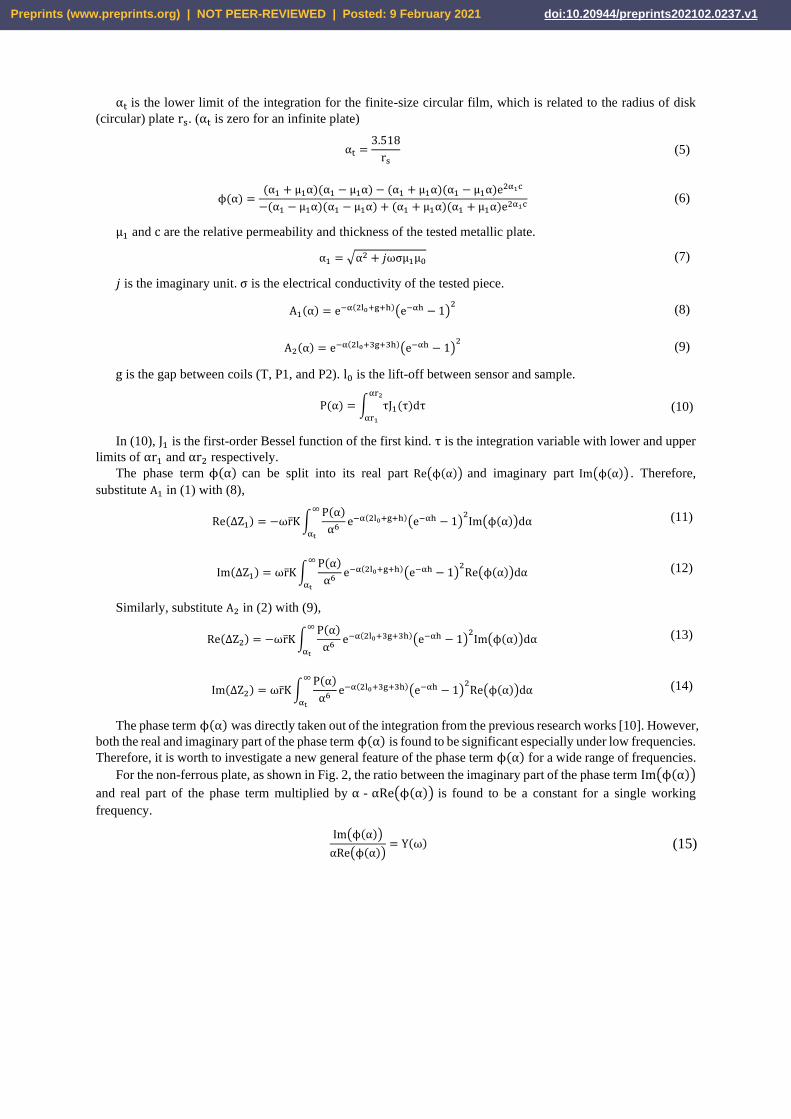
αt is the lower limit of the integration for the finite-size circular film, which is related to the radius of disk
(circular) plate rs. (αt is zero for an infinite plate)
αt =3.518
rs (5)
ϕ(α) =(α1 + μ1α)(α1 − μ1α) − (α1 + μ1α)(α1 − μ1α)e2α1c
−(α1 − μ1α)(α1 − μ1α) + (α1 + μ1α)(α1 + μ1α)e2α1c (6)
μ1 and c are the relative permeability and thickness of the tested metallic plate.
α1 = √α2 + 𝑗ωσμ1μ0 (7)
𝑗 is the imaginary unit. σ is the electrical conductivity of the tested piece.
A1(α) = e−α(2l0+g+h)(e−αh − 1)2
(8)
A2(α) = e−α(2l0+3g+3h)(e−αh − 1)2 (9)
g is the gap between coils (T, P1, and P2). l0 is the lift-off between sensor and sample.
P(α) = ∫ τJ1(τ)dταr2
αr1
(10)
In (10), J1 is the first-order Bessel function of the first kind. τ is the integration variable with lower and upper
limits of αr1 and αr2 respectively.
The phase term ϕ(α) can be split into its real part Re(ϕ(α)) and imaginary part Im(ϕ(α)) . Therefore,
substitute A1 in (1) with (8),
Re(ΔZ1) = −ωr̅K ∫P(α)
α6 e−α(2l0+g+h)(e−αh − 1)2
Im(ϕ(α))dα∞
αt
(11)
Im(ΔZ1) = ωr̅K ∫P(α)
α6e−α(2l0+g+h)(e−αh − 1)
2Re(ϕ(α))dα
∞
αt
(12)
Similarly, substitute A2 in (2) with (9),
Re(ΔZ2) = −ωr̅K ∫P(α)
α6e−α(2l0+3g+3h)(e−αh − 1)
2Im(ϕ(α))dα
∞
αt
(13)
Im(ΔZ2) = ωr̅K ∫P(α)
α6e−α(2l0+3g+3h)(e−αh − 1)
2Re(ϕ(α))dα
∞
αt
(14)
The phase term ϕ(α) was directly taken out of the integration from the previous research works [10]. However,
both the real and imaginary part of the phase term ϕ(α) is found to be significant especially under low frequencies.
Therefore, it is worth to investigate a new general feature of the phase term ϕ(α) for a wide range of frequencies.
For the non-ferrous plate, as shown in Fig. 2, the ratio between the imaginary part of the phase term Im(ϕ(α))
and real part of the phase term multiplied by α - αRe(ϕ(α)) is found to be a constant for a single working
frequency.
Im(ϕ(α))
αRe(ϕ(α))= Y(ω) (15)
Preprints (www.preprints.org) | NOT PEER-REVIEWED | Posted: 9 February 2021 doi:10.20944/preprints202102.0237.v1

Fig. 2 Im(ϕ(α))
αRe(ϕ(α)) versus α under different working frequencies
The frequency-dependent constant Y can be calculated by finding its limit at α = 0.
Y = limα→0
Im(ϕ(α))
αRe(ϕ(α)) (16)
Equation (16) can be solved using Wolfram, as shown in equation (17).
Y =√2 (1 + e2c√2ωσμ0)
√ωσμ0 (e2c√2ωσμ0 − 2ec√2ωσμ0cos(c√2ωσμ0) + 1) (17)
Since term c√2ωσμ0 is not significant for the thin film, equation (17) can be simplified using the Padé
approximation.
Y =1
√2ωσμ0
(1 +1
c2ωσμ0) (18)
As shown in Fig. 3, the real part of the phase term ϕ(α) is found to be varying slowly with α. In (19), an
exponential function with its power controlled by a small factor G is used to approximate Re(ϕ(α)). The factor
G is determined by the working frequency ω, electrical conductivity σ, and sample thickness c.
Re(ϕ(α)) = −e−2αG (19)
Fig. 3 Approximation of Re(ϕ(α)) using −e−2αG under different working frequencies
Preprints (www.preprints.org) | NOT PEER-REVIEWED | Posted: 9 February 2021 doi:10.20944/preprints202102.0237.v1

Assign Re(ΔZ1) and Re(ΔZ2) to be R1 and R2. Substitute (15) and (19) into (11)-(14), the electrical resistance
change (real parts) and imaginary parts of the impedance change from T-P1 and T-P2 sensing pairs are,
R1 = ωYr̅K ∫P(α)
α5 e−α(2l0+g+h)(e−αh − 1)2
e−2αG∞
αt
dα (20)
Im(ΔZ1) = −ωr̅K ∫P(α)
α6 e−α(2l0+g+h)(e−αh − 1)2
e−2αG∞
αt
dα (21)
R2 = ωYr̅K ∫P(α)
α5e−α(2l0+3g+3h)(e−αh − 1)
2e−2αG
∞
αt
(22)
Im(ΔZ2) = −ωr̅K ∫P(α)
α6 e−α(2l0+3g+3h)(e−αh − 1)2
e−2αG∞
αt
dα (23)
(a)
(b) (c)
Fig. 4 (a) The first pulse and second pulse of Bessel series for T-P1 sensing pair (b) Approximation of second-pulse Bessel series for T-P1
sensing pair (c) Approximation of second-pulse Bessel series for T-P2 sensing pair
As Fig. 4 (b) and (c) depict, the Bessel series in (20) and (22) can be estimated as squared sinusoidal functions,
as shown in followings,
First pulse
Second pulse
α = αt
2s0
α = αt
2s0′
Preprints (www.preprints.org) | NOT PEER-REVIEWED | Posted: 9 February 2021 doi:10.20944/preprints202102.0237.v1

R1 = ωYr̅K ∫P(α)
α5e−α(2l0+g+h)(e−αh − 1)
2e−2αG
∞
αt
= ωYr̅KM1 ∫ e−2α(l0+G)sin2 ((2s0 − α)π
2b0) dα
2s0
αt
(24)
R2 = ωYr̅K ∫P(α)
α5 e−α(2l0+3g+3h)(e−αh − 1)2
e−2αG∞
αt
= ωYr̅KM1 ∫ e−2α(l0+G)sin2 ((2s0
′ − α)π
2b0′ ) dα
2s0′
αt
(25)
In (24) and (25), both s0, b0, s0′ , and b0
′ are used to approximate the Bessel terms in (20) and (22), which are
determined by the sensor geometry. The variables s0, b0, s0′ , and b0
′ are similar to the spatial frequency proposed
in previous research works [10,29]. The spatial frequency in previous work is used to approximate the first pulse
of the Bessel series. However, since αt is located on the second pulsed of Bessel series (for a finite-size circular
plate), more spatial frequency parameters (variables s0, b0, s0′ , and b0
′ ) are needed for approximating the peak
position and bandwidth of the second pulse of Bessel series. As can be seen from Fig. 4 (b) and (c), s0 and s0′
control the upper limit of the integration. Besides, b0 and b0′ define the peak value points of the sinusoidal
functions. M1 and M2 are the normalization factor between the Bessel and sinusoidal functions for both T-P1 and
T-P2 sensing pairs, which are defined as followings,
M1 =P(2s0 − b0)
(2s0 − b0)5e−(2s0−b0)(g+h)(e−(2s0−b0)h − 1)
2 (26)
M2 =P(2s0
′ − b0′ )
(2s0′ − b0
′ )5 e−3(2s0′ −b0
′ )(g+h)(e−(2s0′ −b0
′ )h − 1)2 (27)
After the integration, equation (24) becomes,
R1 =ωYr̅KM1
4(l0 + G)(4b02(l0 + G)2 + π2)
(e−2αt(l0+G)(4b02(l0 + G)2
(1 − cos ((2s0 − αt)π
b0)) + 2πb0(l0 + G)sin (
(2s0 − αt)π
b0) + π2) − π2e−4s0(l0+G))
(28)
Since b0(l0 + G) ≪ π, (28) becomes,
R1 = ωYr̅KM1
e−2αt(l0+G) − e−4s0(l0+G)
4(l0 + G) (29)
According to the Padé approximation, e−2αt(l0+G)and e−4(α0+b0)(l0+G) in (29) can be approximate as,
e−2αt(l0+G) = −αt(l0 + G) − 1
αt(l0 + G) + 1 (30)
e−4(α0+b0)(l0+G) = −2s0(l0 + G) − 1
2s0(l0 + G) + 1 (31)
Substitute (30) and (31) into (29), R1 becomes,
R1 = ωYr̅KM1
(2s0 − αt)
2(αt(l0 + G) + 1)(2s0(l0 + G) + 1) (32)
Similarly, the resistance from T-P2 sensing pair is
R2 = ωYr̅KM2
(2s0′ − αt)
2(αt(l0 + G) + 1)(2s0′ (l0 + G) + 1)
(33)
Combine (32) with (33), the proportional factor Y is,
Y =R1R2(M2R1 − M1R2)(2s0
2(2s0′ − αt) + 2s0
′2(αt − 2s0) + αt2(s0 − s0
′ ))
ωr̅K(R1s0M2(2s0′ − αt) − R2s0
′ M1(2s0 − αt))2 (34)
Preprints (www.preprints.org) | NOT PEER-REVIEWED | Posted: 9 February 2021 doi:10.20944/preprints202102.0237.v1

Combine (34) with (18), the thickness of the circular film can be reconstructed as,
c =1
√ωσμ0√2ωσμ0Y − 1
(35)
Experimental verification
As shown in Fig. 5, experiments have been conducted on the mutual impedance measurement of an air-core
sensor co-axially deployed (with lift-offs from 1 mm to 5 mm) above circular aluminium and copper foils. As
listed in Table 1, the sensor has three coils with identical parameters, with one transmitter coil, one receiver coil,
and one reference coil spirally wound and equally separated on the same cylindrical tube (plastic).
Fig. 5 Experimental configuration – eddy current coils are co-axially placed above aluminium and copper disk laminates with different lift-
offs; Impedance analyser is connected to the sensing coil to measure the mutual impedance under different working frequencies of alternating
currents flowing in coils.
Table 1 Sensor Parameters
T, P1, P2 coils
Inner radius (mm) 28
28.25 Outer radius (mm)
Turns 20
Coils gap (mm) 3.00
Coils height (mm) 5.00
Lift-offs (mm) 1.00:1.00:5.00
Table 2 Geometry and property of the metallic films
Aluminium Copper
Radius (mm) 20.0 15.0, 17.5, 20.0
Actual thickness 22, 44, 66 μm 0.5 mm
Electrical conductivity
(MS/m) 35 57
As listed in Table 2, the aluminium films have an identical radius of 20 mm, but different actual thicknesses.
While the copper films have different radii but an identical thickness of 0.5 mm. The electrical conductivity of
both samples is measured using the 4-terminal sensing method. Both samples are selected for testing the accuracy
of the proposed method on different parameters (radius, thickness, and electrical conductivity).
MFIA Zurich impedance analyser
Eddy current sensing coils
Preprints (www.preprints.org) | NOT PEER-REVIEWED | Posted: 9 February 2021 doi:10.20944/preprints202102.0237.v1

In the measurement, three coils of sensor were connected to the impedance analyser. To test the performance
of proposed method under different single frequencies, the measurement was tested under a reasonable range of
working frequencies from 1 kHz to 500 kHz (to get rid of the noise signal and resonance distortion under lower
and higher frequencies).
Results and discussions
A. Measurement of resistance
(a) (b)
Fig. 6 Measurement of electrical resistance for the aluminium film of 22, 44, and 66 μm under a sensor lift-off of 2 and 4 mm (a) T-P1 sensing
pair (b) T-P2 sensing pair
Fig. 6 and Fig. 7 illustrate the measured electrical resistance under different working frequencies and sensor
lift-offs (2 mm and 4 mm). For both aluminium films with different actual thicknesses and copper films with
different radii, the measured resistance is shown to be increasing with working frequencies. The measured
resistance for a sensor above a metallic sample is related to the skin depth of the eddy current flowing in the
sample. Under the high frequencies, the eddy current is restrained underneath the surface of the sample, which is
named as the eddy current skin effect or the eddy current diffusion effect. Moreover, due to the weakened
interaction between the sensor and sample, the increase in sensor lift-off leads to reduced resistance. Consequently,
the measured resistance of T-P2 sensing pair is lower than that of T-P1 sensing pair. As Fig. 6 depicts, under high
working frequencies, the resistance of thin aluminium films is larger than that of thicker films. This is because the
eddy current flowing in the thin film is more restrained under its lower surface. However, further increased
frequency will result in overlap for the curves (over 15 MHz for skin depth of less than 22 μm, not shown in Fig.
6) of different thicknesses due to the eddy current skin effect. In Fig. 7, the measured resistance for the copper
film of a larger radius is larger than that of a smaller radius due to more volume of resistant eddy current or
fortified coupling effect between the sensor and sample.
(a) (b)
Fig. 7. Measurement of electrical resistance for the copper film with radii of 15 mm, 17.5 mm and 20 mm under a sensor lift-off of 2 and 4
mm (a) T-P1 sensing pair (b) T-P2 sensing pair
Preprints (www.preprints.org) | NOT PEER-REVIEWED | Posted: 9 February 2021 doi:10.20944/preprints202102.0237.v1

B. Reconstructed thickness for different working frequencies
The thickness of both the aluminium film (with different actual thickness) and copper film (with different
radii) can be reconstructed by inputting the measured electrical resistance into (34) and (35). As shown in Fig. 8,
for both materials, the reconstructed thickness was found to be reduced with increased single operation frequency.
It can be observed that the optimal single operation frequency (using the designed sensor) for both materials is
around 16 kHz (since the variables s0, b0, s0′ , and b0
′ in 24, 25, and 34 are fitted at this frequency). The distorted
thickness in Fig. 8 for frequencies apart from the optimal value (16 kHz) is mainly due to the discrepancy of coil
windings between the experimental and analytical setups. In the analytical setup, the coil winding is modelled as
seamless turns of coils with cubic cross-section; while in the experiment, the coils are wound with wires of circular
cross-section. Besides, the variation of frequency could result in different off-set impedance due to the fringe
effect of current flowing in turns of coil. Thus, for an alternative single frequency (small enough to ensure that
the skin depth is larger than the actual thickness), the variables s0, b0, s0′ , and b0
′ in 24, 25, and 34 need to be
refitted. In addition, the effect of the sensor lift-off (a small lift-off of less than 5 mm) is significantly reduced for
the derived thickness (both aluminium with different thicknesses and copper films with different radii), with the
curve of 5 mm sensor lift-off slightly larger than that of 1 mm sensor lift-off. Moreover, the reconstructed
thickness for the copper film is approaching zero (distorted) under high frequencies, which is due to the reduced
skin depth (lower than the actual thickness – 0.5 mm when the frequency is larger than 18 kHz). Besides, in Fig.
8 (b), it can be seen that the reconstructed thickness is almost immune to the different radii.
(a) (b)
Fig. 8 Reconstructed thickness under different operating single-frequencies with sensor lift-off of 1 and 5 mm (a) aluminium film with a
thickness of 22, 44, and 66 μm (b) copper film with radii of 15, 17.5, and 20 mm
C. Wobble effect between sample and coil
Fig. 9 Reconstructed thickness under different offsets between the axis of sample and coils with sensor lift-off of 1 and 5 mm (a) aluminium
film with a thickness of 22, 44, and 66 μm (b) copper film with radii of 15, 17.5, and 20 mm
Zoom in
Preprints (www.preprints.org) | NOT PEER-REVIEWED | Posted: 9 February 2021 doi:10.20944/preprints202102.0237.v1

Fig. 9 shows the retrieved thickness for different offsets between the axis of sample and coils. It can be
observed that a wobble between the sample and coils results in an increased retrieved thickness, which is due to
the reduced electrical resistance measured from coils. For a maximum offset of 6 mm, the error of retrieved
thickness for both materials are controlled within 10 %. Further offsets between the axis of sample and coils will
lead to a significantly increased error of thickness retrieval.
D. Reconstructed thickness for different sensor lift-offs
(a) (b)
Fig. 10 Reconstructed thickness of aluminium films under the optimal frequency of 16 kHz with different sensor lift-offs (a) absolute value (b)
error with respect to the actual thickness
Since the thickness is found can be accurately reconstructed at the optimal frequency - 16 kHz for both
aluminium films with different actual thicknesses and copper films with different radii, it is worth further
investigating the lift-off effect on the reconstructed thickness under the optimal working frequency. In Fig. 10, it
can be observed that the thickness of aluminium films (for different actual thicknesses) can be reconstructed with
a small error of less than 3.5 %. Moreover, thickness after the reconstruction is gradually stable with the increased
sensor lift-off, with the aluminium film of 66 μm the highest absolute reconstruction error. In Fig. 11, a similar
trend (reduced and stable error for increased sensor lift-offs) can be seen on the reconstructed thickness of the
copper films with different radii. The error of the thickness reconstruction for copper films is around 5 %.
Moreover, the difference between the thickness curves of different radii is not significant after the reconstruction.
In the experimental, the sensor lift-off is selected to be a series of small values of less than 5 mm, since larger
sensor lift-off will result in a distorted value due to the extremely weak coupling effect between sensor and sample.
(a) (b)
Fig. 11 Reconstructed thickness of copper films under the optimal frequency of 16 kHz with different sensor lift-offs (a) absolute value (b)
error with respect to the actual thickness
Preprints (www.preprints.org) | NOT PEER-REVIEWED | Posted: 9 February 2021 doi:10.20944/preprints202102.0237.v1

Conclusions
In this paper, to address the lift-off issue on the thickness measurement of conductive (finite) disk films, a
single-frequency algorithm has been proposed based on the eddy current method. By inputting the measured
resistance (i.e., the real part of impedance) from two transmitter-receiver sensing pairs, the thickness is retrieved
under an optimal working frequency. Unlike the previous peak-frequency feature on the swept-frequency
impedance, the proposed method is time-saving and does not need to recalibrate for different sensor setups applied
to online real-time measurements. Moreover, instead of directly taking the phase term out of the integration in
the Dodd-Deed formulation (only valid on a limited range of thicknesses), a frequency-dependent constant has
been found between the imaginary part of the phase Im(ϕ(α)) and a series for the real part of phase
term αRe(ϕ(α)). Therefore, the proposed method is more general for a wider range of thicknesses. Besides, the
proposed method has, for the first time, addressed the problem of reducing the lift-off effect on measuring the
thickness of a finite-size circular plate using single-frequency data. From the experiment results, it shows that the
error of retrieved thickness is less than 5 % for a range of actual thicknesses, radius, and sensor lift-offs.
Acknowledgement
This work was supported by [UK Engineering and Physical Sciences Research Council (EPSRC)] [grant
number: EP/P027237/1] [title: Real-time In-line Microstructural Engineering (RIME)].
References
1. J. C. Moulder, E. Uzal, and J. H. Rose, “Thickness and conductivity of metallic layers from eddy current measurements,” Review
of Scientific Instruments, vol. 63, no. 6, 1992.
2. A. Tamburrino, and R. Guglielmo. "Fast methods for quantitative eddy-current tomography of conductive materials." IEEE
transactions on magnetics, vol. 42, pp. 2017-2028, 2006.
3. G. Yang, G. Dib, L. Udpa, A. Tamburrino and S. S. Udpa, “Rotating Field EC-GMR Sensor for Crack Detection at Fastener Site
in Layered Structures,” IEEE Sensors Journal, vol. 15, no. 1, pp. 463-470, Jan. 2015.
4. D. Vasic, V. Bilas and D. Ambrus, "Pulsed eddy-current nondestructive testing of ferromagnetic tubes," IEEE Transactions on
Instrumentation and Measurement, vol. 53, no. 4, pp. 1289-1294, Aug. 2004.
5. I. Z. Abidin, C. Mandache, G. Y. Tian and M. Morozov, “Pulsed eddy current testing with variable duty cycle on rivet joints,”
NDT & E International, vol. 42, no. 7, pp. 599-605, 2009.
6. M. Lu, et al. “Acceleration of frequency sweeping in eddy-current computation,” IEEE Transactions on Magnetics, vol. 53, pp.
1-8, 2017.
7. Y. Shin, D. Choi, Y. Kim and S. Lee, “Signal characteristics of differential-pulsed eddy current sensors in the evaluation of plate
thickness,” NDT & E International, vol. 42, no. 3, pp. 215-221, 2009.
8. G. Y. Tian and A. Sophian, “Reduction of lift-off effects for pulsed eddy current NDT,” NDT & E International, vol. 38, no. 4,
pp. 319–324, 2005.
9. A. V. Egorov, V. V. Polyakov, D. S. Salita, E. A. Kolubaev, S. G. Psakhie, A. G. Chernyavskii, I. V. Vorobei, “Inspection of
aluminum alloys by a multi-frequency eddy current method,” Defence Technology, vol. 11, no. 2, pp. 99-103, 2015.
10. W. Yin and A.J. Peyton, “Thickness measurement of non-magnetic plates using multi-frequency eddy current sensors,” NDT &
E International, vol. 40, no. 1, pp. 43-48, 2007.
11. W. Zhou, M. Lu et al. “Three-dimensional electromagnetic mixing models for dual-phase steel microstructures,” Applied
Sciences, vol. 8, pp. 529, 2018.
12. T. Theodoulidis and E. E. Kriezis, “Eddy current canonical problems (with applications to nondestructive evaluation)”, Material
Science, 2006.
13. G. Tytko and L. Dziczkowski, "E-Cored Coil With a Circular Air Gap Inside the Core Column Used in Eddy Current Testing,"
IEEE Transactions on Magnetics, vol. 51, no. 9, pp. 1-4, Sept. 2015.
14. W. Yin, S. J. Dickinson, and A. Peyton, “Imaging the continuous conductivity profile within layered metal structures using
inductance spectroscopy,” IEEE Sensors Journal, vol. 5, no. 2, pp. 161-166, 2005.
15. M. Lu, H. Xu, W. Zhu, L. Yin et al. “Conductivity Lift-off Invariance and measurement of permeability for ferrite metallic
plates,” NDT & E International, vol. 95, pp. 36-44, Apr. 2018.
16. M. Lu, R. Huang, W. Yin, Q. Zhao, and A. Peyton, “Measurement of permeability for ferrous metallic plates using a novel lift-
off compensation technique on phase signature,” IEEE Sensors Journal, vol. 19, no. 17, pp. 7440-7446, 1 Sept.1, 2019.
17. M. Lu, et al. “Determination of the magnetic permeability, electrical conductivity, and thickness of ferrite metallic plates using a
multi-frequency electromagnetic sensing system,” IEEE Transactions on Industrial Informatics, vol. 15, pp. 4111-4119, 2019.
18. I. N. Prassianakis and N. I. Prassianakis, “Ultrasonic testing of non-metallic materials: concrete and marble,” Theoretical and
Applied Fracture Mechanics, vol. 42, no. 2, pp. 191-198, Nov. 2004.
19. J. Kral, R. Smid, H. M. G. Ramos, and A. L. Ribeiro, “The lift-off effect in eddy currents on thickness modeling and
measurement,” IEEE Transactions on Instrumentation and Measurement, vol. 62, pp. 2043-2049, 2013.
20. C. C. Tai, J. H. Rose, and J. C. Moulder, “Thickness and conductivity of metallic layers from pulsed eddy-current
measurements,” Review of Scientific Instruments, vol. 67, no. 11, 3965-3972, 1996.
21. H. Wang, W. Li, and Z. Feng, “Noncontact thickness measurement of metal films using eddy-current sensors immune to distance
variation,” IEEE Transactions on Instrumentation and Measurement, vol. 64, no. 9, pp. 2557-2564, 2015.
22. E. Pinotti and E. Puppin, "Simple Lock-In Technique for Thickness Measurement of Metallic Plates," IEEE Transactions on
Instrumentation and Measurement, vol. 63, no. 2, pp. 479-484, 2014.
Preprints (www.preprints.org) | NOT PEER-REVIEWED | Posted: 9 February 2021 doi:10.20944/preprints202102.0237.v1

23. C. Mandache, and J. H. V. Lefebvre, "Transient and harmonic eddy currents: Lift-off point of intersection." NDT & E
International, vol. 39, no. 1, pp. 57-60, 2006.
24. M. Fan, et al. “Thickness measurement using liftoff point of intersection in pulsed eddy current responses for elimination of
liftoff effect,” Sensors and Actuators A: Physical, vol. 251, pp. 66-74, 2016.
25. C. S. Angani et al. “Lift-off point of intersection feature in transient eddy-current oscillations method to detect thickness
variation in stainless steel.” IEEE Transactions on Magnetics, vol. 52, no.6, pp.1-8, 2016.
26. J.R.S. Avila, M. Lu et al. “Accurate measurements of plate thickness with variable lift-off using a combined inductive and
capacitive sensor,” NDT & E International, vol. 110, pp. 102202, 2020.
27. M. Lu, L. Yin, A. J. Peyton and W. Yin, “A novel compensation algorithm for thickness measurement immune to lift-off
variations using eddy current method,” IEEE Transactions on Instrumentation and Measurement, vol. 65, no. 12, pp. 2773-2779,
Dec. 2016.
28. M. Lu, X. Meng, W. Yin, Z. Qu, F. Wu, J. Tang, et al., “Thickness measurement of non-magnetic steel plates using a novel
planar triple-coil sensor,” NDT & E International, vol. 107, 2019.
29. R. Huang, M. Lu, A. Peyton, and W. Yin, “Thickness measurement of metallic plates with finite planar dimension using eddy
current method,” IEEE Transactions on Instrumentation and Measurement, early access, 2020. Doi:10.1109/TIM.2020.2987413.
30. M. Lu et al. “Measurement of ferromagnetic slabs permeability based on a novel planar triple-coil sensor,” IEEE Sensors J., vol.
20, no. 6, pp. 2904-2910, 2020.
31. M. Lu, W. Zhu, L. Yin, A. J. Peyton, W. Yin, and Z. Qu, “Reducing the lift-off effect on permeability measurement for magnetic
plates from multifrequency induction data,” IEEE Transactions on Instrumentation and Measurement, vol. 67, no. 1, pp. 167-174,
Jan. 2018.
32. C. V. Dodd, and W. E. Deeds, “Analytical solutions to eddy-current probe-coil problems,” Journal of applied physics, vol. 39,
no. 6, pp. 2829-2838, 1968.
33. R. Huang, M. Lu et al, “Measurement of the radius of metallic plates based on a novel finite region eigenfunction expansion
(FREE) method,” IEEE Sensors Journal, vol. 20, pp. 15099 – 15106, 2020. Doi: 10.1109/JSEN.2020.3009443.
34. R. Huang, M. Lu et al, “Measuring co-axial hole size of finite-size metallic disk based on a dual-constraint integration feature
using multi-frequency eddy current testing,” IEEE Transactions on Instrumentation and Measurement, vol. 70, pp. 1-7, 2020. Doi: 10.1109/TIM.2020.3026762.
35. M. Lu et al, “Thickness Measurement of Metallic Film Based on a High-Frequency Feature of Triple-Coil Electromagnetic Eddy
Current Sensor,” IEEE Transactions on Instrumentation and Measurement, vol. 70, pp. 1-8, 2020. Doi:
10.1109/TIM.2020.3027929.
36. M. Lu et al, “Measuring Lift-Off Distance and Electromagnetic Property of Metal Using Dual-Frequency Linearity Feature,”
IEEE Transactions on Instrumentation and Measurement, vol. 70, pp. 1-9, 2020. Doi: 10.1109/TIM.2020.3029348.
37. M. Lu et al, “Lift-off tolerant pancake eddy-current sensor for the thickness and spacing measurement of non-magnetic plates,”
IEEE Transactions on Instrumentation and Measurement, early access, 2020. Doi: 10.1109/TIM.2020.3033377.
38. Chew, W. C. Waves and Fields in Inhomogenous Media. New York, NY, USA: IEEE Press, 1995, chapter. 2, pp. 4–10.
39. M. Lu et al, “Inversion of distance and magnetic permeability based on material-independent and lift-off insensitive algorithms
using eddy current sensor,” IEEE Transactions on Instrumentation and Measurement, early access, 2020. Doi:
10.1109/TIM.2020.3036099.
40. W. Yin et al, “Measurements of Thickness for Metallic Plates With Co-Axial Holes Using a Novel Analytical Method With the
Modified Integration Range,” IEEE Access, vol. 8, pp. 198301 – 198306, 2020.
41. X. Meng, M. Lu et al, “Inversion of lift-off distance and thickness for non-magnetic metal using eddy current testing,” IEEE
Transactions on Instrumentation and Measurement, vol. 70, 2020. Doi: 10.1109/TIM.2020.3038289.
42. M. Lu, X. Meng, et al, “Determination of surface crack orientation based on thin-skin regime using triple-coil drive-pickup eddy-
current sensor,” IEEE Transactions on Instrumentation and Measurement, early access, 2020. Doi: 10.1109/TIM.2020.3044729.
43. Yin, W.; Tang, J.; Lu, M.; et al. An equivalent-effect phenomenon in eddy current non-destructive testing of thin structures.
IEEE Access, 2019, 7, pp. 70296-70307.
44. Lu, M.; et al. Determination of Surface Crack Orientation Based on Thin-Skin Regime Using Triple-Coil Drive–Pickup Eddy-
Current Sensor. IEEE Transactions on Instrumentation and Measurement, 2020, 70, pp. 1-9. DOI: 10.1109/TIM.2020.3044729
45. M. Lu, et al., "Prediction of the asymptotical magnetic polarization tensors for cylindrical samples using the boundary element
method," In 2015 IEEE Sensors Applications Symposium (SAS), pp. 1-4. IEEE, 2015.
46. R. Huang, M. Lu, A. Peyton, and W. Yin, "A novel perturbed matrix inversion based method for the acceleration of finite
element analysis in crack-scanning eddy current NDT," IEEE Access, vol. 8, pp. 12438-12444, 2020.
47. J. Tang et al., "A Novel Efficient FEM Thin Shell Model for Bio-Impedance Analysis," Biosensors, vol. 10, no. 6, pp. 69, 2020.
48. L. Chen, et al., "Textile Based Capacitive Sensor for Physical Rehabilitation via Surface Topological Modification," ACS Nano,
vol. 14, no. 7, pp. 8191-8201, 2020. DOI: 10.1021/acsnano.0c01643
49. Z. Jin, et al., "Methods of Controlling Lift-off in Conductivity Invariance Phenomenon for Eddy Current Testing," IEEE
ACCESS, vol. 8, pp. 2169-3536, 2020. DOI: 10.1109/ACCESS.2020.3007216.
50. J. Tang, et al., "Effect of frozen-thaw injury on cell membrane and bio-impedance," In 2020 IEEE International Instrumentation
and Measurement Technology Conference (I2MTC), pp. 1-6. IEEE, 2020.
51. J. Tang, et al., "Bio-impedance spectroscopy for frozen-thaw of bio-samples: Non-contact inductive measurement and finite
element (FE) based cell modelling," Journal of Food Engineering, vol. 272, pp. 109784, 2020.
52. H. Xu et al., "Imaging a weld cross-section using a novel frequency feature in multi-frequency eddy current testing," Insight-
Non-Destructive Testing and Condition Monitoring, vol. 61, no. 12, pp. 738 - 743, 2019.
53. Y. Xie et al., "Novel Wearable Sensors for Biomechanical Movement Monitoring Based on Electromagnetic Sensing
Techniques," IEEE Sensors Journal, vol. 20, no. 2, 2020. DOI: 10.1109/JSEN.2019.2943487
54. W. Yin et al., "Permeability invariance phenomenon and measurement of electrical conductivity for ferrite metallic plates,"
Insight-Non-Destructive Testing and Condition Monitoring, vol. 61, no. 8, pp. 472 - 479, 2019.
55. M. Lu et al., "A model for the triboelectric nanogenerator with inductive load and its energy boost potential," Nano Energy, vol.
63, pp. 103883, 2019.
56. M. Lu et al., "Forward solver for deep earth exploration and induction logging using custom built Edge‐Element FEM
technique," Acta Geologica Sinica, vol. 93, pp. 302-304, 2019.
57. L. Chen et al., "Whole System Design of Wearable Magnetic Induction Sensor for Physical Rehabilitation," Advanced Intelligent
Systems, vol. 1, no. 1, pp. 1900037, 2019.
Preprints (www.preprints.org) | NOT PEER-REVIEWED | Posted: 9 February 2021 doi:10.20944/preprints202102.0237.v1

58. Y. X et al., "A self-powered radio frequency (RF) transmission system based on the combination of triboelectric nanogenerator
(TENG) and piezoelectric element for disaster rescue/relief," Nano Energy, vol. 54, pp. 331-340, 2018.
59. W. Yin et al., "Custom edge‐element FEM solver and its application to eddy‐current simulation of realistic 2M‐element human
brain phantom," Bioelectromagnetics, vol. 39, no. 8, pp. 604-616, 2018.
60. L. Yin et al., "Detection of corrosion pits based on an analytically optimised eddy current sensor," Insight-Non-Destructive
Testing and Condition Monitoring, vol. 60, no. 10, pp. 561-567, 2018.
61. W. Yin et al., "Acceleration of eddy current computation for scanning probes," Insight-Non-Destructive Testing and Condition
Monitoring, vol. 60, no. 10, pp. 547-555, 2018.
62. W. Zhou et al., "Three-dimensional electromagnetic mixing models for dual-phase steel microstructures," Applied Sciences, vol.
8, no. 4, pp. 547-555, 2018.
63. M. Lu, et al., "Determining the magnetic permeability of ferrite steel strip by a custom inversion method," In Proc. 12th ECNDT,
pp. 1-8. 2018.
64. J. Tang, et al., "Cellular structure analysis based on magnetic induction finite element method simulations and measurements,"
bioRxiv, pp. 275271, 2018. DOI: 10.1101/275271
65. J.R.S. Avila, et al., "A novel dual modality sensor with sensitivities to permittivity, conductivity, and permeability," IEEE
Sensors Journal, vol. 18, no. 1, pp. 356-362, 2017.
66. T. Yang, et al., "Level measurement for saline with a small surface area using high frequency electromagnetic sensing
technique," Measurement, vol. 101, pp. 118-125, 2017.
67. X. Meng, et al, “Evaluation of coating thickness using lift-off insensitivity of eddy current sensor," Sensors, vol. 21, no. 2, pp.
419, 2021.
68. Hu, G.; Huang, R.; Lu, M.; Zhou, L.; Yin, W. Measurement of Radius of a Metallic Ball Using Eddy Current Testing Based on
Peak Frequency Difference Feature. Preprints 2021, 2021070220 (doi: 10.20944/preprints202107.0220.v2).
69. M. Lu, et al., "Lift-off invariant inductance of steels in multi-frequency eddy-current testing." NDT & E International, vol. 121,
p. 102458, 2021.
70. Z. Jin, et al., "Boundary-element analysis of magnetic polarization tensor for metallic cylinder." IEEE Access, vol. 9, pp. 63250-
63256, 2021.
Preprints (www.preprints.org) | NOT PEER-REVIEWED | Posted: 9 February 2021 doi:10.20944/preprints202102.0237.v1