*thiago canale , kamal abdel radi ismail2) - iasem · small wind turbine blades when working ......
TRANSCRIPT

Aerodynamic investigation of alternative airfoils for possible application in small windmills
*Thiago Canale1), Kamal Abdel Radi Ismail2)
and Fátima Aparecida de Morais Lino3)
1), 2),3) State University of Campinas, Faculty of Mechanical Engineering, Energy Department, Mendeleiev street, 200, CidadeUniversitária “ZeferinoVaz”, Postal Code
13083-860, Barão Geraldo, Campinas - SP, Brazil. 2)[email protected]
ABSTRACT
Wind energy is one of the most viable options for sustainable energy production. The technology for large and medium power windmills is well dominated and many wind farms of the types onshore and offshore are in operation in many countries. Small windmills for off grid operation and/or for energy production in isolated areas need more incentives in research, development and installation. This work investigates airfoils for possible use in small windmills. A comparative aerodynamic study between the (SERI) Solar Energy Research Institute airfoils, commonly used in windmills and the Göttingen and Joukowski airfoils is realized. Initially the airfoils (except Joukowski airfoils) were analyzed by using Xfoil and their aerodynamic characteristics were established. The Joukowski airfoils were initially evaluated analytically and then analyzed by Xfoil. The Blade Element Momentum Theory was used to evaluate the aerodynamic performance of the windmill rotor. The results showed that the turbine based on Joukowski airfoil presented good efficiency, short blade length and hence light rotor. The fixation areas per unit chord of the Göttingen and Joukowski root airfoils are bigger than that of the SERI root airfoil which promotes higher mechanical resistance. 1. INTRODUCTION
Wind, is one of the commercially viable and economically competitive renewable sources. The wind global installed capacity is 39434 MW in 2004. Over 73% of the global installations are in Europe. Germany is the European leader, followed by Spain and Denmark (IEA, 2003, 2007; UNDP, 2004).
1) Master Student 2) Full Professor 3) Pos doc

Most modern wind turbines are used for generating electricity for large commercial wind turbines installations. The sites for large wind turbines are usually chosen where high quality wind resources are available. Small wind turbines are mainly used in a distributed form, in individual homes, communities or by users with no access to the electricity grid. Different from large wind turbines, small wind turbines are supposed to be able to work within a wide range of wind speeds. Also, because of the relative simplicity of installations small wind turbines usually do not have a pitching control system and hence unable to adjust blade pitch to suit wind conditions.
The capture of wind energy is directly related to the aerodynamic efficiency of the airfoils forming the rotor blades. Some airfoils families were developed and their aerodynamic performance was meliorated for utilization in windmills. Timmer and Rooij (2003) realized experimental tests on airfoils for low Reynolds number applications. Later, Selig and McGranahan (2004) realized tests on six airfoils to determine their aerodynamic characteristics for use in small windmills.
Kanya and Visser (2010) investigated the impact of airfoil selection on the design of small horizontal axis windmills. Singh et al. (2012) investigated the effects of the design of a low Reynolds number airfoil for application in small horizontal axis windmills and in their investigation they considered AF300, S1223, S1210, SG6043, and FX63-137.
The air viscosity has relatively greater influence on the aerodynamic performance of small wind turbine blades when working under low-Reynolds number conditions. Gu et al. (2012) indicated that this is one of the greatest difficulties to design a small wind turbine. They proposed, studied and designed a blade based on the airfoil of the seagull. The results showed that the airfoil of the seagull is suitable.
Karthikeyan et al. (2015) presented a detailed review of various blade profiles and aerofoil geometry optimization processes to achieve high power coefficient in small wind turbines working below Reynolds number of 500,000.
Hassanzadeh et al. (2016) presented the results of a study to optimize the distribution of chord and twist angle of small wind turbine blade to maximize its annual energy production. A horizontal-axis wind turbine blade is optimized using a calculation code based on the Blade Element Momentum theory. The results showed the high capability of this method to predict the performance of small wind turbines.
Small wind turbines usually operate in suboptimal wind conditions to satisfy the electricity demand. The aerodynamic performance of small horizontal axis wind turbines highly depends on its geometry. Shen et al. (2016) optimized the geometry of wind turbine blade in terms of the distribution of the chord and twist angle. Theresults showed that the wind turbine blades properly designed can increase the annual energy production and have a better starting behavior.
In contrast to the large horizontal axis wind turbines, usually installed in areas with optimum wind conditions, small wind turbines are usually installed to produce power irrespective of favorable wind conditions. Parameters associated with blade geometry optimization are important, because once optimized, shorter rotor blades could produce power comparable to larger and less optimized blades. The design process for small wind turbines is usually based on standard methods and tools used for higher-scale turbines. However, small wind turbines have peculiar features due to their field of application and the need of a simple mechanical structure. In order to extract the maximum possible energy from a small windmill, it is important that the blades of the

wind turbine start rotating at the lowest possible wind speed and be self starting with the blades designed for maximum power extraction. Wright and Wood (2004) realized experimental measurements of the starting performance of a three-bladed, horizontal axis small wind turbine and compared the results with calculations using blade element analysis. They concluded that most of the starting torque is generated near the hub, whereas most power-producing torque comes from the tip region.
Clifton-Smith and Wood (2007) reported the results of a study to maximize both power and starting performance of a small wind turbine. Standard blade element theory was used to calculate the power coefficient, and a modified blade element method for starting time. They achieved 10% improvement in the power coefficient.
Johanseen et al. (2009) described the design of a three-bladed wind turbine rotor to obtain the highest possible mechanical power coefficient at a single operational condition. They assumed a constant induction for most of the blade span, and a constant load near the tip region. The power coefficient reached a value 0.51, while thrust coefficient was around 0.87.
Ajao and Adegun (2009) realized parameterization and testing of a locally developed three-blade horizontal-axis wind turbine. Measured power increased consistently with increased wind speed and the power curve obtained compared fairly well with standard power curves.
Refan and Hangan (2012) investigated experimentally and theoretically the aerodynamic performance of an upwind, three-bladed, small horizontal axis wind turbine rotor of 2.2 m in diameter to assess the applicability of the blade element momentum theory for modeling small horizontal axis wind turbines. Comparison between the theoretical and experimental results showed that the overall predictions are of acceptable accuracy.
Pourrajabian et al. (2014) studied the influence of the air density variation with altitude on the performance of a small horizontal axis wind turbine blade. To improve the performance of the turbine at low wind speed, starting time was combined with output power in an objective function and a three-bladed, 2 m diameter rotor was designed and optimized. The results highlighted the importance of the drive train and generator resistive torque which delays the starting of the wind turbine especially at high altitudes. The objective of this study is to investigate alternative airfoils for use in small power windmills. Two families of airfoils were investigated: Göttingen and Joukowski airfoils. The SERI airfoils were used only for reference. The airfoils were treated by using Xfoil while the Joukowski airfoils were calculated by analytical transformation and then treated by Xfoil to estimate the aerodynamic characteristics. The selected airfoils were then used in a calculation procedure based on Blade Element Momentum Theory (BEM), to estimate their dimensions, aerodynamic characteristics, efficiency and their annual energy production. 2. SELECTION AND ANALYSIS OF AIRFOILS
The selected airfoils were used to dimension a small three blade horizontal axis wind turbine, as in Fig. 1. Three airfoils from each of the SERI, Göttingen and Joukowski families were included in the analysis. Each blade is assumed to be composed of three

regions and for each region one specific airfoil of the same family is used. For the root region a thick type airfoil is used, the principal airfoil is used for the central region of the blade while a third airfoil (usually thin) is used for the blade tip region. The root region extends over 20% of the full blade length and usually contributes very little to the aerodynamic performance. The central region covers 20-95% of the full length of the blade and finally the tip region occupying the remaining 5% of the rotor length as shown in Table 1.
The relevant aerodynamic data of the SERI, Göttingen and Joukowski airfoils were generated and adjusted by Xfoil for Reynolds number of 1 x 10⁶. For the intermediate stations (radial positions) within each of the three regions, the relevant aerodynamic data is obtained by interpolation using the Xfoil program.
The Joukowski airfoils were calculated by the Joukowski transformation for 5-10% maximum camber ratio and thickness ratios of 10, 13 and 20%. Usually the transformation produces an airfoil with a thin trailing edge region which is fragile for practical applications. Fortunately this region can be made thicker by using a modified transformation. The Joukowski airfoil is classified by the authors in a manner similar to what is used in other airfoils. For example, airfoil J9.520 is a Joukowski airfoil, which has 9.5% maximum camber and 20% maximum thickness.
Table 1 Adopted airfoils for the windmill blades
Root (0-20%) Central section (20-95%) Tip (95-100%) S 807 S 805A S 806A GO 255 GO 447 GO 500 Joukowski J 9.520 Joukowski J 9.513 Joukowski J 0910
3. CALCULATION PROCEDURE The calculation procedure is based on predetermined airfoils characteristics such as
C , dC and dC/C . After the airfoils have been defined, an iterative scheme based on
the Blade Element Momentum Theory (BEM) and Prandtl’s root and tip correction procedure is used. This procedure follows broadly Wood (2011), Manwell et al. (2009) and permits calculating the windmill rotor general dimensions, including its aerodynamic characteristics and wind energy annual yield. Several assumptions and simplifications were adopted in the calculations and are listed below
Radial velocity components are neglected; The transmission and generator mechanical losses were considered as 10%, a
value declared by most manufacturers; Incompressible flow; The aerodynamic interference of the supporting structure is neglected; The first 8% of the blade length are considered for mechanical fixation of the
blade and don’t contribute to energy generation; Uniform wind velocity over the rotor disc;

The rotor blades do not deform as a result of the axial force on the rotor; and, The rotor blades do not suffer torsion due to the aerodynamic torsion coefficient.
To start the calculations, the external radius of the windmill can be estimated from
knowledge of the effective power P and the area swept by the rotor A from Eq. (1)
(1)
oV is the wind speed, PC is the Where is the local air density,
power coefficient and m is the mechanical efficiency (transmission and generator
mechanical losses). The power coefficient can be calculated from Eq. (2)
(2)
Where B is the number of blades, is the tip speed ratio, L
DC
Cis the ratio of the drag
coefficient to the lift coefficient and is the flow angle calculated from Eq. (3)
(3)
Fig. 1 General layout of the windmill rotor
The blade length is subdivided into radial segments whose number was determined by numerical tests. In the present study, the number of segments along the blade was
mPCV
PR
....
23
0
.).35.0exp(.2
.386.1
1.27
16 29,1
2
L
DP C
Csen
BC
1arctan
3
2

varied from 20 to 100 segments in steps of 10. The final values of the power and torque coefficients were compared for each number of segments. For the case of 50 and more segments, the variations of the torque and power coefficients were below the preset convergence limit of 10-3. Hence, the number of segments adopted in the present study is 50 segments. With the rotor blade divided into 50 radial segments each of length dr localized at radius r , the values of a and a ( referring to the axial and tangential interference factors) were initially assumed to start the calculation procedure. The value of the flow angle is calculated from the equation
(4)
The local chord (c) of the blade element at ( r ) is calculated from the expression
(5) While the solidity is calculated from Eq. (6)
(6)
By iteration one can determine the axial interference factor ( a ) and the tangential interference factor ( a ) for the blade element. The aC and tC are the axial and tangential force coefficients and are given by
(7)
(8)
The interference factors are given by Eqs. (9) and (10)
(9)
(10)
ra
a
).'1(
)1()tan(
)cos1(.
..8
LCB
rc
r
cB
..2
.
senCCC DLa .cos.
cos.. DLt CsenCC
1.
.4
12
aCsen
a
1.
cos..41
tCsen
a

Compare the calculated values of the interference factors a and a with the values of the previous step. If the differences are within the pre established limit (10-4) proceed to calculate , otherwise use the present values of a and a , repeat the calculations until achieving convergence. The pitch angle β is calculated from the angle of attack and the flow angle by the equation
(11)
The rotational speed of the rotor ( ) is calculated from the ratio of tip velocity ( ),
wind speed ( oV ) and the rotor radius ( R ) as
(12)
Using the converged values of the interference coefficients it is possible to calculate the tangential and axial velocity components tanU and axialU respectively as well as
the resultant velocity W as below
(13)
(14)
(15)
The above values are different for each blade element as result of the variation of the tangential velocity and the interference factors, Fig. 2. Thetangential and axial forces on the element dFt and dFa are calculated based on the Blade Element Momentum Theory from the equations
(16)
(17)
R
V0.
)'1.(.tan arU
)1.(0 aVU axial
220 )]'1.(.[)1.( araVW
drraaVdFt ..).1('....4 20
drraaVdFa ..)..(..4 220

The losses at the blade tip ƒT and at the blade root ƒR are estimated by using Prandtl correction factor in terms of the non dimensional element position μ=r/R as below. Losses at the tip are given by
(18)
While the losses at the blade root are calculated from
(19)
Where μR is the non dimensional radius corresponding to the root radius considered as 8% R. The element correction factor ƒ(μ) is function of the combined losses due to the blade tip ( )(Tf ) and root ( )(Rf ) and is calculated by multiplying the two correction factors as below
(20)
Fig. 2 Velocities and forces on airfoil
2
2
)1(
).(1
1.
21cos.2
)(a
B
T ef
2
2
)1(
).(1
1.
21cos.2
)(a
B
R
R
ef
)().()( RT fff

Hence, the net tangential and axial forces are determined by multiplying the respective correction factor by the tangential and axial forces on the blade element.
The contribution of each blade element to the torque dT is obtained by multiplying the respective tangential force dFtby its radial position measured from the center of rotation of the rotor ras
(21)
The power generated by the rotor is the product of the total torque (T ) (which is the sum of the elements individual contributions) times the rotor rotational speed Ω or
(22) Hence one can calculate the power and torque coefficients PC and qC as
(23)
(24)
The above calculation procedure is implemented in a PC to calculate the different rotors and evaluate their aerodynamic characteristics as is shown in the next section.
3.1 Validation of the procedure To validate the present procedure and the numerical predictions experimental results
due to Hassanzadeh et al. (2016) and numerical results of the airfoil NREL S809 calculated by the present procedure were used for comparison. In these comparisons a rotor based on only the airfoil Gottingen GO255 was calculated and the results were compared with the results from the numerical calculations of the NREL S809 rotor from Hassanzadeh et al. (2016) as shown in Table 2. As can be seen the agreement is good.
Further, the experimental data from Hassanzadeh et al. (2016) and numerical predictions of rotor based on the NREL S809 airfoil were compared with the numerical predictions from the Gottingen GO255. Figs. 3, 4 and 5show comparisons between the numerical predictions of Gottingen and S809 airfoils by the present code and the experimental results due to Hassanzadeh et al. (2016). In the present study, the differences in the calculated values and the results of Hassanzadeh et al. (2016) are about 7.5% for the values of power and torque and about 4.2% for the power coefficient. In general, the agreement is good validating the methodology used in the present code together with Xfoil and the adopted interpolation scheme. Table 2 shows summary of the calculated results.
230 ..
.2
RV
PCP
p
q
CC
rdFdT t .
.TP

Table 2 Operating conditions for the investigated rotors
Parameter NREL S809, numerical GO255 Blade length 5m 5m Root chord 0.700 m 0.729 m Tip Chord 0.372 m 0.205 m
Root blade angle 16.5° 19.9° Tip blade angle -3.05° 0.16°
Rotational speed 71.6 rpm 71.6
rpm
Fig. 3 Variation of the power coefficient with wind speed for the rotors
Fig.4 Variation of generated power with wind speed for the rotors

Fig. 5 Variation of generated torque with wind speed for the rotors
4. RESULTS AND DISCUSSION
Table 3 presents the data used in the calculation procedure, some of which was
obtained from the manufacturers’ data sheets. Assumed altitude for the installation of the wind turbine is in the range 50-300 m.
Table 3 General characteristics of the investigated windmills
Parameter Symbol Value Nominal power (kW) P 50
Wind speed (m/s) Vo 10
Mechanical efficiency m 90% Numberofblades B 3
Nominal rotational velocity (rpm) 82 Tipspeedratio λ 6,9
Root radius of the blade (m) r1 0.64 Adopted rotor radius (m) R 8
The results will be presented in two main parts: selection and analysis of investigated airfoils sections, and analysis of rotors based on these airfoils. 4.1. Analysis of airfoils As mentioned before, the blades are composed of three regions; root, central and tip and for each region one airfoil is used according to the local requirement. 4.1.1. Blade root airfoils Figs.6a, 6b, 6c show the three airfoils used for the root region of the blade, namely S807, GO255 and Joukowski 9,520 having respectively, 18, 19 and 20% maximum

thickness ratio. The airfoil S 807 has the smallest thickness and the smallest ratio of projected profile area to chord; hence its mechanical resistance is lower than that of the other two airfoils families.
The airfoil cambers are notably different for the three airfoils, with the Joukowski´s airfoil camber being the biggest of 9.5% on the top surface in comparison with the Göttingen airfoil GO255 having camber of 4.7% and showing constant curvature up to 60% of the chord length. The airfoil S807 has camber of 1.9% and constant curvature up to about 30% of the chord length followed by straight surface down to the trailing edge. These geometrical characteristics make this airfoil easy to manufacture in comparison with the Joukowski airfoil.
The pressure distribution and the aerodynamic characteristics such as lift, drag coefficients and the ratio of lift/drag are affected by the camber and the thickness distribution along the chord. The airfoil S807 shown in Fig. 6a has a nearly flat top surface. For angle of attack of 9.6° it indicates the highest coefficients of lift and drag of 1.3996 and 0.01309, respectively, while the lift to drag ratio of about 106.95 is the smallest of the root airfoils.
Fig. 6b Pressure distribution on the GO255 airfoil of the root region
Fig. 6b for the airfoil GO255 shows intermediate aerodynamic characteristics in
relation to the other two airfoils S807 and J9.520. For angle of attack of 5.25° it shows a lift and drag coefficients of 1.0881 and 0.00893, respectively. The lift to drag ratio was found to be 121.87, more than that of the S807airfoil. Fig. 6c shows the aerodynamic characteristics of the J9.520 airfoil. For angle of attack of 3othis airfoil shows a high ratio of lift to drag of about 140.46, about 24.7% higher than that of the S807 airfoil. Also from Fig.7c, the coefficients of lift and drag are found to be 1.4971 and 0.01066, respectively.
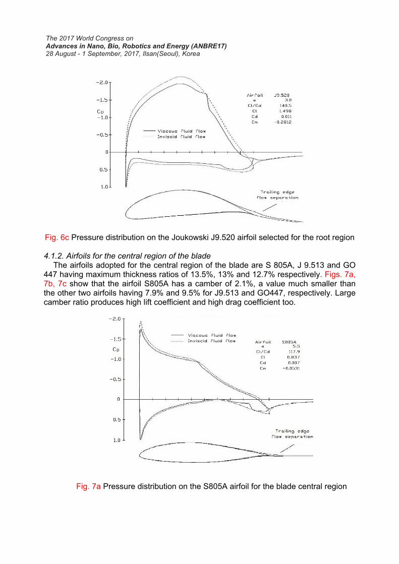
Fig. 6c Pressure distribution on the Joukowski J9.520 airfoil selected for the root region
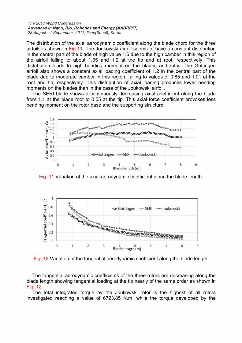
4.1.2. Airfoils for the central region of the blade The airfoils adopted for the central region of the blade are S 805A, J 9.513 and GO 447 having maximum thickness ratios of 13.5%, 13% and 12.7% respectively. Figs. 7a, 7b, 7c show that the airfoil S805A has a camber of 2.1%, a value much smaller than the other two airfoils having 7.9% and 9.5% for J9.513 and GO447, respectively. Large camber ratio produces high lift coefficient and high drag coefficient too.
Fig. 7a Pressure distribution on the S805A airfoil for the blade central region

The airfoil S805A shown in Fig. 7a has a maximum thickness of 13% and ratio of lift to drag coefficients of 117.13 and coefficients of drag and lift of0.00743 and 0.8698, respectively, at angle of attack of 5.5o. These values, as will be seen, are smaller than those for the other two airfoils. The GO 447 airfoil, Fig. 7b shows a similar pressure distribution as that of GO225 airfoil adopted for the root of the blade. The value of the ratio of lift to drag coefficients is about 153.78 or 23.9% higher than that of S807 occurring at angle of attack of 4.1°. The corresponding drag and lift coefficients for this angle are 0.00805 and 1.2381, respectively, are bigger than that of S807 but lower than that of J9.513. Fig. 7c shows the aerodynamic pressure distribution of the airfoil J9.513. It has maximum camber at nearly 50% of the chord and nearly constant pressure distribution on both sides of the airfoil. The ratio of lift to drag coefficient showed a maximum value of 185.64 at an angle of attack of 3.9o, which is 37% more than that of the S805A airfoil. The corresponding lift and drag coefficients at this angle are 1.6096 and 0.00867, respectively and both are higher than the values for the other two profiles of the central region.
Fig. 7b Pressure distribution on the GO447 airfoil for the blade central region
4.1.3. Blade tip airfoils The airfoils investigated for the blade tip are S806A, GO500 and J0910 and are shown in Figs. 8a, 8b, 8c. The airfoil S806A has a maximum thickness ratio of 11% while the other two have a maximum thickness ratio of 10% each. As a result S806A airfoil is heavier. The airfoil S806A shows small camber ratio, produces less lift at the tip and consequently sheds less tip vortices. On the other hand the airfoil Joukowski shows bigger camber ratio with the possibility of shedding more tip vortices producing higher local induced drag.

Fig. 7c Pressure distribution on the J9.513 airfoil for the blade central region
Fig. 8a Pressure distribution on the S806A airfoil selected for the blade tip region
The pressure distribution of the S806A airfoil, Fig. 8a is relatively high at the leading edge region and extends at lower values down to 50% of the chord. This distribution of pressure produces a maximum value of dCC / of about 108.37 occurring at angle of
attack of 3.2o and a corresponding lift and drag coefficients of 0.5708 and 0.00527,

respectively. These values are smaller than the corresponding values for the other two profiles as will be shown below.
The pressure distribution for airfoil GO500 is shown in Fig. 8b. The small camber reduces the turbulent effects near the trailing edge. The angle of attack for maximum ratio of lift to drag occurs at 2.6o for which the drag and lift coefficients are 0.00574 and 1.0116, respectively, while the maximum ratio of the lift to drag coefficients is 176.11.
The pressure distribution around airfoil J0910, Fig. 8c, shows maximum lift to drag ratio of 201.7 at an angle of attack of 2o. The corresponding lift coefficient is 1.33 or nearly 30% more than that of airfoil S806A. This permits using a smaller chord and less weight at the tip. The drag coefficient is found to be 0.00661 more than the other two tip profiles.
Fig. 8b Pressure distribution on the GO500 airfoil selected for the blade tip region

Fig. 8c Pressure distribution on the J0910 airfoil selected for the blade tip region
4.2. Rotor analysis based on the investigated airfoils
The three investigated airfoils families are used to design three wind turbines rotors of 50 kW nominal power for the working conditions listed in Table 2. Fig. 9 shows the variation of blade angle along the blade length for the three airfoil families Göttingen, SERI and Joukowski. The Göttingen airfoil shows a relatively bigger blade angle than the SERI airfoil but lower than that of the Joukowski airfoil. Small blade angle helps keeping the flow in contact with the blade surface at the leading edge and hence better aerodynamic performance of the blade.
Fig. 9 Distribution of the blade angle along the blade length.
The local aerodynamic chord of the each of the investigated airfoils is calculated along the blade length as shown in Fig. 10. One can observe that the root chord length of the Göttingen airfoil is 1.24 m and its chord length at tip is 0.3 m. In the case of SERI profile the tip chord length is 0.54 m much bigger than that of the Göttingen airfoil and consequently results in a heavier rotor. The local blade chord in the case of the Joukowski airfoil decreases gradually from 0.95 m at the root to 0.23 m at the tip. The local abrupt variations along the curves are due to numerical interpolation of airfoil data.
Fig. 10 Chord distribution along the blade length for the three airfoils families.
The distribution of the axial aerodynamic coefficient along the blade chord for the three airfoils is shown in Fig.11. The Joukowski airfoil seems to have a constant distribution in the central part of the blade of high value 1.6 due to the high camber in this region of the airfoil falling to about 1.35 and 1.2 at the tip and at root, respectively. This distribution leads to high bending moment on the blades and rotor. The Göttingen airfoil also shows a constant axial loading coefficient of 1.2 in the central part of the blade due to moderate camber in this region, falling to values of 0.85 and 1.01 at the root and tip, respectively. This distribution of axial loading produces lower bending moments on the blades than in the case of the Joukowski airfoil. The SERI blade shows a continuously decreasing axial coefficient along the blade from 1.1 at the blade root to 0.55 at the tip. This axial force coefficient provokes less bending moment on the rotor base and the supporting structure.
Fig. 11 Variation of the axial aerodynamic coefficient along the blade length.
Fig. 12 Variation of the tangential aerodynamic coefficient along the blade length.
The tangential aerodynamic coefficients of the three rotors are decreasing along the blade length showing tangential loading at the tip nearly of the same order as shown in Fig. 12. The total integrated torque by the Joukowski rotor is the highest of all rotors investigated reaching a value of 6723.85 N.m, while the torque developed by the
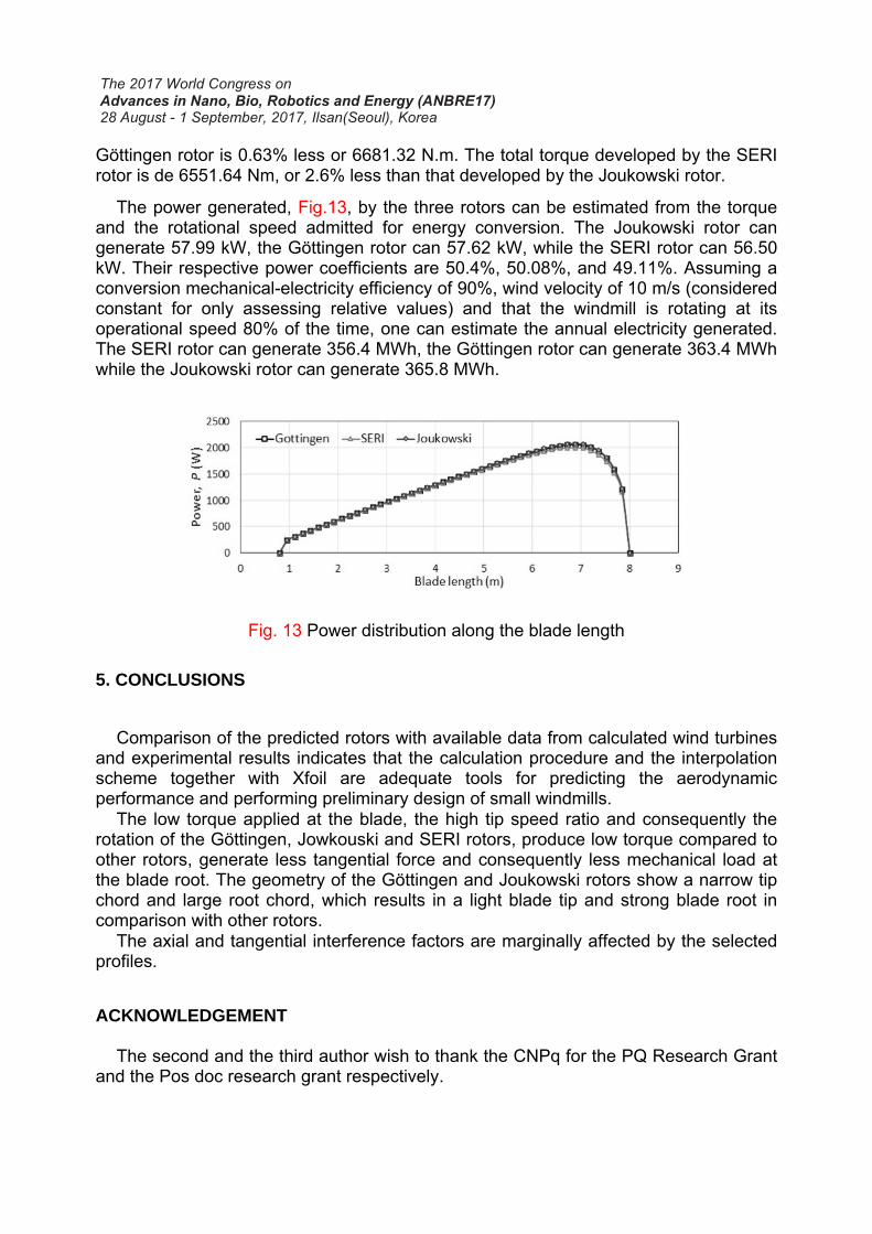
Göttingen rotor is 0.63% less or 6681.32 N.m. The total torque developed by the SERI rotor is de 6551.64 Nm, or 2.6% less than that developed by the Joukowski rotor.
The power generated, Fig.13, by the three rotors can be estimated from the torque and the rotational speed admitted for energy conversion. The Joukowski rotor can generate 57.99 kW, the Göttingen rotor can 57.62 kW, while the SERI rotor can 56.50 kW. Their respective power coefficients are 50.4%, 50.08%, and 49.11%. Assuming a conversion mechanical-electricity efficiency of 90%, wind velocity of 10 m/s (considered constant for only assessing relative values) and that the windmill is rotating at its operational speed 80% of the time, one can estimate the annual electricity generated. The SERI rotor can generate 356.4 MWh, the Göttingen rotor can generate 363.4 MWh while the Joukowski rotor can generate 365.8 MWh.
Fig. 13 Power distribution along the blade length
5. CONCLUSIONS
Comparison of the predicted rotors with available data from calculated wind turbines and experimental results indicates that the calculation procedure and the interpolation scheme together with Xfoil are adequate tools for predicting the aerodynamic performance and performing preliminary design of small windmills. The low torque applied at the blade, the high tip speed ratio and consequently the rotation of the Göttingen, Jowkouski and SERI rotors, produce low torque compared to other rotors, generate less tangential force and consequently less mechanical load at the blade root. The geometry of the Göttingen and Joukowski rotors show a narrow tip chord and large root chord, which results in a light blade tip and strong blade root in comparison with other rotors. The axial and tangential interference factors are marginally affected by the selected profiles.
ACKNOWLEDGEMENT The second and the third author wish to thank the CNPq for the PQ Research Grant and the Pos doc research grant respectively.

REFERENCES
Ajao, K.R., Adegun, I.K.(2009),“Development and power performance test of a small three-blade horizontal-axis wind turbine”, Heat Transf. Res.,40, 777-792.
Clifton-Smith, M.J., Wood, D.H.(2007),“Further dual purpose evolutionary optimization of small wind turbine blades”, J. of Physics, Conf. Series. IOP Pub., 12-17.
Giguere, P., Selig, M.S.(1998),“New airfoils for small horizontal axis wind turbines”, J. of Sol. Energy Eng.,120, 108-114.
Gu, R., Xu, J.L., Yang, Y.B.(2012),“The investigation of the small bionic wind turbine based on the seagull airfoil”,Adv. Mat. Res., Trans Tech Publications., 3533-3539.
Hassanzadeh, A., Hassanabad, A.H., Dadvand, A.(2016),“Aerodynamic shape optimization and analysis of small wind turbine blades employing the Viterna approach for post-stall region”, Alexandria Eng. J.,55, 2035-2043.
IEA (2003),“Energy balances of non-OECD Countries 2000-2001”, IEA /OECD, Paris. IEA (2007),“Key world energy statistics”, Inter. Energy Ag. Johansen, J., Madsen, H.A.,Gaunaa, M., Bak, C., Sørensen, N.N. (2009),“Design of a
wind turbine rotor for maximum aerodynamic efficiency”, Wind Energy,12, 261-273. Kanya, B., Visser, K.(2010),“The Impact of Airfoil Selection on the Design of Small
Horizontal Axis Wind Turbines”, 48th AIAA Aerospace Sci. Meet. Including the New Horizons Forum and Aerospace Exp., USA, p. 1583.
Karthikeyan, N., Murugavel K.K., Kumar, S.A., Rajakumar, S.(2015),“Review of aerodynamic developments on small horizontal axis wind turbine blade”. Renew.Sust. Energy Rev.,42, 801-822.
Manwell J.F., McGowan, J.G., Rogers, A.L. (2009),“Wind Energy Explained – Theory, Design and Application”, John Wiley & Sons Ltd.
Pourrajabian, A., Mirzaei, M., Ebrahimi, R. Wood, D. (2014). Effect of air density on the performance of a small wind turbine blade: A case study in Iran”, J. of Wind Eng. and Ind. Aerodynamics,126, 1-10.
Refan, M., Hangan, H.(2012),“Aerodynamic performance of a small horizontal axis wind turbine”, J. of Sol. Energ. Eng.,134, 021-013.
Selig, M.S., Mc Granahan, B. (2004),“Wind tunnel aerodynamic tests of six airfoils for use on small wind turbines”, 42nd Aerospace Sci. Meet.AIAA,USA.
Shen, X., Yang, H., Chen, J., Zhu, X., Du, Z. (2016),“Aerodynamic shape optimization of non-straight small wind turbine blades”. Energ. Conv. and Manag.,119, 266–278.
Singh, R.K., Ahmed, M.R., Zullah, M.A., Lee, Y-H.(2012),“Design of a low Reynolds number airfoil for small horizontal axis wind turbines”, Renew.Energ,42, 66-76.
Timmer, W.A., Rooij, R.V.(2003),“Summary of the Delft University wind turbine dedicated airfoils”, Wind Energy Symposium, American Soc. of Mec. Eng.,ASME pp.11-21.
UNDP (2004),“World energy assessment: overview”, World Energy Council update. Bureau for develop.Pol., New York, pp. 25-31.
Wood, D. (2011),“Small wind turbines, Analysis, design and application”, Springer-Verlag London, Limited.
Wright, A.K., Wood, D.H. (2004),“The starting and low wind speed behavior of a small horizontal axis wind turbine”, J. of Wind Eng. and Ind. Aerodynamics,92, 1265-1279.