thermophysical analysis of high modulus composite for satellite
TRANSCRIPT

Thermophysical Analysis of High Modulus Composite for Satellite Structure
Ho-Sung Lee 1), Kyung-Ju Min 2)
1) Department of Structures & Materials, [email protected] 2) Space Center , [email protected]
Korea Aerospace Research Institute, 45 Eoeun-Dong, Yuseong-Gu, Daejeon, 305-333, Korea
Abstract This paper discusses thermophysical analysis performed during development of a high modulus composite materi-
als for satellite structure. Materials properties required by satellite structure differ from those by aircraft applications. The
major difference includes high stiffness, low coefficient of thermal expansion, and dimensional stability in space environ-
ment. Therefore, thermophysical behavior of the material is very important. The composite specimens were composed of
YS90A carbon fiber and DGEBA(Diglycidyl Ether of Bisphenol A) resin for high temperature application. For comparison,
T300/epoxy composite specimen was also prepared in a form of tape and fabric with the same process. These materials
were characterized by measuring resin content, volatile content, gel time, DMA, TGA, and DSC. Thermal expansion and
conductivity properties were also measured. Mechanical properties were also measured at three different temperatures and
the thermal cycling test was performed. This study has showed that high modulus composites offer potential in the use of
satellite application.
Key Words : High Modulus Composite, Thermophysical Analysis, Pitch-based Carbon, Satellite, Heat Pipe Panel
1. Introduction
Polymer matrix composite materials have been among the most widely used materials for aerospace over the past 20
years. These materials usually consist of reinforced filamentary phases embedded in a continuous matrix. The property of
a composite material depends on the combination of matrix and reinforcement. Typical reinforcements are fiberglass, car-
bon, and aramid fibers. These composite materials have been successfully demonstrated their superior properties to conven-
tional metallic systems in secondary and primary parts in aircraft structures. These properties are higher specific
strength(strength-to-density ratio), corrosion resistance, design flexibility, reducing number of assemblies and fasteners,
and high resistance to fatigue damage. In composite system, depending on the orientation of fibers, strength and stiffness
can be changed so that the optimum structure can be accomplished. Depending on treatment, some of composite materials
absorb radar microwaves. In addition, carbon fiber composite materials can show the coefficient of thermal expan-
sion(CTE) close to zero. This is because the CTE of highly aligned carbon fibers between 0 and 500℃ is negative. Carbon
fiber polymer-matrix composites become important in space technology because the fibers serve to reduce the CTE, in-
crease the strength and modulus, and decrease the density. For spacecraft electronics and orbiting space structure, which
are thermally cycled by moving through the earth' shadow, these materials become one of the best selections.
Generally most of polymer matrices exhibit relatively poor thermal conductivity, the composite materials have been
widely considered only for structural application and little for thermal application. However, recently relatively graphitic
kind of carbon fiber becomes available and this fiber shows high thermal conductivity. Because of this combination of low
CTE and high thermal conductivity, continuous carbon fiber composites make them suitable for thermal management like
heat sinks in electronics. Since a heat sink is in contact with a ceramic chip carrier or a printed circuit board, a low thermal
expansion is preferred. The high thermal conductivity of the composites makes them even more attractive for aerospace
electronics.
This objective of this paper is to describes the work performed in a program which demonstrates that advanced com-
posite heat panel of communication satellite(Figure-1) can be designed and demonstrated to satisfy thermal requirement of
the panel. The panel must support the equipment weight during launch and also be able to effectively dissipate excess
heat from equipment while on orbit. Therefore, the material must satisfy the various requirements including functional and
space environmental condition(Table-1). In this paper, only the results from the thermal conductivity study are presented.
A pitch-based carbon fiber was used to develop the composite material, which thermal conductivity was higher than alumi-
num alloys. The results include comparison between theoretical analysis[1,2] and experimental results for thermal con-
ductivity of this advanced composite material. It was demonstrated also that the fabric composite material with conductive
filler could meet the transverse thermal conductivity requirement.
2. Experimental Figure-2 shows the layout of the electronic devices and heat pipe arrangement of the panel. Each electronic device
produces about 10 to 100 W. The facesheet was originally made of an aluminum alloy. This facesheet is about to be re-
placed with proposed composite material. The cross-sectional view of this panel is shown in Figure-3. The composite pre-
preg material were composed of a pitch-based carbon fiber with 6,000 fibers per tow and an epoxy resin of
DGEBA(diglycidyl ether of bisphenol A) based curable at 163 . The ℃ carbon fiber is a continuous high modulus(880
GPa), pitch based fiber. For the purpose of comparison, the conventional PAN (polyacrylonitrile)-based carbon fiber com-
posite specimen was also prepared in a form of tape and fabric with the same fabrication process. These materials were
characterized by measuring resin content, volatile content, gel time, DMA(Dynamic Mechanical Analysis), TMA(Thermo-
Mechanical Analysis), and DSC(Differential Scanning Calorimetry).
Longitudinal thermal conductivity was measured from specimens of 20cm long by 1.0cm wide with 0.008mm diame-
ter(AWG40) K-type thermocouples. A power supplier was used to supply the power of 0.2W to 5W to resistance heater
which was attached to one end of the specimen. The temperature difference was monitored with 3 thermocouples which
were placed on the center of the specimen over a distance of 10cm. The specimen was wrapped with several layers of ce-
ramic wool for complete insulation during measurement. It took about an hour for the temperatures of thermocouple read-
ing to reach equilibrium at a given power. The temperatures were monitored and the thermal gradient across the specimen
was used to determine the thermal conductivity.
Thermal conductivity in thickness direction of composite was measured between two copper blocks. The resistance
heater, of 0.3mm in thickness and 157 Ohm, was placed in the middle of two specimens and symmetry was obtained. The
conductivity through the specimen of 25mm square was calculated from the temperature gradient across the specimen stack,
the power input and specimen geometry. Since the main role of composite face sheet of the heat pipe panel is to transfer
the heat from equipments to pipe, the conductivity of thickness direction is one of the utmost concerns. However, all poly-

mer materials are poor thermal conductors and it is necessary to improve the thermal conductivity in the thickness direction.
In this study, BN(Boron Nitride) and AlN(Aluminum Nitride) were studied for possible application as fillers in resin matrix.
These conductive ceramic powders are preferred over metallic powders, for the latter may induce corrosion with epoxy ma-
trix over time[3]. The average particle size was about 10 microns for both BN and AlN powders.
3. Results and Discussion
To obtain the glass-rubber transition temperature (Tg) of this composite material, two different methods were applied
and compared. Firstly, the dynamic mechanical behaviors were measured with the DMA (Dynamic Mechanical Analyzer)
which shows the change in the modulus of the sample with temperature as shown in Figure 4. The quantity E', Young's stor-
age modulus, is a measure of the energy stored elastically, whereas E", Young's loss modulus, is a measure of the energy
lost as heat. The quantity tan δ is calculated by E"/E' and called the loss tangent, δ being the angle between the in-phase
and out-of-phase components in the cycle motion. The maximum in tan δ is used as the definition of Tg. Thus, it was un-
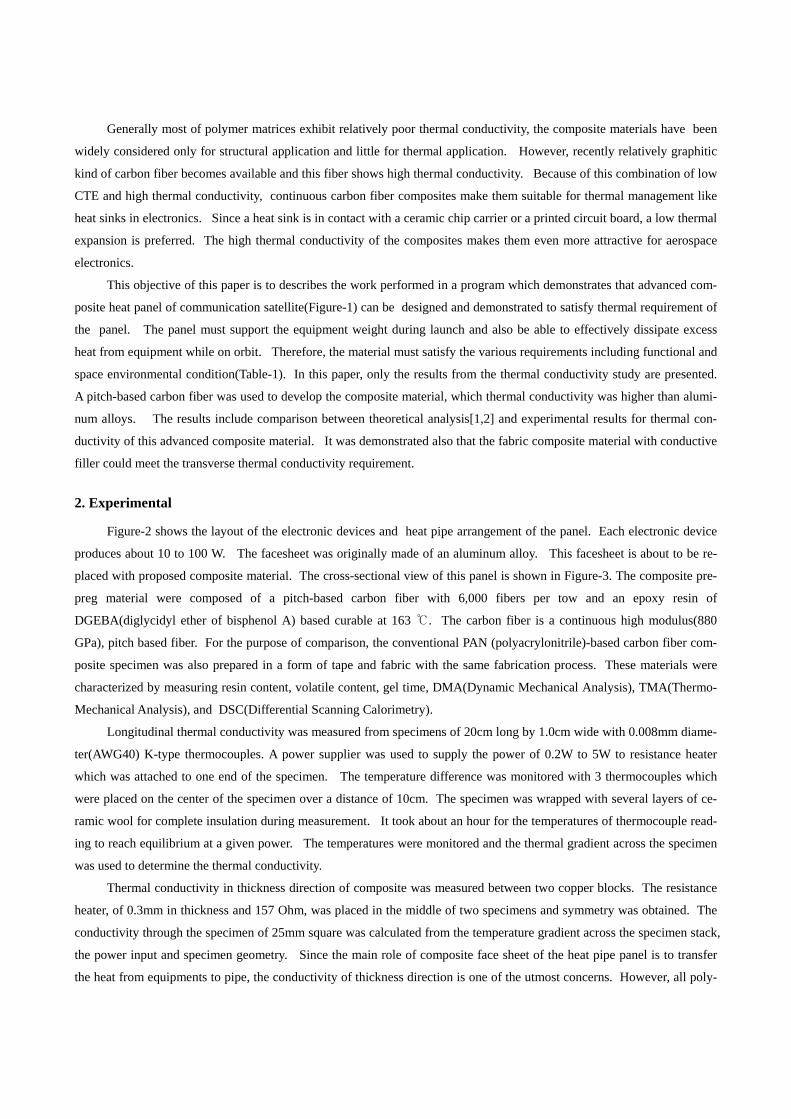
derstood that the Tg of the system is 225.2 ℃. Secondly, the temperature at which one-half of the change in heat capacity
was measured using DSC (Differential Scanning Calorimetry) in which the heating rate was 10 ℃/min and was taken as Tg
as shown in Figure 5. Tg of the system obtained from the DSC is about 20 ℃ lower than obtained from DMA. This result
might be attributed to the different testing methods between dynamic and static response in molecular motion.
The coefficients of thermal expansion(CTE) of the composite system were measured using TMA(Themal Mechanical
Analyzer) at two different textures, parallel and perpendicular to the fiber axis and the result of fiber direction is shown in
Figure 6. As might be expected, the CTE of the sample with perpendicular to the fiber axis is positive since the CTE of ma-
trix could dominate in this direction. On the other hand, the CTE of the sample with parallel to the fiber axis is negative,
which is a similar trend of the CTE of the fiber, since the fiber could dominate in this direction.
The viscosity of matrix is important for complete wetting of resin to fiber. The results of viscosity measurements
with filler loadings from 5 to 20% are shown in Table 2. It is interesting to note that the viscosity does not change very
much with increasing the amount of AlN.
In Figure 7, experimental data are compared with values predicted by Hasselman and Nielsen[4,5]. It indicates a general
trend of increased thermal conductivity with filler loading. Specimens with AlN show reasonably good agreement with
both models even though the experimental values are slightly higher than the theoretical values. However, adding BN in-
creases the conductivity much higher than the predicted values. By observing the shape of particles, it was shown that BN
particles had relatively irregular shape while AlN particles were spherical. From Figure 5, it is clear that BN performs bet-
ter thermal conductivity than AlN does in this matrix. Therefore, BN was selected and the maximum loading of 20% was
chosen because after this value, the viscosity would be too high to obtain complete implantation with resin.
The results of the thermal conductivity tests are given in Table 3. It is shown that the pitch-based carbon fiber
composite performed the best and for Kx, this composite exhibits thermal conductivity value even higher than that of alu-
minum alloys. There are more effects of adding BN conductive filler on the transverse thermal conductivity than the longi-
tudinal thermal conductivity. The transverse thermal conductivity of a fabric composite was enhanced by 66% with 20%
of BN. It is notable that the thermal conductivity value of 0.75W/m-K of the PAN-based carbon fiber composite exceeds
the design requirement for the transverse thermal conductivity, which is 0.6W/m-K.

Based on these results, by using composite materials replacing an aluminum alloy in the facesheet, it is possible to
reduce the weight by 1.27Kg. In addition to this, the higher thermal conductivity makes it possible that the height of heat
pipe could be decreased so that the total saving of reduced heat pipe is 0.59Kg. Overall weight saving is expected about
14% by using this high conductivity composite material.
4. Conclusion
It is shown that significant increase of thermal conductivity in thickness direction of composite was observed
with the addition of BN conductive fillers in the composite matrix up to 20%. l. The transverse thermal conductivities
as high as 0.75W/m-K were obtained for a PAN-based carbon fiber composite fabric with 20% of BN. This value is
higher than design requirements for heat pipe panel. High thermal conductivity of 239 W/m-K in longitudinal direction
and 1.32 W/m-K in transverse direction, was achieved with a pitch-based carbon composite materials. These values are
sufficient to satisfy the design requirements for the facesheet of heat pipe panel. Replacing an aluminum alloy in the
facesheet with a high conductivity composite material, it is demonstrated that the composite material offers potential in
the thermal and structural application of spacecraft heat pipe panel.
References
[1] S. Torquato., Rev. in Chem. Eng., 4: 151-204(1987).
[2] R.C. Progelhof., J.L. Throne, and R.R Reutsch., Polymer Engineering and Science, 16: 615-625.(1976)
[3] Peterson, G.P. and Fletcher, L.S., AIAA-87-1586, June(1987).
[4] L.E. Nielsen, J. of Applied Polymer Science, 17: 3819-3820(1973).
[5] D.P.H.Hasselman and L.F. Johnson, J. of Composite Materials, 21: 508-515(1973).
Figure – 1 Schematic configuration of communication satellite and electronic device panel

Figure – 2 Heat pipe layout of an electronic device panel
Figure – 3 Cross-section of a composite panel
Figure – 4 DMA curve of a pitch-based carbon fiber composite panel
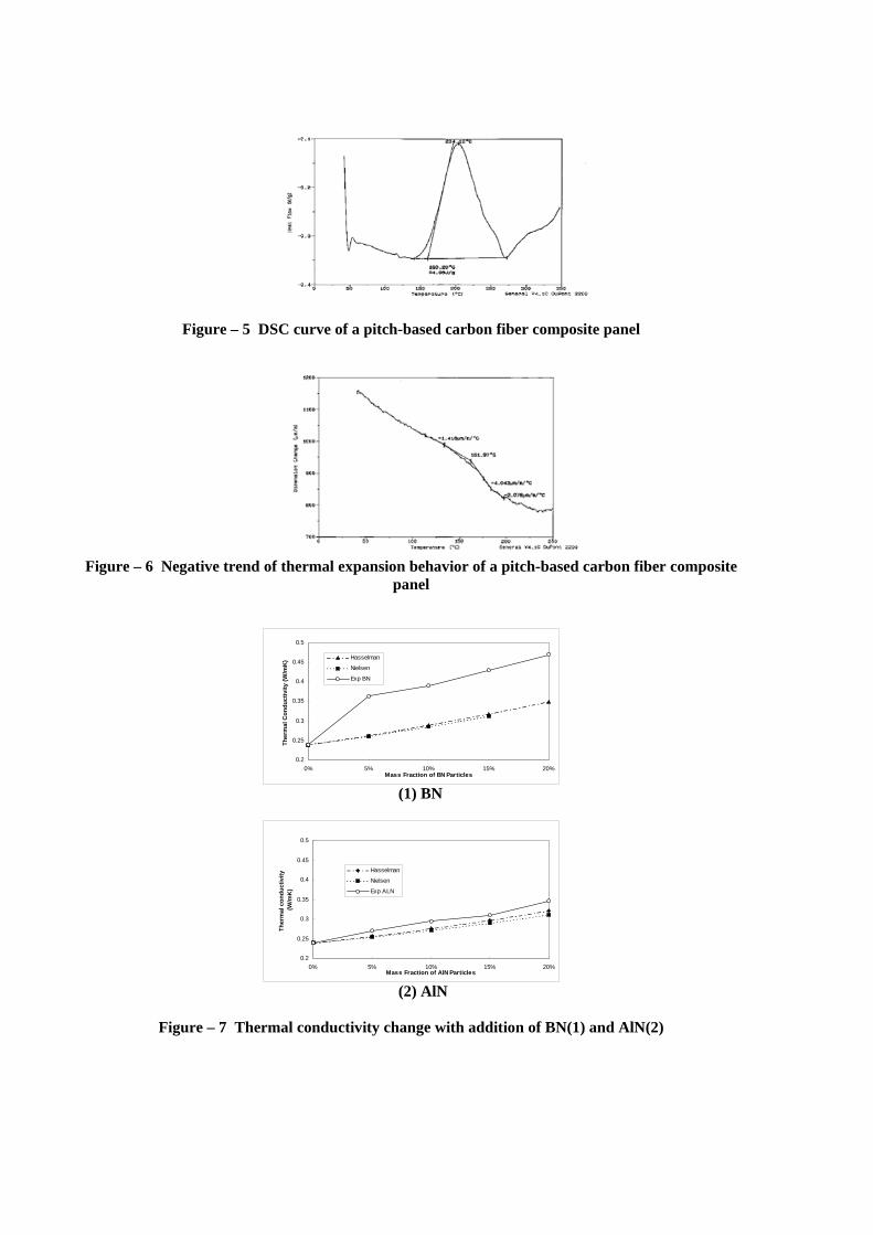
Figure – 5 DSC curve of a pitch-based carbon fiber composite panel
Figure – 6 Negative trend of thermal expansion behavior of a pitch-based carbon fiber composite
panel
0.2
0.25
0.3
0.35
0.4
0.45
0.5
0% 5% 10% 15% 20%Mass Fraction of BN Particles
Ther
mal
Con
duct
ivity
(W/m
K) Hasselman
Nielsen
Exp BN
(1) BN
0.2
0.25
0.3
0.35
0.4
0.45
0.5
0% 5% 10% 15% 20%Mass Fraction of AlN Particles
Ther
mal
con
duct
ivity
(W/m
K)
Hasselman
Nielsen
Exp ALN
(2) AlN
Figure – 7 Thermal conductivity change with addition of BN(1) and AlN(2)

Table-1 System requirements for a face sheet of heat pipe panel
Parameters Minimun Values - Operating Temperature 50 ~ + 80 ℃ ℃ - Outgassing < 1.0% TML
< 0.1% VCML - Thermal Conductivity (thickness) > 0.6 W/m․K
- Tensile Strength > 400 MPa - Shear Strength > 200 MPa - Tensile Modulus > 72 GPa - Shear Modulus > 35 GPa - Coefficient of Thermal Ex-pansion 22 x 10-6/K
- Density 1.6 g/cc
Table-2 Viscosity change with addition of filler (unit: cps)
Wt % Filler 0 % 5 % 10 % 15 % 20 %
BN 5,300 7,500 10,000 12,400AlN 5,050 3,600 4,000 3,800 4,000
Table-3 Thermal conductivities of various specimens (unit: W/m-K)
PAN-based Carbon Composite
PAN-based Carbon Fabric Composite
PAN-based Carbon Fabric Composite
with BN20%
Pitch-based Carbon Composite
kx 5 2 2.9 239
kz 0.27 0.45 0.75 1.32