thermone - alt-aqua.com
TRANSCRIPT

61236 PEX CONNECTION
• PEX water inlets and top outlet / Entrées d'eau et sortie d'eau du haut PEX• 1/2" male bottom water-outlet - NPT/sweat / Sortie d’eau du bas 1/2" mâle - NPT/soudé
61238 WB CONNECTION
• WB water inlets and top outlet / Sortie d’eau du bas 1/2" mâle - NPT/soudé• 1/2" male bottom water-outlet - NPT/sweat / Sortie d’eau du bas 1/2" mâle - NPT/soudé
61234 NPT CONNECTION
• 1/2" male water inlets - NPT/sweat / Entrées d’eau 1/2" mâle - NPT/soudé• 1/2" male water outlets - NPT/sweat / Sorties d’eau 1/2" mâle - NPT/soudé
ThermOne61234 / 61236 / 61238
NPT/sweat connection / Pex connection / WB connectionConnexion NPT/sweat / connexion Pex / connexion WB
Project Divison Projet

last revision: 04/06/2021
Project Divison Projet
2
CONGRATULATIONSFÉLICITATIONS
Congratulations on the purchase of your Aquabrass product
By purchasing an Aquabrass/Alt product, you are taking part in the global movement for bet-ter living. We take pride in manufacturing drinking water faucets that are certified Lead-Free. Also, nearly all of our faucets exceed industry standards in water conservation. We’ve equipped them with efficient ecological aerators that reduce water consumption without giving up perfor-mance. Let’s protect our most precious natural resource for generations to come. We recommend the installation of this product to be done by a licensed plumber. Please take a moment to read the following instructions and keep this document for future reference. We hope this product will provide you with many years of trouble-free enjoyment. Should you require any technical or warranty assistance, please visit us at:
www.aquabrass.comwww.alt-aqua.com
Félicitations pour l’achat de votre produit Aquabrass
En achetant un produit Aquabrass/Alt, vous prenez part au mouvement global pour le mieux-vivre. Nous sommes fiers de fabriquer des robi-nets d’eau potable qui sont tous certifiés Sans Plomb. De plus, la plupart de nos robinets surpassent les normes de l’industrie en matière de préservation d’eau. Ils sont tous dotés d’aérateurs écologiques qui réduisent la consommation d’eau sans perte de performance. Veillons à cette ressource naturelle pour nos générations futures.
Nous recommandons l’installation de ce produit par un plombier accrédité. SVP prendre le temps de bien lire ce manuel d’installation avant de déb-uter. Garder ce manuel en référence pour usage futur. Nous espérons que ce produit vous procurera des années d’agréable usage. Pour tout soutien tech-nique ou bien pour des questions sur la garantie, SVP visitez notre site au :
www.aquabrass.comwww.alt-aqua.com

last revision: 04/06/2021
Project Divison Projet
3
SPECS AT LARGE / SCHÉMA DES PIÈCES
1 ALT760705SS: check valve/ valve d'arrêt2 ABSP61200: 1/2' NPT Diverter plug / Bouchon du déviateur 1/2' NPT3 ABSP61201: Adaptor / Extension for ThermOn ABHS62088PC e / Adaptateur / Extension pour ThermOne4 ABSP61202: Rubber gaskets / Joints en caoutchouc5 ABSP61203: Legs extension / Extensions 6 ABSP61200: Spacer / Espaceur7 ALT760703: Cartridge holder / Manchon de cartouche8 ALT760706 : Rubber gaskets / Joints en caoutchouc9 ALT76010100 : Extension kit (sold separately) / Kit d'extention (vendu séparément)
VALVE COMPONENTSCOMPOSANTES DE LA VALVE
7
6
5
4
2
31
8
Extension kit / Kit d'extention
9
see pag 11 / Voir pag 11

last revision: 04/06/2021
Project Divison Projet
4
[47.83]1 7/8”
1/2” PEX
[85.00]3 3/8”
[43.84]1 3/4”
[141.80]5 9/16”
1/2” PEX
[35.10]1 3/8”
[48.00]1 7/8”
Min 2 1/8”Max 3 1/16”
SHOWER/DOUCHE
HOT WATEREAU CHAUDE
COLD WATEREAU FROIDE
TUB/BAIN
GENERAL DIMENSIONS DIMENSIONS GÉNÉRALES
BEFORE YOU STARTAVANT DE COMMENCER
CAUTION: FOR BEST RESULTS, WE STRONGLY RECOMMEND THE INSTALLA-TION OF THIS VALVE BE DONE BY A LICENSED PLUMBER.
CAUTION: MAKE SURE TO PROPERLY FLUSH THE HOT AND COLD WATER SUP-PLY. FAILURE TO CARRY OUT THIS SIMPLE PROCEDURE COULD CAUSE PROBLEMS OR DAMAGE TO THE WORKING OF THE FAUCET.
MISE EN GARDE: POUR OBTENIR UN RÉ-SULTAT OPTIMAL, NOUS RECOMMANDONS FORTEMENT QUE L’INSTALLATION DE CETTE VALVE SOIT FAITE PAR UN PLOMBIER AC-CRÉDITÉ.
MISE EN GARDE: ASSUREZ-VOUS DE BIEN PURGER L’ALIMENTATION D’EAU CHAUDE & FROIDE. NE PAS FAIRE CETTE ETAPE POURRAIT CREER DES PROB-LEMES OU DOMMAGES POUR LE FONC-TIONNEMENT DU ROBINET.
last revision: 04/06/2021
Project Divison Projet
5
1.
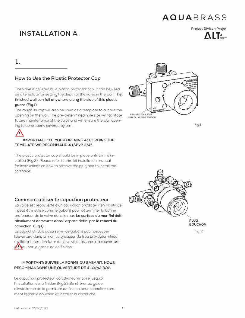
How to Use the Plastic Protector Cap
The valve is covered by a plastic protector cap. It can be used as a template for setting the depth of the valve in the wall. The finished wall can fall anywhere along the side of this plastic guard (Fig.1).The rough-in cap will also be used as a template to cut out the opening on the wall. The pre-determined hole size will facilitate future maintenance of the valve and will ensure the wall open-ing to be properly covered by trim. IMPORTANT: CUT YOUR OPENING ACCORDING THE TEMPLATE WE RECOMMAND 4 1/4"x2 3/4".
The plastic protector cap should be in place until trim is in-stalled (Fig.2). Please refer to trim kit installation manual for instructions on how to remove the plug and to install the cartridge .
Comment utiliser le capuchon protecteurLa valve est recouverte d'un capuchon protecteur en plastique. Il peut être utilisé comme gabarit pour déterminer la bonne profondeur de la valve dans le mur. La surface du mur fini doit absolument demeurer dans l'espace défini par le rebord du capuchon (Fig.1). Le capuchon doit aussi servir de gabarit pour découper l'ouverture dans le mur. La grosseur du trou pré-déterminée facilitera l'entretien futur de la valve et assurera la couverture du trou par la garniture de finition.
IMPORTANT: SUIVRE LA FORME DU GABARIT. NOUS RECOMMANDONS UNE OUVERTURE DE 4 1/4"x2 3/4".
Le capuchon protecteur doit demeurer posé jusqu'à l'installation de la finition (Fig.2). Se référer au guide d'installation de la garniture de finition pour connaître com-ment retirer le bouchon et installer la cartouche.
FINISHED WALL STOP LIMITE DU MUR DE FINITION
INSTALLATION A
PLUGBOUCHON
Fig.1
Fig. 2

last revision: 04/06/2021
Project Divison Projet
6
2.
Installing the valve
Once the mixer location is determined, posi-
tion the valve in between 2x4 studs inside the
wall on a plywood backing for better support.
Make sure the valve is level and at the right depth
before securing it firmly in place.
Intallation de la valve
Une fois l'emplacement déterminé, position-
ner la valve entre 2 montants 2x4 dans le mur,
sur un support en contre-plaqué. S'assurer que
la valve soit à niveau et à la bonne profondeur
avant de la fixer fermement.
Fig.3
Max [78.00] 3 1/16”
VALVE
PLASTIC PROTECTORPROTECTEUR DE PLASTIQUE
WOOD SUPPORTSUPPORT EN BOIS
FINISHED WALLMUR DE FINITION
Min [54.00] 2 1/8”
INSTALLATION A

last revision: 04/06/2021
Project Divison Projet
7
INSTALLATION B (Thin wall)
1.
How to Use the Plastic Protector Cap in a thin wall (3/8" or less)
For this installation, you will need to also have the
selected trim components at hand.
The "Thin Wall" method is used when the tub/shower
wall is less than 3/8" thick and serves as the main source of support for the valve (such as an acrylic
tub surrounds).
Temporarily remove the plastic guard, remove the 4
white leg extensions and put aside the 2 screws.
Cut away the central portion of the plastic cover.
(Fig. 4)
Cut a 3" opening into the finished shower wall
Comment utiliser la capuchon en plas-tique dans un mur 'fin'. Pour un mur dont l'epaisseur est égales ou inférieur à 3/8"
Pour cette installation vous avez besoin d'avoir les
composants de la finition.
La méthode pour "mur fin" est utilisé quand le
mur de la baignoire/douche fait moins de 3/8"
d'épaisseur et sert de support principal pour la fini-tion (comme par exemple les murs d'un bain/douche
en acrylique).
Temporairement, retirer le capuchon plastique. Re-
tirer les 4 extensions, mettre de côté les 2 vis. Con-
server les pour l'étape suivante.
Découper la partie centrale du capuchon en plas-
tique.(Vois fig 4)
Sur le mur de la douche, à l'emplacement du mélan-
geur , perforer une ouverture de 3".
1
Fig.4
REMOVE THE FOUR EXTENSIONS
RETIRER LES QUATRE EXTENSIONS
2
1
Min 1/8” - Max 3/8”
Recommended 3”
Fig.5

last revision: 04/06/2021
Project Divison Projet
8
less than [12.00] 1/2”
Recommended ø 3”
Fig.7
2.
Installing the cartridgeUnscrew the cartridge holder (1) and remove the protective
plug. Fig. 6. Make sure the "top" plastic spacer remains in
place (3).
Insert the cartridge (2) into the valve body as shown. Fig.6.
Make sure its guiding lugs line-up with the corresponding
openings in the rough. Push the cartridge until its suround-
ing O-ring is firmly engaged. Reinstall the cartridge holder
(1). DO NOT OVERTIGHTEN.
Installing the roughPosition the rough with the plastic cover surface firmly
against the back of the wall.
Complete the installation by tightly grabbing the thin wall
between the mixer rough and the circular adaptor. Fig. 7.
Screw in place using the top left and bottom right positions.
Fig 5.
Installation de la cartoucheDévisser le manchon de la valve (1) et retirer le capuchon
protecteur. Fig. 6. Assurez-vous de ne pas perdre l'anneau
en plastique monté sur le dessus (3).
Insérer la cartouche (2) dans la valve telle qu'illustré. Fig. 6
Utiliser les 2 projections en dessous comme guide pour
l'orienter correctement. Enfoncer la cartouche, jusqu'à ce
que le joint thorique du pourtour soit fermement engagé
dans la base. refermer la valve à l'aide du manchon. NE
PAS TROP SERRER.
Installation de la plomberie brutePositionner la plomberie brute avec son capuchon plas-
tique à l'arrière du mur.
Compléter l'installation en pinçant le mur fin entre la plom-
berie brute du mélangeur et l'adaptateur circulaire. Fig. 7.
Visser les composantes en utilisant les emplacements su-
périeur gauche et inférieur droit seulement. Fig 5.
2
13
Fig.6
INSTALLATION B (Thin wall)

last revision: 04/06/2021
Project Divison Projet
9
INSTALLATION A / B
3.
Connecting the Water
(A)
(B)
UP
DOWN
HOT WATEREAU CHAUDE
COLD WATEREAU FROIDE
TO TUB SPOUT WITH DIVERTERVERS LE BEC AVEC DÉVIATEUR
TO THE SHOWER HEADVERS LA TÊTE DE DOUCHE
Connect the hot and cold water inlets and the
mixed water outlets. Fig.8. The hot water must
always be connected on the left side and the
cold water on the right, as indicated on the valve
body. Ensure the piping is free of debris and dirt
to prevent blockage in the mixer.
This valve is fitted with 2 mixed water outlets (A
and B). Seal the (B) outlet if not used.
Once all water connections have been made,
check for possible leaks.
Raccordement de l'eau
Raccorder les entrées d'eau chaude et froide
ainsi que ceux pour la distribution d'eau mélan-
gée. Fig. 8. L'eau chaude doit toujours être rac-
cordée du côté gauche et l'eau froide du côté
droit, tel qu'indiqué sur la valve. S'assurer que la
tuyauterie ne soit pas encombrée avec des gra-
vats et des impuretées afin d'éviter l'obstruction
du mélangeur.
La valve possède 2 sorties d'eau (A et B) pour
l'eau mélangée. S'assurer de bien sceller la sortie
(B) si elle n'est pas utilisée.
Une fois tous les raccordements terminés, vérifier
pour des fuites possibles.
Fig.8
last revision: 04/06/2021
Project Divison Projet
10
MAINTENANCE
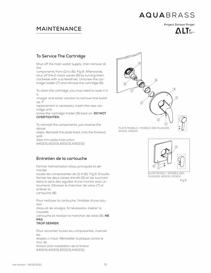
To Service The Cartridge
Shut off the main water supply, then remove all thecomponents from (1) to (6). Fig.9. Afterwards, shut off the 2 check valves (9) by turning them clockwise with a screwdriver. Unscrew the car-tridge holder (7) and remove the cartridge (8).
To clean the cartridge, you may need to soak it in avinegar and water solution to remove lime build-up. Ifreplacement is necessary, insert the new car-tridge andscrew the cartridge holder (9) back on. DO NOT OVERTIGHTEN.
To reinstall the components, just reverse the abovesteps. Reinstall the plate back onto the finished wall.(See trim plate instruction #40231,#10231,#20231,#30231)
Entretien de la cartouche
Fermer l'alimentation d'eau principale et dé-montertoutes les composantes de (1) à (6). Fig.9. Ensuite,fermer les deux valves d'arrêt (9) en les tournant dans le sens des aiguilles d'une montre avec un tournevis. Dévisser le manchon de valve (7) et enlever lacartouche (8).
Pour nettoyer la cartouche, l'imbiber d'une solu-tiond'eau et de vinaigre. Si nécessaire, insérer la nouvellecartouche et revisser le manchon de valve (9). NE PASTROP SERRER.
Pour remonter toutes les composantes, inverser lesétapes ci-haut. Réinstaller la plaque contre le mur definition.(Voir installation de la finition #40231,#10231,#20231,#30231)
42
1
3
8
9
7
5
6
4
3
2
1
PLATE MODEL / MODÈLE DES PLAQUES: #20231, #30231
PLATE MODELS / MODÈLE DES PLAQUES: #10231, #40231
Fig.9

last revision: 04/06/2021
Project Divison Projet
11
INSTALLATION EXTENSION KIT
Shut off the main water supply, then remove all the
components from (1) to (8) Fig. 10. Afterwards, dis-
card of the 2 screws (3).
Install the extension kit (1 & 2) and reinstall the
components (3 to 7) following the above steps in the
reverse order.
Reinstall the plate (8) using the new screws (9), back
onto the finished wall. Place the handle (10) and fix
with the set screw (11). Fig. 11
Entretien de la cartouche
Fermer l'alimentation d'eau principale et démonter
toutes les composantes de (1) à (8) Fig.10. Ensuite,
éliminer les deux vis (3).
Installer les kit d'extention (1 & 2) et réinstaller les
composants (3 à 7) dans l'ordre inversé à la fig. 10.
Réinstaller la plaque (8) utilisant les nouvelle vis (9),
contre le mur definition. Placer la poignée (10) et
fixer avec la vis de réglage (11). Fig. 11
2
1
4
3
56
7
8
1
23
5
67
8
9
11
10
4
* extension kit kit d’extention
*
*
2
1
4
3
56
7
8
1
23
5
67
8
9
11
10
4
* extension kit kit d’extention
*
*
Fig.10
Fig.11

last revision: 04/06/2021
Project Divison Projet
12
CARE SOIN
To clean your Aquabrass faucet or accessory, wash with a wet nonabrasive soapy cloth. Then wipe dry with a soft towel or cloth. We recommend this be done on a regular basis.
DO NOT USE ANY ABRASIVE, CHEMICAL OR CORROSIVE, POWDER OR ANY OTHER STRONG CLEANERS INCLUDING DETERGENTS, WINDOW CLEANERS AND DISINFECTANTS ON YOUR Aquabrass PRODUCT as they will destroy the fin-ish and therefore VOID THE WARRANTY.
Toothpaste remnants should also be rinsed off when necessary. Ask your plumbing retailer about our PROTECTANT-CLEANER now available from Aquabrass. This product is specially manufactured to clean and polish leaving a protec-tive coating to maintain your product’s shine and finish.
Pour nettoyer et conserver l’apparence de vos robinets ou accesoires Aquabrass, lavez-les avec un linge mouillé à l’eau tiède et enduit d’un savon doux non-abrasif. Puis essuyer avec un linge doux et sec. Nous vous recommandons cet entretien sur une base régulière.
NE JAMAIS UTILISER DE PRODUITS ABRASIFS, CHIMIQUES, CORROSIFS, INCLUANT DE TRÈS FORTS DÉTERGENTS, EN LIQUIDE OU EN POUDRE, NETTOYANTS POUR VITRES ET DÉSINFECTANTS sur votre produit Aquabrass. Cela pour-rait en détériorer le fini et ANNULER LA GARANTIE.
Les restants de pâte à dentifrice doivent aussi être rincés au besoin. Demander à votre détaillant le PROTECTEUR NETTOYANT Aquabrass spécialement conçu pour nettoyer, faire briller et protéger en laissant un mince film pro-tecteur sur vos robinets et vos articles décoratifs.

last revision: 04/06/2021
Project Divison Projet
13
Les produits Aquabrass ont une garantie complète contre les défauts de matériel et de main d’œuvre. La garantie est applicable seulement si le produit est acheté chez un détaillant Aquabrass dûment autorisé. La garantie Aquabrass est strictement limitée au premier acheteur et une preuve d’achat doit être présentée pour toutes réclamations. Les produits considérés comme défectueux doivent être retournés à nos entrepôts pour inspection avant tout remplacement.La garantie Aquabrass n’est pas transférable et est limitée aux produits vendus et installés au Canada et aux États-Unis.
Applications résidentielles
- toutes les parties mécaniques incluant les cartouches à disques en céramique pour les valves et les pressions équilibrées, les cartouches thermostatiques, les déviateurs ont une garantie complète au premier acheteur.
- les finis chrome poli et nickel brossé Aquabrass ont une garantie à vie limitée au premier acheteur. - tous les autres finis ont une garantie de cinq (5) ans (le nickel satiné naturel [#210] se patinera avec le temps), excepté le laiton brut (#400) qui est un fini
vivant pour lequel il n’y a pas de garantie.- l’usure normale d’un fini n’est pas couverte par la garantie.- toutes les composantes et les robinets électroniques ont une garantie de deux (2) ans.- toutes les vasques en verre, les lavabos en porcelaine ont une garantie de un (1) an. - les bains et lavabos en composite de pierre / résine ont une garantie de cinq (5) ans.- les collections de mobilier de salle de bain ont une garantie de un (1) an.- tous les autres produits ont une garantie de cinq (5) ans.
Applications commerciales et industrielles
Tous les produits ci-dessus sont garantis pour deux (2) ans à l’exception des vasques en verre ou en porcelaine qui sont garanties un (1) an.
La garantie Aquabrass ne couvre pas :
- dommages causés en entier ou en partie par une erreur d’installation, d’abus de produit, de négligence, d’utilisation non conforme, d’usage de produits abrasifs, de corrosion et/ou d’accidents causés par un professionnel ou par toute autre personne.
- tout produit Aquabrass nettoyé avec des produits abrasifs, comme les détergents ou les nettoyants à vitres.- usure normale du fini.- dommages causés par l’eau dure, les dépôts de calcaire ou les sédiments.- les dommages ou les pertes résultant d’une catastrophe naturelle telle qu’un feu, un tremblement de terre, le tonnerre, un orage électrique, etc.Aquabrass n’accepte aucune responsabilité pour tout frais de main d’œuvre ou d’expédition, ou pour tout autre dommage causé en totalité ou en partie lors de l’installation du produit, de son retrait, de sa réinstallation, de sa réparation, ou le remplacement de tout produit ou pièce Aquabrass, ainsi que tout dom-mage occasionnel ou conséquent, dépense, perte directe ou indirecte, provenant de quelque cause que ce soit.Pour obtenir la garantie de service, veuillez contacter le détaillant d’où le produit a été acheté. La preuve d’achat originale sera exigible pour l’application de la garantie.
Cette garantie s’applique au premier acheteur au détail et n’est PAS transférable. Aquabrass se réserve le droit de modifier des caractéristiques de ses produits sans avis ni obligation ainsi que de remplacer ou de retirer certains modèles.
Garantie limitée à vie
All Aquabrass products carry a full warranty against defects in materials and workmanship. The warranty will be applied only if the product is purchased from an authorized Aquabrass dealer. The Aquabrass warranty is limited strictly to the original consumer purchaser of the product. Proof of purchase must be made available to aquabrass for all limited warranty claims. Products that are deemed defective must be returned to our factory for inspection prior to replacement.The limited warranty is not transferable and is limited to products sold and installed in Canada and the United States.
Residential Applications
- mechanical working parts including ceramic disc cartridges for both side valves and pressure balance, thermo cartridges, stops, diverters etc. all carry our full limited lifetime warranty to the original purchaser.
- Aquabrass polished chrome and brushed nickel finishes are warranted for the life of the product to the original purchaser. All other finishes will be war-ranted for five years (Satin Nickel Natural [#210] is designed to develop a patina over time). Raw Brass (#400) is a living finish for which there is no war-ranty Normal wear and tear is not covered by this warranty.
- all electronic components and faucets are warranted for two years.- all glass and ceramic basins are warranted for one year. - stone resin bathtubs and sinks are warranted for five years.- vanity collections are warranted for one year.- all other Aquabrass products are warranted for five years.
Commercial Industrial Applications
All the above product applications will be warranted for two years with the exception of the glass and ceramic basins which will carry a one year warranty.
The Aquabrass warranty does not cover the following:
- damages resulting in whole or part from installation error, product abuse, misuse, neglect, improper maintenance, abrasives, corrosion and/or accidents whether caused or performed by a professional or anyone else.
- any and all Aquabrass products that are subjected to any type of harsh abrasive, such as detergents or window cleaners.- normal wear of the finish.- the damage is caused by hard water, calcareous deposits or sediments.- the damage or loss is sustained in a natural calamity such as fire, earthquake, flood, thunder, electrical storm, etc.Aquabrass is not responsible for any labor or shipping charges, or damages whatsoever incurred in whole or in part from installation, removal, re-instal-lation, repair or replacement of any Aquabrass product or part, as well as any incidental or consequential damages, expenses, losses, direct or indirect, arising from any cause whatsoever.To obtain warranty service, please contact the retailer where the product was purchased. The original sales receipt must be available to exercise our warranty.
This warranty is extended to the first purchaser at retail. This warranty is NOT transferable. Aquabrass reserves the right to make product specification changes without notice or obligation and to change or discontinue certain models.
Limited lifetime warranty

last revision: 04/06/2021
Project Divison Projet
14
Project Divison Projet