thermoelectric bath series heb - steven...
TRANSCRIPT
Circulatingfluid
FluorinertTM GALDEN®
Controller
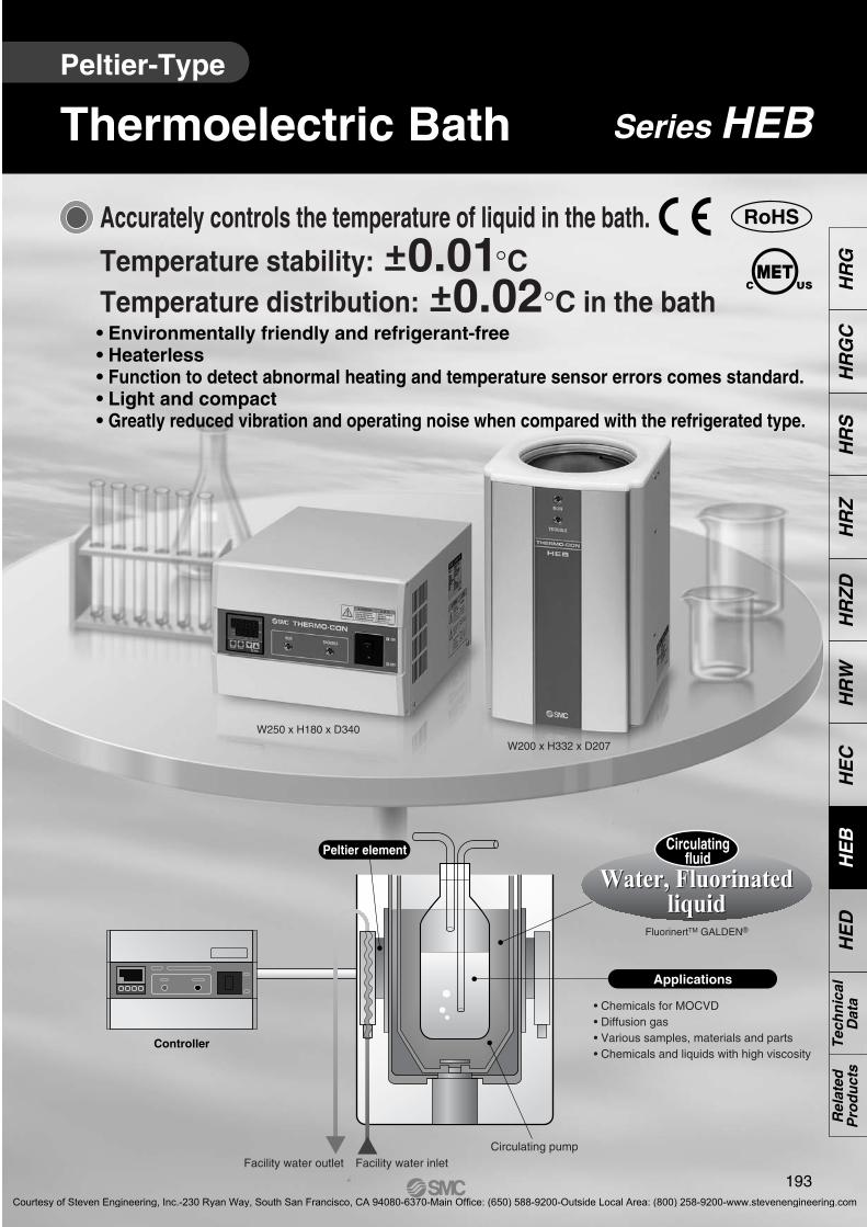
Series HEBThermoelectric BathPeltier-Type
RoHS
• Environmentally friendly and refrigerant-free• Heaterless• Function to detect abnormal heating and temperature sensor errors comes standard.• Light and compact• Greatly reduced vibration and operating noise when compared with the refrigerated type.
Accurately controls the temperature of liquid in the bath.
Temperature stability: 0.01°CTemperature distribution: 0.02°C in the bath+–
+–
W250 x H180 x D340
W200 x H332 x D207
Peltier element
Water, Fluorinatedliquid
Water, Fluorinatedliquid
Circulating pumpFacility water outlet Facility water inlet
Applications
• Chemicals for MOCVD• Diffusion gas• Various samples, materials and parts• Chemicals and liquids with high viscosity
193
HR
GH
RG
CH
RS
HR
Z
HR
ZD
H
RW
HE
CH
EB
HE
DT
ech
nic
alD
ata
Rel
ated
Pro
du
cts
Oncho-C.qxd 11.2.7 1:53 PM Page 193
Courtesy of Steven Engineering, Inc.-230 Ryan Way, South San Francisco, CA 94080-6370-Main Office: (650) 588-9200-Outside Local Area: (800) 258-9200-www.stevenengineering.com

Features
Application Examples
Principle of Peltier Device (Thermo-module, Thermoelectric device)
Various chemical processesPhysical and chemical analysisVarious testsSemiconductor
Facility water
Recirculating fluid
Current Heat suction (cooling)
Heat generation (heating)
N P
DC power supply
HeatingRecirculating fluid
Current Heat radiation (heating)
Heat suction (cooling)
N P
DC power supply
Cooling
Circulating pump
Exclusively devel-oped dual tank con-struction to provide consistent tempera-ture at any position in the bath
Peltier element
(Thermo-module,Thermoelectricdevice)
Temperature sensor
• Accurate display by measuring the circulating fluid with a temperature sensor directly
Evaporation of chemicalsfor MOCVD
Temperature control ofdiffusion gas
Thermal test with immersion Temperature control ofvarious samples,
materials and parts
Indirect temperature control ofchemicals and liquids
with high viscosity
A Peltier device (thermo-module, thermo-electric device) is a plate type element, inside which P-type semiconductors and N-type semiconductors are located alter-nately. If direct current is supplied to the Peltier device, heat is transferred inside the device, and one face generates heat and increases temperature while the other face sucked heat and decreases temperature. Therefore, changing thedirection of the current supplied to the Peltier device can achieve heating and cooling operation. This method has a fast response and can shift quickly between heating and cooling, so temperature can be controlled very precisely.
Electron flow Electron hole flow
Facility water
Electron flow Electron hole flow
194
Oncho-C.qxd 11.2.7 1:53 PM Page 194
Courtesy of Steven Engineering, Inc.-230 Ryan Way, South San Francisco, CA 94080-6370-Main Office: (650) 588-9200-Outside Local Area: (800) 258-9200-www.stevenengineering.com

How to Order
Combination (Controller + Liquid tank)
Liquid tank
Controller
AHEB C W 10002
AHEBC002 C
WHEB C H 10002
RoHSPeltier-TypeThermoelectric Bath
Series HEB
C Round
Shape of bath
002 140 W
Cooling capacity
W Water-cooled
Radiating method
AB
RS-485
RS-232C
Communication
Nil
NRc1/4
NPT1/4
Option
∗ The option should be specified when ordering.
10 ø130 x H180
Liquid tank size
ControllerLiquid tank
C Round
Shape of bath
002 140 W
Cooling capacity
Liquid tank
W Water-cooled
Radiating method
Nil
NRc1/4
NPT1/4
Option
∗ The option should be specified when ordering.
10 ø130 x H180
Liquid tank size
ControllerAB
RS-485
RS-232C
Communication
195
HR
GH
RG
CH
RS
HR
Z
HR
ZD
H
RW
HE
CH
EB
HE
DT
ech
nic
alD
ata
Rel
ated
Pro
du
cts
Oncho-C.qxd 11.2.7 1:53 PM Page 195
Courtesy of Steven Engineering, Inc.-230 Ryan Way, South San Francisco, CA 94080-6370-Main Office: (650) 588-9200-Outside Local Area: (800) 258-9200-www.stevenengineering.com

Series HEB
Specifications (For details, please consult our “Product Specifications” information.)
Cir
cula
tin
gfl
uid
sys
tem
Fac
ility
wat
ersy
stem
Ele
ctri
cal
syst
em
Note 1) GALDEN® is a trademark of Solvay Solexis and FluorinertTM is a trademark of 3M. For other fluids, please contact SMC.Note 2) Determined under the following conditions: water as the recirculating fluid, set temperature 25°C, facility water temperature 25°C, flow rate 3 L/min, ambient temperature
25°C, and sealed from outside air with a lid.Note 3) Differs depending on the operating conditions.Note 4) An appropriate range is from 3 to 5 L/min. To prevent damage to the radiating system, do not supply a flow over the maximum flow rate of 8 L/min.Note 5) When the temperature is set high, the liquid temperature inside of the liquid tank and the temperature inside of the thermostat could differ greatly depending on the heating
mode at start-up, and the thermostat could then begin operating and stop the output. Confirm that there is no problem by carrying out an operating test beforehand.
Model HEBC002-WA10 HEBC002-WB10Cooling method
Radiating method
Control method
Ambient temperature/humidity
Communications
Weight
Accessories
Safety standards
Application fluid Note 1)
Set temperature range Note 1) Note 5)
Cooling capacity Note 2)
Heating capacity Note 2)
Temperature stability Note 3)
Temperature distribution Note 3)
Tank dimensions
Temperature
Pressure range
Flow rate Note 4)
Port size
Wetted parts material
Power supply
Overcurrent protector
Current consumption
Peltier device (Thermo-module, Thermoelectric device)
Liquid tank: Water-cooled, Controller: Forcible air-cooled
Cooling/Heating automatic shift PID control
10 to 35°C, 35 to 80%RH
Clear water, Fluorinated liquid (FluorinertTM FC-3283, GALDEN® HT135, HT200)
–15.0 to 60.0°C (5 to 60°C for water)
140 W (Water)
300 W (Water)
±0.01°C±0.02°C
Internal diameter ø130 x Liquid level 188 mm
10 to 35°C (no condensation)
0.5 MPa or less
3 to 5 L/min
IN/OUT: Rc1/4
Stainless steel 303, Stainless steel 304, FEP, A6063 (anodized)
Single-phase, 100 to 240 VAC, 50/60 Hz
10 A
4 A (100 VAC) to 2 A (240 VAC)
Power cable (2 m), DC cable, Signal cable (3 m each)
CE marking, UL (NRTL) standard
RS-485 RS-232C
1) Overheating of liquid tank (which activates the thermostat)2) Controller output voltage reduction3) Controller fan rotation stopped
Liquid tank: Approx. 8.5 kgController: Approx. 6.5 kg
Alarm(With alarm output connector)
196
Oncho-C.qxd 11.2.7 1:53 PM Page 196
Courtesy of Steven Engineering, Inc.-230 Ryan Way, South San Francisco, CA 94080-6370-Main Office: (650) 588-9200-Outside Local Area: (800) 258-9200-www.stevenengineering.com

Cooling Capacity Heating Capacity
Pressure Loss in Facility Water Circuit
Parts Description
Flow rate (L/min)
Pre
ssur
e lo
ss (
kPa)
0
10
20
30
40
50
60
70
80
0 1 2 3 4 5 6 7 8
Time (minute)
Circ
ulat
ing
fluid
tem
pera
ture
(°C
)
–20
–15
–10
–5
0
5
10
15
20
25
30
0 20 40 60 80 100 120 140 160 180
GALDEN® HT200
Fluorinert™ FC-3283
Circ
ulat
ing
fluid
tem
pera
ture
(°C
)
20
25
30
35
40
45
50
55
60
65
Time (minute)
0 10 20 30 40 50 60 70 80
GALDEN® HT200
Fluorinert™ FC-3283
RUN LED
TROUBLE LED
RUN LED TROUBLE LED
Water
Ambient temperature: 25°CLiquid level: 180 mm (Liquid temperature: 25°C)Facility water temperature: 25°CFacility water flow rate: 3 L/minShut out from outside with a lid (polystyrene foam)
Water
Ambient temperature: 25°CLiquid level: 180 mm (Liquid temperature: 25°C)Facility water temperature: 25°CFacility water flow rate: 3 L/minShut out from outside with a lid (polystyrene foam)
The values shown on the performance chart are not guaranteed, buttypical. Allow margins for safety when selecting the model.
Signal connector
Tank
Facility water inlet
Facility water outlet
DC connector
Fan
Signal connector
Alarm output connector
DC output connector
Power connector
Communication connector
Display/Operation panel
Power switch
197
Peltier-Type/Thermoelectric Bath Series HEB
HR
GH
RG
CH
RS
HR
Z
HR
ZD
H
RW
HE
CH
EB
HE
DT
ech
nic
alD
ata
Rel
ated
Pro
du
cts
Oncho-C.qxd 11.2.7 1:53 PM Page 197
Courtesy of Steven Engineering, Inc.-230 Ryan Way, South San Francisco, CA 94080-6370-Main Office: (650) 588-9200-Outside Local Area: (800) 258-9200-www.stevenengineering.com

Dimensions
Liquid tank
Internal dimensions of liquid tank
Controller
LOW
198
(35)
ø35
9
10
ø147
I.D.130
30
332
200
138
198
(9)
THERMO-CON
30
207
138
(204) 15
INDC
SIGNAL
OUT
WARNING
WARNING
25
83
49
148
4141
WARNING
THERMO-CON
340 (75)
60
37
230
68
116
20
COMMUNICATION
SIGNAL
ALARM
DCOUTPUT
AC
8622
19.596
19030
138 99
62
36
SV
PV
DIRDYCOMAL2
OUT1
OUT2
AL1
FUNCMODE
WARNING
53102
95
180
250
170
Model no. label
Signal cable
DC cable
Signal connector
Warning label
Facility water inletRc1/4
For -N spec.NPT1/4
DC connectorFacility water outletRc1/4
For -N spec.NPT1/4
Temperature sensor
Rubber foot Circulating pump
RUN LED (Green)
TROUBLE LED (Red)
Min
. liq
uid
leve
l 76
Max
. liq
uid
leve
l 18
8
TROUBLE LED (Red)
RUN LED (Green)
Display/Operation panel
AirIN
Power switch
AirIN
Ventilation hole (Air IN)The opposite face has the same shape.
Model no. label
FanDC cable
Signal cable
Air OUT
Warning label
Power cable
Fan (Air OUT)
Alarm output connector
Signal connector
Communication connector
Power connector
DC output connector
(ø79)
198
Series HEB
Oncho-C.qxd 11.2.7 1:53 PM Page 198
Courtesy of Steven Engineering, Inc.-230 Ryan Way, South San Francisco, CA 94080-6370-Main Office: (650) 588-9200-Outside Local Area: (800) 258-9200-www.stevenengineering.com

9 87
6
54
3
21
6 7 8 9
12 3 4
5
Connectors
Pin No.Signal contents
12345
6-9
HEBC002-WA10RS-485 T/R (A)RS-485 T/R (B)
UnusedUnusedUnusedUnused
HEBC002-WB10Unused
RS-232C RXRS-232C TX
UnusedRS-232C SG
Unused
Water Bath and Controller Connection
� Connector for water baths
Nanaboshi Electric Mfg. Co., Ltd.: NJC-245-RM UL CSA
Hirose Electric Co., Ltd.: CDA-15PHolding screw M2.6
Connection
Power Cable Connection Connector for External Equipment
� Alarm output connectorHirose Electric Co., Ltd.: CDE-9PHolding screw M2.6Fitting connector: CDE-9S or equivalent
� Communication connectorHirose Electric Co., Ltd.: CDE-9SHolding screw M2.6Fitting connector: CDE-9P or equivalent
DC connector (male connector) Signal connector (male connector)
� Connector for controllers
Nanaboshi Electric Mfg. Co., Ltd.: NJC-245-RF UL CSA
Hirose Electric Co., Ltd.: CDA-15SHolding screw M2.6
DC connector (female connector) Signal connector (female connector)
Connection Connection
� Connection cable
Nanaboshi Electric Mfg. Co., Ltd.: NJC-245-PF UL CSA
Female connector
Hirose Electric Co., Ltd.: CDA-15SHolding screw M2.6
Female connector
Nanaboshi Electric Mfg. Co., Ltd. NJC-245-PM UL CSA
Male connector Hirose Electric Co., Ltd.: CDA-15PHolding screw M2.6
Male connector
Connection
DC cable Signal cable
Connection
Pin No. Signal contents12
3-456
7-9
Contact for upper/lower temperature limit deviation alarm (open when alarm occurs)
Upper/lower temperature limit deviation alarm common
UnusedContact for output cut-off alarm (open when alarm occurs)
Common for output cut-off alarmUnused
Black 1Black 2
Green/Yellow
AWG14
� Connector for controllers
IEC60320 C-14 or equivalent
Male connector
Power connector
� Power cable
Connector sideIEC60320 C-13 or equivalent
Female connector
Signal contents100 to 240 VAC (L)100 to 240 VAC (N)
PE
Alarm output connectorD-sub 9 pin (male type)
Communication connectorD-sub 9 pin (female type)
Connectors that fit with a communication connector and an alarm output connector should be prepared by customer.
MaintenanceMaintenance of this unit is performed only in the form of return to and repair at SMC’s site. As a rule, SMC will not conduct on-site maintenance. Separately, the following parts have a limited life and need to be replaced before the life ends.
Description
Circulating pump
Fan
DC power supply
The circulating fluid cannot be fed due to worn bearing and/or insufficient capacity of electrolytic capacitor, which results in temperature controlling failure.
The capacity of the fan lowers due to the end of lubricating performance of the bearing, which results in increase of internal temperature of the Controller. The overheat protective function at the inside of the power supply starts, the output stops and the display goes off.
Abnormal voltage is generated and the display goes off due to insufficient capacity of electrolytic capacitor.
3 to 5 years
5 to 10 years
5 to 10 years
Expected life Possible failure
Parts Life Expectation
199
Peltier-Type/Thermoelectric Bath Series HEB
HR
GH
RG
CH
RS
HR
Z
HR
ZD
H
RW
HE
CH
EB
HE
DT
ech
nic
alD
ata
Rel
ated
Pro
du
cts
Oncho-C.qxd 11.2.7 1:53 PM Page 199
Courtesy of Steven Engineering, Inc.-230 Ryan Way, South San Francisco, CA 94080-6370-Main Office: (650) 588-9200-Outside Local Area: (800) 258-9200-www.stevenengineering.com
Series HEBSpecific Product Precautions 1Be sure to read this before handling. Refer to back page 1 for Safety Instructions andback pages 2 to 5 for Temperature Control Equipment Precautions.
1. The catalog shows the specifications of the Thermoelectric Bath.1. Check detailed specifications in the separate “Product Speci-
fications”, and evaluate the compatibility of the Thermoelec-tric Bath with customer’s system.
2. The Thermoelectric Bath is equipped with a protective circuit independently, but the whole system should be designed by the customer to ensure safety.
System Design
Warning1. Do not use fluids other than those described
in the specification.Otherwise, the pump will be overloaded and may break. If such a fluid is used, please contact SMC beforehand.
2. The Thermoelectric Bath must not be ope-rated without circulating fluid. The pump breaks by empty driving.
3. The circulating fluid may evaporate, low-ering the level in the tank.Significant reduction of the fluid level can break the circulating pump as well as causing the performance to deteriorate. Use with appropriate liquid level at all times.
4. The pump can be broken by foreign objects entering the circulating pump.Control to prevent any foreign object from entering the fluid. If the fluid is fluorinated liquid and it is set to a temperature below freezing point, steam from the atmosphere will form ice (frost) when entering the fluid. Be sure to remove this ice (frost) regu-larly.
5. If water is used for the circulating fluid, set its temperature to over or more 5°C to prevent it from being frozen.
Circulating Fluid
Caution
1. The maximum operating pressure of facility water is 0.5 MPa.If this value is exceeded, the internal piping of the tank can break, causing leakage of facility water.
2. Do not supply a flow rate of 8 L/min or more which can break the facility water piping.
3. Appropriate range of the flow rate of the fa-cility water is 3 to 5 L/min.Flow rate higher than this range will not slightly affect the cool-ing and heating capacity. However, a flow rate below 3 L/min will reduce the cooling and heating capacity significantly.
Facility Water
Caution
1. The set value can be written to EEPROM, but only up to approx. 100,000 times. In particular, pay attention to how many of times the writing is performed using the communication function.
Communication
Caution
1. Avoid using the Thermoelectric Bath in an environment where it could be splashed by fluids (including mist) such as water, salt wa-ter, oil, chemicals, or solvents.
2. The Thermoelectric Bath is not designed for clean room usage.It generates dust from the pump inside the tank and the cooling fan in the controller.
3. Low molecular siloxane can damage the con-tact of the relay.Use the Thermoelectric Bath in a place free from low molecular siloxane.
4. Reserve a space of 50 mm or more at the ven-tilation hole of the controller.
Operating Environment/Storage Environment
Warning
1. The ventilation hole for radiation air must not be exposed to particles and dust as far as possible.
2. Do not let the inlet and outlet for radiation air get closed.If radiation is prevented, the internal power supply will overheat, causing the protective circuit to be activated and stopping the Thermoelectric Bath.
3. If more than one Thermoelectric Bath is used, consider their arrangement so that the down-stream sides of the Thermoelectric Bath suck radiation air from the upstream sides.
Radiation Air
Caution
Handling
Warning1. Thoroughly read the Operation Manual.
Read the Operation Manual completely before operation, and keep this manual available whenever necessary.
200
Oncho-C.qxd 11.2.7 1:53 PM Page 200
Courtesy of Steven Engineering, Inc.-230 Ryan Way, South San Francisco, CA 94080-6370-Main Office: (650) 588-9200-Outside Local Area: (800) 258-9200-www.stevenengineering.com

Series HEBSpecific Product Precautions 2Be sure to read this before handling. Refer to back page 1 for Safety Instructions andback pages 2 to 5 for Temperature Control Equipment Precautions.
1. Prevention of electric shock and fireDo not operate the switch with wet hands. Also, do not operate the Thermoelectric Bath with water or fluid left on it.
2. Action in the case of errorIf any error such as abnormal sounds, smoke, or bad smell occurs, cut off the power at once, and stop supplying facility water. Please contact SMC or a sales distributor to repair the Thermoelectric Bath.
3. Regular inspectionCheck the following items at least once a month. The inspec-tion must be done by an operator who has sufficient knowledge and experience.a) Check of displayed contents.b) Check of temperature, vibration and abnormal sounds in the
body of the Thermoelectric Bath.c) Check of the voltage and current of the power supply system.d) Check for leakage and contamination of the recirculating fluid
and intrusion of foreign objects to it.e) Check radiation air flow condition and temperature.f) Check for leakage, quality change, flow rate and temperature
of facility water.
Maintenance
Warning
201
HR
GH
RG
CH
RS
HR
Z
HR
ZD
H
RW
HE
CH
EB
HE
DT
ech
nic
alD
ata
Rel
ated
Pro
du
cts
Oncho-C.qxd 11.2.7 1:53 PM Page 201
Courtesy of Steven Engineering, Inc.-230 Ryan Way, South San Francisco, CA 94080-6370-Main Office: (650) 588-9200-Outside Local Area: (800) 258-9200-www.stevenengineering.com

202
Oncho-C.qxd 11.2.7 1:53 PM Page 202
Courtesy of Steven Engineering, Inc.-230 Ryan Way, South San Francisco, CA 94080-6370-Main Office: (650) 588-9200-Outside Local Area: (800) 258-9200-www.stevenengineering.com