thermoelastic vibration analysis of disc brake based on
TRANSCRIPT

ISSN PRINT 1392-8716, ISSN ONLINE 2538-8460, KAUNAS, LITHUANIA 1
Thermoelastic vibration analysis of disc brake based on multi-physical field coupling method
Sen Zhang1, Jian Zhang2 Binzhou University, Binzhou, China 1Corresponding author E-mail: [email protected], [email protected] Received 6 January 2019; received in revised form 17 June 2019; accepted 2 July 2019 DOI https://doi.org/10.21595/jve.2019.20505
Copyright © 2020 Sen Zhang, et al. This is an open access article distributed under the Creative Commons Attribution License, which permits unrestricted use, distribution, and reproduction in any medium, provided the original work is properly cited.
Abstract. Thermoelastic vibration is the main cause of brake jitter and noise, including significant fluctuations in temperature, thermal stress, structure size and braking moment. In order to improve the reliability of thermoelastic vibration results, a multi-physical field coupling modeling method is proposed in this paper, which can realize the simultaneous calculation of temperature field, stress field and air flow field. Firstly, the theoretical analysis of the whole braking coupling process and feasibility analysis is carried out. Secondly, ABAQUS solid model and FLUENT fluid model are established respectively, and MPCCI is used to share the parameters of the two models, including temperature, node displacement and heat transfer coefficient. Finally, different paths are constructed to study the fluctuation of thermoelastic parameters in different directions. The research conclusion of thermoelastic vibration can provide important basis for optimization of brake NVH (Noise Vibration and Harshness). Keywords: thermoelastic vibration, multi-physical field coupling, disc brake, modeling, NVH.
1. Introduction
When disc brake is working, a large amount of heat generated by friction between brake disc and brake pad is transmitted to the friction pair through the thermal diffusion process of different materials [1]. This thermal instability will generate a tropical zone on the surface of the brake disc, which will lead to significant fluctuations in thermoelastic vibration, including temperature, thermal stress, deformation and brake moment. In general, the thermoelastic vibration generated during braking not only affects the comfort and safety of automobiles, but also accelerates the aging and fatigue damage [2] of the relevant components of the braking system, affects the safety and reliability of automobiles, and increases the cost of quality assurance and maintenance of the braking system.
Essentially, the whole friction braking is a complex coupling process of temperature field, stress field and air flow field. At present, coupled calculation of three physical fields has been applied in some fields, but rarely in the field of braking. Basically, all the research on braking is simplified and limited to only two physical fields coupling because of the complexity of computation, including thermo-mechanical coupling [3-7] and fluid-structure coupling [8, 9]. The coupled calculation of temperature field and stress field can be realized precisely by thermo-mechanical coupling, but the dynamic change of heat transfer coefficient in time and space that caused by air flow cannot be considered by this method, which will occur errors in temperature field results inevitably. The heat transfer calculation between air and brake disc surface can be realized by fluid- structure coupling, but it cannot realize the calculation of stress field, and the error of heat source equation is quite obvious.
In order to solve the current research deficiencies, the fluid-solid-thermal coupling method is presented and proved to complete the frictional thermodynamic analysis of the brake in the paper for the first time, including the designed numerical simulation scheme and NVH bench test. In addition, considering the computational efficiency and accuracy, the coupling calculation of temperature field, stress field and air flow field would be realized by both tight coupling (realized

THERMOELASTIC VIBRATION ANALYSIS OF DISC BRAKE BASED ON MULTI-PHYSICAL FIELD COUPLING METHOD. SEN ZHANG, JIAN ZHANG
2 JOURNAL OF VIBROENGINEERING. FEBRUARY 2020, VOLUME 22, ISSUE 1
by coupled equations) and loose coupling (realized by iterative calculation of shared parameters), which is quite different from other experts’ existing research. The scheme can accurately calculate the temperature field, stress field, size fluctuation and braking moment fluctuation of the brake disc.
2. Construction and setting of coupling model
2.1. Theoretical analysis of coupling process
The thermodynamics characteristic of brake disc caused by friction is one kind of non-equilibrium problem [10]. The phenomenological equation can be expressed in space 𝑉 as follows: ∂𝑍∂𝜏 = ∂(𝜌𝑧)∂𝜏 𝑑𝑉 = (−∇ ⋅ 𝐽 + 𝜎 )𝑑𝑉, (1)
where 𝜌𝑧 is density of extensive quantity 𝑍, 𝐽 is density of for extended flow, 𝜎 is generation rate of extensive quantity, 𝜏 is time. Assume that there are 𝑖 kinds of forces in the friction system. According to Newton’s second law and the symmetry of the stress tensor, the momentum equation of the brake disc can be deduced as follows:
𝜌 𝑑𝑈𝑑𝜏 = −∇ ⋅ 𝑃 + 𝜌 𝐹 , (2)
where 𝑈 is the velocity vector of center of mass of brake disc, 𝜌 is density of the disc, 𝑃 is stress tensor, 𝐹 is the volume force of each function component.
Ignoring chemical reaction factor between the brake disc and brake pad, the entropy balance equation of brake disc can be deduced by the momentum equation, mass and energy conservation laws as followed: 𝑑𝑠𝑑𝜏 = −∇ ⋅ 𝑠𝑈 + 𝐽𝑇 − 𝜇𝑇 𝐽 + 𝐽 ⋅ ∇ 1𝑇 + 𝐽 ⋅ −∇ 𝜇𝑇 + 𝑀∑ 𝐹𝑇 − 1𝑇Ⅱ:∇𝑈, (3)
where 𝑠 is the entropy density, 𝐽 is density of heat flow rate, 𝐽 and 𝜇 are respectively diffusion flow and chemical potential of the material, 𝑇 is temperature, 𝑀 is the molar mass, II is interfacial stress tensor. The entropy balance equation can fully express the fluid-thermal-structural coupling state of the brake disc.
According to the energy conservation equation, the three-dimensional transient heat transfer control equation of the brake disc can be obtained as follows: ∂𝑇∂𝑡 = 𝑎 ∂ 𝑇∂𝑥 + ∂ 𝑇∂𝑦 + ∂ 𝑇∂𝑧 + Φ𝜌 𝑐 , (4)
where 𝑎 is the thermal diffusivity of brake disc, which is related to material quality, unit of m2/s. 𝑇 is temperature, unit of K. Φ is internal heat source, unit of J/m3. Convective heat transfer is a ubiquitous physical phenomenon in nature, which is more
complicated than pure heat conduction. Therefore, the static convective heat transfer coefficient is generally calculated in engineering, but the accuracy is limited. In order to obtained more accurate results, the dynamic change of convection heat transfer coefficient in space is considered in the paper.
The contact surface between the brake pad and brake disc is discrete. Therefore, the actual

THERMOELASTIC VIBRATION ANALYSIS OF DISC BRAKE BASED ON MULTI-PHYSICAL FIELD COUPLING METHOD. SEN ZHANG, JIAN ZHANG
ISSN PRINT 1392-8716, ISSN ONLINE 2538-8460, KAUNAS, LITHUANIA 3
contact area consists of all the contact points and determines the size of the friction heat source. According to Uppal and Probert’s research, it can be known that the contact points will remain or even decrease along with the increase of the actual contact area if the brake pressure increases to the critical load. Thus, it can be seen that the braking torque will not always increase when the brake pressure is increasing.
In the braking process, the contact of friction pair has three statuses, including elastic, plastic and middle (elastic-plastic) forms, and the increase rate of the actual contact area in the elastic state is smaller than that of the plastic state [11]. According to the contact point of the spherical micro convex body theory, when 𝑃 = 2.76𝜏 (where 𝑃 is actual contact area center pressure, 𝜏 is ultimate tangential stress), plastic deformation will occur at the contact surface. The condition of the elastic-plastic deformation on the surface of the brake disc can be expressed by Tabor’s depth of press calculation method as follows: 𝑎𝑟 = 𝑘 𝜎 (1 − 𝜇 )𝐸 , (5)
where 𝑎 is the contact spot radius, 𝑟 is spherical micro convex body radius, 𝜎 denotes the average shear stress, 𝑘 is a scaling factor (determined by ratio of the average shear stress and the effective yield stress).
The influence of surface profile on the elastic-plastic state can be expressed by Williamson and Greenwood index method as shown in Eq. (6):
𝜙 = E′𝐻 𝜎𝑟 . = 1𝐻 1 − 𝜇E + 1 − 𝜇E 𝜎𝑟 . , (6)
where 𝜎 is the standard deviation of the profile, 𝐸′ is the average elastic modulus of brake pad and brake disc, 𝐻 is hardness of the brake disc, 𝜇 and 𝐸 , 𝜇 and 𝐸 are respectively Poisson’s ratio and elastic modulus of brake disc and brake pad. In unit load, when 𝜙 < 0.6, elastic state will remain, and when 𝜙 > 1, the plastic state will occur.
In the frictional thermal analysis of disc brake, many scholars assume that the heat flux on the two contact surfaces is equally distributed, which is unreasonable in practice. The frictional heat flux on the interface caused by sliding is related to the thermal resistance of the two friction surfaces. At present, it is still quite difficult to quantitatively determine the thermal resistance between friction interfaces. According to the calculation principle of friction and wear, the reasonable thermal conduction boundary conditions between the friction pairs can be approximated as follows. In the real contact area, the temperature of each contact point pair composed of the contact point of the brake pad and the brake pad must be equal, but outside the real contact area, the surface temperature is not necessarily equal, that is, the temperature of the contact point pair is not necessarily equal: 𝑇 = 𝑇 , 𝑞 + 𝑞 = 𝑞, (7)
where 𝑇 and 𝑇 is the characteristic temperature of contact point between the brake pad and brake disc, unit of K. 𝑞 and 𝑞 is heat flux density of contact surfaces between brake disc and brake disc , unit of J/(m2·s). 𝑞 is the total heat flux, unit of J/(m2·s).
The heat flux distribution coefficient of brake pad is:
𝜉 = 𝜆 𝑐 𝜌𝜆 𝑐 𝜌 , (8)
where 𝜆 and 𝜆 are the thermal conductivity of the brake pad and the brake disc, unit of W/(m·K).

THERMOELASTIC VIBRATION ANALYSIS OF DISC BRAKE BASED ON MULTI-PHYSICAL FIELD COUPLING METHOD. SEN ZHANG, JIAN ZHANG
4 JOURNAL OF VIBROENGINEERING. FEBRUARY 2020, VOLUME 22, ISSUE 1
𝑐 and 𝑐 are the specific heat of the brake pad and the brake disc, unit of J/(kg·K). 𝜌 and 𝜌 are the density of the brake pad and the brake disc, unit of kg/m3.
According to Eq. (8), the brake pads of different materials have important influence on heat flow distribution. For example, the heat flow distribution coefficient of semi-metallic materials is 9.8, and the heat flow accounts for only 9.3 %.
According to Hooke’s law, the total strain component of the thermoelastic element in Cartesian coordinate system 𝑂𝑥𝑦𝑧 can be obtained as follows:
⎩⎪⎨⎪⎧𝜀 = 1𝐸 𝜎 − 𝜇 𝜎 + 𝜎 + 𝛼𝑇,𝜀 = 1𝐸 𝜎 − 𝜇(𝜎 + 𝜎 ) + 𝛼𝑇,𝜀 = 1𝐸 𝜎 − 𝜇 𝜎 + 𝜎 + 𝛼𝑇, (9)
⎩⎪⎨⎪⎧𝛾 = 2(1 + 𝜇)𝐸 𝜏 ,𝛾 = 2(1 + 𝜇)𝐸 𝜏 ,𝛾 = 2(1 + 𝜇)𝐸 𝜏 , (10)
where 𝛼 is the thermal expansion coefficient of brake disc, 𝜀 , 𝜀 , 𝜀 is positive strain in different direction, 𝛾 , 𝛾 , 𝛾 is shear strain, 𝜎 , 𝜎 , 𝜎 is positive stress, 𝜏 , 𝜏 , 𝜏 is shear stress, 𝜇 is Poisson ratio; 𝐸 is modulus of elasticity.
It can be obtained in two-dimensional 𝑂𝑥𝑦 plane as followed:
⎩⎪⎨⎪⎧𝜀 = 1𝐸 𝜎 − 𝜇𝜎 + 𝛼𝑇,𝜀 = 1𝐸 𝜎 − 𝜇𝜎 + 𝛼𝑇,𝛾 = 2(1 + 𝜇)𝐸 𝜏 . (11)
The geometric equation of strain components can be expressed as:
⎩⎪⎪⎨⎪⎪⎧𝜀 = ∂𝑢∂𝑥 ,𝜀 = ∂𝑣∂𝑦 ,𝛾 = ∂𝑣∂𝑥 + ∂𝑢∂𝑦 . (12)
The two-dimensional temperature-displacement coupling differential equation (expression of tight coupling) of brake disc can be derived as followed:
⎩⎪⎨⎪⎧∂ 𝑢∂𝑥 + 1 − 𝜇2 ∂ 𝑢∂𝑦 + 1 + 𝜇2 ∂ 𝑣∂𝑥 ∂𝑦 − (1 + 𝜇)𝛼 ∂𝑇∂𝑥 = 0,∂ 𝑣∂𝑦 + 1 − 𝜇2 ∂ 𝑣∂𝑥 + 1 + 𝜇2 ∂ 𝑢∂𝑥 ∂𝑦 − (1 + 𝜇)𝛼 ∂𝑇∂𝑦 = 0. (13)
THERMOELASTIC VIBRATION ANALYSIS OF DISC BRAKE BASED ON MULTI-PHYSICAL FIELD COUPLING METHOD. SEN ZHANG, JIAN ZHANG
ISSN PRINT 1392-8716, ISSN ONLINE 2538-8460, KAUNAS, LITHUANIA 5
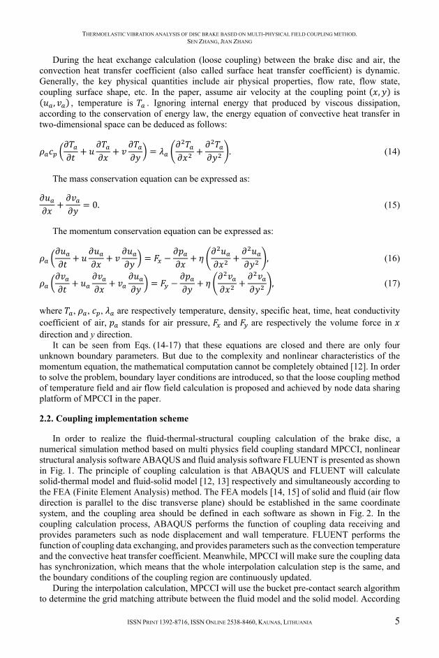
During the heat exchange calculation (loose coupling) between the brake disc and air, the convection heat transfer coefficient (also called surface heat transfer coefficient) is dynamic. Generally, the key physical quantities include air physical properties, flow rate, flow state, coupling surface shape, etc. In the paper, assume air velocity at the coupling point (𝑥,𝑦) is (𝑢 ,𝑣 ) , temperature is 𝑇 . Ignoring internal energy that produced by viscous dissipation, according to the conservation of energy law, the energy equation of convective heat transfer in two-dimensional space can be deduced as follows:
𝜌 𝑐 𝜕𝑇𝜕𝑡 + 𝑢 𝜕𝑇𝜕𝑥 + 𝑣 𝜕𝑇𝜕𝑦 = 𝜆 𝜕 𝑇𝜕𝑥 + 𝜕 𝑇𝜕𝑦 . (14)
The mass conservation equation can be expressed as: 𝜕𝑢𝜕𝑥 + 𝜕𝑣𝜕𝑦 = 0. (15)
The momentum conservation equation can be expressed as:
𝜌 𝜕𝑢𝜕𝑡 + 𝑢 𝜕𝑢𝜕𝑥 + 𝑣 𝜕𝑢𝜕𝑦 = 𝐹 − 𝜕𝑝𝜕𝑥 + 𝜂 𝜕 𝑢𝜕𝑥 + 𝜕 𝑢𝜕𝑦 , (16)𝜌 𝜕𝑣𝜕𝑡 + 𝑢 𝜕𝑣𝜕𝑥 + 𝑣 𝜕𝑢𝜕𝑦 = 𝐹 − 𝜕𝑝𝜕𝑦 + 𝜂 𝜕 𝑣𝜕𝑥 + 𝜕 𝑣𝜕𝑦 , (17)
where 𝑇 , 𝜌 , 𝑐 , 𝜆 are respectively temperature, density, specific heat, time, heat conductivity coefficient of air, 𝑝 stands for air pressure, 𝐹 and 𝐹 are respectively the volume force in 𝑥 direction and y direction.
It can be seen from Eqs. (14-17) that these equations are closed and there are only four unknown boundary parameters. But due to the complexity and nonlinear characteristics of the momentum equation, the mathematical computation cannot be completely obtained [12]. In order to solve the problem, boundary layer conditions are introduced, so that the loose coupling method of temperature field and air flow field calculation is proposed and achieved by node data sharing platform of MPCCI in the paper.
2.2. Coupling implementation scheme
In order to realize the fluid-thermal-structural coupling calculation of the brake disc, a numerical simulation method based on multi physics field coupling standard MPCCI, nonlinear structural analysis software ABAQUS and fluid analysis software FLUENT is presented as shown in Fig. 1. The principle of coupling calculation is that ABAQUS and FLUENT will calculate solid-thermal model and fluid-solid model [12, 13] respectively and simultaneously according to the FEA (Finite Element Analysis) method. The FEA models [14, 15] of solid and fluid (air flow direction is parallel to the disc transverse plane) should be established in the same coordinate system, and the coupling area should be defined in each software as shown in Fig. 2. In the coupling calculation process, ABAQUS performs the function of coupling data receiving and provides parameters such as node displacement and wall temperature. FLUENT performs the function of coupling data exchanging, and provides parameters such as the convection temperature and the convective heat transfer coefficient. Meanwhile, MPCCI will make sure the coupling data has synchronization, which means that the whole interpolation calculation step is the same, and the boundary conditions of the coupling region are continuously updated.
During the interpolation calculation, MPCCI will use the bucket pre-contact search algorithm to determine the grid matching attribute between the fluid model and the solid model. According

THERMOELASTIC VIBRATION ANALYSIS OF DISC BRAKE BASED ON MULTI-PHYSICAL FIELD COUPLING METHOD. SEN ZHANG, JIAN ZHANG
6 JOURNAL OF VIBROENGINEERING. FEBRUARY 2020, VOLUME 22, ISSUE 1
to the physical quantity, the coupling data can be divided into non-conservation data (such as displacement, velocity, temperature, etc.) and conservation data (such as quality, flow, etc.). In the pre-processing of MPCCI, the coupling area and calculation time step will be defined. In order to ensure the data is shared properly, the fluid model is set as “data exchange”, and the solid model is set as “data receiving”.
ABAQUSmodel
FLUETTmodelmodel pre-processing
definition of coupling areaand code
scaninginp file
scaningcae file
read
exchange
ABAQUSsolver
MPCCIsolver
filmtemperature FLUENT
solver
walltemperature
convective heattransfer coefficient
temperaturefield
couplingparameters
airfieldpost-processing
iterative operation
read
MPCCIGUI
exchange
stressfield
Fig. 1. Principle of coupling calculation
Fig. 2. The FEA model of coupling calculation
2.3. Model pretreatment and analysis of ABAQUS
In order to ensure the computational efficiency and convergence, the element partition and local optimization method are used in hexahedral mesh division of both model as shown in Fig. 2. The mesh type of C3D8HT in ABAQUS model is chosen, of which cells number is 17370 and nodes number is 25821. Temperature effects are considered during the material properties setting, so that the results can be more accurate.
Table 1. Material properties of friction pairs in different temperature Friction pairs 𝑇 / °C 𝜆 / (W·m-1·K-1) 𝑐 / (J·kg-1·K-1) 𝛼 / (10-6 ·K-1) 𝐸 / GPa
Disc brake
20 42.38 503 4.39 105 100 43.06 530 11.65 95 200 44.23 563 12.84 90 300 45.55 611 13.58 90
Disc pad
20 0.9 1200 10 2.2 100 1.1 1250 18 1.3 200 1.2 1295 30 0.53 300 1.15 1320 32 0.32
In the preprocessing of the model, the main parameters and boundary conditions are set as follows.
(1) The analysis step is established by means of temperature-displacement coupling. Considering the convergence and calculation efficiency, the time step is 0.001 s and the load step is 10000. The surface coupling reference point method is applied to the degree of freedom constraint of brake disc and brake pad. The radiant emissivity is defined as 0.28, the heat flux distribution coefficient is calculated by Eq. (8), and the interface thermal conductivity is defined as followed:
ℎ = 1.13𝑘tan𝜃𝜎 𝑃𝐻 . , (18)
where ℎ is interface thermal conductivity between brake disc and brake pad, unit of K/W. 𝑘 is the minimum value of thermal conductivity of friction pairs, W/(m·K). tan𝜃 is mean value of

THERMOELASTIC VIBRATION ANALYSIS OF DISC BRAKE BASED ON MULTI-PHYSICAL FIELD COUPLING METHOD. SEN ZHANG, JIAN ZHANG
ISSN PRINT 1392-8716, ISSN ONLINE 2538-8460, KAUNAS, LITHUANIA 7
absolute slope of contour. 𝑃 is brake pressure, unit of Pa. 𝐻 is microhardness, kg/m2. 𝜎 is contact stress, unit of Pa.
(2) The brake pressure amplitude is set as 3 MPa, the brake force acting time is set as 1 s, and the brake disc speed amplitude is set as 46.4 rad/s. In order to match the test conditions, the initial temperature of the brake disc brake is defined as 100 °C, and set the surface of the brake disc as coupling surface.
2.4. Model pretreatment analysis of FLUENT
The fluid model includes the moving region and the static zone. The moving region is mainly used to simulate the rotation of the brake disk and calculate the flow field around the coupling surface. The static region is mainly used to provide the inlet and outlet of air flow. Considering the working load and calculation efficiency of the fluid model, the sliding grid method [16, 17] is used to realize the wall movement in the paper. In each time step, the flow variables on the interface nodes need to be transferred to realize the coupling solution of the two regions. This method can save a lot of calculation costs compared with the grid reconstruction method, and is conducive to improving the calculation efficiency of multi-physical field coupling.
As a typical near-wall mesh, boundary layer meshes have different grid requirements for different near-wall treatments [18]. In order to guarantee the quality of the boundary layer mesh, the dimensionless sublayer velocity 𝑢 and the distance to the wall 𝑦 should be defined:
𝑦 = 𝑦 ⋅ 𝜏 𝜌𝜂 , 𝑢 = 𝑢𝜏 𝜌⁄ , (19)
where 𝑢 is air velocity, unit of m/s. 𝜏 is wall shear stress, Pa. 𝑦 is normal distance along the wall, unit of m.
According to Plante’s theory, the relationship between dimensionless parameters 𝑢 and 𝑦 can be obtained by different test method as shown in Fig. 3. It can be seen that there are mainly three different boundary layer structures as follows.
Laminar sublayer: 0 < 𝑦 < 5, 𝑢 = 𝑦 . Buffer layer: 5 ≤ 𝑦 ≤ 30, 𝑢 = 5ln𝑦 − 3.25. Turbulent core layer: 𝑦 > 30, 𝑢 = 2.5ln𝑦 + 5.5. According to the Reynolds number formula, it can be known that the braking process is a
typical high turbulence model. Under the condition of multi-physical field coupling analysis, the wall function method is more reasonable. The initial conditions of the fluid model and the settings of the solver are shown in Table 2, and the high turbulence RNG 𝑘-𝜀 model [19] is used.
Table 2. Initial conditions and solver settings Parameter Value setting Air inlet 𝑈 = 20 m/s, 𝑡 = 26.8 °C Air outlet 𝑃 = 101325 Pa, 𝑡 = 26.8 °C
Coupling wall Stationary wall, 𝑡 = 𝑡
Interface Angular velocity in moving zone, 𝜔 = 𝜔 Flux algorithm Second order upwind
Solution strategy Simple Turbulence model Rng 𝑘-𝜀 model, unbalanced wall function
The non-equilibrium wall function is used to calculate the turbulent flow energy of the near wall controlled body. Sublayer structures under the wall rule can be divided into laminar boundary layer (also known as linear or viscous sublayer) and turbulent boundary layer (turbulent core layer) as shown in Fig. 4. According to the average velocity wall method defined by FLUENT wall function, the expressions of dimensionless sublayer velocity 𝑈∗ and height 𝑦∗ in the first layer

THERMOELASTIC VIBRATION ANALYSIS OF DISC BRAKE BASED ON MULTI-PHYSICAL FIELD COUPLING METHOD. SEN ZHANG, JIAN ZHANG
8 JOURNAL OF VIBROENGINEERING. FEBRUARY 2020, VOLUME 22, ISSUE 1
grid of node p are given as follows:
𝑈∗ ≡ 𝑈 𝐶 ⁄ 𝑘 ⁄𝜏 𝜌⁄ , 𝑦∗ ≡ 𝜌𝐶 ⁄ 𝑘 ⁄ 𝑦𝜇 , (20)
where 𝑦 is the distance from point 𝑝 to the coupling wall, 𝑈 is the average velocity of air at point, 𝜇 is dynamic viscosity coefficient of air, 𝑘 is turbulent kinetic energy at point 𝑝, 𝐶 is the coefficient of RNG turbulence model, value of 0.0845.
In the non-equilibrium wall function, the temperature wall rule is still consistent with the standard wall function, but the average velocity of turbulent core layer is more sensitive to the pressure gradient.
Fig. 3. The distribution of the boundary layer
Fig. 4. Sublayer structure under wall function
2.5. Convergence judgment and analysis of simulation
In this paper, the control of convergence in simulation mainly comes from grid optimization. Under the condition of near-wall function, the mesh generation in boundary layer is very important. The height of the first layer of mesh should be set in the logarithmic rate layer. This is because the laminar flow (linear) criterion is used when 𝑦 < 12.25 in CFD calculation, so the first layer mesh need not be too dense, because the wall function does not work in the viscous bottom layer. For standard wall function and non-equilibrium wall function, the y+ value of the first grid node is required to be 11.5-30 < 𝑦 < 200-400. According to the checking results, for the non-equilibrium wall function, when the 𝑦 value of the first grid node is between 30 and 60, good convergence can be obtained. However, the grid with good quality needs to be adjusted repeatedly. Whether 𝑦 meets the requirement in the result of trial calculation must be checked. If not, the height of the first layer of grid should be redefined. The value of 𝑦 in the radial direction of the coupled surface mesh is derived as shown in Fig. 5.
Fig. 5. The 𝑦 value of the coupling surface in radial direction

THERMOELASTIC VIBRATION ANALYSIS OF DISC BRAKE BASED ON MULTI-PHYSICAL FIELD COUPLING METHOD. SEN ZHANG, JIAN ZHANG
ISSN PRINT 1392-8716, ISSN ONLINE 2538-8460, KAUNAS, LITHUANIA 9
It can be seen that the value of 𝑦 in the first layer mesh node is 32.5, and the height and density of the mesh meet the requirements. Through the continuous adjustment and optimization, the number of elements in the fluid model is 618114, the number of nodes is 118445, and the maximum value of skewness is 0.85.
The residual curve of numerical simulation model is shown in Fig. 6. It can be seen that in the process of iteration, the residual value of energy is less than 10-6, the residual value of other variables is less than 10-3, and the mass, momentum and energy of the whole system are conserved. Therefore, it can be judged that the digital simulation is convergent well.
Fig. 6. Residual curve of numerical simulation model
2.6. Experimental verification
The experimental verification for fluid-thermal-structural coupling calculation is realized by bench test method of Link3900 NVH platform. At present, the Link3900 NVH device is one of the most advanced tribology experimental machine for disc brake currently, of which detected parameters includes temperature, pressure, friction coefficient, rotate speed, humidity, torque, moment of inertia, noise, etc. The overall installation diagram of the disc brake and sensor is shown in Fig. 7, the high precision thermocouple is used in temperature detection. The drill hole is inserted into the brake disk and the conducting wire is directly connected to the test machine as shown in Fig. 8.
Fig. 7. The overall installation diagram
Fig. 8. The thermocouple installation method
The experimental parameters are set up in accordance with the simulation boundary conditions, in other words, the simulation models are built based on experimental conditions, especially friction coefficient [20, 21]. Then the temperature comparison between temperature sensor node and corresponding node of FEA model can be obtained as in Fig. 9. It can be seen that the simulation results of temperature match well with the experimental results, with an average deviation of 3.9 %. As the braking time continues, there is a small phase difference

THERMOELASTIC VIBRATION ANALYSIS OF DISC BRAKE BASED ON MULTI-PHYSICAL FIELD COUPLING METHOD. SEN ZHANG, JIAN ZHANG
10 JOURNAL OF VIBROENGINEERING. FEBRUARY 2020, VOLUME 22, ISSUE 1
between the test results and the simulation results, which is due to the error accumulation of the constant speed control. All in all, the experiment proved that the coupling analysis scheme of fluid-thermal-structural multi-physical field of disc brake has high accuracy and reliability.
a) Comparison of 0-1 s temperature changes
b) Comparison of 1-10 s temperature changes
Fig. 9. Comparison of simulation results and test results
3. Results analysis and discussion
3.1. Path definition
In order to study the variation of the convective heat transfer coefficient in different conditions and directions, two paths (lines) are designed for the structure of the coupling surface, including the path of PS in the radial direction of the end face of the brake disc and the path of PF in the radial direction of the bottom face of the ventilation channel. Path of PS and path of PF are defined in static coordinates, and their directions are perpendicular to the velocity direction of the air and parallel to the 𝑥-axis of the static coordinate system, as shown in Fig. 10(a). In order to study the characteristics and regularity of temperature and stress field imbalance, different paths (points) are defined for the end face of the brake disk (path of PA) and the side face of the fin (path of PB). The schematic diagram of the path definition is shown in Fig. 10(b).
a) Path definition of FLUENT model b) Path definition of ABAQUS model
Fig. 10. Path definition in different face
3.2. Fluctuation of flow field
At the time of 1.0 s, the velocity along the 𝑂𝑥𝑦 plane and the convective heat transfer coefficient ℎ along the coupling surface are shown in Fig. 11 and Fig. 12, respectively.
As can be seen in Fig. 11, the air flow field is the result of the interaction of the inlet speed and the brake disk speed, and the streamline direction is obviously affected by the rotation of the brake disk. The wind speed and flow direction of air in different ventilation ducts are quite different, and the wind speed perpendicular to the windward surface is larger.
As can be seen from Fig. 12, the convective heat transfer coefficients at different positions on the surface of the disk vary greatly. The convective heat transfer coefficients near the windward surface are the largest and decrease gradually along the 𝑥-direction. When the air passes through the ventilation slot, the upwind surface appears again, and the convective heat transfer coefficient
THERMOELASTIC VIBRATION ANALYSIS OF DISC BRAKE BASED ON MULTI-PHYSICAL FIELD COUPLING METHOD. SEN ZHANG, JIAN ZHANG
ISSN PRINT 1392-8716, ISSN ONLINE 2538-8460, KAUNAS, LITHUANIA 11
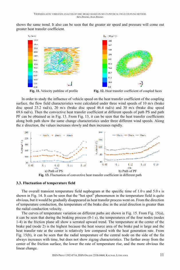
shows the same trend. It also can be seen that the greater air speed and pressure will come out greater heat transfer coefficient.
Fig. 11. Velocity pathline of profile
Fig. 12. Heat transfer coefficient of coupled faces
In order to study the influence of vehicle speed on the heat transfer coefficient of the coupling surface, the flow field characteristics were calculated under three wind speeds of 10 m/s (brake disc speed 23.2 rad/s), 20 m/s (brake disc speed 46.4 rad/s) and 30 m/s (brake disc speed 69.6 rad/s). Then the convective heat transfer coefficient at different speeds of path PS and path PF can be obtained as in Fig. 13. From Fig. 13, it can be seen that the heat transfer coefficients along both path show the same change characteristics under three different wind speeds. Along the 𝑥 direction, the values increases slowly and then increases rapidly.
a) Path of PS
b) Path of PF
Fig. 13. Fluctuation of convective heat transfer coefficient in different path
3.3. Fluctuation of temperature field
The overall transient temperature field nephogram at the specific time of 1.0 s and 5.0 s is shown in Fig. 14. It can be seen that the “hot spot” phenomenon in the temperature field is quite obvious, but it would be gradually disappeared as heat transfer process went on. From the direction of temperature conduction, the temperature of the brake disc in the axial direction is greater than the radial conduction velocity.
The curves of temperature variation on different paths are shown in Fig. 15. From Fig. 15(a), it can be seen that during the braking process (0-1 s), the temperatures of the four nodes (nodes 1-4) in the friction plane all show a serrated upward trend. The temperature at the center of the brake pad (node 2) is the highest because the heat source area of the brake pad is large and the heat transfer rate at the center is relatively low compared with the heat generation rate. From Fig. 15(b), it can be seen that the radial temperature of the central node on the side of the fin always increases with time, but does not show zigzag characteristics. The farther away from the center of the friction surface, the lower the rate of temperature rise, and the more obvious the linear change.

THERMOELASTIC VIBRATION ANALYSIS OF DISC BRAKE BASED ON MULTI-PHYSICAL FIELD COUPLING METHOD. SEN ZHANG, JIAN ZHANG
12 JOURNAL OF VIBROENGINEERING. FEBRUARY 2020, VOLUME 22, ISSUE 1
a) The time of 1.0 s
b) The time of 5.0 s
Fig. 14. Transient temperature field of disc brake
a) Path of PA
b) Path of PB
Fig. 15. Fluctuation of transient temperature in different path
3.4. Fluctuation of stress field
The overall transient stress field nephogram at the specific time of 1.0 s and 5.0 s is shown in Fig. 16. It can be seen that the “hot spot” phenomenon is more obvious, especially in initial braking stage. It is mainly caused by the fin structure, which will result in unbalancing brake pressure on the contact surface. The brake pressure on the overlapping position of the brake pad and fin is larger than both sides, and the “hot spot” phenomenon in stress field does not last long because the elastic deformation is recovered very soon.
a) The time of 1.0 s
b) The time of 5.0 s
Fig. 16. Transient stress field of disc brake
The curves of stress variation on different paths are shown in Fig. 17. From Fig. 17(a), it can be seen that the stress change in radial direction (nodes 1-4) of friction plane is consistent with the change of temperature in the braking process. The stress variation of node 5 shows more obvious fluctuation, but it remains relatively small because it is far from the friction surface. From Fig. 17(b), it can be seen that there is a significant difference between the law of stress change and the law of temperature change, especially in the braking stage. The phenomenon of stress mutation is very obvious because the brake pad has a direct compressive effect on the ribs. When the brake pad skips the joint, the stress decreases instantaneously and there is almost no time delay phenomenon.

THERMOELASTIC VIBRATION ANALYSIS OF DISC BRAKE BASED ON MULTI-PHYSICAL FIELD COUPLING METHOD. SEN ZHANG, JIAN ZHANG
ISSN PRINT 1392-8716, ISSN ONLINE 2538-8460, KAUNAS, LITHUANIA 13
a) Path of PA
b) Path of PB
Fig. 17. Fluctuation of transient stress in different path
3.5. Fluctuation of thickness size and braking torque
Within the friction radius range, the fluctuations of the average brake disc thickness and the braking moment are extracted as shown in Fig. 18 and Fig. 19, respectively. It can be seen that with the increase of braking pressure, the fluctuation value of the brake disc thickness is negative, that is, the brake disc pressure thickness is thinner than the original brake disc, and the thickness will gradually recover when leaving the brake disc, so the reciprocating motion will fluctuate. At the beginning of braking, with the increase of static braking moment caused by pedal force, the braking moment also shows an upward trend. When the static braking moment reaches its maximum and remains constant, the change trend of braking moment and braking pressure tends to be gentle, but then the braking moment shows a slow downward trend. This is because the friction coefficient between the disc and the disc decreases with the increase of temperature.
Fig. 18. Fluctuation of brake disc thickness size
Fig. 19. Fluctuation of braking torque
4. Conclusions
The thermoelastic vibration phenomenon of brake is studied by means of multi-physical field coupling in the paper. Compared with the current mainstream research methods, although the construction of the model is very complicated, its operation efficiency and accuracy are excellent. Besides, the boundary conditions are more accurate and the results are more reliable. The bench test shows that the simulation results of temperature match well with the experimental results, with only an average deviation of 3.9 %. The research method can provide quite a reliable basis for the design of brake system and NVH research. Thermoelastic vibration parameters show significant fluctuation and imbalance. For instance, the “hot spot” phenomenon in the temperature field and stress field of brake disc is quite obvious, and these node parameters in the friction radius show the trend of zigzag deformation. A great deal of heat is generated between the brake disc and the brake pad, which will cause the temperature of the brake disc surface increasing rapidly and produce annular tropical zone in the friction radius. Thermal stress will cause thermal deformation of the brake disc, and lead to fluctuations in the displacement and braking pressure of the brake pad. At the same time, the friction coefficient will change with the increase of

THERMOELASTIC VIBRATION ANALYSIS OF DISC BRAKE BASED ON MULTI-PHYSICAL FIELD COUPLING METHOD. SEN ZHANG, JIAN ZHANG
14 JOURNAL OF VIBROENGINEERING. FEBRUARY 2020, VOLUME 22, ISSUE 1
temperature, which will eventually lead to fluctuations in the thickness and braking moment of the brake disc.
Acknowledgements
The paper is supported by Doctoral Research Fund (2017Y22), National Natural Science Foundation of China (51705028) and Shandong Natural Science Foundation (ZR2016EEB36, ZR2019PEE021).
References
[1] Palmer E., Mishra R., Fieldhouse J. Analysis of air flow and heat dissipation from a high performance passenger car front brake rotor. University of Huddersfield, Vol. 215, 2006, p. 1219-1228.
[2] Zhou R. F., Feng M. X., Jiang M. Z. Research on fatigue damage of sucker rod based on damage mechanics. Applied Mechanics and Materials, Vol. 633, Issue 634, 2014, p. 1117-1123.
[3] Meng J. D., Zhang L. J., Yu Z. P. The thermal-mechanical coupling theory modeling and analysis of ventilated disc brakes. Journal of Tongji University, Vol. 6, 2010, p. 890-897.
[4] Hassan M. Z. A Predictive tool to evaluate disk brake squeal using a fully coupled thermo-mechanical finite element model. Drive System Technique, Vol. 51, 2013, p. 124-142.
[5] Belhocine A. Thermal-mechanical coupled analysis of a brake disk rotor. Journal of Failure Analysis and Prevention, Vol. 13, 2013, p. 167-176.
[6] Pei S. H., Guo X. X., Wei F. D. Sequentially coupled thermal-mechanical analysis of the brake disc used in air disc brake. Advanced Materials Research, Vol. 850, Issue 851, 2013, p. 245-248.
[7] Wang K., Tang J. Analysis of thermal-mechanical coupling of automotive disc brake based on numerical simulation method. Open Mechanical Engineering Journal, Vol. 9, 2015, p. 28-33.
[8] Zheng X. J., Luo T. H., Jia C. Dynamic response modeling of fluid-solid coupling for wet brake disc. Applied Mechanics and Materials, Vol. 475, Issue 476, 2013, p. 1397-1401.
[9] Kalashnikova I., Barone M. F., Brake M. R. A stable Galerkin reduced order model for coupled fluid-structure interaction problems. International Journal for Numerical Methods in Engineering, Vol. 95, 2013, p. 121-144.
[10] Liu D. X., Wang L. N., Han J. Selection research in automotive friction materials test equipment. Journal of Testing Technology, Vol. 3, 2016, p. 215-220.
[11] Dong J. B. Introduction of disc brake structure principle and application analysis. Scientific and Technological Innovation Herald, Vol. 20, 2011, p. 89.
[12] Dong F., Guo G. L. Diesel engine cooling water cavity structure optimization analysis based on the heat flow directly coupling method. Civil Engineering Technology, Vol. 3, 2015, p. 77-84.
[13] Chen F., Wang C. J. Review of fluid-structure coupling theory and algorithm. Space Structure, Vol. 4, 2012, p. 55-63.
[14] Cho C., Ahn S. Transient thermoelastic analysis of disk brake using the fast Fourier transform and finite element method. Thermal Stresses, Vol. 25, 2002, p. 215-220.
[15] Chakraborty S., Sen A. Adaptive response surface based efficient finite element model updating. Finite Elements in Analysis and Design, Vol. 80, 2014, p. 33-40.
[16] Zhao B. J. Study on unsteady flow characteristics in double channel pump based on slip mesh. Journal of Agricultural Engineering, Vol. 25, 2009, p. 115-119.
[17] He W. Comparison between multiple reference frame method and the sliding mesh method in numerical simulation of the auto front intake. Computer Aid Engineering, Vol. 3, 2007, p. 96-100.
[18] Duan H. J., Tao H. Influence of y+ value on aerodynamic parameters calculation accuracy of airfoil. Journal of Air Force Engineering University Natural Science Edition, Vol. 13, 2012, p. 25-29.
[19] Lu L. P. Study of theoretical dissipation rate k-epsilon model in near wall region. Journal of Engineering Thermophysics, Vol. 26, 2009, p. 434-436.
[20] Zhou J. F. Experimental and simulation research on the influence of dynamic friction coefficient to the temperature field of disc brake. Journal of Mechanical Engineering, Vol. 52, 2016, p. 150-157.
[21] Piao Zh Y., Zhou Zh Y., Xu J., Wang H. D. Use of X-ray computed tomography to investigate rolling contact cracks in plasma sprayed Fe-Cr-B-Si coating. Tribology Letters, Vol. 67, 2019, p. 11.

THERMOELASTIC VIBRATION ANALYSIS OF DISC BRAKE BASED ON MULTI-PHYSICAL FIELD COUPLING METHOD. SEN ZHANG, JIAN ZHANG
ISSN PRINT 1392-8716, ISSN ONLINE 2538-8460, KAUNAS, LITHUANIA 15
Sen Zhang is Engineering Ph.D. graduated from Shandong University of Science and Technology, Shandong, China. His current research interests include noise and vibration virtual prototype technology, friction thermodynamics, etc.
Jian Zhang is Engineering Ph.D., graduated from Yanshan University, Hebei, China. His current research interests include surface friction, vibration and impact, etc.