thermoeconomics analysis of inlet air cooling in gas turbine plants
DESCRIPTION
ThermoEconomics Analysis of Inlet Air Cooling in Gas Turbine PlantsTRANSCRIPT

Open Access Journal
Journal of Power Technologies 93 (2) (2013) 90–99journal homepage:papers.itc.pw.edu.pl
Thermo-Economic Analysis of Inlet Air Cooling In Gas Turbine Plants
Ali Marzouk∗a, Abdalla Hanafib
aUpper Egypt Electricity Production Company750 MW Korymat Power Plant, EGYPT
bFaculty of Engineering, Mechanical Power DepartmentCairo University, Giza, Egypt
Abstract
Gas turbine power plants are widely used for power generation in the world; they are low cost, quick to installand engender stability with regard to electricity grid variations. They are nevertheless negatively impactedby ambient temperature: on hot days power demand increases while gas turbine power falls. An 18% de-crease in efficiency occurs at ambient temperature 40◦C due to lower air density and the resulting increase incompressor specific work.
Inlet cooling methods are used to cool inlet air to boost the power loss on hot days. In this paper chillercooling and evaporative cooling are studied thermally and economically for a 264 MW gas turbine plantlocated at Korymat, southern Egypt. The results indicate that the annual power gained by chiller cooling is117,027 MWh, and the net cash flow is $3,787,537 while the annual power gained by evaporative cooling is86,118 MW, and the net cash flow is $4,503,548.
Keywords: Gas turbine, Inlet cooling, Power enhancement
1. Introduction
Gas turbine plants are used for electricity produc-tion in many countries around the world because oftheir low capital cost, short synchronization time of30 minutes (time required for gas turbine to reachthe base load from zero speed), stability with regardto the electricity grid and availability in many coun-tries, including in this case Egypt. Total electricitygenerated by gas turbine plants in Egypt is about7001 MW [1] from different gas turbine models andcapacities varying from 25 MW to 260 MW. On hotdays in summer, the ambient temperature reaches40◦C and the gas turbine power output decreases by
∗Corresponding authorEmail addresses: [email protected] (Ali
Marzouk∗), [email protected] (Abdalla Hanafi)
18% from rated capacity, leading to total power lostfrom gas turbine plants of about 1440 MW while theelectric load increases to maximum due to air condi-tioning and ventilation.
It is therefore necessary to enhance the achiev-able gas turbine power output by cooling the inletair. There are two main inlet cooling types: (i) evap-orative or fogging cooling, and (ii) chiller cooling—electrical or absorption.
Evaporative systems cool the inlet air by evaporat-ing water into the air stream. The water evaporationcauses the air temperature to drop. Low humidityclimates are suitable for use of this cooling technol-ogy. Two considerations must be taken into account.Firstly, the maximum relative humidity that it is pos-sible to reach with an evaporative system is just over90%. Secondly, the difference between wet and dry

Journal of Power Technologies 93 (2) (2013) 90–99
bulb temperatures in the outer section of the evapo-rative system is recommended not to be under 1◦C.
Two working fluids are used in the chiller sys-tem, the first one is the refrigerant in the refrigerationmachine which consists of a compressor,evaporator,condenser and expansion device. The refrigerant isused in this cycle to cool secondary fluid, usuallychilled water, which is pumped through an air-waterheat exchanger located at the gas turbine inlet to coolair coming into the compressor.
The chiller system has the advantage of being ableto reduce the air temperature to 5◦C, but it involvesvery high capital cost.
The first application of combustion turbine inletair cooling (CTIAC) was a direct air conditioningsystem for a plant in Battle Creek, Michigan (USA)in 1987–88, the second was an off-peak ice harvestersystem in Lincoln, Nebraska (USA) in 1992 [2].
Hall et al. [3] documented the performance of a36 MW CT plant in which a chilled water-based stor-age refrigeration system was tasked with cooling in-let air. The cooling system was able to reduce theair temperature from an ambient 35◦C to 7◦C, thusenhancing plant performance by 10%.
Zamzam and Al-Amiri [4] examined the potentialuse of employing CTIAC refrigeration systems in theUnited Arab Emirates. They used wet-bulb and dry-bulb weather data to determine characteristic designconditions of three Emirates: Al-Ain, inland arid,very hot and relatively dry; Abu Dhabi, coastal Ara-bian Gulf, very hot and humid; and Fujairah, coastalOman Gulf, hot and very humid. For given inlet airtemperatures, they determined annual gross energyincrease, average heat-rate reduction, cooling loadrequirement and net power increase. For viability,they recommended an inlet air temperature of 15–25◦C. They recommended that evaporative coolingbe used where a peak-power increase between 8%and 15% is required at high temperatures, and refrig-eration cooling where a sustainable increase of 10–25% is required.
De Lucia et al. [5] concluded that evaporativeinlet-cooling could enhance power by 2–4% a yeardepending on the weather.
An exergy,economic and environment analysiswas done [6] for a 4900 kW absorption chiller in-tegrated with a 159 MW gas turbine unit located at
0 10 20 30 40
220,000
230,000
240,000
250,000
260,000
270,000
280,000
290,000
0.358
0.36
0.362
0.364
0.366
0.368
0.37
0.372
0.374
T[1] [C]
wn
et(k
W)
effi
cien
cy
WnetWnet
thermal efficiencythermal efficiency
Figure 1: Gas turbine work and efficiency versus ambient tem-perature
Bushr-Iran. The analysis shows that the gas turbine’spower increases from 137 MW to 153 MW duringthe hottest month (August) when the inlet air wascooled from 37◦C to 15◦C. Moreover, efficiency rosefrom 33.4% to 43.2%
The present study focuses mainly on the follow-ings items, which are the specific contribution of thecurrent paper in this subject:
• Thermodynamic modeling of the Korymat gasturbine power plant in Egypt.
• Chilled water system analysis, including capac-ity calculation.
• Evaporative cooling analysis.
• Gas turbine performance parameters with andwithout cooling.
• Economic analysis for two cooling systemsbased on site conditions.
1.1. Effect of Ambient Temperature on Gas TurbineOutput Power
Gas turbine is usually designed at ISO conditionswhich meet ambient temperature and relative humid-ity of 15◦C and 60% respectively. But if the ambienttemperature increases to 40◦C in summer, gas tur-bine power deceases to 80 % rated. Fig. 1 shows gasturbine output power and thermal efficiency versusambient temperature for a 264 MW gas turbine.
— 91 —

Journal of Power Technologies 93 (2) (2013) 90–99
Figure 2: Gas turbine components
5.5 6.0 6.5 7.0 7.5 8.0-250
0
250
500
750
1,000
1,250
1,500
s [kJ/kg-K]
100
kPa
1,5
00 k
Pa
Air
T1
T2S
T3
T4S
T4T2
Figure 3: T-S diagram for gas turbine process
2. Thermo Dynamic Modeling of a Gas Tur-bine [7]
Basically, gas turbine power plants consist of fourcomponents including: the compressor, combustionchamber (CC), turbine and generator. A schematicdiagram of a simple gas turbine is shown in Fig. 2.Fresh atmospheric air is drawn into the circuit con-tinuously and energy is added by combustion of thefuel in the working fluid itself. The products of com-bustion are expanded through the turbine, which pro-duces the work and finally discharges to the atmo-sphere.
It is assumed that compressor efficiency and tur-bine efficiency are represented as ηc and ηt re-spectively. The ideal and actual processes onthe temperature-entropy diagram are represented in
black and red lines respectively, as shown in Fig. 3.The compressor compression ratio is given by
Rp =p2
p1(1)
Compressor isentropic efficiency in the range of80% to 90% is expressed as:
ηc =T2S − T1
T2 − T1(2)
So compressor exit temperature (T2) is given by:
T2 = T1 ·
(1 + Rp
γa−1γa
)(3)
Compressor work is obtained from:
Wc = Cpa · (T2 − T1) (4)
or
Wc =
Cpa · T1
(Rp
γa−1γa − 1
)ηm · ηc
(5)
Combustion chamber analysis:By applying energy balance on the combustion
chamber:
ma ·Cpa · T2 + m f · LHV =(ma + m f
)·Cpg · T3 (6)
The air to fuel ratio is expressed as
F =ma
m f(7)
The exhaust temperature of turbine (T4) is ob-tained from the relation:
T4 = T3 ·
1 − ηt ·
1 − 1
RPγg−1γg
(8)
T4 = T3 · (1 − ηt) · RPg (9)
Where RPg =
(1 − 1
RPγg−1γg
)Turbine shaft work is given by:
Wt = Cpg · (T3 − T4)Wt = Cpg · T3 · ηt ·
RPg
ηm
(10)
— 92 —

Journal of Power Technologies 93 (2) (2013) 90–99
The net work output from the gas turbine is ob-tained as:
Wnet = Wt −Wc (11)
The output power from gas turbine unit is ex-pressed as:
P (MW) =(ma + m f
)·Wnet (12)
The specific fuel consumption is given as:
s f c =360◦
Wnet(13)
The heat added to the combustion chamber is cal-culated from:
Qadd = Cpg · (T3 − T2) (14)
or
Q1add = C1pg ·[T1 3 − T1 (1) ·
(1 + RPg
)](15)
Gas turbine thermal efficiency is obtained from:
ηth =Wnet
Qadd(16)
The unit heat rate is expressed as:
HR =360◦
ηth(17)
The thermodynamic modeling of the gas turbinewith design data was solved by the (EES) Engineer-ing Equation Solver to get the calculated parametersfor the selected gas turbine.
3. Korymat Gas Turbine Power Plant
The Korymat 750 MW combined cycle powerplant consists of two gas turbine units 2×264 MWand a steam turbine with 250 MW, manufacturedby Siemens (V94.3A2), and installed and commis-sioned in 2008. The units’ operating fuels are: (i)natural gas as main fuel, the specification listed inTable 2, and (ii) liquid fuel as secondary fuel. Thereare two steam turbines 2×627 MW commissionedin 1996, and the turbine data are shown in Table 1.The design of the inlet cooling systems depends on
Table 1: Gas turbine design data
Item Rate
Gas turbine output, MW 264.344Air inlet temperature (ISO), ◦C 15Relative humidity, % 60Average air mass flow rate, kg/s 650Ambient pressure, bar 1.013Exhaust gases temperature, ◦C 586.2Exhaust gases flow rate, kg/s 666Heat rate, kJ/kWh 9435.4Gas lower heating value, kJ/kg 47040Compression ratio 15Inlet temperature to turbine, ◦C 1350Fuel gas mass flow rate, kg/s 14.59Efficiency, % 37
Table 2: Natural Gas specification [8]
CH4 C2H6 C3H8 C4H10 CO2 N2
88.1% 6.55% 2.74% 0.2% 1.89% 0.21%
the ambient conditions of the site. A cooling sys-tem designed for hot humid sites differs from onedesigned for hot and dry sites, so the weather con-ditions should be studied to determine the weatherprofile. In the present study Korymat power plantsouth of Cairo was considered, and the temperatureprofile for 2009 presented to get the average tempera-ture every month. Fig. 2 and Fig. 3 show the temper-ature and relative humidity profiles during one dayper month [9]. Fig. 4 shows the hourly ambient tem-perature through one day per month over one year,the maximum temperature in July is 35◦C, the mini-mum in Jan. is 11◦C, and the average is 23◦C.
Fig. 5 shows the relative humidity variation overthe year as per day every month, the maximum, min-imum and average are: 82%, 14% and 48% respec-tively.
4. Chiller System Inlet Cooling
In a chilled water system, water is first cooled inthe water chiller then pumped to the water coolingcoils in terminals in which air is cooled and dehumid-ified after flowing through the coils, the chilled wa-
— 93 —

Journal of Power Technologies 93 (2) (2013) 90–99
Figure 4: Hourly ambient temperature through the year
Figure 5: Hourly relative humidity through year
ter increases in temperature up to 15.6 to 18.3◦C andthen returns to the chiller. Chiller operation is basedon the refrigeration cycle and understanding this cy-cle is necessary in the refrigeration cycle, in whichair passing over the cooling coils raises the watertemperature which is circulated through the evapo-rator The air passes through the chiller coils, raisesthe temperature of the liquid refrigerant to its boilingpoint and evaporates it into a gas.
A flow diagram of the chiller system is presentedin Fig. 4. The system consists of a chiller packageunit with design capacity and chilled water pumpsare used to circulate the chilled water between thechiller unit and cooling coil. Service water pumpsare used to supply water from the River Nile to the
chiller condenser to cool the refrigerant in the re-frigeration cycle. The main compact heat exchanger(water–gas) is used for the heat exchange betweenhot air and chilled water, this heat exchanger beinglocated in the gas turbine air intake and after air filtermodules.
4.1. Chiller Sizing Optimization and Calculations
It is observed that the best efficiency is obtainedcloser to the gas turbine design temperature (15–18◦C) rather than the lowest inlet air temperatures(5–7◦C). Obviously, a lower size of cooler is requiredto obtain 15◦C than 7◦C. In addition, cash flows arehigher with small coolers than with large ones (bothmechanical or heat absorption), due to the improvedefficiency and reduced maintenance. If the economicsituation changes to one favorable to electricity pro-duction using natural gas as fuel, high-power chillers(sized to maximize improvement) will exhibit bet-ter economic behavior than lower-power ones. How-ever, lower-power coolers in a better economic trendwill increase the cash flow and enjoy better economicparameters than expected. Consequently, when en-ergy markets are uncertain, it is recommended to sizethe cooling system to approach design point ratherthan to obtain maximum power enhancements [10].
In Fig. 6 ambient air at inlet conditions (T1 =
40◦C,RH = 35%) enters the coil and the coolingprocess is 1–1’–2, while air temperature is reducedto the dew point temperature, condensation is startedand maintained until air outlet conditions reach T2 =
15◦C, RH = 100%. The coil cooling load is ex-pressed as [11];
CCL = ma
[(h2 − h1) − h f g (w1 − w2)
]kW (18)
The auxiliary power consumption by chiller auxil-iaries is represented as power consumption by chillercirculation and service water pumps. The chiller par-asitic load (power consumption by chiller is calcu-lated as [12]:
Qh = 0.7 ·CCL kW (19)
The hydraulic power of the centrifugal pump is ex-pressed as:
— 94 —

Journal of Power Technologies 93 (2) (2013) 90–99
Figure 6: Chilling cooling process
Pp =γQHη
W (20)
5. Evaporative cooling system
5.1. System DescriptionEvaporative coolers are used in gas turbine intake
air coolers and residential applications Fig. 7 showsa schematic arrangement of the main parts of a me-dia evaporative cooling system. Water is sprayed up-ward from a header pipe into the top of an invertedhalf pipe and is deflected downward onto a distribu-tion pad on top of the media. The distribution pad fa-cilitates entry of the water into the media by gravita-tional force and wets a very large surface area formedby several layers of the media. The excess water (notabsorbed by the media and not evaporated by the hotair) is collected in the bottom part of the cooler andforwarded to a reservoir tank.
Figure 7: Evaporative cooler section
Figure 8: Evaporative cooler actual process
The hot air passes through the media and evapo-rates the water up to the saturation point before enter-ing the compressor. In this process, the temperatureof the air drops by both sensible heat transfer, whichis because of the temperature differences between thewater and air, and the latent heat of evaporation [13].
Fig. 8 explains the evaporative cooling process,while the air inlet conditions at 40◦Cand RH 35%passing through cooling media which is already wet-ted with water, the air relative humidity increasesso the ambient dry bulb temperature decreases withconstant wet bulb temperature until ambient relativehumidity reaches 90%. Line 1–2 on the psychomet-ric chart represents the cooling process, and the cool-ing temperature depends on the air relative humidity,as the outlet temperature is expressed by:
— 95 —

Journal of Power Technologies 93 (2) (2013) 90–99
Ta2 = Ta1 − N · (Ta1 − Twb) ◦C (21)
Cooler effectiveness is selected to be 90%. Gasturbine output power is calculated at cooling temper-ature to estimate the annual gas turbine power gainedby cooling according to average ambient conditions,also the difference between power with and withoutcooling is calculated:
∆P = P2 − P1 (kW) (22)
The water vaporization flow rate is expressed bythe relation:
R =V (w2 − w1) ρa
ρwm3/s (23)
the blow down rate can be determined from theblow down ratio which is:
E =the blow down rateevaporation rate
=BR
(24)
This ratio will be calculated from the waterhardness—E curve. Water hardness of 150 ppm wasused for this purpose [14] and the ratio (E) was equalto 4, so the blow down rate is given by
B = 4 · R (25)
Total water consumption (Qw) is equal to the sumof the evaporation rate and blow down rate:
Qw = B + R(m3/s
)(26)
6. Economic analysis for inlet cooling systems
The basis of most design decisions is economic.Designing a system that functions properly is onlyone part of the engineer’s task. The system must alsobe economical and show an adequate return on in-vestment.
The comparative study of chiller system inlet cool-ing and evaporative cooling will use the Total An-nual Cost Method, [15] to gauge the annual cost ofalternative designs. The total annual cost generallyconsists of five terms: capital investment, fuel cost,O&M cost, electricity consumption cost and treatedwater cost. The relation is expressed by:
T AC = Ci · (AFCR) + C f + CO + CE + Cw (27)
where: T AC—Total annual cost ($/year), C f —Annual fuel cost ($/year), CO—Annual O&M cost($/year), Ci—Capital Investment ($), CE—electricityconsumption cost by system ($/year), (AFCR)—Annual Fixed Charge Rate, Cw—Treated water cost($/year).
The chiller capital investment is expressed as perevery incremental power increase as 500 $/kWh [16]while it is 50 $/kWh for evaporative cooler. TheAFCR factor is in the range of 10.5%–20% so it isselected to be 15%.
The natural gas unit price is taken as about1.25 mmBTU [17] (as per Egypt’s energy market)so the total fuel price is:
(C f ) = Cn · Qg $/year (28)
The chiller operation maintenance cost is taken as6% [18] of capital cost, and 4% for the evaporativecooler since it has smaller components.
The electric power consumption price per year isestimated based on unit price 0.07 $/kWh
CE = 0.07 ·CCL (kW) (29)
The net cash flow income per year is
(C f ,net) = CFi − T AC $ (30)
Income cash flow (CFi) is expressed as:
CFi = Ce · P($/year
)(31)
The Payback Period is the time required to recoverthe cost of an investment and is calculated as:
PB = investment/ (cash f low/year)
7. Results
In order to establish a systematic comparison be-tween the effects of the two coolers, the performanceof the gas turbine unit is examined for a restrictedset of operational and design conditions of an operat-ing GT unit, taking into account the real climatic cir-cumstances that prevailed during 2009 at Korymat,south of Cairo, Egypt. The power plant performance
— 96 —
Journal of Power Technologies 93 (2) (2013) 90–99
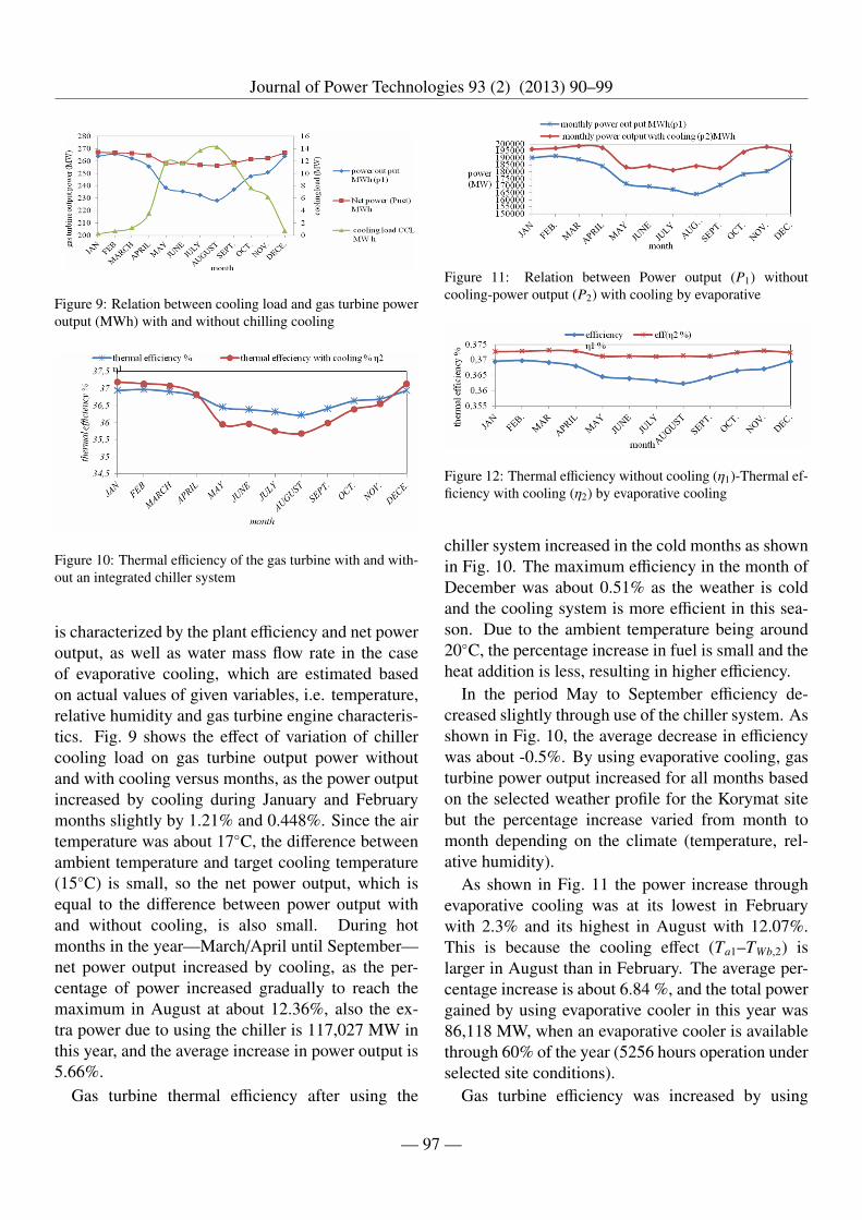
Figure 9: Relation between cooling load and gas turbine poweroutput (MWh) with and without chilling cooling
Figure 10: Thermal efficiency of the gas turbine with and with-out an integrated chiller system
is characterized by the plant efficiency and net poweroutput, as well as water mass flow rate in the caseof evaporative cooling, which are estimated basedon actual values of given variables, i.e. temperature,relative humidity and gas turbine engine characteris-tics. Fig. 9 shows the effect of variation of chillercooling load on gas turbine output power withoutand with cooling versus months, as the power outputincreased by cooling during January and Februarymonths slightly by 1.21% and 0.448%. Since the airtemperature was about 17◦C, the difference betweenambient temperature and target cooling temperature(15◦C) is small, so the net power output, which isequal to the difference between power output withand without cooling, is also small. During hotmonths in the year—March/April until September—net power output increased by cooling, as the per-centage of power increased gradually to reach themaximum in August at about 12.36%, also the ex-tra power due to using the chiller is 117,027 MW inthis year, and the average increase in power output is5.66%.
Gas turbine thermal efficiency after using the
Figure 11: Relation between Power output (P1) withoutcooling-power output (P2) with cooling by evaporative
Figure 12: Thermal efficiency without cooling (η1)-Thermal ef-ficiency with cooling (η2) by evaporative cooling
chiller system increased in the cold months as shownin Fig. 10. The maximum efficiency in the month ofDecember was about 0.51% as the weather is coldand the cooling system is more efficient in this sea-son. Due to the ambient temperature being around20◦C, the percentage increase in fuel is small and theheat addition is less, resulting in higher efficiency.
In the period May to September efficiency de-creased slightly through use of the chiller system. Asshown in Fig. 10, the average decrease in efficiencywas about -0.5%. By using evaporative cooling, gasturbine power output increased for all months basedon the selected weather profile for the Korymat sitebut the percentage increase varied from month tomonth depending on the climate (temperature, rel-ative humidity).
As shown in Fig. 11 the power increase throughevaporative cooling was at its lowest in Februarywith 2.3% and its highest in August with 12.07%.This is because the cooling effect (Ta1–TWb,2) islarger in August than in February. The average per-centage increase is about 6.84 %, and the total powergained by using evaporative cooler in this year was86,118 MW, when an evaporative cooler is availablethrough 60% of the year (5256 hours operation underselected site conditions).
Gas turbine efficiency was increased by using
— 97 —

Journal of Power Technologies 93 (2) (2013) 90–99
Figure 13: Total annual cost for chiller and evaporative cooling
Figure 14: Net cash flow for chiller and evaporative cooling
evaporative inlet cooling as shown in Fig. 12. Themaximum percentage increase was in August, at2.4%, the minimum increase in December, at 0.79%,but this also depends on the cooling effect, as the av-erage increase is 1.54%. Efficiency gives a good in-dication for specific fuel consumption.
Fig. 13 shows the total annual cost for chiller andevaporative cooler systems. It is noted that the annualcost for the chiller is higher than for the evaporativecooler, because the electricity consumption for thechiller is very high and the capital cost is also higher.
Fig. 14 indicates the net cash flow from electric-ity sales when the gas turbine is integrated with twocooling systems. It shows that the net cash flow ishigher in the case of cooling by an evaporative coolerbecause the total annual cost of the chiller is higherdue to its higher power consumption.
8. Conclusion
From the present study for gas turbine plant with264 MW located at Korymat power plant, in south-east Egypt for selected weather data and after study-
ing the effect of two inlet cooling technologies tocool inlet air for enhancement of gas turbine powerloss at the summer peak, we can conclude that thetotal yearly gas turbine output power gained dueto cooling by the chiller system is 117,027 MWh,the annual cost is $7,624,548.90 and the net cashflow from the plant is $3,787,587 and the paybackperiod is 3.3 years. While the yearly gas turbinepower gained due to using evaporative cooling is86,118 MWh, the total annual cost is $1,524,779.70,the net cash flow is $4,503,548.50, and the paybackperiod is 0.66 year. Average gas turbine thermal ef-ficiency of the plant in the case of using the chillerwas 36.46% while with evaporative cooling it was37.205%.
The evaporative cooler is effective for cooling inletair for a gas turbine, it is more economical, has lowmaintenance and low electricity consumption, wateris available from the River Nile and the capital costis low.
Other cooling technologies may be studied for gasturbines, such as absorption cooling, a fogging sys-tem and compressor inter cooling.
References
[1] Annual report, Tech. rep., Egyptian Electricity HoldingCompany, pp 1–15, Egypt (2009/2010).
[2] C. D. MacCracken, Overview of the progress and the po-tential of thermal storage in off-peak turbine inlet cooling,ASHRAE Transactions 100 (1994) 569–571.
[3] A. D. Hall, el al., Gas turbine inlet-air chilling at a co-generation facility, transactions of the American Societyof Heating Refrigerating and Air Conditioning Engineers100 (1994) 595–600.
[4] M. M. Zamzam, A. M. Al-Amiri, Feasibility of combus-tion turbine inlet air cooling in the arabian gulf region,in: Proceedings of the international joint power genera-tion conference, Scottsdale, Arizona, USA, 2002, pp. 35–39.
[5] M. De Lucia, et al., Benefits of compressor inlet aircooling for gas-turbine cogeneration plants, in: Proceed-ings Of The International Gas Turbine And AeroengineCongress And Exposition, Houston Texas, 1995.
[6] M. A. Ehyaei, S. Hakimzadeh, N. Enadi, P. Ahmadi, Ex-ergy, economic and environment (3e) analysis of absorp-tion chiller inlet air cooler used in gas turbine powerplants, International Journal of Energy Research 36 (4)(2012) 486–498.
[7] M. M. Rahman, et al., Thermodynamic performance anal-ysis of gas-turbine power-plant, International Journal ofthe Physical Sciences 6 (14) (2011) 3539–3550.
— 98 —

Journal of Power Technologies 93 (2) (2013) 90–99
[8] UEEPC, Elkorymat 750 MW combined cycle contract,Combustion turbine technical specification, 10042-9-3PS-MUTC-00001, Vol. 3AOF4, Egypt (2006).
[9] Weather underground conditions history of climate con-ditions in 2009, Cairo, Egypt, www.wunderground.com.
[10] R. Garetaet, et al., Methodology For The Economic Eval-uation Of Gas Turbine Air-Cooling Systems In CombinedCycle Applications, University Of Zaragoza, Centro Po-litecnico Superior, Maria De Luna, 3, 50015 Zaragoza,Spain.
[11] S. Boonnasaa, et al., Performance Improvement Of TheCombined Cycle Power Plant By Intake Air Cooling Us-ing An Absorption Chiller, A department Of Energy Tech-nology, King Mongkut’s University Of Technology Thon-buri, Thungkhru, Bangkok 10140, Thailand, 2004.
[12] ASHRAE Handbook–HVAC Systems And Equipment(SI), 2008, Ch. 17, Combustion turbine inlet cooling, p.17.2.
[13] GE Energy, Operation And Maintenance Recommenda-tions For Media Type Gas Turbine Inlet Air EvaporativeCoolers. pp 8, gek 111331a revised Edition (November2009).
[14] GE Energy, Water Supply Requirement For Gas TurbineInlet Air Evaporative Coolers, pp 29, gek 107158a, re-vised Edition (January 2002).
[15] M. S. Mohammed, Thermo-Economic Analysis Of Helio-stat System Integrated With Multi Stage Flash Unit, Fac-ulty Of Engineering, Cairo University, Egypt, 2011.
[16] M. Abdulrahman, V. Abdulhadi, A review of inlet air-cooling technologies for enhancing the performance ofcombustion turbines in Saudi Arabia, Energy Research In-stitute, King Abdulaziz City for Science and Technology,P.O. Box 6086, Riyadh 11442, Saudi Arabia.
[17] Ministry of petroleum web site, Natural gas price forheavy industries, Egypt, 2012, www.petroleum.gov.eg.
[18] S. Boonnasaa, et al., Performance Improvement Of TheCombined Cycle Power Plant By Intake Air Cooling Us-ing An Absorption Chiller, A department Of Energy Tech-nology, King Mongkut’s University Of Technology Thon-buri, Thungkhru, Bangkok 10140, Thailand, 2004.
Nomenclature
∆P Difference Between Gas Turbine Output (With-out And With Cooling), MW
ma1 Air Mass Flow Rate At Inlet Of Cooler, kg/s
m f 1 Fuel Mass Flow Rate Without Cooling, kg/s
η2 Gas Turbine Efficiency With Cooling,
ρa Air Density, kg/m3
ρw Water Density, kg/m3
B Blow Down Rate, m3/s
CCL Chiller Cooling Load, kW
E Blow Down Ratio
h1 Ambient Air Enthalpy At Cooler Inlet,kJ/(kg·K)
h2 Ambient Air Enthalpy At Cooler Outlet,kJ/(kg·K)
LHV Lower Heating Value For Natural Gas, kJ/kg
N Evaporative Cooler Efficiency,
P Gas Turbine Power Out Put, MW
P2 Gas Turbine Power Output With Cooling, MW
P1 Gas Turbine Power Output Without Cooling,MW
Qadd Heat Added To Combustion Chamber,kJ/(kg·K)
Qh Chiller Parasitic Load, kW
R Evaporative Cooler Vaporization Rate
Ta,1 Ambient Air Temperature At Inlet, ◦C
Ta,2 Ambient Air Temperature At Outlet, ◦C
Twb,2 Wet Bulb Temperature Of Outlet Air, ◦C
V Air Volume Flow Rate, m3/s
w1 Humidity Ratio Of Air At Cooler Inlet, gm/kg
w2 Humidity Ratio Of Air At Cooler Outlet, gm/kg
— 99 —