thermodynamic performance investigation of gas…data.conferenceworld.in/icrismet/p541-553.pdf ·...
TRANSCRIPT
541 | P a g e
THERMODYNAMIC PERFORMANCE
INVESTIGATION OF GAS/STEAM COMBINED
CYCLE BASED ON EXERGY ANALYSIS
Shivam Mishra1, Mithilesh Kumar Sahu
2, Sanjay
3
1,2Ph.D. Scholar, Mechanical Engg. Department, Nit, Jamshedpur, (India)
3Professor, Mechanical Engg. Department, Nit, Jamshedpur, (India)
ABSTRACT
In the era of high energy demand gas turbine based combined cycle power plant (CCPP) has a critical role in
power generation. Present paper deals with the thermodynamic performance investigation of gas/steam
combined cycle on the basis of exergy analysis. The gas turbine cycle was taken as higher-temperature topping
cycle and steam power cycle was embraced as lower temperature bottoming cycle. In this paper, the second law
examination of combined cycle power plant with single pressure HRSG has been accounted for. This work plans
to determine component-wise exergetic proficiency, the reasons for exergy demolition in the significant cycle
component and to recognize the explanations behind the component-wise inefficiencies. The component wise
exergy analysis of a conceptual power plant cycle operating under a pressure ratio of 23 and turbine inlet
temperature (1700K) is carried out with a prime objective to highlight the major sites of exergy destruction in
the cycle. The work generated by gas turbine is 521.36kJ/kg while for steam turbine it is 184.79kJ/kg. The
performance of cycle on the basis of second law efficiency was assessed to be 52.45%.
Keywords: Combined Cycle, Exergy Analysis, Exergy Destruction, HRSG, Irreversibility, Gas
Turbine, Steam Turbine.
I. INTRODUCTION
Optimization of power generation system is one of the major concerns in the energy engineering field. The
increase in the prices of energy is making it important to utilize the energy up to its maximum extent [1]. Gas
turbine power plant (GTPP) is advantageous over steam cycle power plants with respect to relatively low capital
investment, lesser installation time, high reliability without complexity, quick starting as well as eco-friendly.
Besides all the advantages, gas turbine based power plants have the potential of being integrated into the steam
turbine cycle by utilizing the thermal energy of the exhaust of the gas turbine. Gas/steam based combined cycle
power plants (CCPP) offers high thermal efficiencies and improved power output. In the proposed combined
cycle there is a topping cycle, a heat recovery steam generator and a bottoming cycle. The topping cycle is the
Brayton cycle and bottoming cycle is Rankine cycle. The purpose of HRSG is to integrate topping and
bottoming cycle for their synergetic operation. The heat leaving gas turbine exhaust is utilized in HRSG. The
energy analysis of any energy system does not lead to the analysis of qualitative losses which occur in

542 | P a g e
individual components of the system. The exergy-based analysis is a promising tool to analyze any energy based
system. It also highlights the inefficiency of any energy based system. On the other hand, the second law
analysis deals with the qualitative study of energy and determines the maximum amount of theoretical useful
work obtained till the system comes to a dead state with reference to a specified environment. Exergy analysis
focuses on the destruction of available energy in contrast to energy analysis which focuses on conservation of
energy. Second law analysis determines the component level irreversibility and also the magnitude of
irreversibility. The second law efficiency of CCPP is generally less than first law efficiency [2].
Several researchers have studied various aspects of combined cycle power plant and second law analysis of
different energy based systems. A literature review of CCPP and exergy analysis is discussed below. M. J.
Javadi et al. [3] carried out the first law analysis of the 116 MW gas turbine power plant in Iran, and also
investigated the component-wise exergy analysis. E. Bilgen [4] carried out the exergy and energy analysis of the
cogeneration power plant. He also developed an algorithm and the results shows good agreement with the
previously reported data. A Vidal et al [5] investigated the exergy analysis of a new proposed combined power
cycle integrated with refrigeration cycle. To investigate the effect of various parameters on the new cycle in
various operating conditions, second irreversible case was analyzed. Sanjay et al [6] performed a parametric first
and second law analysis of gas-steam reheat combined cycle using closed-loop-steam-cooling. The author
suggests that steam cooling has the better cooling effects w.r.t air film cooling technique. M. Ameri et al [7]
carried out the exergy efficiency of a 420MW NEKA CCPP in Tehran, Iran. The author suggests that
combustion chamber is the main source of irreversibility followed by a gas turbine, duct burner, and HRSG.
NEKA CCPP showed exergy efficiency of 47.5% and 44% with and without duct burner. Y. Hesli et al [8]
studied the exergetic performance of a conventional recuperated GTPP integrated with the high temperature
solid oxide fuel cell.. The result highlights that increase in TIT has the adverse effect of the exergetic efficiency
as it declines with increase in TIT. Abdul Khaliq [9] investigated the second law analysis of a proposed
trigeneration system based on conventional GT for high temperature heat addition while HRSG and vapour
refrigeration systems were adopted for process heating and cold production respectively. Isam H. Aljundi [10]
carried out the exergy and energy analysis of a steam power plant in Jordan. The basic objective of that study
was to highlight the component wise quantitative exergy destruction. The percentage of exergy destruction was
the maximum in the boiler, followed by the condenser and others. Young Sik Kim et al [11] carried out a trial to
modify the compressor and gas turbine units to avoid the surge margin and overheating of blading in GT of an
IGCC as its real operating condition is changed when integrated with gasifier and air separation unit (ASU)
both. The author quoted the result that there is an increase in terms of both power output and efficiency when
both turbine and compressor modifications are enabled. O. Singh and Kaushik [2] calculated the second law
analysis of combined triple power cycles. The simulations of natural gas fired CCPP situated in India and
KALINA cycle of Iceland were done in MATLAB and then results were compared and a possibility of
KALINA cycle in Indian operating condition were investigated and effect of various parameters were also
analysed . Sanjay and B. N. Prasad [12] carried out first and second law analysis of inter-cooled combustion
turbine based CCPP and an effort has been taken for the maximization of efficiency by selecting an appropriate
pressure ratio. The author states that intercooling increase the output of around 20% . M. Ghazikhani et al [13]
carried out the second law analysis of GT with air bottoming cycle (ABC) and results were compared with

543 | P a g e
conventional GT. The prime focus of the study was the investigation of work output, specific fuel consumption
and exergy destruction. A. K. Mohapatra and Sanjay [14] carried out the parametric study of the effect of
different operating parameters such as TIT, combustor inlet temperature (CIT), pressure ratio on a cooled gas
turbine power plant with two inlet air cooling techniques. The author describes the effect of integration of two
techniques positively on plant performance. M. A. Rosen [15] deal with Second law analysis approach and its
implications on different power plant units. Nitul and Sanjay [16] have performed the exergy analysis to
investigate the effect of compression ratio and air fuel ratio on rational efficiency for a combined cycle. The
result shows that higher compression ratio and lower air/fuel ratio leads to lower exergy destruction.
II. CYCLE DESCRIPTION
Fig. 1 illustrates the proposed cycle configuration under investigation. The diagram outlines the configuration of
basic gas turbine cycle integrated with single pressure HRSG steam turbine cycle. This configuration as a whole
is known as combined cycle with single pressure HRSG. Air is taken from the atmosphere at an ambient
condition which enters to air compressor (AC), which in turn compresses air to a higher pressure level. The
compressed air which exits the air compressor enters the combustion chamber, where the burning of natural gas
in the presence of air takes place, which in succession increase its temperature and energy level. Thereafter the
expansion of pressurized high temperature flue gases takes place in a gas turbine. The HRSG is installed for the
recovery of heat content in gas turbine exhaust for steam generation purpose. Here single pressure HRSG is
being used. HRSG is generally equipped with an economiser, evaporator and super heater. Water from the
deaerator when passes through the HRSG unit, the steam of required pressure level and quality is obtained. In
HRSG unit deaerated water enters the economiser by passing through boiler feed pump, where sensible heating
of the feed water takes place as heat is added in the economiser at constant pressure. Then this sensibly heated
water is passed through the evaporator where heat added at constant evaporator pressure is just used for the
conversion of water into steam. After the phase change of the water, steam produced is then passed through the
superheater for the further temperature rise and then superheated steam is expanded in a steam turbine for the
power generation purpose. The expanded steam is then passed through the condenser where by phase change the
steam is converted into liquid phase i.e. water. The condensate extraction pump (CEP) then supply this water to
the deaerator unit where de oxidation of feed water takes place using bled steam from a steam turbine.
III. MATHEMATICAL MODELLING
Mathematical modeling of various components of the proposed cycle to evaluate its thermodynamic
performance has been detailed in the sub-sections as below.
3.1 Air Model
Air is taken as a working fluid of the cycle in the compressor. The thermodynamic properties of air enthalpy,
entropy and exergy have been mathematically modeled as under:
Thus, the enthalpy, entropy and exergy of the flue gas and air can be calculated as under:
.. (1)

544 | P a g e
...... (2)
....... (3)
Figure 1 Schematic diagram of combined cycle power plant with single pressure HRSG
3.2 Air Compressor (AC)
Working fluid air enters to the axial flow compressor at ambient conditions. The compressor compresses the air
to a higher pressure level simultaneously raising its temperature and energy level. The pressure and temperature
of the air at the exit of air compressor are determined by the following equations.
... (4)
..... (5)
Exergy loss in the compressor for 1 kg of air is
.. (6)
.... (7)
3.2Combustion Chamber (CC)

545 | P a g e
The combustion chamber experiences various types of losses which are taken care by adopting a pressure loss of
around 2% of the entry pressure at its exit and combustion chamber inefficiency of 0.5 %. Natural gas has been
taken as a fuel and is burnt in the presence of compressed air to raise its temperature. The combustion products
at high temperature lead into the gas turbine where expansion of gases takes place. Mass and energy balance
equations for combustion chamber are as mentioned below:-
...... (8)
.... (9)
Mass flow rate of fuel required has been calculated using mass and energy balance of the combustion chamber
for 1 kg of air:
..... (10)
The exergy of fuel
...... (11)
Exergy loss in combustion chamber is
.... (12)
Where
...... (13)
3.4 Gas Turbine (GT)
This high pressure and temperature flue gases sequentially expand in the stages of axial flow gas turbine, thus
power is developed by the continuous removal of energy content from the flue gases.
.... (14)
Where
..... (15)
Where
..... (16)

546 | P a g e
.... (17)
.... (18)
HRSG
The heat recovery steam generator (HRSG) is generally used for the recovery of energy from the high
temperature gas turbine exhaust. The unit generally contains an economiser, an evaporator and super heater. The
deaerated water enters the HRSG unit and exits as a superheated steam.
The energy and exergy balance equations are given as under:-
Here, h5= 3440, hf10 (Deaerator outlet) = 504.8 kJ/kg
Energy balance yields
.... (19)
The exergy loss in HRSG is given by
..... (20)
.... (21)
3.5 Exhaust
The exhaust gas exergy loss is given by
.. (22)
3.6 Steam turbine
The superheated steam from the HRSG enters the steam turbine where the continuous expansion of steam takes
place for work extraction.
The exergy loss in steam turbine is given by
..... (23)
.... (24)
Here can be calculated from energy balance of the deaerator
...... (25)
3.7 Condenser
The condenser is generally a cross flow heat exchanger which is employed to remove the heat content of the
exhaust steam from the steam turbine so as to condense it and achieve vacuum pressure for enhanced expansion
of steam in the steam turbine.
Energy balance at condenser is given by
...... (26)
547 | P a g e
... (27)
Feed Pump
The purpose of installing feed pump is to pressurise the deaerated water at deaerator pressure to the boiler
pressure. It consumes a negligible amount of work compared to the net work output.
The exergy loss in feed pump is given by
..... (28)
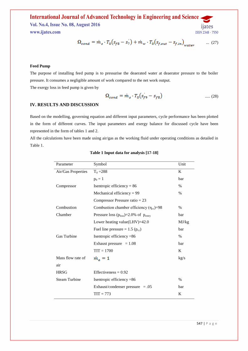
IV. RESULTS AND DISCUSSION
Based on the modelling, governing equation and different input parameters, cycle performance has been plotted
in the form of different curves. The input parameters and exergy balance for discussed cycle have been
represented in the form of tables 1 and 2.
All the calculations have been made using air/gas as the working fluid under operating conditions as detailed in
Table 1.
Table 1 Input data for analysis [17-18]
Parameter Symbol Unit
Air/Gas Properties T0 =288 K
p0 = 1 bar
Compressor Isentropic efficiency = 86 %
Mechanical efficiency = 99 %
Compressor Pressure ratio = 23
Combustion
Chamber
Combustion chamber efficiency (ηcc)=98 %
Pressure loss (ploss)=2.0% of pentry bar
Lower heating value(LHV)=42.0 MJ/kg
Fuel line pressure = 1.5 (pcc) bar
Gas Turbine Isentropic efficiency =86 %
Exhaust pressure = 1.08 bar
TIT = 1700 K
Mass flow rate of
air
kg/s
HRSG Effectiveness = 0.92
Steam Turbine Isentropic efficiency =86 %
Exhaust/condenser pressure = .05 bar
TIT = 773 K
548 | P a g e
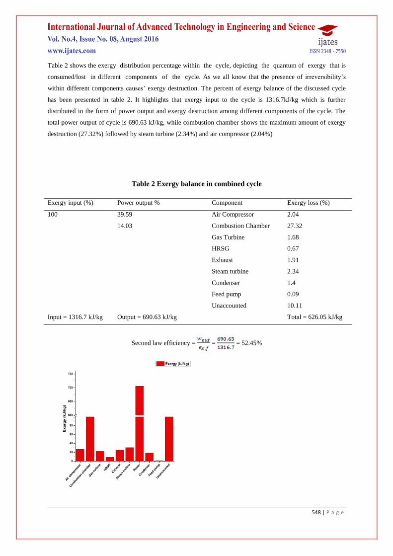
Table 2 shows the exergy distribution percentage within the cycle, depicting the quantum of exergy that is
consumed/lost in different components of the cycle. As we all know that the presence of irreversibility’s
within different components causes’ exergy destruction. The percent of exergy balance of the discussed cycle
has been presented in table 2. It highlights that exergy input to the cycle is 1316.7kJ/kg which is further
distributed in the form of power output and exergy destruction among different components of the cycle. The
total power output of cycle is 690.63 kJ/kg, while combustion chamber shows the maximum amount of exergy
destruction (27.32%) followed by steam turbine (2.34%) and air compressor (2.04%)
Table 2 Exergy balance in combined cycle
Exergy input (%) Power output % Component Exergy loss (%)
100 39.59 Air Compressor 2.04
14.03 Combustion Chamber 27.32
Gas Turbine 1.68
HRSG 0.67
Exhaust 1.91
Steam turbine 2.34
Condenser 1.4
Feed pump 0.09
Unaccounted 10.11
Input = 1316.7 kJ/kg Output = 690.63 kJ/kg Total = 626.05 kJ/kg
Second law efficiency = = = 52.45%

549 | P a g e
Figure 2 Component-Wise Exergy Distribution (Gain/Loss) Of Combined Cycle Power Plant
Figure 3 Component-wise exergy efficiency of combined cycle power plant
Figure 4 Energy And Exergy Efficiency of Gas Turbine Cycle and Combined Cycle

550 | P a g e
Figure 5 Net power output Vs cycle output
Figure 2 diagrams the component-wise rate exergy destruction in the combined cycle. It is clear from the graph
that the exergy destruction is found the most extreme in the combustion unit which demonstrates great
concurrence with the past works, additionally it is supported from the thermodynamic perspective that exergy
destruction in the combustion chamber is observed to be 25%-30%, which for our situation it is around
359.5kJ/kg (27.32%). The following most astounding exergy annihilation is in a steam turbine (2.34%), trailed
by an air compressor (2.04%).The unaccounted exergy destruction is around one-tenth (10.11%) of the
aggregate cycle exergy destruction.
Figure 3 expresses the component-wise exergetic efficiency of combined cycle power plant. The exergetic
efficiency is characterized as the proportion of exergy recovered to the exergy supplied, which further clarifies
the greatest measure of work which can be acquired when the system comes in equilibrium with environment.
The outcome demonstrates that exergy efficiency of the gas turbine is around 97.84% which portrays a
magnificent work change rate, trailed via air compressor (94.5%), steam turbine (92.1%), HRSG (79.52%) and
combustion chamber (77.3%) separately.
Figure 4 explains the comparative study of variation of exergy and energy efficiency of both combined cycle
power plant and gas turbine cycle. It can be obviously concluded from the above graph that energy and exergy
efficiency of the gas turbine cycle is 41.37% and 39.59% respectively, while for combined cycle it is 54.81%
and 52.45% respectively. This shows the good agreement for the better performance of combined cycle over
basic gas turbine cycle.
Figure 5 represents the comparison of the net power output of gas turbine and steam turbine cycles individually.
It is clear from the plot that net power output of gas turbine cycle is 521.36 kJ/kg while for steam cycle it is
169.27 kJ/kg, which explains that the power output of the gas turbine is almost three times the steam cycle and
represents the sizing ratio of these machines.
V. CONCLUSION
Based on the comprehensive thermodynamic analysis of combined cycle with single pressure HRSG, the
following conclusions have been drawn:

551 | P a g e
The component level thermodynamic analysis suggests that losses arise due to irreversibility’s within the
components of the cycle.
The energy efficiency for gas turbine and combined cycle has been observed as (41.37%) and (54.81%)
respectively.
The second law efficiency for gas turbine and combined cycle was found to be (39.59%) and (52.45%)
respectively.
The gas turbine cycle power output was observed as 521.36kJ/kg while for steam turbine cycle it was
184.79kJ/kg. The total power output for combined cycle was 690.63kJ/kg.
Exergy destruction arising due to component irreversibility’s is maximum in the combustion chamber at
27.32% followed by air compressor and exhaust gas stream at 2.04% and 1.91% respectively.
REFERENCES
[1]. Goktun S., Yavuz H., Thermal efficiency of a regenerative Brayton cycle with isothermal heat addition,
Energy Conversion Management, 40, 1999, 1259-1266.
[2]. Omendra Kumar Singh, Subhash C. Kaushik., Reducing CO2 emission and improving exergy based
performance of natural gas-fired combined cycle power plants by coupling Kalina cycle, Energy, 55, 2013,
1002-1013.
[3]. Mohamad Javad Ebadi and Mofid Gorji-Bandpy., Exergetic analysis of gas turbine plants, International
Journal of Exergy, 2(1), 2005, 31-39.
[4]. E. Bilgen., Exergetic and engineering analyses of gas turbine based cogeneration systems, Energy, 25,
2000, 1215–1229.
[5]. A.Vidal., Analysis of a combined power and refrigeration cycle by the exergy method, Energy, 31, 2006,
3401–3414.
[6]. Y. Sanjay, Onkar Singh, B.N. Prasad., Energy and exergy analysis of steam cooled reheat gas–steam
combined cycle, Applied Thermal Engineering, 27, 2007, 2779–2790.
[7]. M. Ameri. Ahmadi and S. Khanmohammadi., Exergy analysis of a 420MW combined cycle power plant,
International Journal of Energy Research, 32, 2008, 175–183.
[8]. Y Hesli, I. Dincer, G. F. Naterer., Thermodynamic analysis of a combine gas turbine power system with a
solid oxide fuel cell through exergy, Thermochimica Acta, 480, 2008, 1-9.
[9]. Abdul Khaliq., Exergy analysis of gas turbine trigeneration system for combined production of power heat
and refrigeration, International journal of refrigeration, 32, 2009, 534 – 545.
[10]. Isam H. Aljundi., Energy and exergy analysis of a steam power plant in Jordan, Applied Thermal
Engineering, 29, 2009, 324–328.
[11]. Young Sik Kim, Sung Ku Park, Jong Jun Lee, Do Won Kang, Tong Seop Kim., Analysis of the impact of
gas turbine modifications in integrated gasification combined cycle power plants, Energy, 55, 2013, 977-
986.
[12]. Sanjay, Bishwa N. Prasad., Energy and exergy analysis of intercooled combustion-turbine based
combined cycle power plant, Energy, 59, 2013, 277—284.

552 | P a g e
[13]. M. Ghazikhani a, I. Khazaee, E. Abdekhodaie., Exergy analysis of gas turbine with air bottoming cycle,
Energy, 72, 2014, 599-607.
[14]. Alok Ku. Mohapatra, Sanjay., Comparative analysis of inlet air cooling techniques integrated to cooled gas
turbine plant, Journal of the Energy Institute, xx, 2014,1-15.
[15]. M. A. Rosen., Second law analysis: approach and implications, International Journal of Energy Research,
23 (5), 1999, 415–429.
[16]. Nitul Kumar and Sanjay., Exergy analysis of effect of air/fuel ratio and compression ratio on rational
efficiency of gas/steam combined cycle, Journal of the Energy Institute, 86(1), 2013, 1-8
[17]. Sanjay, Onkar Singh, B.N. Prasad., Comparative Performance Analysis of Cogeneration Gas Turbine
Cycle for Different Blade Cooling Means, International Journal of Thermal Sciences, 48(7), 2009, 1432-
1440.
[18]. Sanjay, Onkar Singh, B.N. Prasad. Comparative evaluation of gas turbine power plant performance for
different blade cooling means, Proceedings of Institution of Mechanical Engineers, Part A: Journal of
Power and Energy, 223(1), 2009, 71-82.
[19]. Dr. R Yadav, Steam & Gas turbines and Power plant engineering, 7th
Revised and Enlarged edition 2004,
Allahabad.
[20]. P. K. Nag, Engineering Thermodynamics, 4th
edition 2008.
[21]. Yunus A. Cengel, Michael A. Boles, Thermodynamics: An Engineering Approach, 5th
edition 2006.
[22]. P.P. Walsh, P.Fletcher, Gas Turbine Performance, 2nd
edition 2004.
Nomenclature
cp Specific heat at constant pressure (kJ/kgK)
EX,H Total exergy supplied (kW)
ex Specific exergy of the stream (kJ/kg)
h Specific enthalpy of the stream (kJ/kg)
Mass flow rate (kg/s)
p Pressure (bar)
p0 Reference or ambient pressure (kpa)
Q Heat transfer rate (kW)
s Specific entropy (kJ/kgK)
S Entropy (kJ/K)
Sgen Entropy generation (kJ/K)
T Temperature (K)
T0 Reference or ambient temperature (K)
W Work (kW)
Subscripts
a Air
c Compressor
comb Combustion chamber

553 | P a g e
d Destruction
ex Exergy
f Fuel
Gen Generation
G Gas
in Inlet
Out Outlet
sat Saturated
T Turbine
w Water
Ι First law
ΙΙ Second law
1, 2, 3 State points
Greek symbols
φ Thermodynamic property function
ε Effectiveness
η
Efficiency
ω Availability per unit mass of gas
Ωd Exergy destruction rate
Acronyms
A Alternator
ABC Air bottoming cycle
AC Air compressor
ATR Auto thermal reformer
ASU Air separation unit
BGT Brayton gas turbine cycle
BFP Boiler feed pump
C Compressor
CEP Condensate extraction pump
CC Combustion chamber
CCPP Combined cycle power plant
CIT Combustor inlet temperature
GTPP Gas turbine power plant
GT Gas turbine
HRSG Heat recovery steam generator
I Irreversibility
IGCC Integrated gas combined cycle
TIT Turbine inlet temperature