thermodynamic analysis of an electrochemical refrigeration ... · thermodynamic analysis of an...
TRANSCRIPT

Thermodynamic Analysis of an Electrochemical Refrigeration Cycle
ACRCTR-1l2
For additional information:
Air Conditioning and Refrigeration Center University of Illinois Mechanical & Industrial Engineering Dept. 1206 West Green Street Urbana,IL 61801
(217) 333-3115
T. A. Newell
February 1997

The Air Conditioning and Refrigeration Center was founded in 1988 with a grant from the estate of Richard W. Kritzer, the founder of Peerless of America Inc. A State of Illinois Technology Challenge Grant helped build the laboratory facilities. The ACRC receives continuing supportfrom the Richard W. Kritzer Endowment and the National Science Foundation. The following organizations have also become sponsors of the Center.
Amana Refrigeration, mc. Brazeway, Inc. Carrier Corporation Caterpillar, Inc. Copeland Corporation Dayton Thennal Products Delphi Harrison Thennal Systems Eaton Corporation Ford Motor Company Frigidaire Company General Electric Company Hydro Aluminum Adrian, mc. Lennox mtemational, mc. Modine Manufacturing Co. Peerless of America, mc. Redwood Microsystems, mc. The Trane Company Whirlpool Corporation
For additional information:
Air Conditioning & Refrigeration Center Mechanical & Industrial Engineering Dept. University of Illinois 1206 West Green Street Urbana IL 61801
2173333115

ABSTRACT
Thermodynamic Analysis of an Electrochemical Refrigeration Cycle
Ty A. Newell
The coupling of a water-based electrochemical cell and fuel cell are discussed as a means to
form a refrigeration cycle. In the proposed configuration, the process fluids can be passively
driven through the flow circuits. The cycle requires low direct current voltages for driving the
cycle. Current densities must be maintained sufficiently low in the electrochemical cell in order to
operate below neutral voltage levels. Overall, the cycle's operational limit for the configuration
described is close to Carnot efficiency.
INTRODUCTION
A fuel cell and its reversible analog, the electrochemical cell, can be coupled in a manner that
forms some interesting thermodynamic cycles. A simple thermodynamic analysis of a
configuration for a refrigeration cycle is described in this paper. Alternative configurations can
also be developed for achieving refrigeration effects and for forming thermally driven power
cycles.
Fuel cells and electrochemical cells have a long history in science and in application (Soo
(1968)). Industrial electrochemical processes are responsible for the production of many materials.
Research in the fuel cell area continues to grow with significant demonstrations of the technology
showing its future potential (Appleby and Foulkes (1989)). Thermodynamic processes are
understood and basic fuel cell analyses commonly appear in thermodynamic textbooks (e.g.,
Moran and Shapiro(1995), Howell and Buckius (1992)). Several areas of difficulties related to
materials, transport processes and cost must be addressed in order to determine whether a practical
system of the type described could be developed. Ohta (1979) and Casper (1978) discuss many
fuel cell and electrochemical performance issues.
CYCLE DESCRIPTION
Figure 1 is a schematic of the proposed cycle. Four primary components make up the
system. An electrochemical cell is the heat absorber, equivalent to an evaporator in a conventional
vapor compression refrigeration system. A fuel cell rejects heat in a manner similar to a condenser
in a common vapor compression refrigeration cycle. The third component is a heat exchanger
between gas streams and water flow stream. The fourth component is a current pump for elevating
the fuel cell's voltage output to a level sufficient for driving the electrochemical cell. The voltage
required is sufficiently low such that the cycle may be one that is conveniently matched for solar
1

photo voltaic cells or other direct current electric energy conversion systems. It should be noted
that the system shown in Figure 1 can be used as a thennally driven power cycle by operating the
fuel cell at a temperature lower than the electrochemical cell. In this case, the voltage supply
becomes a load driven by the electric circuit.
The system is assumed to be based on a water/hydrogenloxygen fuel cell and electrochemical
cell combination. Other combinations may also be considered. For example, sodium chloride
highly concentrated in water would produce chlorine and oxygen in the electrochemical cell. An
aqueous solution of sodium chloride and sodium hydroxide would be passed to the fuel cell for the
reversed chlorine/oxygen reaction. Possible advantages or disadvantages of this or other
alternative working fluids are not considered in this work.
The configuration envisioned for the system shown in Figure 1 operates near atmospheric
pressure. The components could be operated at nearly uniform pressures with gravitation andlor
surface tension used for transporting the working fluids within and between components. Water
may be moved from the electrochemical cell and fuel cell to external heat exchange surfaces, or, the
cells could be configured for direct heat exchange with their surroundings.
,
Heat and Work IN
H2 Heat Exchanger ... I I I I I
02 II III IIII III
H20
,
-Electrochemical Cell
""'"-
Fuel Cell
I current flow
~------'J -----I: /1 I ~ ~
~
..... ~1-- & V added ~ current flow ,
~ V electrochemical cell
&V fuel cell
Heat and Work OUT
Figure 1 Schematic of an electrochemical absorption refrigeration cycle. The electrochemical cell is the heat absorber and the fuel cell the heat rejector.
2

CYCLE ANALYSIS
Basic forms of the 1 st and 2nd Laws of thermodynamics are used to model each of the
system's components. Fuel cell work transfer can be described by the following relation.
W f = nH20 (T 1 SH20e - hH20e) - nH2 (T 1 sH2i - hH2i) - n02 (T 1 s02i - h02i) - TIS gf (1)
Figure 2 shows a schematic of the fuel cell system and its flow streams. The work is in the form
of electrical current flow. The fuel cell is assumed to operate at the temperature of its surrounding
environment. Property values for the incoming hydrogen and oxygen streams are assumed to be at
the fuel cell operating temperature, T 1, the heat exchanger's performance limit.
A similar relation can be written for the electrochemical cell's work.
We = -nH20 (T2 SH20i -hH20i) + nH2 (T2 SH2e -hH2e) + n02 (T2 s02e - h02e) -T2 Sge (2)
Figure 3 shows a schematic of the electrochemical cell system. The cell work input is in the form
of electrical current flow. The electrochemical cell is assumed to operate at the temperature of its
surrounding environment, T2. Water flowing into the electrochemical cell enters at a temperature
somewhat elevated above the cell temperature due to thermodynamic limitations in the heat
exchanger located between the two cells.
Heat transfer for the fuel cell and the electrochemical cell are found from a 1 st Law energy
balance. These relations are shown in equations 3 and 4, respectively.
Qf = nH20 hH20e - nH2 hH2i - n02 h02i + Wf (3)
(4)
A heat exchanger is used in order to exchange energy between the low temperature gas
streams and the higher temperature water stream. As will be shown later, because water's heat
capacity is greater than that of the combined oxygen and hydrogen streams, the gas streams can
exit at the water's inlet temperature in the limiting case. Water exiting from the exchanger cannot
reach the gas streams' entering temperature. Figure 4 is a schematic of the heat exchanger system.
A 1st Law analysis for the heat exchanger is:
(5)
This set of relations is sufficient for finding the cycle efficiency when given system operating
temperatures and pressures for the fuel cell and electrochemical cell. A simplified set of relations
can be developed that takes advantage of the gas stream components' ideal gas nature and the water
stream's liquid characteristics. Utilizing these characteristics allows the system's operating
3

temperatures and pressures to be used directly in the governing equations. The work relations for
the fuel cell and the electrochemical cell can be rewritten as:
Wf = [Tl (SH200 + CH20 In(Tl/29SK» - (hH200 + cH20 (T1-29SK»] (6)
- [Tl (SH20 + CH2In(Tl/29SK) - R In(Pl/latm» - CH2 (T1-29SK)]
- O.5[TI (8020 + c02In(Tl/29SK) - R In(Pl/latm» - C02 (Tl-29SK)]
We = - [T2 (SH200 + CH20 In(T2*/29SK» - (hH200 + CH20 (T2*-29SK»] (7)
+ [T2 (SH20 + CH2In(Tzl29SK) - R In(Pzllatm» - CH2 (T2-29SK)]
+ O.5[T2 (S020 + C02In(Tzl29SK) - R In(Pzllatm» - C02 (T2-29SK)]
Reversibility has been assumed in equations 6 and 7 because the operational limits of the cycle are
to be analyzed. Standard state enthalpies for oxygen and hydrogen are zero. Water's standard
state enthalpy is assumed to be in the liquid state for the temperatures and pressures considered for
system operation. Note that the gas pressures are total pressures because the gas streams enter and
exit the fuel cell and electrochemical cell separated at the component operating pressures.
Equations 3 and 4 using ideal gas and liquid water characteristics are:
qr = hH200 + CH20 (Tl-29SK) - CH2 (Tl-29SK) - 0.5 CO2 (Tl-29SK) + Wf (S)
qe = - hH200 - CH20 (T2*-29SK) + CH2 (T2-29SK) + 0.5 C02 (T2-29SK) +We (9)
When specific heat relations are substituted into equation (5) for the heat exchanger, an expression
is obtained for water's exiting temperature. This expression is based on observing that both
hydrogen and oxygen specific heats are less than that of liquid water, indicating that water must
exit at some temperature higher than the inlet gas temperature.
T2* = Tl -(CH2 + 0.5 C02 )(Tl - T2 )!cH20 (10)
Water's elevated temperature at the heat exchanger is a source of irreversibility.
Equations 6 through 10 can be solved for the work and heat transfers, and for the water exit
temperature from the exchanger for a given set of operating temperatures and pressures.
4

H2 02 In In
, 1
Water ~~ Out - Tl, P 1
\ , Heat and
~ Work OUT
Figure 2 Schematic of the fuel cell system analyzed. The fuel cell is assumed to operate at the temperature of its ambient surrounds. Inlet and outlet flows are at the same temperature as the cell operating temperature.
Wat In at T
er
2*
H2 02 Out Out
•
~~ .. T2, P2 ,
Heat and ~ Work 0 UT
Figure 3 Schematic of the electrochemical cell system analyzed. The cell is assumed to operate at the temperature of its ambient surrounds. Outlet flows are at the same temperature as the cell operating temperature. The inlet water flow, due to thermodynamic limitations in the heat exchanger, enters at temperature T 2*.
H2 (T2)
(T2*)
02 (T2)
~
..
...
(Tl)
H20 (Tl)
(Tl )
Figure 4 Schematic of the heat exchanger system between hydrogen, oxygen, and water flows. The exchanger is assumed to operate at its thermodynamic limit allowing the oxygen and hydrogen to exit at the water stream's inlet temperature.
5
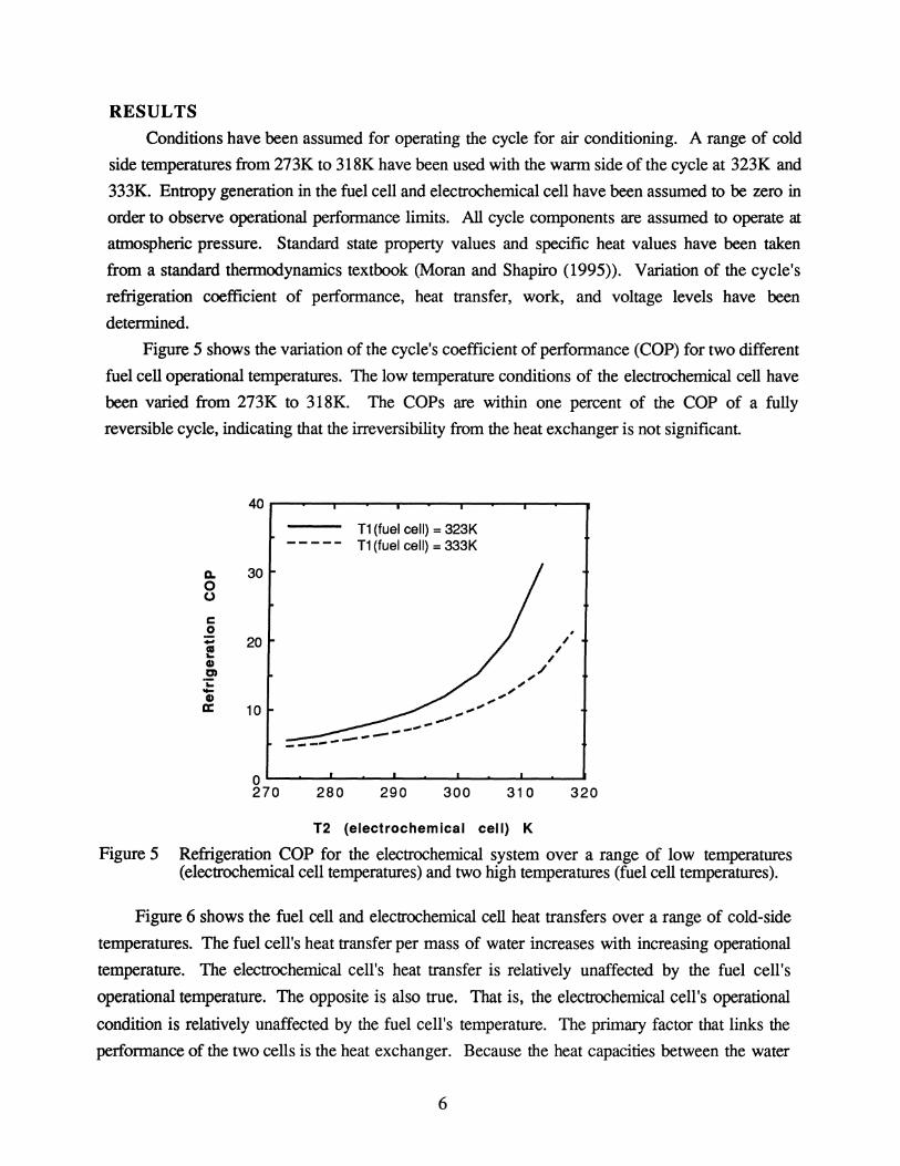
RESULTS Conditions have been assumed for operating the cycle for air conditioning. A range of cold
side temperatures from 273K to 318K have been used with the warm side of the cycle at 323K and
333K. Entropy generation in the fuel cell and electrochemical cell have been assumed to be zero in
order to observe operational performance limits. All cycle components are assumed to operate at
atmospheric pressure. Standard state property values and specific heat values have been taken
from a standard thermodynamics textbook (Moran and Shapiro (1995». Variation of the cycle's
refrigeration coefficient of performance, heat transfer, work, and voltage levels have been
determined.
Figure 5 shows the variation of the cycle's coefficient of performance (COP) for two different
fuel cell operational temperatures. The low temperature conditions of the electrochemical cell have
been varied from 273K to 318K. The COPs are within one percent of the COP of a fully
reversible cycle, indicating that the irreversibility from the heat exchanger is not significant.
a.. 30 o o r:::: o -as ... II C) ;: -II a:
20
10
T1 (fuel cell) = 323K T1 (fuel cell) = 333K
o~~--~----~----~----~------270 280 290 300 310 320
T2 (electrochemical cell) K
Figure 5 Refrigeration COP for the electrochemical system over a range of low temperatures (electrochemical cell temperatures) and two high temperatures (fuel cell temperatures).
Figure 6 shows the fuel cell and electrochemical cell heat transfers over a range of cold-side
temperatures. The fuel cell's heat transfer per mass of water increases with increasing operational
temperature. The electrochemical cell's heat transfer is relatively unaffected by the fuel cell's
operational temperature. The opposite is also true. That is, the electrochemical cell's operational
condition is relatively unaffected by the fuel cell's temperature. The primary factor that links the
performance of the two cells is the heat exchanger. Because the heat capacities between the water
6

and gas streams are not perfectly matched, variation of the fuel cell and electrochemical cell
operational temperatures affects the water temperature that enters the electrochemical cell. The
mismatch, however, results in a small irreversibility to the overall system. Figure 7 shows the
variation of the water outlet temperature from the heat exchanger relative to the operational
temperatures of the fuel cell and electrochemical cell.
3000 • • • • • • • • • •
.. " -" c !,::" t-" .. .. II II • 2500 " . ::I: m ~ -,,-' .. ~ ::s-
323K :::::: electrochemical cell '0 T1 =
" fuel cell .a
333K :::::: electrochemical cell c( T1 = fuel cell
2000 270 280 290 300 310 320
T2 (electrochemical cell) K
Figure 6 Electrochemical cell and fuel cell absolute heat transfer per water mass for two fuel cell temperatures over a range of electrochemical cell temperatures.
400 --a-- fuel cell = 323K
--r- heat exchanger water outlet
--0- fuel cell = 333K ...... ~ 350 ---+-- heat exchanger water outlet .....
" 0 0 0 0 0 0 0 0 0 0 .. ::s .. II .. " a. E 300
" t-
--+- electrochemical cell temperature
250~----~----~----~----~------
270 280 290 300 310 320
T2 (electrochemical cell) K
Figure 7 Plot of the water outlet temperature from the heat exchanger relative to the fuel cell and electrochemical cell temperatures.
7

Figure 8 shows the work required by the electrochemical cell and the work produced by the
fuel cell. The fuel cell's work output is reduced as its temperature is increased. The work
produced by the fuel cell is lower than the work required by the electrochemical cell. As the
electrochemical cell's temperature approaches the fuel cell's temperature, the work difference is
reduced to zero.
14000~~--~.----~----~--~~----~
13500
,¥ -
~ ...... o CD =:; CD i: 13000
- I :J CJ) • • • • • • • • • • - ,¥ 0 __
CII.., 323K --Is;- electrochemical cell J:I,¥ T1 c( __ =
12500 --.....- fuel cell
T1 333K=:= electrochemical cell
= fuel cell
12000 270 280 290 300 310 320
T2(electrochemical cell) K
Figure 8 Electrochemical cell and fuel cell work per water mass for two fuel cell temperatures over a range of electrochemical cell temperatures.
Figure 9 shows the voltages across the fuel cell and the electrochemical cell for the assumed
range of conditions. Voltages are determined by calculating the current flow per mole of water.
The current, relative to the work per mole in the fuel cell and electrochemical cell, determines the
voltage across each cell.
Irreversibilities in the fuel cell and electrochemical cell affect the system operation in different
manners. Irreversibilities, in general, lower the cycle's performance. In the fuel cell, a lower
voltage output occurs, thus requiring a larger voltage boost for driving the electrochemical cell.
Irreversibilities in the electrochemical cell affect the cycle in two ways. First, the voltage required
to operate the cell increases. The second, and more significant effect, is internal heat generation
that limits the amount of heat transferred into the electrochemical cell from its surroundings. When
the level of irreversibility increases sufficiently, a "neutral" voltage level is reached. This is the
limit where no external heat transfer occurs. Above the neutral voltage limit, the electrochemical
cell exhausts thermal energy to its surroundings. Ohta (1978) describes the types of
irreversibilities within hydrogen/oxygen electrolysis systems.
8

1.28
T1 323K=:= fuel cell = electrochemical cell
1.26 T1 333K:::=
fuel cell = electrochemical cell
• 1.24 C) II
= 0 1.22 > c c c c c c c c
1.20 0 0 0 0 0 0 0 0 0 0
1.18 270 280 290 300 310 320
T2 (electrochemical cell) K
Figure 9 Electrochemical cell and fuel cell voltages for two fuel cell temperatures over a range of electrochemical cell temperatures.
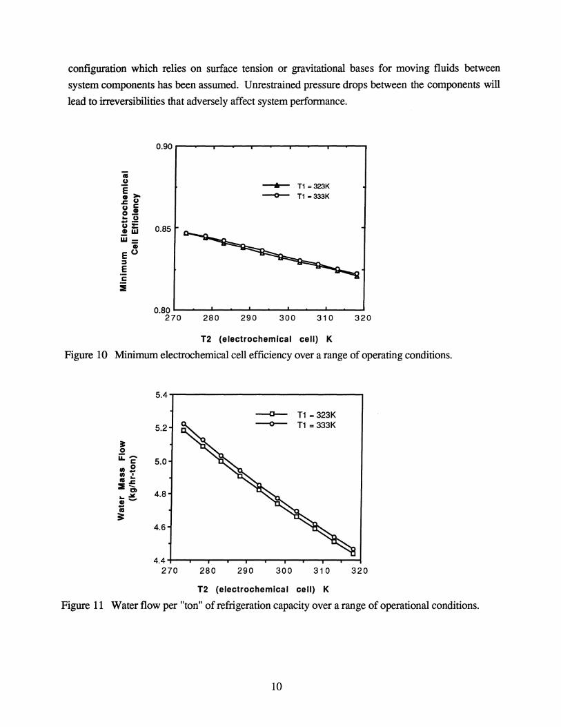
The operational limit of the cycle, when ireversibilities in the electrochemical cell reach the
neutral voltage level, can be determined by setting the electrochemical cell's heat transfer to zero.
The entropy generation term is included in the electrochemical cell's work relation, or alternatively,
the cell's reversible work can be divided by an efficiency parameter. Figure 10 shows the
electrochemical cell efficiency when irreversibilities cause the cell to operate at the neutral voltage
level. When cell efficiencies are below those shown in Figure 10, the system can no longer operate
in the refrigeration mode. The actual neutral voltage level is insensitive to the operational
conditions shown in Figure 10. The neutral voltage varies between 1.476 and 1.478 volts for the
conditions plotted. Brown, et.al. (1980) describe electrode surfaces with low overvoltage
characterisitics. Current densities less than 10 milliamps per square centimeter may be operated
with overvoltages that are 0.01 volts above the reversible limit.
The mass flow rate for achieving a desired level of refrigeration is shown in Figure 11.
Water flow rates for one "ton" (12,000 Btu/hr = 12,600 kJ/hr) of refrigeration is plotted over a
range of cell temperatures with reversible cell operation assumed. One ton of refrigeration is
typical of room air conditioners (window units). Mass flows are sensitive to the electrochemical
cell's temperature, however, the fuel cell's temperature is not as significant.
All results presented have assumed that the system operates uniformly at atmospheric
pressure. Variation of the system's pressure does not significantly affect the performance values
shown in the previous figures as long as a uniform pressure is assumed throughout the system. A
9
configuration which relies on surface tension or gravitational bases for moving fluids between
system components has been assumed. Unrestrained pressure drops between the components will
lead to irreversibilities that adversely affect system performance.
0.90
..
.!! --6- T1 =323K E>o ~ T1 =333K • u z: c u • 0-.. u ... -u= 0.85 .!!W w= • EO :::s E c 2
0.80 270 280 290 300 310 320
T2 (electrochemical cell) K
Figure 10 Minimum electrochemical cell efficiency over a range of operating conditions.
5.4
C T1 = 323K
5.2 0 T1 = 333K
• 0 u::- 5.0 c " 0 ,,~ II .. ::E:!!:
Q 4.8 .. ~ .-...
II
== 4.6
4.4 270 280 290 300 310 320
T2 (electrochemical cell) K
Figure 11 Water flow per "ton" of refrigeration capacity over a range of operational conditions.
10

CONCLUSIONS A method for operating a refrigeration cycle has been described. Practical development of the
system depends on several factors. High quality electrode surfaces must be used in order to keep
voltage drops and reaction resistances to a minimum. Electrolytes for the fuel cell and
electrochemical cell must be chosen. The costs associated with these components is another factor
affecting the economic feasibility of the proposed system.
A beneficial aspect of the proposed system is that it may be coupled to a variety of low
voltage, direct current electrical energy generators. Photovoltaic solar cells would be one example
of an energy source that may be directly compatible with the "current pumping" required by this
system. Cell modules would need to be "stacked" in a series configuration in order to have the
overall voltage differential match the voltage level available for driving the system. Stacking cell
modules is also desirable in order to keep current flow, and therefore electric circuit resistive losses
small.
Environmentally, the system is free of refrigerant compounds with ozone depletion and global
warming concerns. Safety issues regarding the movement of oxygen and hydrogen must be
address, however, the mass flow rates are quite small per ton of refrigeration effect and reasonable
designs should be able to minimize the actual system mass and volume in hydrogen and oxygen.
11

NOMENCLATURE
Co2 molar constant pressure specific heat of oxygen
CH2 molar constant pressure specific heat of hydrogen
CH20 molar constant pressure specific heat of water
h02 molar enthalpy of oxygen
hH2 molar enthalpy of hydrogen
hH20 molar enthalpy of water
n02 moles of oxygen transported
nH2 moles of hydrogen transported
nH20 moles of water transported
Oc electrochemical cell heat transfer
Qr fuel cell heat transfer
qc electrochemical cell heat transfer per mole of water
qr fuel cell heat transfer per mole of water
R universal gas constant
S02 molar entropy of oxygen
SH2 molar entropy of hydrogen
SH20 molar entropy of water
S gc entropy generation in the fuel cell
S gf entropy generation in the fuel cell
T 1 fuel cell operating temperature
T 2 electrochemical cell operating temperature
T2* water outlet temperature from the heat exchanger
We electrochemical cell work
W f fuel cell work
We electrochemical cell work per mole of water
Wf fuel cell work per mole of water
superscript
o indicates property (enthalpy or entropy) at standard state value (1 atmosphere and 298K)
subscripts
i indicates inlet stream to the system of interest
e indicates an exit stream from the component of interest
12

REFERENCES Appleby, A.I. and Foulkes, F.R., 1989, Fuel Cell Handbook, Van Nostrand Reinhold. Brown, D.E., Mahmoud, M.N., Turner, A.K., Hall, S.M., Fogarty, P.O., 1980, Low
overvoltage electrocatalysts for hydrogen evolving electrodes, Hydrogen Energy Progress, 3rd World Energy Conf., Tokyo, pp.151-164.
Casper, M.S., 1978, Hydrogen Manufacture by Electrolysis, Thermal Decomposition and Unusual Techniques, Noyes Data Corp.
Howell, I.R. and Buckius, R.O., 1992, Fundamental of Engineering Thermodynamics, 2nd Ed., McGraw-Hill, Inc., Ch. 11.
Moran, M.l and Shapiro, H.N., 1995, Fundamentals of Engineering Thermodynamics, 3rd Ed., Wiley, Ch.13.
Ohta, T., 1979, Solar-Hydrogen Energy Systems, Pergamon Press.
Soo, S.L., 1968, Direct Energy Conversion, Prentice-Hall, Chapter 3.
13