thermo-lag 3000 - pfp systems · 1 thermo-lag 3000 fire barrier system application manual nu-chem...
TRANSCRIPT
1
THERMO-LAG 3000 Fire Barrier System Application Manual
NU-CHEM Document Number
111397(E)
Revision: 2
2000-07-07
®
2
Notices and Statements
NOTICE
NU-CHEM, INC. PROPRIETARY RIGHTS ARE INCLUDED IN THE INFORMATION
DISCLOSED HEREIN. RECIPIENT AGREES THAT NEITHER THIS DOCUMENT NOR THE
INFORMATION DISCLOSED HEREIN NOR ANY PART THEREOF SHALL BE REPRODUCED OR
TRANSFERRED TO OTHER DOCUMENTS OR USED OR DISCLOSED TO OTHERS FOR
MANUFACTURING OR FOR ANY OTHER PURPOSE EXCEPT AS SPECIFICALLY AUTHORIZED
IN WRITING BY THE PRESIDENT OF NU-CHEM, INC.
THE INFORMATION AND TECHNICAL DATA CONTAINED IN THIS DOCUMENT IS ACCURATE AND COMPLETE TO THE BEST OF OUR KNOWLEDGE AS OF THE DATE PRINTED.
THE INFORMATION IN THIS DOCUMENT IS SUBJECT TO CHANGE WITHOUT NOTICE.
NU-CHEM, INC. MAKES NO WARRANTY OF ANY KIND WITH REGARD TO THIS PRINTED MATERIAL. NU-CHEM, INC. ASSUMES NO RESPONSIBILITY FOR ERRORS OR OMISSIONS
THAT MAY OCCUR IN THIS DOCUMENT. NU-CHEM, INC. DOES NOT MAKE A COMMITMENT TO KEEP THIS DOCUMENT CURRENT AND UP TO DATE.
NU-CHEM, INC., ITS EMPLOYEES AND AGENTS SHALL HAVE NO OBLIGATION OR LIABILITY FOR DAMAGES, INCLUDING BUT NOT LIMITED TO CONSEQUENTIAL DAMAGES
ARISING OUT OF OR IN CONNECTION WITH THE USE, OR INABILITY TO USE, THE INFORMATION INCLUDED IN THIS GUIDE.
Page ii
3
Revision History
NU-CHEM DOCUMENT NUMBER
Revision Number
Date Revised
Revision Details
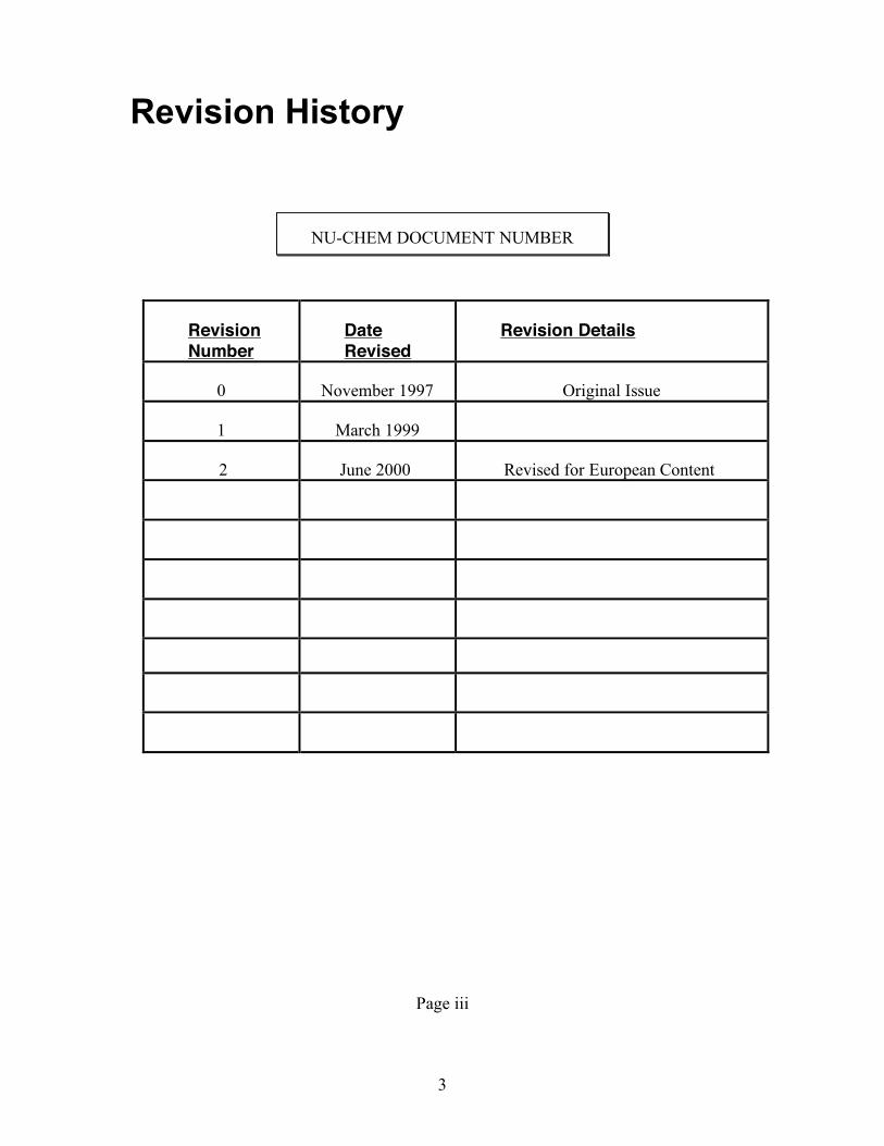
0 November 1997 Original Issue
1 March 1999
2 June 2000 Revised for European Content
Page iii

4
Table of Contents
Notices and Statements………………………………………………………………………………. ii Revision History……………………………………………………………………………………….. iii Table of Contents……………………………………………………………………………………… iv Preface…………………………………………………………………………………………………. vi Audience…………………………………………………………………………………………… vi Locating Information……………………………………………………………………………… vi Numbering System……………………………………………………………………………….. vi Breakdown of Information……………………………………………………………………….. vi Related Publication and Documents……………………………………………………………. vi Safety Precautions………………………………………………………………………………… vii Notes on Installation………………………………………………………………………………. vii Basis for Installation Procedures in This Guide……………………………………………….. vii Topcoats……………………………………………………………………………………………. vii Primers……………………………………………………………………………………………… vii 1.0 GENERAL CONDITIONS………………………………………………………….…… 8 1.1 SCOPE…………………………………………………………………………………… 8 1.2 QUALITY CONTROL MANUAL…………………………………………………….….. 8
1.2.1 QUALIFICATIONS OF APPLICATORS/RESPONSIBILITIES OF PERSONNEL…………………………………………………………………… 8
1.2.1.2 REQUIREMENTS……………………………………………………. 8 1.3 SAFETY PRECAUTIONS………………………………………………………………. 8 1.4 DELIVERY……………………………………………………………………………….. 9 1.5 STORAGE………………………………………………………………………………… 9 1.6 PROTECTION OF ADJACENT SURFACES…………………………………………. 9
2.0 MATERIALS……………………………………………………………………………… 10 2.1 PRIMERS………………………………………………………………………………… 10 2.2 THERMO-LAG 3000 SUBLIMING COATING………………………………………... 10 2.3 TOPCOATS………………………………………………………………………………. 10 2.4 FIBREGLASS REINFORCEMENT…………………………………………………….. 10
2.5 HIGH TEMPERATURE FABRIC REINFORCEMENT……………………………….. 10 2.6 METAL MESH REINFORCEMENT……………………………………………………. 11 2.6.1 PIN WELDING PROCEDURE……………………………………………… 11 2.6.2 MESH ATTACHMENT BY PINS……………………………………………… 11
3.0 EQUIPMENT (Minimum)………………………………………………………………… 12 3.1 PLURAL COMPONENT EQUIPMENT (For 100% and 95% Solids)………………. 12 3.1.1 EQUIPMENT START-UP PROCEDURE……………………………………. 13 3.2 SINGLE COMPONENT EQUIPMENT (For 95% Solids Only)……………………… 15 3.2.1 START-UP PROCEDURE…………………………………………………….. 15 4.0 PREPARATIONS PRIOR TO THERMO-LAG 3000 APPLICATION……………….. 16 4.1 DEGREASING, BLASTING AND PRIMING…………………………………………... 16 4.1.1 DEGREASING………………………………………………………………….. 16 4.1.2 BLASTING………………………………………………………………………. 16 4.1.3 PRIMING………………………………………………………………………… 16 4.1.3.1 PRIMER THICKNESS/ADHESION MEASUREMENTS………….. 17 4.1.3.2 PRIMER REACTIVATING…………………………………………… 17 4.1.4 PRIMER ADHESION…………………………………………………………… 17 4.2 SURFACE PREPARATION WHERE GRIT BLAST NOT ALLOWED……………… 17 4.3 GALVANIZED SURFACE PREPARATION…………………………………………… 17
4.4 METALLISATION………………………………………………………………………… 18 4.5 WELD CUT BACK……………………………………………………………………….. 19
5.0 THERMO-LAG 3000 APPLICATION PROCEDURES……………………………….. 20

5
5.1 INSTALLATION OF FIBREGLASS REINFORCEMENT ON STRUCTURAL STEEL I AND H SECTIONS……………………………………………………………. 21
5.2 FINAL THERMO-LAG 300 APPLICATION……………………………………………. 22 5.2.1 JOINT TERMINATION…………………………………………………………. 22
5.3 FINAL THICKNESS……………………………………………………………………… 22 5.4 SAMPLE INSTALLATION………………………………………………………………. 22 5.5 EQUIPMENT CLEANUP/FLUSHING………………………………………………….. 22 5.6 TOPCOATING……………………………………………………………………………. 23 5.7 RECORD KEEPING…………………………………………………………………….. 23
6.0 CLEAN-UP……………………………………………………………………………….. 29 7.0 REMOVAL AND REPAIR PROCEDURES…………………………………………… 29 7.1 REMOVAL……………………………………………………………………………….. 29 7.2 REPAIRS – GENERAL…………………………………………………………………. 29
6
Preface Audience
We assume that applicators of NU-CHEM, Inc. products understand the terminology associated with our products and the various pieces of spray equipment and application techniques.
The installation of the THERMO-LAG 3000 Fire Barrier System shall be performed only by contractor personnel who have been trained or qualified by NU-CHEM, Inc.
in the installation of the materials. Locating Information
This guide incorporates a number of aids to help locate information easily.
• Table of Contents • Figure and Table Listings • Page Headers and Footers • Frequent Section, Subsection, and Topic Headings
Numbering System
To avoid a cumbersome numbering system, only chapters, sections, and subsections have a numerical designation. For example “2.3.4” represents Chapter 2, Section 3, Subsection 4.
Illustrations and drawings generally appear at the end of this document. Breakdown of Information
Frequent section and subject headings highlight other significant information within a chapter. Heading type style and indentations indicate the level of importance for the topics.
Related Publications and Documents
This document occasionally refers to other Guides, data sheets, or specifications that may be helpful. Copies are available from NU-CHEM, Inc.
7
Other documents that may be helpful include: • OSHA - Occupational Safety and Health Administration safety rules • National Spray Equipment Manufacturers Association precautions for spraying. • Power tools, hand tools or other mechanical equipment operating procedures
Safety Precautions
THERMO-LAG 3000 Bulk Grade Material weighs approximately 1.1 - 1.2 kilos per litre. Caution should be taken when lifting and moving the material to prevent injury.
Observe the National Spray Equipment Manufacturers Association precautions for spraying.
DO NOT point spray gun at any part of the human body.
Notes On Installation
Basis for Installation Procedures in This Guide
The installation steps and procedures in this guide were prepared with the best available data. All of the steps and procedures presented in this guide are based upon tests. As additional test and installation data becomes available, including revised installation procedures, NU-CHEM, Inc. may update and modify this guide.
NOTE:
This is a general Application Manual and cannot cover all possible situations, which may arise in the field. For technical assistance, contact NU-CHEM, Inc..
USA HEADQUARTERS
2200 CASSENS DRIVE ST. LOUIS, MISSOURI
63026 TEL: (636) 349 1233 FAX: (636) 349 1207
E-MAIL: [email protected] www.Nu-ChemUSA.com
EUROPE & S.E. ASIA
UPPER FLOOR, 53 NEWLAND STREET
WITHAM ESSEX
UK CM8 2BD TEL: (44) 1376 501061 FAX: (44) 1376 520110
E-MAIL: [email protected]
8
1.0 GENERAL CONDITIONS
1.1 SCOPE
This Application Manual describes the requirements for the application of the THERMO-LAG 3000 Fire Barrier System to steel surfaces. For the application of THERMO-LAG 3000 to any other substrates, contact NU-CHEM Inc.
1.2 QUALITY CONTROL MANUAL
1.2.1 QUALIFICATIONS OF APPLICATORS/ RESPONSIBILITIES OF PERSONNEL
A Qualified Applicator having required levels of training, equipment, and experience shall perform the application. It shall be the responsibility of the Application contractor to document compliance with both Project and Nu-Chem requirements.
1.2.1.2 REQUIREMENTS
In order to qualify, an Applicator shall:
a) Be experienced in the application of thick film coatings, preferably epoxy based.
(b) Undergo specific training by NU-CHEM.
(c) Have the necessary approved spray application equipment and quality control instrumentation recommended.
(d) Have in place an acceptable QA/QC system and be prepared to permit NU-CHEM audits.
(e) Understand and recognise their statutory obligations with regard to health and safety.
1.3 SAFETY PRECAUTIONS
The Applicator shall follow standard industrial hygiene practices for the handling of chemical coatings and shall conform to applicable codes of practice, regulations, and Owner safety rules in all respects. Reference THERMO-LAG 3000 MSDS and Health and Safety Data Sheets for additional information and instruction. National requirements for procedures and documentation shall also be observed.
Where power tools hand tools, spray equipment or other mechanical equipment are being used, the proper operating procedures for each tool or piece of equipment, as well as eye, hearing and respiratory protection should be followed. Equipment used to apply THERMO-LAG 3000 is under high pressure. Any injury caused by high-pressure liquids can be serious and immediate medical attention should be sought.
9
1.4 DELIVERY
THERMO-LAG 3000 shall be delivered to the site in original, unopened containers, bearing clearly visible product names, batch number, name of manufacturer, expiration date, and storage instructions.
1.5 STORAGE
THERMO-LAG 3000 not in immediate use shall be stored off the ground in a covered area assigned for that purpose by the Owner. The materials in storage shall be protected from temperatures above 32°C (90°F). Freezing is not a specific problem with THERMO-LAG 3000. Repeated freeze - thaw cycles should be avoided. Prior to use, THERMO-LAG 3000 should be heated to a minimum of 24°C(75°F) and maintained at this temperature for at least 24 hours.
1.6 PROTECTION OF ADJACENT SURFACES
The applicator shall mask off all adjacent areas and equipment from material overspray during the application. Overspray shall be removed promptly before material has cured. When applying these coating in windy conditions, additional precautions to control overspray should be undertaken.
10
2.0 MATERIALS
The THERMO-LAG 3000 Fire Barrier System consists of the following materials:
2.1 PRIMERS
All primer systems must be accepted by NU-CHEM prior to use under THERMO-LAG 3000. The acceptable primer system shall be applied to properly prepared surfaces in accordance with the manufacturer's and project specifications and shall not exceed a dry film thickness of 110 microns.
Final dry film thickness in excess of this value shall be agreed upon by NU-CHEM, Inc. in writing.
2.2 THERMO-LAG 3000 SUBLIMING COATING
THERMO-LAG 3000 is a two component, thermally activated, subliming, epoxy coating. When exposed to flame, the material volatilises at fixed temperatures, exhibits a volume increase through formation of a multicellular matrix and absorbs and blocks heat to protect the substrate material.
2.3 TOPCOATS
Topcoat systems must be acceptable to NU-CHEM prior to use over THERMO-LAG 3000. All topcoats shall be applied in accordance with the manufacturers and project specifications.
2.4 FIBREGLASS REINFORCEMENT
The fibreglass reinforcement shall be 5.3 oz./yd2 (180 grams/m2), Type "E", and shall be obtained from NU-CHEM Inc. The application details of the fibreglass reinforcement are dependent upon the design, size of steel, project requirements, etc.
2.5 HIGH TEMPERATURE FABRIC REINFORCEMENT
The high temperature fabric reinforcement shall an open weave and be obtained from NU-CHEM Inc. The application details of the high temperature fabric reinforcement are dependent upon the design, size of steel, project requirements, etc.

11
2.6 METAL MESH REINFORCEMENT Metal mesh shall without exception be mechanically fixed to the surface of the steel to be coated. Mechanical fixing shall be either by the configuration of pre-formed mesh sections, lacing/tying with wire of at least an equal gauge, or by welded pins.
2.6.1 PIN WELDING PROCEDURE Pins shall be attached to the substrate by capacitance discharge. Spacing between pins shall not exceed 300mm and shall form a diamond or irregular pattern rather than straight lines.
Pins shall be 2/3mm diameter copper coated mild steel. Exceptions may be permitted, contact Nu-Chem for advice. Length shall be 25 – 50 mm dependent on the final thickness of Thermo-lag 3000.
Preferably pins shall be attached prior to blasting and priming. For pins that have been attached after priming, the weld-affected area shall be thoroughly cleaned and the primer reinstated prior to Thermo-lag application. The only exception would be if application of Thermo-lag takes place within 3 hours of the re-preparation of the surface around the newly attached pin. In such circumstances it is permissible to apply Thermo-lag without reinstating the primer.
After the pin pattern has been marked out, the surface must be ground to bare metal before the pin is attached. At the start of production the first 20 pins shall be tested. Test procedure is that each of the 20 pins shall be bent to 45o then returned to the vertical. A suitable tool shall be used and care taken to ensure that the bend occurs at the root of the weld. All 20 pins must remain attached, if a single failure occurs the welding machine shall be recalibrated and the test repeated until 100% pass is recorded. Such a test shall be performed at the start of each production shift and the results documented.
2.6.2 MESH ATTACHMENT BY PINS. Wire mesh shall be retained in conjunction with pins by installing the mesh and retaining it by knocking over the pins, trapping the mesh against the surface of the steel or the surface of an installed coating of Thermo-lag 3000 (depending upon the rating).
12
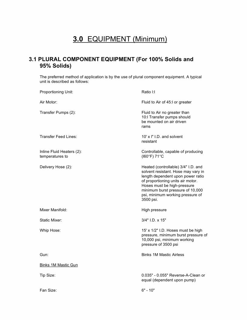
3.0 EQUIPMENT (Minimum)
3.1 PLURAL COMPONENT EQUIPMENT (For 100% Solids and 95% Solids)
The preferred method of application is by the use of plural component equipment. A typical unit is described as follows:
Proportioning Unit: Ratio l:l
Air Motor: Fluid to Air of 45:l or greater
Transfer Pumps (2): Fluid to Air no greater than 10:l Transfer pumps should be mounted on air driven rams
Transfer Feed Lines: 10' x l" I.D. and solvent resistant
Inline Fluid Heaters (2): Controllable, capable of producing temperatures to (l60°F) 71°C
Delivery Hose (2): Heated (controllable) 3/4" I.D. and solvent resistant. Hose may vary in length dependent upon power ratio of proportioning units air motor. Hoses must be high-pressure minimum burst pressure of 10,000 psi, minimum working pressure of 3500 psi.
Mixer Manifold: High pressure
Static Mixer: 3/4" I.D. x 15"
Whip Hose: 15' x 1/2" I.D. Hoses must be high pressure, minimum burst pressure of 10,000 psi, minimum working pressure of 3500 psi
Gun: Binks 1M Mastic Airless
Binks 1M Mastic Gun
Tip Size: 0.035" - 0.055" Reverse-A-Clean or equal (dependent upon pump)
Fan Size: 6" - 10"
13
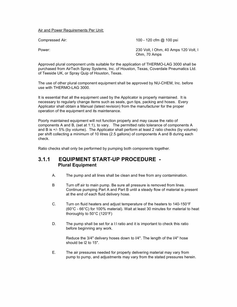
Air and Power Requirements Per Unit:
Compressed Air: 100 - 120 cfm @ 100 psi
Power: 230 Volt, l Ohm, 40 Amps 120 Volt, l Ohm, 70 Amps
Approved plural component units suitable for the application of THERMO-LAG 3000 shall be purchased from AirTech Spray Systems, Inc. of Houston, Texas, Coverdale Pneumatics Ltd. of Teeside UK, or Spray Quip of Houston, Texas.
The use of other plural component equipment shall be approved by NU-CHEM, Inc. before use with THERMO-LAG 3000.
It is essential that all the equipment used by the Applicator is properly maintained. It is necessary to regularly change items such as seals, gun tips, packing and hoses. Every Applicator shall obtain a Manual (latest revision) from the manufacturer for the proper operation of the equipment and its maintenance.
Poorly maintained equipment will not function properly and may cause the ratio of components A and B, (set at 1:1), to vary. The permitted ratio tolerance of components A and B is +/- 5% (by volume). The Applicator shall perform at least 2 ratio checks (by volume) per shift collecting a minimum of 10 litres (2.5 gallons) of components A and B during each check.
Ratio checks shall only be performed by pumping both components together.
3.1.1 EQUIPMENT START-UP PROCEDURE - Plural Equipment
A. The pump and all lines shall be clean and free from any contamination.
B Turn off air to main pump. Be sure all pressure is removed from lines. Continue pumping Part A and Part B until a steady flow of material is present at the end of each fluid delivery hose.
C. Turn on fluid heaters and adjust temperature of the heaters to 140-150°F (60°C - 66°C) for 100% material). Wait at least 30 minutes for material to heat thoroughly to 50°C (120°F)
D. The pump shall be set for a l:l ratio and it is important to check this ratio before beginning any work.
Reduce the 3/4" delivery hoses down to l/4". The length of the l/4" hose should be l2 to 15".
E. The air pressures needed for properly delivering material may vary from pump to pump, and adjustments may vary from the stated pressures herein.
14
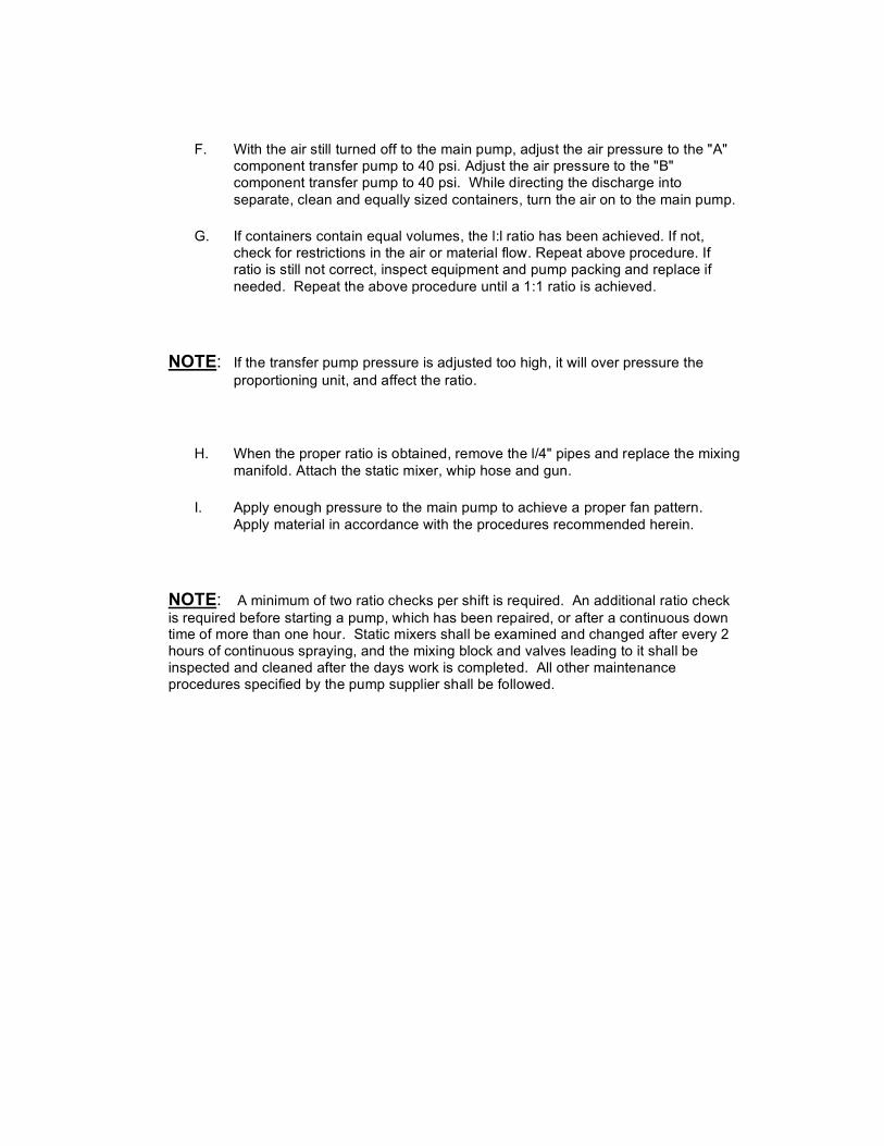
F. With the air still turned off to the main pump, adjust the air pressure to the "A" component transfer pump to 40 psi. Adjust the air pressure to the "B" component transfer pump to 40 psi. While directing the discharge into separate, clean and equally sized containers, turn the air on to the main pump.
G. If containers contain equal volumes, the l:l ratio has been achieved. If not, check for restrictions in the air or material flow. Repeat above procedure. If ratio is still not correct, inspect equipment and pump packing and replace if needed. Repeat the above procedure until a 1:1 ratio is achieved.
NOTE: If the transfer pump pressure is adjusted too high, it will over pressure the proportioning unit, and affect the ratio.
H. When the proper ratio is obtained, remove the l/4" pipes and replace the mixing manifold. Attach the static mixer, whip hose and gun.
I. Apply enough pressure to the main pump to achieve a proper fan pattern. Apply material in accordance with the procedures recommended herein.
NOTE: A minimum of two ratio checks per shift is required. An additional ratio check is required before starting a pump, which has been repaired, or after a continuous down time of more than one hour. Static mixers shall be examined and changed after every 2 hours of continuous spraying, and the mixing block and valves leading to it shall be inspected and cleaned after the days work is completed. All other maintenance procedures specified by the pump supplier shall be followed.
15
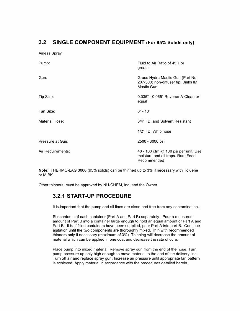
3.2 SINGLE COMPONENT EQUIPMENT (For 95% Solids only)
Airless Spray
Pump: Fluid to Air Ratio of 45:1 or greater
Gun: Graco Hydra Mastic Gun (Part No. 207-300) non-diffuser tip, Binks lM Mastic Gun
Tip Size: 0.035" - 0.065" Reverse-A-Clean or equal
Fan Size: 6" - 10"
Material Hose: 3/4" I.D. and Solvent Resistant
1/2" I.D. Whip hose
Pressure at Gun: 2500 - 3000 psi
Air Requirements: 40 - 100 cfm @ 100 psi per unit. Use moisture and oil traps. Ram Feed Recommended
Note: THERMO-LAG 3000 (95% solids) can be thinned up to 3% if necessary with Toluene or MIBK.
Other thinners must be approved by NU-CHEM, Inc. and the Owner.
3.2.1 START-UP PROCEDURE
It is important that the pump and all lines are clean and free from any contamination.
Stir contents of each container (Part A and Part B) separately. Pour a measured amount of Part B into a container large enough to hold an equal amount of Part A and Part B. If half filled containers have been supplied, pour Part A into part B. Continue agitation until the two components are thoroughly mixed. Thin with recommended thinners only if necessary (maximum of 3%). Thinning will decrease the amount of material which can be applied in one coat and decrease the rate of cure.
Place pump into mixed material. Remove spray gun from the end of the hose. Turn pump pressure up only high enough to move material to the end of the delivery line. Turn off air and replace spray gun. Increase air pressure until appropriate fan pattern is achieved. Apply material in accordance with the procedures detailed herein.
16
4.0 PREPARATIONS PRIOR TO THERMO-LAG 3000 APPLICATION
4. DEGREASING, BLASTING AND PRIMING
4.1.1 DEGREASING
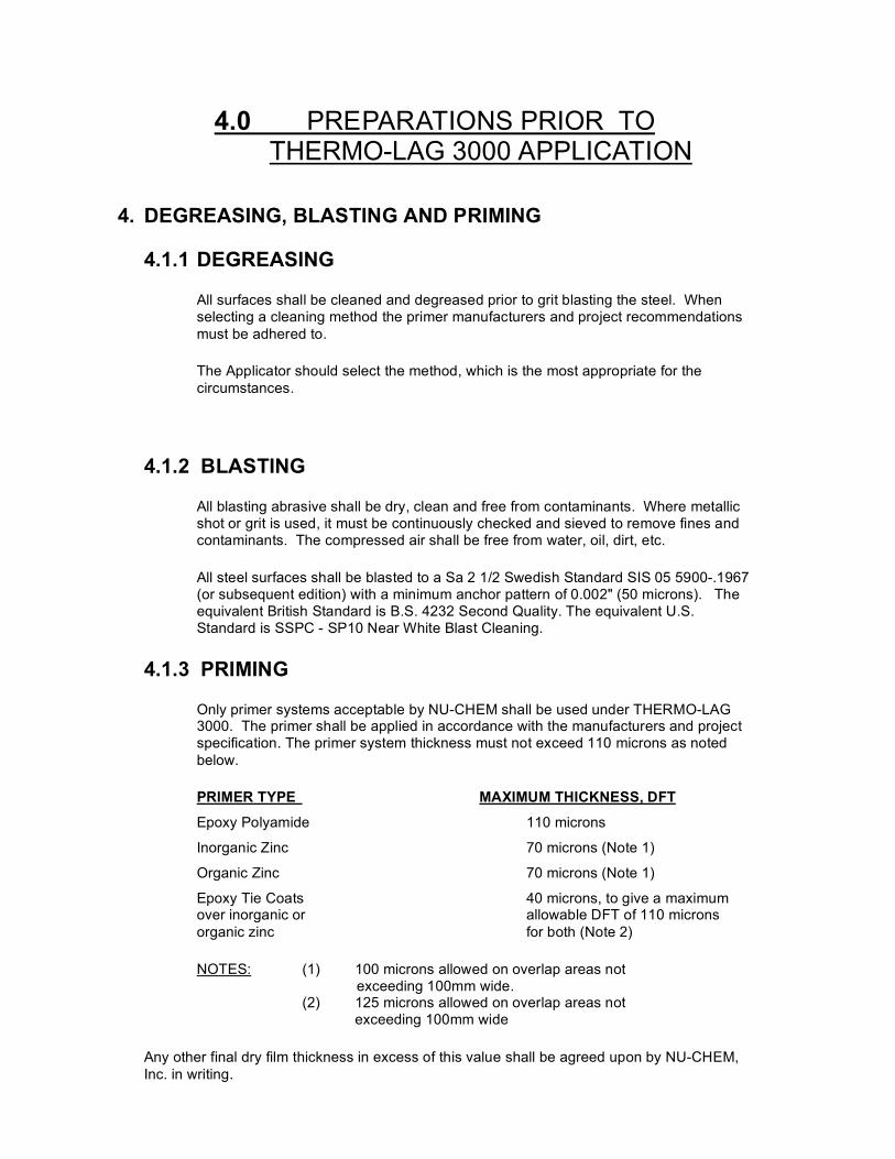
All surfaces shall be cleaned and degreased prior to grit blasting the steel. When selecting a cleaning method the primer manufacturers and project recommendations must be adhered to.
The Applicator should select the method, which is the most appropriate for the circumstances.
4.1.2 BLASTING
All blasting abrasive shall be dry, clean and free from contaminants. Where metallic shot or grit is used, it must be continuously checked and sieved to remove fines and contaminants. The compressed air shall be free from water, oil, dirt, etc.
All steel surfaces shall be blasted to a Sa 2 1/2 Swedish Standard SIS 05 5900-.1967 (or subsequent edition) with a minimum anchor pattern of 0.002" (50 microns). The equivalent British Standard is B.S. 4232 Second Quality. The equivalent U.S. Standard is SSPC - SP10 Near White Blast Cleaning.
4.1.3 PRIMING
Only primer systems acceptable by NU-CHEM shall be used under THERMO-LAG 3000. The primer shall be applied in accordance with the manufacturers and project specification. The primer system thickness must not exceed 110 microns as noted below.
PRIMER TYPE MAXIMUM THICKNESS, DFT
Epoxy Polyamide 110 microns
Inorganic Zinc 70 microns (Note 1)
Organic Zinc 70 microns (Note 1)
Epoxy Tie Coats 40 microns, to give a maximum over inorganic or allowable DFT of 110 microns organic zinc for both (Note 2)
NOTES: (1) 100 microns allowed on overlap areas not exceeding 100mm wide. (2) 125 microns allowed on overlap areas not exceeding 100mm wide
Any other final dry film thickness in excess of this value shall be agreed upon by NU-CHEM, Inc. in writing.
17
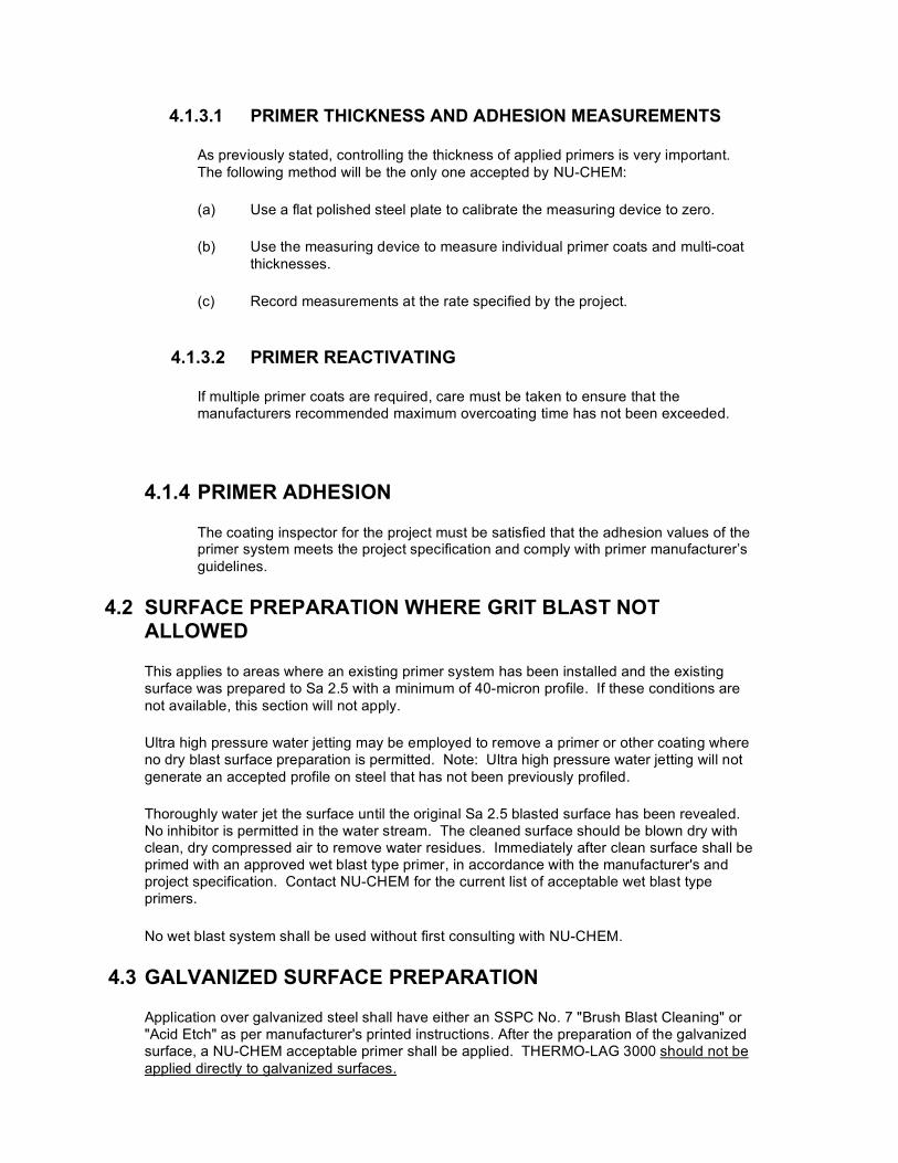
4.1.3.1 PRIMER THICKNESS AND ADHESION MEASUREMENTS
As previously stated, controlling the thickness of applied primers is very important. The following method will be the only one accepted by NU-CHEM:
(a) Use a flat polished steel plate to calibrate the measuring device to zero.
(b) Use the measuring device to measure individual primer coats and multi-coat thicknesses.
(c) Record measurements at the rate specified by the project.
4.1.3.2 PRIMER REACTIVATING
If multiple primer coats are required, care must be taken to ensure that the manufacturers recommended maximum overcoating time has not been exceeded.
4.1.4 PRIMER ADHESION
The coating inspector for the project must be satisfied that the adhesion values of the primer system meets the project specification and comply with primer manufacturer’s guidelines.
4.2 SURFACE PREPARATION WHERE GRIT BLAST NOT ALLOWED
This applies to areas where an existing primer system has been installed and the existing surface was prepared to Sa 2.5 with a minimum of 40-micron profile. If these conditions are not available, this section will not apply.
Ultra high pressure water jetting may be employed to remove a primer or other coating where no dry blast surface preparation is permitted. Note: Ultra high pressure water jetting will not generate an accepted profile on steel that has not been previously profiled.
Thoroughly water jet the surface until the original Sa 2.5 blasted surface has been revealed. No inhibitor is permitted in the water stream. The cleaned surface should be blown dry with clean, dry compressed air to remove water residues. Immediately after clean surface shall be primed with an approved wet blast type primer, in accordance with the manufacturer's and project specification. Contact NU-CHEM for the current list of acceptable wet blast type primers.
No wet blast system shall be used without first consulting with NU-CHEM.
4.3 GALVANIZED SURFACE PREPARATION
Application over galvanized steel shall have either an SSPC No. 7 "Brush Blast Cleaning" or "Acid Etch" as per manufacturer's printed instructions. After the preparation of the galvanized surface, a NU-CHEM acceptable primer shall be applied. THERMO-LAG 3000 should not be applied directly to galvanized surfaces.
18
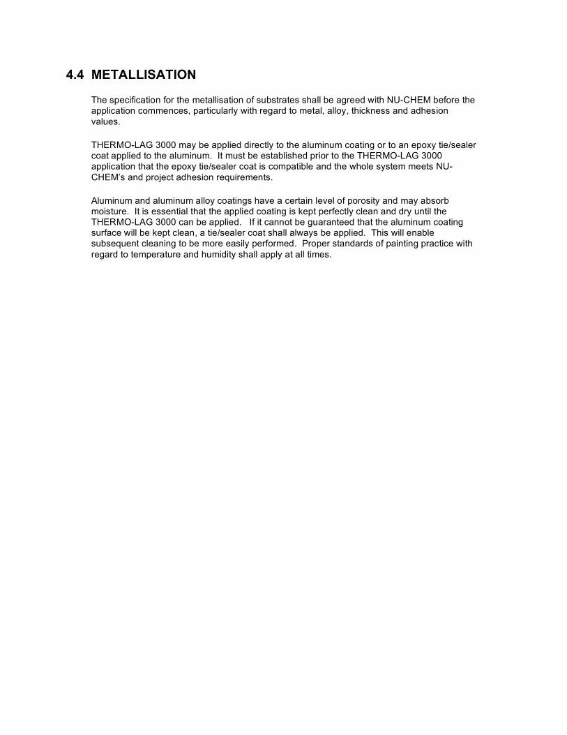
4.4 METALLISATION
The specification for the metallisation of substrates shall be agreed with NU-CHEM before the application commences, particularly with regard to metal, alloy, thickness and adhesion values.
THERMO-LAG 3000 may be applied directly to the aluminum coating or to an epoxy tie/sealer coat applied to the aluminum. It must be established prior to the THERMO-LAG 3000 application that the epoxy tie/sealer coat is compatible and the whole system meets NU-CHEM’s and project adhesion requirements.
Aluminum and aluminum alloy coatings have a certain level of porosity and may absorb moisture. It is essential that the applied coating is kept perfectly clean and dry until the THERMO-LAG 3000 can be applied. If it cannot be guaranteed that the aluminum coating surface will be kept clean, a tie/sealer coat shall always be applied. This will enable subsequent cleaning to be more easily performed. Proper standards of painting practice with regard to temperature and humidity shall apply at all times.
19
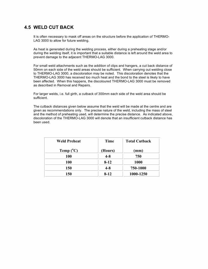
4.5 WELD CUT BACK
It is often necessary to mask off areas on the structure before the application of THERMO-LAG 3000 to allow for future welding.
As heat is generated during the welding process, either during a preheating stage and/or during the welding itself, it is important that a suitable distance is left around the weld area to prevent damage to the adjacent THERMO-LAG 3000.
For small weld attachments such as the addition of clips and hangers, a cut back distance of 50mm on each side of the weld areas should be sufficient. When carrying out welding close to THERMO-LAG 3000, a discoloration may be noted. This discoloration denotes that the THERMO-LAG 3000 has received too much heat and the bond to the steel is likely to have been affected. When this happens, the discoloured THERMO-LAG 3000 must be removed as described in Removal and Repairs.
For larger welds, i.e. full girth, a cutback of 300mm each side of the weld area should be sufficient.
The cutback distances given below assume that the weld will be made at the centre and are given as recommendations only. The precise nature of the weld, including the mass of steel and the method of preheating used, will determine the precise distance. As indicated above, discoloration of the THERMO-LAG 3000 will denote that an insufficient cutback distance has been used.
Weld Preheat
Temp (oC)
Time
(Hours)
Total Cutback
(mm) 100 4-8 750 100 8-12 1000 150 4-8 750-1000 150 8-12 1000-1250
20
5.0 THERMO-LAG 3000 APPLICATION PROCEDURES
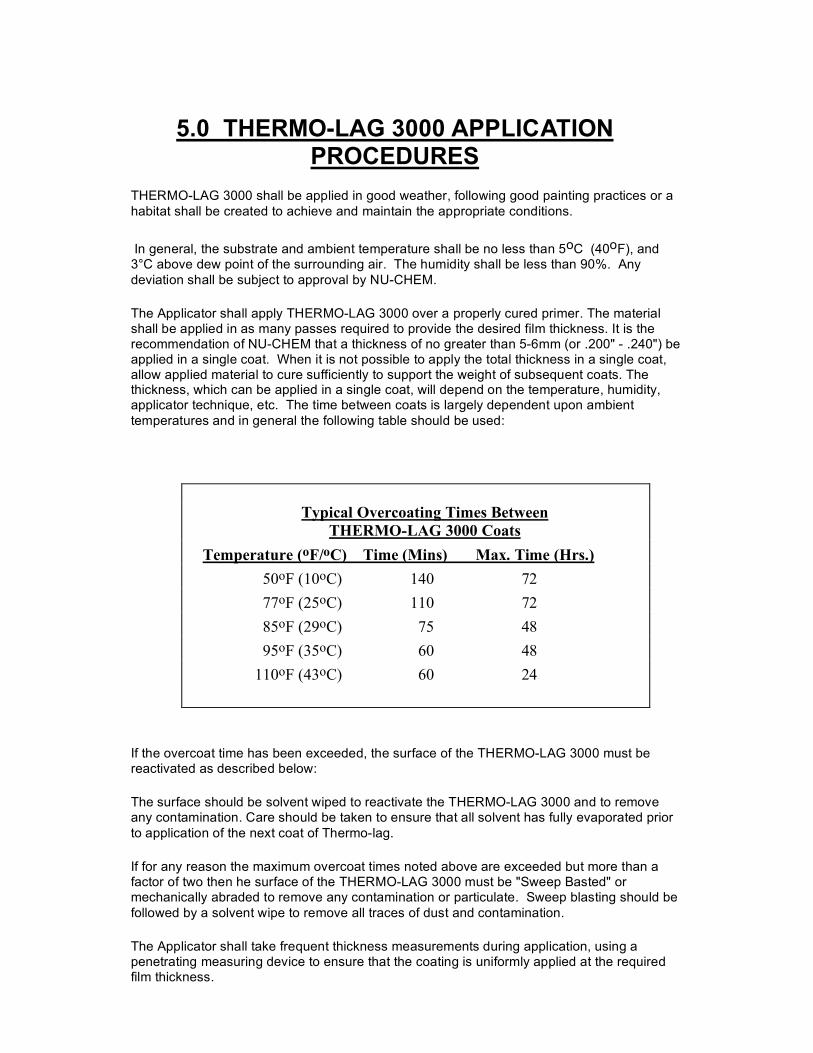
THERMO-LAG 3000 shall be applied in good weather, following good painting practices or a habitat shall be created to achieve and maintain the appropriate conditions.
In general, the substrate and ambient temperature shall be no less than 5oC (40oF), and 3°C above dew point of the surrounding air. The humidity shall be less than 90%. Any deviation shall be subject to approval by NU-CHEM.
The Applicator shall apply THERMO-LAG 3000 over a properly cured primer. The material shall be applied in as many passes required to provide the desired film thickness. It is the recommendation of NU-CHEM that a thickness of no greater than 5-6mm (or .200" - .240") be applied in a single coat. When it is not possible to apply the total thickness in a single coat, allow applied material to cure sufficiently to support the weight of subsequent coats. The thickness, which can be applied in a single coat, will depend on the temperature, humidity, applicator technique, etc. The time between coats is largely dependent upon ambient temperatures and in general the following table should be used:
Typical Overcoating Times Between
THERMO-LAG 3000 Coats Temperature (oF/oC) Time (Mins) Max. Time (Hrs.) 50oF (10oC) 140 72 77oF (25oC) 110 72 85oF (29oC) 75 48 95oF (35oC) 60 48 110oF (43oC) 60 24
If the overcoat time has been exceeded, the surface of the THERMO-LAG 3000 must be reactivated as described below:
The surface should be solvent wiped to reactivate the THERMO-LAG 3000 and to remove any contamination. Care should be taken to ensure that all solvent has fully evaporated prior to application of the next coat of Thermo-lag.
If for any reason the maximum overcoat times noted above are exceeded but more than a factor of two then he surface of the THERMO-LAG 3000 must be "Sweep Basted" or mechanically abraded to remove any contamination or particulate. Sweep blasting should be followed by a solvent wipe to remove all traces of dust and contamination.
The Applicator shall take frequent thickness measurements during application, using a penetrating measuring device to ensure that the coating is uniformly applied at the required film thickness.
21
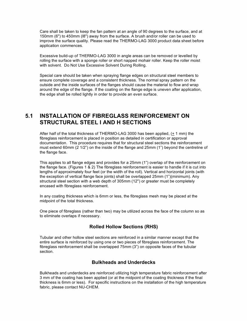
Care shall be taken to keep the fan pattern at an angle of 90 degrees to the surface, and at 150mm (6") to 450mm (l8") away from the surface. A brush and/or roller can be used to improve the surface quality. Please read the THERMO-LAG 3000 product data sheet before application commences.
Excessive build-up of THERMO-LAG 3000 in angle areas can be removed or levelled by rolling the surface with a sponge roller or short napped mohair roller. Keep the roller moist with solvent. Do Not Use Excessive Solvent During Rolling.
Special care should be taken when spraying flange edges on structural steel members to ensure complete coverage and a consistent thickness. The normal spray pattern on the outside and the inside surfaces of the flanges should cause the material to flow and wrap around the edge of the flange. If the coating on the flange edge is uneven after application, the edge shall be rolled lightly in order to provide an even surface.
5.1 INSTALLATION OF FIBREGLASS REINFORCEMENT ON STRUCTURAL STEEL I AND H SECTIONS
After half of the total thickness of THERMO-LAG 3000 has been applied, (+ 1 mm) the fibreglass reinforcement is placed in position as detailed in certification or approval documentation. This procedure requires that for structural steel sections the reinforcement must extend 60mm (2 1/2”) on the inside of the flange and 25mm (1”) beyond the centreline of the flange face.
This applies to all flange edges and provides for a 25mm (1”) overlap of the reinforcement on the flange face. (Figures 1 & 2) The fibreglass reinforcement is easier to handle if it is cut into lengths of approximately four feet (or the width of the roll). Vertical and horizontal joints (with the exception of vertical flange face joints) shall be overlapped 25mm (1”)(minimum). Any structural steel section with a web depth of 305mm (12") or greater must be completely encased with fibreglass reinforcement.
In any coating thickness which is 6mm or less, the fibreglass mesh may be placed at the midpoint of the total thickness.
One piece of fibreglass (rather than two) may be utilized across the face of the column so as to eliminate overlaps if necessary.
Rolled Hollow Sections (RHS)
Tubular and other hollow steel sections are reinforced in a similar manner except that the entire surface is reinforced by using one or two pieces of fibreglass reinforcement. The fibreglass reinforcement shall be overlapped 75mm (3”) on opposite faces of the tubular section.
Bulkheads and Underdecks
Bulkheads and underdecks are reinforced utilizing high temperature fabric reinforcement after 3 mm of the coating has been applied (or at the midpoint of the coating thickness if the final thickness is 6mm or less). For specific instructions on the installation of the high temperature fabric, please contact NU-CHEM.

22
Application of THERMO-LAG 3000 should continue immediately following the installation of the reinforcement. Care must be taken to insure that the reinforcement is firmly encapsulated in the THERMO-LAG 3000. If necessary, a solvent moist roller may be used to embed the fibreglass reinforcement. Care should though be taken not to use too much solvent and that the solvent has fully evaporated prior to application of the next coat.
All contamination must be removed from the surface of the THERMO-LAG 3000 before applying the next coat.
5.2 FINAL THERMO-LAG 3000 APPLICATION
After the reinforcement has been installed, apply THERMO-LAG 3000 to the final required thickness in as many coats as is necessary to achieve that thickness. Any overcoating shall be done within 72 hours of the prior coat, or as stated in section 5.0 of this Manual. If the time is exceeded, the surface must be sweep blasted or mechanically abraded and cleaned with an approved solvent to insure proper bonding between the two coats. Imbedded reinforcement shall be covered with at least 1mm of THERMO-LAG 3000 prior to daily shutdown.
5.2.1 JOINT TERMINATION
Where the THERMO-LAG 3000 terminates to non-fire protected steel, the THERMO- LAG 3000 shall be sprayed to the specified thickness for the given length and bevelled on a 45° angle down to the substrate.
5.3 FINAL THICKNESS
The final thickness will be specified in project drawings and Owner specifications. The thickness is normally based on average thickness, however, in some projects, a minimum thickness may be specified. When an average thickness is specified, the minimum acceptable thickness for any one point shall not be less than 85% of the listed thickness, or 1.5mm (.060”), whichever yields the lesser thickness. The final decision on thickness criteria is at the sole discretion of the Owner.
After THERMO-LAG 3000 has cured, an approved thickness gauge shall be used to ensure the thickness requirements have been met. Thicknesses below specification shall be built up to specified thickness by the application of additional THERMO-LAG 3000. An alternate method of thickness measurement is drilling a pilot hole and using a penetrating measuring device. It is required to fill all probe holes with THERMO-LAG 3000 after measurements have been taken.
5.4 SAMPLE INSTALLATION
Prior to actual production work, a sample test area shall be prepared following all specified procedures. This sample will then be approved by representatives of the Owner, Applicator, Architect and any others having a vested interest in the installation. All work following the sample installation shall conform to the standards of the site sample.
5.5 EQUIPMENT CLEANUP / FLUSHING
Clean up at the end of the spray period can be achieved using hot water (150°F) (66°C) or an appropriate solvent. (consult NU-CHEM, Inc.) The cleaning solvents, must be approved by the Owner. Be advised that the spray gun, static mixer and block assembly, should be hand cleaned.
23
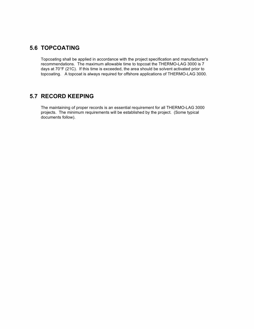
5.6 TOPCOATING
Topcoating shall be applied in accordance with the project specification and manufacturer's recommendations. The maximum allowable time to topcoat the THERMO-LAG 3000 is 7 days at 70°F (21C). If this time is exceeded, the area should be solvent activated prior to topcoating. A topcoat is always required for offshore applications of THERMO-LAG 3000.
5.7 RECORD KEEPING
The maintaining of proper records is an essential requirement for all THERMO-LAG 3000 projects. The minimum requirements will be established by the project. (Some typical documents follow).
24
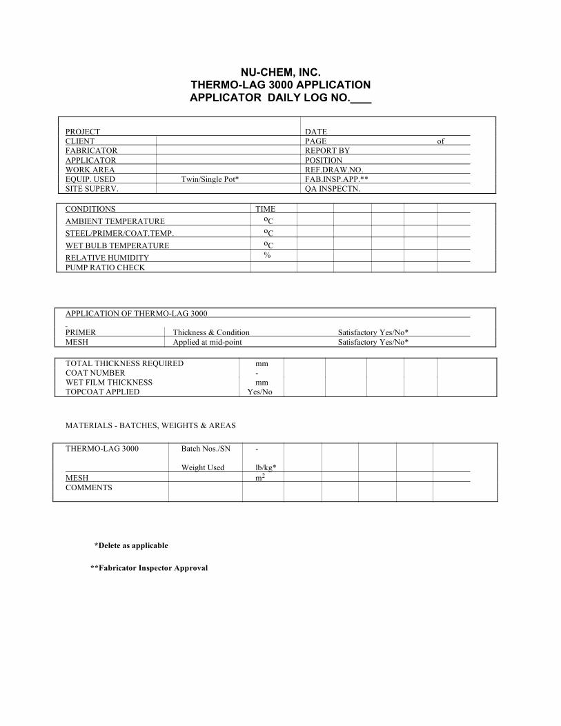
NU-CHEM, INC. THERMO-LAG 3000 APPLICATION APPLICATOR DAILY LOG NO.
PROJECT DATE CLIENT PAGE of FABRICATOR REPORT BY APPLICATOR POSITION WORK AREA REF.DRAW.NO. EQUIP. USED Twin/Single Pot* FAB.INSP.APP.** SITE SUPERV. QA INSPECTN.
CONDITIONS TIME AMBIENT TEMPERATURE oC STEEL/PRIMER/COAT.TEMP. oC WET BULB TEMPERATURE oC RELATIVE HUMIDITY % PUMP RATIO CHECK
APPLICATION OF THERMO-LAG 3000 PRIMER Thickness & Condition Satisfactory Yes/No* MESH Applied at mid-point Satisfactory Yes/No*
TOTAL THICKNESS REQUIRED mm COAT NUMBER - WET FILM THICKNESS mm TOPCOAT APPLIED Yes/No
MATERIALS - BATCHES, WEIGHTS & AREAS
THERMO-LAG 3000 Batch Nos./SN - Weight Used lb/kg* MESH m2 COMMENTS
*Delete as applicable
**Fabricator Inspector Approval
25
NU-CHEM, INC. THERMO-LAG 3000 APPLICATION
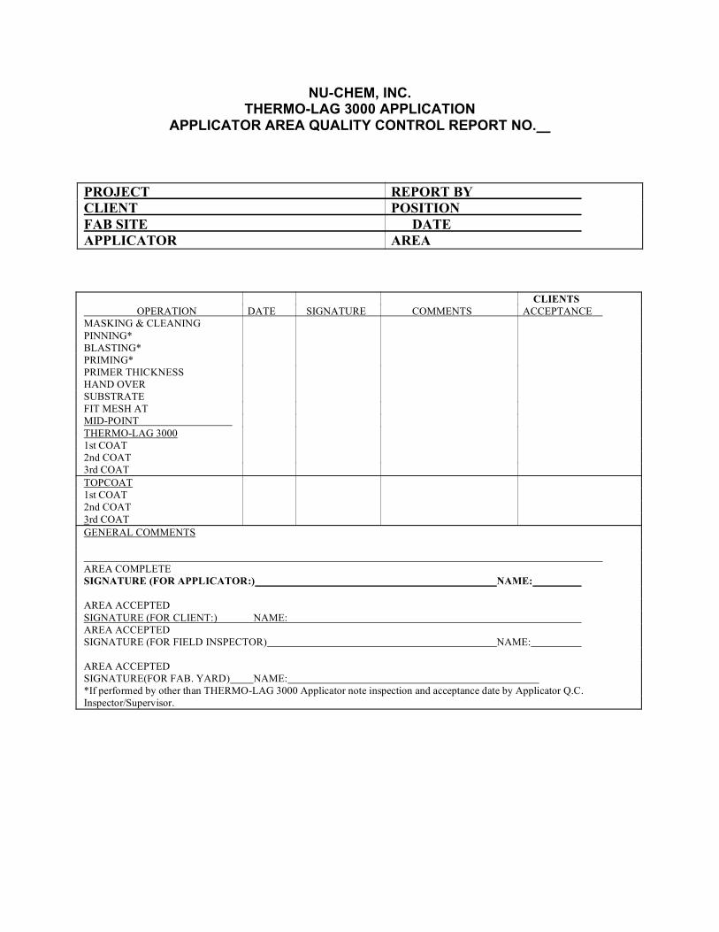
APPLICATOR AREA QUALITY CONTROL REPORT NO.
PROJECT REPORT BY CLIENT POSITION FAB SITE DATE APPLICATOR AREA
CLIENTS OPERATION DATE SIGNATURE COMMENTS ACCEPTANCE MASKING & CLEANING PINNING* BLASTING* PRIMING* PRIMER THICKNESS HAND OVER SUBSTRATE FIT MESH AT MID-POINT THERMO-LAG 3000 1st COAT 2nd COAT 3rd COAT TOPCOAT 1st COAT 2nd COAT 3rd COAT GENERAL COMMENTS AREA COMPLETE SIGNATURE (FOR APPLICATOR:) NAME: AREA ACCEPTED SIGNATURE (FOR CLIENT:) NAME: AREA ACCEPTED SIGNATURE (FOR FIELD INSPECTOR) NAME: AREA ACCEPTED SIGNATURE(FOR FAB. YARD) NAME: *If performed by other than THERMO-LAG 3000 Applicator note inspection and acceptance date by Applicator Q.C. Inspector/Supervisor.

26
NU-CHEM, INC. THERMO-LAG 3000 APPLICATION
APPLICATOR WEEKLY STATUS REPORT NO.
PROJECT REPORT BY CLIENT POSITION FAB SITE DATE APPLICATOR PAGE of
REPORT/LOG REFERENCES
AREA QC DAILY LOGS REPORTS FIELD SERVICE AUDIT NON-CONFORMANCE
AREAS COATED MODULE/LOCATION AREA COATED SQUARE METERS QUALITY ACHIEVED GENERAL COMMENTS
SIGNED APPLICATOR SIGNED FOR CLIENT SIGNED FOR FIELD INSPECTOR__________________________________________________ SIGNED FAB. YARD

27
NU-CHEM, INC.
THERMO-LAG 3000 APPLICATION
NON-CONFORMANCE REPORT NO.
PROJECT REPORT BY CLIENT POSITION FAB SITE DATE APPLICATOR PAGE of
REPORT/LOG REFERENCES APPLICABLE DAILY LOGS AREA QC REPORTS FIELD SERVICE AUDIT NON-CONFORMANCE
MODULE/LOCATION AREA INVOLVED SQUARE METERS DEFECTS NOTED: ACTION REQUIRED:
SIGNED SIGNED FIELD INSPECTOR FAB YARD SIGNED SIGNED APPLICATOR CLIENT SIGNED
28
NU-CHEM, INC. THERMO-LAG 3000 APPLICATION
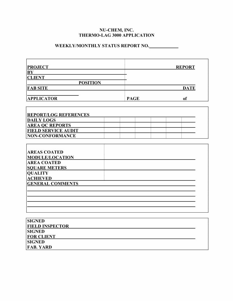
WEEKLY/MONTHLY STATUS REPORT NO.
PROJECT REPORT BY CLIENT POSITION FAB SITE DATE APPLICATOR PAGE of
REPORT/LOG REFERENCES DAILY LOGS AREA QC REPORTS FIELD SERVICE AUDIT NON-CONFORMANCE
AREAS COATED MODULE/LOCATION AREA COATED SQUARE METERS QUALITY ACHIEVED GENERAL COMMENTS SIGNED FIELD INSPECTOR SIGNED FOR CLIENT SIGNED FAB. YARD
29
6.0 CLEAN-UP
The application area shall be maintained in a clean and orderly condition following the application, all overspray, debris, and equipment shall be removed and the area left in a condition acceptable to the Owner and Main Contractor.
7.0 REMOVAL AND REPAIR PROCEDURES
7.1 REMOVAL
The preferred method is to cut through the THERMO-LAG 3000 at right angles to the substrate with a disc saw, making sure that the steel substrate is not damaged, completely around the area to be removed. A power chisel can then be used to “chip” away the THERMO-LAG 3000 from the substrate.
It is essential that proper safety precautions are taken during this operation. Reference shall be made to the THERMO-LAG 3000 Material Safety Data Sheets (MSDS).
7.2 REPAIRS - GENERAL
In instances when THERMO-LAG 3000 has been damaged or is in need of repairs the following procedures shall be followed:
The primer system shall be reinstated to its original specification.
Remove all damaged material back to solidly adhered material. Bevel all edges so as to expose a 25mm (1") band of reinforcement around the perimeter of the damaged material. All edges must be solvent cleaned and allowed to dry before commencing application of THERMO-LAG 3000.
The THERMO-LAG 3000 shall be trowel or spray applied to the midpoint of the specified thickness. The fibreglass mesh shall be applied so as to achieve a minimum of a 25mm (1”) overlap in the repaired area and to the project specification. The final specified thickness of THERMO-LAG 3000 can then be applied.
It is important that the repair blends into the original material to achieve a uniform appearance.
The topcoat shall be applied to the original specification.
NOTE: This is a general Application Manual and cannot cover all possible situations, which may arise in the field. For technical assistance, NU-CHEM, Inc. should be contacted and all variances must be approved by NU-CHEM, Inc. and the Owner.