thermally conductive separator with hierarchical...
TRANSCRIPT

Available online at www.sciencedirect.com
journal homepage: www.elsevier.com/locate/nanoenergy
Nano Energy (2016) 22, 301–309
http://dx.doi.org/12211-2855/& 2016 E
nCorresponding aUnited States.
nnCorresponding aE-mail addresses
FULL PAPER
Thermally conductive separatorwith hierarchical nano/microstructuresfor improving thermal managementof batteries
Yuan Yanga,b,n, Xiaopeng Huanga, Zeyuan Caob, Gang Chena,nn
aDepartment of Mechanical Engineering, Massachusetts Institute of Technology, Cambridge, MA 02139,United StatesbMaterials Science and Engineering, Department of Applied Physics and Applied Mathematics, ColumbiaUniversity, New York, NY 10027, United States
Received 23 October 2015; received in revised form 20 January 2016; accepted 28 January 2016Available online 21 February 2016
KEYWORDSThermal conduction;Batteries;Nanocomposite
0.1016/j.nanoen.2lsevier Ltd. All rig
uthor at: Departm
uthor.: yy2664@columbi
AbstractThermal management is critical to improving battery performance and suppressing thermalrunaway. Besides developing external cooling technologies, it is important to understand andcontrol thermal transport inside batteries. In this paper, heat transfer inside batteries is firstanalyzed and the thermal conductivity of each component is measured. The results show thatlow thermal conductivity of the separator is one major barrier for heat transfer in Li-ionbatteries. To improve thermal conductivity of the separator, a hierarchical nano/micro-Al2O3/polymer separator is prepared with thermal conductivity of �1 W m�1 K�1, representing anenhancement of 5� compared to commercial polyethylene-based separators. Modeling hasbeen performed to understand mechanism behind the enhancement of thermal conductivity,which suggests that addition of nanoparticles significantly reduces thickness of polymer coatingon micron-sized Al2O3 particles and thus increase the thermal conductivity of the compositeseparator. This Al2O3-based separator also has similar ionic conductivity with commercialpolymer separators. Such composite separator may have potential applications in developingbatteries with better performance and safety.& 2016 Elsevier Ltd. All rights reserved.
016.01.026hts reserved.
ent of Mechanical Engineering, Massachusetts Institute of Technology, Cambridge, MA 02139,
a.edu (Y. Yang), [email protected] (G. Chen).

Y. Yang et al.302
Introduction
High-performance batteries are important for various appli-cations ranging from portable electronics, electric vehiclesand grid-level energy storage [1,2]. Thermal managementof state-of-the-art Li-ion batteries (LIBs) and future higherenergy batteries is critical to their performance and safety,especially at large scale [3–6]. The high temperaturesignificantly deteriorates cycle life and it is one importantreason to trigger thermal runaway, especially for batterieswith high energy and power density [7–10]. Past effortsmainly focus on modeling of external cooling technologies,such as forced air and liquid cooling, to lower batterytemperature [5,11–19], where the lumped heat transfermodel is widely used without considering thermal conduc-tivity (k) of a battery itself [15–18]. Only a few referencestook battery thermal conductivity into account withassumed values [5,11,19]. Improving thermal transportinside batteries can also facilitate heat dissipation, reducetemperature inhomogeneity and thermal stress in batteries.In this paper, we first measured thermal conductivity ofdifferent components in batteries and identified that thebattery separator is a major limiting factor for heatdissipation in batteries. Then a thermally conductiveAl2O3/polymer composite separator was developed toimprove heat dissipation in batteries. The Al2O3/polymerhybrid separator contains both micron-sized and nano-sizedAl2O3 particles as the thermally conductive phase, and Poly(vinylidene fluoride-hexafluoropropylene) (PVdF-HFP) as thebinder. The large surface area of nanoparticles reducesthickness of polymer coating on Al2O3 and enhances thermalconductivity of the separator. At the optimized materialsloading ratio, a thermal conductivity of 1.0570.16 W m�1
K�1 is reached, which is more than five times that ofcommercial polyethylene/polypropylene (PE/PP)-basedcommercial separator. Such separators could improve heatconduction and reduce the temperature rise of batteries inoperations. Meanwhile, the composite separator showssimilar ionic conductivity as commercial polyethylene-based separators, avoiding excessive joule heating due toslower ionic transport across the separator.
Materials and methods
Materials
Micro-Al2O3 particles (�10 μm) were purchased from SigmaAldrich. Kynar 2801 PVdF-HFP was received from Arkema.Commercial single-side coated LiCoO2 and graphite electro-des, separators and nano-Al2O3 particles (�100 nm) werepurchased from MTI Corporation. The Al2O3/PVdF-HFP com-posite separator was prepared by dispersing micro-Al2O3
particles, nano-Al2O3 particles and PVdF-HFP binders in THFfor 12 h and drop casting onto a flat glass substrate. A moldmade of Aluminum is used to confine the dispersion andshape the separator to the desired dimension. The typicalsample size is 3 cm by 3 cm. The weight ratio of PVdF-HFPto THF is fixed as 1:11. The ratio of PVdF-HFP to Al2O3 variesfrom 20: 80 to 10: 90. After drying, the Al2O3/PVdF-HFP filmis peeled off from the glass substrate and pressed under0.1 ton for 5 min at room temperature.
Cross-plane thermal conductivity measurement
The thermal conductivity is measured by stacking multipleelectrode films together to ensure that thermal resistanceof sample is one order of magnitude higher than the thermalcontact resistance between copper and sample. After theenvironmental temperature is stabilized, the thermoelec-tric plate cools the bottom side of the sample while theheater is used to keep temperature of the top surface thesame as the environment. The heater power (Q) is recordedafter temperature is stabilized, indicated as the averagepower over 30 s after stabilization. Temperature data isrecorded by K-type thermocouple. More details can befound in Section 2 of the supporting information.
Ionic conductivity measurement
Ionic conductivity is measured by sandwiching the separatorbetween two pieces of stainless steel with the same size andapplying an AC voltage with amplitude of 10 mV at 50 kHz.The electrolyte is 1 M LiClO4 in Ethylene carbonate/Diethylcarbonate (EC:DEC) with weight ratio of 1:1.
COMSOL simulation
In simulation of temperature rise, external heat transfercoefficient is assumed to be 1000 W m�1 K�1 and 20 W m�1
K�1 for forced liquid cooling and force air cooling, respec-tively. The voltage loss due to internal resistance is sup-posed to be 0.6 V. The simulation time for 3 C rate is 1200 s.The capacity of 18650 cell is set to 3.1 Ah. Liquid cooling isapplied to all surfaces. For prismatic cells, the volumetricenergy density is set to 600 W h L�1 for the all cells. Moredetails can be found in Section 4 in the supportinginformation.
Results and discussions
A typical Li-ion battery is made up of a triple-layer structurewith a porous separator sandwiched between two compositeelectrodes (Figure 1a). The porous separator is typicallymade of polypropylene and polyethylene [20], while twoelectrodes are mixtures of active materials (e.g. LiCoO2 orgraphite, �80–95 wt%), carbon black (2–10 wt%) and poly-meric binder (1–10 wt%) (See Figure S1 for SEM images ofelectrodes and separators). The triple-layer structure isassembled together to form either a roll in a cylindrical cellor a cuboid in a prismatic cell (Figure 1b). Voids inelectrodes and separators are filled with carbonate-basedorganic electrolyte. In battery operation, heat is generatedthroughout the cell due to joule heat and entropy change inelectrochemical processes [21]. The heat produced is firstconducted inside the cell through both in-plane and cross-plane directions of the triple-layer structure, followed bydissipation process outside the cell, such as air/liquidconvection (Figure 1b). The in-plane direction of thetriple-layer structure corresponds to the axial direction incylindrical cells and width/length directions in prismaticcells with a thermal conductivity of k==, while the cross-plane direction corresponds to the radial direction incylindrical cells and thickness direction in prismatic cells

Nomenclature
A Cross-section area of a sample, or a battery,surface area for convection
h Heat transfer coefficientk Thermal Conductivity of the sample
(W m�1 K�1)k┴ Cross-plane thermal conductivity of a battery
component saturated with DEC (W m�1 K�1)k== In-plane thermal conductivity of a battery com-
ponent saturated with DEC (W m�1 K�1)
kAl2O3 ;polymer The effective thermal conductivity of anAl2O3 particle coated with PVdF-HFP(W m�1 K�1)
keff Effective thermal conductivity of an Al2O3/poly-mer composite with DEC (W m�1 K�1)
k┴;separator Cross-plane thermal conductivity of a separa-tor (W m�1 K�1)
l Heat transport distanceTrise temperature rise due to heating inside batteriesΔx Thickness of the sample (m)λ Volume portion of a certain phase
Figure 1 The structure of common Li-ion batteries and heat dissipation. (a) A typical Li-ion battery consists of three layers:composite cathode (e.g. LiCoO2) with Al as the substrate, porous separator, and composite anode (e.g. graphite) with Cu as thesubstrate. The cross-plane heat transport is mainly limited by thermal resistance of the separator layer due to its low thermalconductivity. (b) Heat transfer in both in-plane and cross-plane directions of the triple-layer structure inside batteries, and thendissipate through convection outside batteries.
303Thermally conductive separator with hierarchical nano/microstructures
with a thermal conductivity of k┴. To understand limitingfactors for heat dissipation in batteries, thermal conductiv-ity of battery components is measured first, followed byestimation of thermal resistance of different directions andexternal convection.
The first step in our analysis is to obtain thermalconductivity of electrodes and separators by experimentalmeasurements. In the past, Maleki et al used laser flashmethod to measure k┴ and k== of electrodes and the triple-layer structure at different state-of-charge [22]. Theirresults show that k┴ of electrodes and trilayer are �3 Wm�1 K�1 when saturated with electrolyte, while k== is 20–30 W m�1 K�1. However, a single-layer model is applied tomulti-layer samples with distinct thermal properties in theirstudy. In this report, k┴ of electrodes and separators aremeasured by a differential steady state method, as
discussed in our previous work [23] (Figure 2a), which usesheat flux applied to the sample, temperature differenceacross the sample and sample geometry to derive k┴ basedon the Fourier’s law. To reduce the effect of contactthermal resistance, multiple layers of battery electrodesor separators are stacked together so that the thermalresistance of sample (�1� 10�3 m2 K W�1) is much largerthan contact resistance between copper plates and thesample (�1� 10�4 m2 K W�1). To mimic a real battery, wefocus on electrodes and separators saturated with diethylcarbonate (DEC), one major component in LIB electrolyte.No salt is added since it contributes little to thermalconductivity [24] and it is sensitive to moisture. k┴ ofLiCoO2 electrode, graphite electrode and separators satu-rated with DEC are measured to be 1.0670.16, 2.070.3,and 0.1970.03 W m�1 K�1 (Table 1), which are in the same

Table 1 Measured thermal properties of electrodes andseparators in batteries.
Positive Negative Separator
Electrode material LiCoO2 Graphite PP/PE/PPSubstrate 15 μm Al 9 μm Cu N/AThickness of active
materials (μm)82 106 24
Cross-plane thermalconductivity withDEC(k┴, W m�1 K�1)a
2.070.3 1.0670.16 0.1970.03
Effective in-planethermal conductiv-ity(k==, W m�1 K�1)a
28 31 0.1970.03
aWith metal substrate taken into account for both positiveand negative electrodes.
Figure 2 Measurements and simulations of heat transfer in Li-ion batteries. a) A schematic of the differential steady state methodto measure thermal conductivity. A thermoelectric (TE) cooler cools the bottom side of a sample with a thickness of Δx while a thinfilm heater keeps top surface at the same temperature as the environment, which minimizes heat loss to the environment andimproves accuracy of measured heat flux through the sample. Copper plates are used to realize uniform temperature distribution attwo ends of the sample, which are measured by thermocouples (TCs). b) and c) Calculated thermal resistances of b) the cylindricalcell configuration and c) the prismatic cell configuration. The cylindrical cell dimension is scaled from an 18650 cell. The definitionof directions in b) and c) is the same as Figure 1b. Symbols in parenthesis indicate corresponding thermal conductivity in thedirection. d) Numerical simulation by COMSOL Multiphysics on temperature rise against thermal conductivity of separator in a four-prismatic-cell pack and a 18650 cell, respectively. e) Corresponding temperature distribution in the cross section of an 18650 cellwith the same simulation described in (d). The cross section passes the central axis of the cylindrical cell.
Y. Yang et al.304
order of previous results by the laser flash method [22]. Thein-plane thermal conductivities (k==) of electrodes aredominated by metal substrates (Al for LiCoO2 and Cu forgraphite), so k// of electrodes are calculated based on the
literature values [25] on thermal conductivity of metals. k==of the separator is considered to be the same as k┴. Detailsof experimental procedures and calculations can be found inSections 2 and 3 in the supporting information.
The next step in our study is to estimate thermalresistance and heat generation/dissipation in batteries tounderstand the limiting factor. Two cell geometries areconsidered. One is the cylindrical cell scaled from 18650cells with height of 65 mm and diameter of 18 mm, whichmeans that the ratio of height to diameter is kept at 65/18.Another geometry is stacked prismatic cells where a singlecell has two sides of 216 and 290 mm, respectively, andthickness of 7 mm. This dimension is the same as that usedin Nissan leaf [26]. Thermal resistances along differentdirections are simply estimated based on one-dimensionalheat conduction along the corresponding direction. It isdefined as ΔT/Q at steady state with uniform heat genera-tion inside the cell, where ΔT is the temperature differencebetween the center and surface of the cell, and Q is totalheat transferred at cell surface. In calculation, the thermalconductivity along a direction in the cell is supposed to bethe same as the effective thermal conductivity of the triplelayer along the same direction, since the thickness of atriple layer (200–300 μm) is much smaller than the celldimension (45 mm). The thermal resistance of externalheat transfer is estimated as 1=hA, where h is the heat

Figure 3 Micro-Al2O3/PVdF-HFP composite separator. a) A schematic of micro-Al2O3/PVdF-HFP composite to improve thermalconductivity of a separator. b) and c) Optical and SEM images of the composite separators. The particle size is �10 μm. The weightratio of micro-Al2O3 to PVdF-HFP is 85:15. d) Cross-plane thermal conductivity of the micro-Al2O3/PVdF-HFP separator.
Table 2 Properties of micro-Al2O3/PVdF-HFP and com-mercial separators.
Al2O3:PVdF-HFP(weight)
80:20 85:15 90:10 Commercial PP/PE/PP Separator
Density (g cm�3) 1.83 1.93 2.0 0.57Volumetric Por-
tion of Solid0.58 0.58 0.56 0.61a
Ionic Conductiv-ity (mS cm�1)
0.64 0.68 0.75 0.88
Thickness (μm) 30–200 25
aBased on porosity of 0.39.
305Thermally conductive separator with hierarchical nano/microstructures
transfer coefficient, and A is the surface area for externalconvection.
Calculation results are shown as Figure 2b and c forcylindrical and prismatic cell configuration, respectively.Although k┴ is much smaller than k== in batteries, the totalthermal resistance along the cross-plane direction is actu-ally smaller, as the cross-plane direction has larger crosssectional area and smaller length for heat transfer. Thisindicates that heat dissipation along the cross-plane direc-tion is actually more efficient than in-plane. Regardless ofcell geometry and dimension, thermal resistance of forcedliquid cooling is much less than the cell, as h of liquid is veryhigh, typically in the order of 1000 W m�2 K�1 [27], whichindicates that heat dissipation is limited by the cell itselfunder forced liquid cooling. In the scenario of forced aircooling, thermal resistance of air convection is the limitingfactor instead of heat conduction inside a cell, as h offorced convective air is only �20 W m�2 K�1 [27]. There-fore, improving k┴ of the triple layer structure in batteriescan effectively enhance total heat dissipation in batteries,especially when forced liquid cooling is used. Furtheranalysis shows that the separator layer counts for 46% oftotal cross-plane thermal resistance of the triple-layerstructure (Section 3 in Supporting information), while theLiCoO2 and graphite electrodes contribute 33% and 21%,respectively; thus the key to enhance heat dissipation is toincrease the separator’s cross-plane thermal conductivity(k┴;separator).
To further validate this argument, COMSOL simulationwas carried out to understand the effect of k┴;separator ontemperature rise (Trise) of a battery in operation. Forexample, Under 3 C rate (charge or discharge in 1/3 h)and forced liquid cooling, Trise at the end of discharge in afour-prismatic-cell pack and a single 18650 cell decreasesfrom 40 1C to 27 1C and from 8 1C to 6 1C, respectively, whenk┴;separator increases from 0.185 W m�1 K�1 to 1 W m�1 K�1.These values correspond to reduction of 33% and 25% inTrise, respectively. Higher thermal conductivity of separatoralso leads to more uniform temperature distribution insidethe cell, as illustrated in temperature distribution of thecell cross section (Figure 2e and S4). The more uniform
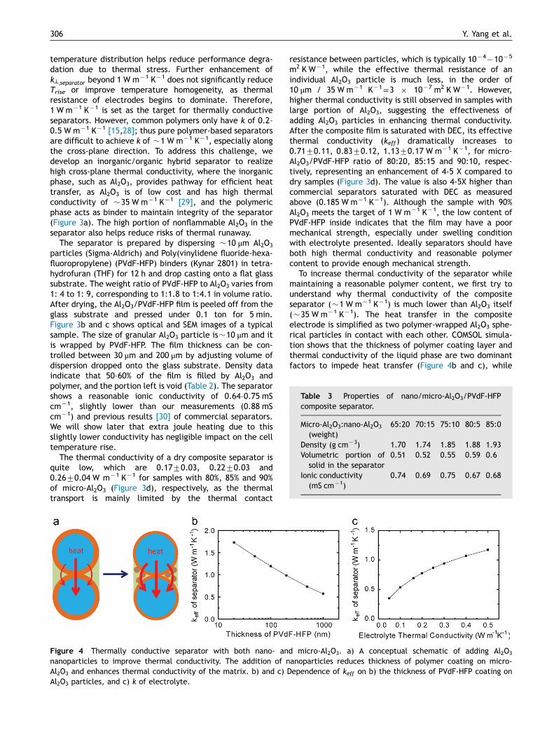
Table 3 Properties of nano/micro-Al2O3/PVdF-HFPcomposite separator.
Micro-Al2O3:nano-Al2O3
(weight)65:20 70:15 75:10 80:5 85:0
Density (g cm�3) 1.70 1.74 1.85 1.88 1.93Volumetric portion of
solid in the separator0.51 0.52 0.55 0.59 0.6
Ionic conductivity(mS cm�1)
0.74 0.69 0.75 0.67 0.68
Y. Yang et al.306
temperature distribution helps reduce performance degra-dation due to thermal stress. Further enhancement ofk┴;separator beyond 1 W m�1 K�1 does not significantly reduceTrise or improve temperature homogeneity, as thermalresistance of electrodes begins to dominate. Therefore,1 W m�1 K�1 is set as the target for thermally conductiveseparators. However, common polymers only have k of 0.2–0.5 W m�1 K�1 [15,28]; thus pure polymer-based separatorsare difficult to achieve k of �1 W m�1 K�1, especially alongthe cross-plane direction. To address this challenge, wedevelop an inorganic/organic hybrid separator to realizehigh cross-plane thermal conductivity, where the inorganicphase, such as Al2O3, provides pathway for efficient heattransfer, as Al2O3 is of low cost and has high thermalconductivity of �35 W m�1 K�1 [29], and the polymericphase acts as binder to maintain integrity of the separator(Figure 3a). The high portion of nonflammable Al2O3 in theseparator also helps reduce risks of thermal runaway.
The separator is prepared by dispersing �10 μm Al2O3
particles (Sigma-Aldrich) and Poly(vinylidene fluoride-hexa-fluoropropylene) (PVdF-HFP) binders (Kynar 2801) in tetra-hydrofuran (THF) for 12 h and drop casting onto a flat glasssubstrate. The weight ratio of PVdF-HFP to Al2O3 varies from1: 4 to 1: 9, corresponding to 1:1.8 to 1:4.1 in volume ratio.After drying, the Al2O3/PVdF-HFP film is peeled off from theglass substrate and pressed under 0.1 ton for 5 min.Figure 3b and c shows optical and SEM images of a typicalsample. The size of granular Al2O3 particle is�10 μm and itis wrapped by PVdF-HFP. The film thickness can be con-trolled between 30 μm and 200 μm by adjusting volume ofdispersion dropped onto the glass substrate. Density dataindicate that 50–60% of the film is filled by Al2O3 andpolymer, and the portion left is void (Table 2). The separatorshows a reasonable ionic conductivity of 0.64–0.75 mScm�1, slightly lower than our measurements (0.88 mScm�1) and previous results [30] of commercial separators.We will show later that extra joule heating due to thisslightly lower conductivity has negligible impact on the celltemperature rise.
The thermal conductivity of a dry composite separator isquite low, which are 0.1770.03, 0.2270.03 and0.2670.04 W m�1 K�1 for samples with 80%, 85% and 90%of micro-Al2O3 (Figure 3d), respectively, as the thermaltransport is mainly limited by the thermal contact
Figure 4 Thermally conductive separator with both nano- annanoparticles to improve thermal conductivity. The addition of nAl2O3 and enhances thermal conductivity of the matrix. b) and c)Al2O3 particles, and c) k of electrolyte.
resistance between particles, which is typically 10�4�10�5
m2 K W�1, while the effective thermal resistance of anindividual Al2O3 particle is much less, in the order of10 μm / 35 W m�1 K�1=3 � 10�7 m2 K W�1. However,higher thermal conductivity is still observed in samples withlarge portion of Al2O3, suggesting the effectiveness ofadding Al2O3 particles in enhancing thermal conductivity.After the composite film is saturated with DEC, its effectivethermal conductivity (keff) dramatically increases to0.7170.11, 0.8370.12, 1.1370.17 W m�1 K�1, for micro-Al2O3/PVdF-HFP ratio of 80:20, 85:15 and 90:10, respec-tively, representing an enhancement of 4-5 X compared todry samples (Figure 3d). The value is also 4-5X higher thancommercial separators saturated with DEC as measuredabove (0.185 W m�1 K�1). Although the sample with 90%Al2O3 meets the target of 1 W m�1 K�1, the low content ofPVdF-HFP inside indicates that the film may have a poormechanical strength, especially under swelling conditionwith electrolyte presented. Ideally separators should haveboth high thermal conductivity and reasonable polymercontent to provide enough mechanical strength.
To increase thermal conductivity of the separator whilemaintaining a reasonable polymer content, we first try tounderstand why thermal conductivity of the compositeseparator (�1 W m�1 K�1) is much lower than Al2O3 itself(�35 W m�1 K�1). The heat transfer in the compositeelectrode is simplified as two polymer-wrapped Al2O3 sphe-rical particles in contact with each other. COMSOL simula-tion shows that the thickness of polymer coating layer andthermal conductivity of the liquid phase are two dominantfactors to impede heat transfer (Figure 4b and c), while
d micro-Al2O3. a) A conceptual schematic of adding Al2O3
anoparticles reduces thickness of polymer coating on micro-Dependence of keff on b) the thickness of PVdF-HFP coating on

Figure 5 keff of the composite separator calculated by theBruggeman's model. a) Micro-Al2O3/PVdF-HFP compositeseparators. b) Nano/micro-Al2O3/PVdF-HFP composite separa-tors. The weight percentage of PVdF-HFP is fixed as 15%.
307Thermally conductive separator with hierarchical nano/microstructures
other factors, such as interfacial thermal conductance andcontact area, have little effect on the effective thermalconductivity (Figure S5). Based on simulation results, weproposed to replace certain amount of micron-sized Al2O3
(micro-Al2O3) particles with nanoparticles (nano-Al2O3) toaddress the two dominant factors discussed above. First,the large surface area of nanoparticles helps reduce thethickness of polymer layer on Al2O3 as polymer is assumed tobe uniformly coated onto all Al2O3 particles. Second,nanoparticles could distribute in the gap among largeAl2O3 particles to improve heat transfer in the DEC matrix.
Based on the argument above, composite separators with10 μm Al2O3, 100 nm Al2O3 and PVdF-HFP are prepared withthe same procedure as samples without nano-Al2O3. Theweight portion of PVdF-HFP is fixed to be 15 wt% (28.1 vol%)of all solids. The SEM image shows that Al2O3 nanoparticlesdistribute among micro-Al2O3 particles and they are gluedby PVdF-HFP (Figure S6b), which is similar with observationsin composite battery electrodes [31]. Further analysis, suchas 3D imaging by synchrotron, could help us understand thedistribution and connectivity of particles in the composite.The ionic conductivity of samples with nano-Al2O3 is
comparable to samples without nano-Al2O3, suggesting thatthe addition of nanoparticles does not apparently affectionic transport (Table 3). Experimental results on thermalconductivity are illustrated in Figure 4b. For dry samples,the thermal conductivity is basically the same as thosewithout nano-Al2O3 in Figure 3d, as the thermal transport isstill limited by contact resistance. After saturating thecomposite with DEC, the thermal conductivity increasesfirst as the content of nano-Al2O3 becomes higher, from0.8170.12 W m�1 K�1 with 0 wt% nano-Al2O3 to1.0570.16 W m�1 K�1 with 15 wt% nano-Al2O3, which isconsistent with our prediction and meets the goal of1 W m�1 K�1. However, the thermal conductivity dropsdown when the content of nano-Al2O3 is over 20 wt% inthe solid phase. This may arise from the fact that micro-Al2O3 particles are separated by nano-Al2O3 particles andthey no longer form a network to efficiently conduct heat atlow portion of micro-Al2O3.
To better understand thermal transport in the compositeand help future development, we use effective mediumtheory to model the dependence of keff on separatorcomposition. The Bruggeman's model with spherical inclu-sion is used here and it is applied to micro-Al2O3/PVdF-HFPseparator saturated with DEC first. The Bruggeman’s model[32] indicates thatX
λiki�keffkiþ2keff
¼ 0 ð1Þ
where λ is the volume portion and subscript i meansdifferent phases in the composite. As PVdF-HFP is coatedonto Al2O3 particles, two phases exist: PVdF-HFP wrappedAl2O3 and DEC. The effective thermal conductivity of aPVdF-HFP wrapped Al2O3 particle (kAl2O3 ;polymer)) is calcu-lated based on following assumptions and approximations:1) all PVdF-HFP is uniformly coated onto Al2O3 particles andthe shape of Al2O3 particle is spherical. 2) The thermalresistance of the particle is that of Al2O3 and PVdF-HFP inseries. Interfacial thermal resistance between DEC and solidis neglected as it is typically much smaller than thermalresistances of micro-Al2O3 particles (10�7�10�8 m2 K W�1
vs. 10�6 �10�4 m2 K W�1) [29]. k used in calculations are35 W m�1 K�1 for micro-Al2O3, 0.19 W m�1 K�1 for PVdF-HFP and 0.16 W m�1 K�1 for DEC [33].
keff of the micro-Al2O3/PVdF-HFP composite separatorpredicted by the Bruggeman’s model fits well with experi-mental results (Figure 5a). We further apply the model tocalculate keff of nano/micro-Al2O3/PVdF-HFP composite. Insuch a composite, three phases exist: PVdF-HFP wrappedmicro-Al2O3, PVdF-HFP wrapped nano-Al2O3 and DEC.Besides assumptions used in the micro-Al2O3/PVdF-HFPcomposite above, the thickness of PVdF-HFP on bothmicro-Al2O3 and nano-Al2O3 are assumed to be the same,and k of nano-Al2O3 is supposed to be 12 W m�1 K�1 to takesize-dependent thermal conductivity into account [29].However, the predicted values are 50–100% higher thanexperimental results (Figure 5b). This suggests that theassumption of uniform coating of PVdF-HFP on both nano-Al2O3 and micro-Al2O3 may not be valid. It is well knownthat nanoparticles tend to agglomerate due to stronginteraction among themselves. Therefore it is speculatedthat there is less PVdF-HFP on nano-Al2O3 than the welldispersed situation; thus the thickness of PVdF-HFP on

Figure 6 Stability of Al2O3/polymer separator against lithium metal. The composite separator is attached to lithium and soaked in1 M LiPF6 in EC/DEC for seven days. (a) XRD pattern before and after contacting with Li. (b) Optical image of a composite separatorbefore and after contacting with Li. No change has been observed. It is supposed that polymer coating effectively block directreaction between lithium and Al2O3.
Y. Yang et al.308
micro-Al2O3 is larger than that in uniform coating, whichgives a lower keff than the prediction. The higher keffpredicted by the model also implies that further optimiza-tion of particle dispersion and polymer coating may boostkeff to �2 W m�1 K�1.
A concern in applying Al2O3/polymer separator to enhanceheat dissipation is that whether the lower ionic conductivityof Al2O3/polymer separator increases heat generation inbatteries and thus compensates its higher thermal conduc-tivity. Tables 2 and 3 show that the ionic conductivity ofAl2O3/polymer is �0.2 mS cm�1 lower than commercialseparators. Let us use 18650 cell as an example. The typicalthickness and size of separator in a 18650 cell are 25 μm and6� 50 cm2, respectively, it is estimated that the extra over-potential due to lower ionic conductivity is �25 mV at 3 Crate, which is only 4% of the total overpotential of �0.6 Vand has little effect on heat generation. COMSOL simulationsshow that this extra overpotential only causes an extratemperature rise of 0.27 K, which is only 12% of thetemperature reduction due to enhanced thermal conductiv-ity of separator (2.16 K). Similarly, this extra overpotentialresults in an extra temperature rise of 1.1 K for four-prismatic-cell pack discussed above, which corresponds toonly 8.5% of the temperature reduction due to enhancedthermal conductivity of separator (12.9 K). Moreover, as theporosity of Al2O3/polymer separators is similar to that ofcommercial ones, we believe that ionic conductivity of suchcomposite separators can be further improved. Anotherconcern is the mechanical strength of the separator whenit is soaked in electrolyte, as the organic electrolyte in Li-ionbatteries could swell the separator. This issue could beaddressed by replacing PVdF-HFP with other polymers withbetter mechanical properties, such as polyvinyl alcohol.
The stability of such composite separator is also tested byattaching it to a lithium metal and soak in electrolyte (1 MLiPF6 in EC/DEC) for seven days. XRD data do not show anynew peaks, and there is no obvious change in camera images(Figure 6). These results indicate that no or only traceamount of Al2O3 has reacted with lithium. We believe that
the polymer coating layer on Al2O3 avoids the direct contactbetween Al2O3 and lithium. As a result, the degree ofreaction is very limited and it should have little impact onthermal conductivity of the whole composite. Furtherinvestigation is needed to evaluate the long term stabilityof such composite separator.
Conclusion
In summary, k┴ of battery separator is important to thermalmanagement of batteries. A nano/micro-Al2O3/PVdF-HFP-based composite separator is developed with high thermalconductivity (�1 W m�1 K�1), which is �5 times that ofcommon PE-based separators. The addition of Al2O3 nano-particles helps further enhance thermal conductivity of thecomposite. The mechanism is assumed to be that Al2O3
nanoparticles help reduce thickness of polymer coating onmicro-Al2O3 and improve effective thermal conductivity ofthe electrolyte. Such thermally conductive separator couldhave potential applications to dissipate heat faster inbatteries and reduce temperature rise in operation, espe-cially under external forced liquid cooling.
Acknowledgment
We would like to thank Daniel Kraemer for developing thedifferential steady-state method to measure thermal con-ductivity and helpful discussions. This material is basedupon work supported as part of the Solid State Solar-Thermal Energy Conversion Center (S3TEC), an EnergyFrontier Research Center funded by the U.S. Departmentof Energy, Office of Science, Office of Basic Energy Sciencesunder Award number DE-SC0001299/DE-FG02-09ER46577.Yuan Yang thanks support from startup funding from Colum-bia University (Grant no. UR007667).
309Thermally conductive separator with hierarchical nano/microstructures
Appendix A. Supplementary material
Supplementary data associated with this article can befound in the online version at http://dx.doi.org/10.1016/j.nanoen.2016.01.026.
References
[1] M. Armand, J.-M. Tarascon, Nature 451 (2008) 652–657.[2] M.S. Whittingham, Chem. Rev. 104 (2004) 4271–4301.[3] S. Al Hallaj, H. Maleki, J.S. Hong, J.R. Selman, J. Power
Sources 83 (1999) 1–8.[4] T.M. Bandhauer, S. Garimella, T.F. Fuller, J. Electrochem. Soc.
158 (2011) R1–R25.[5] W.B. Gu, C.Y. Wang, Thermal-electrochemical coupled model-
ing of a lithium-ion cell, vol. 99, 2000, pp. 748–762.[6] V. Ramadesigan, P.W.C. Northrop, S. De, S. Santhanagopalan,
R.D. Braatz, V.R. Subramanian, J. Electrochem. Soc. 159(2012) R31–R45.
[7] K.-C. Chiu, C.-H. Lin, S.-F. Yeh, Y.-H. Lin, K.-C. Chen, J. PowerSources 251 (2014) 254–263.
[8] G.-H. Kim, A. Pesaran, R. Spotnitz, J. Power Sources 170(2007) 476–489.
[9] Q. Wang, P. Ping, X. Zhao, G. Chu, J. Sun, C. Chen, J. PowerSources 208 (2012) 210–224.
[10] W. Luo, L. Zhou, K. Fu, Z. Yang, J. Wan, M. Manno, Y. Yao,H. Zhu, B. Yang, L. Hu, Nano Lett. 15 (2015) 6149–6154.
[11] D.R. Baker, M.W. Verbrugge, J. Electrochem. Society 146(1999) 2413–2424.
[12] L. Fan, J.M. Khodadadi, A.A. Pesaran, J. Power Sources 238(2013) 301–312.
[13] R. Kizilel, R. Sabbah, J.R. Selman, S. Al-Hallaj, J. PowerSources 194 (2009) 1105–1112.
[14] J.M. Mottard, C. Hannay, E.L. Winandy, J. Power Sources 117(2003) 212–222.
[15] Y. Ji, C.Y. Wang, Electrochimica Acta 107 (2013) 664–674.[16] W. Fang, O.J. Kwon, C.-Y. Wang, Int. J. Energy Res. 34 (2010)
107–115.[17] L. Cai, R.E. White, J. Electrochem. Soc. 157 (2010)
A1188–A1195.[18] B. Wu, V. Yufit, M. Marinescu, G.J. Offer, R.F. Martinez-Botas,
N.P. Brandon, J. Power Sources 243 (2013) 544–554.[19] J. Xun, R. Liu, K. Jiao, J. Power Sources 233 (2013) 47–61.[20] X. Huang, J. Solid State Electrochem. 15 (2011) 649–662.[21] M. Xiao, S.-Y. Choe, J. Power Sources 241 (2013) 46–55.[22] H. Maleki, S. Al Hallaj, J.R. Selman, R.B. Dinwiddie, H. Wang,
J. Electrochem. Soc. 146 (1999) 947–954.[23] D. Kraemer, G. Chen, Rev. Sci. Instrum. 85 (2014).[24] I.M. Abdulagatov, N.D. Azizov, Int. J. Thermophys. 26 (2005)
593–635.[25] John H. Lienhard V.; IV, J.H.L., A Heat Transfer Textbook,
2011.[26] ⟨⟨http://www.hybridautocenter.com/HAC4/index.php?
option=com_hikashop&ctrl=product&task=show&cid=3&name=nissan-leaf-battery-module-model-2012-new&Itemid=605⟩⟩.
[27] H. John, iv Lienhard, J.H.L. v, A Heat Transfer Textbook,Phlogiston Press, 2015.
[28] S. Shen, A. Henry, J. Tong, R. Zheng, G. Chen, Nat. Nano-technol. 5 (2010) 251–255.
[29] A.J. Minnich, Exploring Electron and Phonon Transport at theNanoscale for Thermoelectric Energy Conversion, MIT, 2011.
[30] Y.M. Lee, J.E. Seo, N.S. Choi, J.K. Park, Electrochimica Acta 50(2005) 2843–2848.
[31] G. Liu, H. Zheng, X. Song, V.S. Battaglia, J. Electrochem. Soc.159 (2012) A214–A221.
[32] D.A.G. Bruggeman, Ann. Physik 24 (1935) 636–664.[33] X.G. Jin, J.T. Wu, Z.G. Liu, J. Pan, Fluid Phase Equilibria 220
(2004) 37–40.
Dr. Yuan Yang is an assistant professor ofmaterials science in department of appliedphysics and applied mathematics at Colum-bia University since 2015. He received his B.S. in physics at Peking University in 2007,followed by completion of Ph.D. in materi-als science and engineering at StanfordUniversity in 2012, where he works onelectrochemical energy storage. After gra-duation from Stanford University, he worked
on waste heat harvesting as a postdoc in department of mechanicalengineering at MIT until 2015. His research interests includeelectrochemical materials and devices for energy storage andconversion, thermal energy harvesting and thermal management.
Xiaopeng Huang obtained his Ph.D. fromMechanical Engineering at Iowa State Uni-versity in 2011, working on thermal trans-port in low-dimensional complex structuresincluding thermoelectric nanocomposites,carbon nanotube and biomaterials like spi-der silk. He joined the nanoengineeringgroup at MIT as a postdoctoral associate in2012. His research work in MIT includesscale-up of high thermally conductive poly-
mers and development of solar thermal aerogel receiver. Afterleaving MIT, he joined Hewlett Packard Laboratory to solve thethermal problems in development of 3D stack memory and mem-ristor by multi-scale simulation and characterization of the thermaltransport.
Zeyuan Cao is currently a postdoctoralresearcher at Columbia University. Hereceived his Ph.D. degree on mechanicalengineering from the University of Delawarein 2015. His research interests focus onenergy storage materials and devices.
Gang Chen is currently the Head of theDepartment of Mechanical Engineering andCarl Richard Soderberg Professor of PowerEngineering at MIT, and is the director ofthe "Solid-State Solar-Thermal Energy Con-version Center (S3TEC Center)" – an EnergyFrontier Research Center funded by the USDepartment of Energy. He obtained his PhDdegree from the Mechanical EngineeringDepartment, UC Berkeley, in 1993. He was
an assistant professor at Duke University, a tenured associateprofessor at UC Los Angeles, before moving to MIT. He is a fellowof AAAS, APS, and ASME. In 2010, he was elected a member of theUS National Academy of Engineering.