thermal treatment of chlorinated solvents offers...
TRANSCRIPT

Kurt D. Pennell, PhD, PE, BCEEDepartment of Civil & Environmental Engineering
Tufts UniversityJed Costanza, Kelly Fletcher, Tyler Marcet, Natalie Cápiro,
and Frank Löffler
Thermal Treatment of ChlorinatedSolvents Offers Opportunities for
Combined Remedies
Advances in Thermal Remediation Workshop University of Texas at Austin
January 8-9, 2013

Combined Remedy Scenarios
Remediation Time or Cost ($)
Soi
l or G
roun
dwat
er
Con
c.
Remediation target (e.g., MCL)
“Stalled” Remediation
2. Combine remedies (in series) to achieve remediation goals (polishing step).1
2
1. Combine remedies (in parallel) to improve effectiveness and reduce time/cost of treatment.
3. At complex sites, combine remedies in space and time to more effectively achieve remediation goals.
4. Ultimate goal is site closure; inst./eng. controls

Remediation Technologies: What’s Hot, What’s Not
Hot
Not
Bioremediation (Bioaugmentation, Biostimulation, MNA)
Thermal Treatment (electrical resistive heating, steam flushing, conductive heating, combustion)
Chemical Oxidation/Reduction (ISCO, nano)Dig and Haul (ex situ treatment/disposal)Permeable Reactive Barriers/Walls (ZVI, zeolite)Surfactant/Cosolvent FlushingSoil Vapor Extraction (SVE)/Air SpargingPump and Treat

Documented successes, and not many “failures”
Prevalence of complex and/or low permeability sites
Industry and Regulatory Acceptance: Advocates and skilled practitioners
Research Funding/Activities Limitations/failure of other technologies
Emergence of Thermal Remediation
Primary limitation is cost (ca. $2-4M for small sites), Other issues: energy/carbon, patent rights, safety

Example Chlorinated Solvent SiteGroveland (MA) Superfund Site
ERH+Steam Treatment of TCE Source Zone

6
Groveland Superfund Site Timeline
http://cfpub.epa.gov/supercpad/cursites/csitinfo.cfm?id=0100750
• 1979: TCE detected in town water supply wells• 1983: NPL Listing• 1992: PRP installed SVE system• 2000: EPA-funded groundwater extraction,
treatment, discharge system installed• 2002: PRP abandoned site, SVE closed • 2008: Extracted and treated a total of 388 MG
water and recovered 1,100 lbs VOCs• 2010: Thermal Remediation: Steam+ERH, ca. $3M

Petroleum Hydrocarbon Remediation
Oil Lakes in Kuwait (first Gulf war,1990-1991)
United Nations Environmental
Program (UNEP)(e.g., Nigeria)

Category Hot Water Injection
Steam Injection
Conductive Heating
Electrical Resistive Heating
Electro-magneticHeating
Heat Transfer Convective Convective Conductive Conductive Radiative
Energy Source Hot Water Steam Steel Well Casing Electrical Electromagnetic
Temp. Limit 100oC 100-120oC 100-800oC 100-120oC 100-300oC
Technology Example
Contained Recovery of Oily Waste (CROW)
Steam Enhanced
Remediation (SER)
In-Situ Thermal
Desorption (ISTD)
Three/Six-Phase
Heating (SPH)
Microwave; Radio
Frequency
AdvantagesNo Phase
Change, Low Cost
High Perm Zones,
Energy Efficient
Low Volatility Contaminants
Lower Cost, Low Perm.
Zones
Uniform Heating, Low
Perm.
LimitationsPreferential Flow, Low Efficiency
Pref. Flow, Cost, DNAPL,
Safety
High Element Density, Cost, Temp, Safety
Pref. Heating, Drying, Safety
Low Energy Transfer-Drying
Field Sites: Source Zone
UGI ColumbiaBrodhead Creek
Visalia, CASRS, SC
Rocky Mtn Arsenal
Alhambra Pole
Fort Lewis, WA
Paducah, KY
Kelly AFB, SRS, Kirkland AFB
Comparison of Thermal Remediation Technologies

Self-Sustaining Treatment for Active Remediation (STAR)
(a.k.a. Smoldering Combustion)
1. Slow burning process involving oxidation of condensed phase (solid/liquid) at the fuel surface.
2. Ignition source plus air (oxygen) source; can be self-sustaining.
3. Typically applied to oils and coal tars at relatively high saturations (pilot at cresol site in NJ).
Switzer et al., 2009, ES&T, 43: 5871-5877.Pironi et al., 2011, ES&T, 45: 2980-2986.U.S. Patent No. 8,132,987; 2012.

Research Motivation
• In situ thermal treatment offers two distinct advantages relative to competing technologies • No chemical agents are introduced into the subsurface • Potential to effectively treat low-permeability, heterogeneous
subsurface formations
• However, very little was known about:• Chemical reactivity and reaction pathways• Effects of subsurface heating on microbial activity
• These knowledge gaps limit our ability to understand and improve thermal remediation technologies, and to design effective combined remedies or polishing technologies.
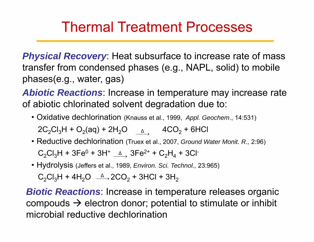
Thermal Treatment Processes
Physical Recovery: Heat subsurface to increase rate of mass transfer from condensed phases (e.g., NAPL, solid) to mobile phases(e.g., water, gas)Abiotic Reactions: Increase in temperature may increase rate of abiotic chlorinated solvent degradation due to:
• Oxidative dechlorination (Knauss et al., 1999, Appl. Geochem., 14:531)
2C2Cl3H + O2(aq) + 2H2O 4CO2 + 6HCl • Reductive dechlorination (Truex et al., 2007, Ground Water Monit. R., 2:96)
C2Cl3H + 3Fe0 + 3H+ 3Fe2+ + C2H4 + 3Cl-
• Hydrolysis (Jeffers et al., 1989, Environ. Sci. Technol., 23:965)
C2Cl3H + 4H2O 2CO2 + 3HCl + 3H2Δ
Δ
Δ
Biotic Reactions: Increase in temperature releases organic compouds electron donor; potential to stimulate or inhibit microbial reductive dechlorination

Research Objectives
• Measure physical-chemical and sorption-desorption properties of PCE and TCE as a function of temperature
• Quantify PCE and TCE reactivity and product formation as a function of temperature and system properties
• Assess the survival and activity of native, pure, and mixed consortia of dechlorinating bacteria at elevated temperatures
• Evaluate the destruction and recovery of PCE and TCE during laboratory-scale thermal treatment of field-contaminated soils
Investigate physical, chemical and biological processes governing thermal remediation of DNAPL source zones

13
C C
Cl
ClCl
Cl
C C
H
ClCl
Cl
C C
H
ClCl
H
C C
H
ClH
H
tetrachloroethlyene trichloroethylene cis-1,2-dichloroethylene vinyl chloride
H2ORadical Chain
C CY
Y
Cl
Y
O O
dioxetane
Unique Intermediate
Reactive Species
peroxyl radical
Elimination-Addition
HS-, HO-, HPO42-, HCO3
-, SO42-, NO3
-, H2O
C CY
Y
Cl
chlorovinylic anion
C CY Cl
chloroacetyleneIntermediate Products
C O
Cl
Cl
C O
C CH
Y
Cl
Y
O
C CH
Y
Cl
Y
O+
phosgene
epoxide acetyl chloride
O C O
C CHO
Y
YHO
C CHO
OH
HHOglycolic acid
T > 70oC
C CH
Y
Cl
Y
O
chloroacetyl chloride
H2O
+
chloroacetic acid
Parent Compounds
+ +
+
O2T > 70oC
Aqueous Phase Products
Gas Phase Products
Final Products
C C
Cl
Cl
H
Cl
Cl
O O
H2O or H3O+ ?H2O
O2
HCl
Y = Cl or H
OCH
HO
formic acid
+
CCH
Cl
Cl
Cl
CCCl
Cl
Cl
Cl
dichloroacetyleneClC CCl
chloroacetyleneClC CH
acetylene
HC CH
CCH
Cl
Cl
H
trans-DCE
CCH
Cl
H
Cl
cis-DCE
CCH
H
Cl
Cl
1,1-DCE
CCH
Cl
H
H
vinyl chloride
CCH
H
H
H
SRE1 Hs
Hs
EHs
Hs
Hs
Hs
SRE1
H-donor
Cl-2Cl-
Hn
Hn
Hn
C2H6ethane
PCE
TCEH-donor
HClE1cb
E1cb
E1cb
C C C C
H
H
H
H
H
H
H
H
1-butene
Hn + coupling
+cis- and trans-butene, and butadiene
SRE1
Complex Reaction Pathways-PCE/TCEOxidation Reduction

Experimental SystemsVOA vial 50 mL Ampule Microcosm-Ft Lewis Flow-Thru Reactor
1 m ERH Column

Chemical Reactivity of TCE and PCE in Heated Three-Phase Systems
Flame seal
Gas Headspace
50 mL Ampules
Solids
Aqueous Phase
Pressure Transducer
Compressed Dry Carrier Gas
MKS 179AMass Flow Meter
TCE via syringe pump
Water and Pre-MixController
25 to 100oC
Tube Oven Controller
30 to 1200oC
Tube Oven
DCM Trap Aniline Trap
Tedlar Bag
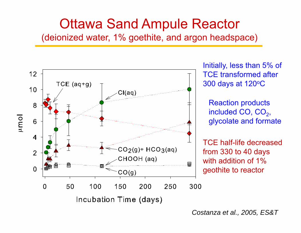
Ottawa Sand Ampule Reactor(deionized water, 1% goethite, and argon headspace)
Initially, less than 5% of TCE transformed after 300 days at 120oC
Reaction products included CO, CO2, glycolate and formate
TCE half-life decreased from 330 to 40 days with addition of 1% geothite to reactor
Costanza et al., 2005, ES&T

0
20
40
60
80
100
0 100
200
300
400
500
600
700
800
900
Reactor Temperature (oC)
Per
cent
of T
CE
Rea
ctan
t (%
)
TCE sand filled reactorPCE sand filled reactorTCE empty reactorPCE empty reactorTCE Yasuhara et al., 1990PCE Yasuhara et al., 1990
Ottawa Sand Quartz Reactor(TCE-saturated nitrogen gas influent stream)
Substantial conversion of TCE PCE and other chlorinated byproducts above 400 oC

Soil and Groundwater Samples
Fort Lewis, WAEast Gate Disposal Yard
Maywood, CAPemaco Superfund Site
West Fargo, NDCamelot Dry Cleaners
Great Lakes, ILNaval Training Center
Ottawa, IL20-30 mesh Ottawa Sand

Field Site Location Soil Type Contaminant
Camelot Cleaners Superfund Site West Fargo, ND Clay PCE
East Gate Disposal Yard,DNAPL Area #3 Fort Lewis, WA
Glacial Outwash (Gravel to
Clay)
TCE
Great Lakes Naval Training Center, Site 22 Great Lakes, IL Silty Clay PCE
Pemaco Superfund Site Maywood, CA Silty Sand TCE
Field-Contaminated Soil Samples

Camelot Cleaners, Fargo, NDFort Lewis, WA (EDGY)
ERH Field Sites

Camelot Dry Cleaners, ND(low permeability clay soil contaminated with PCE)
PCE half-life > 7000 days at 95oC
TCE half-life of 157 days at 55oC and 26 days at 95oC
Costanza and Pennell, 2007, ES&T
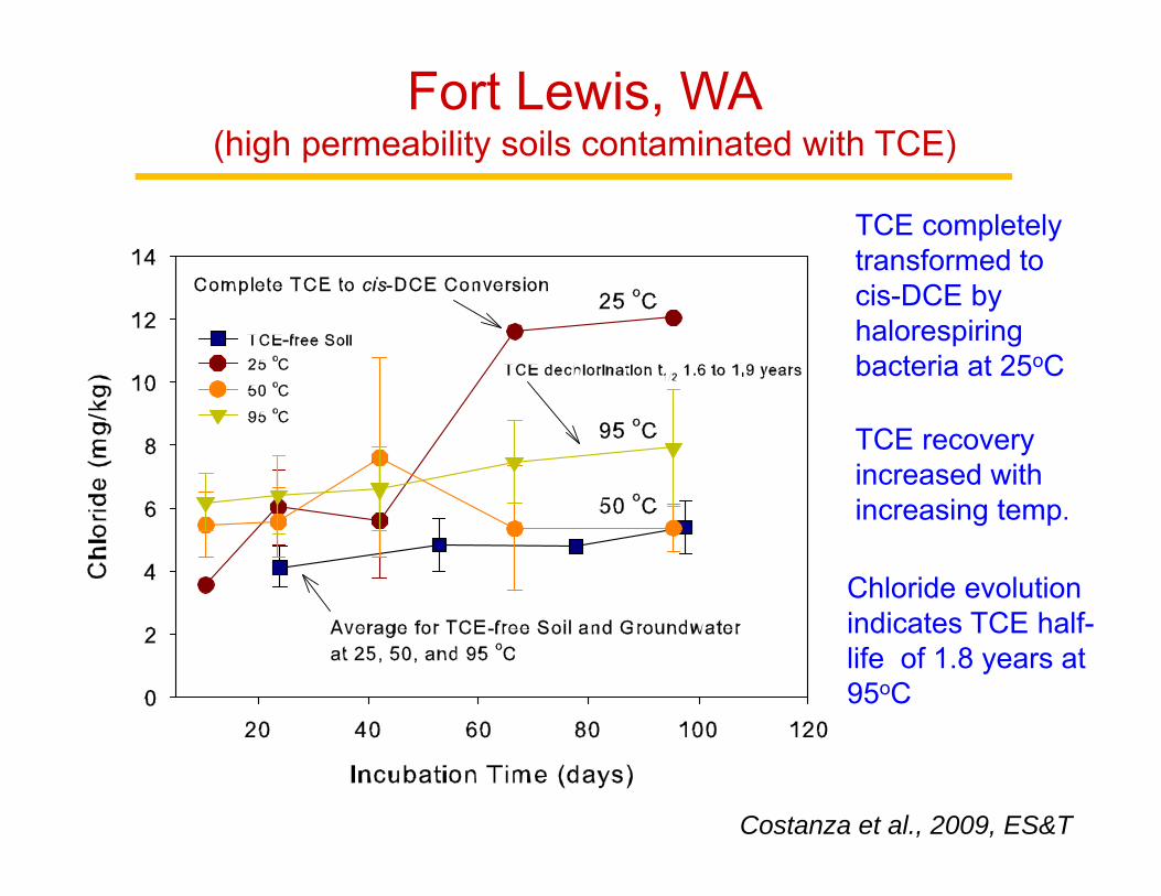
Fort Lewis, WA(high permeability soils contaminated with TCE)
TCE completely transformed to cis-DCE by halorespiringbacteria at 25oC
TCE recovery increased with increasing temp.
Chloride evolution indicates TCE half-life of 1.8 years at 95oC
Costanza et al., 2009, ES&T

Great Lakes, MI(low permeability soil contaminated with PCE)
PCE levels increased 2-3 fold with increasing temperature
Chloride levels were relatively constant at 300 mg/L
Negligible PCE degradation after 185 days at 95oC

Pemaco, CA(medium sand to silt contaminated with TCE)
TCE levels steady over 190 days at temps up to 95oC
Chloride levels constant, no intermediate products detected
Negligible TCE degradation after 190 days at 95oC

Field Site 25oC 50oC 70oC 95oC
Camelot PCE (parent) CO2
CO2 TCE
CO2TCE
CO2, CO, c/tDCE, TCE, 1-butene, benzene, furan
Fort Lewis TCE (parent)
cis-DCE (parent)CO2 CH4
CO2 , CO, CH4, acetylene, ethene, ethane
NACO2, CO, CH4,
acetylene, ethene, ethane
Great Lakes PCE (parent)TCE (parent)
cis-DCE (parent)
CO2, TCA CO2 CO2
CO2, CO, CH4, acetylene,
ethene, ethane, 1-butene
PemacoTCE (parent) CO, CO2 CO, CO2 CO, CO2
CO, CO2, 1-butene, furan
Formation of Reaction Products
Reaction Products ≠ Parent Reactivity Soil Degradation

PV vs Cleff
Volume Water Through Column (L)0 5 10 15 20
Gas
Pha
se (%
)
0
5
10
15
20
25
30
Sour
ce Z
one
Tem
pera
ture
(o C)
20
40
60
80
100
120
H2
CO2
• Great Lakes soil treated with ERH Heated to 74 oC,
• PCE increased from below the 0.2 mg/L detection limit to 106 ± 16 mg/L after heating
• Gas phase samples measured hydrogen, carbon monoxide and carbon dioxide
• Slight increases in gas production following heating from 88 to 100oC and from 88 to 95oC
• Potential for ED formation to support reductive dechlorination
Thermal Treatment (ERH) + Bioremediation(PCE-contaminated Great Lakes Soil)

42% increase in total PCE mass recovery compared to ERH alone (after 20 L of water)
CO2 and Cl increased after each persulfate injection; 4.8% of PCE recovered from column was oxidized
Increase in PCE Mass Recovered Cumulative PCE Mass RecoveredWater Through Column (L)
0 2 4 6 8 10 12 14 16 18 20 22 24
PC
E (m
g)
0
100
200
300
400
500
600
InitiateHeating
7 g/L persulfateERH + Persulfate
ERH
313 mg
447 mg
Water Through Column (L)0 2 4 6 8 10 12 14 16 18 20 22
Incr
ease
in M
ass
(%)
0
10
20
30
40
50
607 g/L persulfate
InitiateHeating Increase from heating
Thermal Treatment (ERH) + Persulfate(PCE-contaminated Great Lakes Soil)
Costanza et al., 2010, ES&T

Microbial Reductive DechlorinationMultiple species dechlorinate PCE and TCE to cis-DCE, but only
Dehalococcoides can transform cis-DCE and VC to ethene
0.2 µmDehalococcoidessp. strain BAV1
Dehalococcoides sp. strain H10, strain VS, strain KB-1/VC
He et al. 2003. Nature. 424:62
Geobacter sp. strain SZ
Sulfurospirillum, Desulfitobacterium,Dehalobacter, Enterobacter, Clostridium, Desulfuromonas
0.2 µm
PCE TCE cis-DCE VC ETH0.2 µm

Microbial Reductive Dechlorination at 30oC
0
3
6
9
12
15
18C
once
ntra
tion
(μm
ole/
bottl
e)
Incubation Time (Days)
PCE
TCEcDCE
VC
Ethene
BDI-30ºC
Complete dechlorination of PCE to Ethene at 30ºC
PCE to cis-DCE pure cultures: Desulfuromonas michiganensis strain BB1 and Geobacter lovleyi strain SZ
PCE to Ethene mixed cultures: Bio-Dechlor INOCULUM™ (BDI) and OW (Rice)

Reductive Dechlorination at 35oC and 40oC
0
3
6
9
12
15
18
0 10 20 30 40
0
3
6
9
12
15
18
0 20 40 60 80
PCETCEDCEVCEthene
Incubation Time (Days)Incubation Time (Days)
Con
cent
ratio
n (μ
mol
e/bo
ttle)
BDI-35ºC BDI-40ºC
Persistence of PCE and Accumulation of Vinyl Chloride at 40ºCAccumulation of Vinyl Chloride at 35ºC
Fletcher et al., 2011, ES&T

CultureTemperature (Degrees C)
24 30 35 40 45
Pure Cultures
SZ cis-DCE cis-DCE cis-DCE cis-DCE ND
BB1 cis-DCE cis-DCE cis-DCE ND ND
Mixed Cultures
BDI Ethene Ethene VC ND ND
OW Ethene Ethene VC VC ND
ND = No Dechlorination= Dechlorination ceased after 1 month
Summary of Pure and Mixed Culture Response to Elevated Temperature

Concluding Thoughts
Abiotic TCE and PCE degradation is generally slow at temperatures less than 120oC, but can be greatly improved in the presence of catalysts (e.g., Fe-containing minerals) and at higher temps (200-400oC).
Microbial reductive dechlorination ceases at temperatures above 40oC, but can be recovered with bioaugmentation and biostimulation, and thermal treatment can release/produce ED.
Substantial sorbed-phase contaminant mass may persist in fine-textured soils even after thermal treatment, but oxidants can enhance rates of contaminant recovery and reactivity.

Project ER-1419 Project ER-2129
Acknowledgements
Kelly Fletcher (Georgia Tech)
Jed Costanza(U.S. EPA)
Graduate Student Fellowship
Frank Löffler(Tennessee)
Ground Water and Ecosystems RestorationR-82947401-0
Natalie Capiro(Tufts)
Tyler Marcet(Tufts)