thermal performance and reliability of bonded interfaces · – synthesis of various joints between...
TRANSCRIPT

NREL is a national laboratory of the U.S. Department of Energy, Office of Energy Efficiency and Renewable Energy, operated by the Alliance for Sustainable Energy, LLC.
Thermal Performance and Reliability of Bonded Interfaces
This presentation does not contain any proprietary, confidential or otherwise restricted information
2011 DOE Vehicle Technologies Program
Review
PI: Sreekant Narumanchi
May 10, 2011
Project ID: APE028

National Renewable Energy Laboratory Innovation for Our Energy Future2
Overview
• Project start date: FY10• Project end date: FY12• Percent complete: 50%
Timeline Barriers Addressed• Cost• Weight• Performance and Lifetime
Targets Addressed• Cost• Specific Power• Power Density
• Total project funding– DOE share: $1M
• FY10 Funding: $400K• FY11 Funding: $600K
Budget• Interactions & Collaborations
- General Motors, Delphi, Btech®, Virginia Tech, University of Maryland, Oak Ridge National Laboratory (ORNL), National Institute of Standards and Technology (NIST), Advanced Engineering Solutions (AES)
• Project lead: NREL
Partners

National Renewable Energy Laboratory Innovation for Our Energy Future3
Relevance/Objectives (1/2)• Excessive temperature (>150°C
for Si devices) can degrade the performance, life and reliability of power electronics components.
• Interfaces in the package can pose a major bottleneck to heat removal.
• Conventional thermal interface materials (TIMs) do not meet thermal performance and reliability targets – industry trend is towards bonded interface materials (BIMs).
• Bonded interfaces, such as solder, degrade at higher temperatures, and are prone to thermomechanical failure under large temperature cycling.
Courtesy: G.Q. Lu, Virginia Tech
BIM 2
Silicon dieDirect-bond-copper (DBC) or Direct-bond-aluminum (DBA)
Copper or aluminum baseplate/coldplate
BIM 1
100
110
120
130
140
150
160
0 2 4 6 8 10 12
Distance across the package (mm)
Tem
pera
ture
(0 C)
100 mm2K/W20 mm2K/W10 mm2K/W5 mm2K/W

National Renewable Energy Laboratory Innovation for Our Energy Future4
Relevance/Objectives (2/2)
• Overall Objective– Investigate thermal performance and reliability of novel bonded
interface materials (such as sintered silver, thermoplastics with embedded carbon fibers) for power electronics applications to meet the following specific objectives
o Thermal resistance of 5 mm2K/W.o Maintain thermal resistance of 5 mm2K/W after 2,000 thermal
cycles from -40 to 150°C.
• Addresses Targets– High-performance, reliable, low-cost bonded interfaces enable
compact, light-weight, low-cost packaging.– Also enables high-temperature coolant and/or air cooling.
• Uniqueness and Impacts– Thermal performance and reliability of novel sintered materials and
thermoplastics in large-area attach will be characterized.
National Renewable Energy Laboratory Innovation for Our Energy Future5
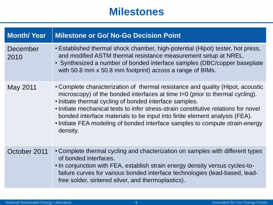
Milestones
Month/ Year Milestone or Go/ No-Go Decision Point
December 2010
•Established thermal shock chamber, high-potential (Hipot) tester, hot press, and modified ASTM thermal resistance measurement setup at NREL.• Synthesized a number of bonded interface samples (DBC/copper baseplate with 50.8 mm x 50.8 mm footprint) across a range of BIMs.
May 2011 •Complete characterization of thermal resistance and quality (Hipot, acoustic microscopy) of the bonded interfaces at time t=0 (prior to thermal cycling).• Initiate thermal cycling of bonded interface samples.• Initiate mechanical tests to infer stress-strain constitutive relations for novel bonded interface materials to be input into finite element analysis (FEA).• Initiate FEA modeling of bonded interface samples to compute strain-energy density.
October 2011 •Complete thermal cycling and chacterization on samples with different types of bonded interfaces.• In conjunction with FEA, establish strain energy density versus cycles-to-failure curves for various bonded interface technologies (lead-based, lead-free solder, sintered silver, and thermoplastics).
National Renewable Energy Laboratory Innovation for Our Energy Future6
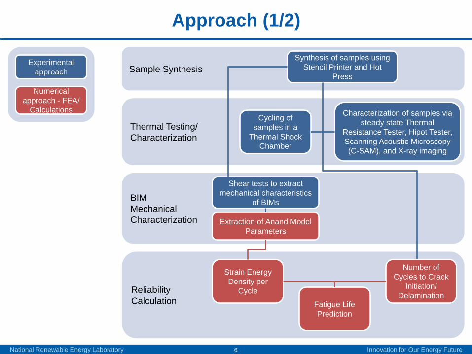
Approach (1/2)
Sample Synthesis
BIMMechanical Characterization
ReliabilityCalculation
Thermal Testing/Characterization
Synthesis of samples using Stencil Printer and Hot
Press
Cycling of samples in a
Thermal Shock Chamber
Characterization of samples via steady state Thermal
Resistance Tester, Hipot Tester, Scanning Acoustic Microscopy (C-SAM), and X-ray imaging
Shear tests to extractmechanical characteristics
of BIMs
Number of Cycles to Crack
Initiation/Delamination
Fatigue Life Prediction
Strain Energy Density per
Cycle
Extraction of Anand Model Parameters
Experimental approach
Numerical approach - FEA/
Calculations

NATIONAL RENEWABLE ENERGY LABORATORY DOE APEEM FY11 Kickoff Meeting
Approach (2/2)

National Renewable Energy Laboratory Innovation for Our Energy Future8
Accomplishments – Acquisition of DBC, Baseplate, BIMs
Bond Material Type
Name Comments
Solder Sn63Pb37 Baseline (lead-based solder)
Solder Henkel Innolot LF318 Lead-free solder
Solder SAC305 Lead-free solder
Sintered silver NanoTach Based on nanoscale silver particles
Sintered silver Heraeus C8829A Based on micron-size silver particles
Sintered paste Silver-Indium Based on micron-size particles
Adhesive Dow Corning DA-6534 Silver-filled, heat-curable silicone adhesive
Adhesive Btech HM-2 Thermoplastic (polyamide) film with embedded carbon fibers
Adhesive Henkel Hysol® CF3350 Thermally conductive silver-filled film
• Acquired silver sintered materials, silver-based adhesives, thermoplastics with embedded carbon fibers, and solders (both lead-based and lead-free as baseline)
- Interface between 50.8 mm x 50.8 mm footprint DBC/copper baseplate assembly (DBC based on aluminum nitride (AlN) substrate).
DBC/baseplate assembly
Credit: Doug DeVoto, NREL

National Renewable Energy Laboratory Innovation for Our Energy Future9
Accomplishments – Bonded Interface Synthesis and Imaging
• Five samples of each BIM (between DBC/copper baseplate) were synthesized for testing- Silver coating on DBC and baseplate.
• Samples followed manufacturer-specified reflow profiles, and bonds were inspected for quality.
• X-ray imaging indicated some voiding in Sn-Ag-Cu (SAC) solder samples.
Screw Jack
Cold Plates
Hot Plates
Hot Press
SAC solder (middle) SAC solder (edge) Pb-Sn solder (edge)Pb-Sn solder (middle)Courtesy: Jesus Calata, Virginia Tech
Credit: Doug DeVoto, NREL

National Renewable Energy Laboratory Innovation for Our Energy Future10
Accomplishments – Modified ASTM Setup for Thermal Resistance Testing
• New blocks fabricated to enable thermal resistance measurement on 50.8 mm X 50.8 mm footprint samples.
• ASTM results for new blocks (50.8 mm x 50.8 mm) can be directly compared to results from previous blocks (31.8 mm diameter).
• Similar thermal resistance results for Dow TC-5022 grease obtained from both block configurations –gives confidence in the use of new blocks (50.8 mm x 50.8 mm).
ASTM Stand
Credit: Doug DeVoto, NREL
0
20
40
60
80
0 100 200 300Ther
mal
Res
ista
nce
(mm
2 K/W
)
Grease Thickness (µm)
Thermal Resistance Variation by Meter Block Geometry
31.8 mm Round
50.8 mm Square
National Renewable Energy Laboratory Innovation for Our Energy Future11
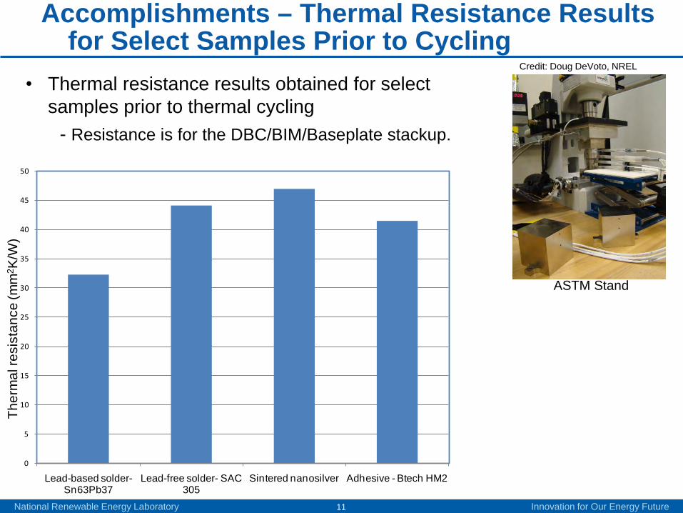
Accomplishments – Thermal Resistance Results for Select Samples Prior to Cycling
ASTM Stand
Credit: Doug DeVoto, NREL
0
5
10
15
20
25
30
35
40
45
50
Lead-based solder-Sn63Pb37
Lead-free solder- SAC 305
Sintered nanosilver Adhesive - Btech HM2
Ther
mal
resi
stan
ce (m
m2 K
/W)
• Thermal resistance results obtained for select samples prior to thermal cycling
- Resistance is for the DBC/BIM/Baseplate stackup.
National Renewable Energy Laboratory Innovation for Our Energy Future12
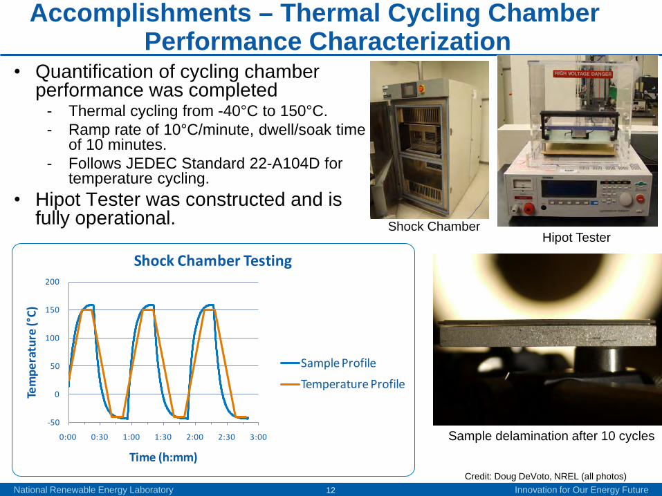
Accomplishments – Thermal Cycling Chamber Performance Characterization
• Quantification of cycling chamber performance was completed
- Thermal cycling from -40°C to 150°C.- Ramp rate of 10°C/minute, dwell/soak time
of 10 minutes.- Follows JEDEC Standard 22-A104D for
temperature cycling.• Hipot Tester was constructed and is
fully operational. Shock ChamberHipot Tester
Credit: Doug DeVoto, NREL (all photos)
-50
0
50
100
150
200
0:00 0:30 1:00 1:30 2:00 2:30 3:00
Tem
pera
ture
(°C)
Time (h:mm)
Shock Chamber Testing
Sample Profile
Temperature Profile
Sample delamination after 10 cycles
National Renewable Energy Laboratory Innovation for Our Energy Future13
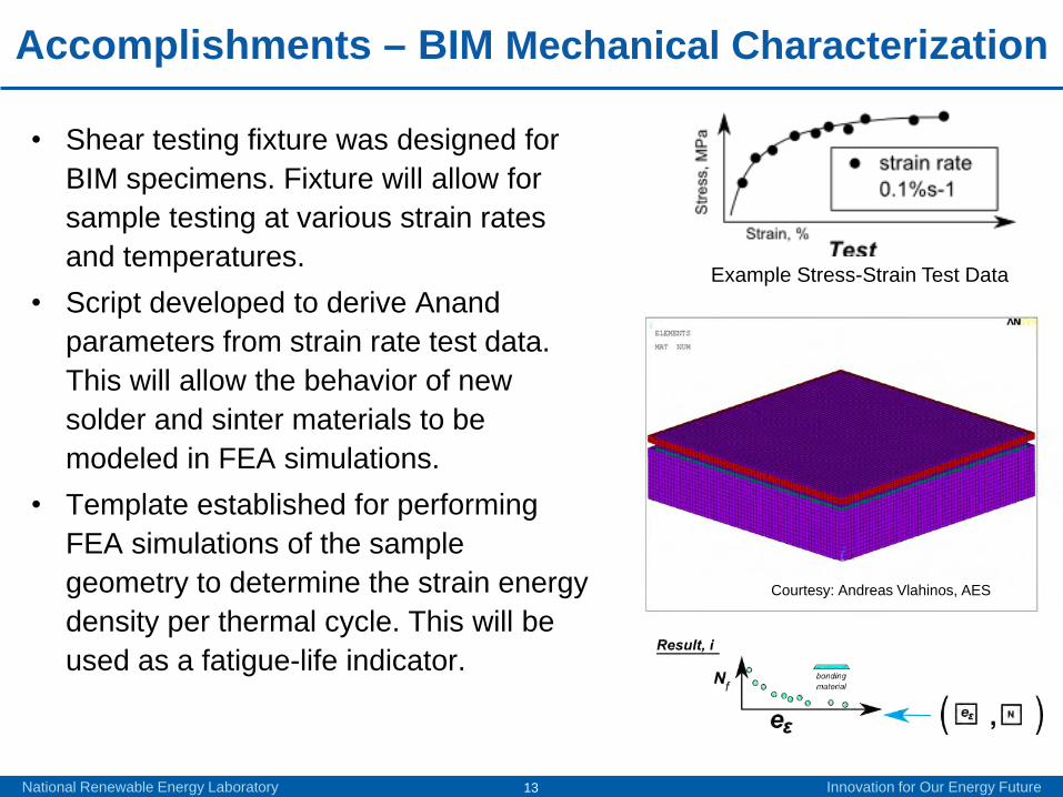
Accomplishments – BIM Mechanical Characterization
• Shear testing fixture was designed for BIM specimens. Fixture will allow for sample testing at various strain rates and temperatures.
• Script developed to derive Anand parameters from strain rate test data. This will allow the behavior of new solder and sinter materials to be modeled in FEA simulations.
• Template established for performing FEA simulations of the sample geometry to determine the strain energy density per thermal cycle. This will be used as a fatigue-life indicator.
Example Stress-Strain Test Data
Courtesy: Andreas Vlahinos, AES
National Renewable Energy Laboratory Innovation for Our Energy Future14
0 50 100 150 200 250 300
-40
-20
0
20
40
60
80
100
120
140
Time (min)
Tem
pera
ture
(C)
Temperature Cycling
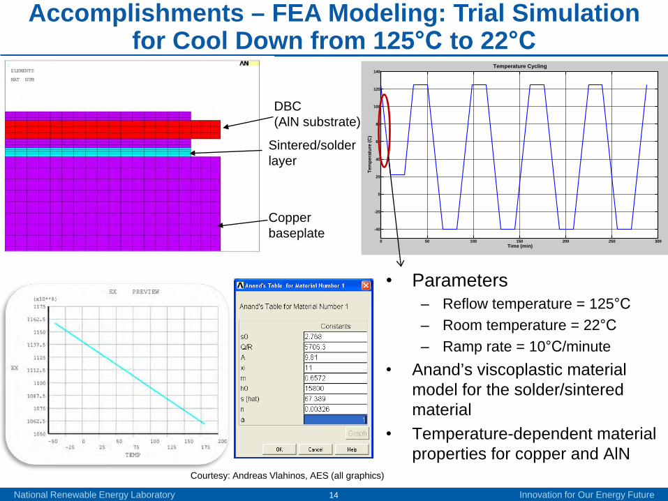
• Parameters– Reflow temperature = 125°C– Room temperature = 22°C– Ramp rate = 10°C/minute
• Anand’s viscoplastic material model for the solder/sintered material
• Temperature-dependent material properties for copper and AlN
Accomplishments – FEA Modeling: Trial Simulation for Cool Down from 125°C to 22°C
Courtesy: Andreas Vlahinos, AES (all graphics)
DBC (AlN substrate)
Copper baseplate
Sintered/solder layer

National Renewable Energy Laboratory Innovation for Our Energy Future15
Upper/top layer of bonded joint
Accomplishments – FEA Modeling: Stress Distribution (Cool Down from 125°C to 22°C)
• Equivalent stress distribution in the upper/top and middle layer of the bonded joint.
• Stresses are higher in the layer adjoining the DBC and higher in the corner regions.Courtesy: Andreas Vlahinos, AES (all graphics)
Middle layer of bonded joint
National Renewable Energy Laboratory Innovation for Our Energy Future16
Quarter Symmetry
Model
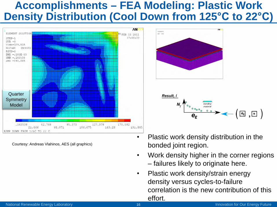
Accomplishments – FEA Modeling: Plastic Work Density Distribution (Cool Down from 125°C to 22°C)
• Plastic work density distribution in the bonded joint region.
• Work density higher in the corner regions – failures likely to originate here.
• Plastic work density/strain energy density versus cycles-to-failure correlation is the new contribution of this effort.
Courtesy: Andreas Vlahinos, AES (all graphics)
National Renewable Energy Laboratory Innovation for Our Energy Future17
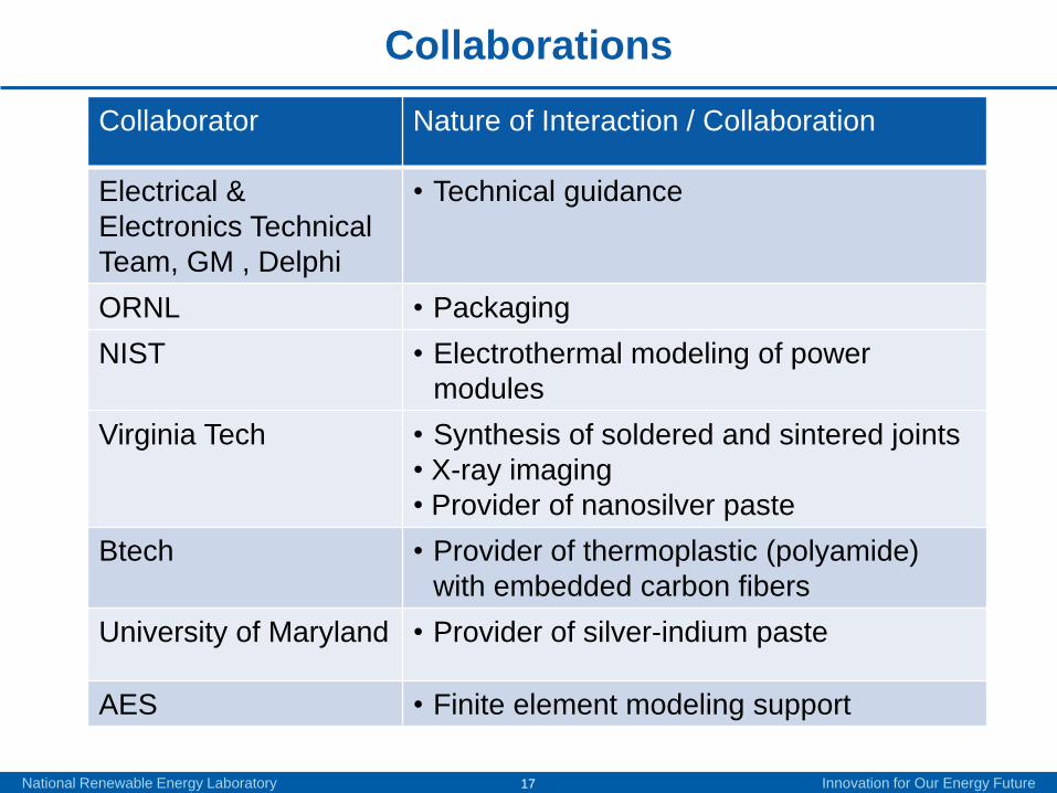
Collaborations
Collaborator Nature of Interaction / Collaboration
Electrical & Electronics Technical Team, GM , Delphi
• Technical guidance
ORNL • PackagingNIST • Electrothermal modeling of power
modules Virginia Tech • Synthesis of soldered and sintered joints
• X-ray imaging• Provider of nanosilver paste
Btech • Provider of thermoplastic (polyamide) with embedded carbon fibers
University of Maryland • Provider of silver-indium paste
AES • Finite element modeling support
National Renewable Energy Laboratory Innovation for Our Energy Future18
• Remainder of FY11– Perform thermal resistance test and quality
characterization (C-SAM, X-ray, Hipot) on bonded samples prior to cycling.
– Perform mechanical tests to characterize stress-strain constitutive relationship (to go into FEA modeling).
– Perform thermal cycling on bonded samples.– Perform periodic (after 100 cycles) thermal resistance
and quality characterization.– Perform FEA modeling to compute strain energy density
for DBC/baseplate bonded configuration (for different bonded materials).
– Key output will be strain energy density versus cycles-to-failure for different BIM technologies.
Future Work (1/2)
National Renewable Energy Laboratory Innovation for Our Energy Future19
Future Work (2/2)
• FY12– Perform synthesis, characterization and modeling of
thermal performance and reliability of a select few bonded interfaces between DBA/aluminum baseplate.
– Study impact of different coatings on substrate and/or baseplate.
National Renewable Energy Laboratory Innovation for Our Energy Future20
Summary (1/2)
• DOE Mission Support– BIMs are a key enabling technology for compact, light-weight, low-cost,
reliable packaging and for high-temperature coolant and air-cooling technical pathways.
• Approach– Synthesis of various joints between DBA/DBC and baseplate (Cu/Al),
thermal shock/temperature cycling, thermal resistance measurements, high-potential test and joint inspection (X-ray, C-SAM), and strain energy density versus cycles-to-failure models.
• Accomplishments– Synthesized a number of bonded interfaces between DBC/copper
baseplate based on different BIM technologieso Lead-based and lead-free solder, sintered silver (micron-size and
nanosilver), thermoplastic, silver adhesive/epoxy.– Initiated FEA for bonded interface geometries.– Initiated thermal resistance measurement and quality characterization for
the different bonded interfaces prior to thermal shock/cycling.
National Renewable Energy Laboratory Innovation for Our Energy Future21
Summary (2/2)• Future Work
– For bonded interface between DBC/copper baseplate:o Perform thermal cycling of bonded samples.o Characterize thermal resistance and quality of bond.o Characterize BIM to obtain stress-versus-strain mechanical constitutive relationships.o Perform FEA modeling to infer strain energy density.o Correlate strain energy density to cycles-to-failure.
– Investigate thermal performance and reliability of bonded interfaces between DBA/aluminum – work plan similar to that for bonded interfaces between DBC/copper baseplate.
– Investigate impact of coatings on thermal performance and reliability.
• Collaborations– Electrical & Electronics Technical Team, GM, Delphi– ORNL– NIST– Virginia Tech – Btech– University of Maryland – AES
NREL is a national laboratory of the U.S. Department of Energy, Office of Energy Efficiency and Renewable Energy, operated by the Alliance for Sustainable Energy, LLC.
For more information contact:
Principal InvestigatorSreekant [email protected]: (303)-275-4062
APEEM Task LeaderF. Patrick [email protected]: (303)-275-3653
Acknowledgements:
Susan Rogers, U.S. Department of Energy
Team Members:
Doug DeVotoMark MihalicPatrick McCluskey