thermal overload protection of power transformers...
TRANSCRIPT

Thermal Overload Protection of Power Transformers – Operating Theory and Practical Experience
Rich Hunt, M.S., P.E. Senior Field Application Engineer
NxtPhase T&D Corporation.
Michael L. Giordano B.S., P.E. Electrical Engineer
Distribution Engineering & Design Northeast Utilities Systems
Presented at the
59th Annual Protective Relaying Conference Georgia Tech
Atlanta, Georgia April 27th – 29th, 2005

Thermal Overload Protection of Power Transformers – Operating Theory and Practical Experience 2005 Georgia Tech Protective Relaying Conference
1
Thermal Overload Protection of Power Transformers – Operating Theory and Practical Experience
Rich Hunt, M.S., P.E.
Senior Field Application Engineer NxtPhase T&D Corporation.
Michael L. Giordano B.S., P.E. Electrical Engineer
Distribution Engineering & Design Northeast Utilities Systems
Introduction
TRADITIONAL methods of protecting power transformers use functions based on measured current and voltage. These functions are useful in detecting short circuits and other transient electrical fault events in the transformer. However, for liquid-immersed power transformers, the temperature of the winding hot-spot is the important factor in the long-term life of the transformer. The insulating oil temperature is dependent on the winding temperature, and is used to indicate the operating conditions of the transformer. Many numerical transformer protection relays available today include protection functions that operate on insulating oil temperatures, calculated loss-of-life due to high oil temperature, and predicted oil temperatures due to load. These types of functions are not routinely applied, often since protection engineers may lack an understanding of the operating principles of these functions, and transformer operating conditions, to properly determine a settings methodology. A factor to consider when looking at these temperature-based functions is the risk of accelerated aging, and transformer failure, is increasing. Modern utility operating practices try to maximize the utilization of power transformers, which may increase the occurrence of over-temperature conditions, and transformer aging. Over-temperature conditions and accelerated aging are adverse system events that must be identified and protected against.
The most common function provided for thermal protection of power transformers is the thermal overload (ANSI 49) function. To properly set this function, the protection engineer must understand the basics of the thermal performance of power transformers, and the basic design of the specific implementation of the 49 function.
Northeast Utilities has implemented thermal protection of substation power transformers. The temperature protection is combined with distribution automation to manage transformer load. Thermal overload levels of the transformers force an automatic load transfer through feeder circuit re-configuration. Predictive overload alarms warn the Distribution System Operators of the pending automatic forced load transfer, to allow manual intervention. The settings criteria, control logic, and operations criteria for the thermal overload protection are discussed, as well as an overview of the operating experience.

Thermal Overload Protection of Power Transformers – Operating Theory and Practical Experience 2005 Georgia Tech Protective Relaying Conference
2
Pump(optional)
RADIATORMAIN TANKInsulating Oil
WindingsPaper Insulation
Basics of Transformers Thermal Performance
THIS paper considers only the performance and protection of liquid-immersed power transformers. Power transformers are transformers used between the generating stations and distribution network, and are larger than 500 kVA in size. Power transformers use a laminated steel core with copper or aluminum windings. The windings have a solid insulation of refined paper, and highly refined mineral oil is the insulating and cooling medium for the entire transformer. The core, windings, and insulation all have specific thermal capabilities. Losses in the winding and core cause temperature rises in the transformer, which are transferred to the insulating oil. Failure to limit these temperature rises to the thermal capability of the insulation and core materials can cause premature failure of the transformer.
Figure 1: Simple transformer representation
A transformer is rated at the power output the transformer can continuously deliver at rated voltage and frequency, without exceeding the specified temperature rise. This temperature rise is based, in part, on the thermal limitations of the core, winding, and insulation. Therefore, the MVA rating of the transformer is based on the maximum allowable temperature of the insulation. Design standards express temperature limits for transformers in rise above ambient temperature. The use of ambient temperature as a base ensures a transformer has adequate thermal capacity, independent of daily environmental conditions.

Thermal Overload Protection of Power Transformers – Operating Theory and Practical Experience 2005 Georgia Tech Protective Relaying Conference
3
Transformer Heating No-load losses and load losses are the two significant sources of heating considered in thermal modeling of power transformers. No-load losses are made up of hysteresis and eddy loss in the transformer core, and these losses are present whenever the transformer is energized. Hysteresis loss is due to the elementary magnets in the material aligning with the alternating magnetic field. Eddy currents are induced in the core by the alternating magnetic field. The amount of hysteresis and eddy loss is dependent on the exciting voltage of the transformer.
Load losses are the more significant source of transformer heating, consisting of copper loss due to the winding resistance and stray load loss due to eddy currents in other structural parts of the transformer. The copper loss consists of both DC resistance loss, and winding eddy current loss. The amount of loss is dependent on transformer load current, as well as oil temperature. DC resistance loss increases with increasing temperature, while other load losses decrease with increasing oil temperature. All of these factors are considered in calculations of thermal transformer performance.
The basic method for cooling transformers is transferring heat from the core and windings to the insulating oil. Natural circulation of the oil transfers the heat to external radiators. The radiators increase the cooling surface area of the transformer tank. Pumps may be used to increase the flow of oil, increasing the efficiency of the radiators. In non-directed flow transformers, the pumped oil flows freely through the tank. In directed flow transformers, the pumped oil is forced to flow through the windings. Forced air cooling is commonly applied on large power transformers, using fans to blow air over the surface of the radiators, which can double the efficiency of the radiators. For some large power transformers, water cooling may replace large radiators. Large power transformers may also have additional ratings for multiple stages of forced cooling. Normally, only two stages are applied, providing transformer ratings equivalent to 133% and 167% of the self-cooled rating.
Both the IEEE and the IEC established standard designations for the various cooling modes of transformers. The IEEE has adopted the IEC designations. The designation completely describes the cooling method for the transformer, and the cooling method impacts the response of the transformer insulating oil to overload conditions. Table 1 lists the common transformer cooling designations.
Table 1: Transformer cooling designations
Old IEEE Cooling Designations IEC Equivalent Self-cooled OA ONAN Forced air cooled FA ONAF Directed-flow forced liquid cooled FOA ODAF Water cooled OW OFWF Forced liquid and water cooled FOW OFWF
Impact of Oil Temperature on Power Transformers INCREASING transformer load increases the temperature of the insulating oil, so loading above the nameplate rating involves some risk. Transformers are rated at a maximum oil temperature rise over ambient, with modern transformers rated at 65º C rise above ambient. These risks include reduced dielectric integrity due to gassing, reduced mechanical strength and permanent deformation of structural components such as the core and windings, or possible damage to

Thermal Overload Protection of Power Transformers – Operating Theory and Practical Experience 2005 Georgia Tech Protective Relaying Conference
4
auxiliary equipment such as tap changers, bushings, or current transformers. Oil temperature, therefore, makes a good choice to use as the basis of a protection function, providing sensitivity to a number of possible transformer issues. Standard temperature limits are defined in the IEEE Guide for Loading Mineral-Oil Immersed Power Transformers, (described in the rest of this paper as the Guide for Loading) are listed in Table 2.
Table 2: Standard temperature limits, 65º C rise transformer, 30º ambient temperature
Standard temperature limits
Average winding temperature rise 65º C Above ambient Hot-spot temperature rise 80º C Above ambient Top liquid temperature rise 65º C Above ambient Maximum temperature limit 110º C Absolute
One factor in transformer over-temperature conditions is the loss of insulation life. Aging of the refined paper insulation is based on temperature, moisture content, and oxygen content over time. Modern oil preservation systems minimize the impact of moisture and oxygen on insulation life. Therefore, aging studies of transformers use the hottest-spot oil temperature to determine transformer life. [3]
The term “transformer life” is assumed to mean the insulation life of the transformer, not the total operational life. “Loss-of-life” is assumed to mean loss of the total insulation life of the transformer. For 65º C rise transformer operate at the maximum temperature, the Guide for Loading uses 65,000 hours (7.4 years) as normal life expectancy, based on 50% retained mechanical strength of the insulation. The Guide for Loading also states that 180,000 hours (20.6 years) is also a reasonable value for a normal life expectancy. This means, practically, that the transformer can be operated at full load for 65,000 hours over the total operational life of the transformer before the mechanical strength of the insulation is reduced by half, increasing the likelihood of failure during short circuits. The relationship between oil temperature and transformer life expectancy is given by the accelerating aging factor, FAA. FAA for 65º C rise transformers is defined as:
+Θ−
= 273000,15
383000,15
HeFAA per unit, [1] Where ΘH is the hottest-spot temperature (ºC) The FAA is a multiplier for the rate of transformer aging, and is greater than 1 when the
hottest-spot temperature exceeds the 30º C ambient design temperature limit of 110º C. This factor adjusts the normal life expectancy of the transformer for over-temperatures. For a transformer operated continuously at a specific temperature, the actual life expectancy is the normal life expectancy divided by the accelerating aging factor FAA.

Thermal Overload Protection of Power Transformers – Operating Theory and Practical Experience 2005 Georgia Tech Protective Relaying Conference
5
For example, if ΘH = 140º C, then
hoursexpectancyLife
eeF HAA
37792.17
000,652.17273140
000,15383
000,15273
000,15383
000,15
==
===
+
−
+Θ−
Transformers will not be operated at a constant over-temperature for a long period of time. Therefore, it is more practical to define a loss-of-life factor that is representative of the amount of insulation strength lost during an over-temperature event. The Guide for Loading defines this loss-of-life factor as:
∑
∑
=
=
∆
∆
=N
nn
N
nnAA
EQA
t
tnF
F
1
1
,
Reference [1]
Where FAA is the accelerating aging factor n is the step for a specific accelerating aging factor calculation ∆tn is the time interval for the calculation step N is the total number of steps.
Comparing this discrete loss-of-life to the total life expectancy provides a calculation for a percentage of loss-of-life. In short, this method consists of calculating the loss-of-life at regular time intervals, and determining an average loss-of-life across the entire event.
LOLFEQA %100
000,65=× or lifeainingRem
FEQA =×−
100000,65
000,65
It is easy to see from these equations that increasing operating temperatures rapidly decrease the life expectancy of the transformer. For example, consider a 6 hour over-temperature event where the hot-spot temperature for each hour is as shown in the table.
Table 3: Example transformer temperatures for loss-of-life calculation
Hour Hot-spot (º C) FAA 1 110 0.350 2 125 1.000 3 145 26.56 4 135 11.02 5 118 2.228 6 110 1.000
So, ∆tn = 1 hour, and N = 6 hours

Thermal Overload Protection of Power Transformers – Operating Theory and Practical Experience 2005 Georgia Tech Protective Relaying Conference
6
hoursperF
FFFFFFF
EQA
AAAAAAAAAAAAEQA
6697.7618.46
6000.1228.202.1156.26000.1350.0
111111654321
==
+++++=
++++++++++
=
lifertransformeofhrs
hrsFLOL EQA %071.0100
000,65
6% =×
×=
Power Transformer Operating Temperatures WHEN monitoring the thermal performance of transformers for protection purposes, using the right temperature measurement is important. There are two useful temperature measurements.
Top-oil temperature is the temperature of the insulating oil as measured at the top of the transformer tank. The top-oil temperature increases approximately with the square of the current. Per IEEE standards, the rated top-oil temperature rise is 65º C above ambient. The Guide for Loading gives the top-oil temperature as
TOATO ∆Θ+Θ=Θ Where ΘTO is the top-oil temperature (ºC) ΘA is the ambient temperature (ºC) ∆ΘTO is the top-oil rise over ambient temperature (ºC)
Top-oil temperature rise is directly related to load current, and the thermal characteristics of the transformer. The Guide for Loading defines the top-oil rise over ambient temperature for a step load change as
( ) iTOiTOUTOTO TO ,
1
,, exp1 ∆Θ+
−∆Θ−∆Θ=∆Θ τ
Where ∆ΘTO is the top-oil rise over ambient temperature (ºC) ∆ΘTO,U is the ultimate top-oil rise over ambient for load L (ºC) ∆ΘTO,i is the initial top-oil rise over ambient for t = 0 (ºC) τTO is the top-oil time constant of the transformer (hours)
The initial top-oil rise is a factor of the load current, and is further defined by the Guide for Loading as:
( )( )
ni
RTOiTO RRK
++
∆Θ=∆Θ1
12,,
Where ∆ΘTO,i is the initial top-oil rise over ambient for t = 0 (ºC) ∆ΘTO,R is the top-oil rise over ambient temperature at rated load (ºC) K is the ratio of load L to rated load (per unit)
n is an empirically derived exponent used to calculate the variation of ∆ΘTO with changes in load, and is selected based on the transformer cooling mode.

Thermal Overload Protection of Power Transformers – Operating Theory and Practical Experience 2005 Georgia Tech Protective Relaying Conference
7
These equations show the relationship between ambient temperature, transformer loading, and top-oil temperature.
HOT-SPOT temperature is the hottest temperature spot in the transformer winding. The location of the winding hottest spot is dependent on the physical design of the transformer. The Guide for Loading specifies a design limit for a normal hot-spot temperature of 110º C, or 80º C over an assumed ambient temperature of 30º C. For emergency overload situations, the Guide for Loading permits hot-spot temperatures exceeding this 110º C limit. However, these excessive temperatures may lead to an unacceptable loss of insulation life.
Hot-spot temperature is dependent on the ambient temperature, and the rise in top-oil temperature, as defined by the Guide for Loading:
HTOAH ∆Θ+∆Θ+Θ=Θ
Where ΘH is the winding hottest-spot temperature (ºC) ΘA is the ambient temperature (ºC) ∆ΘTO is the top-oil rise over ambient temperature (ºC) ∆ΘH is the winding hottest-spot rise over top-oil temperature (ºC)
Just as with top-oil temperature, the winding hot-spot temperature is dependent on transformer loading and transformer thermal characteristics. The transient winding hottest-spot temperature over top-oil temperature is given by:
( ) iHiHUHH w ,
1
,, exp1 ∆Θ+
−∆Θ−∆Θ=∆Θ τ
Where ∆ΘH is the winding hottest-spot rise over top-oil temperature (ºC) ∆ΘH,U is the ultimate winding hottest-spot rise over top-oil for load L (ºC) ∆ΘH,i is the initial winding hottest-spot rise over top-oil for t = 0 (ºC) τw is the winding time constant at the hot-spot location (hours)
The initial hot-spot rise is a factor dependent on load current, and is further defined by the Guide for Loading as:
miRHiH K 2
,, ∆Θ=∆Θ Where ∆ΘH,i is the initial winding hottest-spot rise over top-oil for t = 0 (ºC)
∆ΘH,R is the winding hottest-spot rise over top-oil temperature at rated load (ºC)
K is the ratio of load L to rated load (per unit) m is an empirically derived exponent used to calculate variation of ∆ΘH
with changes in load, and is selected based on the transformer cooling mode.
Just as with the top-oil temperature, the hot-spot temperature is directly dependent on ambient temperature and transformer loading.
The other conclusion to draw from these equations is the dependence of both top-oil and hot-spot temperatures on the ambient temperature. As transformers are rated in rise above ambient,

Thermal Overload Protection of Power Transformers – Operating Theory and Practical Experience 2005 Georgia Tech Protective Relaying Conference
8
the ambient temperature is a key influence on the ultimate temperature rise of the transformer, so the ultimate temperature rise will vary greatly with seasonal conditions.
Transformer Loading States
TOP-OIL and hot-spot temperature conditions, when they exceed the normal design limit of 110º C, increase the aging of a transformer. There are operating circumstances where loading the transformer beyond normal design limits may be necessary. For these circumstances, the Guide for Loading defines 4 transformers operating states. These 4 states are normal life expectancy loading, planned loading beyond nameplate rating, long-term emergency loading, and short-term emergency loading. For each of these conditions, the Guide for Loading provides an acceptable hot spot winding temperature, and a relative loss-of-life factor.
Table 4: Transformer loading states
Normal life expectancy
loading
Planned loading beyond
nameplate rating
Long-term emergency
loading
Short-term emergency
loading
Top-oil temperature 105° C 110° C 110° C 110° C Hot-spot temperature 110° C 130° C 140° C 180° C Loss-of-life factor 1.0000 6.9842 17.1994 424.9218 Resulting life 65,000 hours 9,307 hours 3,779 hours 153 hours
Normal life expectancy loading is the basic loading for a power transformer that results in normal life expectancy, when continuously loaded at rated output, and operated under usual conditions.
Figure 2: Typical temperature profile for normal life expectancy loading
Time (hours)
Hot SpotTemp
110o
120o

Thermal Overload Protection of Power Transformers – Operating Theory and Practical Experience 2005 Georgia Tech Protective Relaying Conference
9
Planned Loading Beyond Nameplate (PLBN) Rating is defined as a planned, repetitive loading above nameplate rating, but not a continuous loading above nameplate. Usually this rating is restricted to transformers that do not carry a continuous steady load.
Figure 3: Typical temperature profile for PLBN
Long-Time Emergency (LTE) Loading is a continuous permissible overload, to account for prolonged outages of a system element, such as a transmission line. It is expected that this type of loading is rare, with only two or three occurrences over the life of the transformer.
Figure 4: Typical temperature profile for LTE
Hot SpotTemp
120o
130o
Time (hours)
110o
Hot SpotTemp
130o
140o
Time (hours)
120o
110o

Thermal Overload Protection of Power Transformers – Operating Theory and Practical Experience 2005 Georgia Tech Protective Relaying Conference
10
Short-Time Emergency (STE) Loading is an unusually heavy loading brought on by a combination of unlikely system events, generally a second or third contingency type event, and loading the transformer to this level for a short period of time is the best alternative for operating the system.
Figure 5: Typical temperature profile for STE
THERMAL overload protection functions should use these transformer loading states, and the resulting loss-of-life factors, as a key component in determining appropriate settings.
Methods to Determine Transformer Operating Temperatures
THERE are three operating temperatures that can be used as the basis for temperature protection of power transformers: the ambient temperature, top-oil temperature, and hot-spot temperature. It is possible to estimate transformer operating temperatures, directly measure the ambient, top-oil, and hot-spot temperatures, or calculate the top-oil and hot-spot temperatures. Understanding how these temperatures are determined by the relay helps determining the appropriate protection application and settings.
Estimating Transformer Operating Temperature ESTIMATING transformer operating temperature uses a thermal replica to estimate heating and cooling of the transformer based on the current measured on one side of the transformer. The thermal replica model calculates a maximum temperature rise based on the measured current, the thermal time constant for the transformer, and the maximum permissible current of the transformer. Thermal replica models have traditionally been implemented using an electro-mechanical thermal replica device. However, this paper discusses only a mathematical thermal replica as implemented in a numerical transformer protection relay.
An example of a thermal replica model is given by the following equation
2
max11
×=Θ×+
ΘI
Idtd
oiloil ττ [8]
Where Θ is the oil temperature. This can be top-oil or hot-spot temperature (ºC) I is the transformer load (amps) Imax is the maximum permissible load current (amps)
τoil is the appropriate oil time constant, either top-oil or hot-spot
Hot SpotTemp
130o
140o
Time (hours)
120o
110o

Thermal Overload Protection of Power Transformers – Operating Theory and Practical Experience 2005 Georgia Tech Protective Relaying Conference
11
MAIN TANK
Pump(optional)
TTTO
RADIATOR
CTLoad
TTHS
TempAmbient
Top-oiltemperature
Hot-spottemperature
Load current
Ambienttemperature
The biggest advantage to using a thermal replica for transformer temperature protection is the ease of implementation. The function involves only settings in the relay, with no need to physically install and connect temperature sensors. However, this method doesn’t account for ambient temperature, and provides only a simple representation of transformer oil temperatures due to load, but is not truly top-oil temperature or hot-spot temperature. Functionally, therefore, this is essentially an overcurrent function, with an asymptotic time delay. Thermal replica based protection elements typically include several threshold settings, to alarm and trip on increasing temperature conditions.
Figure 6: Transformer operating temperatures
Measuring Ambient Temperature TRANSFORMER operating temperatures are based on rise above ambient temperature. Models of transformer oil temperatures generally require directly measuring the ambient temperature to determine the operating state of the transformer. For example, as previously defined, the hot-spot oil temperature is directly dependent on the ambient temperature. So the major advantage of measuring the ambient temperature is improving the accuracy of top-oil temperature calculations, and hot-spot temperature calculations. Measuring the ambient temperature requires connecting a temperature probe to the relay. Temperature probes traditionally use a transducer output, but may use RTD connections in some instances.
Measuring Top-Oil Temperature TOP-OIL temperature is easily measured. Suitable top-oil temperature sensors are installed as part of the transformer cooling system. The actual temperature sensor is usually an RTD mounted in a heated thermowell in one phase of the transformer. Top-oil temperature sensors are also easy to
Thermal Overload Protection of Power Transformers – Operating Theory and Practical Experience 2005 Georgia Tech Protective Relaying Conference
12
retrofit, as sensors that mount externally to the tank are available. Directly measuring the top-oil temperature improves the accuracy of temperature based protection functions, and improves the accuracy of hot-spot temperature calculations.
Use of measured top-oil temperature does require a temperature sensor at the transformer, with a physical connection to the transformer protection relay. With newer transformer installations, the top-oil temperature may be an output of the transformer cooling controls. Measuring the top-oil temperature at only one point assumes some homogeneity among the oil temperature in the transformer tank. It is possible to use multiple sensors for per-phase measurements of top-oil temperature, and therefore per-phase temperature protection of the transformer. However, the top-oil temperature will be identical between all three phases, unless there is significant load imbalance.
Measuring Hot-Spot Temperature IN general, the goal of temperature-based transformer protection is to limit the impact of the hottest-spot temperature on transformer winding insulation. Therefore, using measured hot-spot temperature provides the most accurate protection against transformer over-temperature conditions, and may be the only measurement required for protection purposes. The biggest disadvantage to this method is the hot-spot temperature sensor. Practically, the sensor must be installed during manufacture of the transformer, as the sensor must be physically installed in the transformer winding at a point calculated by the transformer designer to be the location of the hot-spot. As the temperature sensors must also be electrically isolated from the transformer tanks and windings, hot-spot temperature sensors are typically fiber-optic sensors. In practice, it is rare to measure the hot-spot temperature, except for large power transformers.
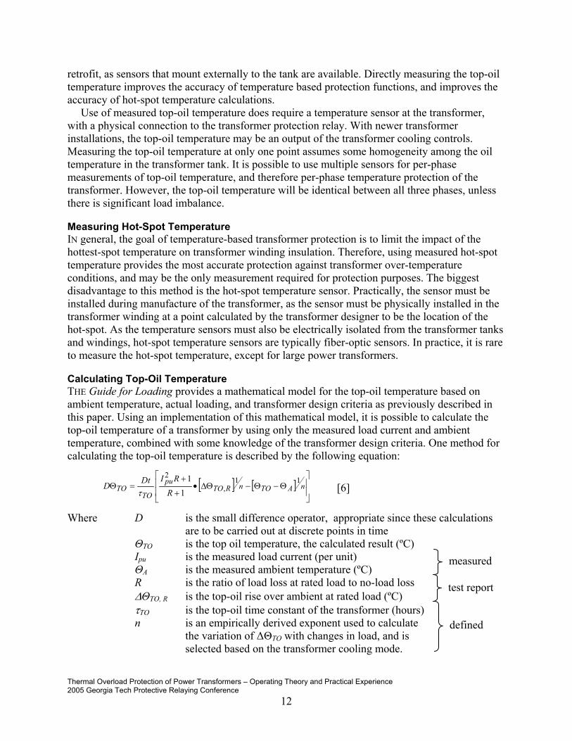
Calculating Top-Oil Temperature THE Guide for Loading provides a mathematical model for the top-oil temperature based on ambient temperature, actual loading, and transformer design criteria as previously described in this paper. Using an implementation of this mathematical model, it is possible to calculate the top-oil temperature of a transformer by using only the measured load current and ambient temperature, combined with some knowledge of the transformer design criteria. One method for calculating the top-oil temperature is described by the following equation:
[ ] [ ]
Θ−Θ−∆Θ•
+
+=Θ nATOnRTO
pu
TOTO R
RIDtD11
,
2
11
τ [6]
Where D is the small difference operator, appropriate since these calculations are to be carried out at discrete points in time
ΘTO is the top oil temperature, the calculated result (ºC) Ipu is the measured load current (per unit)
ΘA is the measured ambient temperature (ºC) R is the ratio of load loss at rated load to no-load loss
∆ΘTO, R is the top-oil rise over ambient at rated load (ºC) τTO is the top-oil time constant of the transformer (hours) n is an empirically derived exponent used to calculate
the variation of ∆ΘTO with changes in load, and is selected based on the transformer cooling mode.
measured
test report
defined

Thermal Overload Protection of Power Transformers – Operating Theory and Practical Experience 2005 Georgia Tech Protective Relaying Conference
13
The variables for this equation are directly measured by the relay (Ipu, θA ), determined from the transformer test report (R, ∆ΘTO, R), or defined by relay settings.
The value for n is determined from the Guide for Loading based on the cooling method of the transformer.
Table 5: Value of the n exponent used in temperature equations
Type of cooling n ONAN 0.8 ONAF 0.9
OFAF / OFWF 0.9 ODAF / ODWF 1.0
The Guide for Loading defines a method to calculate τTO based on transformer test report data
and the cooling method of the transformer.
RT
RTOTO P
C
,
,∆Θ=τ
Where C is the thermal capacity of the transformer (Watt-hours/º C). This value is calculated from the weight of the transformer, amount of insulating oil, and cooling method of the transformer.
∆ΘTO,R is the rated top-oil rise over ambient temperature (ºC) PT,R is the total loss at rated load (watts)
This specific method for calculating the top-oil temperature from the ambient temperature and transformer loading has been proven through field testing to be a reliable method of determining the top-oil temperature of transformers.[7]
Calculating Hot-Spot Temperature AS previously described, the hot-spot temperature is typically calculated, as opposed to directly measured. Repeating the basic model for the hot-spot temperature:
HTOAH ∆Θ+∆Θ+Θ=Θ .
Where ΘH is the winding hottest-spot temperature (ºC) ΘA is the ambient temperature (ºC) ∆ΘTO is the top-oil rise over ambient temperature (ºC) ∆ΘH is the winding hottest-spot rise over top-oil temperature (ºC)
Top-oil measurements, or top-oil temperature calculations as previously described, provide both ambient temperature and the top-oil rise above ambient temperature. Once the top-oil temperature is known, calculating the hot-spot temperature consists of calculating the hot-spot rise above top-oil temperature. As a practical consideration, a transformer protection relay can ignore the ultimate hottest-spot rise over top-oil temperature, and simply focus on the impact of the present transformer load on the hot-spot temperature. The calculation then simply becomes:

Thermal Overload Protection of Power Transformers – Operating Theory and Practical Experience 2005 Georgia Tech Protective Relaying Conference
14
−∆Θ=∆Θ wmRHH K τ
12
, exp1
Where ∆ΘH is the winding hottest-spot rise over top-oil temperature (ºC) ∆ΘH,R is the winding hottest-spot rise over top-oil temperature at rated load
(ºC) K is the ratio of load L to rated load (per unit) τw is the winding time constant at the hot-spot location (hours)
m is an empirically derived exponent used to calculate variation of ∆ΘH with changes in load, and is selected based on the transformer cooling mode.
The variables for this equation are directly measured by the relay (K ), determined from the transformer test report (τw), or defined by relay settings. The value for m is determined from the Guide for Loading based on the cooling method of the transformer.
Table 6: Value of the m exponent used in temperature equations
Type of cooling m ONAN 0.8 ONAF 0.8
OFAF / OFWF 0.8 ODAF / ODWF 1.0
∆ΘH,R, the rated hot-spot rise over top-oil, must be calculated. The rated hot-spot rise is
defined by the equation
RTORAHRH ,,, ∆Θ−∆Θ=∆Θ
Where ∆ΘH,R is the winding hottest-spot rise over top-oil temperature at rated load (ºC)
∆ΘH/A,R is the winding hottest-spot rise over ambient temperature at rated load (ºC)
∆ΘTO, R is the top-oil rise over ambient at rated load (ºC)
∆ΘH/A,R may be provided in the transformer test report. The Guide for Loading, states that a
value of 80º C (for 65º C rise transformers) or 65º C (for 55º C rise transformers) may be used if test data is not available. ∆ΘTO,R is provided by the transformer test report.
Thermal Protection Functions
THERMAL protection functions can be discussed in several broad groups. The first group is “mechanical”, in that physical sensors and relays attempt to detect over-temperatures, and take mitigating action through alarms and tripping. These types of protection functions include direct temperature sensors, internal thermal relays, sudden pressure relays, and gas detection relays. It

Thermal Overload Protection of Power Transformers – Operating Theory and Practical Experience 2005 Georgia Tech Protective Relaying Conference
15
is important to note that the temperature sensors work almost exclusively on top-oil temperature. An important part of this type of protection is the transformer cooling system, as different stages of cooling fans and pumps are started by temperature sensors. Some transformers also use a top-oil temperature monitor that includes contacts that can directly be used for alarming and tripping on oil temperature.
A second group is overcurrent based overload protection, provided by fuses or overcurrent relays. These devices operate when current exceeds a value that is an unacceptable overload on the transformer. This overload will cause oil temperature rise, so the overload functions provide limited thermal protection by de-energizing the transformer.
The protection that is of interest to this paper is the ANSI 49 Thermal Overload function available in modern numerical transformer protection relays. This function, depending on the specific implementation in the relay, uses some combination of measured current, ambient temperature, and transformer oil temperature to detect the presence of an over-temperature condition. The function can then alarm the presence of an over-temperature condition, remove load from the transformer, or trip the transformer off-line.
Typical ANSI 49 Thermal Overload Protection Functions SEVERAL transformer protection relays available today include an ANSI 49 function. The 49 function in these relays routinely include as many as 12 thermal overload stages (49-1 to 49-12), with independent operating settings. This paper describes some typical examples of ANSI 49 function implementation for simplicity, as there are wide variations in the design of the various 49 Thermal Overload functions available on the market.
ANSI 49 Thermal Overload Protection Function Using a Thermal Replica THE basic operating logic of thermal overload protection function using a thermal replica is shown in the SAMA diagram of Figure 7. (See “Symbols” on page 30 for more information on SAMA diagrams). These elements typically only have two operating stages. One stage is typically used for alarming, set at the temperature level equating to 80% to 90% of the maximum current load. The other stage is a final trip stage, set at the maximum allowable operating temperature.
A simple example is applying thermal replica protection on 100 MVA, 500kV/230kV transformer. The transformer is rated at 65º rise above ambient, and uses ONAF cooling.
IFull Load = 115 A At 500 kV Imax = 150 A 130% of full load current τoil = 5 minutes a typical value for hot-spot, based on
size/cooling Alarm stage = 85% a typical value, based on user philosophy Trip stage = 100% maximum overload value

Thermal Overload Protection of Power Transformers – Operating Theory and Practical Experience 2005 Georgia Tech Protective Relaying Conference
16
CTLoad
f(x)Imax
τoil
H/Alarm
Setting
A
A
A
H/ ATrip
Setting
K K
2
max11)(
×=Θ×+
Θ=
II
dtdxf
oiloil ττ
"Alarm" "Trip"
Figure 7: SAMA diagram of ANSI 49 function using a thermal replica
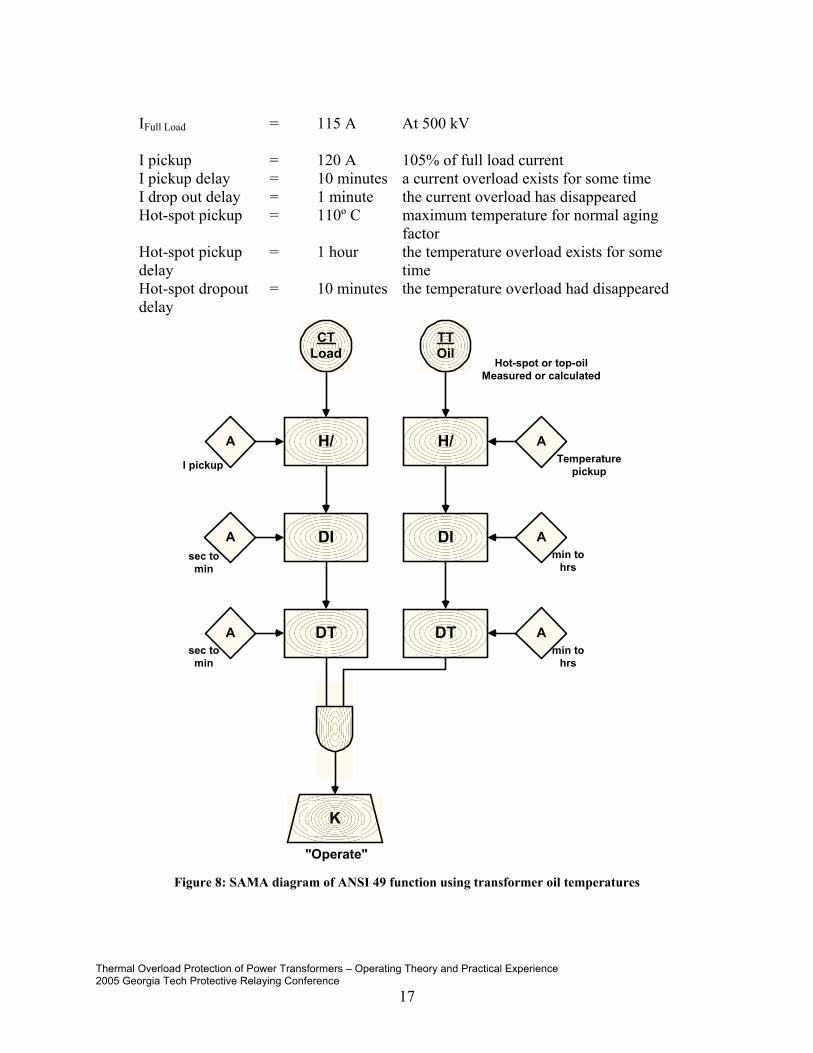
ANSI 49 Thermal Overload Function Using Temperatures THE ANSI 49 Thermal Overload function that is best to apply is one that directly includes oil temperature, either directly measured or calculated, along with load current, in the design of the 49 element algorithm. A typical 49 thermal overload function is shown in the following SAMA diagram of Figure 8.
When actually implemented in a transformer protection relay, the 49 element may be configurable to use either hot-spot temperature or top-oil temperature. Additionally, these functions generally include current supervision. The current supervision is intended to oversee the actual temperature measurement. Oil temperature exceeding normal limits when the current doesn’t exceed the full load rating of the transformer may indicate a failure in the temperature measurement transducer circuit. These types of thermal overload elements are normally set to alarm when over-temperature conditions are reached. Different stages of the 49 element may be set to indicate different transformer criteria. The pickup and dropout delays on temperature are normally set in the minutes to hours range, due to the long time constant of transformer core and winding heating.
Consider the same transformer used in the thermal replica example: a 100 MVA, 500kV/230kV transformer. The transformer is rated at 65º rise above ambient, and uses ONAF cooling. It is desired to set a 49 element to alarm when the hot-spot oil temperature reaches and maintains 110º C, indicated accelerated aging of the transformer has begun.
Thermal Overload Protection of Power Transformers – Operating Theory and Practical Experience 2005 Georgia Tech Protective Relaying Conference
17
IFull Load = 115 A At 500 kV I pickup = 120 A 105% of full load current I pickup delay = 10 minutes a current overload exists for some time I drop out delay = 1 minute the current overload has disappeared Hot-spot pickup = 110º C maximum temperature for normal aging
factor Hot-spot pickup delay
= 1 hour the temperature overload exists for some time
Hot-spot dropout delay
= 10 minutes the temperature overload had disappeared
Figure 8: SAMA diagram of ANSI 49 function using transformer oil temperatures
CTLoad
H/I pickup
DIA
A
H/
min tohrs
K
"Operate"
TTOil
A
DT
sec tomin
sec tomin
DI
DT
Temperaturepickup
min tohrs
A
A
A
Hot-spot or top-oilMeasured or calculated

Thermal Overload Protection of Power Transformers – Operating Theory and Practical Experience 2005 Georgia Tech Protective Relaying Conference
18
Additional settings for calculating temperatures IF the relay calculates the hot-spot temperature, or the top-oil temperature, used in the thermal overload calculations, then there are additional settings required. These settings are used to model the transformer thermal performance in the temperature calculations. The SAMA diagram of Figure 9 shows a calculation method for hot-spot temperature. Hot-spot temperature is the most common temperature to be calculated, due to the practical difficulties of measuring this temperature.
Figure 9: SAMA diagram of hot-spot temperature calculation
To calculate the hot-spot temperature, the transformer relay must measure load current, and must provide the top-oil temperature either through direct measurement, or calculation. Settings
CTLoad
I rated
X2mA
f(x)
A
X
mexponent
f(x)τw
A
Measuredor
calculated
Σ
TTΘTO
∆ΘH,R
A
wxf τ1
exp1)( −=
K
∆ΘH,U
∆ΘH
ΘH
ΘH

Thermal Overload Protection of Power Transformers – Operating Theory and Practical Experience 2005 Georgia Tech Protective Relaying Conference
19
must also provide values for ∆ΘH,R (hot-spot rise over top-oil temperature at rated load), τw (winding time constant at the hot-spot location), and the m exponent (an empirical exponent used to calculate the changes in ∆ΘH with load).
Consider the same transformer used in the thermal replica example: a 100 MVA, 500kV/230kV transformer. The transformer is rated at 65º rise above ambient, and uses ONAF cooling. Settings for the hot-spot temperature calculations are:
m exponent = 0.8 From the Guide for Loading for ONAF transformers
∆ΘH,R = 18º C Calculated from ∆ΘH/A,R = 80º C, and ∆ΘTO,R = 62º C from transformer test report
τw = 0.08 hours transformer test report SOME transformer relays can also calculate the top-oil temperature, using transformer load current and ambient temperature. Just as with calculating hot-spot temperature, some modeling of the transformer thermal performance is required.
The SAMA diagram of Figure 10 of a specific example of a top-oil calculation shows the need for the values of ∆ΘTO,R (top-oil rise above ambient at rated load), R (ratio of copper loss to core loss), the n exponent (an empirically derived exponent used to calculate the variation of ∆ΘTO with changes in load), and τTO (the top-oil time constant for the transformer).
Consider the same transformer used in the previous examples: a 100 MVA, 500kV/230kV transformer. The transformer is rated at 65º rise above ambient, and uses ONAF cooling. Settings for the inputs to the top-oil temperature calculations look like:
∆ΘTO,R = 62º C (from the transformer test report) R = 1.66 (calculated from the transformer test
report) n exponent = 0.9 (From the Guide for Loading for ONAF
transformers) τTO = 16.3 hours (calculated from transformer test report
and nameplate data)

Thermal Overload Protection of Power Transformers – Operating Theory and Practical Experience 2005 Georgia Tech Protective Relaying Conference
20
Figure 10: SAMA diagram of transformer top-oil temperature calculation
Northeast Utilities: A Practical Setting Method for Thermal Overload Protection
UNDERSTANDING the basics of the cause and effects of transformer oil temperatures, and how the ANSI 49 Thermal Overload function is implemented in a specific relay, is only a prelude to the practical matter of determining appropriate settings for transformer protection. Northeast Utilities Systems has applied the 49 thermal overload function provided in a transformer protection relay as part of an automatic load transfer scheme. The operation of a 49 element due to an over-temperature condition in the transformer initiates a transfer of load.
CTLoad
I rated
f(x)
f(x)
A
f(x)
nexponent
τTO
Measured
Σ
∆ΘTO,R
A TOxf τ1
exp1)( −=
K
∆ΘTO,U
∆ΘTO
ΘTO
ΘTO
R
f(x) A
( )
n
RTO R
RKxf
+
+
∆Θ=1
1)(
2
,
τTO
AA
A
TAmbient
TOxf τ1
exp1)( −=
Thermal Overload Protection of Power Transformers – Operating Theory and Practical Experience 2005 Georgia Tech Protective Relaying Conference
21
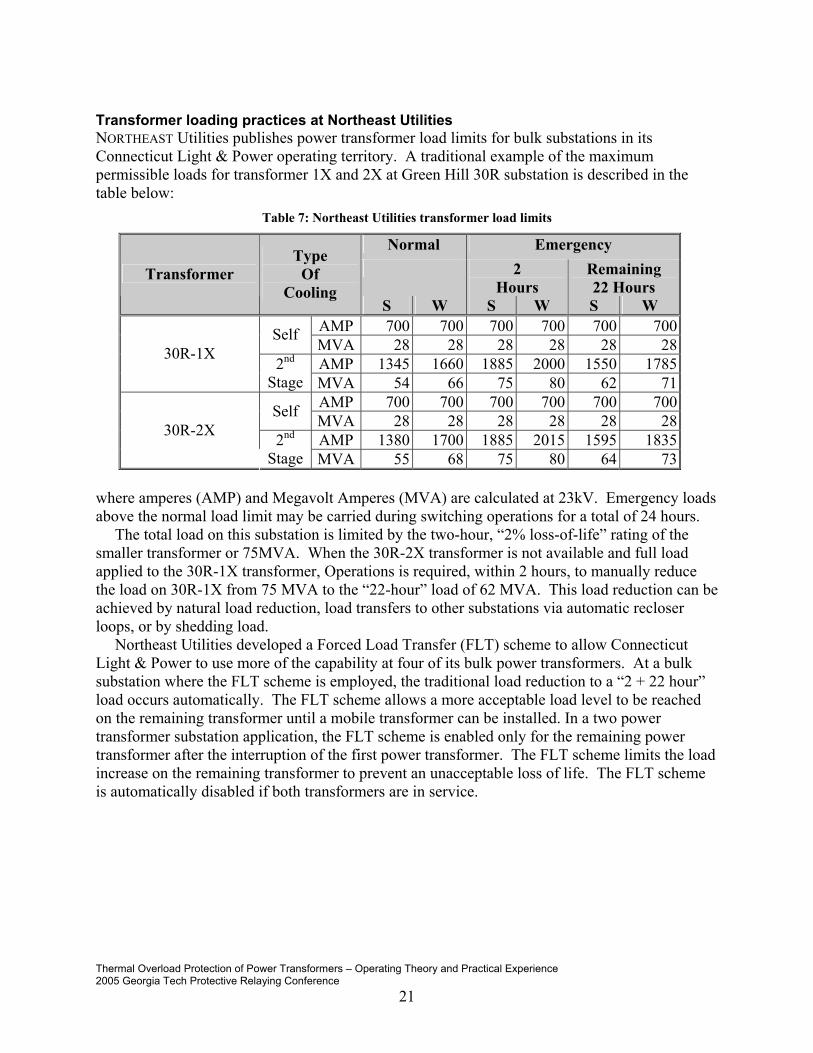
Transformer loading practices at Northeast Utilities NORTHEAST Utilities publishes power transformer load limits for bulk substations in its Connecticut Light & Power operating territory. A traditional example of the maximum permissible loads for transformer 1X and 2X at Green Hill 30R substation is described in the table below:
Table 7: Northeast Utilities transformer load limits
Normal Emergency 2
Hours Remaining 22 Hours
Transformer Type
Of Cooling
S W S W S W AMP 700 700 700 700 700 700Self MVA 28 28 28 28 28 28AMP 1345 1660 1885 2000 1550 178530R-1X 2nd
Stage MVA 54 66 75 80 62 71AMP 700 700 700 700 700 700Self MVA 28 28 28 28 28 28AMP 1380 1700 1885 2015 1595 183530R-2X 2nd
Stage MVA 55 68 75 80 64 73 where amperes (AMP) and Megavolt Amperes (MVA) are calculated at 23kV. Emergency loads above the normal load limit may be carried during switching operations for a total of 24 hours.
The total load on this substation is limited by the two-hour, “2% loss-of-life” rating of the smaller transformer or 75MVA. When the 30R-2X transformer is not available and full load applied to the 30R-1X transformer, Operations is required, within 2 hours, to manually reduce the load on 30R-1X from 75 MVA to the “22-hour” load of 62 MVA. This load reduction can be achieved by natural load reduction, load transfers to other substations via automatic recloser loops, or by shedding load.
Northeast Utilities developed a Forced Load Transfer (FLT) scheme to allow Connecticut Light & Power to use more of the capability at four of its bulk power transformers. At a bulk substation where the FLT scheme is employed, the traditional load reduction to a “2 + 22 hour” load occurs automatically. The FLT scheme allows a more acceptable load level to be reached on the remaining transformer until a mobile transformer can be installed. In a two power transformer substation application, the FLT scheme is enabled only for the remaining power transformer after the interruption of the first power transformer. The FLT scheme limits the load increase on the remaining transformer to prevent an unacceptable loss of life. The FLT scheme is automatically disabled if both transformers are in service.

Thermal Overload Protection of Power Transformers – Operating Theory and Practical Experience 2005 Georgia Tech Protective Relaying Conference
22
52
52
5252
52
1X 2X
30R7 30R13
Top-oil49-1
49-7
Top-oil 49-1
49-7
Green Hill 30RSubstation
115 kV 115 kV
23 kV
Figure 11: Green Hill 30R Substation
One of the five substations where the FLT scheme is in use is at the Green Hill 30R Substation. Using the thermal overload 49 elements of the transformer relay, control logic is integrated into existing substation controls. The 30R-1X transformer is permitted to operate at loads that are not described by NU’s traditional load limits, following the loss of the 30R-2X transformer. This protection scheme uses 7 thermal overload elements, with settings as described below. If the load and temperature criteria are met for one of the seven thermal settings of the 30R-1X transformer, one distribution feeder, 30R13, is automatically interrupted by the FLT scheme. Recloser auto-loops on the feeder transfers load to other substations. Once the auto-loops have operated and load is transferred, the feeder is closed to restore any load that was not transferred.

Thermal Overload Protection of Power Transformers – Operating Theory and Practical Experience 2005 Georgia Tech Protective Relaying Conference
23
Table 8: Northeast Utilities 49 function settings
30R-1X
Thermal Setting # Description MVA
Top Oil Temp °C
Time Delay
High Side Amps
Low Side Amps Comments
49-1
Summer Normal Limit 55.0 87
4 Hours 289 1381
Calculated normal limit based on 25°C ambient. Top oil temperature limit is based on predicted temp shown by load program. At 55 MVA, hot spot rise is 33°C above top oil temp. Hot spot temp of 120°C for 4 hours will result in no appreciable loss of life.
49-2 ANSI Max 93.4 85 1
Minute 490 2345
Based on ANSI 2x Nameplate limit. (C57.91-1995, Table7). 1 minute limit is based on the need to take immediate action since winding hot spot temperature is predicted to exceed 180°C. This setpoint basically functions as a backup to the overcurrent protection.
49-3 Max Top Oil 60.0 105 1
Minute 315 1506
Based on ANSI C57.91-1995, Table 8. ANSI states that the top oil temperature should never be allowed to exceed 110°C. Above 60 MVA and 32°C ambient, the cooling system will not be able to keep up with the heat input from the copper losses. This situation will not result in a loss of life, but the load must be reduced to prevent runaway.
49-4
Winter Normal Limit 67.9 70
8 Hours 356 1704
Calculated normal limit based on 0°C ambient. The load program predicts that the cooling system will keep up at this ambient temperature as long as the load is kept below the setpoint. At this load, there should be no appreciable loss of life.
49-5 Summer Step 1 60.0 87
3 Hours 315 1506
At 60 MVA, hot spot rise is 38°C above top oil temp. Hot spot temp of 125°C for 3 hours will result in no appreciable loss of life.
49-6 Summer Step 2 65.0 92
2 Hours 341 1632
At 65 MVA, hot spot rise is 43°C above top oil temp. Hot spot temp of 135°C for 2 hours will result in no appreciable loss of life.
49-7 Summer Step 3 70.0 91 1 Hour 367 1757
At 70 MVA, hot spot rise is 49°C above top oil temp. Hot spot temp of 140°C for 1 hour will result in no appreciable loss of life.
Should any of the seven criteria persist after the first feeder is interrupted, the FLT scheme
automatically interrupts a second feeder, 30R7. Recloser auto-loops on this feeder operate as previously described, transferring load to other substations, and the feeder is automatically reclosed to restore any load that was not transferred.

Thermal Overload Protection of Power Transformers – Operating Theory and Practical Experience 2005 Georgia Tech Protective Relaying Conference
24
49-1 Trip
49-2 Trip
49-3 Trip
49-4 Trip
49-5 Trip
49-6 Trip
49-7 Trip
Bkr 52/2X Closed
Top-oil sensor failure
Over-temperaturecondition
52/30R13 Trip Cutoff
FLT Scheme On
An over-temperature conditionexists when a 49 elementtrips, the other transformer isout of service, and the top-oiltemperature sensor isfunctional
1 sec
0Trip 30R13
Trip 30R13
Shed one circuit load whenover-temperature conditionexists, FLT scheme is on, andbreaker is ready.
Scheme Reset
S
Q
Q
R
SET
CLR
60 s
1 sReset 30R13
Close circuit breaker afterload is transferred to othercircuit via loop reclosers
52/30R13 Trip Cutoff
1 sec
0Trip 30R7
Shed second circuit load whenover-temperature conditionstill exists, FLT scheme is on,and breaker is ready.
S
Q
Q
R
SET
CLR
60 s
1 sReset 30R7
Close circuit breaker afterload is transferred to othercircuit via loop reclosers
Figure 12: FLT scheme logic (simplified)
Care is taken to select feeder circuits such that the load from one FLT scheme does not overwhelm the receiving substations. Recloser auto-loop scheme coordination is also verified to confirm that the reclosers’ settings allow the load increase.
The traditional transformer ratings are based on temperature conditions expected to occur in a transformer for certain loads and an assumed ambient temperature. Summer and winter limits are the load limits to choose from. The ‘ANSI Max’ setting is a critical temperature alarm, as this temperature will rapidly cause failure of the transformer. The philosophy of NU for summer conditions is to start transferring load more rapidly as top-oil temperature increases. NU is also using measured load current as part of the criteria for transferring load.
The transformer protection relay is critical to allowing more transformer capacity by accepting an accurate transformer top-oil temperature input and measuring the ambient temperature. The transformer’s thermal characteristics are also programmed into the relay. Therefore the relay can better monitor actual transformer conditions, allowing increased transformer loading, reduction of transformer load when needed, and preventing damaging conditions from occurring. The relay used by NU calculates hot-spot temperature from the top-oil temperature, load current, and transformer design characteristics. However, NU has chosen to use the directly measured top-oil temperature as the key temperature criteria for the FLT.

Thermal Overload Protection of Power Transformers – Operating Theory and Practical Experience 2005 Georgia Tech Protective Relaying Conference
25
It is the operational intent to allow the FLT scheme to operate automatically as designed. Operators should not reduce load manually even if loads exceed the traditional limits in Table 7 above.
Figure 13: Part of FLT scheme in relay logic
For this application, only the ANSI 49 functions are enabled in the relay, as this scheme is part of a pilot program. Transformer overcurrent and differential protection is performed by other relays, allowing Northeast Utilities to evaluate the thermal overload protection and FLT scheme separately from the traditional transformer protection.
Operations receive several different indications from the FLT scheme. Notifications include: - the FLT scheme is out of service, - one of the seven 49 criteria has been met for MVA and temperature, - a feeder has tripped by the FLT scheme (not by other protection) and - FLT ambient and top oil probe failure - 30 minute predictive transformer overload early warning alarm, - 15 minute predictive transformer overload early warning alarm The relay used by NU also includes predictive alarming functions based on calculated loss-of-
life and hot-spot temperatures, indicated by these last 2 alarms. These predictive alarms are described in this paper.

Thermal Overload Protection of Power Transformers – Operating Theory and Practical Experience 2005 Georgia Tech Protective Relaying Conference
26
0 30-300
1
2
10 20 40 50-10-20-40
0.2
0.4
0.6
0.8
1.2
1.4
1.6
1.8
Ambient Temperature degrees C
Allo
wed
load
ing
per u
nit
FAA = 64
FAA = 8
FAA = 1
at 10O, pickup is~1.2 per unit
at 40O, pickup is~0.9 per unit
Other possible uses for temperature
THIS paper has focused on the ANSI 49 Thermal Overload protection function, because this protection is readily available in numerical transformer protection relays, and because this protection function is very traditional in nature. The 49 function is traditional in that the settings are static, pre-determined to respond when certain measured criteria are met. However, numerical relays allow the use of dynamic settings, and also predictive alarming functions. This is due in part to the ability of some relays to calculate temperatures and loss-of-life into the future, and because the rate of change of oil temperature in transformers is measured in hours. Therefore, temperature based protection functions in numerical relays can become pro-active, and operate before over-temperature conditions occur. In addition, the temperature and load data used for the temperature protection functions can be included in SCADA applications, metering applications, and trend recording applications.
51ADP Adaptive Overload Protection The 51ADP function is a dynamic protection function that automatically adapts transformer overload protection for changes in ambient temperature. Transformer overload relays traditionally are inverse time overcurrent elements (ANSI 51), set with a pickup at some multiple of transformer full load operating current, based on the transformer nameplate ratings. However, as this paper describes, the true full load rating of the transformer is impacted by ambient temperature conditions. Northeast Utilities Systems, for example, has over a 300 amp difference between the summer full load rating of 1380 amps, and the winter full load ratings of 1700 amps, on the low voltage side of a 55MVA transformer.
The parameters of the 51ADP function have been defined by a working group of the IEEE Power System Relay Committee in the report “Adaptive Transformer Thermal Overload Protection” [3]. The 51ADP function, as implemented in one instance, requires direct measurement of the ambient temperature by the transformer relay, and has only one setting, which is a per unit loss-of-life factor. When the accelerated aging factor FAA exceeds this per unit setting, the 51ADP function dynamically adjusts its pickup setting based on ambient temperature. As temperature increase, the pickup decreases, and vice-versa. This permits the transformer overload protection to be precisely tuned to actual operating states. This concept was presented to the Georgia Tech Protective Relay Conference in 1998. [5]
Figure 14: Dynamic adjustment of overload pickup setting

Thermal Overload Protection of Power Transformers – Operating Theory and Practical Experience 2005 Georgia Tech Protective Relaying Conference
27
Predictive Overload Functions THE long time constant of changes in transformer insulating oil temperatures, along with the calculation capabilities of a microprocessor, allow the use of predictive overload functions for transformer protection. Assuming the present load conditions, and ambient temperature, will remain constant, the hot-spot or top-oil temperature can be calculated for some point in time in the future, using the temperature models outlined in this paper. More importantly, the time to reach a specific hot-spot temperature can be calculated, which permits the assertion of alarms in advance of actual over-temperature conditions being reached. This possibility allows transformer protection to become proactive as opposed to reactive. Such proactive functions have been implemented in the transformer relay used by Northeast Utilities, and could be implemented in SCADA as well.
Figure 15: Predictive thermal overload protection function
Loss-of-life protection functions THE key goal of implementing thermal overload protection functions is to limit the loss-of-life of the transformer winding insulation. As described in the Guide for Loading, and this paper, it is possible to determine the accelerated aging factor FAA for a specific temperature condition, and a total loss-of-life factor when compared to the transformer life expectancy of 65,000 hours. A relay that calculates a discrete loss-of-life could then use some value of loss-of-life, say 24 hours total loss-of-life, as a setpoint for an alarm for an over-temperature condition. The following Figure 16 illustrates the basic principle of this function.
Time
Temp
Trip
Time to reachtrip temperature
assuming I and ΘA areconstant
Now

Thermal Overload Protection of Power Transformers – Operating Theory and Practical Experience 2005 Georgia Tech Protective Relaying Conference
28
Figure 16: Loss-of-life protection function principle
The ANSI 49 function operates at some specific temperature condition. However, the total loss-of-life for an event that exceeds the normal life expectancy loading limit of 110º C, but never exceeds a 49 element operating temperature, can be much more damaging to the transformer. The transformer protection relay applied by Northeast Utilities has actually implemented such a function. It is possible to make this loss-of-life function a proactive function, by alarming before the total loss-of-life for a specific temperature event is reached.
Figure 17: Loss-of-life alarm function settings
Metering / SCADA / Trend recording TRANSFORMER relays using the 49 Thermal Overload protection function are using load current, ambient temperature, top-oil temperature, and hot-spot temperature. It is obvious these temperatures can be made available as metering information and therefore available to SCADA.
Time
Hot SpotTemp
110O
Time
TotalLOL
LOLTrip
Trip
Time to reachtrip temperature
assuming I and ΘA areconstant
Now

Thermal Overload Protection of Power Transformers – Operating Theory and Practical Experience 2005 Georgia Tech Protective Relaying Conference
29
It is a straight-forward application to also provide trend recording, storing oil temperatures, loss-of-life, and load current at regular intervals. These capabilities can make a transformer protection relay a good choice to provide basic transformer monitoring on transformers where a full-blown transformer monitoring system is not justified.
Final Thoughts
THE practical ability for thermal overload protection of transformers exists in most numerical transformer protection relays available today. The authors strongly believe these functions should be applied, as the functions help reduce the accelerated aging of power transformers during overload conditions at very low cost and at low effort. Northeast Utilities Systems is applying these functions as part of a total scheme to maximize transformer operating life.
The loading philosophy applied by NU is one possible philosophy when determining settings for the 49 elements in a transformer relay. A similar method is described in 3.11 Loading Power Transformers of [2]. For readers wishing a better understanding of power transformers, and the impact of operating oil temperature, the authors highly recommend the Guide for Loading [1], the Transformers chapter of the Electric Power Engineering Handbook [2], and the Adaptive Transformer Thermal Overload Protection [3] report from the PSRC.

Thermal Overload Protection of Power Transformers – Operating Theory and Practical Experience 2005 Georgia Tech Protective Relaying Conference
30
Symbols
Some of the functions described in this paper are non-linear in nature. Linear Boolean logic symbols commonly used in system protection diagrams are not adequate to truly represent these functions. The process control industry has developed symbols and diagramming formats to represent non-linear processes. The symbols and diagramming format are commonly known as “SAMA diagrams”, as they were originally a standard developed by the Scientific Apparatus Makers Association. Though the Scientific Apparatus Makers Association has declared the original standard obsolete, and no longer permits the direct association of the organization name with the industry standard, these symbols, and the term “SAMA diagram”, are still in common use in the process control industry.. It is the opinion of the authors that protection engineers need to become familiar with these symbols, as protection systems migrate from traditional protection and control to automatic process control.
Measuring
Symbol Function
Setpoint
Automatic Signal Processing
Final Controlling
A Analog
f(x) Non-linear function
H/ High signal monitor
K Proportional
DI Time delay on initiation
DT Time delay on termination
X2m
X
Σ
Symbol Function
Dividing
Exponential
Multiplying
Summing

Thermal Overload Protection of Power Transformers – Operating Theory and Practical Experience 2005 Georgia Tech Protective Relaying Conference
31
References
[1] IEEE Guide for Loading Mineral-Oil Immersed Power Transformers, IEEE Standard C57.91, Institute of Electrical and Electronic Engineers, New York NY, 1995.
[2] L. L. Grigsby, editor, The Electric Power Engineering Handbook, CRC Press, Boca Raton, FL, 2001.
[3] Adaptive Transformer Thermal Overload Protection, Final Report of IEEE Power System Relaying Committee Working Group K3, IEEE Power Engineering Society Power System Relay Committee Report, January, 1999.
[4] IEEE Guide for Protective Relay Applications to Power Transformers, IEEE Standard C57.91, Institute of Electrical and Electronic Engineers, New York NY, 2000.
[5] G. Swift, D. Fedirchuk, Z. Zhang, A New Relaying Principle for Transformer Overload Protection, 52nd Annual Georgia Tech Protective Relaying Conference, May 6-8, 1998.
[6] G. Swift, T. S. Molinski, W. Lehn, A Fundamental Approach to Transformer Thermal Modeling – Part I: Theory and Equivalent Circuit, IEEE Transactions On Power Delivery, Vol. 16, No. 2, April 2001, pp. 171 – 175.
[7] G. Swift, T. S. Molinski, R. Bray, R. Menzies, A Fundamental Approach to Transformer Thermal Modeling – Part II: Field Verification, IEEE Transactions On Power Delivery, Vol. 16, No. 2, April 2001, pp. 171 – 180.
[8] SIPROTEC 7UT612 Differential Protection Relay Instruction Manual, Siemens AG, Nuremburg, Germany, 2002.
[9] T-PRO Transformer Protection Relay User Manual Version 3.3 Rev 1, NxtPhase T&D Corporation, Vancouver, BC, 2003.
[10] Functional Diagramming of Instrument and Control Systems, The Measurement, Control & Automation Association, Williamsburg, VA, 1981.
Special thanks to Wayne Hartmann as the original author of some of the drawings.

Thermal Overload Protection of Power Transformers – Operating Theory and Practical Experience 2005 Georgia Tech Protective Relaying Conference
32
About the Authors
Mike Giordano, P.E. is presently an Electrical Engineer in the Distribution Engineering & Design Protection and Control department of Northeast Utilities Systems, responsible for substation controls design, transformer protective relay scheme design, distribution protection design, and distribution automation system design. Mike has also extensive experience in the Electrical Test and Engineering group of NU. In addition, Mike is a Certified Firefighter I and Incident Safety Officer from the National Fire Academy, and a licensed Professional Engineer in the State of Connecticut. Rich Hunt, M.S., P.E. is presently a Senior Field Application Engineer for NxtPhase T&D Corporation, responsible for technical marketing, technical sales, and technical support of optical current and voltage sensors, and protective relays and fault recorders. Rich has over 10 years of utility experience at Virginia Power and the University of North Carolina, as well as over 6 years of industry experience. Rich earned his M.S.E.E at Virginia Tech under the guidance of Dr. Arun Phadke, with a thesis topic entitled “Hidden Failure in Protective Relays: Supervision and Control”. Rich is a member of the Main Committee of the IEEE PSRC, and is a Professional Engineer licensed in the Commonwealth of Virginia.