thermal mass flowmeter sensyflow fmt400-vts, fmt400 …thermal flow metering procedures us e...
TRANSCRIPT
— ABB Limited Measurement & Analytics Howard Road, St. Neots Cambridgeshire, PE19 8EU UK Tel: +44 (0)870 600 6122 Fax: +44 (0)1480 213 339 Email: [email protected] ABB Automation Products GmbH Measurement & Analytics Schillerstr. 72 32425 Minden Germany Tel: +49 571 830-0 Fax: +49 571 830-1806 abb.com/flow
ABB Inc. Measurement & Analytics 125 E. County Line Road Warminster, PA 18974 USA Tel: +1 215 674 6000 Fax: +1 215 674 7183
10/1
4-6.
22-E
N R
ev. H
0
3.20
19
— We reserve the right to make technical changes or modify the contents of this document without prior notice. With regard to purchase orders, the agreed particulars shall prevail. ABB does not accept any responsibility whatsoever for potential errors or possible lack of information in this document. We reserve all rights in this document and in the subject matter and illustrations contained therein. Any reproduction, disclosure to third parties or utilization of its contents – in whole or in parts – is forbidden without prior written consent of ABB. © ABB 2019 3KXF421002R1001
— ABB MEASUREMENT & ANALYTICS | DATA SHEET
Sensyflow FMT400-VTS, FMT400-VTCS Thermal Mass Flowmeter

2 SENSYFLOW FMT400-VTS, FMT400-VTCS THERMAL MASS FLOWMETER | 10/14-6.22-EN REV. H SENSYFLOW FMT400-VTS, FMT400-VTCS THERMAL MASS FLOWMETER | 10/14-6.22-EN REV. H 4
— Measurement made easy
— Direct mass flow measurement of gases • No additional pressure and temperature compensation
— Wide measuring range up to 1:100
— High measuring accuracy
— Quick response time ≤ 0.5 s
— Negligible pressure loss
— No moving parts, no wear, maintenance-free
— Defined and reproducible mounting position in the middle of the pipeline
Thermal Mass Flowmeter Sensyflow FMT400-VTS, FMT400-VTCS 10/14-6.22-EN for gases, integral mount design
3
Contents 1 General information ............................................................................................................................................ 4
1.1 Principle of operation and construction .......................................................................................................... 4
1.2 Type overview ................................................................................................................................................ 5
1.3 Overview Sensyflow FMT400-VTS, version for process engineering ............................................................ 5
1.4 Overview Sensyflow FMT400-VTCS, hygienic version .................................................................................. 6
2 Specifications ...................................................................................................................................................... 7
2.1 Parameterization ............................................................................................................................................ 8
3 Sensyflow FMT400-VTS, version for process engineering ............................................................................. 9
3.1 Dimensions ..................................................................................................................................................... 9
3.2 Installation instructions ................................................................................................................................. 10
3.3 Ordering information ..................................................................................................................................... 14
3.4 Additional ordering information for calibration .............................................................................................. 16
4 Sensyflow FMT400-VTCS, hygienic version ................................................................................................... 17
4.1 Dimensions ................................................................................................................................................... 17
4.2 Measuring ranges at atmospheric pressure ................................................................................................. 18
4.3 Ordering information ..................................................................................................................................... 19
4.4 Additional ordering information for calibration .............................................................................................. 20
5 Electrical connections ...................................................................................................................................... 21
6 Recommended steadying lengths according to DIN EN ISO 5167-1 ........................................................... 22
7 Questionnaire .................................................................................................................................................... 23
Data Sheet Thermal Mass Flowmeter Sensyflow FMT400-VTS, FMT400-VTCS
for gases, integral mount design
Thermal Mass Flowmeter Sensyflow FMT400-VTS, FMT400-VTCS 10/14-6.22-EN for gases, integral mount design
4
1 General information
1.1 Principle of operation and construction Change from one to two columns
The devices of the Sensyflow FMT400-series operate according to the thermal measuring principle of a hot film anemometer. This measuring method determines the gas mass flow directly. Taking the standard density of the gases into consideration, the standard volume flow rate can be displayed without additional pressure and temperature compensation.
Sensyflow FMT400-VTS is used in the field of process engineering and Sensyflow FMT400-VTCS in the food and beverage industry for flow measurement of gases and gas mixtures.
The measuring systems of the FMT400 series are made up of a transmitter, flowmeter sensor and a pipe component. The transmitter directly delivers an electrically isolated 0/4 ... 20 mA output signal. The flowmeter sensor is designed as flange-mounted and is installed in the pipe component in a defined way.
The pipe component is available in nominal diameters ranging from DN 25 ... DN 200 (1 ... 8”) and in various designs. It is also possible to install the flowmeter sensor in square ducts or pipes of any diameter by using a weld-on adapter.
Physics of measurement
Thermal flow metering procedures use different ways to evaluate the flow dependent cooling of a heated resistor as measuring signal.
In a hotfilm anemometer with temperature difference control, the heated platinum resistor is maintained at a constant overtemperature in relation to an unheated platinum sensor inside the gas flow. The heating power required for maintaining the overtemperature depends directly on the flow rate and the material properties of the gas. With a known (and constant) gas composition the mass-flow can be deter-mined by electronically evaluating the heater current/mass-flow curve without additional pressure and temperature compensation.
Together with the standard density of the gas this results directly in the standard volume flow. Considering the high measuring range dynamics up to 1:150, an accuracy smaller than 1 % of the measuring value is achieved.
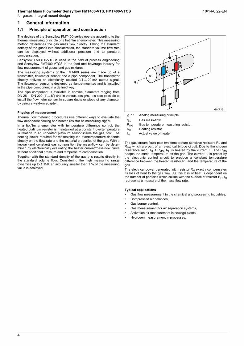
Fig. 1: Analog measuring principle
qm RMG RH IH
Gas mass-flow Gas temperature measuring resistor Heating resistor Actuel value of heater
The gas stream flows past two temperature-sensitive resistors RH and RMG which are part of an electrical bridge circuit. Due to the chosen resistance ratio RH < RMG, RH is heated by the current IH, and RMG adopts the same temperature as the gas. The current IH is preset by the electronic control circuit to produce a constant temperature difference between the heated resistor RH and the temperature of the gas. The electrical power generated with resistor RH exactly compensates its loss of heat to the gas flow. As this loss of heat is dependent on the number of particles which collide with the surface of resistor RH, IH represents a measure of the mass flow rate.
Typical applications
• Gas flow measurement in the chemical and processing industries,
• Compressed air balances,
• Gas burner control,
• Gas measurement for air separation systems,
• Activation air measurement in sewage plants,
• Hydrogen measurement in processes.
Change from one to two columns
Thermal Mass Flowmeter Sensyflow FMT400-VTS, FMT400-VTCS 10/14-6.22-EN for gases, integral mount design
5
1.2 Type overview
Type FMT400-VTS FMT400-VTCS
Hygienic version
Application Process engineering Food and beverage industry
Measured gases Flow rate of gases and gas mixtures with known composition
Flow rate of air, N2, CO2, O2
Explosion protection Manufacturer’s Declaration zone 2 / 22
II 3G EEx nA ib II T4; II 3D T 135°C IP 65
Design / Dimensions / Weight dependent on nominal size
Material (standard) 1.4571, Ceramics Stainless steel e. g. 1.4301
Process connection (standard) Flange acc. to EN1092-1 form B1, PN 40 (DIN 2635 form C) or ASME B 16.5 Cl. 150 / 300
Pipe fitting S acc. to DIN 11851 or FG flange
System components Transmitter
Flowmeter sensor
Pipe component, design 1 or 2 or weld-on adapter
Transmitter
Flowmeter sensor
Pipe component
Standard nominal pipe sizes Pipe component design 1: wafer flange DN 40, 50, 65, 80, 100, 125, 150, 200 – ASME 1 1/2“, 2“, 3“, 4“, 6“, 8“
Pipe component design 2: partial measuring section DN 25, 40, 50, 65, 80 – ASME 1“, 1 1/2“, 2“
Weld-on adapter for square ducts or pipe diameters ≥ DN 100 (4”)
Pipe component hygienic version: partial measuring section DN 25, 40, 50, 80
Degree of protection IP 65 / NEMA 4X
1.3 Overview Sensyflow FMT400-VTS, version for process engineering
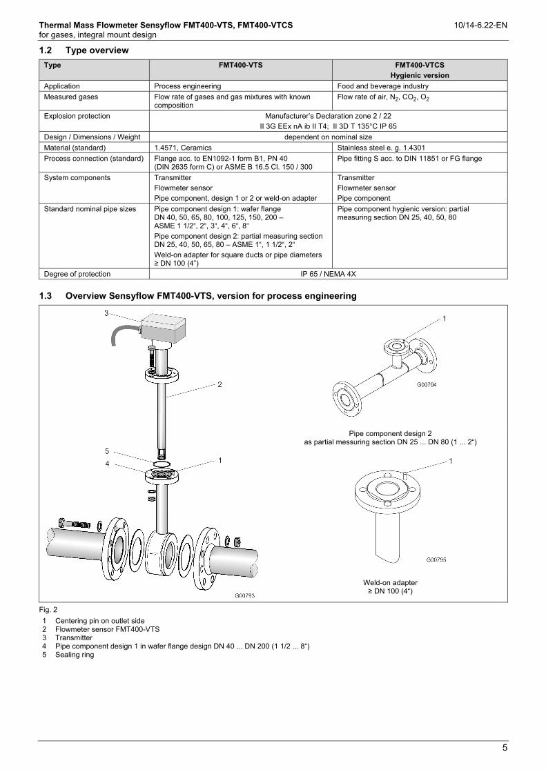
Pipe component design 2
as partial messuring section DN 25 ... DN 80 (1 ... 2“)
Weld-on adapter ≥ DN 100 (4“)
Fig. 2
1 Centering pin on outlet side 2 Flowmeter sensor FMT400-VTS 3 Transmitter 4 Pipe component design 1 in wafer flange design DN 40 ... DN 200 (1 1/2 ... 8“) 5 Sealing ring
Thermal Mass Flowmeter Sensyflow FMT400-VTS, FMT400-VTCS 10/14-6.22-EN for gases, integral mount design
6
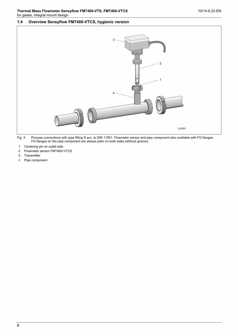
1.4 Overview Sensyflow FMT400-VTCS, hygienic version
Fig. 3: Process connections with pipe fitting S acc. to DIN 11851. Flowmeter sensor and pipe component also available with FG flanges. FG flanges on the pipe component are always plain on both sides (without groove).
1 Centering pin on outlet side2 Flowmeter sensor FMT400-VTCS
3 Transmitter
Pipe component
Thermal Mass Flowmeter Sensyflow FMT400-VTS, FMT400-VTCS 10/14-6.22-EN for gases, integral mount design
7
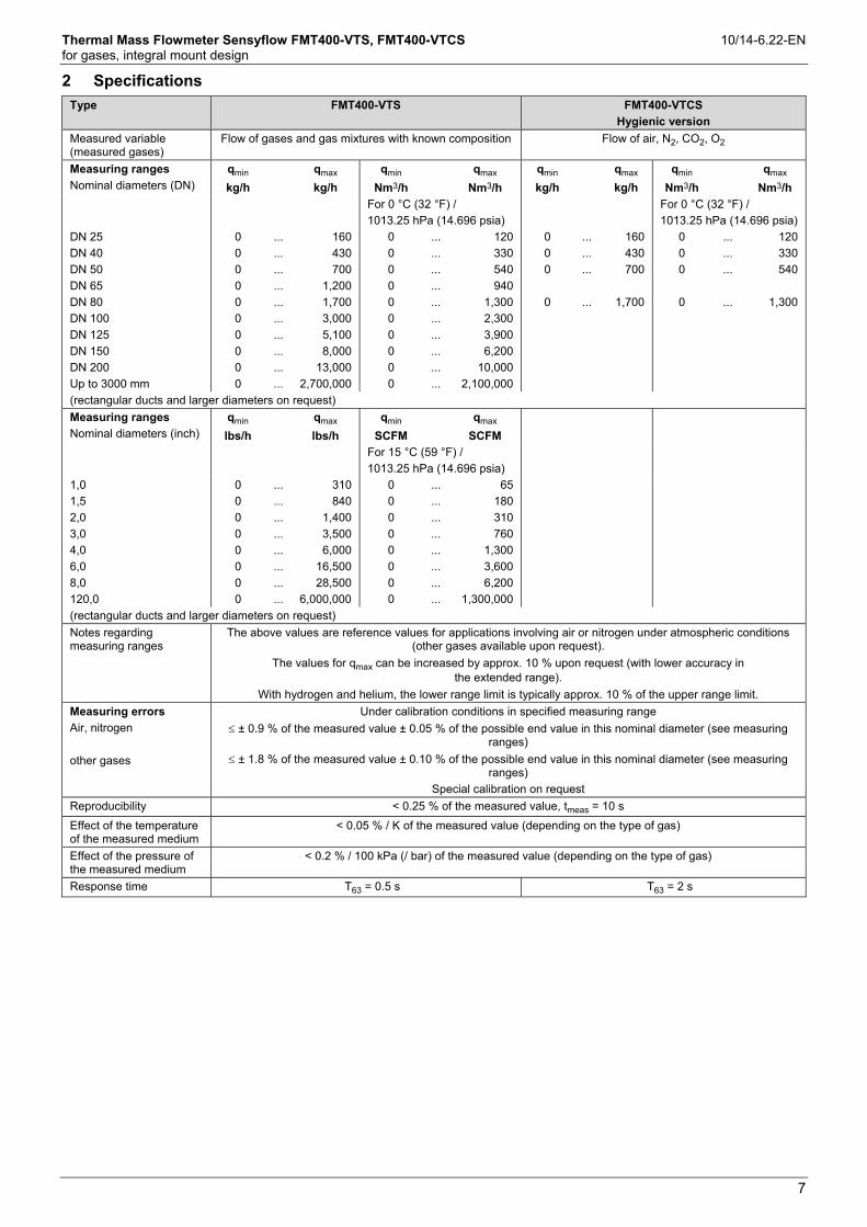
2 Specifications
Type FMT400-VTS FMT400-VTCS
Hygienic version
Measured variable (measured gases)
Flow of gases and gas mixtures with known composition Flow of air, N2, CO2, O2
Measuring ranges
Nominal diameters (DN)
qmin
kg/h
qmax
kg/h
qmin
Nm3/h
qmax
Nm3/h
qmin
kg/h
qmax
kg/h
qmin
Nm3/h
qmax
Nm3/h
For 0 °C (32 °F) /
1013.25 hPa (14.696 psia)
For 0 °C (32 °F) /
1013.25 hPa (14.696 psia)
DN 25
DN 40
DN 50
DN 65
DN 80
DN 100
DN 125
DN 150
DN 200
Up to 3000 mm
0
0
0
0
0
0
0
0
0
0
...
...
...
...
...
...
...
...
...
...
160
430
700
1,200
1,700
3,000
5,100
8,000
13,000
2,700,000
0
0
0
0
0
0
0
0
0
0
...
...
...
...
...
...
...
...
...
...
120
330
540
940
1,300
2,300
3,900
6,200
10,000
2,100,000
0
0
0
0
...
...
...
...
160
430
700
1,700
0
0
0
0
...
...
...
...
120
330
540
1,300
(rectangular ducts and larger diameters on request)
Measuring ranges
Nominal diameters (inch)
qmin
lbs/h
qmax
lbs/h
qmin
SCFM
qmax
SCFM
For 15 °C (59 °F) /
1013.25 hPa (14.696 psia)
1,0
1,5
2,0
3,0
4,0
6,0
8,0
120,0
0
0
0
0
0
0
0
0
...
...
...
...
...
...
...
...
310
840
1,400
3,500
6,000
16,500
28,500
6,000,000
0
0
0
0
0
0
0
0
...
...
...
...
...
...
...
...
65
180
310
760
1,300
3,600
6,200
1,300,000
(rectangular ducts and larger diameters on request)
Notes regarding measuring ranges
The above values are reference values for applications involving air or nitrogen under atmospheric conditions (other gases available upon request).
The values for qmax can be increased by approx. 10 % upon request (with lower accuracy in the extended range).
With hydrogen and helium, the lower range limit is typically approx. 10 % of the upper range limit.
Measuring errors
Air, nitrogen
other gases
Under calibration conditions in specified measuring range
± 0.9 % of the measured value ± 0.05 % of the possible end value in this nominal diameter (see measuring ranges)
± 1.8 % of the measured value ± 0.10 % of the possible end value in this nominal diameter (see measuring ranges)
Special calibration on request
Reproducibility < 0.25 % of the measured value, tmeas = 10 s
Effect of the temperature of the measured medium
< 0.05 % / K of the measured value (depending on the type of gas)
Effect of the pressure of the measured medium
< 0.2 % / 100 kPa (/ bar) of the measured value (depending on the type of gas)
Response time T63 = 0.5 s T63 = 2 s
Thermal Mass Flowmeter Sensyflow FMT400-VTS, FMT400-VTCS 10/14-6.22-EN for gases, integral mount design
8
Type FMT400-VTS FMT400-VTCS
Hygienic version
Operating conditions
Recommended steadying lengths
According to DIN EN ISO 5167-1
Min. inflow 15 x D, outflow 5 x D
Ambient conditions
Transmitter ambient temperature
-25 ... 70 °C (-13 ... 158 °F)
Zone 2/22 version: -20 ... 50 °C (-4 ... 122 °F)
CIP/SIP cleaning - With device switched off
Storage temperature -25 ... 85 °C (-13 ... 185 °F)
Process conditions
Operating temperature of measured medium (flowmeter sensor)
Standard range: -25 ... 150 °C (-13 ... 302 °F)
Extended range: -25 ... 300 °C (-13 ... 572 °F)
Zone 2/22 version: -20 ... 130 °C (-4 ... 266 °F)
-25 ... 150 °C (-13 ... 302 °F)
Operating pressure 4 x 10⁶ Pa (40 bar [580 psi]) 1.6 x 10⁵ Pa (16 bar [232 psi]) threaded pipe connection S
(for DN 80: 10 x 105 Pa (10 bar [145 psi]))
10 x 105 Pa (10 bar [145 psi]) FG flange
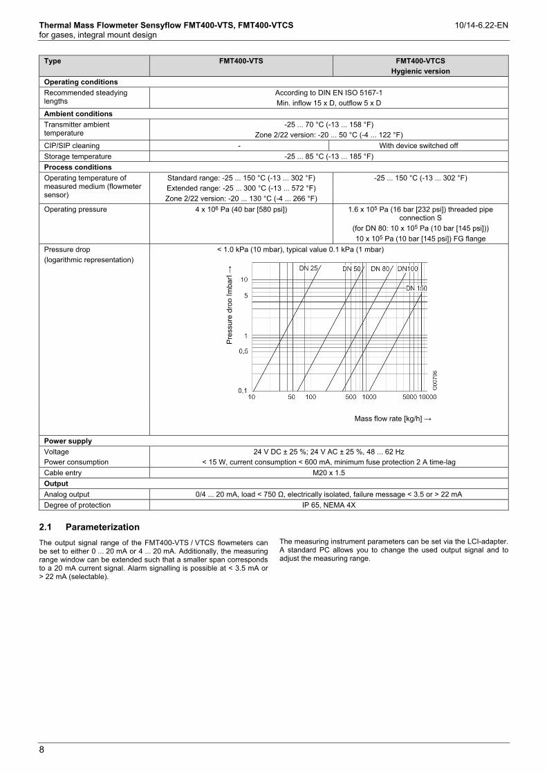
Pressure drop
(logarithmic representation)
< 1.0 kPa (10 mbar), typical value 0.1 kPa (1 mbar)
P
ress
ure
drop
[mba
r] →
Mass flow rate [kg/h] →
Power supply
Voltage
Power consumption
24 V DC ± 25 %; 24 V AC ± 25 %, 48 ... 62 Hz
< 15 W, current consumption < 600 mA, minimum fuse protection 2 A time-lag
Cable entry M20 x 1.5
Output
Analog output 0/4 ... 20 mA, load < 750 Ω, electrically isolated, failure message < 3.5 or > 22 mA
Degree of protection IP 65, NEMA 4X
2.1 Parameterization Change from one to two columns
The output signal range of the FMT400-VTS / VTCS flowmeters can be set to either 0 ... 20 mA or 4 ... 20 mA. Additionally, the measuring range window can be extended such that a smaller span corresponds to a 20 mA current signal. Alarm signalling is possible at < 3.5 mA or > 22 mA (selectable).
The measuring instrument parameters can be set via the LCI-adapter. A standard PC allows you to change the used output signal and to adjust the measuring range.
Change from one to two columns

Thermal Mass Flowmeter Sensyflow FMT400-VTS, FMT400-VTCS 10/14-6.22-EN for gases, integral mount design
9
3 Sensyflow FMT400-VTS, version for process engineering
3.1 Dimensions
Flowmeter sensor Type 1 pipe component
Wafer type
Type 2 pipe component
Measuring section
Weld-on adapter
DN 100 (4") and higher
optional with integrated flow straightener
EN 1092-1 form B1, PN 40
Nominal diameter
L2 h D1 d1 d2 D4 L3 L4
DN 25
B1 = 125
B2 = 80
B3 = Ø115
B4 = 58
L1 = 188
L5 = 450
L7 = 65
(4.92)
(3.15)
(4.53)
(2.28)
(7.40)
(17.72)
(2.56)
269 (10.59) 263 (10.35) - 28.5 (1.12) - 115 (4.53) 600 (23.62) 486 (19.13)
DN 40 94 (3.70) 43.1 (1.70) 88 (3.46) 150 (5.91) 860 (33.86) 731 (28.78)
DN 50 109 (4.29) 54.5 (2.15) 102 (4.02) 165 (6.50) 1000 (39.37) 837 (32.95)
DN 65 129 (5.08) 70.3 (2.77) 122 (4.80) 185 (7.28) 1400 (55.12) 1190 (46.85)
DN 80 144 (5.67) 82.5 (3.25) 138 (5.43) 200 (7.87) 1700 (66.93) 1450 (57.09)
DN 100 170 (6.69) 107.1 (4.22) 162 (6.38) 235 (9.25) 2200 (86.61) 1870 (73.62)
DN 125 196 (7.72) 131.7 (5.19) 188 (7.40) 270 (10.63) 2700 (106.3) 2300 (90.55)
DN 150 226 (8.90) 159.3 (6.27) 218 (8.58) 300 (11.81) 3200 (125.98) 2720 (107.09)
DN 200 293 (11.54) 206.5 (8.13) 285 (11.22) 375 (14.76) 4200 (165.35) 3580 (140.94)
> 350 431 (16.97) 425 (16.73)
> 700 781 (30.75) 775 (30.51)
ASME B 16.5, Cl. 150 (ANSI), Sch 40 S
1“ B1 = 125
B2 = 80
B3 = Ø115
B4 = 58
L1 = 188
L5 = 450
L7 = 65
(4.92)
(3.15)
(4.53)
(2.28)
(7.40)
(17.72)
(2.56)
269 (10.59) 263 (10.35) - 26.6 (1.05) - 108 (4.25) 560 (22.05) 454 (17.87)
1 1/2“ 85 (3.35) 40.9 (1.61) 73 (2.87) 127 (5.00) 864 (34.02) 741 (29.17)
2“ 103 (4.06) 52.6 (2.07) 92 (3.62) 154 (6.06) 1003 (39.49) 846 (33.31)
3“ 35 (5.31) 78.0 (3.07) 127 (5.00) - - -
4“ 173 (6.81) 102.4 (4.03) 157 (6.18) - - -
6“ 221 (8.70) 154.2 (6.07) 216 (8.50) - - -
8“ 278 (10.94) 202.7 (7.98) 270 (10.63) - - -
> 14“ 431 (16.97) 425 (16.73)
> 28“ 781 (30.75) 775 (30.51)
ASME B 16.5, Cl. 300 (ANSI), Sch 40 S
1“ B1 = 125
B2 = 80
B3 = Ø115
B4 = 58
L1 = 188
L5 = 450
L7 = 65
(4.92)
(3.15)
(4.53)
(2.28)
(7.40)
(17.72)
(2.56)
269 (10.59) 263 (10.35) - 26.6 (1.05) - 123.9 (4.88) 560 (22.05) 454 (17.87)
1 1/2“ 94 (3.70) 40.9 (1.61) 73 (2.87) 155.4 (6.12) 864 (34.02) 741 (29.17)
2“ 110 (4.33) 52.6 (2.07) 92 (3.62) 165.1 (6.50) 1003 (39.49) 846 (33.31)
3“ 148 (5.83) 78.0 (3.07) 127 (5.00) - - -
4“ 180 (7.09) 102.4 (4.03) 157 (6.18) - - -
6“ 249 (9.80) 154.2 (6.07) 216 (8.50) - - -
8“ 307 (12.09) 202.7 (7.98) 270 (10.63) - - -
> 14“ 431 (16.97) 425 (16.73)
> 28“ 781 (30.75) 775 (30.51)
Dimensions in mm (inch)

Thermal Mass Flowmeter Sensyflow FMT400-VTS, FMT400-VTCS 10/14-6.22-EN for gases, integral mount design
10
3.2 Installation instructions
3.2.1 Weld-on adapter for Sensyflow FMT400-VTS
← Direction of flow
Fig. 4: Dimensions in mm (inch)
1 Centering pin
2 Sealing ring groove
3 Connection flange DN 25 (1”)
D Outer pipe diameter
Flowmeter sensor length h
in mm (inch)
Outer pipe diameter min. / max.
in mm (inch)
263 (10.35) 100 ... 350 (3.94 ... 13.78)
425 (16.73) > 350 ... 700 (13.78 ... 27.56)
775 (30.51) > 700 ... 1400 (27.56 ... 55.12)1)
1) This maximum pipe diameter specification is only valid when installing the sensor unit centrically in the pipe. For larger diameters or angular ducts a non-centric sensor position is taken into account for calibration.
IMPORTANT (NOTE)
Prior to mounting the weld-on adapters must be shortened to length: L = h - 1/2 Douter.
The distance h between the upper flange edge and the pipe center line must be within a tolerance of ± 2 mm (0.08“).
The right angle to the pipe center line must be observed (max. tolerance ± 2°).
The centering pin of the adapter must be aligned centrically with the pipe center line in flow direction (on outlet run side, downstream of the measuring point).
Thermal Mass Flowmeter Sensyflow FMT400-VTS, FMT400-VTCS 10/14-6.22-EN for gases, integral mount design
11
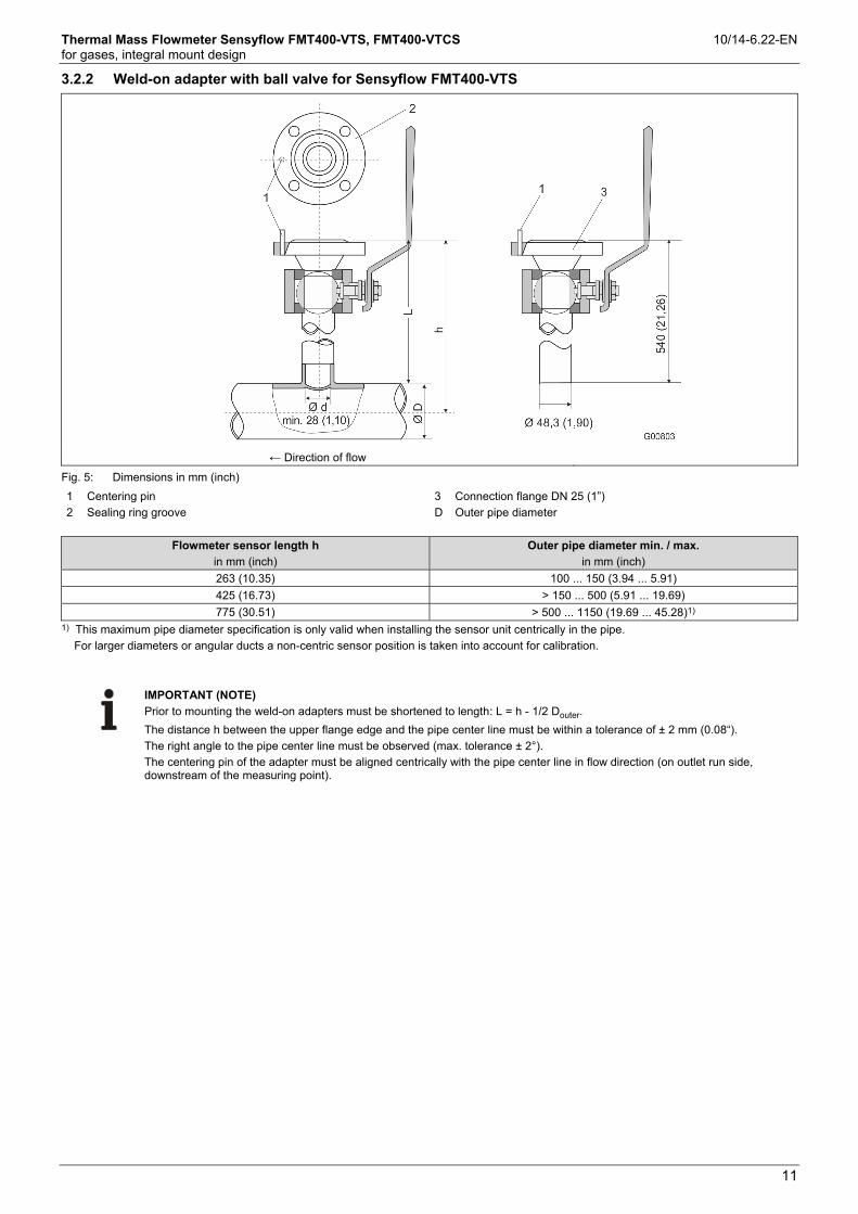
3.2.2 Weld-on adapter with ball valve for Sensyflow FMT400-VTS
← Direction of flow
Fig. 5: Dimensions in mm (inch)
1 Centering pin
2 Sealing ring groove
3 Connection flange DN 25 (1”)
D Outer pipe diameter
Flowmeter sensor length h
in mm (inch)
Outer pipe diameter min. / max.
in mm (inch)
263 (10.35) 100 ... 150 (3.94 ... 5.91)
425 (16.73) > 150 ... 500 (5.91 ... 19.69)
775 (30.51) > 500 ... 1150 (19.69 ... 45.28)1) 1) This maximum pipe diameter specification is only valid when installing the sensor unit centrically in the pipe.
For larger diameters or angular ducts a non-centric sensor position is taken into account for calibration.
IMPORTANT (NOTE)
Prior to mounting the weld-on adapters must be shortened to length: L = h - 1/2 Douter.
The distance h between the upper flange edge and the pipe center line must be within a tolerance of ± 2 mm (0.08“).
The right angle to the pipe center line must be observed (max. tolerance ± 2°).
The centering pin of the adapter must be aligned centrically with the pipe center line in flow direction (on outlet run side, downstream of the measuring point).

Thermal Mass Flowmeter Sensyflow FMT400-VTS, FMT400-VTCS 10/14-6.22-EN for gases, integral mount design
12
3.2.3 Integrated hot tap fitting for Sensyflow FMT400-VTS
Water flange version – sensor unit in exchange position
Weld-in version – sensor unit in measuring position
Fig. 6: Dimensions in mm (inch)
1 Covers for DN 25 flange
2 Spigot nur
3 Bottom edge of spigot nut
4 Display of sensor unit position, 50 mm (1,97“) stroke
5 Sealing ring
6 Sensor elements
Flowmeter sensor length h
Water flange version Weld-in version
h = 263 mm (10.35“)
for DN 50, DN 65 and DN 80 / 2“, 3“
h = 425 mm (16.73“)
for DN 100, DN 125, DN 150 and DN 200 / 4“, 6“, 8“
h = always 425 mm (16.73“)

Thermal Mass Flowmeter Sensyflow FMT400-VTS, FMT400-VTCS 10/14-6.22-EN for gases, integral mount design
13
Change from one to two columns
The integrated hot tap fitting is used instead of the pipe component and weld-on adapter assembly described above if the flowmeter sensor must be exchangeable during operation with virtually no gas escaping from the system.
Fig. 7: Maximum pressure/temperature values for the integrated hot tap fitting
It is recommended to use the hot tap fitting for measurements in main conduits (e.g. compressed air systems) or for measuring points which otherwise require rinsing prior to removing the flowmeter sensor. As a rule, hot tap fittings should be preferred for all systems where, otherwise, the entire system or parts of it must be switched off to replace a flowmeter sensor.
Handling:
The flowmeter sensor is screwed to the hot tap fitting through the DN 25 flange. Then the cover is put on. The sensor unit is set from the exchange position to the measuring position by turning the spigot nut. The bottom edge of the spigot nut indicates the current sensor unit position (see Detail A, sensor unit is in exchange position). Only when the measuring position 50 – OPEN - MESSEN (lower stop of the spigot nut) is reached, the sensor elements are placed exactly in the center of the pipe and exact measurement is ensured.
IMPORTANT (NOTE)
For integrated hot tap fitting in wafer flange design DN 65, use connection flange PN16 with 4 screw holes on the process side. Wafer flange versions 2 ... 8" only for con-nection flange ASME B16.5 Cl.150.
Change from one to two columns
Thermal Mass Flowmeter Sensyflow FMT400-VTS, FMT400-VTCS 10/14-6.22-EN for gases, integral mount design
14
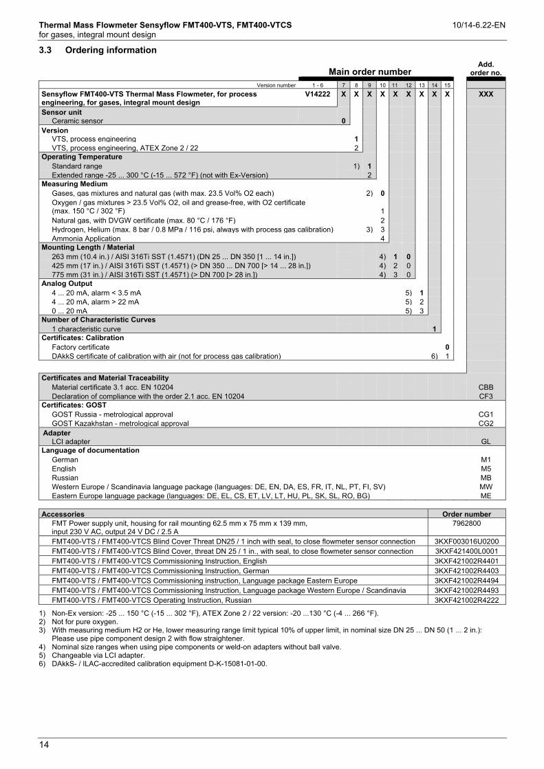
3.3 Ordering information
Main order number
Add. order no.
Version number 1 - 6 7 8 9 10 11 12 13 14 15
Sensyflow FMT400-VTS Thermal Mass Flowmeter, for process engineering, for gases, integral mount design
V14222 X X X X X X X X X XXX
Sensor unit Ceramic sensor 0
Version VTS, process engineering 1 VTS, process engineering, ATEX Zone 2 / 22 2
Operating Temperature Standard range 1) 1 Extended range -25 ... 300 °C (-15 ... 572 °F) (not with Ex-Version) 2
Measuring Medium Gases, gas mixtures and natural gas (with max. 23.5 Vol% O2 each) 2) 0 Oxygen / gas mixtures > 23.5 Vol% O2, oil and grease-free, with O2 certificate (max. 150 °C / 302 °F) 1
Natural gas, with DVGW certificate (max. 80 °C / 176 °F) 2 Hydrogen, Helium (max. 8 bar / 0.8 MPa / 116 psi, always with process gas calibration) 3) 3 Ammonia Application 4
Mounting Length / Material 263 mm (10.4 in.) / AISI 316Ti SST (1.4571) (DN 25 ... DN 350 [1 ... 14 in.]) 4) 1 0 425 mm (17 in.) / AISI 316Ti SST (1.4571) (> DN 350 ... DN 700 [> 14 ... 28 in.]) 4) 2 0 775 mm (31 in.) / AISI 316Ti SST (1.4571) (> DN 700 [> 28 in.]) 4) 3 0
Analog Output 4 ... 20 mA, alarm < 3.5 mA 5) 1 4 ... 20 mA, alarm > 22 mA 5) 2 0 ... 20 mA 5) 3
Number of Characteristic Curves 1 characteristic curve 1
Certificates: Calibration Factory certificate 0 DAkkS certificate of calibration with air (not for process gas calibration) 6) 1
Certificates and Material Traceability Material certificate 3.1 acc. EN 10204 CBB Declaration of compliance with the order 2.1 acc. EN 10204 CF3
Certificates: GOST GOST Russia - metrological approval CG1 GOST Kazakhstan - metrological approval CG2
Adapter LCI adapter GL
Language of documentation German M1 English M5 Russian MB Western Europe / Scandinavia language package (languages: DE, EN, DA, ES, FR, IT, NL, PT, FI, SV) MW Eastern Europe language package (languages: DE, EL, CS, ET, LV, LT, HU, PL, SK, SL, RO, BG) ME
Accessories Order number
FMT Power supply unit, housing for rail mounting 62.5 mm x 75 mm x 139 mm, input 230 V AC, output 24 V DC / 2.5 A
7962800
FMT400-VTS / FMT400-VTCS Blind Cover Threat DN25 / 1 inch with seal, to close flowmeter sensor connection 3KXF003016U0200 FMT400-VTS / FMT400-VTCS Blind Cover, threat DN 25 / 1 in., with seal, to close flowmeter sensor connection 3KXF421400L0001 FMT400-VTS / FMT400-VTCS Commissioning Instruction, English 3KXF421002R4401 FMT400-VTS / FMT400-VTCS Commissioning Instruction, German 3KXF421002R4403 FMT400-VTS / FMT400-VTCS Commissioning instruction, Language package Eastern Europe 3KXF421002R4494 FMT400-VTS / FMT400-VTCS Commissioning Instruction, Language package Western Europe / Scandinavia 3KXF421002R4493 FMT400-VTS / FMT400-VTCS Operating Instruction, Russian 3KXF421002R4222
1) Non-Ex version: -25 ... 150 °C (-15 ... 302 °F), ATEX Zone 2 / 22 version: -20 ...130 °C (-4 ... 266 °F). 2) Not for pure oxygen. 3) With measuring medium H2 or He, lower measuring range limit typical 10% of upper limit, in nominal size DN 25 ... DN 50 (1 ... 2 in.):
Please use pipe component design 2 with flow straightener. 4) Nominal size ranges when using pipe components or weld-on adapters without ball valve. 5) Changeable via LCI adapter. 6) DAkkS- / ILAC-accredited calibration equipment D-K-15081-01-00.

Thermal Mass Flowmeter Sensyflow FMT400-VTS, FMT400-VTCS 10/14-6.22-EN for gases, integral mount design
15
Main order number
Add. order no.
Version number 1 - 6 7-9 10 11 12 13 14 15
FMT081 pipe component / weld-on adapter, for Sensyflow
FMT500-IG and FMT400-VTS FMT081 XXX X X X X X X XXX
Mounting Length of the Sensor 263 mm (10.4 in.) 263 425 mm (17 in.) 425 775 mm (31 in.) 775
Measuring Medium Gases, gas mixtures, and natural gas (each max. 23.5 vol% O2) A Oxygen / gas mixtures > 23.5 Vol% O2, oil and grease-free, with O2 certificate (max. 150 °C / 302 °F) B
Natural gas, with DVGW certificate (max. 80 °C / 176 °F) C Hydrogen, Helium 1) D
Design Pipe component 1 in wafer flange version 1 Pipe component design 2 as partial measuring section 2 Pipe component design 2 as partial measuring section with integrated flow straigtheners
3
Weld-on adapter 2) 4 Other 9
Nominal Diameter Selection for weld-on adapter Y DN 25 (1 in.) 3) A DN 40 (1-1/2 in.) 4) C DN 50 (2 in.) D DN 65 (2-1/2 in.) 5) E DN 80 (3 in.) 6) F DN 100 (4 in.) 6) G DN 125 (5 in.) 6) H DN 150 (6 in.) 6) J DN 200 (8 in.) 6) L Other 7) Z
Flange Style and Pressure Rating Selection for weld-on adapter 0 DIN PN 40, nominal pressure 40 bar (4 MPa / 580 psi) 1 ANSI / ASME CL 150, Schedule 40 S 2 ANSI / ASME CL 300, Schedule 40 S 4) 3 Other 9
Process Connection for Flowmeter Sensor Standard Sensyflow flange with centering pin 8) A With ball valve, max. 150 °C (302 °F) and 16 bar (1.6 MPa / 232 psi) 9) G
With integrated hot tap fitting for max. DN 125 (5 in.). Allows gas-tight flowmeter sensor removal / insertion up to 16 bar (1.6 MPa / 232 psi) or 200 °C (392 °F). For DN 65, use connection flanges PN 16 with 4 screw holes (For pipe component DN 50 ... DN 80, apply Sensor Length h = 263 mm, from DN 100 and for weld-on adapter, apply Sensor Length h = 425 mm)
10) H
With integrated hot tap fitting above DN 125 (5 in.) to max. DN 200 (8 in.) / DN 300 (12 in.) with weld-on adapter. Allows gas-tight flowmeter sensor removal / insertion up to 16 bar (1.6 MPa / 232 psi) or 200 °C (392 °F) (Please apply the correct sensor length)
11) J
Material Stainless steel AISI 316Ti (1.4571) 3 Carbon steel S 235 (1.0037) 12) 1 Plastics PE-HD (Polyethylene high-density) 12) 7
Blind Flange
DN 25 blind flange to close flowmeter sensor connection, material stainless steel AISI 316Ti (1.4571) F3 Certificates and Material Traceability
Material certificate 3.1 acc. EN 10204 CBB Declaration of compliance with the order 2.1 acc. EN 10204 CF3
Footnotes see next page

Thermal Mass Flowmeter Sensyflow FMT400-VTS, FMT400-VTCS 10/14-6.22-EN for gases, integral mount design
16
1) Max. 8 bar / 0.8 MPa / 116 psi. With DN 25 ... DN 50 (1 ... 2 in.): Please use pipe component 2 with flow straightener. 2) From DN 100 (4 in.). 3) Not available with pipe component 1 in wafer flange version. 4) Not available with hot-tap-fitting. 5) Not available with flange style ANSI / ASME. 6) Not available with pipe component 2 in combination with flange style ANSI / ASME. 7) Please specify exact inner pipe diameter. 8) Correct sensor length: For pipe component 1 and 2 without ball valve / hot tap fitting: h = 263 mm. For weld-on adapter and pipe diameter
up to 350 mm: h = 263 mm, up to 700 mm: h = 425 mm, > 700 mm: h = 775 mm 9) Not available with DVGW certificate. Correct sensor length: For pipe component DN 50 ... DN 100: h = 263 mm, from DN 125: h = 425 mm.
For weld-on adapter up to 150 mm: h = 263 mm, up to 500 mm: h = 425 mm, > 500 mm: h = 775 mm 10) Not available with DVGW certificate. Correct sensor length: For pipe component DN 50 ... DN 80: h = 263 mm, for pipe component from DN
100 and weld-on adapter: h = 425 mm. 11) Not available with DVGW certificate. Please apply the correct sensor length. 12) Only for weld-on adapter without ball-valve. Only without certificates.
3.4 Additional ordering information for calibration
FMT400-VTS, FMT400-VTCS Gas component 1 Vol. % (clear text) Gas component 2 Vol. % (clear text) Gas component 3 Vol. % (clear text) Gas component 4 Vol. % (clear text) Gas component 5 Vol. % (clear text) Gas component 6 Vol. % (clear text) Gas component 7 Vol. % (clear text) Gas component 8 Vol. % (clear text) Gas component 9 Vol. % (clear text) Gas component 10 Vol. % (clear text) Sum 100 % Operating temperature (clear text) Operating pressure (clear text) Nominal diameter, Pipe inner diameter (mm) (clear text) Measuring range (clear text) Unit (clear text) Standard state (e.g. 0 °C, 1013 mbar) (clear text) Adjusted measuring range (clear text)

Thermal Mass Flowmeter Sensyflow FMT400-VTS, FMT400-VTCS 10/14-6.22-EN for gases, integral mount design
17
4 Sensyflow FMT400-VTCS, hygienic version
4.1 Dimensions
Pipe fitting S according to DIN 11851
Pipe component with pipe fitting S according to DIN 11851 Flowmeter sensor
Direction of flow →
Direction of flow →
Fig. 8: Nominal pressure PN16 for DN 25, DN 40, DN50; PN10 for DN 80
1 Centre of pipe component
DN A L L1 L2 Ø D G
25 (1“) 196 (7.72) 182 (7.17) 140 (5.51) 42 (1.65) 28 x 1 (1.10 x 0.04) Rd52 x 1/6“
40 (1.5“) 284 (11.18) 270 (10.63) 205 (8.07) 65 (2.56) 40 x 1 (1.57 x 0.04) Rd62 x 1/6“
50 (2“) 344 (13.54) 330 (12.99) 265 (10.43 65 (2.56) 52 x 1 (2.04 x 0.04) Rd78 x 1/6“
80 (3“) 526 (20.71) 510 (20.08) 425 (16.73) 85 (3.35) 85 x 2 (3.35 x 0.08) Rd110 x 1/4“
Dimensions in mm (inch)
Thermal Mass Flowmeter Sensyflow FMT400-VTS, FMT400-VTCS 10/14-6.22-EN for gases, integral mount design
18
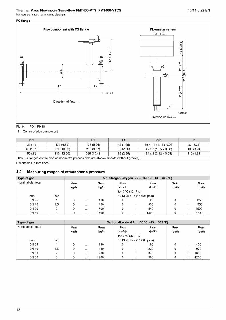
FG flange
Pipe component with FG flange Flowmeter sensor
Direction of flow →
Direction of flow →
Fig. 9: FG1, PN10
1 Centre of pipe component
DN L L1 L2 Ø D F
25 (1“) 175 (6.89) 133 (5.24) 42 (1.65) 29 x 1.5 (1.14 x 0.06) 83 (3.27)
40 (1.5“) 270 (10.63) 205 (8.07) 65 (2.56) 42 x 2 (1.65 x 0.08) 100 (3.94)
50 (2“) 330 (12.99) 265 (10.43 65 (2.56) 54 x 2 (2.12 x 0.08) 110 (4.33)
The FG flanges on the pipe component’s process side are always smooth (without groove).
Dimensions in mm (inch)
4.2 Measuring ranges at atmospheric pressure
Type of gas Air, nitrogen, oxygen -25 ... 150 °C (-13 ... 302 °F)
Nominal diameter qmin
kg/h
qmax
kg/h
qmin
Nm3/h
qmax
Nm3/h
qmin
lbs/h
qmax
lbs/h
mm
inch
for 0 °C (32 °F) /
1013.25 hPa (14.696 psia)
DN 25
DN 40
DN 50
DN 80
1
1.5
2
3
0
0
0
0
...
...
...
...
160
430
700
1700
0
0
0
0
...
...
...
...
120
330
540
1300
0
0
0
0
...
...
...
...
350
950
1500
3700
Type of gas Carbon dioxide -25 ... 150 °C (-13 ... 302 °F)
Nominal diameter qmin
kg/h
qmax
kg/h
qmin
Nm3/h
qmax
Nm3/h
qmin
lbs/h
qmax
lbs/h
mm
inch
for 0 °C (32 °F) /
1013.25 hPa (14.696 psia)
DN 25
DN 40
DN 50
DN 80
1
1.5
2
3
0
0
0
0
...
...
...
...
180
440
730
1900
0
0
0
0
...
...
...
...
90
220
370
900
0
0
0
0
...
...
...
...
400
970
1600
4200
Thermal Mass Flowmeter Sensyflow FMT400-VTS, FMT400-VTCS 10/14-6.22-EN for gases, integral mount design
19
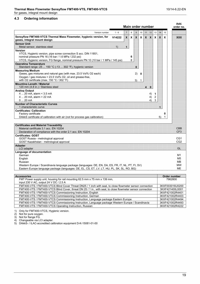
4.3 Ordering information
Main order number
Add. order no.
Version number 1 - 6 7 8 9 10 11 12 13 14 15
Sensyflow FMT400-VTCS Thermal Mass Flowmeter, hygienic version, for gases, integral mount design
V14222 X X X X X X X X X XXX
Sensor Unit Metal sensor, stainless steel 1) 1
Version VTCS, Hygienic version, pipe screw connection S acc. DIN 11851, nominal pressure PN 16 (16 bar / 1.6 MPa / 232 psi)
6
VTCS, Hygienic version, FG flange, nominal pressure PN 10 (10 bar / 1 MPa / 145 psi) 8
Operating Temperature Standard range -25 ... 150 °C (-13 ... 302 °F), hygienic version 0
Measuring Medium Gases, gas mixtures and natural gas (with max. 23.5 Vol% O2 each) 2) 0 Oxygen / gas mixtures > 23.5 Vol% O2, oil and grease-free, with O2 certificate (max. 150 °C / 302 °F)
3) 1
Mounting Length / Material 120 mm (4.8 in.) / Stainless steel 4 0
Analog Output 4 ... 20 mA, alarm < 3.5 mA 4) 1 4 ... 20 mA, alarm > 22 mA 4) 2 0 ... 20 mA 4) 3
Number of Characteristic Curves 1 characteristic curve 1
Certificates: Calibration Factory certificate 0 DAkkS certificate of calibration with air (not for process gas calibration) 5) 1
Certificates and Material Traceability Material certificate 3.1 acc. EN 10204 CBB Declaration of compliance with the order 2.1 acc. EN 10204 CF3
Certificates: GOST GOST Russia - metrological approval CG1 GOST Kazakhstan - metrological approval CG2
Adapter LCI adapter GL
Language of documentation German M1 English M5 Russian MB Western Europe / Scandinavia language package (languages: DE, EN, DA, ES, FR, IT, NL, PT, FI, SV) MW Eastern Europe language package (languages: DE, EL, CS, ET, LV, LT, HU, PL, SK, SL, RO, BG) ME
Accessories Order number FMT Power supply unit, housing for rail mounting 62.5 mm x 75 mm x 139 mm, input 230 V AC, output 24 V DC / 2.5 A
7962800
FMT400-VTS / FMT400-VTCS Blind Cover Threat DN25 / 1 inch with seal, to close flowmeter sensor connection 3KXF003016U0200 FMT400-VTS / FMT400-VTCS Blind Cover, threat DN 25 / 1 in., with seal, to close flowmeter sensor connection 3KXF421400L0001 FMT400-VTS / FMT400-VTCS Commissioning Instruction, English 3KXF421002R4401 FMT400-VTS / FMT400-VTCS Commissioning Instruction, German 3KXF421002R4403 FMT400-VTS / FMT400-VTCS Commissioning Instruction, Language package Eastern Europe 3KXF421002R4494 FMT400-VTS / FMT400-VTCS Commissioning Instruction, Language package Western Europe / Scandinavia 3KXF421002R4493 FMT400-VTS / FMT400-VTCS Operating Instruction, Russian 3KXF421002R4222
1) Only for FMT400-VTCS, Hygienic version. 2) Not for pure oxygen. 3) Not for flange FG. 4) Changeable via LCI adapter. 5) DAkkS- / ILAC-accredited calibration equipment D-K-15081-01-00

Thermal Mass Flowmeter Sensyflow FMT400-VTS, FMT400-VTCS 10/14-6.22-EN for gases, integral mount design
20
Main order number
Add. order no.
Version number 1 - 6 7-9 10 11 12 13 14 15
FMT082 pipe component, for Sensyflow FMT400-VTCS FMT082 XXX X X X X X X XXX
Mounting Length of the Sensor 120 mm (4.8 in.) 120
Measuring Medium Gases, gas mixtures and natural gas (each max. 23.5 Vol% O2) A Oxygen / gas mixtures > 23.5 Vol% O2, oil and grease-free, with O2 certificate (max. 150 °C / 302 °F) B
Design Pipe component for Sensyflow FMT400-VTCS 0
Nominal diameter DN 25 (1 in.) A DN 40 (1-1/2 in.) C DN 50 (2 in.) D DN 80 (3 in.) F
Flange Style and Pressure Rating Pipe screw connection S acc. DIN 11851, nominal pressure PN 16 (16 bar / 1.6 MPa / 232 psi) 6 FG flange, nominal pressure PN 10 (10 bar / 1 MPa / 145 psi) 1) 8
Process Connection for Flowmeter Sensor Standard Sensyflow flange with centering pin A
Material Stainless steel AISI 304 (1.4301), only with pipe screw connection S / nominal pressure PN 16 4 Stainless steel AISI 316L (1.4404), only with FG flange / nominal pressure PN 10 5
Certificates and Material Traceability Material certificate 3.1 acc. EN 10204 CBB Declaration of compliance with the order 2.1 acc. EN 10204 CF3
1) Not available with oxygen measurement
4.4 Additional ordering information for calibration
FMT400-VTS, FMT400-VTCS Gas component 1 Vol. % (clear text) Gas component 2 Vol. % (clear text) Gas component 3 Vol. % (clear text) Gas component 4 Vol. % (clear text) Gas component 5 Vol. % (clear text) Gas component 6 Vol. % (clear text) Gas component 7 Vol. % (clear text) Gas component 8 Vol. % (clear text) Gas component 9 Vol. % (clear text) Gas component 10 Vol. % (clear text) Sum 100 % Operating temperature (clear text) Operating pressure (clear text) Nominal diameter, Pipe inner diameter (mm) (clear text) Measuring range (clear text) Unit (clear text) Standard state (e.g. 0 °C, 1013 mbar) (clear text) Adjusted measuring range (clear text)

Thermal Mass Flowmeter Sensyflow FMT400-VTS, FMT400-VTCS 10/14-6.22-EN for gases, integral mount design
21
5 Electrical connections
Fig. 10
1 Socket for LCI adapter
2 Analog output 0/4 ... 20 mA (electrically isolated)
3 Power supply 24 V AC/DC
4 Terminals
5 Ground
6 Cable entry

Thermal Mass Flowmeter Sensyflow FMT400-VTS, FMT400-VTCS 10/14-6.22-EN for gases, integral mount design
22
6 Recommended steadying lengths according to DIN EN ISO 5167-1
Expansion
X = 15
Reducer
X = 15
90° elbow
X = 20
Two 90° elbow in one level
X = 25
Two 90°elbow in two levels
X = 40
Valve / slide
X = 50
Change from one to two columns
To achieve the stated measuring accuracy, the steadying lengths seen above must be provided. For combinations of inlet run dist-urbances, e. g. valve and reducer, you must always consider the longer inlet run length. In confined spaces at the mounting location the outlet run length can be shortened to 3 x D. The reduction of the minimum inlet run length, however, will impact on the achievable accuracy.
High repeatability of the measuring value is still provided. Under certain circumstances, special calibration can be performed for insuf-ficient steadying lengths. For this purpose and in individual cases consulting is necessary.
For gases with extremely low density (hydrogen, helium) the stead-ying lengths must be doubled.
Change from one to two columns

Thermal Mass Flowmeter Sensyflow FMT400-VTS, FMT400-VTCS 10/14-6.22-EN for gases, integral mount design
23
7 Questionnaire
QuestionnaireThermal Mass Flowmeter
Sensyflow FMT
Customer address:
Company:
Zip code and location: Date:
Cust. no.: Telephone:
Contact person: E-mail:
Media data for gaseous, pure media:
Description of media Mixed gas, gas composition in vol.%1)
Type of gas (no mixtures): Component 1/name/vol.%:
Operating pressure (bar abs.) Component 2/name/vol.%:
Min./norm./max., approx. Component 3/name/vol.%:
Operating temperature (°C) Component 4/name/vol.%:
Min./norm./max., approx. Component 5/name/vol.%:
Flowrate 2) Min.: Norm.: Max.: Pipeline/pipe component3)
Flow unit: Standard volume Mass flow units DN/PN:Nm3/h kg/h ANSI/lbs
Nm3/min kg/min Diameter [mm]Nl/min g/min Inside diameter specified in mm
SCFM t/h Wafer flange form 1Other Other Partial meas. section form 2
°Standard condition, e.g., 0°C/1,013 mbar or Weld-on adapterOther
Required device designs: Design:
FMT500-IG FMT700-P4) Integral mount designFMT400-VTS FMT200-ECO2 Remote design with
FMT400-VTCS FMT200-D Cable length 5 m Cable length 15 m
Output signal: Ex protection class: Cable length 25 m
0/4...20 mA None Zone 2/22 24 V 4...20 mA/HART ATEX Zone 1/21 GOST 110 V
PROFIBUS DP-V1 ATEX Zone 0/21 FM/CSA 230 V
Comments:
2) Calibration is performed at the max. possible flow in the nominal size specified.
3) Please observe/determine the minimum inflow and outflow sections.
4) Output signal: 0...10 V as standard
1) Please specify the composition of mixed gases (e.g., North Sea natural gas: 1) CH4 90%, 2) C2H6 5%, 3) N2 3%, 4) C3H8, 1%, 5) CO2 1%).
Note: An order can only be confirmed and a delivery date specified once full technical clearance has been obtained.

— ABB Limited Measurement & Analytics Howard Road, St. Neots Cambridgeshire, PE19 8EU UK Tel: +44 (0)870 600 6122 Fax: +44 (0)1480 213 339 Email: [email protected] ABB Automation Products GmbH Measurement & Analytics Schillerstr. 72 32425 Minden Germany Tel: +49 571 830-0 Fax: +49 571 830-1806 abb.com/flow
ABB Inc. Measurement & Analytics 125 E. County Line Road Warminster, PA 18974 USA Tel: +1 215 674 6000 Fax: +1 215 674 7183
10/1
4-6.
22-E
N R
ev. H
0
3.20
19
— We reserve the right to make technical changes or modify the contents of this document without prior notice. With regard to purchase orders, the agreed particulars shall prevail. ABB does not accept any responsibility whatsoever for potential errors or possible lack of information in this document. We reserve all rights in this document and in the subject matter and illustrations contained therein. Any reproduction, disclosure to third parties or utilization of its contents – in whole or in parts – is forbidden without prior written consent of ABB. © ABB 2019 3KXF421002R1001
— ABB MEASUREMENT & ANALYTICS | DATA SHEET
Sensyflow FMT400-VTS, FMT400-VTCS Thermal Mass Flowmeter