thermal fracture as a framework for quasi-static crack
TRANSCRIPT

Int J Fract (2009) 158:1–14DOI 10.1007/s10704-009-9361-4
ORIGINAL PAPER
Thermal fracture as a framework for quasi-static crackpropagation
F. Corson · M. Adda-Bedia · H. Henry ·E. Katzav
Received: 14 January 2008 / Accepted: 11 May 2009 / Published online: 6 June 2009© Springer Science+Business Media B.V. 2009
Abstract We address analytically and numericallytheproblemofcrackpathprediction in themodelsystemof a crack propagating under thermal loading. We showthat one can explain the instability from a straight to awavy crack propagation by using only the principle oflocal symmetry and the Griffith criterion. We then arguethat the calculations of the stress intensity factors can becombinedwith thestandardcrackpropagationcriteria toobtain the evolution equation for the crack tip within anyloadingconfiguration.Thetheoreticalresultsof thether-malcrackproblemagreewith thenumerical simulationswe performed using a phase field model. Moreover, itturns out that the phase-field model allows to clarify thenature of the transition between straight and oscillatorycracks which is shown to be supercritical.
Keywords Thermal crack · Principle of localsymmetry · Phase field model · Crack path prediction
1 Introduction
Crack path prediction is one of the main challenges inthe field of fracture mechanics. The reason is simple—a
F. Corson · M. Adda-Bedia · E. Katzav (B)Laboratoire de Physique Statistique, ENS, Paris VI,Paris VII, CNRS, 24 rue Lhomond, 75005 Paris, Francee-mail: [email protected]
H. HenryLaboratoire de Physique de la Matière condensée, CNRSUMR7643, Ecole Polytechnique, 91128 Palaiseau Cedex, France
satisfactory equation of motion of a crack tip is asso-ciated with a fundamental understanding of materialseparation mechanisms (Freund 1990; Broberg 1999;Fineberg and Marder 1999; Adda-Bedia et al. 1999;Leblond 2003). From a more general point of viewand alongside its importance in many applications, thedetermination of crack propagation laws is necessary todescribe the fracture phenomenon as a pattern forma-tion process induced by mechanical stresses. Withinthe framework of Linear Elastic Fracture Mechanics(LEFM), the propagation of a crack is mainly governedby the singular behavior of the stress field in the vicinityof its tip (Freund 1990; Broberg 1999; Leblond 2003).For a two-dimensional quasi-static crack, which is themain purpose of the present work, this behavior is givenby
σi j (r, φ) = KI√2πr
�Ii j (φ) + KII√
2πr�II
i j (φ) + O(r0),
(1)
where �Ii j (φ) and �II
i j (φ) are universal functionsdescribing the angular variation of the stress field, andKI and KII are the stress intensity factors (SIFs). Theevolution of the crack tip is governed by the Griffithenergy criterion (Griffith 1920; Freund 1990; Broberg1999; Leblond 2003), which states that the intensity ofthe loading necessary to induce propagation is givenby G = �, where G is the energy release rate and �
is the fracture energy of the material, that is the energyneeded to create new free surfaces. This criterion canbe rewritten using the stress intensity factor, in which
123

2 F. Corson et al.
case it is referred to as the Irwin criterion (1957)
KI = KIc ≡ √2µ�, (2)
where KIc is the toughness of the material and µ isthe shear modulus. The Griffith criterion was originallyformulated for quasi-static crack propagation (Griffith1920), and later generalized to rapidly moving cracks(Freund 1990). While this criterion is very useful inpredicting crack initiation, it cannot predict the direc-tion of the crack tip, and therefore in most cases it isnot sufficient to determine the actual path of the crack.In order to achieve this, several suggestions have beenmade. Among them, the Principle of Local Symme-try (PLS) states that the crack advances in such a waythat in-plane shear stress vanishes in the vicinity of thecrack tip, or explicitly
KII = 0, (3)
This rule was proposed for in-plane quasi-static cracks(Gol’dstein and Salganik 1974; Leblond 1989), andthen generalized to rapidly moving cracks (Adda-Bediaet al. 1999). Note that from a historical point of view, thefirst criterion for crack path selection, based on symme-try arguments similar to the PLS, was first formulatedfor antiplane (mode III) crack propagation (Barenblattand Cherepanov 1961). Recently, the dynamics of arough crack in two dimensions has been successfullydescribed by an equation of motion derived using thePLS (Katzav et al. 2007a). Another suggestion, basedon symmetry arguments, and which recovers the princi-ple of local symmetry in a certain limit, was proposedby Hodgdon and Sethna (1993), who formulated anequation of motion of the crack tip. However, this for-mulation introduces additional length scales, which arenot known a priori. A different approach, known as themaximum energy release rate criterion (Erdogan andSih 1963) states that the crack advances in a directionthat maximizes its energy release rate. Interestingly,even though this approach is quite different from thePLS, it produces very similar results to those obtainedusing the PLS to such an extent that they were even con-jectured to coincide (Bilby and Cardew 1975). How-ever, as shown in Amestoy and Leblond (1992) forkinked cracks and in Katzav et al. (2007b) for branchedcracks, the results are not exactly the same and a cleardistinction can be made between the two. Actually,it has been shown that the PLS is the only self-con-sistent criterion (Leblond 1989, 2003). A theoreticalchallenge is to explain the current rich crack path phe-nomenology, including the various known instabilities,
Fig. 1 The experimental setup. A glass plate of width 2b ismoved slowly at a constant velocity v from an oven maintainedat temperature T0 + �T to a cold bath of fixed temperature T0.The crack tip is steady in the laboratory frame (moving in theplate frame) and its position with respect to the cold bath (bl) iscontrolled by the temperature field
using a pure LEFM approach combined with theGriffith criterion and the PLS. This has been recentlyargued for roughening instabilities of cracks in (Katzavet al. 2007a), as well as for the branching instability in(Katzav et al. 2007b) and here we wish to contributefurther to this effort.
Trying to address the problem of crack path predic-tion from the experimental side, the thermal crack prob-lem has attracted a lot of attention. The propagation ofcracks induced by thermal gradients has been widelystudied (Ronsin et al. 1995; Ronsin 1996; Yuse andSano 1997; Ronsin and Perrin 1998; Yang and Ravi-Chandar 2001; Deegan et al. 2003; Yoneyama et al.2006, 2008; Sakaue et al. 2008) since the work of Yuseand Sano (1993). In a typical experiment, a glass stripwith a notch at its end is pulled at a constant velocityfrom an oven into a cold bath (see Fig. 1). The controlparameters in this experiment are mainly the width ofthe strip, the temperature gradient between the ovenand the cold bath, and the pulling velocity. If the veloc-ity is small enough, a crack does not propagate. Abovea first critical velocity, the crack starts propagating fol-lowing a straight centered path, and above a second crit-ical velocity, the crack begins to oscillate with a welldefined wavelength. However, the nature of the transi-tion from straight to wavy path is not fully understood.For example, the experimental results (Ronsin 1996;Yuse and Sano 1997) are not sufficient to determinewhether the bifurcation is super-critical or sub-critical(also referred to as continuous or discontinuous tran-sition).1 At higher pulling velocities, irregular oscilla-
1 In Yuse and Sano (1997), the bifurcation is claimed to be super-critical. Nonetheless, data points close to threshold are not accu-rate enough to rule out any other hypothesis (see Fig. 5 on page372 in Yuse and Sano 1997). Results presented in Ronsin (1996)suffer from the same lack of data points close to threshold.
123

Thermal fracture as a framework for quasi-static crack propagation 3
tions and branching are observed. Interestingly, theseare very reproducible regimes, which makes the ther-mal crack an ideal model experiment as it allows tostudy the slow propagation of cracks under well con-trolled conditions.
In an attempt to provide a theoretical explanation,Marder (1994) successfully determined the propaga-tion threshold by calculating KI for a straight crackpropagating at the center of the plate. He also pro-posed a description of the oscillatory instability usingthe stability criterion derived by Cotterell and Rice(1980) for a crack in an infinite plate (the celebratedT -criterion), but that implied the improbable require-ment that the fracture energy should depend stronglyon the velocity. Eventually, this result was found to beincompatible with the experimental evidence (Ronsinet al. 1995), and serves as a classical example for theviolation of the T -criterion. Sasa et al. (1994) attemptedto predict the threshold of the oscillatory instability andits wavelength by using the PLS under the infinite-plateapproximation. Although they gave a reasonable quali-tative description, their results deviated systematicallyfrom the experimental measurements. The next stepwas taken by Adda-Bedia and Pomeau (1995), whocalculated KII directly for a sinusoidal perturbation ina finite strip, in the configuration where the crack tipis at the center of the strip. However, in order to pre-dict the oscillatory instability they resorted to an addi-tional criterion, namely that the stability with respectto this perturbation depends on the sign of KII. Morerecently, Bouchbinder et al. (2003) wrote an amplitudeequation for a sinusoidal perturbation using the prop-agation criterion of Hodgdon and Sethna (1993). Oneshould note that all these approaches rely on additionalcriteria when determining the instability threshold andcannot do so using only the classical principles of crackpropagation. In addition, theoretical results, except anattempt in Bouchbinder et al. (2003), are mostly limitedto the study of the linear stability of a straight crack orto the study of transient regimes. This situation calls fora reexamination of the thermal crack problem in orderto explain it using solid arguments.
In this work, we begin with the study of quasistaticcracks in a quenched glass plate using a phase-fieldapproach. Phase field models were originally intro-duced by Caginalp and Fife (1986); Collins and Levine(1986) to describe the propagation of solidificationfronts. Extensions of this work allowed quantitativemodeling of dendritic growth (Karma and Rappel 1998)
and since then, phase field methods have been appliedto many solidification problems such as growth ofbinary alloys (Etchebarria et al. 2004) and formation ofpolycristalline solids (Kobayashia and Warren 2005).Furthermore, they have been extended to other freeboundary problems including viscous fingering(Folch et al. 2000) and crack propagation (Karma et al.2001; Karma and Lobkovsky 2004; Henry and Levine2004; Hakim and Karma 2005, 2009). In the latter case,the phase field approach turns out to be very simi-lar to the variational approach of fracture which usesthe description of free discontinuity problems (Braides1998; Acerbi and Braides 1999) using the �-conver-gence (Ambrosio and Tortorelli 1990, 1992). Thenumerical results of the phase-field model we deriveallow to clarify the nature of the transition betweenstraight and oscillatory cracks.
We then provide a theoretical analysis of the exper-iment of Yuse and Sano (1993). As in previous works(Adda-Bedia and Pomeau 1995; Bouchbinder et al.2003), the analysis is based on the calculation of theSIFs. However, we calculate them to first order withrespect to a straight centered crack for an arbitrarytrajectory in a strip of finite width. We are then ableto determine the instability threshold and the wave-length of the oscillations using only the PLS with-out introducing any additional criterion. Results agreevery well with the numerical simulations using thephase field model. And comparing them with the resultsof Adda-Bedia and Pomeau (1995), we find a small cor-rection for the instability threshold, and a significantone for the wavelength. Also, unlike Bouchbinder et al.(2003), we argue that the calculation of the SIFs can becombined with the standard crack propagation criteria(that is with the Irwin criterion and the PLS) to obtain anevolution equation for the crack tip. Our main conclu-sion is that the PLS provides a good description of crackpaths without any additional criteria. Recently, a similarapproach for the thermal crack problem has been pro-posed and solved numerically (Pham et al. 2008) whichis in agreement with both our theoretical findings andwith experimental results of Ronsin and Perrin (1998).
The paper is organized as follows. We first providea description of the thermal crack problem. We thendescribe the phase field approach for this problem, andcompare its results with those of a theoretical analy-sis we perform. An important result of the theoreti-cal analysis is an evolution equation for the crack pathwhich allows quantitative predictions. We conclude by
123

4 F. Corson et al.
discussing the relevance of this work to path predictionof cracks in general.
2 The thermal crack problem
We first introduce the thermal crack problem and set thebasic definitions and notations. Here, we consider theidealized problem of an infinitely long strip containinga semi-infinite crack. The coordinate system is chosenso that the axis of symmetry of the strip corresponds toy = 0 and the tip of the crack lies at x = 0 (see Fig. 1).We assume that the temperature field is uniform acrossthe thickness of the strip, and that the strip is under planestress conditions, so that the problem is actually two-dimensional. We will also use dimensionless variables,measuring the lengths in units of the half-width of thestrip b, the temperature in units of �T , the strains inunits of αT �T/b, and the stresses in units of EαT �T ,where E is the Young’s modulus and αT the coefficientof thermal expansion. As will be shown, the behaviorof the system is mainly governed by two dimensionlessparameters : the Peclet number P = bv/D, where D isthe thermal diffusion coefficient and the dimensionlessmaterial toughness KIc = KIc/(EαT �T
√b).
Provided the velocity of the plate is not too low, thetemperature field, which is assumed not to be affectedby the presence of the crack, can be described by theadvection-diffusion equation ∂xx T + P∂x T = 0, withthe boundary conditions: T (x) = 0 in the cold bath andT (x) = 1 for x → ∞ (Marder 1994). The solution ofthis equation is
T (x) =(
1 − e−P(x+l))
(x + l), (4)
where x = −l corresponds to the location of the surfaceof the cold bath (see Fig. 1) and (x) is the Heavisidefunction. Recall that the temperature field as given byEq. 4 is an approximation of the experimental one. Fora quantitative comparison with experiments, the realtemperature field should be used (Pham et al. 2008).
We consider the problem of a crack propagatingthrough the heated strip within the framework of linearelastic fracture mechanics. Under plane stress condi-tions, the two-dimensional stress tensor σ is related tothe two-dimensional strain tensor ε by
σi j= 1
1−ν2
[(1−ν)εi j + νεkkδi j − (1 + ν)T (x)δi j
],
(5)
where ν is the Poisson ratio and the strain tensor ε isrelated to the displacement field −→u by
εi j = 1
2
[∂ui
∂x j+ ∂u j
∂xi
]. (6)
The strip is free from external traction, thus within anyapproach one should always satisfy the boundary con-ditions
σyy(x,±1) = σxy(x,±1) = 0. (7)
3 The phase field model
The classical theory of crack propagation, where thecrack behavior is determined by the singularities of thestress field at the crack tip leads to difficult numeri-cal issues when considering the movement and inter-action of many cracks or to track crack motion in threedimensional systems where even the dynamics of crackfronts is not well understood. In this context, the phasefield approach to crack propagation (Aranson et al.2000; Karma et al. 2001; Eastgate et al. 2002; Mar-coni and Jagla 2005) is very useful as it allows to studyproblems in arbitrary geometries and go beyond sim-ple crack paths. It has succeeded in reproducing qual-itative behavior of cracks such as branching (Karmaand Lobkovsky 2004) and oscillations under biaxialstrain (Henry and Levine 2004). More recently, it hasbeen shown that the Griffith criterion and the PLS areembedded in the phase field model of crack propaga-tion (Hakim and Karma 2009).
The general idea of phase field modeling is to intro-duce an additional field (the phase field) that describesthe state of the system. The main advantage of thisapproach is that one does not need to treat the interfaceexplicitly since it is defined implicitly as an isosur-face of the phase field. This advantage becomes clearwhen studying the evolution of complex shapes sincethe algorithmic cost of using an additional field is muchsmaller than the cost of dealing explicitly with complexmoving surfaces. In the case of fracture, this phase fieldφ indicates whether the material is intact (φ = 1) orbroken (φ = 0). In the usual sharp interface represen-tation, a crack surface is an infinitely thin boundarybetween a region where the material is intact and anempty region that can not sustain any stress. In con-trast, the equations of the phase field model are suchthat φ varies continuously in space, and a crack surfaceis represented by a region of finite thickness. The thick-ness can be chosen freely and does not affect numerical
123

Thermal fracture as a framework for quasi-static crack propagation 5
results as long as it is much smaller than the character-istic length scale of the studied phenomenon. It can beshown that through an appropriate coupling betweenthe phase field φ and the elastic fields, the model canhave the desired properties : no stresses are transmittedacross a crack (in the limit where the system size ismuch larger than the width of the diffuse interface) andone can associate a finite surface energy with the inter-face, so that the fracture energy is well-defined.
Here, we use this model to describe a quasistat-ic crack propagating due to a thermal gradient. Webegin by presenting the model, including the adjust-ments needed to incorporate thermoelastic effects. Thedimensionless elastic energy is written as Adda-Bediaand Pomeau (1995)
Eel =∫∫
dxdy g(φ)
[1
4(1 − ν)(εkk − 2T (x))2
+ 1
2(1 + ν)
(εi j − δi j
2εkk
)2]
, (8)
where the function g(φ) = φ3(4 − 3φ) describes thecoupling between the phase field and the elastic fields.This function is such that in regions where the materialis broken (φ = 0), the contribution to the elastic energyis zero, while in regions where the material is intact, thecontribution to the elastic energy recovers the one pre-scribed by linear elasticity. In Karma et al. (2001), itis shown that the particular choice of g does not affectthe results as long as g(0) = g′(0) = g′(1) = 0 andlimφ=0 g(φ) ∼ φα , with α > 2. The additional termT (x) corresponds to the thermal expansion. This effectis assumed to be the same in the intact and in the par-tially broken parts of the material.
Since we are considering a quasi-static crack growth,in which the elastic body is at mechanical equilibriumat all times, the elastic energy should be an extremumwith respect to the displacement field −→u (x, y). That is
δEel
δui= 0. (9)
We now need to specify the evolution of the phasefield. This is done by associating with the phase field adimensionless free energy given by Henry and Levine(2004)
Eφ =∫∫
dxdy
[Dφ
2(∇φ)2 + V (φ) + g(φ)
(Eφ − Ec)],
(10)
where Eφ is defined by
Eφ =
⎧⎪⎨
⎪⎩
14(1−ν)
(εkk − 2T (x))2 + 12(1+ν)
(εi j − δi j
2 εkk
)2if (εi i − 2T (x)) > 0
12(1+ν)
(εi j − δi j
2 εkk
)2if (εi i − 2T (x)) < 0
, (11)
where V (φ) = 1.5h(1 − φ2)φ2 is a double wellpotential, with an energy barrier of height ∝ h, thatensures that the preferred states of the homogeneoussystem are either φ = 1 (intact) or φ = 0 (completelybroken). Eφ coincides with the standard elastic energydensity when the material is under tension and includesonly the contribution of shear when the material isunder compression. This choice avoids the propaga-tion of a crack under compression (Henry and Levine2004). Taking into account the coupling through thefunction g(φ), when Eφ is larger than a threshold valueEc, the broken phase is favored while when Eφ < Ec,the intact phase is favored. The evolution equation forφ is relaxational with a kinetic bias that ensures thatthe material will not be driven from a broken state toan intact state:
τ φ = min
(−δEφ
δφ, 0
), (12)
where τ is a constant. The irreversibility of Eq. 12means that a crack cannot heal (which would happenin our set up at the crack tail) and ensures that the totalelastic energy stored in the material cannot increasewhen φ varies.
The elastic Eq. 9 is solved on a rectangular domain[− L
2 , L2 ]×[−1, 1] with L 1 using the Gauss-Seidel
over-relaxation method at each time step (Press et al.2007). In addition to the boundary conditions (7), onehas to set additional boundary conditions at x = ±L/2.Here we have chosen
εi j (−L/2, y) = 0, (13)
σxy(L/2, y) = σxx (L/2, y) = 0. (14)
It is clear that the final solution is insensitive to theseboundary conditions as long as L 1/P . The phase
123
6 F. Corson et al.
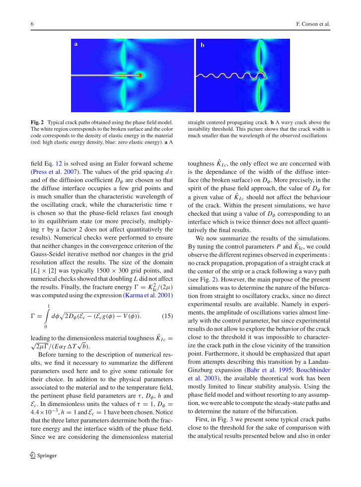
Fig. 2 Typical crack paths obtained using the phase field model.The white region corresponds to the broken surface and the colorcode corresponds to the density of elastic energy in the material(red: high elastic energy density, blue: zero elastic energy). a A
straight centered propagating crack. b A wavy crack above theinstability threshold. This picture shows that the crack width ismuch smaller than the wavelength of the observed oscillations
field Eq. 12 is solved using an Euler forward scheme(Press et al. 2007). The values of the grid spacing dxand of the diffusion coefficient Dφ are chosen so thatthe diffuse interface occupies a few grid points andis much smaller than the characteristic wavelength ofthe oscillating crack, while the characteristic time τ
is chosen so that the phase-field relaxes fast enoughto its equilibrium state (or more precisely, multiply-ing τ by a factor 2 does not affect quantitatively theresults). Numerical checks were performed to ensurethat neither changes in the convergence criterion of theGauss-Seidel iterative method nor changes in the gridresolution affect the results. The size of the domain[L] × [2] was typically 1500 × 300 grid points, andnumerical checks showed that doubling L did not affectthe results. Finally, the fracture energy � = K 2
Ic/(2µ)
was computed using the expression (Karma et al. 2001)
� =1∫
0
dφ√
2Dφ(Ec − (Ecg(φ) − V (φ)). (15)
leading to the dimensionless material toughness K I c =√2µ�/(EαT �T
√b).
Before turning to the description of numerical res-ults, we find it necessary to summarize the differentparameters used here and to give some rationale fortheir choice. In addition to the physical parametersassociated to the material and to the temperature field,the pertinent phase field parameters are τ , Dφ , h andEc. In dimensionless units the values of τ = 1, Dφ =4.4×10⁻³, h = 1 and Ec = 1 have been chosen. Noticethat the three latter parameters determine both the frac-ture energy and the interface width of the phase field.Since we are considering the dimensionless material
toughness K I c, the only effect we are concerned withis the dependance of the width of the diffuse inter-face (the broken surface) on Dφ . More precisely, in thespirit of the phase field approach, the value of Dφ fora given value of K I c should not affect the behaviourof the crack. Within the present simulations, we havechecked that using a value of Dφ corresponding to aninterface which is twice thinner does not affect quanti-tatively the final results.
We now summarize the results of the simulations.By tuning the control parameters P and KIc, we couldobserve the different regimes observed in experiments :no crack propagation, propagation of a straight crack atthe center of the strip or a crack following a wavy path(see Fig. 2). However, the main purpose of the presentsimulations was to determine the nature of the bifurca-tion from straight to oscillatory cracks, since no directexperimental results are available. Namely in experi-ments, the amplitude of oscillations varies almost line-arly with the control parameter, but since experimentalresults do not allow to explore the behavior of the crackclose to the threshold it was impossible to character-ize the crack path in the close vicinity of the transitionpoint. Furthermore, it should be emphasized that apartfrom attempts describing this transition by a Landau-Ginzburg expansion (Bahr et al. 1995; Bouchbinderet al. 2003), the available theoretical work has beenmostly limited to linear stability analysis. Using thephase field model and without resorting to any assump-tion, we were able to compute the steady-state paths andto determine the nature of the bifurcation.
First, in Fig. 3 we present some typical crack pathsclose to the threshold for the sake of comparison withthe analytical results presented below and also in order
123

Thermal fracture as a framework for quasi-static crack propagation 7
-0.15
0
0.15
0 2 4-0.25
0
0.25
0 1.35 2.7
a b
Fig. 3 a Crack tip trajectory below the threshold of linear insta-bility for a crack which was initially off center. P = 7.9 and1/KIc = 7.85. b Crack tip trajectory for an initially slightly off
center crack above the threshold of linear instability. P = 7.9and 1/KIc = 8.43
0
0.1
0.2
7.5 9.5 11.5
A2
1/K 1c
a
0
0.1
0.2
11 13 15
A2
1/K 1c
b
Fig. 4 a Square of the amplitude A of the oscillations forP = 7.89 as function of 1/KIc, which is related to the ampli-tude of the temperature gradient. b same as (a) with P = 3.95.
The linear behavior of A2 in the neighborhood of the transitionshows that the transition from straight to oscillatory propagationis supercritical (continuous)
to clarify the nature of the bifurcation. The first pathwas obtained with an initial straight crack which wasoff center and below the threshold. One can see dampedoscillations as the crack path returns to its equilibriumstate: a straight crack. The second path was obtainedwith an initial crack that was slightly off center (shiftedby 2 grid points away from the center) and slightlyabove the threshold. One can see oscillations of the paththat are amplified as the crack advances. These oscil-lations eventually saturate and the crack path becomesoscillating with a finite constant amplitude as observedin experiments. Using the model we were able to com-pute the amplitude of the oscillations when a steadystate was reached. The simulations showed that thesteady state is independant of initial conditions, such asthe initial position of the crack, and is a single valuedfunction of the control parameters. Typical results areshown in Fig. 4 where the square of the amplitude isplotted as a function of 1/K1c for a given value of P .One can see that above a threshold value of 1/K1c theamplitude of oscillations is no longer zero and scales
as the square root of the deviation from the thresh-old. The same behavior holds when using the valueof P as a control parameter. The amplitude curvestogether with the damped oscillations below the thresh-old and the amplified oscillations above the thresholdindicate that the bifurcation is supercritical or continu-ous.
For values of the control parameters well above thethreshold, we were not able to recover complex pathssimilar to those observed in experiments (Yuse andSano 1993). This may be due to the fact that wellabove the threshold the quasistatic approximation isno longer valid and dynamic effects through the tem-perature field as given by Eq. 4 become relevant. It isnonetheless interesting to note that the observed cres-cent-like path in Fig. 5 exhibits a striking similitudewith paths obtained when cutting a thin elastic sheetwith a moving thick object (Ghatak and Mahadevan2003; Audoly et al. 2005) and with crack paths obtainedduring drying of silicate sol-gel films fabricated usingspin-coating techniques (Sendova and Willis 2003).
123

8 F. Corson et al.
-0.33
0
0.33
0 1.35 2.7
Fig. 5 Crack tip trajectory for a crack deep in the nonlinearregime, that is far above the threshold of the instability. Thevalues of the control parameters are P = 7.9 and 1/KIc =11.6. Note the striking resemblance to crack paths appearing in(Ghatak and Mahadevan 2003; Audoly et al. 2005; Sendova andWillis 2003)
The phase diagram in Fig. 6a shows the thresholdfor the propagation of a centered straight crack andfor the transition to a wavy crack propagation in the1/P–1/K1c phase space. It can be seen that the theo-retical predictions presented in Sec. 4 are in quantita-tive agreement with numerical results of the phase fieldmodel without any adjustable parameters. The sameagreement is reached when considering the dimension-less wavelength at the threshold of the transition fromstraight to wavy crack path (see Fig. 6b). For this lat-ter quantity, one should also note the good agreementwith experimental values for small values of 1/P (lin-ear behavior with λ 0.28 + 2.0/P) (Ronsin et al.1995). Moreover, the phase field computation and ourtheoretical approach lead to the same deviation fromthe linear behavior for 1/P > 0.2, where the discrep-ancy between the present results and those reported in
Adda-Bedia and Pomeau (1995) become significant.This feature has also been observed in experiments(Ronsin 1996).
4 Theoretical analysis
We now turn to a theoretical study of the transition fromstraight to oscillatory crack propagation. As in previ-ous theoretical treatments (Marder 1994; Adda-Bediaand Pomeau 1995; Bouchbinder et al. 2003), the anal-ysis is based on the calculation of the stress intensityfactors (SIFs). However, here, they are computed tofirst order for an arbitrary trajectory without using theinfinite plate approximation and without the restric-tion that the crack tip lies at the center of the sample.Within the framework of linear elastic fracture mechan-ics, the propagation of a crack is governed by the sin-gular behavior of the stress field in the vicinity of itstip, as defined in Eq. 1. The propagation laws we useare the Irwin criterion defined in Eq. 2 and the principleof local symmetry (PLS) defined in Eq. 3. To calculatethe SIFs, one must solve the equilibrium equations∂σi j
∂x j= 0, ∇2σi i = −∇2T (x), (16)
with the boundary conditions (7) at the sides of the plateand the additional boundary condition at the crack sur-face
σi j n j = 0, (17)
where −→n is the normal to the crack faces.
oscillating mode
straight mode
no propagation
a
1/P
1/K
Ic
0.40.30.20.10
15
10
5
0
b
1/P0.40.30.20.10
2
1.5
1
0.5
0
Fig. 6 Main theoretical and numerical results. a The phase dia-gram of the different states of the system as a function of the twocontrol parameters P and KIc. b The wavelength λ as a functionof P at the transition from straight to wavy crack propagation. Inboth figures, the symbols + and × correspond to the numerical
results obtained from the phase field model, the solid lines cor-respond to the analytical calculation presented in Sect. 4 and thedashed lines correspond to the results reported in (Adda-Bediaand Pomeau 1995)
123

Thermal fracture as a framework for quasi-static crack propagation 9
To investigate the transition from a straight to anoscillating regime, we consider a small deviation froma straight centered crack,
y(x) = Ah(x), (18)
where h(x) is defined for x ≤ 0 (see Fig. 1) and|A| � 1. We expand the displacement and stress fieldsto first order as
ui = u(0)i + Au(1)
i + O(A2), (19)
σi j = σ(0)i j + Aσ
(1)i j + O(A2). (20)
The SIF KI (resp. KII) is an even (resp. odd) functionof A. Therefore their expansions have the form
KI = K (0)I + O(A2), (21)
KII = AK (1)II + O(A3). (22)
Note that in particular, KII = 0 for a straight cen-tered crack. The different terms of the above expansioncan be determined by solving the equilibrium equationsusing repeatedly the Wiener-Hopf method. The detailsof these calculations are presented in Appendix A. Herewe simply summarize the calculation of K (1)
II , which is
novel. K (1)II can be written as
K (1)II [h(x)] = κh(0) + K (1)
II [h(x) − h(0)], (23)
which amounts to decomposing the general probleminto that of a straight off-center crack and that of anoscillating crack with a centered tip. The latter prob-lem was solved by Adda-Bedia and Pomeau (1995),yielding
K (1)II [h(x) − h(0)] = K (0)
I
2h′(0)
+0∫
−∞dx
∂
∂x
[σ (0)
xx (x, 0)(h(x) − h(0))]
p+(−x) ,
(24)
where p+(x) is a weight function that does not dependon the physical parameters. We have generalized theresults of Adda-Bedia and Pomeau (1995) with thecalculation of the contribution κh(0) to obtain
K (1)II [h(x)] =
[cK (0)
I − ∂
∂lK (0)
I
]h(0) + K (0)
I
2h′(0)
+0∫
−∞dx
∂
∂x
[σ (0)
xx (x, 0)h(x)]
p+(−x), (25)
Fig. 7 K (0)I as a function of l, for P = 5. Recall that l is the
distance of the crack tip from the boundary of the cold bath. Thethreshold of incipient growth of a centered straight crack is givenby KIc = K (0)
I (lc), where lc is the location of the maximum of
K (0)I (l)
where c 1.272 is a numerical constant (see Appendixfor details).
Having calculated the SIFs to first order, we can nowexamine the particular form taken by the crack propa-gation criteria for a small perturbation. The Irwin crite-rion reads K (0)
I = KIc. The transition to a propagatingstraight crack is thus governed by the existence of l suchthat K (0)
I (l) = KIc. This occurs when KIc = K (0)I (lc),
where lc is the location of the maximum of K (0)I (l)
(see Fig. 7). This condition determines the transitioncurve in Fig. 2 from no crack propagation to the prop-agation of a centered straight crack. Also, above thepropagation threshold Eq. 21 shows that to first orderin A, the distance between the cold front and the cracktip, which is determined by K I [h(x)], does not dependon the crack path y(x) = Ah(x). This simplifies theproblem, as we can parameterize the “time” evolutionof the crack path by the position of its tip in a coordi-nate system attached to the plate. If h(x) now describesthe crack path in such a coordinate system, the value ofK (1)
II when the tip is at the point x is simply given by
K (1)II (x) =
[cK (0)
I − ∂
∂lK (0)
I
]h(x) + K (0)
I
2h′(x)
+0∫
−∞du
∂
∂u
[σ (0)
xx (u, 0)h(x + u)]
p+(−u). (26)
123
10 F. Corson et al.
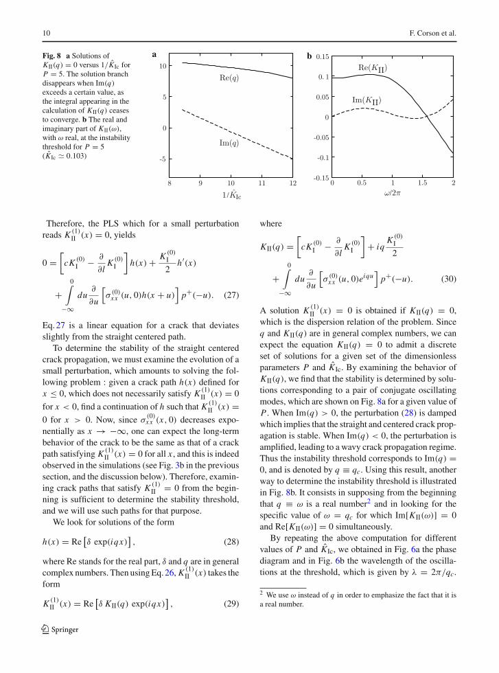
Fig. 8 a Solutions ofKII(q) = 0 versus 1/KIc forP = 5. The solution branchdisappears when Im(q)
exceeds a certain value, asthe integral appearing in thecalculation of KII(q) ceasesto converge. b The real andimaginary part of KII(ω),with ω real, at the instabilitythreshold for P = 5(KIc 0.103)
Therefore, the PLS which for a small perturbationreads K (1)
II (x) = 0, yields
0 =[
cK (0)I − ∂
∂lK (0)
I
]h(x) + K (0)
I
2h′(x)
+0∫
−∞du
∂
∂u
[σ (0)
xx (u, 0)h(x + u)]
p+(−u). (27)
Eq. 27 is a linear equation for a crack that deviatesslightly from the straight centered path.
To determine the stability of the straight centeredcrack propagation, we must examine the evolution of asmall perturbation, which amounts to solving the fol-lowing problem : given a crack path h(x) defined forx ≤ 0, which does not necessarily satisfy K (1)
II (x) = 0
for x < 0, find a continuation of h such that K (1)II (x) =
0 for x > 0. Now, since σ(0)xx (x, 0) decreases expo-
nentially as x → −∞, one can expect the long-termbehavior of the crack to be the same as that of a crackpath satisfying K (1)
II (x) = 0 for all x , and this is indeedobserved in the simulations (see Fig. 3b in the previoussection, and the discussion below). Therefore, examin-ing crack paths that satisfy K (1)
II = 0 from the begin-ning is sufficient to determine the stability threshold,and we will use such paths for that purpose.
We look for solutions of the form
h(x) = Re[δ exp(iqx)
], (28)
where Re stands for the real part, δ and q are in generalcomplex numbers. Then using Eq. 26, K (1)
II (x) takes theform
K (1)II (x) = Re
[δ KII(q) exp(iqx)
], (29)
where
KII(q) =[
cK (0)I − ∂
∂lK (0)
I
]+ iq
K (0)I
2
+0∫
−∞du
∂
∂u
[σ (0)
xx (u, 0)eiqu]
p+(−u). (30)
A solution K (1)II (x) = 0 is obtained if KII(q) = 0,
which is the dispersion relation of the problem. Sinceq and KII(q) are in general complex numbers, we canexpect the equation KII(q) = 0 to admit a discreteset of solutions for a given set of the dimensionlessparameters P and KIc. By examining the behavior ofKII(q), we find that the stability is determined by solu-tions corresponding to a pair of conjugate oscillatingmodes, which are shown on Fig. 8a for a given value ofP . When Im(q) > 0, the perturbation (28) is dampedwhich implies that the straight and centered crack prop-agation is stable. When Im(q) < 0, the perturbation isamplified, leading to a wavy crack propagation regime.Thus the instability threshold corresponds to Im(q) =0, and is denoted by q ≡ qc. Using this result, anotherway to determine the instability threshold is illustratedin Fig. 8b. It consists in supposing from the beginningthat q ≡ ω is a real number2 and in looking for thespecific value of ω = qc for which Im[KII(ω)] = 0and Re[KII(ω)] = 0 simultaneously.
By repeating the above computation for differentvalues of P and KIc, we obtained in Fig. 6a the phasediagram and in Fig. 6b the wavelength of the oscilla-tions at the threshold, which is given by λ = 2π/qc.
2 We use ω instead of q in order to emphasize the fact that it isa real number.
123

Thermal fracture as a framework for quasi-static crack propagation 11
These figures show that a good quantitative agreementis reached with the numerical results of the phase fieldmodel for both the wavy instability threshold and thewavelength at the transition.
Our results for the instability threshold differ fromthose of Adda-Bedia and Pomeau (1995), in which thethreshold was determined by the existence of a real
solution qc such that K (1)II [sin ωx] = d K (1)
IIdω
[sin ωx] =0 for x = 0 and the stability criterion was based on thesign of K (1)
II [sin ωx]. In general, such a solution has no
reason to satisfy K (1)II (x) = 0 for x = 0. Indeed, the
wavelengths predicted by these two criteria (i.e., thepresent one and the one of Adda-Bedia and Pomeau1995) differ significantly, especially for small values ofP (see Fig. 6b). The thresholds predicted also differ, butless notably (see Fig. 6a). As can be seen in Fig. 8b, thedeviations between the estimates of KIc and λ obtainedby the two methods are related to the vertical and hori-zontal distances between the minimum of Im(KII) andits intersection with Re(KII), and the vertical distancescales as the square of the horizontal one.
5 Conclusions
In this paper we address the problem of crack pathprediction for quasi-static crack propagation. We usedthe framework of the thermal crack experiment since itis a well controlled experiment, and the best knownto us. The reason is that stresses are induced inter-nally by an imposed thermal gradient that can be easilytuned by external parameters leading to a steady statepropagation.
Our main result is that by using only the Principleof Local Symmetry and the Griffith criterion one canreproduce the phase diagram of the problem, namelypredict the existence of the two instabilities (no-crack tostraight crack and straight to oscillatory propagation).Furthermore, we show that these criteria are sufficientto determine the instability threshold and the wave-length of the oscillations without introducing additionalhypotheses. Interestingly, our theoretical results agreevery well with the numerical simulations of the phasefield model. This strengthens the theoretical approachbased on the classical LEFM theory combined withthe two propagation criteria, namely PLS and Griffithcriterion (but mostly PLS). This work joins a recenteffort to explain a variety of instabilities of cracks,
namely the branching instability (Katzav et al. 2007b)and the out-of-the-plane roughening instability (Katzavet al. 2007a) using these general criteria (i.e., LEFM +Griffith criterion + PLS),
Another achievement of this work is the fact thatthe phase field model allows to clarify the nature ofthe transition between straight and oscillatory cracks,which is convincingly shown to be supercritical or con-tinuous. This is achieved thanks to the high resolutionof the phase field approach near the transition point andthe relative ease at which in-silico experiments can beperformed under different conditions. This also sug-gests that the phase field model is more adapted thanthe classical methods for crack path tracking, especiallywhen considering complex moving shapes, in view ofits relatively low computational cost. It is therefore agood candidate to describe complicated crack patternssuch as spirals or crescents as the ones observed in(Sendova and Willis 2003), branching (Katzav et al.2007b; Henry 2008) and interacting cracks (Marconiand Jagla 2005). A real challenge for this approachwould be to reproduce propagation of cracks in 3D,which can help to infer their laws of motion from suchwell controlled numerical experiments.
Appendix: the straight off-center crack
In the following, we present briefly the method of reso-lution for a straight off-center crack in a thermal gradi-ent. The method of resolution follows the same steps asin Adda-Bedia and Pomeau (1995). Consider a straightcrack which is slightly above/below the center of thestrip, namely its location is given by y(x) = Ah(0) ≡δ. Due to the absence of symmetry with respect to thecenter of the strip y = 0, let us split the displacement,strain and stress fields in the strip as follows
f (x, y) = 1
2
(f +(x, y) (y − δ)
+ f −(x, y)(δ − y)), (31)
where is the Heaviside function and f stands for anycomponent of the elastic fields. Let us also define
[ f ](x) = 1
2
(f +(x, δ) − f −(x, δ)
), (32)
Note that all the elastic fields are continuous in theunbroken regions. However, along the crack surfacesthe displacements might be discontinuous while σyy
and σxy are continuous there. Thus, for this specific
123
12 F. Corson et al.
problem, the boundary conditions (7,17) can be rewrit-ten as
σ±yy(x,±1) = σ±
xy(x,±1) = 0, (33)[σyy
](x) = [
σxy](x) = 0, (34)
[ux ] (x) = [uy
](x) = 0 for x > 0, (35)
σ±yy(x, δ) = σ±
xy(x, δ) = 0 for x < 0, (36)
Now, we Fourier transform along the x direction allthe elastic fields and the temperature field and plugthem into the equilibrium Eq. 16 and into the bound-ary conditions (33, 34). After some algebraic manipu-lations, this yields relations of the type
([ux
](k)[
u y](k)
)=
(Cxx (k) Cxy(k) Dx (k)
Cyx (k) Cyy(k) Dy(k)
)⎛
⎝σxy(k, δ)
σyy(k, δ)
T (k)
⎞
⎠,
(37)
Performing the first-order expansions in δ, as given byEqs. 19–20:
ui (k, δ) = u(0)i (k, 0) + δu(1)
i (k, 0), (38)
σi j (k, δ) = σ(0)i j (k, 0) + δσ
(1)i j (k, 0), (39)
and inverting (37) gives the final result
σ (0)yy (k, 0) = −F(k)
[u(0)
y
](k, 0) + D(k)T (k), (40)
σ (0)xx (k, 0) = H(k)σ (0)
yy (k, 0) + S(k)T (k), (41)
σ (1)xy (k, 0) = −P(k)
([u(1)
x
](k, 0) − ik
[u(0)
y
](k, 0)
)
+ ikσ (0)xx (k, 0), (42)
where
F(k) = ksinh2 k − k2
sinh 2k + 2k,
D(k) = 2(1 − cosh k)(sinh k − k)
sinh 2k + 2k,
H(k) = k2 + sinh2 k
sinh2 k − k2, (43)
S(k) = sinh k − k
sinh k + k,
P(k) = ksinh2 k − k2
sinh 2k − 2k.
The first step of resolution which involves only thezeroth-order expansion, i.e. the case of a straight cen-tered crack, is the calculation of K (0)
I . Using the bound-ary conditions (35, 36) to leading order and applying
the Wiener-Hopf method to Eq. 40 yields (Adda-Bediaand Pomeau 1995)
K (0)I =
+∞∫
−∞D(k)T (k)F+(k)
dk
2π, (44)
where
F(k) = F−(k)
F+(k), (45)
and F+(k) (F−(k)) is analytic in the upper (lower)half-plane, respectively.
To complete the calculation of the SIFs, we return tothe case of a straight off-center crack and determine thecoefficient κ appearing in Eq. 23. Using the boundaryconditions (35, 36) to first order in δ and applying againthe Wiener-Hopf method to Eq. 42 yields[u(1)
x
](k) = ik
[u(0)
y
](k) − 1
P−(k)
×+∞∫
−∞
ik′ P+(k′)σ (0)−xx (k′, 0)
k′ − k + iε
dk′
2iπ
+ α
P−(k)= − k
F−(k)
+∞∫
−∞
D(k′)T (k′)F+(k′)k′ − k + iε
dk′
2π
− 1
P−(k)
+∞∫
−∞
ik′ P+(k′)σ (0)−xx (k′, 0)
k′ − k + iε
dk′
2iπ+ α
P−(k),
(46)
where P(k) = P−(k)/P+(k) with P+(k) (P−(k))analytic in the upper (lower) half-plane, and ε is a van-ishingly small positive number. Notice that the solution
of[u(0)
y
](k) obtained from the zeroth order calcula-
tions has been used, and that σ (0)xx (x, 0) can be obtained
from Eq. 41. For both F(k) and P(k) the factorizationinto F±(k) and P±(k) can be achieved using a Padédecomposition, as previously explained in Bouchbinderet al. (2003); Katzav et al. (2007b). The unknown con-stant α is introduced because the decompositioninvolved in the Wiener-Hopf method is not unique.The value of α can be determined by noting that the[u(1)
x
](k) behaves as O(k−3/2) as k → ∞. Canceling
out the k−1/2 term on the r.h.s. yields
α = −+∞∫
−∞D(k)T (k)F+(k)
dk
2π, (47)
123

Thermal fracture as a framework for quasi-static crack propagation 13
and thus one has[u(1)
x
](k) =
(1
F−(k)− 1
P−(k)
)
×+∞∫
−∞D(k′)T (k′)F+(k′)dk′
2π
+ 1
F−(k)
+∞∫
−∞
−ik′D(k′)T (k′)F+(k′)k′−k+iε
dk′
2iπ.
(48)
Finally by looking at the asymptotic behavior of[u(1)
x
](k) as k → ∞ one has
κ = cK (0)I − ∂
∂lK (0)
I
−0∫
−∞
∂
∂xσ (0)
xx (x, 0)p+(−x)dx, (49)
where p+(x) is the inverse Fourier transform of P+(k)
and c is a numerical constant given by
c = limk→∞
(ik)32√
2
[1
F−(k)− 1
P−(k)
] 1.272. (50)
Using this value of κ in Eq. 23 yields 25.
References
Acerbi E, Braides A (1999) Approximation of free-discontinu-ity problems by elliptic functionals via �-convergence.Asymptot Anal 21:317–329
Adda-Bedia M, Pomeau Y (1995) Crack instabilties of a heatedglass strip. Phys Rev E 52:4105–4113
Adda-Bedia M, Arias R, Ben Amar M, Lund F (1999)Generalized Griffith criterion for dynamic fracture and thestability of crack motion at high velocities. Phys Rev E60:2366–2376
Ambrosio L, Tortorelli VM (1990) Approximation of function-als depending on jumps by elliptic functionals via �-con-vergence. Comm Pure Appl Math 43:999–1036
Ambrosio L, Tortorelli VM (1992) On the approximation of freediscontinuity problems. Boll Un Mat Ital B 6:105–123
Amestoy M, Leblond JB (1992) Crack paths in plane situations–II. Detailed form of the expansion of the stress instensityfactors. Int J Solids Struct 29:465–501
Aranson IS, Kalatsky VA, Vonokur VM (2000) Continuum fielddescription of crack propagation. Phys Rev Lett 85:118–121
Audoly B, Reis PM, Roman B (2005) Cracks in brittle elasticplates: when geometry rules fracture paths. Phys Rev Lett95:025502
Bahr HA, Gerbatsch A, Bahr U, Weiss HJ (1995) Oscillatoryinstability in thermal cracking: a first-order phase-transi-tion phenomenon. Phys Rev E 52:240–243
Barenblatt G., Cherepanov G (1961) On brittle cracks under lon-gitudinal shear. PMM 25:1110–1119
Bilby BA, Cardew GE (1975) The crack with a kinked tip. IntJ Fract 11:708–712
Bouchbinder E, Hentschel HGE, Procaccia I (2003) Dynamicalinstabilities of quasistatic crack propagation under thermalstress. Phys Rev E 68:036601
Braides A (1998) Approximation of free-discontinuity problems.Springer-Verlag, Berlin
Broberg KB (1999) Cracks and fracture. Academic Press,London
Caginalp G, Fife P (1986) Phase field methods for interfacialboundaries. Phys Rev B 33:7792–7794
Collins JB, Levine H (1986) Diffuse interface model of diffu-sion-limited cristal growth. Phys Rev B 31:6119–6122
Cotterell B, Rice JR (1980) Slightly curved or kinked cracks. IntJ Fract 16:155–169
Deegan RD, Chheda S, Patel L, Marder M, Swinney HL, KimJ, de Lozanne A (2003) Wavy and rough cracks in silicon.Phys Rev E 67:066209
Eastgate LO, Sethna JP, Rauscher M, Cretegny T, Chen CS,Myers CR (2002) Fracture in mode I using a conservedphase-field model. Phys Rev E 65:036117
Erdogan G, Sih GC (1963) On the crack extension in platesunder plane loading and transverse shear. J Basic Eng 85:519–527
Etchebarria B, Folch R, Karma A, Plapp P (2004) Quantita-tive phase-field model of alloy solidification. Phys Rev E70:061604
Fineberg J, Marder M (1999) Instability in dynamic fracture.Phys Rep 313:2–108
Folch R, Casademunt J, Hernandez-Machado A (2000) Viscousfingering in liquid crystals: anisotropy and morphologicaltransitions. Phys Rev E 61:6632–6638
Freund LB (1990) Dynamic Fracture Mechanics. CambridgeUniversity Press, Cambridge
Ghatak A, Mahadevan L (2003) Crack street: the cycloidal wakeof a cylinder ripping through a thin solid sheet. Phys RevLett 91:215507
Gol’dstein RV, Salganik RL (1974) Brittle fracture of solids witharbitrary cracks. Int J Fract 10:507–523
Griffith AA (1920) The phenomenon of rupture and flow in solid.Phil Trans R Soc Lond Ser A 221:163–198
Hakim V, Karma A (2005) Crack path prediction in anisotropicbrittle materials. Phys Rev Lett 95:235501
Hakim V, Karma A (2009) Laws of crack motion and phase-field models of fracture. J Mech Phys Solids 57:342–368
Henry H, Levine H (2004) Dynamic instabilities of fractureunder biaxial strain using a phase field model. Phys RevLett 93:105504
Henry H (2008) Study of the branching instability using a phasefield model of inplane crack propagation. EPL 83:16004
Hodgdon JA, Sethna JP (1993) Derivation of a general three-dimensional crack-propagation law–A generalization of theprinciple of local symmetry. Phys Rev B 47:4831–4840
Irwin GR (1957) Analysis of stresses and strains near the end ofa crack traversing a plate. J Appl Mech 24:361–364
Karma A, Rappel WJ (1998) Quantitative phase-field modelingof dendritic growth in two and three dimensions. Phys RevE 57:4323–4349
123
14 F. Corson et al.
Katzav E, Adda-Bedia M, Derrida B (2007a) Fracture surfacesof heterogeneous materials: a 2D solvable model. EPL78:46006
Katzav E, Adda-Bedia M, Arias R (2007b) Theory of dynamiccrack branching in brittle materials. Int J Fract 143:245–271
Karma A, Kessler DA, Levine H (2001) Phase-field model ofmode III dynamic fracture. Phys Rev Lett 87:045501
Karma A, Lobkovsky AE (2004) Unsteady crack motion andbranching in a phase field model of brittle fracture. PhysRev Lett 92:245510
Kobayashia R, Warren JA (2005) Modeling the formation anddynamics of polycrystals in 3D. Physica A 356:127–132
Leblond JB (1989) Crack paths in plane situations— I. Generalform of the expansion of the stress instensity factors. Int JSolids Struct 25:1311–1325
Leblond JB (2003) Mécanique de la rupture fragile et ductile.Hermes Science Publications, Paris
Marconi VI, Jagla EA (2005) Diffuse interface approach to brit-tle fracture. Phys Rev E 71:036110
Marder M (1994) Instability of a crack in a heated strip. PhysRev E 49:51–54
Pham VB, Bahr HA, Bahr U, Balke H, Weiss HJ (2008) Globalbifurcation criterion for oscillatory crack path instability.Phys Rev E 77:066114
Press WH, Teukolsky SA, Vetterling WT, Flannery BP(2007) Numerical recipes. Cambridge University Press,Cambridge
Ronsin O, Heslot F, Perrin B (1995) Experimental studyof quasistatic brittle crack propagation. Phys Rev Lett75:2352–2355
Ronsin O (1996) Etude expérimentale de la propagation defractures dirigées en milieu fragile. PhD thesis, UniversitéParis VI
Ronsin O, Perrin B (1998) Dynamics of quasistatic directionalcrack growth. Phys Rev E 58:7878–7886
Sakaue K, Yoneyama S, Kikuta H, Takashi M (2008) Evaluatingcrack tip stress field in a thin glass plate under thermal load.Eng Fract Mech 75:1015–1026
Sasa S, Sekimoto K, Nakanishi H (1994) Oscillatory instabilityof crack propagations in quasi-static fracture. Phys Rev E50:1733–1736
Sendova M, Willis K (2003) Spiral and curved periodic crackpatterns in sol-gel films. Appl Phys A 76:957–959
Yang B, Ravi-Chandar K (2001) Crack path instabilities in aquenched glass plate. J Mech Phys Solids 49:91–130
Yoneyama S, Sakaue K, Kikuta H, Takashi M (2006) Instanta-neous phase-stepping photoelasticity for the study of crackgrowth behaviour in a quenched thin glass plate. Meas SciTechnol 17:3309–3316
Yoneyama S, Sakaue K, Kikuta H, Takashi M (2008) Obser-vation of stress field around an oscillating crack tip in aquenched thin glass plate. Exp Mech 48:367–374
Yuse A, Sano M (1993) Transition between crack patterns inquenched glass plates. Nature 362:329–331
Yuse A, Sano M (1997) Instabilities of quasi-static crack patternsin quenched glass plates. Physica D 108:365–378
123