thermal enhancement of interference effects in quantum point contacts
DESCRIPTION
Thermal Enhancement of Interference Effects in Quantum Point Contacts. Adel Abbout, Gabriel Lemarié and Jean-Louis Pichard Phys. Rev. Lett. 106, 156810 (2011). IRAMIS/SPEC CEA Saclay Service de Physique de l’Etat Condensé, 91191 Gif Sur Yvette cedex, France. - PowerPoint PPT PresentationTRANSCRIPT

Thermal Enhancement of Interference Effects in Quantum Point Contacts
Adel Abbout, Gabriel Lemarié and Jean-Louis PichardPhys. Rev. Lett. 106, 156810 (2011)
IRAMIS/SPEC CEA Saclay
Service de Physique de l’Etat Condensé, 91191 Gif Sur Yvette cedex, France

Electron Interferometer formed with a quantum point contact and another scatterer in a 2DEG
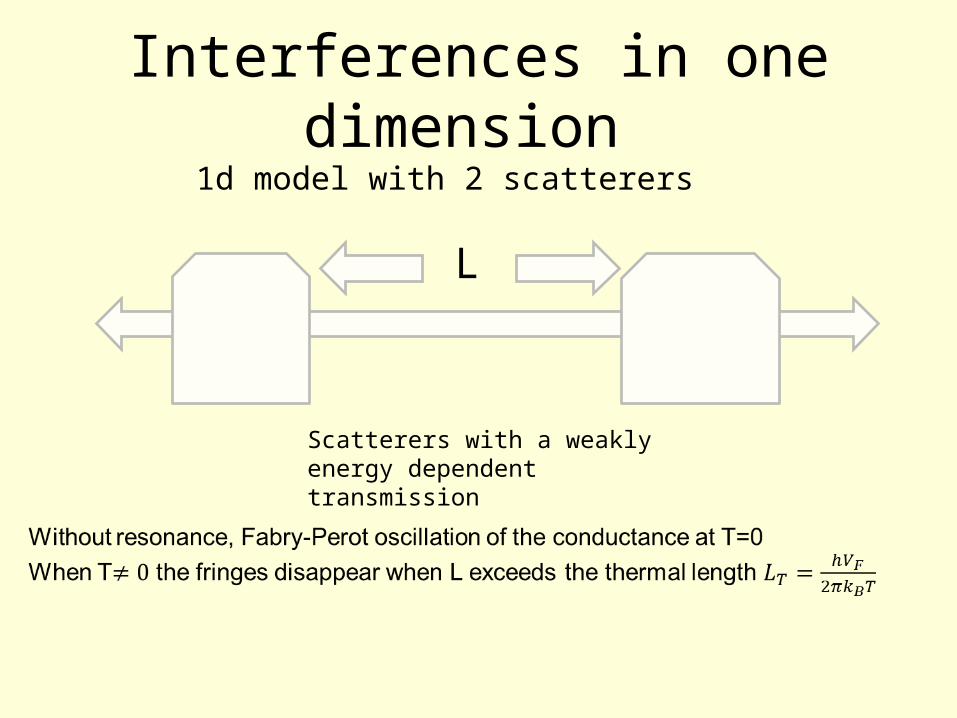
Interferences in one dimension 1d model with 2 scatterers
Scatterers with a weakly energy dependent transmission
L
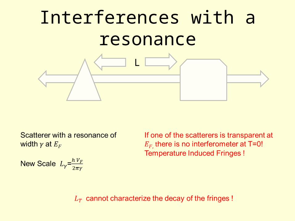
Interferences with a resonance
L
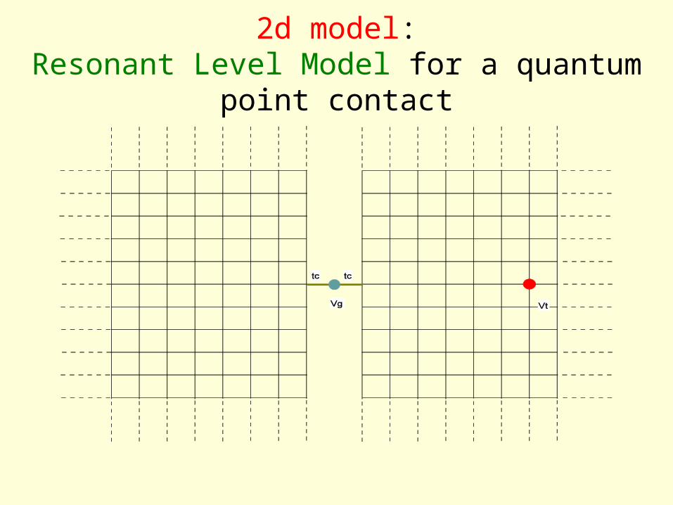
2d model:Resonant Level Model for a quantum point
contact
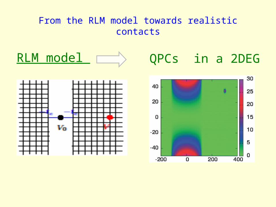
From the RLM model towards realistic contacts
RLM model QPCs in a 2DEG

SGM imaging Conductance of the QPC as a function of the tip position
(Harvard, Stanford, Cambridge, Grenoble,…)Topinka et al., Physics Today (Dec. 2003)
)pwithout ti() tipwith( ggg
g falls off with distance r from the QPC, exhibiting fringes spaced by F/2
2DEG , QPC AFM cantilever
The charged tip creates a depletion region inside the 2deg which can be scanned around the nanostructure (qpc)
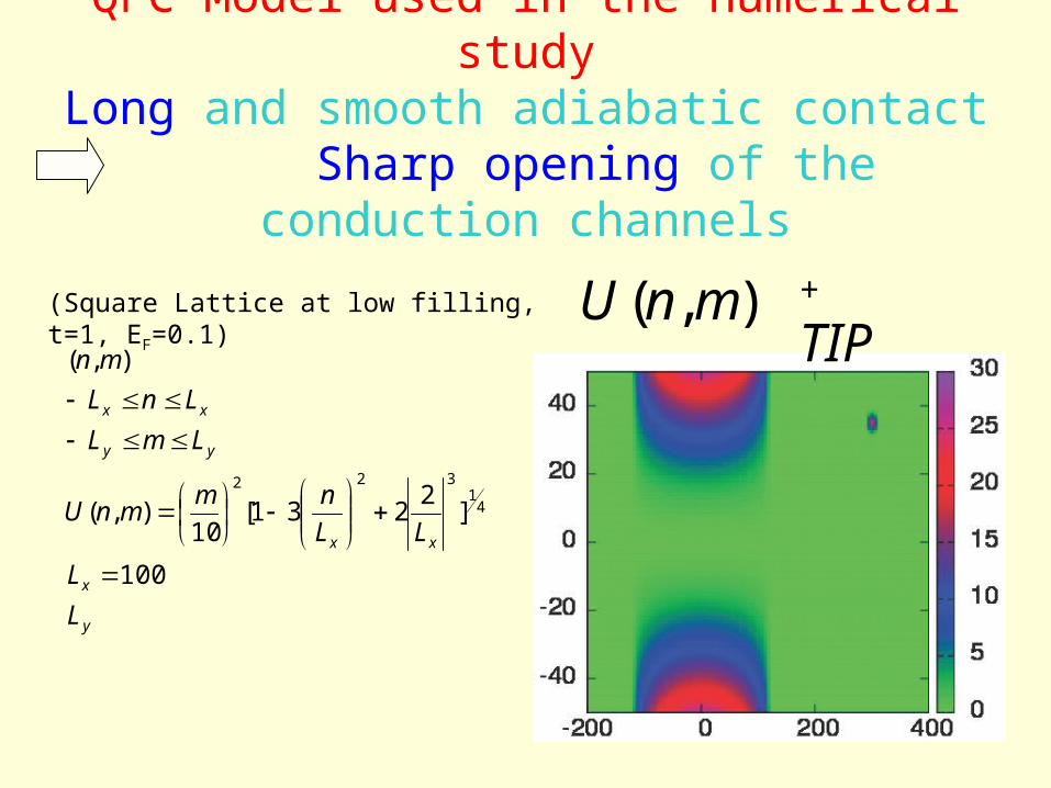
QPC Model used in the numerical studyLong and smooth adiabatic contact
Sharp opening of the conduction channels
y
x
xx
yy
xx
L
L
LL
nmmnU
LmL
LnL
mn
100
]2
231[10
),(
),(
41
322
),( mnU + TIP(Square Lattice at low filling, t=1, EF=0.1)

QPC biased at the beginning of the first plateau(Tip: V=1)
T=0 T = 0.01 EF

QPC biased at the beginning of the second plateau(Tip: V=-2)
T=0 T =0.035 EF
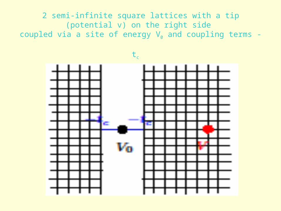
Resonant Level Model
2 semi-infinite square lattices with a tip (potential v) on the right side
coupled via a site of energy V0 and coupling terms -tc

Self-energies describing the coupling to leads expressed in terms of surface elements of the lead GFs
Method of the mirror images for the lead GFs. Dyson equation for the tip
• Transmission without tip
~ Lorentzian of width
• Transmission with tip
(Generalized Fisher-Lee formula)
rlrlrl
lrlr
lr
iIR
IIRRVE
IIET
,,,
220
0
4)(
0,0,11lim)exp(
1
2
)]2/2(exp[2/32
xGV
Vi
xO
x
kxi
t
Rr
x
c
r
rrr
I4
FEE Narrow resonance:
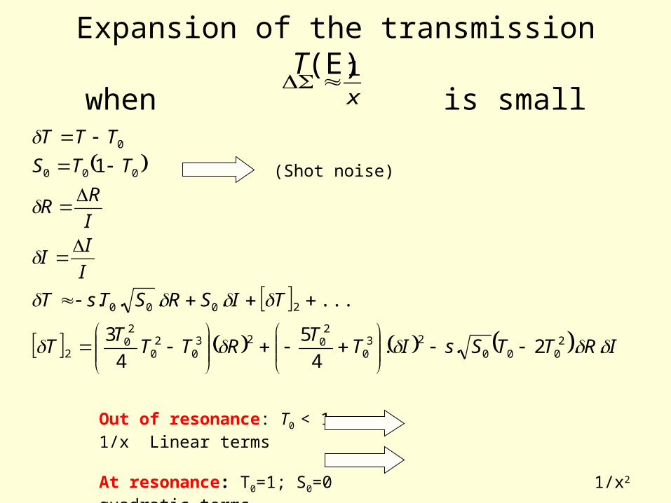
Expansion of the transmission T(E) when is small
x
1
IRTTSsITT
RTTT
T
TISRSTsT
I
II
I
RR
TTS
TTT
..2..4
5
4
3
.......
1
2000
230
2023
02
0
20
2
2000
000
0
Out of resonance: T0 < 1, 1/x Linear terms
At resonance: T0=1; S0=0 1/x2 quadratic terms
(Shot noise)
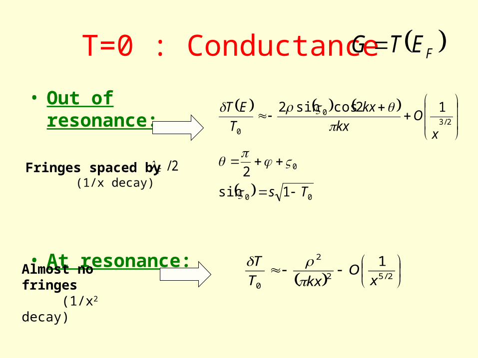
T=0 : Conductance
• Out of resonance:
• At resonance:
00
0
2/30
0
1sin
2
12cossin2
Ts
xO
kx
kx
T
ET
Fringes spaced by (1/x decay)
2/52
2
0
1
xO
kxT
T
2/F
Almost no fringes (1/x2 decay)
FETG
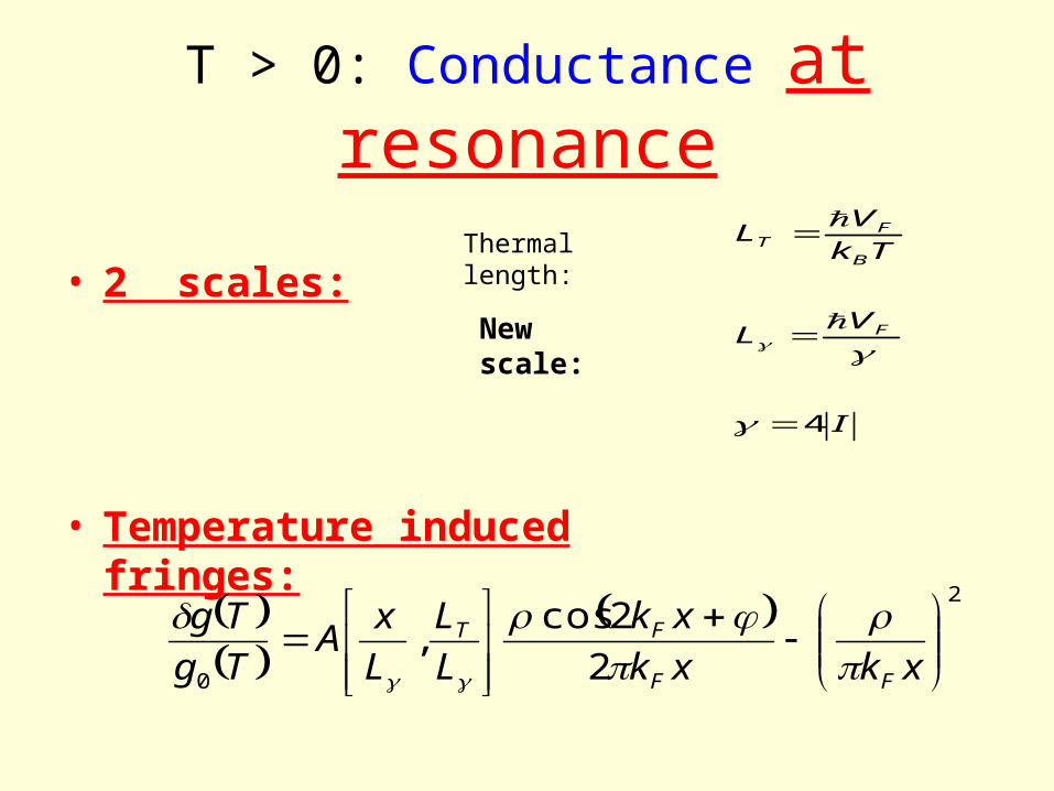
T > 0: Conductance at resonance
• 2 scales:
• Temperature induced fringes:
I
VL
Tk
VL
F
B
FT
4
Thermal length:
New scale:
2
0 2
2cos,
xkxk
xk
L
L
L
xA
Tg
Tg
FF
FT

Rescaled Amplitude
L
Lerfc
L
L
L
xA TT
8.,
1. Universal T-independent decay:
L
xexp2
2. Maximum for
TLx8
Bottom to top: increasing temperatureFL 2

Numerical simulations and analytical resultsIncreasing temperature (top to bottom)
20//2//4.0
10//20//40//2/
Fc
F
T
Vt
L
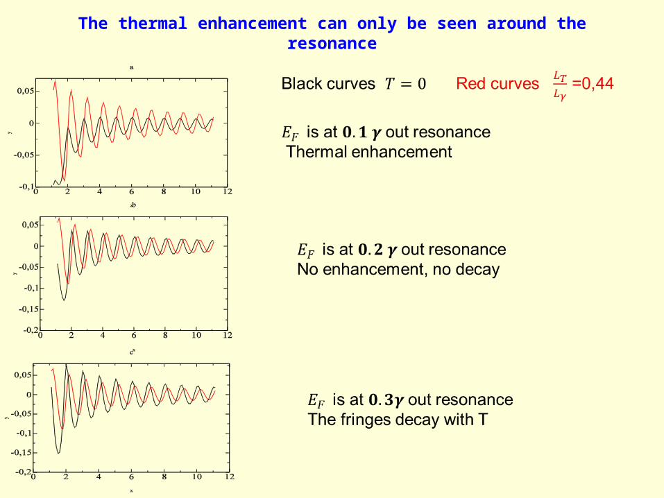
The thermal enhancement can only be seen around the resonance
RLM model QPC ?
• The expansion obtained in the RLM model can be extended to the QPC, if one takes the QPC staircase function instead of the RLM Lorentzian for T0(E).
• The width of the energy interval where
S0=T0(1-T0) is not negligible for the QPC plays the role of the of the RLM model for the QPC.
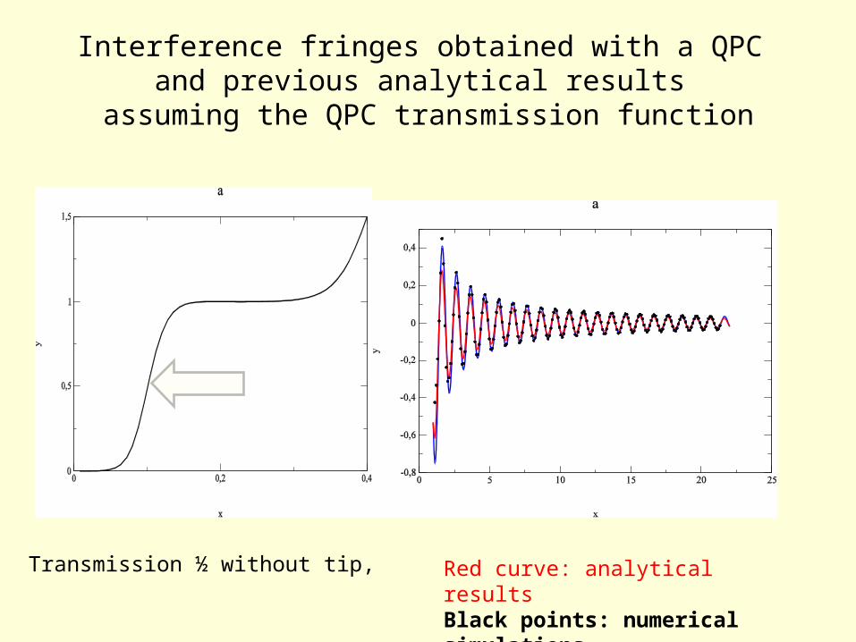
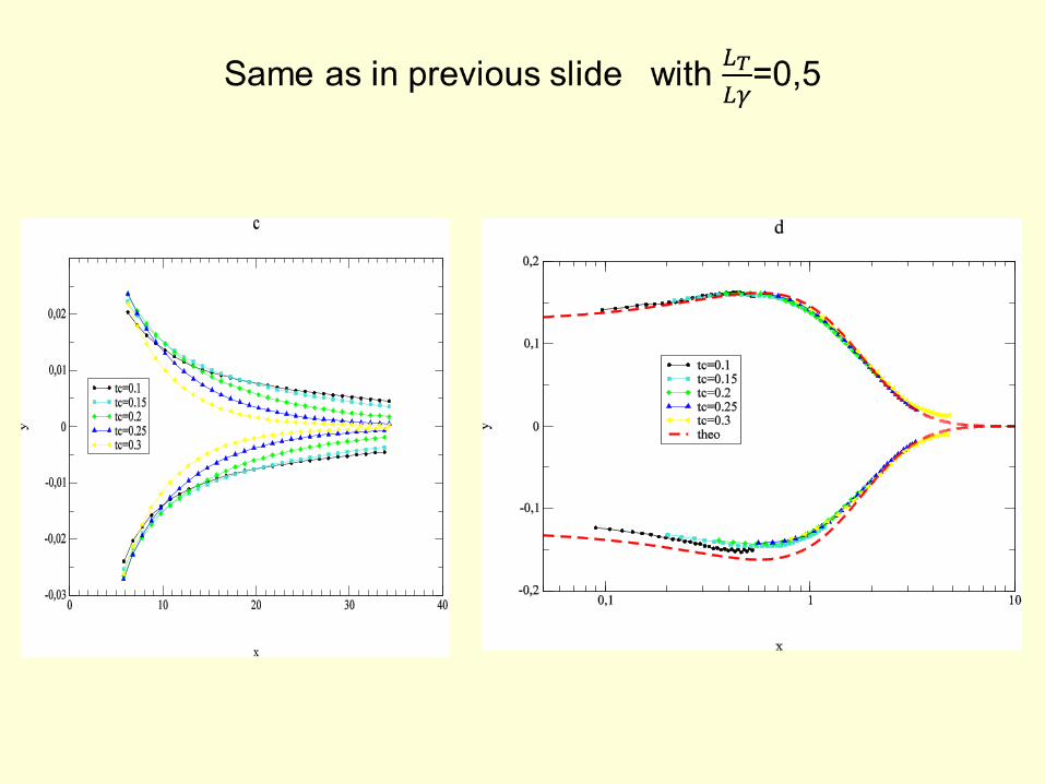
Interference fringes obtained with a QPC and previous analytical results
assuming the QPC transmission function
Transmission ½ without tip, Red curve: analytical resultsBlack points: numerical simulations

Peak to peak amplitude
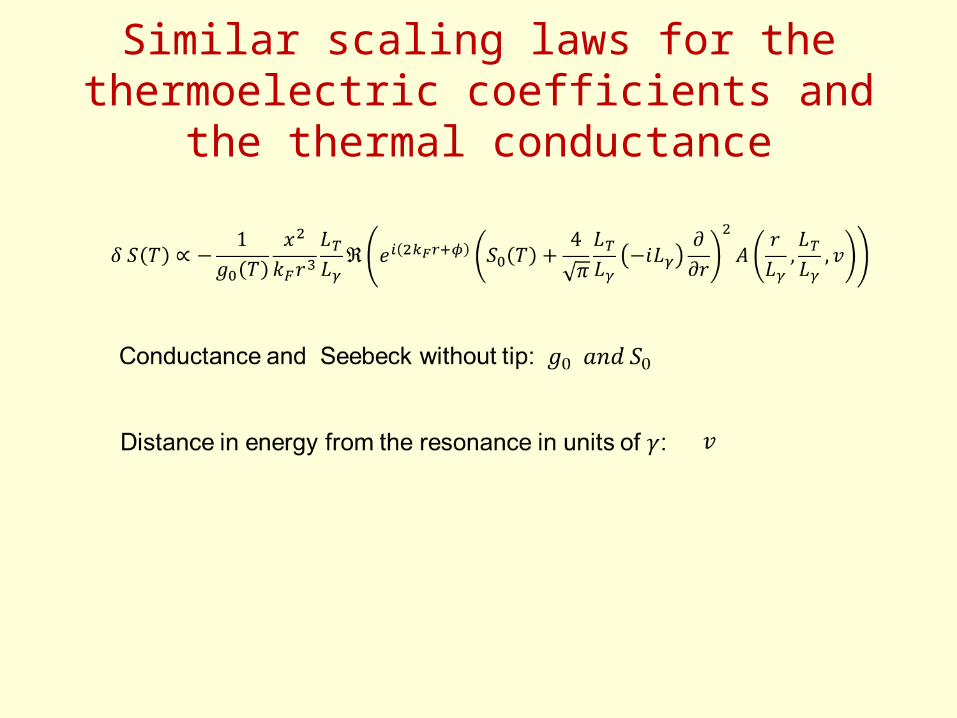
Similar scaling laws for the thermoelectric coefficients and the thermal conductance

Summary