thermal deformation of gas metal arc welding on aluminum alloy … · 2017-12-20 · thermal...
TRANSCRIPT

* Corresponding author. Tel.: +6 03 8946 4384; Fax: +6 03 8656 7122 E-mail addresses: [email protected] (M. I. S. Ismail) © 2018 by the authors; licensee Growing Science, Canada. doi: 10.5267/j.esm.2017.11.003
Engineering Solid Mechanics (2018) 21-26
Contents lists available at GrowingScience
Engineering Solid Mechanics
homepage: www.GrowingScience.com/esm
Thermal deformation of gas metal arc welding on aluminum alloy T-joints
Mohd Idris Shah Ismail*, Mariyam Jameelah Bahari and Norsyafiqah Shuib
Department of Mechanical and Manufacturing Engineering, Faculty of Engineering, Universiti Putra Malaysia, 43400 Serdang, Selangor, Malaysia
A R T I C L EI N F O A B S T R A C T
Article history: Received 26 July, 2017 Accepted 16 November 2017 Available online 16 November 2017
Thermal deformations can reduce the product quality that causes loss of dimensional control and structural integrity. It may increase the manufacturing cost due to unfitted component. This paper deals with the thermal deformation on AA6061 aluminum alloy T-joint after exposed to heat by gas metal arc welding (GMAW) process. In this study, two main parameters; welding speed and welding voltage were used to evaluate the angular distortion, transverse shrinkage and longitudinal shrinkage occurred in GMAW process. The results show that the angular distortion is larger with lowest welding speed. The transverse shrinkage is reduced gradually with increasing of welding speed and transverse shrinkage also linearly increasing with increasing of welding voltage. The magnitude of longitudinal shrinkage is much smaller than angular distortion and transverse shrinkage. Longitudinal shrinkage is insignificantly affected by changing the welding heat input. These findings are important to identify and minimize the unacceptable welding distortion in product manufacturing.
© 2018 by the authors; licensee Growing Science, Canada.
Keywords: Gas metal arc welding Welding deformation T-joint Aluminum alloy
1. Introduction
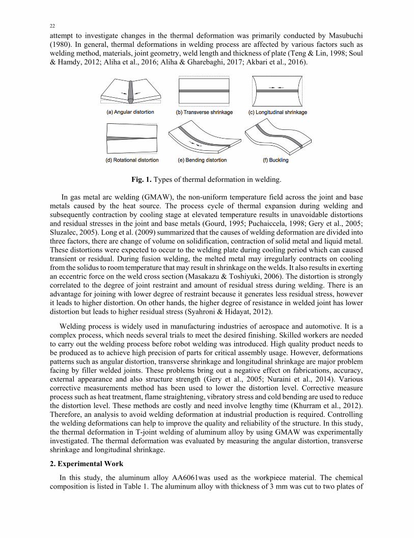
Thermal deformation is an unavoidable effect that might influence the accuracy of assembly and external appearance of the weld joint. It occurred due to local thermal cycle during welding that response to a change temperature through heat transfer and can be temporary or residual. In a few decades, the attention in using aluminum greatly has increased as a structural material. However, the distortion issues in welding aluminum are much more severe than those of steel, since it has volume shrinkage as large as 6% (Li et al., 2009). Research studies had identified thermal deformation and classified into six types; angular distortion, longitudinal shrinkage, transverse shrinkage, longitudinal bending distortion, buckling distortion and rotational distortion (Radaj, 1992; Liang & Hidekazu, 2012). Fig. 1 shows the type of thermal deformation in welding process. The inherent deformations are mainly determined by welding input, the thickness of material and type of welding joint. The initial
22
attempt to investigate changes in the thermal deformation was primarily conducted by Masubuchi (1980). In general, thermal deformations in welding process are affected by various factors such as welding method, materials, joint geometry, weld length and thickness of plate (Teng & Lin, 1998; Soul & Hamdy, 2012; Aliha et al., 2016; Aliha & Gharebaghi, 2017; Akbari et al., 2016).
Fig. 1. Types of thermal deformation in welding. In gas metal arc welding (GMAW), the non-uniform temperature field across the joint and base metals caused by the heat source. The process cycle of thermal expansion during welding and subsequently contraction by cooling stage at elevated temperature results in unavoidable distortions and residual stresses in the joint and base metals (Gourd, 1995; Puchaiccela, 1998; Gery et al., 2005; Sluzalec, 2005). Long et al. (2009) summarized that the causes of welding deformation are divided into three factors, there are change of volume on solidification, contraction of solid metal and liquid metal. These distortions were expected to occur to the welding plate during cooling period which can caused transient or residual. During fusion welding, the melted metal may irregularly contracts on cooling from the solidus to room temperature that may result in shrinkage on the welds. It also results in exerting an eccentric force on the weld cross section (Masakazu & Toshiyuki, 2006). The distortion is strongly correlated to the degree of joint restraint and amount of residual stress during welding. There is an advantage for joining with lower degree of restraint because it generates less residual stress, however it leads to higher distortion. On other hands, the higher degree of resistance in welded joint has lower distortion but leads to higher residual stress (Syahroni & Hidayat, 2012).
Welding process is widely used in manufacturing industries of aerospace and automotive. It is a complex process, which needs several trials to meet the desired finishing. Skilled workers are needed to carry out the welding process before robot welding was introduced. High quality product needs to be produced as to achieve high precision of parts for critical assembly usage. However, deformations patterns such as angular distortion, transverse shrinkage and longitudinal shrinkage are major problem facing by filler welded joints. These problems bring out a negative effect on fabrications, accuracy, external appearance and also structure strength (Gery et al., 2005; Nuraini et al., 2014). Various corrective measurements method has been used to lower the distortion level. Corrective measure process such as heat treatment, flame straightening, vibratory stress and cold bending are used to reduce the distortion level. These methods are costly and need involve lengthy time (Khurram et al., 2012). Therefore, an analysis to avoid welding deformation at industrial production is required. Controlling the welding deformations can help to improve the quality and reliability of the structure. In this study, the thermal deformation in T-joint welding of aluminum alloy by using GMAW was experimentally investigated. The thermal deformation was evaluated by measuring the angular distortion, transverse shrinkage and longitudinal shrinkage.
2. Experimental Work
In this study, the aluminum alloy AA6061was used as the workpiece material. The chemical composition is listed in Table 1. The aluminum alloy with thickness of 3 mm was cut to two plates of

M. I. S. Ismail et al. / Engineering Solid Mechanics 6 (2018)
23
125mm x 125mm for the flange plate and 125mm x 30mm for the web plate. The T-joint or double filler weld design was welded as shown in Fig. 2. The welding experiments were conducted with a motorized translations stage to perform the consistent and steady welding speed. The GMAW process was executed by KempoWeld machine with 1mm aluminum wire electrode under inert gas of argon as shielding gas. The orientation of welding torch was aligned 45 degree to the perpendicular axis of workpiece surface. Table 1. Chemical composition of aluminum alloy AA6061 (wt.%).
Al Cu Fe Mg Mn Si Ti ZnBal. 0.15 ≤0.7 0.8-1.2 0.15 0.4-0.8 0.15 0.25
Table 2. Welding condition.
Parameter Value Welding speed (mm/s) 20, 30, 40 Welding voltage (V) 18, 20, 22 Welding current (A) 140 Flow rate (l/min) 18 Shielding gas Argon Wire electrode feed rate (mm/s) 148 Wire electrode diameter (mm) 1
Fig. 2. Experimental setup of GMAW process. Welding experiments were carried out according to welding condition as shown in Table 2. Total of 9 experiments were conducted by varying the welding speed and welding voltage. Wire electrode feed rate, flow rate of shielding gas and welding current remained constant in the welding experiment. The angular distortion was measured using a dial gauge.
24
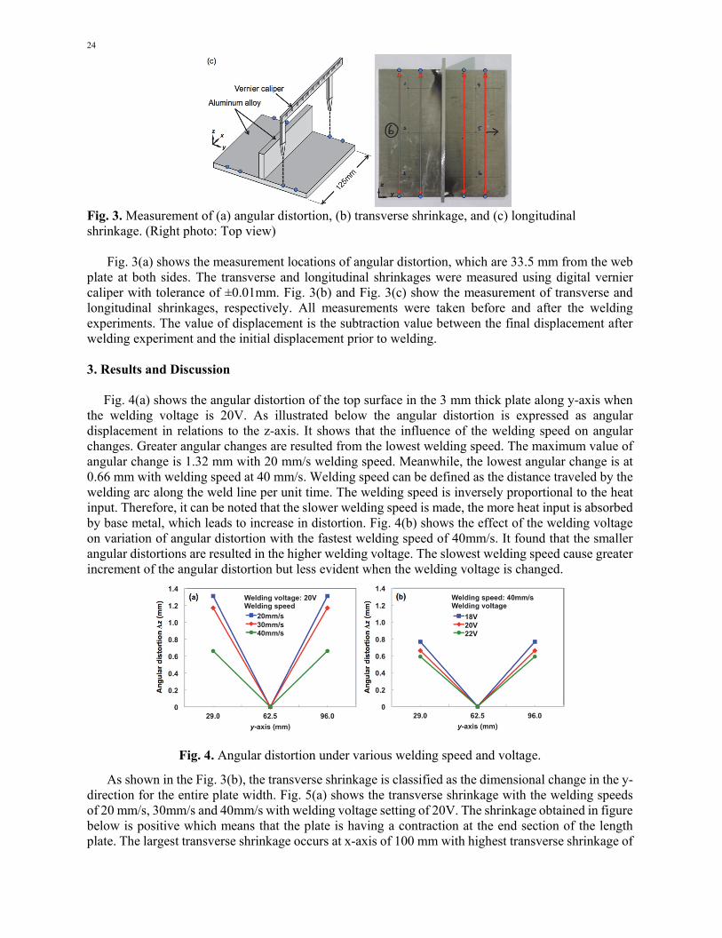
Fig. 3. Measurement of (a) angular distortion, (b) transverse shrinkage, and (c) longitudinal shrinkage. (Right photo: Top view)
Fig. 3(a) shows the measurement locations of angular distortion, which are 33.5 mm from the web plate at both sides. The transverse and longitudinal shrinkages were measured using digital vernier caliper with tolerance of ±0.01mm. Fig. 3(b) and Fig. 3(c) show the measurement of transverse and longitudinal shrinkages, respectively. All measurements were taken before and after the welding experiments. The value of displacement is the subtraction value between the final displacement after welding experiment and the initial displacement prior to welding. 3. Results and Discussion
Fig. 4(a) shows the angular distortion of the top surface in the 3 mm thick plate along y-axis when the welding voltage is 20V. As illustrated below the angular distortion is expressed as angular displacement in relations to the z-axis. It shows that the influence of the welding speed on angular changes. Greater angular changes are resulted from the lowest welding speed. The maximum value of angular change is 1.32 mm with 20 mm/s welding speed. Meanwhile, the lowest angular change is at 0.66 mm with welding speed at 40 mm/s. Welding speed can be defined as the distance traveled by the welding arc along the weld line per unit time. The welding speed is inversely proportional to the heat input. Therefore, it can be noted that the slower welding speed is made, the more heat input is absorbed by base metal, which leads to increase in distortion. Fig. 4(b) shows the effect of the welding voltage on variation of angular distortion with the fastest welding speed of 40mm/s. It found that the smaller angular distortions are resulted in the higher welding voltage. The slowest welding speed cause greater increment of the angular distortion but less evident when the welding voltage is changed.
Fig. 4. Angular distortion under various welding speed and voltage.
As shown in the Fig. 3(b), the transverse shrinkage is classified as the dimensional change in the y-direction for the entire plate width. Fig. 5(a) shows the transverse shrinkage with the welding speeds of 20 mm/s, 30mm/s and 40mm/s with welding voltage setting of 20V. The shrinkage obtained in figure below is positive which means that the plate is having a contraction at the end section of the length plate. The largest transverse shrinkage occurs at x-axis of 100 mm with highest transverse shrinkage of

M. I. S. Ismail et al. / Engineering Solid Mechanics 6 (2018)
25
1.22 mm. The transverse shrinkage is low at the starting of welding line. It can be noticed that the end of the plate has the highest transverse thermal contraction due to the greater heat transfer along the longitudinal direction at starting point. Slowest welding speed caused the highest transverse shrinkage in the plate as can be seen when the welding speed is 20mm/s. When the welding speed is increase, the transverse shrinkage is reduced gradually. It may causes by lower heat energy input during the welding process when a faster welding speed is applied. Transverse shrinkage in low welding voltage is much smaller than higher welding voltage as illustrated in Fig. 5(b). This is due to decreased heat input by the arc which results in faster cooling rate. It also can be observed that the transverse shrinkage with low welding voltage is almost symmetrical along the plate width (y-axis).
Fig. 5. Transverse shrinkage under various welding speed and voltage.
Fig. 6 shows longitudinal shrinkage along x-direction. The longitudinal shrinkage is defined as the dimensional change in the x-direction as shown in Fig. 3(c). The results show that longitudinal shrinkage near the weld bead is larger than at the two sides of welding specimens. It means that the longitudinal shrinkage is notably happening in the weld zone and small longitudinal shrinkage produced far away from weld bead. From Fig. 6(a), there is significant increase of the longitudinal shrinkage when a slower welding speed is performed. It is a result of higher heat input was generated during the welding process. However, the longitudinal shrinkage is less significant affected by changing the welding heat input. It also has been found that the longitudinal shrinkage tends to become small with the low welding voltage as shown in Fig. 6(b). In general, concave deformation is produced even if the welding voltage and speed are changed. It also can be noticed that the longitudinal shrinkage is less sensitive as compared to other directional displacements.
Fig. 6. Longitudinal shrinkage under various welding speed and voltage.
4. Conclusion
The welding deformation on T-joint welding of aluminum alloy by using gas metal arc welding process was experimentally investigated. Welding speed and voltage have a significant impact in welding deformation. The angular distortion appeared as V-shaped and it decreases with the shorter welding interaction time and higher heat input. The transverse shrinkage is increasing with decreasing of welding speed and increasing of welding voltage. The plate is having a contraction at the end section

26
of the width plate. The transverse shrinkage is largely influenced by the welding heat input. The longitudinal shrinkage is larger with low welding speed and high welding voltage. The longitudinal shrinkage is much smaller compare to angular distortion and transverse shrinkage. The concave deformation is produced even if the welding voltage and speed are changed. These findings could be useful for improvement the welding deformation in manufacturing industries.
Acknowledgements
The authors would like to acknowledge the technical support provided by Mr. Ahmad Shaifudin Ismail and Mr. Mohd Saiful Azuar Md. Isa in carrying out the experimental work at the Faculty of Engineering, Universiti Putra Malaysia (UPM).
References
Akbari, M., Aliha, M. R. M., Keshavarz, S. M. E., & Bonyadi, A. (2016). Effect of tool parameters on mechanical properties, temperature, and force generation during FSW. Proceedings of the Institution of Mechanical Engineers, Part L: Journal of Materials: Design and Applications, 1464420716681591.
Aliha, M. R. M., & Gharehbaghi, H. (2017). The Effect of Combined Mechanical Load/Welding Residual Stress on Mixed Mode Fracture Parameters of a Thin Aluminum Cracked Cylinder. Engineering Fracture Mechanics.
Aliha, M. R. M., Shahheidari, M., Bisadi, M., Akbari, M., & Hossain, S. (2016). Mechanical and metallurgical properties of dissimilar AA6061-T6 and AA7277-T6 joint made by FSW technique. The International Journal of Advanced Manufacturing Technology, 86(9-12), 2551-2565.
Gery, D., Long, H., & Maropoulos, P. (2005). Effects of welding speed, energy input and heat source distribution on temperature variations in butt joint welding. Journal of Materials Processing Technology, 167(2-3), 393-401.
Gourd, L.M. (1995). Principles of welding technology. Oxford: Butterworth-Heinemann. Khurram, A., Hong, L., Li, L., & Shehzad, S. (2012). Prediction of welding deformation and residual stresses in
fillet welds using indirect couple field FE method. Research Journal of Applied Sciences, Engineering and Technology, 5(10), 2934-2940.
Li, J., Yang, J.G., Li, H.L., Yan, D.J., & Fang, H.Y. (2009). Numerical simulation on buckling distortion of aluminum alloy thin-plate weldment. Frontiers of Material Science. 3(1), 84-88.
Liang, W., & Hidekazu, M. (2012). An inverse analysis method to estimate inherent deformations in thin plate welded joints. Materials and Design. 40, 190-198.
Long, H., Gery, D., Carlier, A., & Maropoulos, P.G. (2009). Prediction of welding distortion in butt joint of thin plates. Materials and Design. 30(10), 4126-4135.
Masakazu, T., & Toshiyuki, O. (2006). Weld distortion. Kobelco Welding Today, 9(3), 8. Masubuchi, K. (1980). Analysis of welded structures: Residual stresses, distortion, and their consequences.
London: Pergamon Press. Nuraini, A.A., Zainal, A.S., & Azmah Hanim, M.A. (2014). The effects of welding parameters on butt joints
using robotic gas metal arc welding. Journal of Mechanical Engineering and Sciences. 6, 988-994. Puchaccela, J. (1998). Control of distortion of welded steel structures. Welding Journal. 77, 49-52. Radaj, D. (1992). Heat effects of welding: Temperature field, residual stress, distortion. Berlin: Spinger-Verlag. Sluzalec, A. (2005). Theory of thermomechanical processes in welding. Dordrecht: Springer. Soul, F., & Hamdy, N. (2012). Numerical simulation of residual stress and strain behavior after temperature
modification, in: Kovacevic, R. (Ed.), Welding Processes. InTech, pp. 217-246. Syahroni, N., & Hidayat, M.I.P. (2012). 3D finite element simulation of T-joint fillet weld: Effect of various
welding sequences on the residual stresses and distortions, in: Andriychuk, M. (Ed.), Numerical Simulation – From Theory to Industry. InTech, pp. 583-606.
Teng, T.L., & Lin, C.C. (1998). Effect of welding conditions on residual stress due to butt welds. International Journal of Pressure Vessels and Piping. 75, 857-864.
© 2018 by the authors; licensee Growing Science, Canada. This is an open access article distributed under the terms and conditions of the Creative Commons Attribution (CC-BY) license (http://creativecommons.org/licenses/by/4.0/).