thermal analysis of spent lwr fuel casks under normal and accident conditions miles greiner...
TRANSCRIPT

Thermal Analysis of Spent LWR Fuel Casks Under Normal and Accident
Conditions
Miles GreinerUniversity of Nevada, Reno
Systems Analysis Technical Guidance fromBill Halsey, LLNL
GNEP Annual Meeting, October 1, 2007Litchfield Park, AZ

Spent LWR Fuel Casks
• Spent fuel is placed in thick-wall, gas-filled casks for storage and transport
• Individual assemblies are supported in a basket• Designed to provide protection under accident
and normal conditions
Storage Packages
Internal Structure
Rail Cask

Container Analysis Fire Environment (CAFE) CFD code
• Under development at Sandia to predict cask response in large fires for risk studies
• Employs physics-based models that allow it to accurately calculate heat transfer from large fires to objects even when coarse grids are employed
• Parameters of the models must be determined from large-fire experiments

Ongoing Work
• July-September, 2007, performed three fire tests with a rail-cask-sized calorimeter.– Measured calorimeter temperature and wind conditions
• Currently performing CAFE simulations using the measured wind as boundary conditions
• Determining model parameters that bring simulation results close to data
0
200
400
600
800
0 500 1000 1500 2000
Time (s)
DT
(K
)
Experiment
CAFE(Initial
Simulation)
Measured and Simulated Average TemperatureCAFE Fire
SimulationRail-Cask-Size Pipe Calorimeter in a JP8 Fire

Normal Conditions 38ºC still air, full solar heat flux
• Fuel generates heat but its cladding must not exceed 400ºC– Affects the amount of time the fuel must be aged, and/or – Limits number of assemblies that can be loaded (cask capacity)
• In the past – Computer resources were not available to accurately model the fuel rod
geometry – In Full Cross section models, the fuel was replaced by solids with an
Effective Thermal Conductivity (ETC) that conservatively overestimate clad temperatures

200
300
400
500
200 300 400 500 600 700 800Q [W/Assembly]
T [0C] ETCCFD
4000C
Current Work• Whole Rail Cask Cross Section Simulations, including
– Accurate fuel rod geometry– CFD simulations of gas motion (using Fluent®)
• Calculate Peak Clad Temperature vs Fuel Heat Generation Rate• Current CFD simulations predict lower cladding temperatures than ETC
model, and higher cask thermal dissipation capacity– Are three-dimensional effects important?– Vertical configuration requires three-dimensional simulations
¼ of Full Cross-sectionIncluding Fuel
Cover Gas Streamlines
Peak Clad Temperature vs Assembly Heat Generation
Rate

3D CFD Fuel Assembly Simulations Model Region Between Consecutive Spacer Plates
• Compare two- and three-dimensional CFD simulations results
• Are these results quantitatively accurate?
PWR Assembly
Vertical (Storage) Orientation
Horizontal (Transport) Orientation
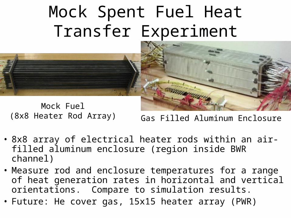
Mock Spent Fuel Heat Transfer Experiment
• 8x8 array of electrical heater rods within an air-filled aluminum enclosure (region inside BWR channel)
• Measure rod and enclosure temperatures for a range of heat generation rates in horizontal and vertical orientations. Compare to simulation results.
• Future: He cover gas, 15x15 heater array (PWR)
Mock Fuel(8x8 Heater Rod Array) Gas Filled Aluminum Enclosure
Status• 15 months through a 24 month program• Benchmarking simulation tools to predict the
performance of LWR casks under normal and fire accident conditions
• Developing expertise that will be applied to AFCI packages, once they have been designed
• We are looking for guidance on ways to apply our thermal analysis capabilities to new areas that are central to AFCI development – We have congressional funding
