thermal analysis of a in line 4-cylinder engine 62 thermal analysis of a in line 4-cylinder engine...
TRANSCRIPT
Page 62
Thermal Analysis of a in Line 4-Cylinder Engine
Bidla Rohit
Malla Reddy College of Engineering,
Maisammaguda, Dhulapally,
Telangana, India.
Smt.Dr.V.Vprathiba Bharathi
Malla Reddy College of Engineering,
Maisammaguda, Dhulapally,
Telangana, India.
ABSTRACT:
The inline-four cylinder engine or straight four
engine is an inside combustion engine with all four
cylinders mounted in an exceedingly line, or plane on
the housing. The one bank of cylinders could also be
familiarized in either a vertical or associate degree
simple machine with all the pistons driving a typical
shaft. Wherever it's inclined, it's generally known as
a slant-four. Specification chart or once an
abbreviation is employed, associate degree in line
four engine is listed either as I4 or L4.
The most objective of the project is a way to develop
the piston, crankshaft and connecting rod USING
CAD tool PRO/ENGINEER. This Engine assembly
consists major elements they're Piston, rod Assembly,
Crank Shaft, plate, Cam Shaft, Valves, crank case,
oil tank and electrical device.
The elements that area unit developed in
PRO/ENGINEER are analyzed in ANSYS simulation
tool. The thermal analysis of piston, connecting rod
and crank shaft is performed for 500, 450, 380oc
thermal loading and therefore the results of
temperature distribution of the elements are shown.
Finally the thermal analysis results of the elements
area unit compared and therefore the best suited
material is chosen.
I. INTRODUCTION
Inline Four Engine
The inline-four engine or straight-four engine is a type
of inline internal combustion four cylinder engine with
all four cylinders mounted in a straight line, or plane
along the crankcase. The single bank of cylinders may
be oriented in either a vertical or an inclined plane
with all the pistons driving a common crankshaft.
Where it is inclined, it is sometimes called a slant-four.
In a specification chart or when an abbreviation is
used, an inline-four engine is listed either
as I4 or L4 (for longitudinal, to avoid confusion
between the digit 1 and the letter I).
The inline-four layout is in perfect primary
balance and confers a degree of mechanical simplicity
which makes it popular for economy cars. However,
despite its simplicity, it suffers from a secondary
imbalance which causes minor vibrations in smaller
engines. These vibrations become more powerful as
engine size and power increase, so the more powerful
engines used in larger cars generally are more
complexdesigns with more than four cylinders.
Today almost all manufacturers of four-cylinder
engines for automobiles produce the inline-four layout,
with Subaru's flat-four engine being a notable
exception, and so four-cylinder is synonymous with
and a more widely used term than inline-four. The
inline-four is the most common engine configuration
in modern cars, while the V6 engine isthe second most
popular. In the late 2000s, with automanufacturers
making efforts to reduce emissions and increase fuel
efficiency due to the high price of oil and
the economic recession, the proportion of new vehicles
sold in the U.S. with four-cylinder engines (largely of
the inline-four type) rose from 30 percent to 47 percent
between 2005 and 2008, particularly in mid-size
vehicles where a decreasing number of buyers have
chosen the V6 performance option.
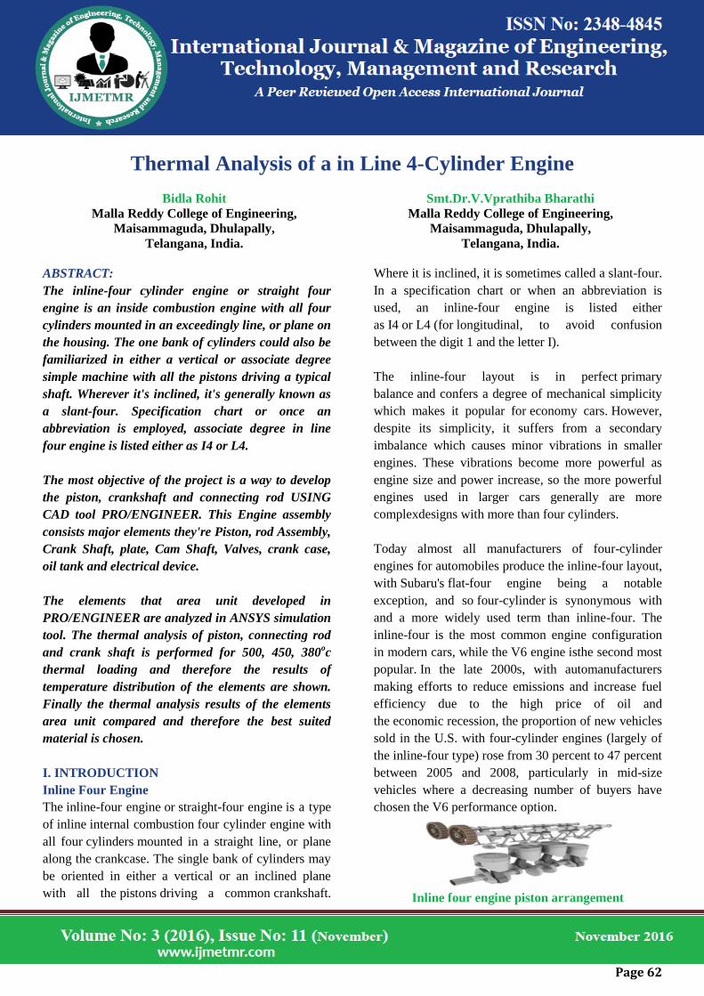
Inline four engine piston arrangement

Page 63
Cylinder
A cylinder is the central working part of
a reciprocating engine or pump, the space in which
a piston travels. Multiple cylinders are commonly
arranged side by side in a bank, or engine block, which
istypically cast from aluminum or cast iron before
receiving precisionwork. Cylinders may
be sleeved (lined with a harder metal)
or sleeveless (with a wear-resistant coating such
as Nikasil). A sleeveless engine may also be referred
to as a "patent-bore engine"machine
Cylinder block
A cylinder's displacement, or swept volume, can be
calculated by multiplying its cross-
sectional area (the square of half the bore by pi) by the
distance the piston travels within the cylinder
(the stroke). The engine displacement can be
calculated by multiplying the swept volume of one
cylinder by the number of cylinders.
Piston
A piston is seated inside each cylinder by several
metal piston rings fitted around its outside surface in
machined grooves; typically two
for compressional sealing and one to seal the oil. The
rings make near contact with the cylinder walls
(sleeved or sleeveless), riding on a thinlayer of
lubricating oil; essential to keep the engine from
seizing and necessitating a cylinder wall's durable
surface.
Piston head
During the earliest stage of an engine's life, its
initial breaking-in or running-in period, small
irregularities in the metals are encouraged to gradually
form congruent grooves by avoiding extreme operating
conditions. Later in its life, after mechanical wear has
increased the spacing between the piston and the
cylinder (with a consequent decrease in power output)
the cylinders may be machined to a slightly larger
diameter to receive new sleeves (where applicable) and
piston rings, a process sometimes known as reboring.
Connecting rod
In a reciprocating piston engine, the connecting rod or
conrod connects the piston to the crank or crankshaft.
Together with the crank, they form a simple
mechanism that converts reciprocating motion into
rotating motion. Connecting rods may also convert
rotating motion into reciprocating motion. Historically,
before the development of engines, they were first
used in this way.
Connecting rod
As a connecting rod is rigid, it may transmit either a
push or a pull and so the rod may rotate the crank
through both halves of a revolution, i.e. piston pushing
and piston pulling. Earlier mechanisms, such as chains,
could only pull. In a few two-stroke engines, the
connecting rod is only required to push. Today,
connecting rods are best known through their use in
internal combustion piston engines, such as automotive
engines. These are of a distinctly different design from
earlier forms of connecting rods, used in steam engines
and steam locomotives.
Crankshaft
A crankshaft is a mechanical part able to perform a
conversion between reciprocating motion and
rotational motion. In a reciprocating engine, it
translates reciprocating motion of the piston into
Page 64
rotational motion; whereas in a reciprocating
compressor, it converts the rotational motion
intoreciprocating motion. In order to do the conversion
between two motions, the crankshaft has "crank
throws" or "crankpins", additional bearing surfaces
whose axis is offset from that of the crank, to which
the "big ends" of the connecting rods from each
cylinder attach.
Crankshaft
It is typically connected to a flywheel to reduce the
pulsation characteristic of the four-stroke cycle, and
sometimes a torsional or vibrational damper at the
opposite end, to reduce the torsional vibrations often
caused along the length of the crankshaft by the
cylinders farthest from the output end acting on the
torsional elasticity of the metal.
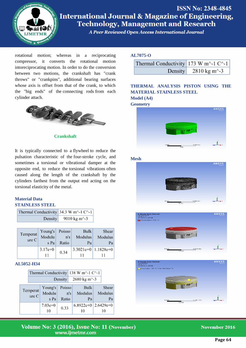
Material Data
STAINLESS STEEL
AL5052-H34
AL7075-O
THERMAL ANALYSIS PISTON USING THE
MATERIAL STAINLESS STEEL
Model (A4)
Geometry
Mesh

Page 65
TEMPERATURE
TOTAL HEAT FLUX
DIRECTIONAL HEAT FLUX
THERMAL ERROR
THERMAL ANALYSIS PISTON USING THE
MATERIAL AL 5052
TEMPERATURE
TOTAL HEAT FLUX
DIRECTIONAL HEAT FLUX

Page 66
THERMAL ERROR
THERMAL ANALYSIS PISTON USING THE
MATERIAL AL 7075
TEMPERATURE
TOTAL HEAT FLUX
DIRECTIONAL HEAT FLUX
THERMAL ERROR
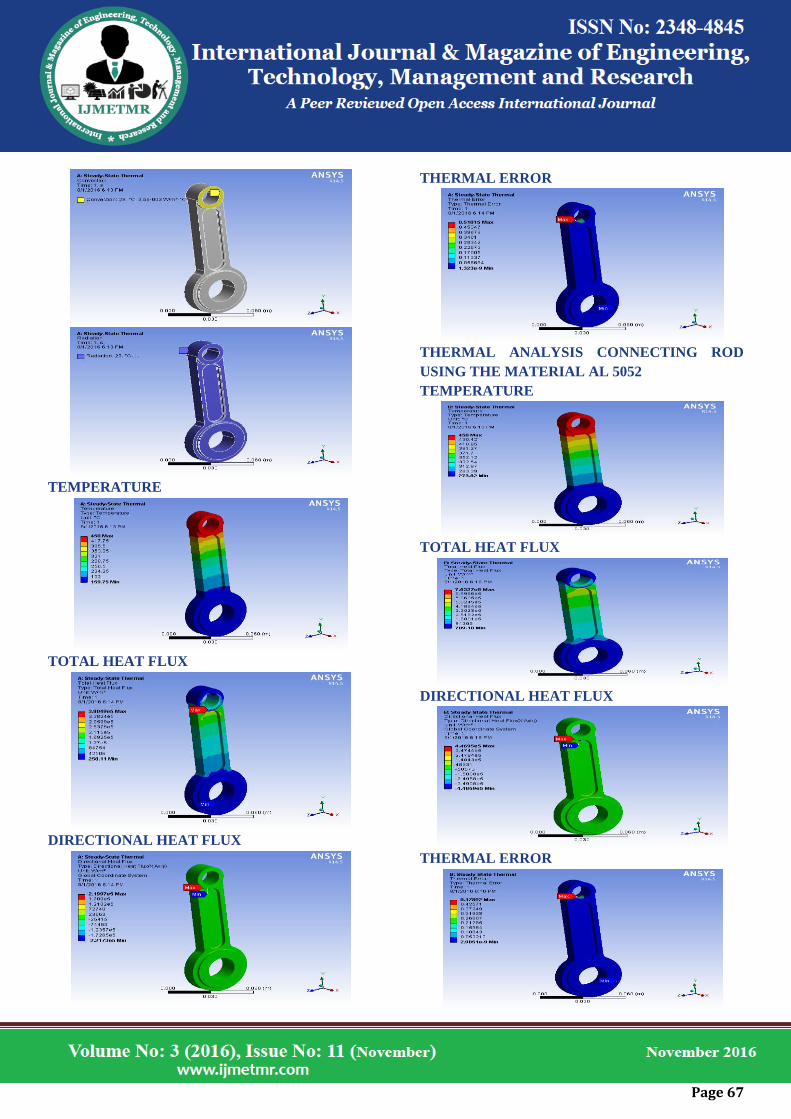
THERMAL ANALYSIS CONNECTING ROD
USING THE MATERIAL STAINLESS STEEL
Model (A4)
Geometry
Mesh
Page 67
TEMPERATURE
TOTAL HEAT FLUX
DIRECTIONAL HEAT FLUX
THERMAL ERROR
THERMAL ANALYSIS CONNECTING ROD
USING THE MATERIAL AL 5052
TEMPERATURE
TOTAL HEAT FLUX
DIRECTIONAL HEAT FLUX
THERMAL ERROR
Page 68
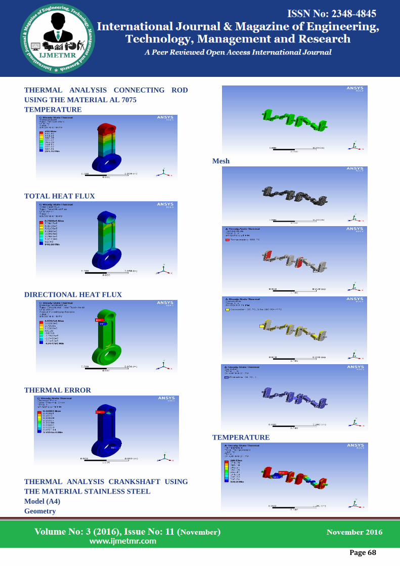
THERMAL ANALYSIS CONNECTING ROD
USING THE MATERIAL AL 7075
TEMPERATURE
TOTAL HEAT FLUX
DIRECTIONAL HEAT FLUX
THERMAL ERROR
THERMAL ANALYSIS CRANKSHAFT USING
THE MATERIAL STAINLESS STEEL
Model (A4)
Geometry
Mesh
TEMPERATURE

Page 69
TOTAL HEAT FLUX
DIRECTIONAL HEAT FLUX
THERMAL ERROR
THERMAL ANALYSIS CRANKSHAFT USING
THE MATERIAL AL 5052
TEMPERATURE
TOTAL HEAT FLUX
DIRECTIONAL HEAT FLUX
THERMAL ERROR
THERMAL ANALYSIS CRANKSHAFT USING
THE MATERIAL AL 7075
TEMPERATURE
Page 70
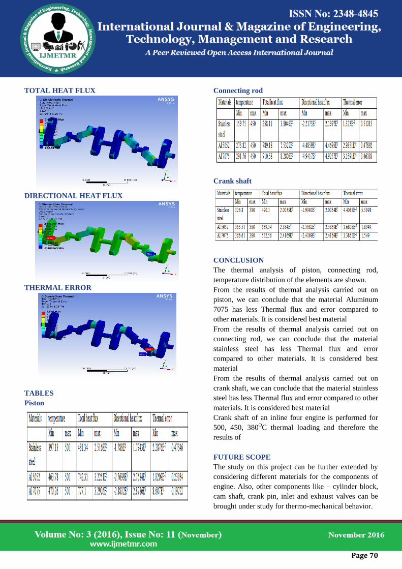
TOTAL HEAT FLUX
DIRECTIONAL HEAT FLUX
THERMAL ERROR
TABLES
Piston
Connecting rod
Crank shaft
CONCLUSION
The thermal analysis of piston, connecting rod,
temperature distribution of the elements are shown.
From the results of thermal analysis carried out on
piston, we can conclude that the material Aluminum
7075 has less Thermal flux and error compared to
other materials. It is considered best material
From the results of thermal analysis carried out on
connecting rod, we can conclude that the material
stainless steel has less Thermal flux and error
compared to other materials. It is considered best
material
From the results of thermal analysis carried out on
crank shaft, we can conclude that the material stainless
steel has less Thermal flux and error compared to other
materials. It is considered best material
Crank shaft of an inline four engine is performed for
500, 450, 380OC thermal loading and therefore the
results of
FUTURE SCOPE
The study on this project can be further extended by
considering different materials for the components of
engine. Also, other components like – cylinder block,
cam shaft, crank pin, inlet and exhaust valves can be
brought under study for thermo-mechanical behavior.
Page 71
References
1. The 4-Cylinder Engine Short Block High-
Performance Manual: Updated and Revised
New Des Hammill, Veloce Publishing Ltd, 01-
Jan-2012
2. Automotive Engines, S Srinivasan, Tata
McGraw-Hill Education
3. Classroom Manual for Automotive Engine
Performance, Douglas Vidler, Cengage
Learning, 2003
4. Modeling and analysis of an HCCI engine
during thermal transients using a
thermodynamic cycle simulation with a
coupled wall thermal network, Kyoungjoon
Chang, University of Michigan, 2007
5. Thermomechanical Fatigue Behavior of
Materials: Fourth volume, Issue 1428, Michael
A. McGaw, ASTM International, 01-Jan-2003
Author Details
Bidla Rohit received the B.Tech degree in mechanical
engineering from ChilkurBalaji Institute of
Technology, Aziz Nagar, moinabad, Telangana, India,
in 2014 year, and perusing M.Tech in THERMAL
ENGINEERING from Malla Reddy College of
Engineering , Maisammaguda Dhulapally, Telangana,
India.
Smt.Dr.V.Vprathiba Bharathi, M.Tech Ph.D,
Professor, Malla Reddy College of Engineering
Maisammaguda, Dhulapally, Telangana, India.