there are no trifles in well casing! · - top as per gost 633-80 - bottom as per gost 633-80 60 60...
TRANSCRIPT


THERE ARE NO TRIFLES IN WELL CASING!

«WELL COMPLETION, OPERATION AND WORKOVER»
Since its foundation in 1998 “ZERS” has developed and introduced into production more than 400 technical products designed to improve the quality of well construction. These are complexes for productive beds isolation, external and internal casing packers for various applications, stage and collar cementing sleeves, liner hangers, multi-stage fracturing completions, check valves, centralizers, well screen and other casing hardware.
As of January 1, 2018, we have provided services with our equipment at more than 7778 wells and run in wells more than 210 thousand “ZERS”-manufactured tools.
Significant experience in new equipment design together with thorough analysis of its field applications allowed us to develop and patent many new generation devices. Responsibility for the production quality, flexible terms of manufacturing and independent commercial strategy led us to investing into our own manufacturing facilities. This allows “ZERS” to control the equipment lifecycle from design to commissioning, and helps in achieving better results every year.

CONTENTSCertificates and Licenses . . . . . . . . . . . . . . . . . . . . . . . . . . . . . . . . . . . . . . .
I. LINER HANGERS
Noncemented Retrievable Liner Hanger PHN-E . . . . . . . . . . . . . . . . . . . . . . .Noncemented Liner Hanger PHN1 . . . . . . . . . . . . . . . . . . . . . . . . . . . . . . . . .Noncemented Liner Hanger PHN2 . . . . . . . . . . . . . . . . . . . . . . . . . . . . . . . .Noncemented Liner Hanger rotating while running in PHNV . . . . . . . . . . . . . .Noncemented Liner Hanger with oriented wedge PHN-KO . . . . . . . . . . . . . . .Protected Cemented Liner Hanger PHCZ . . . . . . . . . . . . . . . . . . . . . . . . . . . .Protected Rotated Cemented Liner Hanger PHCZV . . . . . . . . . . . . . . . . . . . . .Hydro-Mechanical Cemented Liner Hanger PHGMC . . . . . . . . . . . . . . . . . . .Protected Hydro-Mechanical Cemented Liner Hanger PHGMCZ . . . . . . . . . . .Liner Hanger with disconnection before cementing PHRC . . . . . . . . . . . . . . . .Cemented Liner Hanger for flush-joint pipes PHCBT . . . . . . . . . . . . . . . . . . . .Protected Liner Hanger for stage cementing PHZSC . . . . . . . . . . . . . . . . . . . .
II. PACKERS
Protected Hydraulic Packer PGRPZ . . . . . . . . . . . . . . . . . . . . . . . . . . . . . . . .Hydraulic Full-Bore Packer PGP, PGP1, PGP6 . . . . . . . . . . . . . . . . . . . . . . . . .Cross-flow Sealing Packer PGMP . . . . . . . . . . . . . . . . . . . . . . . . . . . . . . . . .Hydraulic Full-Bore Packer with Small-Size Valve Unit PGPM1.245 . . . . . . . . . .Hydraulic Packer for Collar Cementing PGMC, PGMC2, PGMC4, PGMC6 . . .Collar Cementing Packer PMC, PMC-R . . . . . . . . . . . . . . . . . . . . . . . . . . . . .Water-Swellable and Oil-Swellable Packer PNV and PNN . . . . . . . . . . . . . . . .
III. EXTERNAL CASING ATTACHMENTS
Collar for Collar Cementing MMC1 . . . . . . . . . . . . . . . . . . . . . . . . . . . . . . . .String Disconnect for Water Wells RKVS . . . . . . . . . . . . . . . . . . . . . . . . . . . . .Multiple-Unit Rotating Disconnect RKVO . . . . . . . . . . . . . . . . . . . . . . . . . . . . .Collar Cementing Valve KMC . . . . . . . . . . . . . . . . . . . . . . . . . . . . . . . . . . . .Cementing Basket CK . . . . . . . . . . . . . . . . . . . . . . . . . . . . . . . . . . . . . . . . . .Pressure Test Device PO . . . . . . . . . . . . . . . . . . . . . . . . . . . . . . . . . . . . . . . .Stage-by-stage Casing Running Tool USSK, USSKP . . . . . . . . . . . . . . . . . . . . .Hydraulic Fracturing Sealing Assembly UGRH . . . . . . . . . . . . . . . . . . . . . . . . .Screener UECS . . . . . . . . . . . . . . . . . . . . . . . . . . . . . . . . . . . . . . . . . . . . . .Ball Check Valve KOSH2, KOSHBT . . . . . . . . . . . . . . . . . . . . . . . . . . . . . . . .Seat-Trap SL . . . . . . . . . . . . . . . . . . . . . . . . . . . . . . . . . . . . . . . . . . . . . . . . .Auxiliary Top Modular Packer PDV-M . . . . . . . . . . . . . . . . . . . . . . . . . . . . . . .Top Auxiliary Packer PDV2 . . . . . . . . . . . . . . . . . . . . . . . . . . . . . . . . . . . . . .Trip Stop-Tap CPD2 . . . . . . . . . . . . . . . . . . . . . . . . . . . . . . . . . . . . . . . . . . .Bow-Spring Centralizer PC . . . . . . . . . . . . . . . . . . . . . . . . . . . . . . . . . . . . . .
5
81013161820242833364042
46474950525557
626466686970727476777980818384

Hard Elastic Centralizer PCR . . . . . . . . . . . . . . . . . . . . . . . . . . . . . . . . . . . . .Low-frictional Turbulence Generating Centralizer CTN . . . . . . . . . . . . . . . . . . .Stop Ring SKC . . . . . . . . . . . . . . . . . . . . . . . . . . . . . . . . . . . . . . . . . . . . . . .Cementing Throttle Check Valve CKOD . . . . . . . . . . . . . . . . . . . . . . . . . . . . .Casing Shoe BK . . . . . . . . . . . . . . . . . . . . . . . . . . . . . . . . . . . . . . . . . . . . . .Well Screen FS, FB . . . . . . . . . . . . . . . . . . . . . . . . . . . . . . . . . . . . . . . . . . . .
IV. DRILLING EQUIPMENT
Selective Washing Device for Wells USPS . . . . . . . . . . . . . . . . . . . . . . . . . . . .
V. HYDRAULIC FRACTURING
Technical Equipment Set for a Liner Well Casing with the following Multistage Hydraulic Fracturing . . . . . . . . . . . . . . . . . . . . . .Check Valve KO . . . . . . . . . . . . . . . . . . . . . . . . . . . . . . . . . . . . . . . . . . . . . .Hydraulic Packer for Hydraulic Fracturing PGRP . . . . . . . . . . . . . . . . . . . . . . .Water and Oil Swellable Packer for Hydraulic Fracturing . . . . . . . . . . . . . . . . .Staged Hydraulic Fracturing Collar MSGRP and MSGRP-G . . . . . . . . . . . . . . .Closing Frac Port FPZ and FPZ-GCollar for Collar Cementing Sleeve for Hydraulic Fracturing MMC-G . . . . . . . .Set of Equipment for Multistage Hydraulic Fracturing with Unlimited Number of Ports and Possibility of the Second Hydraulic Fracturing or Opening/Closing of Ports . . . . . . . . . . .Collar for Staged Hydraulic Fracturing with an Operating Device MSGRP-U . . .
VI. EXAMPLES OF ASSEMBLIES APPLIED FOR DIFFERENT PURPOSES
Well Casing with Noncementing Liner . . . . . . . . . . . . . . . . . . . . . . . . . . . . . .Well Casing with Noncementing Liner with Washing through a Shoe with Zonal Isolation by Swellable Packers . . . . . . . . . . . . . . . .Well Casing with Noncementing Liner with Zonal Isolation by Inflatable Packers Well Casing with Cementing Liner with Continuous Cementing with Zonal Isolation by Inflatable Packers . . . . . . . . . . . . . . . . . . . . . . . . . . . .Well Casing with Collar Cementing Liner with Additional Isolation of Upper Zones by Inflatable Packers . . . . . . . . . . . . . . . . . . . . . . . . . . . . . . .Well Casing with Noncementing Liner with Packaging for MSHF and Zonal Isolation by Swellable Packers . . . . . . . . . . . . . . . . . . . . . . . . . . . .Well Casing with Collar Cementing Liner with Packaging for MSHF and Zonal Isolation by Swellable Packers . . . . . . . . . . . . . . . . . . . . . . . . . . . .Well Casing with Collar Cementing Liner with Packaging for MSHF and Zonal Isolation by Hydraulic Packers . . . . . . . . . . . . . . . . . . . . . . . . . . . .Well Casing with Collar Cementing Liner with Two-Stage Cementing . . . . . . . .Well Casing with Cementing Liner with Continuous Cementing Followed by Multistage Hydraulic Fracturing . . . . . . . . . . . . . . . . . . . . . . . . . . . . . . . . .
868788899093
102
106108109111112114115
117118
122
123124
125
126
127
128
129130
131


CERTIFICATESAND LICENSES
5

LINERHANGERS I
Noncemented Retrievable Liner Hanger PHN-E . . . . . . . . . . . . . . . . . .
Noncemented Liner Hanger PHN1 . . . . . . . . . . . . . . . . . . . . . . . . . . . .
Noncemented Liner Hanger PHN2 . . . . . . . . . . . . . . . . . . . . . . . . . . .
Noncemented Liner Hanger rotating while running in PHNV . . . . . . . . .
Noncemented Liner Hanger with oriented wedge PHN-KO . . . . . . . . . .
Protected Cemented Liner Hanger PHCZ . . . . . . . . . . . . . . . . . . . . . . .
Protected Rotated Cemented Liner Hanger PHCZV . . . . . . . . . . . . . . . .
Hydro-Mechanical Cemented Liner Hanger PHGMC . . . . . . . . . . . . . . .
Protected Hydro-Mechanical Cemented Liner Hanger PHGMCZ . . . . . .
Liner Hanger with disconnection before cementing PHRC . . . . . . . . . . .
Cemented Liner Hanger for flush-joint pipes PHCBT . . . . . . . . . . . . . . .
Protected Liner Hanger for stage cementing PHZSC . . . . . . . . . . . . . . .
81013161820242833364042

E-mail: [email protected]: www.zers.ru
Tel.: +7 (495) 632-21-94 +7 (495) 632-21-95
Fax: ext. 121
107078, Moscow, Novaya Basmannaya str., 14-1390025, Ryazan Region, Ryazan, Promyshlennaya str., 21629803, Tyumen Region, YNAD, Noyabrsk, industrial zone, pan. 4628600, Tyumen Region, KMAD-Yugra, Nijnevartovsk, Industrialnaya str., 29461042, Orenburg Region, Buzuluk, Pyatigorskaya str., 39a build664041, Irkutsk Region, Irkutsk, Sovetskaya str., 124-e, RVC 384944001
NONCEMENTED RETRIEVABLE LINER HANGER PHN-E
The PHN-E liner hanger is used to RIH and hang a small ID non-cemented liner, providing the possibility to retrieve the liner if required.
This PHN-E liner hanger consists of 2 parts:
- anchor to hang the liner assembly in the casing string;
- hydraulic disconnection that allows to RIH liner assembly, circulate, activate anchor by hydraulic pressure and, then, disconnect the drill string from PHN-E by applying hydraulic pressure.
To retrieve the liner assembly, the spear (special tool) is run and set inside the PHN-E. The overpool of 5 ton is then applied to release an anchor and start pulling the liner out.
8

107078, �. l%“*"=, 3�. m%"= a=“�=……= , . 14, “2!. 1390025, p ƒ=…“*= %K�., . p ƒ=…�, o!%/���……= 3�., �. 21629803, Š��…“*= %K�., “m`n, . m% K!�“*, C!%ƒ%…=, C=…. 4628600, Š��…“*= %K�., ul`n-~ !=, . m,›…�"=!2%"“*, 3�. h…�3“2!,=��…= , �. 29461042, n!�…K3! “*= %K�., . a3ƒ3�3*, o 2, %!“*= 3�., �. 39=664041, h!*32“*= %K�., . h!*32“*, 3�. q%"�2“*= , �. 124-e, joo 384944001
E-mail: [email protected]: www.zers.ru
Š��.: +7 (495) 632-21-94 +7 (495) 632-21-95
t=*“: �%K. 121
PARAMETER DESCRIPTION
VALUE
PHN. 60/102-E PHN. 73/114-E
Liner nominal OD, mm 60 73
Casing nominal OD, mm 102 114
Maximum tool OD (at centralizer), mm 83 94
Drift ID (after activation), mm 50 60
Values of differential activation pressures1, MPa- an anchor - hydraulic disconnection device
11±10%16±10%
11±5%15±5%
Maximum axial load at disconnection (w/o liner assembly weight)1, kN (ton)
40 (4) 50 (5)
Maximum internal overpressure, MPa 20 20
Maximum operating temperature2, °C 100
Maximum tensile force3, kN (ton) 200 (20) 300 (30)
Connecting threads:- top as per GOST 633-80- bottom as per GOST 633-80
6060
7373
Length in operating position, mm 1308 1320
Weight in operating position, kg 30 321 The values are given for all shear bolts installed.2 For reference only! – depends on operating conditions for rubber parts in a well.3 Calculated value when stresses reach tensile yield of the material.
9

E-mail: [email protected]: www.zers.ru
Tel.: +7 (495) 632-21-94 +7 (495) 632-21-95
Fax: ext. 121
107078, Moscow, Novaya Basmannaya str., 14-1390025, Ryazan Region, Ryazan, Promyshlennaya str., 21629803, Tyumen Region, YNAD, Noyabrsk, industrial zone, pan. 4628600, Tyumen Region, KMAD-Yugra, Nijnevartovsk, Industrialnaya str., 29461042, Orenburg Region, Buzuluk, Pyatigorskaya str., 39a build664041, Irkutsk Region, Irkutsk, Sovetskaya str., 124-e, RVC 384944001
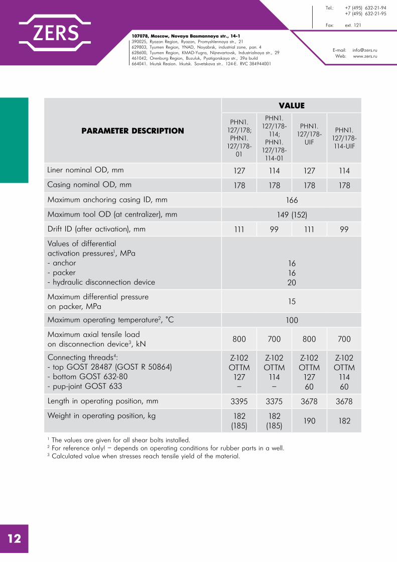
NON-CEMENTED LINER HANGER PHN1
The PHN1 liner hanger is used to RIH and hang non-cemented liners. It is manufactured in 2 modifications, differed by the type of internal space shut-off:
- by throttling valve, which gets closed by increased circulation rate;
- by pumping of cementing plug or activation ball, that land into a landing seat located at the bottom of hanger mandrel.
PHN1 is equipped with UIF (unit of isolation of filters), allowing to circulate through the liner shoe.
PHN1 hanger consists of 4 functionally independent parts:
- anchor to hang the liner assembly in the casing string;
- hydro-mechanical packer to isolate annular space;
- hydraulic release mechanism that allows to RIH liner assembly, circulate, activate anchor/packer by hydraulic pressure and, then, disconnect the drill string from PHN1 by applying hydraulic pressure.
- mechanical release to back up a hydraulic disconnection mechanism.
Design of PHN1 is practically identical to that of PHCZ1, except that at the end of tool mandrel, there installed a landing seat or a throttling shut-off valve, instead of hollow cement plug, and mandrel has circulation ports.
10

107078, �. l%“*"=, 3�. m%"= a=“�=……= , . 14, “2!. 1390025, p ƒ=…“*= %K�., . p ƒ=…�, o!%/���……= 3�., �. 21629803, Š��…“*= %K�., “m`n, . m% K!�“*, C!%ƒ%…=, C=…. 4628600, Š��…“*= %K�., ul`n-~ !=, . m,›…�"=!2%"“*, 3�. h…�3“2!,=��…= , �. 29461042, n!�…K3! “*= %K�., . a3ƒ3�3*, o 2, %!“*= 3�., �. 39=664041, h!*32“*= %K�., . h!*32“*, 3�. q%"�2“*= , �. 124-e, joo 384944001
E-mail: [email protected]: www.zers.ru
Š��.: +7 (495) 632-21-94 +7 (495) 632-21-95
t=*“: �%K. 121
PARAMETER DESCRIPTION
VALUE
PHN1. 102/146;PHN1.
102/146-01
PHN1. 114/168;PHN1.
114/168-01
PHN1.114/168-UIF
Liner nominal OD, mm 102 114
Casing nominal OD, mm 146 168
Maximum anchoring casing ID, mm 135 154
Maximum tool OD (at centralizer), mm 120 (122) 138 (141)
Drift ID (after activation), mm 89 99
Values of differential activation pressures1, MPa- anchor- packer- hydraulic disconnection device
16,516,520
161620
Maximum differential pressure on packer, MPa
15
Maximum operating temperature2, °C 100
Maximum axial tensile load on disconnection device3, kN
600 700
Connecting threads4:- top GOST 28487 (GOST R 50864)- bottom GOST 632-80- pup-joint GOST 633
Z-86ОТТМ 102
–
Z-102ОТТМ 114
–
Z-102ОТТМ 114
60
Length in operating position, mm 3340 3331 3563
Weight in operating position, kg 119 (125) 160 (163) 170
1 The values are given for all shear bolts installed.2 For reference only! – depends on operating conditions for rubber parts in a well.3 Calculated value when stresses reach tensile yield of the material.
11
E-mail: [email protected]: www.zers.ru
Tel.: +7 (495) 632-21-94 +7 (495) 632-21-95
Fax: ext. 121
107078, Moscow, Novaya Basmannaya str., 14-1390025, Ryazan Region, Ryazan, Promyshlennaya str., 21629803, Tyumen Region, YNAD, Noyabrsk, industrial zone, pan. 4628600, Tyumen Region, KMAD-Yugra, Nijnevartovsk, Industrialnaya str., 29461042, Orenburg Region, Buzuluk, Pyatigorskaya str., 39a build664041, Irkutsk Region, Irkutsk, Sovetskaya str., 124-e, RVC 384944001
PARAMETER DESCRIPTION
VALUE
PHN1. 127/178;PHN1.
127/178-01
PHN1. 127/178-
114;PHN1.
127/178- 114-01
PHN1.127/178-
UIF
PHN1. 127/178- 114-UIF
Liner nominal OD, mm 127 114 127 114
Casing nominal OD, mm 178 178 178 178
Maximum anchoring casing ID, mm 166
Maximum tool OD (at centralizer), mm 149 (152)
Drift ID (after activation), mm 111 99 111 99
Values of differential activation pressures1, MPa- anchor- packer- hydraulic disconnection device
161620
Maximum differential pressure on packer, MPa
15
Maximum operating temperature2, °C 100
Maximum axial tensile load on disconnection device3, kN
800 700 800 700
Connecting threads4:- top GOST 28487 (GOST R 50864)- bottom GOST 632-80- pup-joint GOST 633
Z-102ОТТМ 127–
Z-102ОТТМ 114–
Z-102ОТТМ 12760
Z-102ОТТМ 11460
Length in operating position, mm 3395 3375 3678 3678
Weight in operating position, kg 182 (185)
182 (185)
190 182
1 The values are given for all shear bolts installed.2 For reference only! – depends on operating conditions for rubber parts in a well.3 Calculated value when stresses reach tensile yield of the material.
12
107078, �. l%“*"=, 3�. m%"= a=“�=……= , . 14, “2!. 1390025, p ƒ=…“*= %K�., . p ƒ=…�, o!%/���……= 3�., �. 21629803, Š��…“*= %K�., “m`n, . m% K!�“*, C!%ƒ%…=, C=…. 4628600, Š��…“*= %K�., ul`n-~ !=, . m,›…�"=!2%"“*, 3�. h…�3“2!,=��…= , �. 29461042, n!�…K3! “*= %K�., . a3ƒ3�3*, o 2, %!“*= 3�., �. 39=664041, h!*32“*= %K�., . h!*32“*, 3�. q%"�2“*= , �. 124-e, joo 384944001
E-mail: [email protected]: www.zers.ru
Š��.: +7 (495) 632-21-94 +7 (495) 632-21-95
t=*“: �%K. 121
NON-CEMENTED LINER HANGER PHN2
The PHN2 liner hanger is used to RIH and hang non-cemented liners.
PHN2 liner hanger consists of 4 functionally independent parts:
- anchor to hang the liner assembly in the casing string;
- mechanical packer to isolate annular space;
- hydraulic release mechanism that allows to RIH liner assembly, circulate, activate anchor by hydraulic pressure, activate packer mechanically and, then, disconnect the drill string from PHN2 by applying hydraulic pressure.
- mechanical release to back up a hydraulic disconnection mechanism.
Design of PHN2 is practically identical to that of hydro-mechanical cemented liner hanger – PHGMC, except a landing seat installed at the bottom part of the mandrel.
Liner hangers PHN2.114/168, PHN2.127/178 and PHN2.127/178-114 are produced in UIF (unit of isolation of filters) configuration, which allows to perform circulation through the shoe.
13

E-mail: [email protected]: www.zers.ru
Tel.: +7 (495) 632-21-94 +7 (495) 632-21-95
Fax: ext. 121
107078, Moscow, Novaya Basmannaya str., 14-1390025, Ryazan Region, Ryazan, Promyshlennaya str., 21629803, Tyumen Region, YNAD, Noyabrsk, industrial zone, pan. 4628600, Tyumen Region, KMAD-Yugra, Nijnevartovsk, Industrialnaya str., 29461042, Orenburg Region, Buzuluk, Pyatigorskaya str., 39a build664041, Irkutsk Region, Irkutsk, Sovetskaya str., 124-e, RVC 384944001
PARAMETER DESCRIPTIONVALUE
PHN2. 102/140
PHN2. 102/146
PHN2. 114/168
Liner nominal OD, mm 102 102 114
Casing nominal OD, mm 140 146 168
Maximum anchoring casing ID, mm 127 132 132
Maximum tool OD (at centralizer), mm 115 (117) 120 (122) 138 (141)
Drift ID (after activation), mm 85 89 99
Values of differential activation pressures1, MPa- anchor- hydraulic disconnection device
1420
Load on packer for activation, kN 150
Maximum differential pressure between the zones isolated by a packer unit, MPa
30
Maximum operating temperature2, °C 100
Maximum axial tensile load on disconnection3, kN
600 600 700
Connecting threads4:- top GOST 28487 (GOST R 50864)- bottom GOST 632-80
Z-86ОТТМ 102
Z-102ОТТМ 102
Z-102ОТТМ 114
Length in operating position, mm 3612 3834 3810
Weight in operating position, kg 108 135 152
1 The values are given for all shear bolts installed.2 For reference only! – depends on operating conditions for rubber parts in a well.3 Calculated value when stresses reach tensile yield of the material.4 In PHN2.102/140 and PHN2.102/146 thread OTTM-102 is produced according to TU 14-161-163.
16

107078, �. l%“*"=, 3�. m%"= a=“�=……= , . 14, “2!. 1390025, p ƒ=…“*= %K�., . p ƒ=…�, o!%/���……= 3�., �. 21629803, Š��…“*= %K�., “m`n, . m% K!�“*, C!%ƒ%…=, C=…. 4628600, Š��…“*= %K�., ul`n-~ !=, . m,›…�"=!2%"“*, 3�. h…�3“2!,=��…= , �. 29461042, n!�…K3! “*= %K�., . a3ƒ3�3*, o 2, %!“*= 3�., �. 39=664041, h!*32“*= %K�., . h!*32“*, 3�. q%"�2“*= , �. 124-e, joo 384944001
E-mail: [email protected]: www.zers.ru
Š��.: +7 (495) 632-21-94 +7 (495) 632-21-95
t=*“: �%K. 121
PARAMETER DESCRIPTION
VALUE
PHN2.127/178
PHN2.127/178-
114
PHN2.168/245
PHN2.178/245
Liner nominal OD, mm 127 114 168 178
Casing nominal OD, mm 178 178 245 245
Maximum anchoring casing ID, mm 160 167 231 231
Maximum tool OD (at centralizer), mm 150 (152) 149 (152) 211 (213) 211 (213)
Drift ID (after activation), mm 111 99 150,5 157
Values of differential activation pressures1, MPa- anchor- hydraulic disconnection device
1420
Load on packer for activation, kN 150
Maximum differential pressure between the zones isolated by a packer unit, MPa
30
Maximum operating temperature2, °C 100
Maximum axial tensile load on disconnection3, kN
800 700 1000 1000
Connecting threads4:- top GOST 28487 (GOST R 50864)- bottom GOST 632-80
Z-102OTTM127
Z-102OTTM114
Z-133OTTM168
Z-133OTTM178
Length in operating position, mm 4138 4183 3769 4095
Weight in operating position, kg 209 240 385 420
1 The values are given for all shear bolts installed.2 For reference only! – depends on operating conditions for rubber parts in a well.3 Calculated value when stresses reach tensile yield of the material.4 In PHN2.102/140 and PHN2.102/146 thread OTTM-102 is produced according to TU 14-161-163.
17

E-mail: [email protected]: www.zers.ru
Tel.: +7 (495) 632-21-94 +7 (495) 632-21-95
Fax: ext. 121
107078, Moscow, Novaya Basmannaya str., 14-1390025, Ryazan Region, Ryazan, Promyshlennaya str., 21629803, Tyumen Region, YNAD, Noyabrsk, industrial zone, pan. 4628600, Tyumen Region, KMAD-Yugra, Nijnevartovsk, Industrialnaya str., 29461042, Orenburg Region, Buzuluk, Pyatigorskaya str., 39a build664041, Irkutsk Region, Irkutsk, Sovetskaya str., 124-e, RVC 384944001
ROTATING NON-CEMENTED LINER HANGER PHNV
The PHNV liner hanger is used to RIH and hang non-cemented liners, providing the capability to rotate an assembly while running.
PHNV liner hangers, can be produced in UIF (unit of isolation of filters) configuration, allowing to perform circulation through the liner shoe.
PHNV liner hanger consists of four functionally independent components:
- anchor to hang the liner assembly in the casing string;
- hydro-mechanical packer to isolate annular space;
- hydraulic release mechanism that allows to RIH liner assembly, circulate, activate anchor/packer by hydraulic pressure and, then, disconnect the drill string from PHN1 by applying hydraulic pressure.
- mechanical disconnection to back up a hydraulic release mechanism.
18

107078, �. l%“*"=, 3�. m%"= a=“�=……= , . 14, “2!. 1390025, p ƒ=…“*= %K�., . p ƒ=…�, o!%/���……= 3�., �. 21629803, Š��…“*= %K�., “m`n, . m% K!�“*, C!%ƒ%…=, C=…. 4628600, Š��…“*= %K�., ul`n-~ !=, . m,›…�"=!2%"“*, 3�. h…�3“2!,=��…= , �. 29461042, n!�…K3! “*= %K�., . a3ƒ3�3*, o 2, %!“*= 3�., �. 39=664041, h!*32“*= %K�., . h!*32“*, 3�. q%"�2“*= , �. 124-e, joo 384944001
E-mail: [email protected]: www.zers.ru
Š��.: +7 (495) 632-21-94 +7 (495) 632-21-95
t=*“: �%K. 121
PARAMETER DESCRIPTIONVALUE
PHNV1. 127/178-114-UIF OTTG
Liner nominal OD, mm 114
Casing nominal OD, mm 178
Maximum torque, kN*m 8
Maximum tool OD (at centralizer), mm 149 (152)
Drift ID (after activation), mm 99
Values of differential activation pressures1, MPa- anchor- packer- hydraulic disconnection device
161620
Maximum differential pressure on packer, MPa 15
Maximum operating temperature2, °C 100
Maximum axial tensile load on disconnection3, kN 700 (70)
Connecting threads4:- top GOST 28487 (GOST R 50864)- bottom GOST 632-80- pup-joint GOST 633
Z-102ОТТГ114
60
Length in operating position, mm 3950
Weight in operating position, kg 192
1 The values are given for all shear bolts installed.2 For reference only! – depends on operating conditions for rubber parts in a well.3 Calculated value when stresses reach tensile yield of the material.
19

E-mail: [email protected]: www.zers.ru
Tel.: +7 (495) 632-21-94 +7 (495) 632-21-95
Fax: ext. 121
107078, Moscow, Novaya Basmannaya str., 14-1390025, Ryazan Region, Ryazan, Promyshlennaya str., 21629803, Tyumen Region, YNAD, Noyabrsk, industrial zone, pan. 4628600, Tyumen Region, KMAD-Yugra, Nijnevartovsk, Industrialnaya str., 29461042, Orenburg Region, Buzuluk, Pyatigorskaya str., 39a build664041, Irkutsk Region, Irkutsk, Sovetskaya str., 124-e, RVC 384944001
NON-CEMENTED LINER HANGER WITH ORIENTED WHIPSTOCK PHN-KO
The PHN-KO liner hanger with oriented whipstock is used to RIH and hang non-cemented liners before kicking-off a second wellbore and running another non-cemented liner in it.
When using PHN-KO, the following operations are performed:
- the PHN-KO is RIH as a part of the liner assembly on drill string;
- azimuthal orientation of the whipstock in the well by the orienting tool – UOKS;
- hydraulic anchor actuation by increasing the pressure up to 13 MPa;
- fixing the rotating part of a whipstock in place and disconnecting the drill string using the hydraulic disconnection at 16 MPa.
The working mechanism of the hanger provides whipstock orientation in required direction. The pressure on the hanger parts is only transmitted if the whipstock is correctly set.
20

107078, �. l%“*"=, 3�. m%"= a=“�=……= , . 14, “2!. 1390025, p ƒ=…“*= %K�., . p ƒ=…�, o!%/���……= 3�., �. 21629803, Š��…“*= %K�., “m`n, . m% K!�“*, C!%ƒ%…=, C=…. 4628600, Š��…“*= %K�., ul`n-~ !=, . m,›…�"=!2%"“*, 3�. h…�3“2!,=��…= , �. 29461042, n!�…K3! “*= %K�., . a3ƒ3�3*, o 2, %!“*= 3�., �. 39=664041, h!*32“*= %K�., . h!*32“*, 3�. q%"�2“*= , �. 124-e, joo 384944001
E-mail: [email protected]: www.zers.ru
Š��.: +7 (495) 632-21-94 +7 (495) 632-21-95
t=*“: �%K. 121
PARAMETER DESCRIPTION
VALUE
PHN.KO1.121
PHN.KO1.143
PHN.KO1.153
Liner nominal OD, mm 102 114 114
Maximum OD, mm 114 136 136
Drift ID after activation, mm 52 60 60
Length in operating position, mm 5793 5610 5610
Weight in operating position, kg 309 423 423
Bit diameter for sidetracking, mm 123,8 142,9 152,4
Values of differential activation pressures1, MPa- anchor- disconnection device
1316
1316
1316
Whipstock kick-off angle 2°30’ 2°30’ 2°30’
Maximum operating temperature2, °C 100 100 100
Maximum tensile axial force3, kN 300 380 380
Connecting threads:- top GOST 28487 (GOST R 50864)- bottom GOST 632-80
Z-86ОТТМ- 102
Z-86ОТТМ-114
Z-86ОТТМ-114
1 The values are given for all shear bolts installed.2 For reference only! – depends on operating conditions for rubber parts in a well.3 Calculated value when stresses reach tensile yield of the material.
21
E-mail: [email protected]: www.zers.ru
Tel.: +7 (495) 632-21-94 +7 (495) 632-21-95
Fax: ext. 121
107078, Moscow, Novaya Basmannaya str., 14-1390025, Ryazan Region, Ryazan, Promyshlennaya str., 21629803, Tyumen Region, YNAD, Noyabrsk, industrial zone, pan. 4628600, Tyumen Region, KMAD-Yugra, Nijnevartovsk, Industrialnaya str., 29461042, Orenburg Region, Buzuluk, Pyatigorskaya str., 39a build664041, Irkutsk Region, Irkutsk, Sovetskaya str., 124-e, RVC 384944001
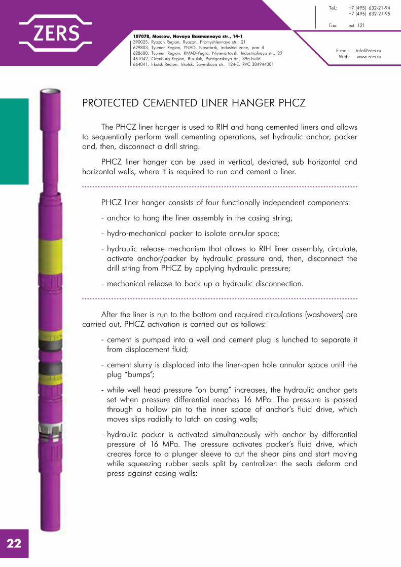
PROTECTED CEMENTED LINER HANGER PHCZ
The PHCZ liner hanger is used to RIH and hang cemented liners and allows to sequentially perform well cementing operations, set hydraulic anchor, packer and, then, disconnect a drill string.
PHCZ liner hanger can be used in vertical, deviated, sub horizontal and horizontal wells, where it is required to run and cement a liner.
PHCZ liner hanger consists of four functionally independent components:
- anchor to hang the liner assembly in the casing string;
- hydro-mechanical packer to isolate annular space;
- hydraulic release mechanism that allows to RIH liner assembly, circulate, activate anchor/packer by hydraulic pressure and, then, disconnect the drill string from PHCZ by applying hydraulic pressure;
- mechanical release to back up a hydraulic disconnection.
After the liner is run to the bottom and required circulations (washovers) are carried out, PHCZ activation is carried out as follows:
- cement is pumped into a well and cement plug is lunched to separate it from displacement fluid;
- cement slurry is displaced into the liner-open hole annular space until the plug “bumps”;
- while well head pressure “on bump” increases, the hydraulic anchor gets set when pressure differential reaches 16 MPa. The pressure is passed through a hollow pin to the inner space of anchor’s fluid drive, which moves slips radially to latch on casing walls;
- hydraulic packer is activated simultaneously with anchor by differential pressure of 16 MPa. The pressure activates packer’s fluid drive, which creates force to a plunger sleeve to cut the shear pins and start moving while squeezing rubber seals split by centralizer: the seals deform and press against casing walls;
22

107078, �. l%“*"=, 3�. m%"= a=“�=……= , . 14, “2!. 1390025, p ƒ=…“*= %K�., . p ƒ=…�, o!%/���……= 3�., �. 21629803, Š��…“*= %K�., “m`n, . m% K!�“*, C!%ƒ%…=, C=…. 4628600, Š��…“*= %K�., ul`n-~ !=, . m,›…�"=!2%"“*, 3�. h…�3“2!,=��…= , �. 29461042, n!�…K3! “*= %K�., . a3ƒ3�3*, o 2, %!“*= 3�., �. 39=664041, h!*32“*= %K�., . h!*32“*, 3�. q%"�2“*= , �. 124-e, joo 384944001
E-mail: [email protected]: www.zers.ru
Š��.: +7 (495) 632-21-94 +7 (495) 632-21-95
t=*“: �%K. 121
- when pressure differential reaches 20 MPa, the hydraulic disconnection device gets activated. The pressure on plunger creates force required to cut shear pins and move to release arresters, thus disconnecting the drill string from hanger;
- in case of problems with hydraulic release mechanism, the mechanical disconnection is activated by, first, adjusting weight indicator reading to the weight of the drill string in fluid and, second, rotating the drill string by 20 turns clockwise (to the right);
- circulation/washover is performed and drill pipe is POOH.
Depending on cementing job type required, the hanger/liner system is equipped with:
- for the “bottom up” liner cementing:
The first liner pipe is equipped with a plug catcher, check valve and casing shoe. PHCZ is connected to the last liner pipe.
- for liner top cementing
The first liner pipe is equipped with a shoe, the last liner pipe (in productive zone) is equipped with packer, such as PGMC, PGMC2 or PGMC4. PHCZ is connected to the last liner pipe.
23

E-mail: [email protected]: www.zers.ru
Tel.: +7 (495) 632-21-94 +7 (495) 632-21-95
Fax: ext. 121
107078, Moscow, Novaya Basmannaya str., 14-1390025, Ryazan Region, Ryazan, Promyshlennaya str., 21629803, Tyumen Region, YNAD, Noyabrsk, industrial zone, pan. 4628600, Tyumen Region, KMAD-Yugra, Nijnevartovsk, Industrialnaya str., 29461042, Orenburg Region, Buzuluk, Pyatigorskaya str., 39a build664041, Irkutsk Region, Irkutsk, Sovetskaya str., 124-e, RVC 384944001
PARAMETER DESCRIPTION
VALUE
PHCZ.89/140-76
PHCZ1.102/146
PHCZ1.114/168
Liner nominal OD, mm 89 102 114
Casing OD, recommended wall thickness, (ID) of casing to use PHCZ, mm
139,7*9,2
(121,3)
146,1*7,7
(130,7)
168,3*8,9
(150,5)
Maximum OD (at centralizer), mm 111 (114) 120 (122) 138 (141)
Drift ID after activation, mm 76 89 99
Maximum casing ID, where anchoring can be performed, mm
128 137 155
Values of differential activation pressures1, MPa- anchor- packer- hydraulic disconnection device
161620
Maximum pressure differential on packer, MPa
15
Maximum operating temperature2, °C 100
Maximum axial tensile load on hanger body parts3, kN
600 600 700
Connecting threads4:- top GOST 28487 (GOST R 50864)- bottom GOST 632-80
Z-8689
Z-86ОТТМ 102
Z-102ОТТМ 114
Length in operating position, mm 3361 3788 3757
Weight in operating position, kg 107 140 174,4
1 The values are given for all shear pins installed.2 For reference only! – depends on operating conditions for rubber parts in a well.3 Calculated value when stresses reach tensile yield of the material.4 For PHCZ.89/140-76 bottom thread is made accordingly to GOST 633. For PHCZ.102/140-80/117, PHCZ1.102/146, PHCZ1.114/168-102, PHCZ1.127/178-102 thread OTTM-102 is made accordingly to TR 14-161-163.
24

107078, �. l%“*"=, 3�. m%"= a=“�=……= , . 14, “2!. 1390025, p ƒ=…“*= %K�., . p ƒ=…�, o!%/���……= 3�., �. 21629803, Š��…“*= %K�., “m`n, . m% K!�“*, C!%ƒ%…=, C=…. 4628600, Š��…“*= %K�., ul`n-~ !=, . m,›…�"=!2%"“*, 3�. h…�3“2!,=��…= , �. 29461042, n!�…K3! “*= %K�., . a3ƒ3�3*, o 2, %!“*= 3�., �. 39=664041, h!*32“*= %K�., . h!*32“*, 3�. q%"�2“*= , �. 124-e, joo 384944001
E-mail: [email protected]: www.zers.ru
Š��.: +7 (495) 632-21-94 +7 (495) 632-21-95
t=*“: �%K. 121
PARAMETER DESCRIPTION
VALUE
PHCZ1.114/168-
102
PHCZ1.127/178
PHCZ1.127/178-
114
PHCZ1.127/178-
102
Liner nominal OD, mm 102 127 114 102
Casing OD, recommended wall thickness, (ID) of casing to use PHCZ, mm
168,3*8,9
(150,5)
177,8*10,4(157)
Maximum OD (at centralizer), mm 138 (141) 149 (152)
Drift ID after activation, mm 89 111 99 89
Maximum casing ID, where anchoring can be performed, mm
155 167
Values of differential activation pressures1, MPa- anchor- packer- hydraulic disconnection device
161620
Maximum differential pressure on packer, MPa
15
Maximum operating temperature2, °C 100
Maximum axial tensile load on hanger body parts3, kN
600 800 700 600
Connecting threads4:- top GOST 28487 (GOST R 50864)- bottom GOST 632-80
Z-102ОТТМ 102
Z-102ОТТМ 127
Z-102ОТТМ 114
Z-102ОТТМ 102
Length in operating position, mm 3757 3678 3775 3765
Weight in operating position, kg 174,4 187 187 180,4
1 The values are given for all shear pins installed.2 For reference only! – depends on operating conditions for rubber parts in a well.3 Calculated value when stresses reach tensile yield of the material.4 For PHCZ.89/140-76 bottom thread is in line with GOST 633. For PHCZ.102/140-80/117, PHCZ1.102/146, PHCZ1.114/168-102, PHCZ1.127/178-102 thread OTTM-102 is in line with to TR 14-161-163.
25

E-mail: [email protected]: www.zers.ru
Tel.: +7 (495) 632-21-94 +7 (495) 632-21-95
Fax: ext. 121
107078, Moscow, Novaya Basmannaya str., 14-1390025, Ryazan Region, Ryazan, Promyshlennaya str., 21629803, Tyumen Region, YNAD, Noyabrsk, industrial zone, pan. 4628600, Tyumen Region, KMAD-Yugra, Nijnevartovsk, Industrialnaya str., 29461042, Orenburg Region, Buzuluk, Pyatigorskaya str., 39a build664041, Irkutsk Region, Irkutsk, Sovetskaya str., 124-e, RVC 384944001
ROTATING PROTECTED CEMENTED LINER HANGER PHCZV
PHCZV liner hanger is used to RIH and hang cemented liners, providing the capabilities to rotate an assembly while running, hang cemented liners and allows to sequentially perform well cementing operations, set hydraulic anchor, packer and, then, disconnect a drill string.
PHCZV liner hanger consists of four functionally independent components:
- anchor to hang the liner assembly in the casing string;
- hydro-mechanical packer to isolate annular space;
- hydraulic release mechanism that allows to RIH liner assembly, circulate, activate anchor/packer by hydraulic pressure and, then, disconnect the drill string from PHCZV by applying hydraulic pressure.
- mechanical disconnection that allows clockwise (to the right) assembly rotation while RIH and, at the same time, serves a backup to hydraulic disconnection. To disconnect the drill string, first, the half a turn counterclockwise turn is performed (to the left) to activate and, second, not less than 10 clockwise (to the right) turns to disconnect.
After the liner is run to the bottom and required circulations (washovers) are carried out, PHCZV activation is carried out as follows:
- cement is pumped into a well and cement plug is lunched to separate it from displacement fluid;
- cement slurry is displaced into the liner-open hole annular space until the plug “bumps”;
- while well head pressure “on bump” increases, the hydraulic anchor gets set when pressure differential reaches 16 MPa;
- hydraulic packer is activated simultaneously with anchor by differential pressure of 16 MPa;
- when pressure differential reaches 20 MPa, the hydraulic disconnection gets activated;
26

107078, �. l%“*"=, 3�. m%"= a=“�=……= , . 14, “2!. 1390025, p ƒ=…“*= %K�., . p ƒ=…�, o!%/���……= 3�., �. 21629803, Š��…“*= %K�., “m`n, . m% K!�“*, C!%ƒ%…=, C=…. 4628600, Š��…“*= %K�., ul`n-~ !=, . m,›…�"=!2%"“*, 3�. h…�3“2!,=��…= , �. 29461042, n!�…K3! “*= %K�., . a3ƒ3�3*, o 2, %!“*= 3�., �. 39=664041, h!*32“*= %K�., . h!*32“*, 3�. q%"�2“*= , �. 124-e, joo 384944001
E-mail: [email protected]: www.zers.ru
Š��.: +7 (495) 632-21-94 +7 (495) 632-21-95
t=*“: �%K. 121
- mechanical disconnection is activated by, first rotating the drill string by 1/2 turn counterclockwise (to the left) and, second, disconnected by not less than 10 turns clockwise (to the right);
- circulation/washover is performed and drill pipe is POOH.
- washover and pulling out of the transport string.
While well casing a liner includes the following technical units:
- for liner continuous cementing
liner casing starter is equipped with a shoe, than check-valve and stopping branch pipe. Hanger PHCZV is mounted on the last pipe of the liner which is connected with the transport string;
- for liner collar cementing
casing starter of liner filtering part is equipped with a shoe, above the filtering part a packer for collar cementing is mounted, PGMC, PGMC2 or PGMC4. Hanger PHCZV is mounted on the last part of the liner which is connected with the transport string.
27

E-mail: [email protected]: www.zers.ru
Tel.: +7 (495) 632-21-94 +7 (495) 632-21-95
Fax: ext. 121
107078, Moscow, Novaya Basmannaya str., 14-1390025, Ryazan Region, Ryazan, Promyshlennaya str., 21629803, Tyumen Region, YNAD, Noyabrsk, industrial zone, pan. 4628600, Tyumen Region, KMAD-Yugra, Nijnevartovsk, Industrialnaya str., 29461042, Orenburg Region, Buzuluk, Pyatigorskaya str., 39a build664041, Irkutsk Region, Irkutsk, Sovetskaya str., 124-e, RVC 384944001
PARAMETER DESCRIPTION
VALUE
PHCZV.102/146
PHCZV.114/168-102
PHCZV.114/168
Liner nominal diameter RIH with the device, mm
102 102 114
Diameter, recommended wall thickness (ID) of casing string which the device is run into and installed, mm
146,*7,7
(130,7)
168,3*8,9
(150,5)
Maximum OD of the device body (at centralizer), mm
120 (122) 138 (141) 138 (141)
Min. drift diameter after actuation, mm 89 89 99
Maximum torque, kN*m 6 7 7
Maximum ID of a casing string in which anchoring is performed, mm
137 155 155
Values of controlling internal overpressure for actuation of units1, MPa- anchor unit- packer unit- hydraulic disconnection device
161620
Maximum differential pressure between the zones isolated by a packer, MPa
15
Maximum operating temperature2, °C 100
Maximum tensile force on the body parts3, kN
600 600 700
Connecting threads:- top GOST 28487 (GOST R 50864)- bottom GOST 632-80
Z-86TMK PF 102
Z 3-102TMK PF 102
Z-102OTTG 114
Length in operating position, mm 3894 4023 4023
Weight in operating position, kg 157 182 184
1 Controlling overpressure values are given when all the shear bolts on the unit are used.2 Reference only, depends on operating conditions of general mechanical rubber goods in a well.3 Calculated value when stresses reach yield point of the material.
28

107078, �. l%“*"=, 3�. m%"= a=“�=……= , . 14, “2!. 1390025, p ƒ=…“*= %K�., . p ƒ=…�, o!%/���……= 3�., �. 21629803, Š��…“*= %K�., “m`n, . m% K!�“*, C!%ƒ%…=, C=…. 4628600, Š��…“*= %K�., ul`n-~ !=, . m,›…�"=!2%"“*, 3�. h…�3“2!,=��…= , �. 29461042, n!�…K3! “*= %K�., . a3ƒ3�3*, o 2, %!“*= 3�., �. 39=664041, h!*32“*= %K�., . h!*32“*, 3�. q%"�2“*= , �. 124-e, joo 384944001
E-mail: [email protected]: www.zers.ru
Š��.: +7 (495) 632-21-94 +7 (495) 632-21-95
t=*“: �%K. 121
PARAMETER DESCRIPTION
VALUE
PHCZV.127/178
PHCZV.127/178-114
Liner nominal diameter RIH with the device, mm
127 114
Diameter, recommended wall thickness (ID) of casing string which the device is run into and installed, mm
177,8*10,4 (157)
Maximum OD of the device body (at centralizer), mm
149 (152) 149 (152)
Min. drift diameter after actuation, mm 111 99
Maximum torque, kN*m 8 8
Maximum ID of a casing string in which anchoring is performed, mm
167 167
Values of controlling internal overpressure for actuation of units1, MPa- anchor unit- packer unit- hydraulic disconnection
161620
Maximum differential pressure between the zones isolated by a packer, MPa
15
Maximum operating temperature2, °C 100
Maximum tensile force on the body parts3, kN
800 700
Connecting threads:- top GOST 28487 (GOST R 50864)- bottom GOST 632-80
Z-102OTTG-127
Z-102OTTG-114
Length in operating position, mm 3945 3945
Weight in operating position, kg 195 2011 Controlling overpressure values are given when all the shear bolts on the unit are used.2 Reference only, depends on operating conditions of general mechanical rubber goods in a well.3 Calculated value when stresses reach yield point of the material.
29

E-mail: [email protected]: www.zers.ru
Tel.: +7 (495) 632-21-94 +7 (495) 632-21-95
Fax: ext. 121
107078, Moscow, Novaya Basmannaya str., 14-1390025, Ryazan Region, Ryazan, Promyshlennaya str., 21629803, Tyumen Region, YNAD, Noyabrsk, industrial zone, pan. 4628600, Tyumen Region, KMAD-Yugra, Nijnevartovsk, Industrialnaya str., 29461042, Orenburg Region, Buzuluk, Pyatigorskaya str., 39a build664041, Irkutsk Region, Irkutsk, Sovetskaya str., 124-e, RVC 384944001
HYDRO-MECHANICAL CEMENTED LINER HANGER PHGMC
Hydro-Mechanical Cemented Liner Hanger PHGMC is designed for RIH, hanging and sealing in of cementing liner, performing of technological operations connected with cementing and sequential actuation of an anchor unit and a packer unit and further automatic disconnection of transport string from the liner and transport string pulling out.
PHGMC hanger is a complex of four stand-alone and independent units:
- hydraulic anchor;
- hydraulic disconnection device;
- mechanical packer;
- mechanical release unit doubling the hydraulic one.
The hanger is provided with a number of interlocks: hydraulic breaking is protected against early actuation before the hollow suspended plug is cut, the packer may be actuated only after disconnection.
The hanger consists of two parts: adjustment tool and the hanger itself, the latter includes packer unit, anchor unit and lead-in funnel.
When using hangers like PHGMC the following technological operations are performed:
- RIH of the device as a part of a transport string liner;
- performing of washovers with limited pressure (no more than 75% of anchoring pressure);
- washover at the bottomhole without pressure limits (anchor actuation changes annular space insignificantly);
- performing of liner cementing with running of the cementing plug after the injection of the cement slurry for its separation from the displacement fluid;
- displacing the cement slurry to the outer annular space of the liner with limited displacement pressure after the suspended plug is cut off (no more than 75% of disconnection pressure) and receiving of “ bump” signal;
30
107078, �. l%“*"=, 3�. m%"= a=“�=……= , . 14, “2!. 1390025, p ƒ=…“*= %K�., . p ƒ=…�, o!%/���……= 3�., �. 21629803, Š��…“*= %K�., “m`n, . m% K!�“*, C!%ƒ%…=, C=…. 4628600, Š��…“*= %K�., ul`n-~ !=, . m,›…�"=!2%"“*, 3�. h…�3“2!,=��…= , �. 29461042, n!�…K3! “*= %K�., . a3ƒ3�3*, o 2, %!“*= 3�., �. 39=664041, h!*32“*= %K�., . h!*32“*, 3�. q%"�2“*= , �. 124-e, joo 384944001
E-mail: [email protected]: www.zers.ru
Š��.: +7 (495) 632-21-94 +7 (495) 632-21-95
t=*“: �%K. 121
- anchor unit actuation with internal overpressure build-up to 14 MPa;
- hydraulic breaking unit actuation with pressure build-up to 20 MPa;
- mechanical breaking unit actuation with transport string rotation to the right;
- packer unit actuation by partial uploading of the transport string weight onto the “head” part of the liner;
- washover and pulling out of the transport string.
31

E-mail: [email protected]: www.zers.ru
Tel.: +7 (495) 632-21-94 +7 (495) 632-21-95
Fax: ext. 121
107078, Moscow, Novaya Basmannaya str., 14-1390025, Ryazan Region, Ryazan, Promyshlennaya str., 21629803, Tyumen Region, YNAD, Noyabrsk, industrial zone, pan. 4628600, Tyumen Region, KMAD-Yugra, Nijnevartovsk, Industrialnaya str., 29461042, Orenburg Region, Buzuluk, Pyatigorskaya str., 39a build664041, Irkutsk Region, Irkutsk, Sovetskaya str., 124-e, RVC 384944001
PARAMETER DESCRIPTION
VALUE
PHGMC.102/140-85/117
PHGMC.102/140-89/119
PHGMC.102/146
PHGMC.114/
168-102
Liner nominal diameter RIH with the device, mm
102 102 102 102
Nominal diameter of casing string which the device is run into and installed, mm
140 140 146 168
Maximum OD of the device body (at centralizer), mm
115 (117) 117 (119) 120 (122) 138 (141)
Min. drift diameter after actuation, mm 85 89 89 89
Maximum ID of a casing string in which anchoring is performed, mm
127 129 132 158
Values of controlling internal overpressure for actuation of units1, MPa- anchoring unit- breaker unit
18,523,5
1420
Maximum differential pressure between the zones isolated by the hydro-mechanical packer, MPa
30
Maximum operating temperature2, °C 100
Maximum tensile axial force on the body of a disconnection device3, kN
600 600 600 600
Connecting threads:- top GOST 28487 (GOST R 50864)- bottom TR 14-161-163
Z-86ОТТМ-102
Z-86OTTM-102
Z-102ОТТМ-102
Z-133ОТТМ-102
Length in operating position, mm 3612 3687 3754 3769
Weight in operating position, kg 107,5 110 152 1521 Controlling overpressure values are given when all the shear bolts on the unit are used.2 Reference only, depends on operating conditions of general mechanical rubber goods in a well.3 Calculated value when stresses reach yield point of the material.
32

107078, �. l%“*"=, 3�. m%"= a=“�=……= , . 14, “2!. 1390025, p ƒ=…“*= %K�., . p ƒ=…�, o!%/���……= 3�., �. 21629803, Š��…“*= %K�., “m`n, . m% K!�“*, C!%ƒ%…=, C=…. 4628600, Š��…“*= %K�., ul`n-~ !=, . m,›…�"=!2%"“*, 3�. h…�3“2!,=��…= , �. 29461042, n!�…K3! “*= %K�., . a3ƒ3�3*, o 2, %!“*= 3�., �. 39=664041, h!*32“*= %K�., . h!*32“*, 3�. q%"�2“*= , �. 124-e, joo 384944001
E-mail: [email protected]: www.zers.ru
Š��.: +7 (495) 632-21-94 +7 (495) 632-21-95
t=*“: �%K. 121
PARAMETER DESCRIPTION
VALUE
PHGMC.114/168
PHGMC. 127/178-
114
PHGMC. 178/245-
114
PHGMC. 127/178
Liner nominal diameter RIH with the device, mm
114 114 114 127
Nominal diameter of casing string which the device is run into and installed, mm
168 178 245 178
Maximum OD of the device body (at centralizer), mm
138 (141) 150 (152) 211 (213) 150 (152)
Min. drift diameter after actuation, mm 99 99 99 111
Maximum ID of a casing string in which anchoring is performed, mm
158 160 231 160
Values of controlling internal overpressure for actuation of units1, MPa- anchoring unit- hydraulic disconnection device
1420
Maximum differential pressure between the zones isolated by the hydro-mechanical packer, MPa
30
Maximum operating temperature2, °C 100
Maximum tensile axial force on the body of a disconnection device3, kN
700 700 700 800
Connecting threads:- top GOST 28487 (GOST R 50864)- bottom GOST 632-80
Z-102ОТТМ-114
Z-102ОТТМ-114
Z-102ОТТМ-114
Z-102ОТТМ-127
Length in operating position, mm 3769 3875 4265 3855
Weight in operating position, kg 152 213 400 1961 Controlling overpressure values are given when all the shear bolts on the unit are used.2 Reference only, depends on operating conditions of general mechanical rubber goods in a well.3 Calculated value when stresses reach yield point of the material.
33

E-mail: [email protected]: www.zers.ru
Tel.: +7 (495) 632-21-94 +7 (495) 632-21-95
Fax: ext. 121
107078, Moscow, Novaya Basmannaya str., 14-1390025, Ryazan Region, Ryazan, Promyshlennaya str., 21629803, Tyumen Region, YNAD, Noyabrsk, industrial zone, pan. 4628600, Tyumen Region, KMAD-Yugra, Nijnevartovsk, Industrialnaya str., 29461042, Orenburg Region, Buzuluk, Pyatigorskaya str., 39a build664041, Irkutsk Region, Irkutsk, Sovetskaya str., 124-e, RVC 384944001
PARAMETER DESCRIPTION
VALUE
PHGMC. 146/219
PHGMC. 178/245-
146
PHGMC. 168/245
PHGMC. 178/245
Liner nominal diameter RIH with the device, mm
146 146 168 178
Nominal diameter of casing string which the device is run into and installed, mm
219 245
Maximum OD of the device body (at centralizer), mm
182 (184) 211 (213)
Min. drift diameter after actuation, mm129 129 150,5 157
Maximum ID of a casing string in which anchoring is performed, mm 196 231
Values of controlling internal overpressure for actuation of units1, MPa- anchoring unit- hydraulic disconnection devicet
1620
1420
Maximum differential pressure between the zones isolated by the hydro-mechanical packer, MPa
30 15 15 15
Maximum temperatureoperating temperature2, °C
100
Maximum tensile axial force on the body of a disconnection device3, kN
1000
Connecting threads:- top GOST 28487 (GOST R 50864)- bottom GOST 632-80
Z-133ОТТМ-146
Z-133ОТТМ-146
Z-133ОТТМ-
168
Z-133ОТТМ-
178
Length in operating position, mm 4010 4275 3769 4095
Weight in operating position, kg 319 400 385 3801 Controlling overpressure values are given when all the shear bolts on the unit are used.2 Reference only, depends on operating conditions of general mechanical rubber goods in a well.3 Calculated value when stresses reach yield point of the material.
34

107078, �. l%“*"=, 3�. m%"= a=“�=……= , . 14, “2!. 1390025, p ƒ=…“*= %K�., . p ƒ=…�, o!%/���……= 3�., �. 21629803, Š��…“*= %K�., “m`n, . m% K!�“*, C!%ƒ%…=, C=…. 4628600, Š��…“*= %K�., ul`n-~ !=, . m,›…�"=!2%"“*, 3�. h…�3“2!,=��…= , �. 29461042, n!�…K3! “*= %K�., . a3ƒ3�3*, o 2, %!“*= 3�., �. 39=664041, h!*32“*= %K�., . h!*32“*, 3�. q%"�2“*= , �. 124-e, joo 384944001
E-mail: [email protected]: www.zers.ru
Š��.: +7 (495) 632-21-94 +7 (495) 632-21-95
t=*“: �%K. 121
PROTECTED HYDRO-MECHANICAL CEMENTED LINER HANGER PHGMCZ
Hydro-Mechanical Cemented Liner Hanger PHGMC with increased carrying capacity is designed for RIH, hanging and sealing in of a liner in a cemented well; performing of technological operations connected with cementing and sequential actuation of an anchor unit and a packer unit and further automatic disconnection of transport string from the liner and transport string pulling out.
PHGMCZ hanger is a complex of four stand-alone and independent units:
- hydraulic anchor;
- hydraulic release mechanism;
- mechanical packer;
- mechanical disconnection to back up hydraulic release mechanism.
The hanger is provided with a number of interlocks: hydraulic disconnection and hydraulic anchor are protected against early actuation before the hollow suspended plug is cut, the packer unit may be actuated only after disconnection.
The hanger consists of 2 parts: adjustment tool and the hanger itself, the latter includes packer unit, anchor unit and lead-in funnel.
When using hangers like PHGMCZ the following technological operations are performed:
- RIH of the device as a part of a transport string liner;
- washovers without pressure limitation;
- performing of liner cementing with running of the cementing plug after the injection of the cement slurry for its separation from the displacement fluid;
- displacing of the cement slurry to the outer annular space of the liner with limited displacement pressure after the suspended plug is cut off (no more than 75% of disconnection pressure) and receiving of “bump” signal;
- anchor unit actuation with internal overpressure build-up to 14 MPa;
- hydraulic breaking unit actuation with pressure build-up to 20 MPa;
35

E-mail: [email protected]: www.zers.ru
Tel.: +7 (495) 632-21-94 +7 (495) 632-21-95
Fax: ext. 121
107078, Moscow, Novaya Basmannaya str., 14-1390025, Ryazan Region, Ryazan, Promyshlennaya str., 21629803, Tyumen Region, YNAD, Noyabrsk, industrial zone, pan. 4628600, Tyumen Region, KMAD-Yugra, Nijnevartovsk, Industrialnaya str., 29461042, Orenburg Region, Buzuluk, Pyatigorskaya str., 39a build664041, Irkutsk Region, Irkutsk, Sovetskaya str., 124-e, RVC 384944001
36
- mechanical breaking unit actuation with transport string rotation to the right;
- packer unit actuation by partial uploading of the transport string weight onto the “head” part of the liner;
- washover and pulling out of the transport string.

107078, �. l%“*"=, 3�. m%"= a=“�=……= , . 14, “2!. 1390025, p ƒ=…“*= %K�., . p ƒ=…�, o!%/���……= 3�., �. 21629803, Š��…“*= %K�., “m`n, . m% K!�“*, C!%ƒ%…=, C=…. 4628600, Š��…“*= %K�., ul`n-~ !=, . m,›…�"=!2%"“*, 3�. h…�3“2!,=��…= , �. 29461042, n!�…K3! “*= %K�., . a3ƒ3�3*, o 2, %!“*= 3�., �. 39=664041, h!*32“*= %K�., . h!*32“*, 3�. q%"�2“*= , �. 124-e, joo 384944001
E-mail: [email protected]: www.zers.ru
Š��.: +7 (495) 632-21-94 +7 (495) 632-21-95
t=*“: �%K. 121
PARAMETER DESCRIPTION
VALUE
PHGMCZ.114/168
PHGMCZ. 127/178
PHGMCZ. 127/178-114
Liner nominal diameter RIH with the device, mm
114 127 114
Nominal diameter of casing string which the device is run into and installed, mm
168 178 178
Maximum OD of the device body (at centralizer), mm
143 150 (152) 150 (152)
Min. drift diameter after actuation, mm 99 111 99
Maximum ID of a casing string in which anchoring is performed, mm
157 167 167
Values of controlling internal overpressure for actuation of units1, MPa- anchoring unit- hydraulic disconnection device
1420
Maximum differential pressure between the zones isolated by the hydro-mechanical packer, MPa
30
Maximum operating temperature2, °C 100
Maximum tensile axial force on the body of a disconnection device3, kN
1000 (100)
Connecting threads:- top GOST 28487 (GOST R 50864)- bottom TR 14-161-163
Z-102ОТТМ-114
Z-102ОТТМ-127
Z-102ОТТМ-114
Length in operating position, mm 4059 4045 4065
Weight in operating position, kg 165 196 2131 Controlling overpressure values are given when all the shear bolts on the unit are used.2 Reference only, depends on operating conditions of general mechanical rubber goods in a well.3 Calculated value when stresses reach yield point of the material.
37

E-mail: [email protected]: www.zers.ru
Tel.: +7 (495) 632-21-94 +7 (495) 632-21-95
Fax: ext. 121
107078, Moscow, Novaya Basmannaya str., 14-1390025, Ryazan Region, Ryazan, Promyshlennaya str., 21629803, Tyumen Region, YNAD, Noyabrsk, industrial zone, pan. 4628600, Tyumen Region, KMAD-Yugra, Nijnevartovsk, Industrialnaya str., 29461042, Orenburg Region, Buzuluk, Pyatigorskaya str., 39a build664041, Irkutsk Region, Irkutsk, Sovetskaya str., 124-e, RVC 384944001
LINER HANGER WITH DISCONNECTION BEFORE CEMENTING PHRC
Liner Hanger with disconnection before cementing PHRC is designed for RIH, hanging and liner sealing in the well.
The device is a complex of three stand-alone and independent units on the same body:
- anchor unit which ensures liner hanging in service string;
- mechanical packer unit which ensures sealing in of inner annular space;
- mechanical breaking unit which ensures RIH of units together with the liner, performance of technological operations such as washover, actuation of anchor unit, mechanical disconnection of the transport string from the device, liner cementing followed by packer unit actuation.
The hanger consists of two parts: adjustment tool and the hanger itself, the latter includes packer unit, anchor unit and lead-in funnel.
When using hangers like PHRC the following technological operations are performed:
- RHI of the device as a part of a transport string liner;
- washovers with limited pressure (no more than 75% of anchoring pressure);
- washover of the bottomhole without pressure limits (anchor actuation changes annular space insignificantly);
- ball-drop and its driving until its setting in the PGMC packer seat or in a special seat set above the check valve;
- PGMC actuation (for collar cementing);
- anchor unit actuation with internal overpressure build-up to 13 MPa;
- the pressure build-up to 16 MPa opens PGMC packer cementing ports (for collar cementing) or the pressure build-up to 20 MPa leads to shearing of a special seat with a ball to restore circulation;
38

107078, �. l%“*"=, 3�. m%"= a=“�=……= , . 14, “2!. 1390025, p ƒ=…“*= %K�., . p ƒ=…�, o!%/���……= 3�., �. 21629803, Š��…“*= %K�., “m`n, . m% K!�“*, C!%ƒ%…=, C=…. 4628600, Š��…“*= %K�., ul`n-~ !=, . m,›…�"=!2%"“*, 3�. h…�3“2!,=��…= , �. 29461042, n!�…K3! “*= %K�., . a3ƒ3�3*, o 2, %!“*= 3�., �. 39=664041, h!*32“*= %K�., . h!*32“*, 3�. q%"�2“*= , �. 124-e, joo 384944001
E-mail: [email protected]: www.zers.ru
Š��.: +7 (495) 632-21-94 +7 (495) 632-21-95
t=*“: �%K. 121
- disconnection of an adjustment tool from the hanger through relief of the transport string and its rotation to the right at least 10 times;
- performing of liner cementing with running of the cementing plug after the injection of the cement slurry for its separation from the displacement fluid;
- displacing the cement slurry to the outer annular space of the liner and receiving of “stop” signal;
- packer unit actuation by partial uploading of the transport string weight onto the “head” part of the liner;
- washover and pulling out of the transport string.
39

E-mail: [email protected]: www.zers.ru
Tel.: +7 (495) 632-21-94 +7 (495) 632-21-95
Fax: ext. 121
107078, Moscow, Novaya Basmannaya str., 14-1390025, Ryazan Region, Ryazan, Promyshlennaya str., 21629803, Tyumen Region, YNAD, Noyabrsk, industrial zone, pan. 4628600, Tyumen Region, KMAD-Yugra, Nijnevartovsk, Industrialnaya str., 29461042, Orenburg Region, Buzuluk, Pyatigorskaya str., 39a build664041, Irkutsk Region, Irkutsk, Sovetskaya str., 124-e, RVC 384944001
40
PARAMETER DESCRIPTION
VALUE
PHRC. 102/140-89/119
PHRC. 102/146
PHRC. 114/168 -102
Liner nominal diameter RIH with the device, mm
102 102 102
Casing string nominal diameter which the device is RIH and installed, mm
140 146 168
Maximum OD of the device body (at centralizer), mm
117 (119) 120 (122) 138 (141)
Min. drift diameter after actuation, mm 89 89 89
Maximum ID of a casing string in which anchoring is performed, mm
127 132 158
Internal overpressure for anchoring unit actuation, MPa
13,0±5%
Maximum swinging moment at the mechanical disconnection, kg*m
30–40
Maximum tensile force1, kN 600
Maximum pressure differential between the zones isolated by a packer unit, P, MPa
30
Maximum internal overpressure, MPa 25
Maximum operating temperature2, °C 100
Connecting threads:- top according to GOST 28487-90- bottom according to TR 14-161-163-96
Z-86ОТТМ-102
Z-86ОТТМ-102
Z-102ОТТМ-102
Length in operating position, mm 4478 4490 4686
Weight in operating position, kg 130,5 144,5 2171 Calculated value when stresses reach yield point of the material.2 Reference only, depends on operating conditions of general mechanical rubber goods in a well.

107078, �. l%“*"=, 3�. m%"= a=“�=……= , . 14, “2!. 1390025, p ƒ=…“*= %K�., . p ƒ=…�, o!%/���……= 3�., �. 21629803, Š��…“*= %K�., “m`n, . m% K!�“*, C!%ƒ%…=, C=…. 4628600, Š��…“*= %K�., ul`n-~ !=, . m,›…�"=!2%"“*, 3�. h…�3“2!,=��…= , �. 29461042, n!�…K3! “*= %K�., . a3ƒ3�3*, o 2, %!“*= 3�., �. 39=664041, h!*32“*= %K�., . h!*32“*, 3�. q%"�2“*= , �. 124-e, joo 384944001
E-mail: [email protected]: www.zers.ru
Š��.: +7 (495) 632-21-94 +7 (495) 632-21-95
t=*“: �%K. 121
41
PARAMETER DESCRIPTION
VALUE
PHRC. 114/168
PHRC. 127/178
PHRC. 127/178 -114
Liner nominal diameter RIH with the device, mm
114 127 114
Casing string nominal diameter which the device is RIH and installed, mm
168 178 178
Maximum OD of the device body (at centralizer), mm
138 (141) 149 (152) 149 (152)
Min. drift diameter after actuation, mm 99 111 99
Maximum ID of a casing string in which anchoring is performed, mm
158 164 164
Internal overpressure for anchoring unit actuation, MPa
13,0±5%
Maximum swinging moment at the mechanical disconnection, kg*m
30–40
Maximum tensile force1, kN 700 800 700
Maximum pressure differential between the zones isolated by a packer unit, P, MPa
30
Maximum internal overpressure, MPa 25
Maximum operating temperature2, °C 100
Connecting threads:- top according to GOST 28487-90- bottom according to TR 14-161-163-96
Z-102ОТТМ-114
Z-102ОТТМ-127
Z-102ОТТМ-114
Length in operating position, mm 4670 4689 4709
Weight in operating position, kg 208,8 219,6 226,71 Calculated value when stresses reach yield point of the material.2 Reference only, depends on operating conditions of general mechanical rubber goods in a well.

E-mail: [email protected]: www.zers.ru
Tel.: +7 (495) 632-21-94 +7 (495) 632-21-95
Fax: ext. 121
107078, Moscow, Novaya Basmannaya str., 14-1390025, Ryazan Region, Ryazan, Promyshlennaya str., 21629803, Tyumen Region, YNAD, Noyabrsk, industrial zone, pan. 4628600, Tyumen Region, KMAD-Yugra, Nijnevartovsk, Industrialnaya str., 29461042, Orenburg Region, Buzuluk, Pyatigorskaya str., 39a build664041, Irkutsk Region, Irkutsk, Sovetskaya str., 124-e, RVC 384944001
CEMENTED LINER HANGER FOR FLUSH-JOINT PIPES PHCBT
Cemented Liner Hanger for flush-joint pipes PHCBT is applied for RIH and continuous cementing of a liner consisting of flush-joint pipes.
The PHCBT liner hanger consists of the top sub and the body joined with the bottom sub by special left-hand thread. There is a special groove in the body that holds the collet supported by the piston which is held by shear bolts. There is a suspended plug positioned within the inner channel of the device mounted with two hollow shear plugs.
The device operates as follows. While liner cementing top wiper plug is touching down the suspended plug seat and the shearing of two hollow plugs is performed due to the pressure build-up, the access of fluid to the plunger space is opened. The pressure build-up is performed after receiving the “stop” signal, shear bolts are ruined and plunger moves releasing a collet. Under tension the blades of the collet clench and therefore the liner is disconnected from the transport string.
The liner hanger is equipped with the mechanical breaking unit doubling the hydraulic one. It is actuated by transport string rotation to the right.
The device application area is vertical, tilting (flat) wellbores and bores with horizontal ends whereinto casing strings with diameter 102, 114, 120 and 140 mm are run in consisting of flush-joint pipes.
42

107078, �. l%“*"=, 3�. m%"= a=“�=……= , . 14, “2!. 1390025, p ƒ=…“*= %K�., . p ƒ=…�, o!%/���……= 3�., �. 21629803, Š��…“*= %K�., “m`n, . m% K!�“*, C!%ƒ%…=, C=…. 4628600, Š��…“*= %K�., ul`n-~ !=, . m,›…�"=!2%"“*, 3�. h…�3“2!,=��…= , �. 29461042, n!�…K3! “*= %K�., . a3ƒ3�3*, o 2, %!“*= 3�., �. 39=664041, h!*32“*= %K�., . h!*32“*, 3�. q%"�2“*= , �. 124-e, joo 384944001
E-mail: [email protected]: www.zers.ru
Š��.: +7 (495) 632-21-94 +7 (495) 632-21-95
t=*“: �%K. 121
PARAMETER DESCRIPTIONVALUE
PHCBT.102/140
PHCBT.114/140
PHCBT.120/146
PHCBT.140/168
Liner nominal diameter RIH with the device, mm
102 114 120 140
Maximum OD of the device, mm
108 120 123 144
Drift diameter of the device, mm 86,5 98,5 105 124
Diameter of a hole in a plug seat, mm 30 40 40 40
Maximum internal pressure of the device body, MPa
25 25 25 25
Length of the device fully assembled, mm
2105 2105 2105 2105
Weight of the device, kg 45 78 73,35 78,1
Maximum tensile force1, kN (tn) 600 (60) 700 (70) 770 (77) 900 (90)
Maximum operating temperature2, °C 100 100 100 100
Connecting threads:- top GOST 633- bottom TR 14-157-61-99
73ТМК-3
73ТМК-3
73ТМК-3
73ТМК-3
1 Calculated value when stresses reach yield point of the material.2 Reference only, depends on operating conditions of general mechanical rubber goods in a well.
43

E-mail: [email protected]: www.zers.ru
Tel.: +7 (495) 632-21-94 +7 (495) 632-21-95
Fax: ext. 121
107078, Moscow, Novaya Basmannaya str., 14-1390025, Ryazan Region, Ryazan, Promyshlennaya str., 21629803, Tyumen Region, YNAD, Noyabrsk, industrial zone, pan. 4628600, Tyumen Region, KMAD-Yugra, Nijnevartovsk, Industrialnaya str., 29461042, Orenburg Region, Buzuluk, Pyatigorskaya str., 39a build664041, Irkutsk Region, Irkutsk, Sovetskaya str., 124-e, RVC 384944001
PROTECTED LINER HANGER FOR STAGE CEMENTING PHZSC
Protected Liner Hanger for stage cementing PHZSC is applied for RIH, hanging and liner sealing in with two stage cementing. The hanger is used together with MMC1 sleeve or PGMC packer.
When using the device like PHZSC the following technological operations are performed:
- RHI of the device as a part of a transport string liner;
- performing of the 1st stage of continuous or collar cementing with the cementing plug running after the injection of the cement slurry for its separation from the displacement fluid;
- matching of the top cementing plug with the lower hollow cementing plug installed in the hanger;
- displacing the cement slurry to the outer annular space of the liner, removal of protection from the early actuation when passing the cementing plugs through the collar, receiving of the 1st stage “bump” signal and closing of the cementing ports;
- opening of the cementing ports by internal overpressure build-up at the depth of collar installation up to the opening pressure of cementing ports;
- flushing of the first stage cement slurry above the collar cementing ports;
- performing of the 2nd stage of liner cementing with the cementing plug running after the injection of the cement slurry for its separation from the displacement fluid;
- matching of the top cementing plug with the top hollow cementing plug installed in the hanger;
- displacing the cement slurry to the outer annular space of the liner, receiving of the 2nd stage “bump” signal and closing of the cementing ports;
- checking the collar ports closing by pressure relief to zero;
- internal overpressure build-up and consequential actuation of PHZSC hanger units – anchor, packers and liner disconnect – from the transport string;
- washover and pulling out of the transport string.
- drilling out of the cementing plugs and MMC collar seat after the end of WOC.
44

107078, �. l%“*"=, 3�. m%"= a=“�=……= , . 14, “2!. 1390025, p ƒ=…“*= %K�., . p ƒ=…�, o!%/���……= 3�., �. 21629803, Š��…“*= %K�., “m`n, . m% K!�“*, C!%ƒ%…=, C=…. 4628600, Š��…“*= %K�., ul`n-~ !=, . m,›…�"=!2%"“*, 3�. h…�3“2!,=��…= , �. 29461042, n!�…K3! “*= %K�., . a3ƒ3�3*, o 2, %!“*= 3�., �. 39=664041, h!*32“*= %K�., . h!*32“*, 3�. q%"�2“*= , �. 124-e, joo 384944001
E-mail: [email protected]: www.zers.ru
Š��.: +7 (495) 632-21-94 +7 (495) 632-21-95
t=*“: �%K. 121
PARAMETER DESCRIPTIONVALUE
PHZSC.102/146
PHZSC.114/168
Liner nominal diameter equipped with the device, mm 102 114
Casing string nominal diameter which the device is RIH and installed, mm
146 168
Maximum OD of the device (at centralizer), mm 120 (122) 138 (141)
Drift diameter of the device (after actuation), mm 89 99
Minimal drift diameter at the top sub, mm 55 61
Maximum diameter of the circle circumscribed the extensible and sealing elements of the device in operating position, mm
159 159
Length in operating position, mm 3797 3816
Weight in operating position, kg 165 170
Maximum tensile force1, kN 600 700
Values of controlling internal overpressure for actuation of devices2, MPa- anchor unit- packer unit- breaking unit
161620
Hollow suspended plugs shear pressure, MPa 4,0±5%
Maximum pressure differential between the zones isolated by a hydro-mechanical packer, MPa
15,0
Maximum operating temperature3, °C 100
Connecting threads:- top GOST 28487- bottom GOST 632-80
Z-86ОТТМ 102
Z-102ОТТМ 114
1 Calculated value when stresses reach yield point of the material.2 Controlling overpressure values are given when all the shear bolts on the unit are used.3 Reference only, depends on operating conditions of general mechanical rubber goods in a well.4 For device PHZSC.102/146 thread OTTM 102 is produced according to TR 14-161-163.
45


PACKERSII
4647595052
5557
Protected Hydraulic Packer PGRPZ . . . . . . . . . . . . . . . . . . . . . . . . . . .
Hydraulic Full-Bore Packer PGP, PGP1, PGP6 . . . . . . . . . . . . . . . . . . . .
Cross-flow Sealing Packer PGMP . . . . . . . . . . . . . . . . . . . . . . . . . . . .
Hydraulic Full-Bore Packer with Small-Size Valve Unit PGPM1.245 . . . . .
Hydraulic Packer for Collar Cementing PGMC, PGMC2, PGMC4, PGMC6 . . . . . . . . . . . . . . . . . . . . . . . . . . . . . . . . . . . . . . . . . . . . . . .
Collar Cementing Packer PMC, PMC-R . . . . . . . . . . . . . . . . . . . . . . . .
Water-Swellable and Oil-Swellable Packer PNV and PNN . . . . . . . . . . .

E-mail: [email protected]: www.zers.ru
Tel.: +7 (495) 632-21-94 +7 (495) 632-21-95
Fax: ext. 121
107078, Moscow, Novaya Basmannaya str., 14-1390025, Ryazan Region, Ryazan, Promyshlennaya str., 21629803, Tyumen Region, YNAD, Noyabrsk, industrial zone, pan. 4628600, Tyumen Region, KMAD-Yugra, Nijnevartovsk, Industrialnaya str., 29461042, Orenburg Region, Buzuluk, Pyatigorskaya str., 39a build664041, Irkutsk Region, Irkutsk, Sovetskaya str., 124-e, RVC 384944001
PROTECTED HYDRAULIC PACKER PGRPZ
Protected Hydraulic Packer PGRPZ is applied for zonal isolation of open holes (or of the casing string) while performing different technological operations, including multistage hydraulic fracturing (MSHF).
48
PARAMETER DESCRIPTION
VALUE
PGRPZ102/118
PGRPZ114/136
PGRPZ114/144
Casing string (liner) nominal diameter equipped with the device, mm
102 114 114
Open borehole nominal diameter (bit diameter) which the device is RIH, mm
123,8 142 152,4
Outer diameter, mm 118 136 144
Min. drift diameter after actuation, mm 88 98 98
Maximum tensile axial force on the body, kN1 600 700 700
Internal overpressure of packer actuation, MPa- with all shear bolts
17,5 18 18
Maximum differential pressure between the zones isolated by a packer, MPa
60
Maximum internal overpressure on the packer, MPa
70
Maximum operating temperature2, °C 100
Length in operating position, mm 1416 1610 1610
Weight in operating position, kg 45 65 78
Connecting threads:- top and bottom according to GOST 632-80 and GOST R 53365
OTTM-102 OTTM-114 OTTM-114
1 Reference only, depends on operating conditions of general mechanical rubber goods in a well.2 Calculated value when stresses reach yield point of the material.
107078, �. l%“*"=, 3�. m%"= a=“�=……= , . 14, “2!. 1390025, p ƒ=…“*= %K�., . p ƒ=…�, o!%/���……= 3�., �. 21629803, Š��…“*= %K�., “m`n, . m% K!�“*, C!%ƒ%…=, C=…. 4628600, Š��…“*= %K�., ul`n-~ !=, . m,›…�"=!2%"“*, 3�. h…�3“2!,=��…= , �. 29461042, n!�…K3! “*= %K�., . a3ƒ3�3*, o 2, %!“*= 3�., �. 39=664041, h!*32“*= %K�., . h!*32“*, 3�. q%"�2“*= , �. 124-e, joo 384944001
E-mail: [email protected]: www.zers.ru
Š��.: +7 (495) 632-21-94 +7 (495) 632-21-95
t=*“: �%K. 121
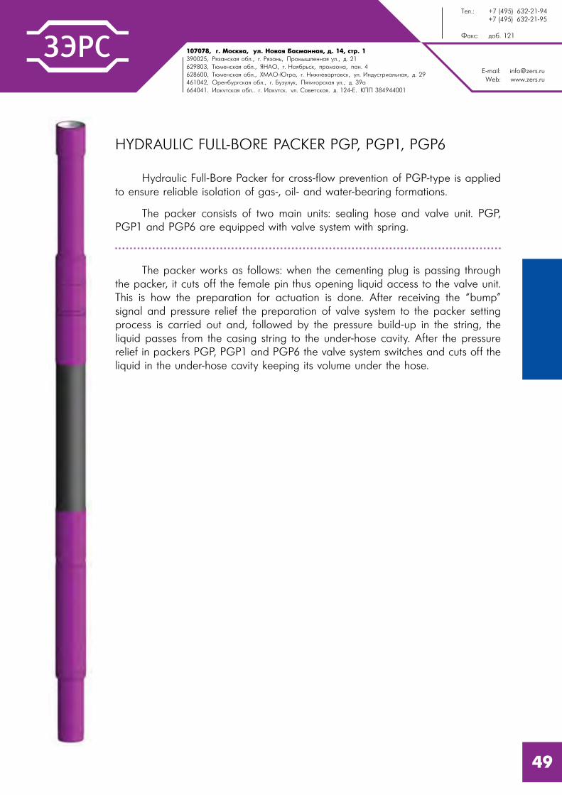
HYDRAULIC FULL-BORE PACKER PGP, PGP1, PGP6
Hydraulic Full-Bore Packer for cross-flow prevention of PGP-type is applied to ensure reliable isolation of gas-, oil- and water-bearing formations.
The packer consists of two main units: sealing hose and valve unit. PGP, PGP1 and PGP6 are equipped with valve system with spring.
The packer works as follows: when the cementing plug is passing through the packer, it cuts off the female pin thus opening liquid access to the valve unit. This is how the preparation for actuation is done. After receiving the “bump” signal and pressure relief the preparation of valve system to the packer setting process is carried out and, followed by the pressure build-up in the string, the liquid passes from the casing string to the under-hose cavity. After the pressure relief in packers PGP, PGP1 and PGP6 the valve system switches and cuts off the liquid in the under-hose cavity keeping its volume under the hose.
49

E-mail: [email protected]: www.zers.ru
Tel.: +7 (495) 632-21-94 +7 (495) 632-21-95
Fax: ext. 121
107078, Moscow, Novaya Basmannaya str., 14-1390025, Ryazan Region, Ryazan, Promyshlennaya str., 21629803, Tyumen Region, YNAD, Noyabrsk, industrial zone, pan. 4628600, Tyumen Region, KMAD-Yugra, Nijnevartovsk, Industrialnaya str., 29461042, Orenburg Region, Buzuluk, Pyatigorskaya str., 39a build664041, Irkutsk Region, Irkutsk, Sovetskaya str., 124-e, RVC 384944001
PARAMETER DESCRIPTION
VALUE
PG
P89
(PG
PU89)
PG
P102/8
9
(PG
PU 1
02/8
9)
PG
P1.1
14
(PG
PU1.1
14)
PG
P127
PG
P6.1
46
(-01)
PG
P1.1
68
(PG
P6.1
68)
PG
P178
Casing string (liner) nominal diameter equipped with the packer, mm
89 102 114 127 146 168 178
Open borehole nominal diameter (bit diameter) which the packer is RIH, mm
120,6 124 146 152,4 215,9 215,9 215,9
Maximum differential pressure between the isolated zones at nominal packer setting coefficient, MPa
15
Length of the well zone overlapped by a packer sealing element, mm
2900(1200)
29001120(2820)
1120 1120
Packer setting coefficient:-nominal-maximum
1,121,25
1,111,3
1,11,3
1,071,25
1,231,45
1,11,4
1,091,4
Maximum operating temperature1, °C
100
Maximum internal overpressure on the packer body, MPa
25
Maximum tensile axial force on the body2, kN
500 600 700 800 850 1200 1100
Drift diameter, after actuation, mm
75,9 88 99 105,6 129 150,5 157
Outer diameter, mm 108 118 134 142 180 197 203
Length, not more:- in operating position, mm
5374(3724)
5431(3610)
5396(3696)
56004088(5908)
4503(4423)
4247
Weight, not more:- in operating position, kg
108(77,9)
137(116)
124,7(96,6)
178,6185,6(247)
220 (213)
250
1 Reference only, depends on operating conditions of general mechanical rubber goods in a well.2 Calculated value when stresses reach yield point of the material.
50

107078, �. l%“*"=, 3�. m%"= a=“�=……= , . 14, “2!. 1390025, p ƒ=…“*= %K�., . p ƒ=…�, o!%/���……= 3�., �. 21629803, Š��…“*= %K�., “m`n, . m% K!�“*, C!%ƒ%…=, C=…. 4628600, Š��…“*= %K�., ul`n-~ !=, . m,›…�"=!2%"“*, 3�. h…�3“2!,=��…= , �. 29461042, n!�…K3! “*= %K�., . a3ƒ3�3*, o 2, %!“*= 3�., �. 39=664041, h!*32“*= %K�., . h!*32“*, 3�. q%"�2“*= , �. 124-e, joo 384944001
E-mail: [email protected]: www.zers.ru
Š��.: +7 (495) 632-21-94 +7 (495) 632-21-95
t=*“: �%K. 121
CROSS-FLOW SEALING PACKER PGMP
Cross-flow Sealing Packer of PGMP-type is applied to ensure reliable isolation of gas-, oil- and water-bearing formations in conditions where the well level is not at the wellhead.
The packer consists of two main units: sealing ring and protection unit against premature actuation.
The packer works as follows: when the cementing plug is passing through the packer, it cuts off the female pin opening thus liquid access to the thruster. This is how the preparation for actuation is done. After receiving the “bump” signal and string pressure build-up till the shear bolts failure level (which is set by selecting the required number of shear bolts before the packer RIH). The thruster starts to move deforming the sealing rings in the axial direction and pressing them against the borehole walls. The movement of the thruster is fixed by a latch.
PARAMETER DESCRIPTION
VALUE
PGMP.168 PGMP.245
Casing string (liner) nominal diameter equipped with the device, mm
102 114
Max. outer diameter, mm 123,8 142
Min. drift diameter after actuation, mm 150,5 224
Maximum tensile axial force on the body, kN1 1500 2000
Internal overpressure for packer actuation, MPa- with all shear bolts
20 15
Maximum pressure differential between t he zones isolated by a packer, MPa
15 12
Maximum internal overpressure on the packer, MPa 25 20
Maximum operating temperature2, °C 100
Length in operating position, mm 2331 2720
Weight in operating position, kg 163 337
Connecting threads:- top and bottom according to GOST 632-80 and GOST R 53365
OTTM-168 OTTM-245
1 Reference only, depends on operating conditions of general mechanical rubber goods in a well.
2 Calculated value when stresses reach yield point of the material.
51

E-mail: [email protected]: www.zers.ru
Tel.: +7 (495) 632-21-94 +7 (495) 632-21-95
Fax: ext. 121
107078, Moscow, Novaya Basmannaya str., 14-1390025, Ryazan Region, Ryazan, Promyshlennaya str., 21629803, Tyumen Region, YNAD, Noyabrsk, industrial zone, pan. 4628600, Tyumen Region, KMAD-Yugra, Nijnevartovsk, Industrialnaya str., 29461042, Orenburg Region, Buzuluk, Pyatigorskaya str., 39a build664041, Irkutsk Region, Irkutsk, Sovetskaya str., 124-e, RVC 384944001
HYDRAULIC FULL-BORE PACKER WITH SMALL-SIZE VALVE UNIT PGPM1.245
Hydraulic Full-Bore Packer for cross-flow prevention of PGPM1 for casing strings 245 mm is applied to ensure reliable isolation of gas-, oil- and water-bearing formations at any depth.
The packer PGPM1 consists of the following main units: body with mounted sealing rubberized fabric unit fixed by steel crimping cups, unit protecting packer from early actuation, valve unit body, valve unit and bottom sub.
The packer works as follows: during the cementing process the cementing plug is passing through the packer interior cavity and cuts off hollow shear pins with a sealing ring thus opening liquid access to the packer valve unit. After receiving the “bump” signal and pressure relief the valve is switched and the preparation of valve system to the packer setting process is carried out and, followed by the pressure build-up in the string, the liquid passes to the under-hose cavity. The overpressure build-up to 6-8 MPa at the packer setting depth leads to inflation of the sealing element which is pressed to the borehole walls hermetically. After the pressure relief the valve system switches and cuts off the liquid in the under-hose cavity keeping its volume under the hose.
52
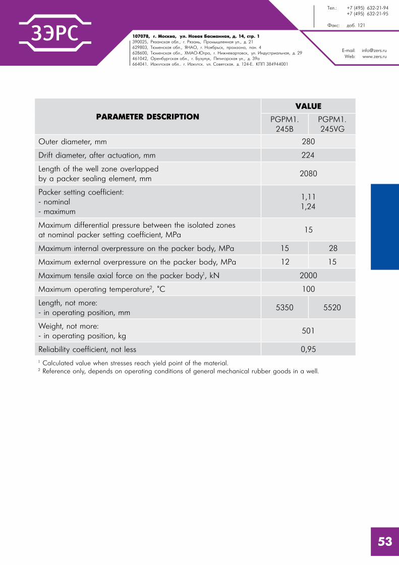
107078, �. l%“*"=, 3�. m%"= a=“�=……= , . 14, “2!. 1390025, p ƒ=…“*= %K�., . p ƒ=…�, o!%/���……= 3�., �. 21629803, Š��…“*= %K�., “m`n, . m% K!�“*, C!%ƒ%…=, C=…. 4628600, Š��…“*= %K�., ul`n-~ !=, . m,›…�"=!2%"“*, 3�. h…�3“2!,=��…= , �. 29461042, n!�…K3! “*= %K�., . a3ƒ3�3*, o 2, %!“*= 3�., �. 39=664041, h!*32“*= %K�., . h!*32“*, 3�. q%"�2“*= , �. 124-e, joo 384944001
E-mail: [email protected]: www.zers.ru
Š��.: +7 (495) 632-21-94 +7 (495) 632-21-95
t=*“: �%K. 121
53
PARAMETER DESCRIPTIONVALUE
PGPM1. 245B
PGPM1. 245VG
Outer diameter, mm 280
Drift diameter, after actuation, mm 224
Length of the well zone overlapped by a packer sealing element, mm
2080
Packer setting coefficient:- nominal- maximum
1,111,24
Maximum differential pressure between the isolated zones at nominal packer setting coefficient, MPa
15
Maximum internal overpressure on the packer body, MPa 15 28
Maximum external overpressure on the packer body, MPa 12 15
Maximum tensile axial force on the packer body1, kN 2000
Maximum operating temperature2, °C 100
Length, not more:- in operating position, mm
5350 5520
Weight, not more:- in operating position, kg
501
Reliability coefficient, not less 0,95
1 Calculated value when stresses reach yield point of the material.2 Reference only, depends on operating conditions of general mechanical rubber goods in a well.

E-mail: [email protected]: www.zers.ru
Tel.: +7 (495) 632-21-94 +7 (495) 632-21-95
Fax: ext. 121
107078, Moscow, Novaya Basmannaya str., 14-1390025, Ryazan Region, Ryazan, Promyshlennaya str., 21629803, Tyumen Region, YNAD, Noyabrsk, industrial zone, pan. 4628600, Tyumen Region, KMAD-Yugra, Nijnevartovsk, Industrialnaya str., 29461042, Orenburg Region, Buzuluk, Pyatigorskaya str., 39a build664041, Irkutsk Region, Irkutsk, Sovetskaya str., 124-e, RVC 384944001
HYDRAULIC PACKER FOR COLLAR CEMENTING PGMC, PGMC2, PGMC4, PGMC6
Hydraulic Packer for Collar Cementing PGMC is applied for collar cementing and to ensure separation of filtering and cementing parts of liners and isolation of gas-, oil- and water-bearing formations.
The packer PGMC consists of two devices combined in one body: a hydraulic packer and a cementing collar. The collar part of the device is the system of mechanically interconnected bushes fixed on shear bolts that overlap cementing slots and the entrance to the under-hose cavity. The design of the packing part is similar to the design of PGP packer.
The packer works as follows: before cementing, a ball is dropped into the transport string and pumped until setting down a seat. With pressure build-up to 4,0 MPa ± 10% bolts are sheared off and the plug is moved down until bumping the shoulder thus opening liquid access to the valve system of the device packer part. After that the pressure is dropped down to 0 and the valve system prepares the packer to actuation. On subsequent pressure build up to 6-8 MPa the hose inflates separating hermetically cementing and noncementing parts of the liner in the outer annular space. The following pressure relief to 0 switches the valve system and shuts liquid access to the packer part of the device.
PGMC2 and PGMC4 packers work in the similar way, but they do not require pressure release for preparation of the valve system for packer setting.
The next cycle of the pressure build-up to 16 (14,5; 14) MPa opening of cementing ports is performed. After mixing and displacing of cement slurry, the hollow cementing plug (together with the top cementing plug) is set down to the seat and after the internal overpressure build up to 5 MPa it closes cementing ports and fixes its position.
54

107078, �. l%“*"=, 3�. m%"= a=“�=……= , . 14, “2!. 1390025, p ƒ=…“*= %K�., . p ƒ=…�, o!%/���……= 3�., �. 21629803, Š��…“*= %K�., “m`n, . m% K!�“*, C!%ƒ%…=, C=…. 4628600, Š��…“*= %K�., ul`n-~ !=, . m,›…�"=!2%"“*, 3�. h…�3“2!,=��…= , �. 29461042, n!�…K3! “*= %K�., . a3ƒ3�3*, o 2, %!“*= 3�., �. 39=664041, h!*32“*= %K�., . h!*32“*, 3�. q%"�2“*= , �. 124-e, joo 384944001
E-mail: [email protected]: www.zers.ru
Š��.: +7 (495) 632-21-94 +7 (495) 632-21-95
t=*“: �%K. 121
PARAMETER DESCRIPTION
VALUE
PG
MC.8
9(P
GM
CU.8
9)
PG
MC.1
02/8
9(P
GM
CU.1
02/8
9)
PG
MC6.1
14
(PG
MCU6.1
14)
PG
MC.1
27
PG
MC6.1
46
PG
MC1.1
68
PG
MC.1
78
Casing string nominal diameter equipped with the packer, mm
89 102 114 127 146 168 178
Open borehole nominal diameter (bit diameter) which the packer is RIH, mm
120,6 123,8 146 152,4 215,9 215,9 215,9
Maximum pressure differential between the isolated zones at nominal packer setting coefficient, MPa
15
Length of the well zone overlapped by a packer sealing element, mm
2900(1200)
2900 1120
Internal overpressure of cementing ports opening1, MPa ± 10%
16 16 15,9 15 15 16 15,6
Internal overpressure of cementing ports closing1, MPa ± 10%
5,0 3 2,9 3,0 2,6 2,5 2,5
Packer setting coefficient:- nominal- maximum
1,121,25
1,111,3
1,111,35
1,111,3
1,181,45
1,131,3
1,131,35
Maximum operating temperature2, °C 100
Maximum tensile axial force on the body3, kN
500 600 700 800 850 1200 950
Drift diameter, after actuation, mm 75,9 88 98,5 105,6 129 150,5 157
Outer diameter, mm 108 118 134 142 180 197 203
Length, not more:- in operating position, mm
5588(3938)
5660(3805)
5645(3945)
5660 5923 5279 5404
1 Controlling overpressure values are given when all the shear bolts on the unit are used.2 Reference only, depends on operating conditions of general mechanical rubber goods in a well.3 Calculated value when stresses reach yield point of the material.
55

E-mail: [email protected]: www.zers.ru
Tel.: +7 (495) 632-21-94 +7 (495) 632-21-95
Fax: ext. 121
107078, Moscow, Novaya Basmannaya str., 14-1390025, Ryazan Region, Ryazan, Promyshlennaya str., 21629803, Tyumen Region, YNAD, Noyabrsk, industrial zone, pan. 4628600, Tyumen Region, KMAD-Yugra, Nijnevartovsk, Industrialnaya str., 29461042, Orenburg Region, Buzuluk, Pyatigorskaya str., 39a build664041, Irkutsk Region, Irkutsk, Sovetskaya str., 124-e, RVC 384944001
PARAMETER DESCRIPTION
VALUE
PGMC2. 102/89
PGMC4.102(PGMCU4.102)
PGMC4.114(PGMCU4.114)
Casing string nominal diameter equipped with the packer, mm
102 114
Open borehole nominal diameter (bit diameter) which the packer is RIH, mm
124 146
Maximum differential pressure between the isolated zones at nominal packer setting coefficient, MPa
15
Length of the well zone overlapped by a packer sealing element, mm
70*3000(1200)
3000(1200)
Internal overpressure of cementing ports opening1, MPa ± 10%
16
Internal overpressure of cementing ports closing1, MPa ± 10%
3 5
Packer setting coefficient:- nominal- maximum
1,061,29
1,071,25
1,141,25
Maximum operating temperature2, °C 100
Maximum tensile axial force on the body3, kN
25
Drift diameter, after actuation, mm 25
Outer diameter, mm 600 600 600
Length, not more:- in operating position, mm
89 85 95
Outer Diameter, mm 118 116 128
Length, not more:- in operating position, mm
28365200(3500)
5271(3571)
1 Actuation pressure with all shear bolts.2 Reference only, depends on operating conditions of general mechanical rubber goods in a well.3 Calculated value.4 Calculated value when stresses reach yield point of the material.* PGMC2.102 packer unit is hydro-mechanical and has two sealing rings.
56

107078, �. l%“*"=, 3�. m%"= a=“�=……= , . 14, “2!. 1390025, p ƒ=…“*= %K�., . p ƒ=…�, o!%/���……= 3�., �. 21629803, Š��…“*= %K�., “m`n, . m% K!�“*, C!%ƒ%…=, C=…. 4628600, Š��…“*= %K�., ul`n-~ !=, . m,›…�"=!2%"“*, 3�. h…�3“2!,=��…= , �. 29461042, n!�…K3! “*= %K�., . a3ƒ3�3*, o 2, %!“*= 3�., �. 39=664041, h!*32“*= %K�., . h!*32“*, 3�. q%"�2“*= , �. 124-e, joo 384944001
E-mail: [email protected]: www.zers.ru
Š��.: +7 (495) 632-21-94 +7 (495) 632-21-95
t=*“: �%K. 121
COLLAR CEMENTING PACKER PMC, PMC-R
Collar Cementing Packer PMC is applied to ensure separation for cemented and noncemented casing string parts (liner) during collar cementing. The packer is used together with collar cementing valve KMC.
The packer is produced in two designs, PMC and PMC-R that differ in the type of a sealing element:
- in PMC a sealing element consists of three sealing rings;
- in PMC-R a sealing element is a rubberized fabric hose.
The packer is actuated before cementing by a ball-drop and its pumping until setting down a seat inside the packer. This leads to the deformation of a sealing element and packing of annular space between the walls of a well and a casing string (liner).
The packer is equipped with a trip valve which ensures RIH without overflow.
57

E-mail: [email protected]: www.zers.ru
Tel.: +7 (495) 632-21-94 +7 (495) 632-21-95
Fax: ext. 121
107078, Moscow, Novaya Basmannaya str., 14-1390025, Ryazan Region, Ryazan, Promyshlennaya str., 21629803, Tyumen Region, YNAD, Noyabrsk, industrial zone, pan. 4628600, Tyumen Region, KMAD-Yugra, Nijnevartovsk, Industrialnaya str., 29461042, Orenburg Region, Buzuluk, Pyatigorskaya str., 39a build664041, Irkutsk Region, Irkutsk, Sovetskaya str., 124-e, RVC 384944001
PARAMETER DESCRIPTIONVALUE
PMC.102PMC-R.102
(PMCU-R.102)
Outer diameter, mm 118
Drift diameter, after actuation, mm 88
Length of the well zone overlapped by a packer sealing element, mm
280 2800 (1200)
Packer setting coefficient:- nominal- maximum
1,061,29
1,111,3
Maximum pressure differential between the isolated zones at nominal packer setting coefficient, MPa
15
Maximum internal overpressure on the packer body, MPa 25
Maximum tensile axial force on the packer body1, kN 600
Maximum operating temperature2, °C 100
Length, not more:- in operating position, mm
1416 4991 (3291)
Weight, not more:- in operating position, kg
45 104 (91)
Reliability coefficient, not less 0,95
1 Calculated value when stresses reach yield point of the material.2 Reference only, depends on operating conditions of general mechanical rubber goods in a well.
58

107078, �. l%“*"=, 3�. m%"= a=“�=……= , . 14, “2!. 1390025, p ƒ=…“*= %K�., . p ƒ=…�, o!%/���……= 3�., �. 21629803, Š��…“*= %K�., “m`n, . m% K!�“*, C!%ƒ%…=, C=…. 4628600, Š��…“*= %K�., ul`n-~ !=, . m,›…�"=!2%"“*, 3�. h…�3“2!,=��…= , �. 29461042, n!�…K3! “*= %K�., . a3ƒ3�3*, o 2, %!“*= 3�., �. 39=664041, h!*32“*= %K�., . h!*32“*, 3�. q%"�2“*= , �. 124-e, joo 384944001
E-mail: [email protected]: www.zers.ru
Š��.: +7 (495) 632-21-94 +7 (495) 632-21-95
t=*“: �%K. 121
WATER-SWELLABLE AND OIL-SWELLABLE PACKER PNV AND PNN
“NTC “ZERS” LLC has developed different packer models in which the sealing element is made of elastomeric material that is able to swell out on contact with certain fluid (water or oil).
Swellable packers have the following significant advantages:
- secure and irreversible beds isolation at well construction;
- packer design doesn’t include valve systems and moving parts which can cause the packer failure;
- there is no need in special operations and special running tool for their installation in the well;
- ability to self-healing and recovery of the sealing properties.
……………………………………………………………………………………………….......
Packers with elastomeric material which swell in hydrocarbon medium are marked as PNN, and packers with elastomeric material which swell in water medium are marked as PNV.
PNV and PNN packers can be installed with the casing string as well as in the hole open bore, they can be applied at various stages of well construction including fixing of the lateral holes as the redundant device for increasing of lateral holes fixing quality at the space between a liner hanger and a port made in a production string.
Packers with sealing elements made of swellable elastomeric materials can also be used for effective and secure beds isolation at construction of horizontal and multilateral wells, for improvement of cementing quality, in complexes for controlled zonal isolation with FSO filters and KRR devices, as well as in many other operations at wells fixing and zonal isolation.
PNV and PNN swellable packer models are designed for space isolation in an open hole or in a casing string.
59

E-mail: [email protected]: www.zers.ru
Tel.: +7 (495) 632-21-94 +7 (495) 632-21-95
Fax: ext. 121
107078, Moscow, Novaya Basmannaya str., 14-1390025, Ryazan Region, Ryazan, Promyshlennaya str., 21629803, Tyumen Region, YNAD, Noyabrsk, industrial zone, pan. 4628600, Tyumen Region, KMAD-Yugra, Nijnevartovsk, Industrialnaya str., 29461042, Orenburg Region, Buzuluk, Pyatigorskaya str., 39a build664041, Irkutsk Region, Irkutsk, Sovetskaya str., 124-e, RVC 384944001
PARAMETER DESCRIPTION
PNV AND PNN PACKER TYPICAL SIZE
102/1
18
102/1
24
114/1
36
114/1
44
114/1
48
127/1
48
Liner nominal diameter on which the packer is RIH, mm
102 102 114 114 114 127
Recommended wellbore diameter which the packer is installed in, mm
124...128 132 143…146 152…156 156…160 156…160
Maximum pressure differential on the packer, MPa
70
Elastomeric material length, mm
1200
Packer length, mm 2600
Packer outer diameter, mm 118 124 136 144 148 148
Weight, kg 58 61 72 75 78 81
Maximum operating temperature, °C
100
Estimated packer swelling time for full isolation of the well space1, days
5…7 7…9
1 Parameters values are shown for the rated hole diameter on the base of used swelling resins types and well conditions (temperature, well fluid type on running down and operation, etc.).
60


CASING HARDWAREIII
626466686970727476777980818384868788899093
Collar for Collar Cementing MMC1 . . . . . . . . . . . . . . . . . . . . . . . . . . .String Disconnect for Water Wells RKVS . . . . . . . . . . . . . . . . . . . . . . . .Multiple-Unit Rotating Disconnect RKVO . . . . . . . . . . . . . . . . . . . . . . . .Collar Cementing Valve KMC . . . . . . . . . . . . . . . . . . . . . . . . . . . . . . .Cementing Basket CK . . . . . . . . . . . . . . . . . . . . . . . . . . . . . . . . . . . . .Pressure Test Device PO . . . . . . . . . . . . . . . . . . . . . . . . . . . . . . . . . . .Stage-by-stage Casing Running Tool USSK, USSKP . . . . . . . . . . . . . . . .Hydraulic Fracturing Sealing Assembly UGRH . . . . . . . . . . . . . . . . . . . .Screener UECS . . . . . . . . . . . . . . . . . . . . . . . . . . . . . . . . . . . . . . . . .Ball Check Valve KOSH2, KOSHBT . . . . . . . . . . . . . . . . . . . . . . . . . . .Seat-Trap SL . . . . . . . . . . . . . . . . . . . . . . . . . . . . . . . . . . . . . . . . . . . .Auxiliary Top Modular Packer PDV-M . . . . . . . . . . . . . . . . . . . . . . . . . .Top Auxiliary Packer PDV2 . . . . . . . . . . . . . . . . . . . . . . . . . . . . . . . . .Trip Stop-Tap CPD2 . . . . . . . . . . . . . . . . . . . . . . . . . . . . . . . . . . . . . .Bow-Spring Centralizer PC . . . . . . . . . . . . . . . . . . . . . . . . . . . . . . . . .Hard Elastic Centralizer PCR . . . . . . . . . . . . . . . . . . . . . . . . . . . . . . . .Low-frictional Turbulence Generating Centralizer CTN . . . . . . . . . . . . . .Stop Ring SKC . . . . . . . . . . . . . . . . . . . . . . . . . . . . . . . . . . . . . . . . . .Cementing Throttle Check Valve CKOD . . . . . . . . . . . . . . . . . . . . . . . .Casing Shoe BK . . . . . . . . . . . . . . . . . . . . . . . . . . . . . . . . . . . . . . . . .Well Screen FS, FB . . . . . . . . . . . . . . . . . . . . . . . . . . . . . . . . . . . . . . .
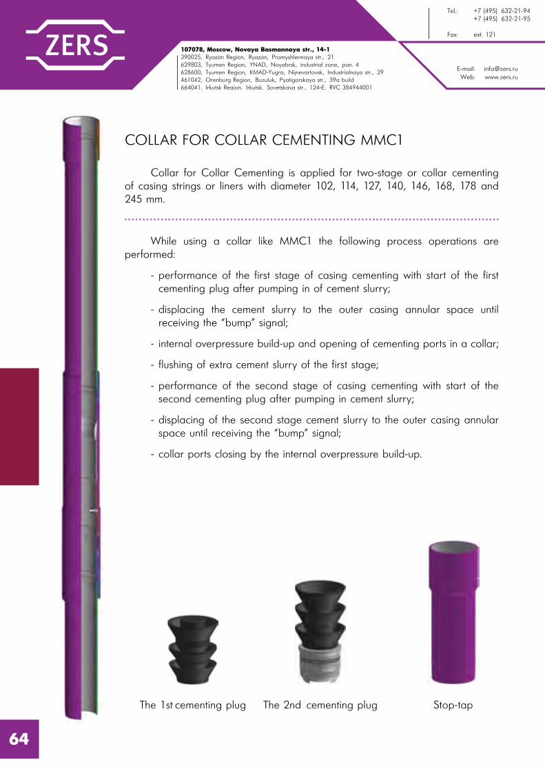
E-mail: [email protected]: www.zers.ru
Tel.: +7 (495) 632-21-94 +7 (495) 632-21-95
Fax: ext. 121
107078, Moscow, Novaya Basmannaya str., 14-1390025, Ryazan Region, Ryazan, Promyshlennaya str., 21629803, Tyumen Region, YNAD, Noyabrsk, industrial zone, pan. 4628600, Tyumen Region, KMAD-Yugra, Nijnevartovsk, Industrialnaya str., 29461042, Orenburg Region, Buzuluk, Pyatigorskaya str., 39a build664041, Irkutsk Region, Irkutsk, Sovetskaya str., 124-e, RVC 384944001
COLLAR FOR COLLAR CEMENTING MMC1
Collar for Collar Cementing is applied for two-stage or collar cementing of casing strings or liners with diameter 102, 114, 127, 140, 146, 168, 178 and 245 mm.
While using a collar like MMC1 the following process operations are performed:
- performance of the first stage of casing cementing with start of the first cementing plug after pumping in of cement slurry;
- displacing the cement slurry to the outer casing annular space until receiving the “bump” signal;
- internal overpressure build-up and opening of cementing ports in a collar;
- flushing of extra cement slurry of the first stage;
- performance of the second stage of casing cementing with start of the second cementing plug after pumping in cement slurry;
- displacing of the second stage cement slurry to the outer casing annular space until receiving the “bump” signal;
- collar ports closing by the internal overpressure build-up.
The 2nd cementing plugThe 1st cementing plug Stop-tap
64

107078, �. l%“*"=, 3�. m%"= a=“�=……= , . 14, “2!. 1390025, p ƒ=…“*= %K�., . p ƒ=…�, o!%/���……= 3�., �. 21629803, Š��…“*= %K�., “m`n, . m% K!�“*, C!%ƒ%…=, C=…. 4628600, Š��…“*= %K�., ul`n-~ !=, . m,›…�"=!2%"“*, 3�. h…�3“2!,=��…= , �. 29461042, n!�…K3! “*= %K�., . a3ƒ3�3*, o 2, %!“*= 3�., �. 39=664041, h!*32“*= %K�., . h!*32“*, 3�. q%"�2“*= , �. 124-e, joo 384944001
E-mail: [email protected]: www.zers.ru
Š��.: +7 (495) 632-21-94 +7 (495) 632-21-95
t=*“: �%K. 121
PARAMETER DESCRIPTION
VALUE
MM
C1.1
02
MM
C1.1
14
MM
C1.1
27
MM
C1.1
40
MM
C1.1
46
MM
C1.1
68
MM
C1.1
78
MM
C1.2
45
Casing string nominal diameter equipped and RIH with the collar, mm
102 114 127 140 146 168 178 245
Open borehole nominal diameter (bit diameter) which the collar is run in, mm
124 142,9 155,6 190,5 190,5 215,9 215,9 295,3
Maximum outer diameter, mm 120 136 148 172 178 197 204 282
Drift diameter, after actuation, mm 88 98 110 124 130 150 158 220
Internal overpressure of cementing ports opening1, MPa ± 10%
16,0 16,0 14,0 16,0 16,0 16,0 16,0 14,0
Internal overpressure of cementing ports closing1, MPa ± 10%
3,5 2,2 2,0 4,0 5,0 5,0 4,0 3,5
Maximum operating temperature2, °C
100
Maximum internal overpressure on the collar housing, MPa
25
Maximum external overpressure on the collar housing3, MPa
35,0 35,0 18,0 18,0 18,0 18,0 18,0 19,0
Maximum tensile axial force on the collar housing3, kN
600 700 800 1000 1000 1200 1200 2300
Length in operating position, mm 1013 1990 2299 2865 2865 2888 2865 2333
Weight in operating position, kg 29,1 67,5 95 118 122 134 150 2651 Actuation pressure with all the shear bolts.2 Reference only, depends on operating conditions of general mechanical rubber goods in a well.3 Calculated value.
65

E-mail: [email protected]: www.zers.ru
Tel.: +7 (495) 632-21-94 +7 (495) 632-21-95
Fax: ext. 121
107078, Moscow, Novaya Basmannaya str., 14-1390025, Ryazan Region, Ryazan, Promyshlennaya str., 21629803, Tyumen Region, YNAD, Noyabrsk, industrial zone, pan. 4628600, Tyumen Region, KMAD-Yugra, Nijnevartovsk, Industrialnaya str., 29461042, Orenburg Region, Buzuluk, Pyatigorskaya str., 39a build664041, Irkutsk Region, Irkutsk, Sovetskaya str., 124-e, RVC 384944001
66
STRING DISCONNECT FOR WATER WELLS RKVS
Disconnect RKVS is used to disconnect the transport string while RIH the flush casing (liner). RKVS 168/324 is applied in holes with casing strings which diameter is 324 mm where liners of casing pipes with diameter 168 mm are run in.
While using a disconnect RKVS 168/324 the following process operations are performed:
- the disconnect RKVS 168/324 and the provided tool set (accessories) are run in as a part of a liner 168 mm on a flush transport pipe string with inner diameter not less than 150 mm;
- performance of the liner cementing with start of the cementing plug after pumping in of cement slurry for its separation from the displacement fluid;
- displacing the cement slurry to the outer casing annular space until receiving the “bump” signal;
- disconnect off-loading (setting) on funnel which has been mounted in a casing string 324 mm;
- liner disconnection from the transport string by mechanical rotation of the string to the right;
- washover and transport string pulling out.
Disconnect operating medium is drilling mud and cementing slurry treated by chemical reagents, oilfield brine, oil and gas at 100 °C temperature.
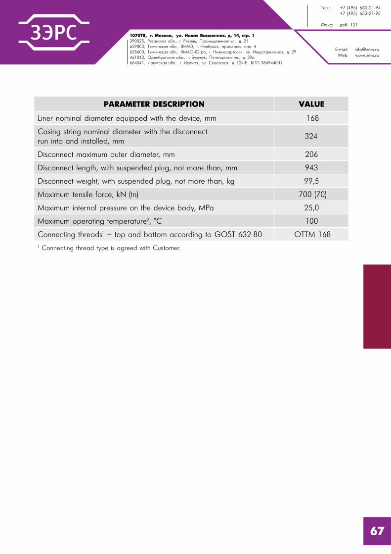
107078, �. l%“*"=, 3�. m%"= a=“�=……= , . 14, “2!. 1390025, p ƒ=…“*= %K�., . p ƒ=…�, o!%/���……= 3�., �. 21629803, Š��…“*= %K�., “m`n, . m% K!�“*, C!%ƒ%…=, C=…. 4628600, Š��…“*= %K�., ul`n-~ !=, . m,›…�"=!2%"“*, 3�. h…�3“2!,=��…= , �. 29461042, n!�…K3! “*= %K�., . a3ƒ3�3*, o 2, %!“*= 3�., �. 39=664041, h!*32“*= %K�., . h!*32“*, 3�. q%"�2“*= , �. 124-e, joo 384944001
E-mail: [email protected]: www.zers.ru
Š��.: +7 (495) 632-21-94 +7 (495) 632-21-95
t=*“: �%K. 121
67
PARAMETER DESCRIPTION VALUE
Liner nominal diameter equipped with the device, mm 168
Casing string nominal diameter with the disconnect run into and installed, mm
324
Disconnect maximum outer diameter, mm 206
Disconnect length, with suspended plug, not more than, mm 943
Disconnect weight, with suspended plug, not more than, kg 99,5
Maximum tensile force, kN (tn) 700 (70)
Maximum internal pressure on the device body, MPa 25,0
Maximum operating temperature2, °C 100
Connecting threads1 – top and bottom according to GOST 632-80 ОТТМ 168
1 Connecting thread type is agreed with Customer.

E-mail: [email protected]: www.zers.ru
Tel.: +7 (495) 632-21-94 +7 (495) 632-21-95
Fax: ext. 121
107078, Moscow, Novaya Basmannaya str., 14-1390025, Ryazan Region, Ryazan, Promyshlennaya str., 21629803, Tyumen Region, YNAD, Noyabrsk, industrial zone, pan. 4628600, Tyumen Region, KMAD-Yugra, Nijnevartovsk, Industrialnaya str., 29461042, Orenburg Region, Buzuluk, Pyatigorskaya str., 39a build664041, Irkutsk Region, Irkutsk, Sovetskaya str., 124-e, RVC 384944001
68
MULTIPLE-UNIT ROTATING DISCONNECT RKVO
Disconnect RKVO is applied for sectional running in of a casing string 168 mm with the option of reaming with rotation and washing out during the first section RIH.
While using a disconnect RKVO 168 the following process operations are performed:
- the disconnect RKVO and the provided tool set (accessories) are run in as a part of a liner 168 mm on a drill pipe string with inner diameter not less than 100 mm;
- reaming with rotation to the right and washing out if necessary;
- performance of the liner cementing with start of the cementing plug after pumping in of cement slurry for its separation from the displacement fluid;
- displacing the cement slurry to the outer casing annular space until receiving the “bump” signal;
- hydraulic disconnection of the section from the drill string through internal overpressure build-up;
- mechanical disconnection by string rotation to the right if hydraulic disconnection is impossible;
- washover and drill string pulling out;
- the second section running in and hermetical connection to the first section;
- cementing ports opening in MMC1.168 collar and the second section cementing with a cementing plug start and closing of ports after receiving the “bump” signal.

107078, �. l%“*"=, 3�. m%"= a=“�=……= , . 14, “2!. 1390025, p ƒ=…“*= %K�., . p ƒ=…�, o!%/���……= 3�., �. 21629803, Š��…“*= %K�., “m`n, . m% K!�“*, C!%ƒ%…=, C=…. 4628600, Š��…“*= %K�., ul`n-~ !=, . m,›…�"=!2%"“*, 3�. h…�3“2!,=��…= , �. 29461042, n!�…K3! “*= %K�., . a3ƒ3�3*, o 2, %!“*= 3�., �. 39=664041, h!*32“*= %K�., . h!*32“*, 3�. q%"�2“*= , �. 124-e, joo 384944001
E-mail: [email protected]: www.zers.ru
Š��.: +7 (495) 632-21-94 +7 (495) 632-21-95
t=*“: �%K. 121
69
PARAMETER DESCRIPTION VALUE
Liner nominal diameter equipped with the device, mm 168
Disconnect maximum outer diameter, mm 203
Drift diameter, after actuation, mm 150
Disconnect length, not more than, mm 1375
Disconnect weight, not more than, kg 171
Maximum tensile force, kN (tn) 1300 (130)
Maximum torque, kN*m 15
Disconnect unit actuation pressure, MPa 18,5
Maximum swinging moment at mechanical disconnection, kg*m 50-70
Maximum internal pressure on the device body, MPa 25,0
Maximum operating temperature2, °C 100
Connecting threads1:- top according to GOST 632-80- bottom
Z-133TMK UP CWB 168
1 Connecting thread type is agreed with Customer.

E-mail: [email protected]: www.zers.ru
Tel.: +7 (495) 632-21-94 +7 (495) 632-21-95
Fax: ext. 121
107078, Moscow, Novaya Basmannaya str., 14-1390025, Ryazan Region, Ryazan, Promyshlennaya str., 21629803, Tyumen Region, YNAD, Noyabrsk, industrial zone, pan. 4628600, Tyumen Region, KMAD-Yugra, Nijnevartovsk, Industrialnaya str., 29461042, Orenburg Region, Buzuluk, Pyatigorskaya str., 39a build664041, Irkutsk Region, Irkutsk, Sovetskaya str., 124-e, RVC 384944001
70
COLLAR CEMENTING VALVE KMC
Collar Cementing Valve is applied for collar cementing of liners and is used as a whole with the packer PMC or PMC-R.
The valve opens hydraulically by pressure build-up. The valve closes automatically at any moment when outer annular pressure is higher than pipe pressure. Final valve closing and fixation in the set position are performed when a cementing plug is set into a seat in the valve.
PARAMETER DESCRIPTIONVALUE
KMC.102 KMC.114
Liner nominal diameter equipped with the device, mm
102 114
Open borehole diameter which the device is run into and installed, mm
123,8-124 142,9
Maximum outer diameter of the device, mm 118 130
Drift diameter of the device (after disconnection), mm
88 99
Length of the device fully assembled, mm, not more
594 670
Device weight, kg, not more than 15,4 20,7
Maximum tensile force at which the stresses in the body parts reach the yield point1, kN (tn)
600 (60) 700 (70)
Cementing ports opening pressure2, MPa ±10%
16,0
Maximum operating temperature3, °C 100
Connecting threads4:- top according to TU 14-161-163-96 (GOST 632-80)
- bottom according to TU 14-161-163-96 (GOST 632-80)
ОТТМ 102
ОТТМ 102
ОТТМ 114
ОТТМ 114
1 Calculated value when stresses reach yield point of the material.2 Actuation pressure with all shear bolts.3 Reference only, depends on operating conditions of general mechanical rubber goods in a well.
4 Connecting thread type is agreed with the Customer.

107078, �. l%“*"=, 3�. m%"= a=“�=……= , . 14, “2!. 1390025, p ƒ=…“*= %K�., . p ƒ=…�, o!%/���……= 3�., �. 21629803, Š��…“*= %K�., “m`n, . m% K!�“*, C!%ƒ%…=, C=…. 4628600, Š��…“*= %K�., ul`n-~ !=, . m,›…�"=!2%"“*, 3�. h…�3“2!,=��…= , �. 29461042, n!�…K3! “*= %K�., . a3ƒ3�3*, o 2, %!“*= 3�., �. 39=664041, h!*32“*= %K�., . h!*32“*, 3�. q%"�2“*= , �. 124-e, joo 384944001
E-mail: [email protected]: www.zers.ru
Š��.: +7 (495) 632-21-94 +7 (495) 632-21-95
t=*“: �%K. 121
CEMENTING BASKET CK
Cementing Basket is used to create a platform for sedimentation of cement slurry filling outer annular space outside a casing diameter 102, 114, 127, 140, 146, 168 and 178 mm.
During cement slurry squeezing a cementing plug goes through the inner hollow of the device and disengages the early actuation protection. After receiving the “bump” signal and the check valve leakage test the internal pressure is build-up to the actuation pressure of the device preset before the device RIH. Shear bolts are destroyed and actuation starts. Petal shell is outstretched and touches the hole wall thus constructing a base for sedimentation of cement slurry solid phase. Condensed cement connecting strip is formed by itself on it thus preventing lowering of the cement slurry column in the hole.
PARAMETER DESCRIPTION
VALUE
CK.102
/140
CK.114
CK.127
CK.140
CK.146
CK.168
CK.178
Maximum outer diameter, mm 117 130 144 163 170 193 200
Casing string diameter equipped and RIH with the device, mm
101,6 114,3 127 139,7 146,1 168 178
Drift diameter, after actuation, mm 89 99 112 126 127 150 162
Device actuation pressure1, MPa 16 16 16 16 16 16 16
Maximum diameter of basket opening, mm
185 195 195 205 240 250 260
Length, mm 955 1050 1050 1150 1150 1150 1150
Weight, kg, not more 29 31 34 52 55,5 65,5 69
Maximum operating temperature2, °C 100 100 100 100 100 100 1001 Actuation pressure when all the shear bolts.2 Reference only, depends on operating conditions of general mechanical rubber goods in a well.
71
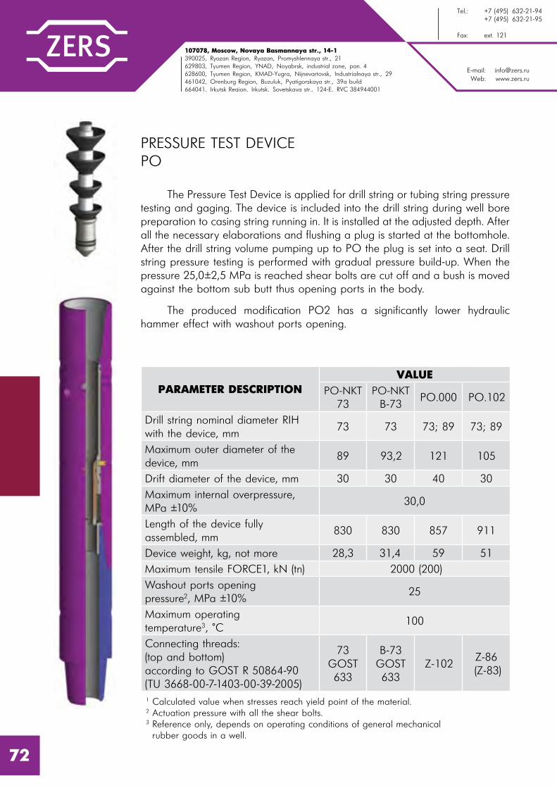
E-mail: [email protected]: www.zers.ru
Tel.: +7 (495) 632-21-94 +7 (495) 632-21-95
Fax: ext. 121
107078, Moscow, Novaya Basmannaya str., 14-1390025, Ryazan Region, Ryazan, Promyshlennaya str., 21629803, Tyumen Region, YNAD, Noyabrsk, industrial zone, pan. 4628600, Tyumen Region, KMAD-Yugra, Nijnevartovsk, Industrialnaya str., 29461042, Orenburg Region, Buzuluk, Pyatigorskaya str., 39a build664041, Irkutsk Region, Irkutsk, Sovetskaya str., 124-e, RVC 384944001
PRESSURE TEST DEVICE PO
The Pressure Test Device is applied for drill string or tubing string pressure testing and gaging. The device is included into the drill string during well bore preparation to casing string running in. It is installed at the adjusted depth. After all the necessary elaborations and flushing a plug is started at the bottomhole. After the drill string volume pumping up to PO the plug is set into a seat. Drill string pressure testing is performed with gradual pressure build-up. When the pressure 25,0±2,5 MPa is reached shear bolts are cut off and a bush is moved against the bottom sub butt thus opening ports in the body.
The produced modification PO2 has a significantly lower hydraulic hammer effect with washout ports opening.
PARAMETER DESCRIPTIONVALUE
PO-NKT 73
PO-NKT В-73
PO.000 PO.102
Drill string nominal diameter RIH with the device, mm
73 73 73; 89 73; 89
Maximum outer diameter of the device, mm
89 93,2 121 105
Drift diameter of the device, mm 30 30 40 30
Maximum internal overpressure, MPa ±10%
30,0
Length of the device fully assembled, mm
830 830 857 911
Device weight, kg, not more 28,3 31,4 59 51
Maximum tensile FORCE1, kN (tn) 2000 (200)
Washout ports opening pressure2, MPa ±10%
25
Maximum operating temperature3, °C
100
Connecting threads:(top and bottom)according to GOST R 50864-90(TU 3668-00-7-1403-00-39-2005)
73 GOST 633
В-73 GOST 633
Z-102Z-86 (Z-83)
1 Calculated value when stresses reach yield point of the material.2 Actuation pressure with all the shear bolts.3 Reference only, depends on operating conditions of general mechanical rubber goods in a well.
72

107078, �. l%“*"=, 3�. m%"= a=“�=……= , . 14, “2!. 1390025, p ƒ=…“*= %K�., . p ƒ=…�, o!%/���……= 3�., �. 21629803, Š��…“*= %K�., “m`n, . m% K!�“*, C!%ƒ%…=, C=…. 4628600, Š��…“*= %K�., ul`n-~ !=, . m,›…�"=!2%"“*, 3�. h…�3“2!,=��…= , �. 29461042, n!�…K3! “*= %K�., . a3ƒ3�3*, o 2, %!“*= 3�., �. 39=664041, h!*32“*= %K�., . h!*32“*, 3�. q%"�2“*= , �. 124-e, joo 384944001
E-mail: [email protected]: www.zers.ru
Š��.: +7 (495) 632-21-94 +7 (495) 632-21-95
t=*“: �%K. 121
PARAMETER DESCRIPTIONVALUE
PO2.102 PO.114 PO.127
Drill string nominal diameter RIH with the device, mm
73, 89 114 127
Maximum outer diameter of the device, mm 105 158,8 158,8
Drift diameter of the device, mm 30 55 55
Maximum internal overpressure, MPa ±10% 30 30 30
Length of the device fully assembled, mm 826 1437 1091
Device weight, kg, not more 42,2 155,3 118,3
Maximum tensile FORCE1, kN (tn) 2000 (200)
Washout ports opening pressure2, MPa ±10%
25 25 25
Maximum operating temperature3, °C
100
Connecting threads:(top and bottom)according to GOST R 50864-90(TU 3668-00-7-1403-00-39-2005)
Z-86Z-83
Z-122(Z-133)
Z-133
1 Calculated value when stresses reach yield point of the material.2 Actuation pressure with all the shear bolts.3 Reference only, depends on operating conditions of general mechanical rubber goods in a well.
73

E-mail: [email protected]: www.zers.ru
Tel.: +7 (495) 632-21-94 +7 (495) 632-21-95
Fax: ext. 121
107078, Moscow, Novaya Basmannaya str., 14-1390025, Ryazan Region, Ryazan, Promyshlennaya str., 21629803, Tyumen Region, YNAD, Noyabrsk, industrial zone, pan. 4628600, Tyumen Region, KMAD-Yugra, Nijnevartovsk, Industrialnaya str., 29461042, Orenburg Region, Buzuluk, Pyatigorskaya str., 39a build664041, Irkutsk Region, Irkutsk, Sovetskaya str., 124-e, RVC 384944001
STAGE-BY-STAGE CASING RUNNING TOOL USSK, USSKP
Stage-by-stage RIH of liners appeared firstly as a practical solution for the problem of casing strings running into wells with intensive curvature and (or) long horizontal section thus there is always a risk not to reach the target depth while running in a liner. Secondly it appeared as a possibility to perform a liner collar cementing at a given interval by cementing its second section.
The stage-by-stage-casing (liners) running tool USSK is intended for running in of a liner first (lower) section on drill pipes without its cementing with further running in, leaktight connection of the liner second section followed by cementing of the second section. USSK is threaded onto the upper pipe of the liner first section and is RIH on drill pipes.
USSK consists of two principal units: hydraulic disconnection unit to disconnect the liner from a transport string and mechanical disconnection (back off) unit to disconnect the liner from a transport string implemented in a single tool. After liner running into the adjusted depth and a ball is dropped into the transport string and pumped until setting down a seat. Pumping screws are cut by the pressure build-up to 14 MPa and the liner hydraulic disconnection unit is actuated. If there is no possibility for the internal overpressure build-up, the disconnection is performed by rotating (20 rotations) of the transport string to the right.
The stage-by-stage-casing (liners) running tool with packer sealing USSKP.
The USSKP consists of three principal tools: hydraulic inflatable packer unit, hydraulic disconnection unit to disconnect the liner from the transport string and mechanical disconnection (back off) unit to disconnect the liner from the transport string implemented in a single tool.
74

107078, �. l%“*"=, 3�. m%"= a=“�=……= , . 14, “2!. 1390025, p ƒ=…“*= %K�., . p ƒ=…�, o!%/���……= 3�., �. 21629803, Š��…“*= %K�., “m`n, . m% K!�“*, C!%ƒ%…=, C=…. 4628600, Š��…“*= %K�., ul`n-~ !=, . m,›…�"=!2%"“*, 3�. h…�3“2!,=��…= , �. 29461042, n!�…K3! “*= %K�., . a3ƒ3�3*, o 2, %!“*= 3�., �. 39=664041, h!*32“*= %K�., . h!*32“*, 3�. q%"�2“*= , �. 124-e, joo 384944001
E-mail: [email protected]: www.zers.ru
Š��.: +7 (495) 632-21-94 +7 (495) 632-21-95
t=*“: �%K. 121
PARAMETER DESCRIPTIONVALUE
USSK 102 USSK 114
Liner nominal diameter equipped with the device, mm 102 114
Open borehole diameter which the device is run into and installed, mm
123,8-124 142,9
Maximum outer diameter of the device, mm 118 132
Drift diameter of the device (after disconnection), mm 88 99
Length of the device fully assembled, mm, not more 2381 2416
Device weight, kg, not more 60 98,1
Maximum tensile force at which the stresses in the body parts reach the yield POINT1, kN (tn)
600 (60) 700 (70)
Disconnection unit actuation pressure2, MPa ±10% 13,0
Maximum operating temperature3, °C 100
Connecting threads4:- top according to GOST 28487-90- bottom according to TU 14-161-163-96 (GOST 632-80)
Z-86ОТТМ 102
Z-102ОТТМ 114
1 Calculated value when stresses reach yield point of the material.
2 Actuation pressure with all shear bolts.
3 Reference only, depends on operating conditions of general mechanical rubber goods in a well.
STABBING SHOEUSSK
102.100USSK
114.100
Maximum outer diameter of the device, mm 117 127
Drift diameter of the device, mm 88 99
Minimum load for the device actuation, kg ±10% 2000 2000
Maximum spring to check casing string sections joining, kg 5000 5000
Length of the device fully assembled, mm, not more 250 280
Device weight, kg, not more 6,1 6,4
Top connecting thread according to TU 14-161-163-96 (GOST 632-80)*
ОТТМ 102 ОТТМ 114
* Connecting thread type is agreed with Customer.
75

E-mail: [email protected]: www.zers.ru
Tel.: +7 (495) 632-21-94 +7 (495) 632-21-95
Fax: ext. 121
107078, Moscow, Novaya Basmannaya str., 14-1390025, Ryazan Region, Ryazan, Promyshlennaya str., 21629803, Tyumen Region, YNAD, Noyabrsk, industrial zone, pan. 4628600, Tyumen Region, KMAD-Yugra, Nijnevartovsk, Industrialnaya str., 29461042, Orenburg Region, Buzuluk, Pyatigorskaya str., 39a build664041, Irkutsk Region, Irkutsk, Sovetskaya str., 124-e, RVC 384944001
HYDRAULIC FRACTURING SEALING ASSEMBLY UGRH
Sealing assembly UGHR is applied for protection of production string with nominal diameter 146, 168 and 178 mm from overpressure due to hydraulic fracturing.
The device is used in wells cased with liners diameter 102, 114 and 127 mm run in with hangers PHCZ, PHGMC or PHRC with drift pass inner diameter 89, 99 and 111 mm respectively.
Index “N” in UGRH titles is used to mark a device mounted at a liner hanger head. This device has larger pass comparing to UGRH mounted at the bottom sub.
Hydraulic Fracturing Sealing Assembly UGRH has the following advantages:
- adjustable and easy to use design;
- installation of the device doesn’t require any operations with tubing and overpressure at the wellhead;
- self-sealing elements of the sealing unit hold significant pressure differentials;
- large drift pass allows large-volume hydrofracturing performance and reduces abrasive wear of inner parts surface.
The device consists of a hydraulic anchor, a sub with conical back nut, an extension pipe, a sealing unit and a guide shoe.
76

107078, �. l%“*"=, 3�. m%"= a=“�=……= , . 14, “2!. 1390025, p ƒ=…“*= %K�., . p ƒ=…�, o!%/���……= 3�., �. 21629803, Š��…“*= %K�., “m`n, . m% K!�“*, C!%ƒ%…=, C=…. 4628600, Š��…“*= %K�., ul`n-~ !=, . m,›…�"=!2%"“*, 3�. h…�3“2!,=��…= , �. 29461042, n!�…K3! “*= %K�., . a3ƒ3�3*, o 2, %!“*= 3�., �. 39=664041, h!*32“*= %K�., . h!*32“*, 3�. q%"�2“*= , �. 124-e, joo 384944001
E-mail: [email protected]: www.zers.ru
Š��.: +7 (495) 632-21-94 +7 (495) 632-21-95
t=*“: �%K. 121
PARAMETER DESCRIPTION
VALUE
UG
RH.1
02/1
40
UG
RH.1
02/1
46
UG
RH.1
14/1
68-1
02
UG
RH.1
14/1
68
UG
RH.1
27/1
78-1
14
UG
RH.1
27/1
78
UG
RH.1
02/1
46Н
UG
RH.1
14/1
68Н
UG
RH.1
27/1
78Н
Production string nominal diameter for anchor installation, mm
140 146 168 168 178 178 146 168 178
Inner diameter of hanger mounting seat for installation of a sealing unit, mm
85 89 89 99 99 111 108 122 135
Anchor outer diameter, mm 118 122 141 141 148 148 122 141 148
Drift diameter after actuation, mm 60 60 60 76 76 76 76 96 96
Maximum pressure differential, MPa 70
Maximum operating temperature1, °C 100
Connecting thread according to GOST 633-80
89
1 Reference only, depends on operating conditions of general mechanical rubber goods in a well.
77

E-mail: [email protected]: www.zers.ru
Tel.: +7 (495) 632-21-94 +7 (495) 632-21-95
Fax: ext. 121
107078, Moscow, Novaya Basmannaya str., 14-1390025, Ryazan Region, Ryazan, Promyshlennaya str., 21629803, Tyumen Region, YNAD, Noyabrsk, industrial zone, pan. 4628600, Tyumen Region, KMAD-Yugra, Nijnevartovsk, Industrialnaya str., 29461042, Orenburg Region, Buzuluk, Pyatigorskaya str., 39a build664041, Irkutsk Region, Irkutsk, Sovetskaya str., 124-e, RVC 384944001
SCREENER UECS
UECS is a screener to limit sedimentation processes in cement slurry filling casing outer annulus in a well behind the casing diameter 245, 324 and 426 mm.
UECS device includes a spring petal shell interacting with a screening element which is an easily deformable rubber petal collar. Assembly fixture is implemented as bolts with sharpened end which penetrate the casing pipe surface when screwed in.
When cementing is finished the petal collar and the screener shell are in close contact with each other and with well walls (the noncircular one) and form a base for sedimentation of solids from cement slurry. Condensed cement connecting strip is formed by itself on it thus along with the screener preventing lowering of the cement slurry column in the hole.
PARAMETER DESCRIPTIONVALUE
UECS.245 UECS.324 UECS.426
Maximum outer diameter, mm 400 484 600
Casing string diameter, mm 245 324 426
Length, mm 343 320 360
Weight, kg 14,5 15 16
Maximum operating temperature1, °C 1001 Reference only, depends on operating conditions of general mechanical rubber goods in a well.
78
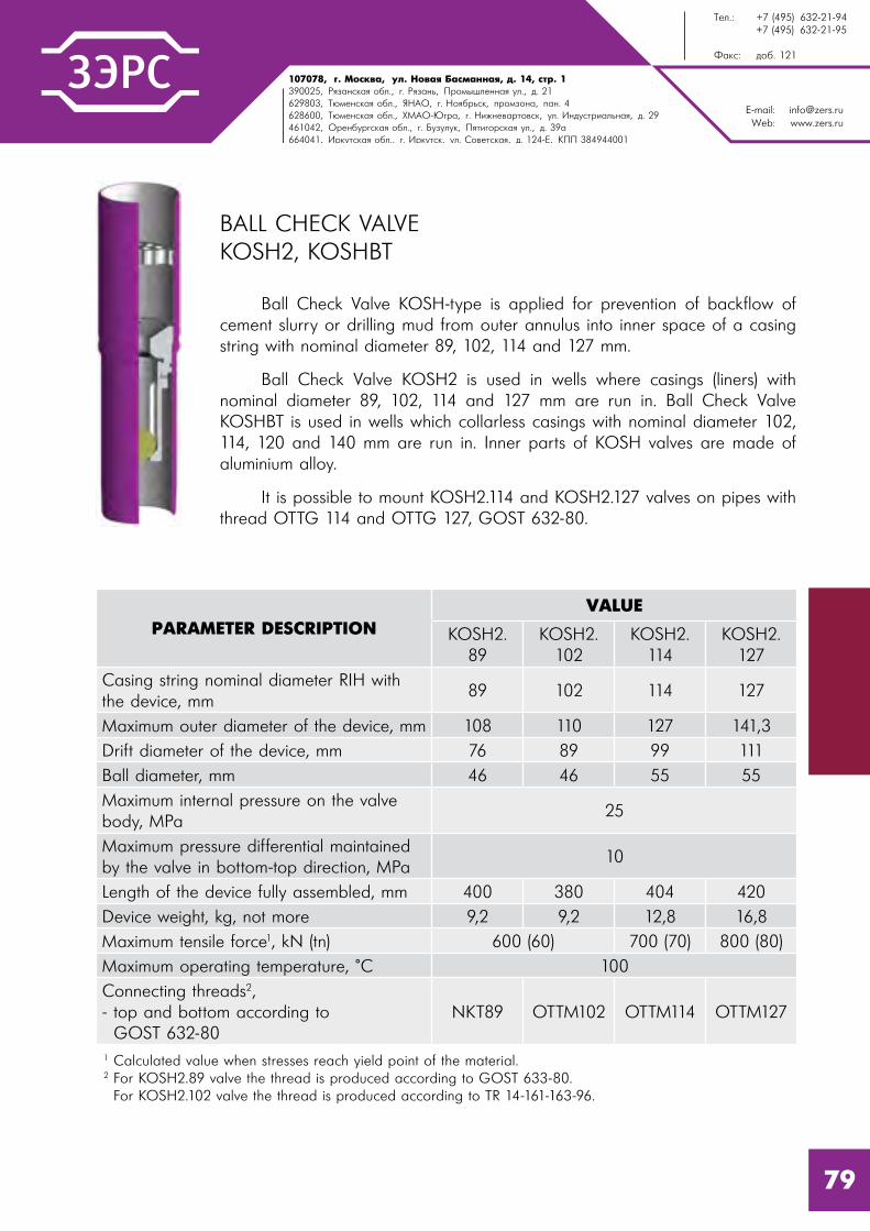
107078, �. l%“*"=, 3�. m%"= a=“�=……= , . 14, “2!. 1390025, p ƒ=…“*= %K�., . p ƒ=…�, o!%/���……= 3�., �. 21629803, Š��…“*= %K�., “m`n, . m% K!�“*, C!%ƒ%…=, C=…. 4628600, Š��…“*= %K�., ul`n-~ !=, . m,›…�"=!2%"“*, 3�. h…�3“2!,=��…= , �. 29461042, n!�…K3! “*= %K�., . a3ƒ3�3*, o 2, %!“*= 3�., �. 39=664041, h!*32“*= %K�., . h!*32“*, 3�. q%"�2“*= , �. 124-e, joo 384944001
E-mail: [email protected]: www.zers.ru
Š��.: +7 (495) 632-21-94 +7 (495) 632-21-95
t=*“: �%K. 121
BALL CHECK VALVE KOSH2, KOSHBT
Ball Check Valve KOSH-type is applied for prevention of backflow of cement slurry or drilling mud from outer annulus into inner space of a casing string with nominal diameter 89, 102, 114 and 127 mm.
Ball Check Valve KOSH2 is used in wells where casings (liners) with nominal diameter 89, 102, 114 and 127 mm are run in. Ball Check Valve KOSHBT is used in wells which collarless casings with nominal diameter 102, 114, 120 and 140 mm are run in. Inner parts of KOSH valves are made of aluminium alloy.
It is possible to mount KOSH2.114 and KOSH2.127 valves on pipes with thread OTTG 114 and OTTG 127, GOST 632-80.
PARAMETER DESCRIPTIONVALUE
KOSH2. 89
KOSH2. 102
KOSH2. 114
KOSH2. 127
Casing string nominal diameter RIH with the device, mm
89 102 114 127
Maximum outer diameter of the device, mm 108 110 127 141,3
Drift diameter of the device, mm 76 89 99 111
Ball diameter, mm 46 46 55 55
Maximum internal pressure on the valve body, MPa
25
Maximum pressure differential maintained by the valve in bottom-top direction, MPa
10
Length of the device fully assembled, mm 400 380 404 420
Device weight, kg, not more 9,2 9,2 12,8 16,8
Maximum tensile force1, kN (tn) 600 (60) 700 (70) 800 (80)
Maximum operating temperature, °C 100
Connecting threads2,- top and bottom according to GOST 632-80
NKT89 ОТТМ102 ОТТМ114 ОТТМ127
1 Calculated value when stresses reach yield point of the material.2 For KOSH2.89 valve the thread is produced according to GOST 633-80. For KOSH2.102 valve the thread is produced according to TR 14-161-163-96.
79

E-mail: [email protected]: www.zers.ru
Tel.: +7 (495) 632-21-94 +7 (495) 632-21-95
Fax: ext. 121
107078, Moscow, Novaya Basmannaya str., 14-1390025, Ryazan Region, Ryazan, Promyshlennaya str., 21629803, Tyumen Region, YNAD, Noyabrsk, industrial zone, pan. 4628600, Tyumen Region, KMAD-Yugra, Nijnevartovsk, Industrialnaya str., 29461042, Orenburg Region, Buzuluk, Pyatigorskaya str., 39a build664041, Irkutsk Region, Irkutsk, Sovetskaya str., 124-e, RVC 384944001
PARAMETER DESCRIPTIONVALUE
KOSHBT. 102
KOSHBT. 114
KOSHBT. 120
KOSHBT. 140
Casing string nominal diameter RIH with the device, mm
102 114 120 140
Maximum outer diameter of the device, mm 103,2 115,2 121,5 140,5
Drift diameter of the device, mm 86,5 98,5 105 124
Ball diameter, mm 46 55
Valve seat hole diameter, mm 30 40
Maximum internal pressure on the valve body, MPa
25
Maximum pressure differential maintained by the valve in bottom-top direction, MPa
10
Length of the device fully assembled, mm 450
Device weight, kg, not more 9,4 11,2 11,97 14,6
Maximum tensile FORCE1, kN (tn) 600 (60) 700 (70) 770 (77) 900 (90)
Maximum operating temperature, °C 100
Connecting threads2,- top and bottom according to TR 14-157-61-99
ТМК-3102
ТМК-3114
ТМК-3120
ТМК-3140
1 Calculated value.2 Reference only, depends on operating conditions of general mechanical rubber goods in a well.3 Connecting thread type is agreed with the Customer.
80

107078, �. l%“*"=, 3�. m%"= a=“�=……= , . 14, “2!. 1390025, p ƒ=…“*= %K�., . p ƒ=…�, o!%/���……= 3�., �. 21629803, Š��…“*= %K�., “m`n, . m% K!�“*, C!%ƒ%…=, C=…. 4628600, Š��…“*= %K�., ul`n-~ !=, . m,›…�"=!2%"“*, 3�. h…�3“2!,=��…= , �. 29461042, n!�…K3! “*= %K�., . a3ƒ3�3*, o 2, %!“*= 3�., �. 39=664041, h!*32“*= %K�., . h!*32“*, 3�. q%"�2“*= , �. 124-e, joo 384944001
E-mail: [email protected]: www.zers.ru
Š��.: +7 (495) 632-21-94 +7 (495) 632-21-95
t=*“: �%K. 121
81
SEAT-TRAP SL
Seat-Trap is applied for accumulation of cementing plugs and seats fragments and to facilitate their following drilling out.
Seat-trap inner parts are made of aluminium alloy.
PARAMETER DESCRIPTIONVALUE
SL.102 SL.114 SL.178
Casing string nominal diameter RIH with the device, mm
102 114 178
Maximum outer diameter of the device, mm 110 127 187
Drift diameter of the device, after drilling, mm 89 99 157
Drift diameter of the device, before drilling, mm 21 28 50
Maximum internal pressure on the body, MPa 70
Length of the device fully assembled, mm 385 420 450
Device weight, kg, not more 7,3 12,3 27
Maximum tensile force1, kN (tn) 600 (60) 700 (70) 1200 (120)
Connecting threads2,- top and bottom according to GOST 632-80
OTTM102 OTTM114 OTTM178
1 Calculated value.2 For SL 102 the connecting thread is made according to TR 14-161-163-96.

E-mail: [email protected]: www.zers.ru
Tel.: +7 (495) 632-21-94 +7 (495) 632-21-95
Fax: ext. 121
107078, Moscow, Novaya Basmannaya str., 14-1390025, Ryazan Region, Ryazan, Promyshlennaya str., 21629803, Tyumen Region, YNAD, Noyabrsk, industrial zone, pan. 4628600, Tyumen Region, KMAD-Yugra, Nijnevartovsk, Industrialnaya str., 29461042, Orenburg Region, Buzuluk, Pyatigorskaya str., 39a build664041, Irkutsk Region, Irkutsk, Sovetskaya str., 124-e, RVC 384944001
AUXILIARY TOP MODULAR PACKER PDV-M
PDV-M device is applied for hermetic connection with a liner “head” run in with the help of hangers PHCZ-type and for additional sealing of a liner “head”.
Besides, the device joint shoe can be used to ensure sealed joint with a liner “head” and if required to build up a liner to fix the leaks above the liner “head”.
The device is RIH on drill pipes and is actuated by the partial tool weight unload. The disconnection is performed automatically at under tension over own weight more than 5 tn
PARAMETER DESCRIPTIONVALUE
PDV-M. 102
PDV-M. 114
PDV-M. 127
Liner nominal diameter equipped with the device, mm 102 114 127
Maximum outer diameter of the device, mm 122 140 149
Drift diameter of the device, mm 89 99 111
Minimum load for the packer actuation, kg 5000
Maximum tension for disconnection, kg 5000
Maximum tensile force1, kN 600 700 800
Maximum pressure differential between the zones isolated by a hydro-mechanical packer, P, MPa
15
Length of the device fully assembled, mm 1430 1485 1720
Device weight, kg, not more 37,4 64 77,4
Maximum operating temperature2, C° 100
Connecting threads:- top according to GOST 28487-90- bottom according to TU 14-161-163
Z-86ОТТМ 102
Z-102ОТТМ 114
Z-102ОТТМ 127
1 Calculated value when stresses reach yield point of the material.2 Reference only, depends on operating conditions of general mechanical rubber goods in a well.
82

107078, �. l%“*"=, 3�. m%"= a=“�=……= , . 14, “2!. 1390025, p ƒ=…“*= %K�., . p ƒ=…�, o!%/���……= 3�., �. 21629803, Š��…“*= %K�., “m`n, . m% K!�“*, C!%ƒ%…=, C=…. 4628600, Š��…“*= %K�., ul`n-~ !=, . m,›…�"=!2%"“*, 3�. h…�3“2!,=��…= , �. 29461042, n!�…K3! “*= %K�., . a3ƒ3�3*, o 2, %!“*= 3�., �. 39=664041, h!*32“*= %K�., . h!*32“*, 3�. q%"�2“*= , �. 124-e, joo 384944001
E-mail: [email protected]: www.zers.ru
Š��.: +7 (495) 632-21-94 +7 (495) 632-21-95
t=*“: �%K. 121
TOP AUXILIARY PACKER PDV-2
PDV-2 device is applied for hermetic connection with a liner “head” run in with the help of hangers PHCZ-type and for additional sealing of a liner “head”.
The device is RIH on drill pipes and is actuated with the partial drilling string weight unload. The disconnection is performed automatically by a drill string pulling out.
PARAMETER DESCRIPTIONVALUE
PDV2.102/146
PDV2.114/168
Liner nominal diameter equipped with the device, mm
102 114
Maximum outer diameter of the device, mm 122 140
Drift diameter of the device, mm 89 99
Minimum load for the packer actuation, kg 5000
Maximum tension for disconnection, kg 5000
Maximum tensile force1, kN 600 600
Maximum pressure differential between the zones isolated by a hydro-mechanical packer, P, MPa
15 15
Length of the device fully assembled, mm 1724 1920
Device weight, kg, not more 62 95
Maximum operating temperature2, °C 100
Connecting threads:- top according to GOST 28487-90 Z-86 Z-1021 Calculated value when stresses reach yield point of the material.2 Reference only, depends on operating conditions of general mechanical rubber goods in a well.
83
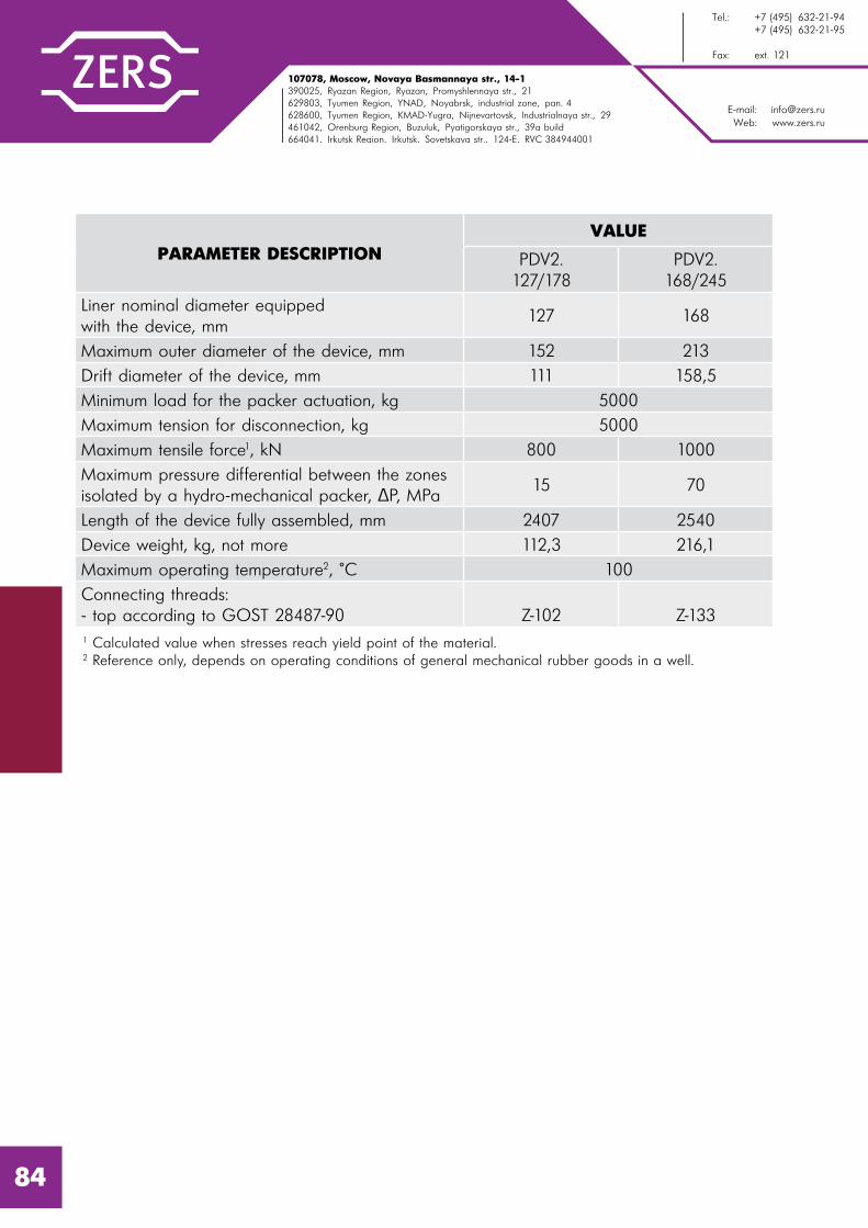
E-mail: [email protected]: www.zers.ru
Tel.: +7 (495) 632-21-94 +7 (495) 632-21-95
Fax: ext. 121
107078, Moscow, Novaya Basmannaya str., 14-1390025, Ryazan Region, Ryazan, Promyshlennaya str., 21629803, Tyumen Region, YNAD, Noyabrsk, industrial zone, pan. 4628600, Tyumen Region, KMAD-Yugra, Nijnevartovsk, Industrialnaya str., 29461042, Orenburg Region, Buzuluk, Pyatigorskaya str., 39a build664041, Irkutsk Region, Irkutsk, Sovetskaya str., 124-e, RVC 384944001
PARAMETER DESCRIPTIONVALUE
PDV2.127/178
PDV2.168/245
Liner nominal diameter equipped with the device, mm
127 168
Maximum outer diameter of the device, mm 152 213
Drift diameter of the device, mm 111 158,5
Minimum load for the packer actuation, kg 5000
Maximum tension for disconnection, kg 5000
Maximum tensile force1, kN 800 1000
Maximum pressure differential between the zones isolated by a hydro-mechanical packer, P, MPa
15 70
Length of the device fully assembled, mm 2407 2540
Device weight, kg, not more 112,3 216,1
Maximum operating temperature2, °C 100
Connecting threads:- top according to GOST 28487-90 Z-102 Z-1331 Calculated value when stresses reach yield point of the material.2 Reference only, depends on operating conditions of general mechanical rubber goods in a well.
84

107078, �. l%“*"=, 3�. m%"= a=“�=……= , . 14, “2!. 1390025, p ƒ=…“*= %K�., . p ƒ=…�, o!%/���……= 3�., �. 21629803, Š��…“*= %K�., “m`n, . m% K!�“*, C!%ƒ%…=, C=…. 4628600, Š��…“*= %K�., ul`n-~ !=, . m,›…�"=!2%"“*, 3�. h…�3“2!,=��…= , �. 29461042, n!�…K3! “*= %K�., . a3ƒ3�3*, o 2, %!“*= 3�., �. 39=664041, h!*32“*= %K�., . h!*32“*, 3�. q%"�2“*= , �. 124-e, joo 384944001
E-mail: [email protected]: www.zers.ru
Š��.: +7 (495) 632-21-94 +7 (495) 632-21-95
t=*“: �%K. 121
TRIP STOP-TAP SPD-2
SPD-2 device is applied for the liner and transport string self-priming in the process of running into a well and receiving the “bump” signal while performing direct cementing during which the hollow cementing plug, as a part of PHCZ or PHGMC liner hanger, together with the upper cementing PCV plug is set into the device seat.
Besides, the device can be applied for actuation of PHRC hanger anchor unit while RIH of a liner with continuous cementing using PHRC hanger.
PARAMETER DESCRIPTIONVALUE
SPD2.102 SPD2.114 SPD2.127
Liner nominal diameter equipped with the device, mm
102 114 127
Maximum outer diameter of the device, mm 114 127 141,3
Drift diameter of the device, mm 88 99 111
Bush shear pressure, MPa± 10% 6,0
Seat shear pressure, MPa± 10% 18,0
Maximum tensile force1, kN 600 700 800
Length of the device fully assembled, mm 721 743 781
Device weight, kg 19,2 24,7 27,6
Maximum operating temperature2, C° 100
Connecting threads according to GOST 632-80 (for SPD2.102 according to TR 14-161-163-96)
OTTM-102 OTTM-114 OTTM-127
1 Calculated value when stresses reach yield point of the material.2 Reference only, depends on operating conditions of general mechanical rubber goods in a well.
85

E-mail: [email protected]: www.zers.ru
Tel.: +7 (495) 632-21-94 +7 (495) 632-21-95
Fax: ext. 121
107078, Moscow, Novaya Basmannaya str., 14-1390025, Ryazan Region, Ryazan, Promyshlennaya str., 21629803, Tyumen Region, YNAD, Noyabrsk, industrial zone, pan. 4628600, Tyumen Region, KMAD-Yugra, Nijnevartovsk, Industrialnaya str., 29461042, Orenburg Region, Buzuluk, Pyatigorskaya str., 39a build664041, Irkutsk Region, Irkutsk, Sovetskaya str., 124-e, RVC 384944001
BOW-SPRING CENTRALIZER PC
PC-type Bow-Spring welded Centralizers are applied for casing strings centering during their RIH and cementing inside wells. The use of centralizers allows to achieve uniform clearance between a casing pipe and well walls, thus preventing appearance of behind-the-casing cross flows (total insulation with cement slurry, without breaks), and as a result significantly extending the well service life. Centering of a casing string is provided with preset bow spring properties of centralizer planks.
PC-type bow-spring centralizers consist of two shells and six bow springs with a specific profile and section.
The principal innovation in operation is in the design of PC-type bow-spring centralizer. PC-type bow spring welded centralizers are provided with only two minimally loaded weld seams arranged on centralizer shells. Centering planks of the centralizer have no welds and are made of a solid steel sheet.
PC-type bow-spring centralizers are made of high quality sheet steel using sheet cutting method and further multistage treatment of the blanks on sheet-benders.
Automatic sheet cutting provides perfect blanks with no need in further mechanical treatment. Multistage bending on sheet-benders provides high strength and precision of the constructions. Final welding and thermal treatment provide uniform strength of the centralizer’s structure.
PC-type bow-spring centralizers are fixed on a casing string with special fixing screws.
86
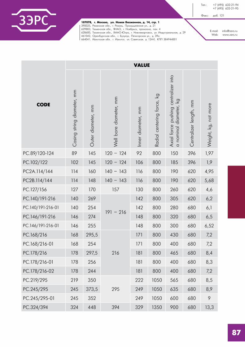
107078, �. l%“*"=, 3�. m%"= a=“�=……= , . 14, “2!. 1390025, p ƒ=…“*= %K�., . p ƒ=…�, o!%/���……= 3�., �. 21629803, Š��…“*= %K�., “m`n, . m% K!�“*, C!%ƒ%…=, C=…. 4628600, Š��…“*= %K�., ul`n-~ !=, . m,›…�"=!2%"“*, 3�. h…�3“2!,=��…= , �. 29461042, n!�…K3! “*= %K�., . a3ƒ3�3*, o 2, %!“*= 3�., �. 39=664041, h!*32“*= %K�., . h!*32“*, 3�. q%"�2“*= , �. 124-e, joo 384944001
E-mail: [email protected]: www.zers.ru
Š��.: +7 (495) 632-21-94 +7 (495) 632-21-95
t=*“: �%K. 121
CODE
VALUE
Casing
strin
g d
iam
eter
, m
m
Out
er d
iam
eter
, m
m
Wel
l bore
dia
met
er, m
m
Inne
r dia
met
er, m
m
Radia
l ce
nter
ing forc
e, k
g
Axial fo
rce
pus
hing
cen
traliz
er int
o
a n
om
inal dia
met
er, kg
Cen
traliz
er len
gth
, m
m
Wei
ght
, kg
, no
t m
ore
PC.89/120-124 89 145 120 – 124 92 800 150 396 1,97
PC.102/122 102 145 120 – 124 106 800 185 396 1,9
PC2А.114/144 114 160 140 – 143 116 800 190 620 4,95
PC2B.114/144 114 148 140 – 143 116 800 190 620 5,68
PC.127/156 127 170 157 130 800 260 620 4,6
PC.140/191-216 140 269
191 – 216
142 800 305 620 6,2
PC.140/191-216-01 140 254 142 800 280 680 6,1
PC.146/191-216 146 274 148 800 320 680 6,5
PC.146/191-216-01 146 255 148 800 300 680 6,52
PC.168/216 168 295,5
216
171 800 430 680 7,2
PC.168/216-01 168 254 171 800 400 680 7,2
PC.178/216 178 297,5 181 800 465 680 8,4
PC.178/216-01 178 256 181 800 400 680 8,3
PC.178/216-02 178 244 181 800 400 680 7,2
PC.219/295 219 350
295
222 1050 565 680 8,5
PC.245/295 245 373,5 249 1050 635 680 8,9
PC.245/295-01 245 352 249 1050 600 680 9
PC.324/394 324 448 394 329 1350 900 680 13,3
87
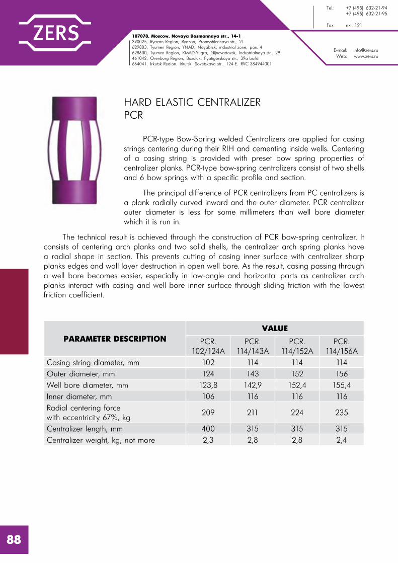
E-mail: [email protected]: www.zers.ru
Tel.: +7 (495) 632-21-94 +7 (495) 632-21-95
Fax: ext. 121
107078, Moscow, Novaya Basmannaya str., 14-1390025, Ryazan Region, Ryazan, Promyshlennaya str., 21629803, Tyumen Region, YNAD, Noyabrsk, industrial zone, pan. 4628600, Tyumen Region, KMAD-Yugra, Nijnevartovsk, Industrialnaya str., 29461042, Orenburg Region, Buzuluk, Pyatigorskaya str., 39a build664041, Irkutsk Region, Irkutsk, Sovetskaya str., 124-e, RVC 384944001
88
HARD ELASTIC CENTRALIZER PCR
PCR-type Bow-Spring welded Centralizers are applied for casing strings centering during their RIH and cementing inside wells. Centering of a casing string is provided with preset bow spring properties of centralizer planks. PCR-type bow-spring centralizers consist of two shells and 6 bow springs with a specific profile and section.
The principal difference of PCR centralizers from PC centralizers is a plank radially curved inward and the outer diameter. PCR centralizer outer diameter is less for some millimeters than well bore diameter which it is run in.
The technical result is achieved through the construction of PCR bow-spring centralizer. It consists of centering arch planks and two solid shells, the centralizer arch spring planks have a radial shape in section. This prevents cutting of casing inner surface with centralizer sharp planks edges and wall layer destruction in open well bore. As the result, casing passing through a well bore becomes easier, especially in low-angle and horizontal parts as centralizer arch planks interact with casing and well bore inner surface through sliding friction with the lowest friction coefficient.
PARAMETER DESCRIPTIONVALUE
PCR.102/124A
PCR.114/143A
PCR.114/152A
PCR.114/156A
Casing string diameter, mm 102 114 114 114
Outer diameter, mm 124 143 152 156
Well bore diameter, mm 123,8 142,9 152,4 155,4
Inner diameter, mm 106 116 116 116
Radial centering force with eccentricity 67%, kg
209 211 224 235
Centralizer length, mm 400 315 315 315
Centralizer weight, kg, not more 2,3 2,8 2,8 2,4

107078, �. l%“*"=, 3�. m%"= a=“�=……= , . 14, “2!. 1390025, p ƒ=…“*= %K�., . p ƒ=…�, o!%/���……= 3�., �. 21629803, Š��…“*= %K�., “m`n, . m% K!�“*, C!%ƒ%…=, C=…. 4628600, Š��…“*= %K�., ul`n-~ !=, . m,›…�"=!2%"“*, 3�. h…�3“2!,=��…= , �. 29461042, n!�…K3! “*= %K�., . a3ƒ3�3*, o 2, %!“*= 3�., �. 39=664041, h!*32“*= %K�., . h!*32“*, 3�. q%"�2“*= , �. 124-e, joo 384944001
E-mail: [email protected]: www.zers.ru
Š��.: +7 (495) 632-21-94 +7 (495) 632-21-95
t=*“: �%K. 121
LOW-FRICTIONAL TURBULENCE GENERATING CENTRALIZER CTN
Low-frictional Turbulence Generating Centralizer is applied for casing RIH and turbulence generation of cement slurry upward flow during cementing. Low-frictional centralizers application allows to improve casing passing through a bore, especially in horizontal wells and wells with significant vertical deviation.
CTN centralizers reduce the risk of tool sticking. They are mounted on a casing pipe movably and are protected from shifting with lockdown rings FK.
PARAMETER DESCRIPTION
VALUE
CTN
.102/
116
CTN
.102/
119
CTN
.114
/138
CTN
.114
/150
CTN
.127
/146
CTN
.168/
206
CTN
.178
/206
Liner nominal diameter equipped with the device, mm
102 102 114 114 127 168 178
Outer diameter, mm 116 119 138 150 146 206 206
Nominal open hole diameter (bit diameter) where the device is RIH, mm
123,8 123,8 142,9 155,6 155,6 215,9 215,9
Length, mm 185 185 220 220 220 250 250
Friction coefficient at dry friction 0,2
Friction coefficient at fluid friction less than 0,08
It can be produced according to Customer’s individual sizes.
89
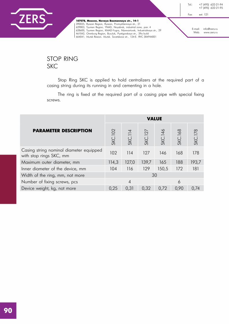
E-mail: [email protected]: www.zers.ru
Tel.: +7 (495) 632-21-94 +7 (495) 632-21-95
Fax: ext. 121
107078, Moscow, Novaya Basmannaya str., 14-1390025, Ryazan Region, Ryazan, Promyshlennaya str., 21629803, Tyumen Region, YNAD, Noyabrsk, industrial zone, pan. 4628600, Tyumen Region, KMAD-Yugra, Nijnevartovsk, Industrialnaya str., 29461042, Orenburg Region, Buzuluk, Pyatigorskaya str., 39a build664041, Irkutsk Region, Irkutsk, Sovetskaya str., 124-e, RVC 384944001
STOP RING SKC
Stop Ring SKC is applied to hold centralizers at the required part of a casing string during its running in and cementing in a hole.
The ring is fixed at the required part of a casing pipe with special fixing screws.
PARAMETER DESCRIPTION
VALUESK
C.102
SKC
.114
SKC
.127
SKC
.146
SKC
.168
SKC
.178
Casing string nominal diameter equipped with stop rings SKC, mm
102 114 127 146 168 178
Maximum outer diameter, mm 114,3 127,0 139,7 165 188 193,7
Inner diameter of the device, mm 104 116 129 150,5 172 181
Width of the ring, mm, not more 30
Number of fixing screws, pcs 4 6
Device weight, kg, not more 0,25 0,31 0,32 0,72 0,90 0,74
90

107078, �. l%“*"=, 3�. m%"= a=“�=……= , . 14, “2!. 1390025, p ƒ=…“*= %K�., . p ƒ=…�, o!%/���……= 3�., �. 21629803, Š��…“*= %K�., “m`n, . m% K!�“*, C!%ƒ%…=, C=…. 4628600, Š��…“*= %K�., ul`n-~ !=, . m,›…�"=!2%"“*, 3�. h…�3“2!,=��…= , �. 29461042, n!�…K3! “*= %K�., . a3ƒ3�3*, o 2, %!“*= 3�., �. 39=664041, h!*32“*= %K�., . h!*32“*, 3�. q%"�2“*= , �. 124-e, joo 384944001
E-mail: [email protected]: www.zers.ru
Š��.: +7 (495) 632-21-94 +7 (495) 632-21-95
t=*“: �%K. 121
CEMENTING THROTTLE CHECK VALVE CKOD
Cementing Throttle Check Valve is applied for prevention of cement slurry backflow during cementing and for self-priming of casing inner space during RIH.
Inner parts of the valve are made of easily drilled out materials.
PARAMETER DESCRIPTION VALUE
Casing string nominal diameter RIH with CKOD valve, mm
146 168 178 245 324
Maximum outer diameter, mm 166 187 194,5 270 348
Drift diameter, mm 130,7 152,3 161,6 226,7 304,9
Ball diameter, mm 76
Length in operating position, mm 430 432 436 429 442
Length in transport position, mm 420 430 440 440 450
Weight in operating position, kg 19, 5 22,1 24,5 55,1 95,9
Weight in transport position, kg 20,4 23,2 25,7 56,4 98,3
Maximum operating temperature1, °C 100
Maximum tensile force on the device body1, kN (tn)
900(90)
920(92)
1050(105)
1700(170)
1900(190)
Maximum internal overpressure on the valve body, MPa
25
Maximum differential pressure maintained by the valve, MPa
15
Connecting threads3:- top and bottom according to GOST 632-80
ОТТМ146
ОТТМ168
ОТТМ178
ОТТМ245
ОТТМ324
1 Reference only, depends on operating conditions of general mechanical rubber goods in a well.2 Calculated value when stresses reach yield point of the material.3 OTTG or BTS connecting threads can be produced on Customer’s demand. 91

E-mail: [email protected]: www.zers.ru
Tel.: +7 (495) 632-21-94 +7 (495) 632-21-95
Fax: ext. 121
107078, Moscow, Novaya Basmannaya str., 14-1390025, Ryazan Region, Ryazan, Promyshlennaya str., 21629803, Tyumen Region, YNAD, Noyabrsk, industrial zone, pan. 4628600, Tyumen Region, KMAD-Yugra, Nijnevartovsk, Industrialnaya str., 29461042, Orenburg Region, Buzuluk, Pyatigorskaya str., 39a build664041, Irkutsk Region, Irkutsk, Sovetskaya str., 124-e, RVC 384944001
CASING SHOE BK
BK is a casing shoe applied for directing a casing string during its running in the well bore.
There are 4 options of design:
1). BK-M are shoes with metal cap (if the customer approves, a cap is made of aluminium alloy according to D16T GOST 4784-97 or of cast iron mark Sch20 GOST 1412-85, default variant is aluminium);
2). BK-M are shoes with metal cap “bullet-shaped” (a cap is made of aluminium alloy according to D16T GOST 4784-97);
3). BK-P are shoes with polymer cap. BK-P shoes can also be produced without wash ports (“blind”). Index “G” is added to such models.
4). BK-Vr are rotating shoes with rotating eccentric cap (a cap is made of aluminium alloy according to D16T GOST 4784-97).
CODE
VALUE
Casing
strin
g
nom
inal
dia
met
er, m
m
Cen
tral ho
le
dia
met
er, m
m
Sid
e ho
les
dia
met
er, m
m
Drift d
iam
eter
, m
m
Conn
ectin
g
thre
ads1,
acc
ord
ing to
GO
ST 6
32-
80
Out
er
dia
met
er, m
m,
not m
ore
Leng
th, m
m
Wei
ght
, kg
,
not m
ore
BK-P 89 89 40 10 80 89 108 262 7,4
BK-P 102 102 40 12 91 OTTM 102 110 260 5,7
BK-P 114 114 50 12 102 OTTM 114 127 287 8,1
BK-P 127 127 60 12 115 OTTM 127 141,3 285 9,9
BK-P 140 140 70 15 127 OTTM 140 153,7 294 15,4
BK-P 146 146 70 15 133 OTTM 146 166 302 15,5
BK-P 168 168 80 15 155 OTTM 168 187,7 316 18,6
BK-P 178 178 90 18 164 OTTM 178 194,5 341 19,6
BK-P 194 194 100 20 178 OTTM 194 216 365 28,1
BK-P 219 219 110 20 205 OTTM 219 245 370 35,8
BK-P 245 245 120 20 228 OTTM 245 270 390 43,1
BK-P 273 273 130 20 259 OTTM 273 298,5 384 56,6
BK-P 299 299 150 20 281 OTTM 299 324 389 63,4
BK-P 324 324 160 20 307 OTTM 324 351 400 62,6
BK-P 340 340 170 20 323 OTTM 340 365 405 63,6
BK-P 426 426 220 20 406 OTTM 426 451 433 123,5
1 Connecting thread type is agreed with the Customer. For BK-P 89, BK-P 89G the thread is produced according to GOST 633-80; for the shoe BK-P 102, BK-P 102G, BK-M 102 the thread is produced according to TU 14-161-163-96.
SHOES WITH POLYMER-CONCRETE CAP
92

107078, �. l%“*"=, 3�. m%"= a=“�=……= , . 14, “2!. 1390025, p ƒ=…“*= %K�., . p ƒ=…�, o!%/���……= 3�., �. 21629803, Š��…“*= %K�., “m`n, . m% K!�“*, C!%ƒ%…=, C=…. 4628600, Š��…“*= %K�., ul`n-~ !=, . m,›…�"=!2%"“*, 3�. h…�3“2!,=��…= , �. 29461042, n!�…K3! “*= %K�., . a3ƒ3�3*, o 2, %!“*= 3�., �. 39=664041, h!*32“*= %K�., . h!*32“*, 3�. q%"�2“*= , �. 124-e, joo 384944001
E-mail: [email protected]: www.zers.ru
Š��.: +7 (495) 632-21-94 +7 (495) 632-21-95
t=*“: �%K. 121
SHOES WITH METAL CAP
CODE
VALUEC
asing
strin
g
nom
inal
dia
met
er, m
m
Cen
tral ho
le
dia
met
er, m
m
Sid
e ho
les
dia
met
er, m
m
Drift d
iam
eter
, m
m
Conn
ectin
g
thre
ads1,
acc
ord
ing to
GO
ST 6
32-
80
Out
er
dia
met
er, m
m,
not m
ore
Leng
th, m
m
Wei
ght
, kg
,
not m
ore
BK-M 89 89 45 10 82 89 108 198 5,2
BK-M 102 102 50 12 94 OTTM 102 110 218 4
BK-M 114 114 55 15 107 OTTM 114 127 259 7,1
BK-M 127 127 60 15 119 OTTM 127 141,3 269 8,2
BK-M 140 140 70 15 132 OTTM 140 153,7 263 9,7
BK-M 146 146 70 15 138 OTTM 146 166 268 12,5
BK-M 168 168 80 15 160 OTTM 168 187,7 282 15,9
BK-M 178 178 90 20 170 OTTM 178 194,5 293 16,5
BK-M 194 194 100 20 185 OTTM 194 216 308 22,9
BK-M 219 219 110 20 210 OTTM 219 245 328 31,4
BK-M 245 245 120 20 236 OTTM 245 270 341 36,8
BK-M 273 273 130 20 264 OTTM 273 298,5 350 43,6
BK-M 299 299 150 20 290 OTTM 299 324 352 47,8
BK-M 324 324 160 20 315 OTTM 324 351 359 56,4
BK-M 340 340 170 20 331 OTTM 340 365 364 58,4
BK-M 426 426 220 20 415 OTTM 426 451 406 89,7
1 Connecting thread type is agreed with the Customer. For BK-M 89, BK-M 89G the thread is produced according to GOST 633-80; for the shoe BK-M 102, BK-M 102G the thread is produced according to TU 14-161-163-96; for the shoe BK-M 426 the thread is produced according to TU 14-3-760-78.
93
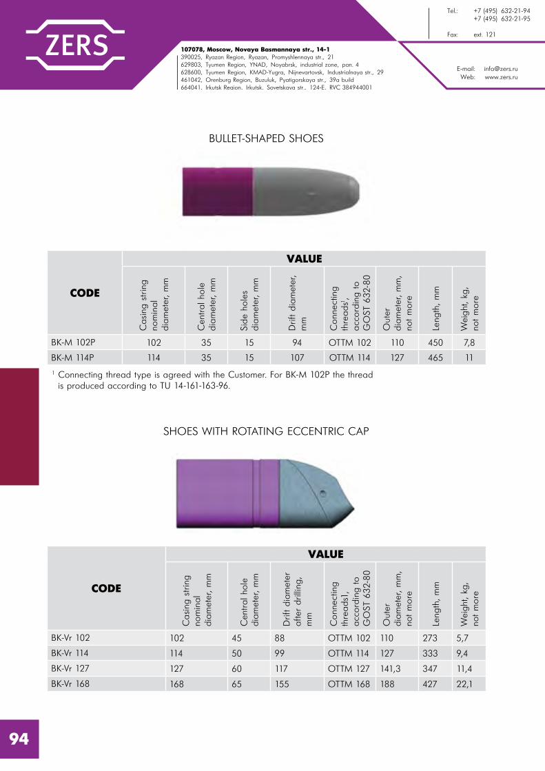
E-mail: [email protected]: www.zers.ru
Tel.: +7 (495) 632-21-94 +7 (495) 632-21-95
Fax: ext. 121
107078, Moscow, Novaya Basmannaya str., 14-1390025, Ryazan Region, Ryazan, Promyshlennaya str., 21629803, Tyumen Region, YNAD, Noyabrsk, industrial zone, pan. 4628600, Tyumen Region, KMAD-Yugra, Nijnevartovsk, Industrialnaya str., 29461042, Orenburg Region, Buzuluk, Pyatigorskaya str., 39a build664041, Irkutsk Region, Irkutsk, Sovetskaya str., 124-e, RVC 384944001
BULLET-SHAPED SHOES
SHOES WITH ROTATING ECCENTRIC CAP
CODE
VALUE
Casing
strin
g
nom
inal
dia
met
er, m
m
Cen
tral ho
le
dia
met
er, m
m
Sid
e ho
les
dia
met
er, m
m
Drift d
iam
eter
, m
m
Conn
ectin
g
thre
ads1,
acc
ord
ing to
GO
ST 6
32-
80
Out
er
dia
met
er, m
m,
not m
ore
Leng
th, m
m
Wei
ght
, kg
,
not m
ore
BK-M 102P 102 35 15 94 ОТТМ 102 110 450 7,8
BK-M 114P 114 35 15 107 ОТТМ 114 127 465 11
1 Connecting thread type is agreed with the Customer. For BK-M 102P the thread is produced according to TU 14-161-163-96.
CODE
VALUE
Casing
strin
g
nom
inal
dia
met
er, m
m
Cen
tral ho
le
dia
met
er, m
m
Drift d
iam
eter
after
drilling
, m
m
Conn
ectin
g
thre
ads1
, acc
ord
ing to
GO
ST 6
32-
80
Out
er
dia
met
er, m
m,
not m
ore
Leng
th, m
m
Wei
ght
, kg
,
not m
ore
BK-Vr 102 102 45 88 OTTM 102 110 273 5,7
BK-Vr 114 114 50 99 OTTM 114 127 333 9,4
BK-Vr 127 127 60 117 OTTM 127 141,3 347 11,4
BK-Vr 168 168 65 155 OTTM 168 188 427 22,1
94
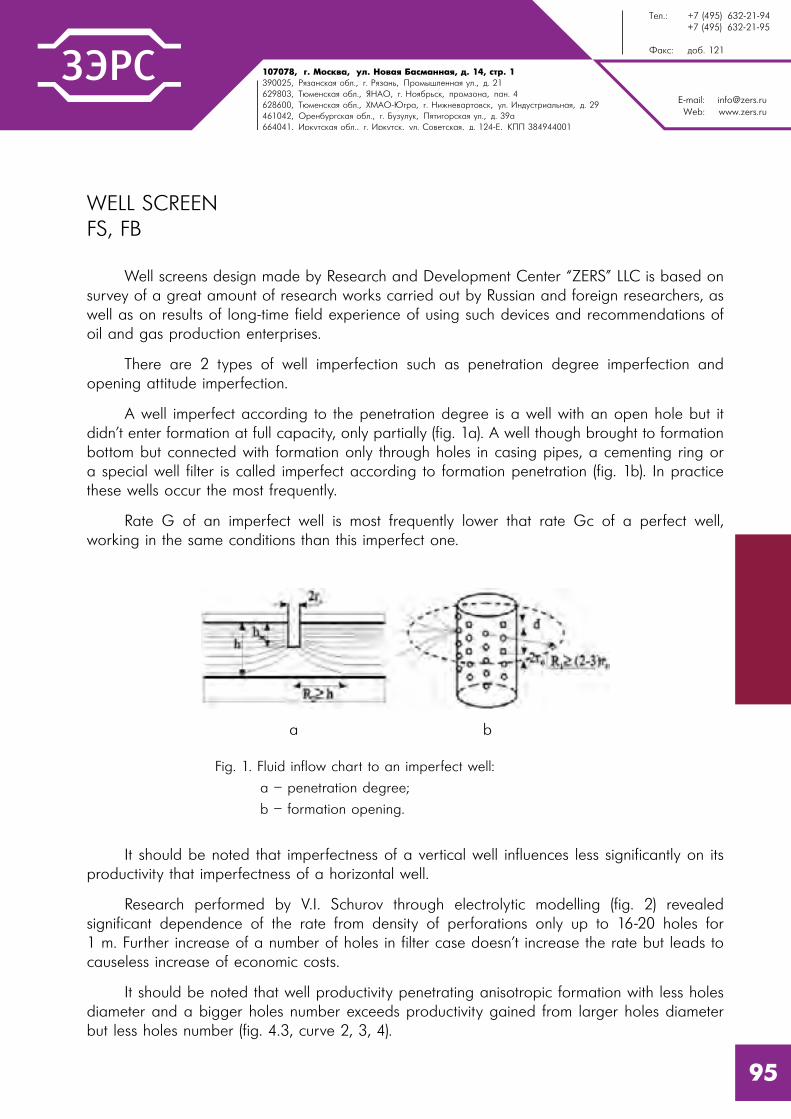
107078, �. l%“*"=, 3�. m%"= a=“�=……= , . 14, “2!. 1390025, p ƒ=…“*= %K�., . p ƒ=…�, o!%/���……= 3�., �. 21629803, Š��…“*= %K�., “m`n, . m% K!�“*, C!%ƒ%…=, C=…. 4628600, Š��…“*= %K�., ul`n-~ !=, . m,›…�"=!2%"“*, 3�. h…�3“2!,=��…= , �. 29461042, n!�…K3! “*= %K�., . a3ƒ3�3*, o 2, %!“*= 3�., �. 39=664041, h!*32“*= %K�., . h!*32“*, 3�. q%"�2“*= , �. 124-e, joo 384944001
E-mail: [email protected]: www.zers.ru
Š��.: +7 (495) 632-21-94 +7 (495) 632-21-95
t=*“: �%K. 121
WELL SCREEN FS, FB
Well screens design made by Research and Development Center “ZERS” LLC is based on survey of a great amount of research works carried out by Russian and foreign researchers, as well as on results of long-time field experience of using such devices and recommendations of oil and gas production enterprises.
There are 2 types of well imperfection such as penetration degree imperfection and opening attitude imperfection.
A well imperfect according to the penetration degree is a well with an open hole but it didn’t enter formation at full capacity, only partially (fig. 1a). A well though brought to formation bottom but connected with formation only through holes in casing pipes, a cementing ring or a special well filter is called imperfect according to formation penetration (fig. 1b). In practice these wells occur the most frequently.
Rate G of an imperfect well is most frequently lower that rate Gc of a perfect well, working in the same conditions than this imperfect one.
It should be noted that imperfectness of a vertical well influences less significantly on its productivity that imperfectness of a horizontal well.
Research performed by V.I. Schurov through electrolytic modelling (fig. 2) revealed significant dependence of the rate from density of perforations only up to 16-20 holes for 1 m. Further increase of a number of holes in filter case doesn’t increase the rate but leads to causeless increase of economic costs.
It should be noted that well productivity penetrating anisotropic formation with less holes diameter and a bigger holes number exceeds productivity gained from larger holes diameter but less holes number (fig. 4.3, curve 2, 3, 4).
Fig. 1. Fluid inflow chart to an imperfect well:
a – penetration degree;
b – formation opening.
a b
95

E-mail: [email protected]: www.zers.ru
Tel.: +7 (495) 632-21-94 +7 (495) 632-21-95
Fax: ext. 121
107078, Moscow, Novaya Basmannaya str., 14-1390025, Ryazan Region, Ryazan, Promyshlennaya str., 21629803, Tyumen Region, YNAD, Noyabrsk, industrial zone, pan. 4628600, Tyumen Region, KMAD-Yugra, Nijnevartovsk, Industrialnaya str., 29461042, Orenburg Region, Buzuluk, Pyatigorskaya str., 39a build664041, Irkutsk Region, Irkutsk, Sovetskaya str., 124-e, RVC 384944001
Without further reasons and calculations we should notice that LLC RDC “ZERS” considers the most efficient well filter design including 28 holes with diameter 10 mm per 1 m.
FS-type well filter is applied as a part of a casing string filtering part and is used to prevent destruction of productive formation bottom-hole area and sand or other mechanical impurities intrusion. The filter is run into productive formation and installed in a required interval of the well with the help of a liner hanger or as a part of a casing string. FS-type filter is a device consisting of a case with holes on the outer side of which there is a slit-type filter element manufactured by spiral winding of stainless steel wire with a special triangular section onto longitudinal load-bearing elements (stringers). The length of the filter element, the gap size and a number of holes in the body as per 1 linear meter of its length are defined by its intended operational conditions and are subject to approval with the customer.
FS filter is available in variants with hollow plugs “caps” (variant K) and without them. The plugs are installed in the holes of the case and provide filter leak tightness up to 15 MPa of internal overpressure. It thus allows to washover a well through a casing shoe. The hollow plugs are removed by mechanical destruction.
Fig. 4.3 Q dependence of f perforation porosity
1 – anisotropic formation (d=6.3*10-3m);
2 – isotropic formation (d=6.3*10-3m);
3 – isotropic formation (d=2*10-3m);
4 – isotropic formation (d=0.5*10-3m);
d – perforation holes diameter; f=fh/F; fh – holes surface for 1 lin. m of perforated surface F
Fig. 4.4 Q dependence of the number of holes n
1 – a=0.3, b=0.1;
2 – a=10, b=0.001
96

107078, �. l%“*"=, 3�. m%"= a=“�=……= , . 14, “2!. 1390025, p ƒ=…“*= %K�., . p ƒ=…�, o!%/���……= 3�., �. 21629803, Š��…“*= %K�., “m`n, . m% K!�“*, C!%ƒ%…=, C=…. 4628600, Š��…“*= %K�., ul`n-~ !=, . m,›…�"=!2%"“*, 3�. h…�3“2!,=��…= , �. 29461042, n!�…K3! “*= %K�., . a3ƒ3�3*, o 2, %!“*= 3�., �. 39=664041, h!*32“*= %K�., . h!*32“*, 3�. q%"�2“*= , �. 124-e, joo 384944001
E-mail: [email protected]: www.zers.ru
Š��.: +7 (495) 632-21-94 +7 (495) 632-21-95
t=*“: �%K. 121
1 – Shaped wire.
2 – Stringer.
3 – Gap width (clearance).
1 2
3
97

E-mail: [email protected]: www.zers.ru
Tel.: +7 (495) 632-21-94 +7 (495) 632-21-95
Fax: ext. 121
107078, Moscow, Novaya Basmannaya str., 14-1390025, Ryazan Region, Ryazan, Promyshlennaya str., 21629803, Tyumen Region, YNAD, Noyabrsk, industrial zone, pan. 4628600, Tyumen Region, KMAD-Yugra, Nijnevartovsk, Industrialnaya str., 29461042, Orenburg Region, Buzuluk, Pyatigorskaya str., 39a build664041, Irkutsk Region, Irkutsk, Sovetskaya str., 124-e, RVC 384944001
FB-type wireless filter differs from FS filter by lack of filter element on the case outer surface. It is also available with hollow plugs “caps” and in plug-less variants. Maximum test pressure of a filter for the variant with hollow plugs is 15 MPa.
Here is an example of identification symbols to order a well screen with hollow plugs for a casing string with diameter 114 mm with slit clearance size of 0,25 mm and filter element length of 3000 mm provided with a positive centralizer with diameter of 136 mm:
FS 114 – 3000 – 0,25 – 10х28 – C 136 – K
FB 102 – 12х28 – K
Well filter
Casing string nominal diameter – 114 mm
Filtering element length – 3000 mm
Filter element gap – 0,25 mm
Radial hole diameter and number of holes on 1 lin. m
Positive centralizer presence
Positive centralizer diameter
Model with hollow plugs
Wireless well filter
Casing string nominal diameter – 102 mm
Radial hole diameter and number of holes on 1 lin. m
Model with hollow plugs
Here is an example of identification symbols to order a wireless filter with hollow plugs with holes diameter 12 mm for a casing string with diameter 102 mm:
98

107078, �. l%“*"=, 3�. m%"= a=“�=……= , . 14, “2!. 1390025, p ƒ=…“*= %K�., . p ƒ=…�, o!%/���……= 3�., �. 21629803, Š��…“*= %K�., “m`n, . m% K!�“*, C!%ƒ%…=, C=…. 4628600, Š��…“*= %K�., ul`n-~ !=, . m,›…�"=!2%"“*, 3�. h…�3“2!,=��…= , �. 29461042, n!�…K3! “*= %K�., . a3ƒ3�3*, o 2, %!“*= 3�., �. 39=664041, h!*32“*= %K�., . h!*32“*, 3�. q%"�2“*= , �. 124-e, joo 384944001
E-mail: [email protected]: www.zers.ru
Š��.: +7 (495) 632-21-94 +7 (495) 632-21-95
t=*“: �%K. 121
The figure shows an FS-type filter designed with hollow plugs.
PARAMETER DESCRIPTION VALUE
Casing string diameter, D1, mm 48 60 73 89 102 114 127
Maximum filter element diameter, D2, mm
65 78 90 107 116 129 148
Radial holes diameter in model with hollow plugs, D3, mm
10
Radial holes diameter in model without hollow plugs, D3*, mm
12; 15
Filter drift diameter, D4, mm 40,3 50,3 62,0 75,9 88,6 101,5 114,2
Outer diameter according to positive centralizer, D5*, mm
– – 100 116 125 136 150
Filter length, K*, mm 4588…11088 4600…11100
Filter element length, F*, mm 3000 or 6000
Top part length of filter body, V, mm not less than 1200
Bottom part length of filter body, N, mm
no less than 300
Filter element gap, A±0,05*, mm 0,15; 0,20; 0,25; 0,30; 0,35; 0,40; 0,50; 0,60; 0,70; 0,85; 1,00
* Other sizes are available on Customer’s demand.
99

E-mail: [email protected]: www.zers.ru
Tel.: +7 (495) 632-21-94 +7 (495) 632-21-95
Fax: ext. 121
107078, Moscow, Novaya Basmannaya str., 14-1390025, Ryazan Region, Ryazan, Promyshlennaya str., 21629803, Tyumen Region, YNAD, Noyabrsk, industrial zone, pan. 4628600, Tyumen Region, KMAD-Yugra, Nijnevartovsk, Industrialnaya str., 29461042, Orenburg Region, Buzuluk, Pyatigorskaya str., 39a build664041, Irkutsk Region, Irkutsk, Sovetskaya str., 124-e, RVC 384944001
PARAMETER DESCRIPTION VALUE
Casing string diameter, D1, mm 140 146 168 178 194 219 245
Maximum filter element diameter, D2, mm
159 166 188 198 213 238 264
Radial holes diameter in model with hollow plugs, D3, mm
10
Radial holes diameter in model without hollow plugs, D3*, mm
12; 15
Filter drift diameter, D4, mm 127,3 133,1 153,7 164,0 178,5 205,7 228,7
Outer diameter according to positive centralizer, D5, mm
162 174 195 206 224 258 285
Filter length, K*, mm 4616…11134
Filter element length, F*, mm 3000 or 6000
Top part length of filter body, V, mm not less than 1200
Bottom part length of filter body, N, mm
no less than 300
Filter element gap, A±0,05*, mm 0,15; 0,20; 0,25; 0,30; 0,35; 0,40; 0,50; 0,60; 0,70; 0,85; 1,00
* Other sizes are available on Customer’s demand.
The figure shows an FB-type filter designed with hollow plugs.
100


IV
102Selective Washing Device for Wells USPS . . . . . . . . . . . . . . . . . . . . . . .
DRILLING EQUIPMENT
E-mail: [email protected]: www.zers.ru
Tel.: +7 (495) 632-21-94 +7 (495) 632-21-95
Fax: ext. 121
107078, Moscow, Novaya Basmannaya str., 14-1390025, Ryazan Region, Ryazan, Promyshlennaya str., 21629803, Tyumen Region, YNAD, Noyabrsk, industrial zone, pan. 4628600, Tyumen Region, KMAD-Yugra, Nijnevartovsk, Industrialnaya str., 29461042, Orenburg Region, Buzuluk, Pyatigorskaya str., 39a build664041, Irkutsk Region, Irkutsk, Sovetskaya str., 124-e, RVC 384944001
SELECTIVE WASHING DEVICE FOR WELLS USPS
Selective Washing Device for Wells is applied for performing injections of plugs with fillers during drilling with bottomhole engine. The device is mounted above BHA.
When the device is not actuated, drilling mud goes through it smoothly. To activate the device it is necessary to drop an activation ball into drilling pipes and pump until it is set into a seat. When the activation ball reaches the seat, circulating ports open. Due to this BHA is hermetically disconnected as it is mounted lower. The circulation goes through the side ports and the bridging material is pumped into loss zones. When a drilling pump is stopped, a spring returns the stem to the top position and circulation ports are closed.
After all the planned technical operations two steel deactivation balls are dropped into drilling pipes and pumped with calculated volume of drilling mud in order to deactivate the device. Deactivation balls reach the device and close the ports due to liquid flow and the deactivation ball is pumped through a seat. The circulating ports are closed. Drilling mud continues to flow below the device. Used balls both activation and deactivation one come to a trap and don’t interfere with the following operations.
104

107078, �. l%“*"=, 3�. m%"= a=“�=……= , . 14, “2!. 1390025, p ƒ=…“*= %K�., . p ƒ=…�, o!%/���……= 3�., �. 21629803, Š��…“*= %K�., “m`n, . m% K!�“*, C!%ƒ%…=, C=…. 4628600, Š��…“*= %K�., ul`n-~ !=, . m,›…�"=!2%"“*, 3�. h…�3“2!,=��…= , �. 29461042, n!�…K3! “*= %K�., . a3ƒ3�3*, o 2, %!“*= 3�., �. 39=664041, h!*32“*= %K�., . h!*32“*, 3�. q%"�2“*= , �. 124-e, joo 384944001
E-mail: [email protected]: www.zers.ru
Š��.: +7 (495) 632-21-94 +7 (495) 632-21-95
t=*“: �%K. 121
105
PARAMETER DESCRIPTION
VALUE
USPS.121 USPS.171
Outer diameter of the device, mm 121 171
Diameter of circulating ports, mm 28 28
Number of circulating ports, pcs 2 2
Number of operation cycles, without pulling out, units 5 5
Activation ball diameter, mm 38,1 50,8
Deactivation ball diameter, mm 34,9 34,9
Length, mm 1688 1841
Weight, kg 113 260
Connecting threads according to GOST 632-80 (for SPD2.102 according to TU 14-161-163-96)
Z-102 Z-133
Maximum tensile force1, kN (tn) 1962 (200) 4905 (500)1 Calculated value.


V
106108109111112114
115
117
118
Technical Equipment Set for a Liner Well Casing with the following Multistage Hydraulic Fracturing . . . . . . . . . . . . . . . . .
Check Valve KO . . . . . . . . . . . . . . . . . . . . . . . . . . . . . . . . . . . . . . . . .
Hydraulic Packer for Hydraulic Fracturing PGRP . . . . . . . . . . . . . . . . . .
Water and Oil Swellable Packer for Hydraulic Fracturing . . . . . . . . . . . .
Staged Hydraulic Fracturing Collar MSGRP and MSGRP-G . . . . . . . . . .
Closing Frac Port FPZ and FPZ-G
Collar for Collar Cementing Sleeve for Hydraulic Fracturing MMC-G . . . . . . . . . . . . . . . . . . . . . . . . . . . . .
Set of Equipment for Multistage Hydraulic Fracturing with Unlimited Number of Ports and Possibility of the Second Hydraulic Fracturing or Opening/Closing of Ports . . . . . . . . . . . . . . . . . . . . . . . . . . . . . . . .
Collar for Staged Hydraulic Fracturing with an Operating Device MSGRP-U . . . . . . . . . . . . . . . . . . . . . . . . . .
HYDRAULIC FRACTURING
E-mail: [email protected]: www.zers.ru
Tel.: +7 (495) 632-21-94 +7 (495) 632-21-95
Fax: ext. 121
107078, Moscow, Novaya Basmannaya str., 14-1390025, Ryazan Region, Ryazan, Promyshlennaya str., 21629803, Tyumen Region, YNAD, Noyabrsk, industrial zone, pan. 4628600, Tyumen Region, KMAD-Yugra, Nijnevartovsk, Industrialnaya str., 29461042, Orenburg Region, Buzuluk, Pyatigorskaya str., 39a build664041, Irkutsk Region, Irkutsk, Sovetskaya str., 124-e, RVC 384944001
TECHNICAL EQUIPMENT SET FOR A LINER WELL CASING WITH THE FOLLOWING MULTISTAGE HYDRAULIC FRACTURING
Technical equipment sets for multistage hydraulic fracturing vary in a liner well casing type:
- without cementing;
- with collar cementing;
- with continuous cementing.
There are also different types of horizontal sector zonal isolation:
- with the help of swellable packers;
- with the help of hydro-mechanical packers.
A set for well casing with a liner without cementing with the following multistage hydraulic fracturing includes the following technical equipment:
1. Shoe;
2. Ball check valve KOSH2;
3. Check valve KO;
4. Hydraulically opening collar MSGRP-G;
5. Required amount of packers (swellable or hydro-mechanical) and collars MSGRP which are opened with balls;
6. Noncemented liner hanger PHN.
108

107078, �. l%“*"=, 3�. m%"= a=“�=……= , . 14, “2!. 1390025, p ƒ=…“*= %K�., . p ƒ=…�, o!%/���……= 3�., �. 21629803, Š��…“*= %K�., “m`n, . m% K!�“*, C!%ƒ%…=, C=…. 4628600, Š��…“*= %K�., ul`n-~ !=, . m,›…�"=!2%"“*, 3�. h…�3“2!,=��…= , �. 29461042, n!�…K3! “*= %K�., . a3ƒ3�3*, o 2, %!“*= 3�., �. 39=664041, h!*32“*= %K�., . h!*32“*, 3�. q%"�2“*= , �. 124-e, joo 384944001
E-mail: [email protected]: www.zers.ru
Š��.: +7 (495) 632-21-94 +7 (495) 632-21-95
t=*“: �%K. 121
109
A set for well casing with a liner with cementing with the following multistage hydraulic fracturing includes the following technical equipment:
1. Shoe;
2. Ball check valve KOSH2;
3. Check valve KO;
4. Hydraulically opening collar MSGRP-G;
5. Required amount of packers (swellable or hydro-mechanical) and collars MSGRP which are opened with balls;
6. Seat-trap SL;
7. Collar cementing packer PGMC or collar for collar cementing for hydraulic fracturing MMC-G;
8. Cemented liner hanger PHCZ or PHGMC.
After well casing with a liner and normalization are finished, the connection with a liner is performed with a hydraulic fracturing device UGRH, wellhead set-up and frac fitting are mounted.
Actually multistage hydraulic fracturing is performed with collars MSGRP which are actuated one by one at the right time. Collars are opened with internal overpressure build-up in a pass by pumping pressing balls if different diameter beginning with the smallest one and their setting to seats with different drift diameter. MSGRP-G hydraulically opening collar is used for the first interval hydraulic fracturing. Zonal isolation in outer annular space is performed with hydro-mechanical and swellable packers included into assembly RIH.
Equipment sets are delivered for liners 102 and 114 mm and can be used for up to 10 intervals of hydraulic fracturing at operational pressure up to 70 MPa.

E-mail: [email protected]: www.zers.ru
Tel.: +7 (495) 632-21-94 +7 (495) 632-21-95
Fax: ext. 121
107078, Moscow, Novaya Basmannaya str., 14-1390025, Ryazan Region, Ryazan, Promyshlennaya str., 21629803, Tyumen Region, YNAD, Noyabrsk, industrial zone, pan. 4628600, Tyumen Region, KMAD-Yugra, Nijnevartovsk, Industrialnaya str., 29461042, Orenburg Region, Buzuluk, Pyatigorskaya str., 39a build664041, Irkutsk Region, Irkutsk, Sovetskaya str., 124-e, RVC 384944001
110
CHECK VALVE KO
Check Valve KO is installed in a liner assembly for multistage hydraulic fracturing and applied for reliable disconnection of tube space and outer annular space.
The valve is actuated after liner RIH with ball-drop and pumping.
PARAMETER DESCRIPTION
VALUE
KO 102 KO 114
Liner nominal diameter equipped with the device, mm 102 114
Device maximum outer diameter, mm 114 127
Device drift diameter (after drilling), mm 89 99
Maximum pressure differential on the case, MPa 70 70
Maximum pressure differential hold by the valve, MPa 45 45
Length, mm 240 240
Weight, kg 19,2 24,7
Maximum operating temperature1, °C 100 100
Connecting threads according to GOST 632-80 (for KO 102 according to TU 14-161-163-96) OTTM-102 OTTM-1141 Reference only, depends on operating conditions of general mechanical rubber goods in a well.

107078, �. l%“*"=, 3�. m%"= a=“�=……= , . 14, “2!. 1390025, p ƒ=…“*= %K�., . p ƒ=…�, o!%/���……= 3�., �. 21629803, Š��…“*= %K�., “m`n, . m% K!�“*, C!%ƒ%…=, C=…. 4628600, Š��…“*= %K�., ul`n-~ !=, . m,›…�"=!2%"“*, 3�. h…�3“2!,=��…= , �. 29461042, n!�…K3! “*= %K�., . a3ƒ3�3*, o 2, %!“*= 3�., �. 39=664041, h!*32“*= %K�., . h!*32“*, 3�. q%"�2“*= , �. 124-e, joo 384944001
E-mail: [email protected]: www.zers.ru
Š��.: +7 (495) 632-21-94 +7 (495) 632-21-95
t=*“: �%K. 121
HYDRAULIC PACKER FOR HYDRAULIC FRACTURING PGRP
Hydraulic Packer PGRP is applied for open wellbore (or casing string) zonal isolation during different technological operations performance, including multistage hydraulic fracturing (MSHF).
The packer operates as follows:
- after liner running into the adjusted depth and flushing, a controlling ball is dropped till its setting into a valve KO seat, after which the pressure starts to increase.
- for packer hydraulic drive unit actuation the overpressure 16 (33) MPa is created in liner pipes. When the adjusted pressure is achieved, shear bolts are cut off and the packer is actuated.
For packer operation at significant pressures it is recommended to install the packer in intervals with open bore nominal diameter.
111

E-mail: [email protected]: www.zers.ru
Tel.: +7 (495) 632-21-94 +7 (495) 632-21-95
Fax: ext. 121
107078, Moscow, Novaya Basmannaya str., 14-1390025, Ryazan Region, Ryazan, Promyshlennaya str., 21629803, Tyumen Region, YNAD, Noyabrsk, industrial zone, pan. 4628600, Tyumen Region, KMAD-Yugra, Nijnevartovsk, Industrialnaya str., 29461042, Orenburg Region, Buzuluk, Pyatigorskaya str., 39a build664041, Irkutsk Region, Irkutsk, Sovetskaya str., 124-e, RVC 384944001
PARAMETER DESCRIPTION
VALUE
PGRP
.102/
118
PGRP
.102/
136
PGRP
.114
/136
PGRP
.114
/144
PGRP
.114
/148
Liner nominal diameter equipped with the device, mm
102 102 114 114 114
Open borehole nominal diameter (bit diameter) which the device is run in, mm
123,8 142,9 142,9 152,4 155,6
Outer diameter, mm 118 136 136 144 148
Drift diameter, after actuation, mm 88 88 99 99 98
Maximum tensile axial force on the body1, kN
600 600 700 700 700
Internal overpressure for packer actuation, MPa
16
Maximum pressure differential between the zones isolated by the packer, MPa
70
Maximum internal overpressure on the packer, MPa
70
Maximum operating temperature2, °C 100
Length, mm 1460 1295 1610 1700 1700
Weight, kg 51 56 65 78 80
Connecting threads:- top and bottom according to GOST 632-80 (for PGRP.102/118 and PGRP 102/136 according to TU 14-161-163-96)
OTTM-102
OTTM-102
OTTM-114
OTTM-114
OTTM-114
1 Calculated value.2 Reference only, depends on operating conditions of general mechanical rubber goods in a well.
112

107078, �. l%“*"=, 3�. m%"= a=“�=……= , . 14, “2!. 1390025, p ƒ=…“*= %K�., . p ƒ=…�, o!%/���……= 3�., �. 21629803, Š��…“*= %K�., “m`n, . m% K!�“*, C!%ƒ%…=, C=…. 4628600, Š��…“*= %K�., ul`n-~ !=, . m,›…�"=!2%"“*, 3�. h…�3“2!,=��…= , �. 29461042, n!�…K3! “*= %K�., . a3ƒ3�3*, o 2, %!“*= 3�., �. 39=664041, h!*32“*= %K�., . h!*32“*, 3�. q%"�2“*= , �. 124-e, joo 384944001
E-mail: [email protected]: www.zers.ru
Š��.: +7 (495) 632-21-94 +7 (495) 632-21-95
t=*“: �%K. 121
WATER AND OIL SWELLABLE PACKER FOR HYDRAULIC FRACTURING
RDC “ZERS” LLC has developed and produced oil swellable packers in which the sealing element is made of elastomeric material that is able to swell out at the contact with oil and can hold the pressure differential of 700 atm in a nominal diameter bore.
Besides, these packers’ body is made of steel with improved strength properties.
113
PARAMETER DESCRIPTION
PNV AND PNN PACKER TYPICAL SIZE
102/
118
102/
124
114/
136
114/
144
114/
148
127/
148
Liner nominal diameter on which the packer is RIH, mm
102 102 114 114 114 127
Recommended wellbore diameter which the packer is installed in, mm
124...
128132
143…
146
152…
156
156…
160
156…
160
Maximum pressure differential on the packer, MPa
70
Elastomeric material length, mm 1200
Packer length, mm 2600
Packer outer diameter, mm 118 124 136 144 148 148
Weight, kg 58 61 72 75 78 81
Maximum operating temperature, °C
100
Estimated packer swelling time till overall wellbore space isolation1, days
5…7 7…9
1 Parameters values are shown for the rated hole diameter on the base of used swelling resins types and well conditions (temperature, well fluid type on running in and operation, etc.).

E-mail: [email protected]: www.zers.ru
Tel.: +7 (495) 632-21-94 +7 (495) 632-21-95
Fax: ext. 121
107078, Moscow, Novaya Basmannaya str., 14-1390025, Ryazan Region, Ryazan, Promyshlennaya str., 21629803, Tyumen Region, YNAD, Noyabrsk, industrial zone, pan. 4628600, Tyumen Region, KMAD-Yugra, Nijnevartovsk, Industrialnaya str., 29461042, Orenburg Region, Buzuluk, Pyatigorskaya str., 39a build664041, Irkutsk Region, Irkutsk, Sovetskaya str., 124-e, RVC 384944001
STAGED HYDRAULIC FRACTURING COLLAR MSGRP AND MSGRP-G
Staged Hydraulic Fracturing Collar MSGRP is applied for multistage hydraulic fracturing.
A set of collars is RIH as a part of a liner GRP assembly. Each collar is installed into required wellbore zone. MSGRP-G collar is installed in the first hydraulic fracturing zone (above the shoe, POGRP, KO and a packer).
MSGRP-G is actuated with pressure build-up to 30 MPa.
MSGRP collars are actuated through dropping and pumping of balls with different diameter into a well beginning with the smallest one.
Collars are run in as a part of a liner together with swellable and hydro-mechanical packers.
Collars can be equipped both with usual metallic balls and balls of soluble composite material. Balls diameters are given in the table below.
114
NUMBERBALLS DIAMETER
COLLAR CODEmm inches
1 70,92 2,792 MSGRP*/701
2 67,57 2,660 MSGRP*/67
3 64,32 2,532 MSGRP*/64
4 61,19 2,409 MSGRP*/61
5 58,17 2,290 MSGRP*/58
6 55,25 2,175 MSGRP*/55
7 52,43 2,064 MSGRP*/52
8 49,71 1,957 MSGRP*/49
9 47,07 1,853 MSGRP*/471* means collar diameter.

107078, �. l%“*"=, 3�. m%"= a=“�=……= , . 14, “2!. 1390025, p ƒ=…“*= %K�., . p ƒ=…�, o!%/���……= 3�., �. 21629803, Š��…“*= %K�., “m`n, . m% K!�“*, C!%ƒ%…=, C=…. 4628600, Š��…“*= %K�., ul`n-~ !=, . m,›…�"=!2%"“*, 3�. h…�3“2!,=��…= , �. 29461042, n!�…K3! “*= %K�., . a3ƒ3�3*, o 2, %!“*= 3�., �. 39=664041, h!*32“*= %K�., . h!*32“*, 3�. q%"�2“*= , �. 124-e, joo 384944001
E-mail: [email protected]: www.zers.ru
Š��.: +7 (495) 632-21-94 +7 (495) 632-21-95
t=*“: �%K. 121
PARAMETER DESCRIPTION
VALUE
MSGRP-G.102
MSGRP.102
MSGRP-G.114
MSGRP.114
Liner nominal diameter equipped with the device, mm
102 102 114 114
Open borehole nominal diameter (bit diameter) which the device is run in, mm
123,8 123,8 142,9 142,9
Outer diameter, mm 118 117 133 133
Drift diameter, after actuation, mm 89 89 99 99
Internal overpressure to open collar ports1, MPa±10%
30 16,0 30 16,0
Maximum internal overpressure on the collar body, MPa
70
Maximum external overpressure on the collar body, MPa
70
Maximum tensile axial force on the body2, kN 400 400 400 500
Maximum operating temperature3, °C 100
Length, mm 2350 899 2351 907
Weight, kg 58 26,0 70,6 36,3
1 Controlling overpressure values are given when all the shear bolts on the unit are used.2 Calculated value when stresses reach yield point of the material.3 Reference only, depends on operating conditions of general mechanical rubber goods in a well.
115

E-mail: [email protected]: www.zers.ru
Tel.: +7 (495) 632-21-94 +7 (495) 632-21-95
Fax: ext. 121
107078, Moscow, Novaya Basmannaya str., 14-1390025, Ryazan Region, Ryazan, Promyshlennaya str., 21629803, Tyumen Region, YNAD, Noyabrsk, industrial zone, pan. 4628600, Tyumen Region, KMAD-Yugra, Nijnevartovsk, Industrialnaya str., 29461042, Orenburg Region, Buzuluk, Pyatigorskaya str., 39a build664041, Irkutsk Region, Irkutsk, Sovetskaya str., 124-e, RVC 384944001
CLOSING FRAC PORT FPZ AND FPZ-G
Closing Frac Port FPZ is applied for multistage hydraulic fracturing.
A set of frac ports is RIH as a part of a liner GRP assembly. Each port is installed into required wellbore zone. Frac ports FPZ-G is installed in the first hydraulic fracturing zone (above the shoe, check valves and a valve KO).
FPZ-G frac port is actuated with pressure build-up to 30 MPa.
FPZ frac ports are actuated through dropping and pumping of balls with different diameter into a well beginning with the smallest one.
Frac ports are run in as a part of a liner together with swellable and hydro-mechanical packers;
The outstanding feature of FPZ and FPZ-G frac ports is a possibility of closing them after seats drilling out for balls. Closing is done by a collar control tong conveyed on tubing or coiled tubing KUM.114./by.
Collars can be equipped both with usual metallic balls and balls of soluble composite material. Balls diameters correspond to ball diameters used for collars MSGRP.
116
PARAMETER DESCRIPTION
VALUE
FPZ-G.114 FPZ.114
Liner nominal diameter equipped with the device, mm 114 114
Open borehole nominal diameter (bit diameter) which the device is run in, mm
142,9 142,9
Outer diameter, mm 137 137
Drift diameter, after actuation, mm 99 99
Internal overpressure to open collar ports1, MPa±10% 30 16,0
Maximum internal overpressure on the collar body, MPa 70 70
Maximum external overpressure on the collar body, MPa 70 70
Maximum tensile axial force on the body2, kN 700 700
Maximum operating temperature3, °C 100
Length, mm 903 970
Weight, kg 40 451 Controlling overpressure values are given when all the shear bolts on the unit are used.2 Calculated value when stresses reach yield point of the material.3 Reference only, depends on operating conditions of general mechanical rubber goods in a well.

107078, �. l%“*"=, 3�. m%"= a=“�=……= , . 14, “2!. 1390025, p ƒ=…“*= %K�., . p ƒ=…�, o!%/���……= 3�., �. 21629803, Š��…“*= %K�., “m`n, . m% K!�“*, C!%ƒ%…=, C=…. 4628600, Š��…“*= %K�., ul`n-~ !=, . m,›…�"=!2%"“*, 3�. h…�3“2!,=��…= , �. 29461042, n!�…K3! “*= %K�., . a3ƒ3�3*, o 2, %!“*= 3�., �. 39=664041, h!*32“*= %K�., . h!*32“*, 3�. q%"�2“*= , �. 124-e, joo 384944001
E-mail: [email protected]: www.zers.ru
Š��.: +7 (495) 632-21-94 +7 (495) 632-21-95
t=*“: �%K. 121
COLLAR FOR COLLAR CEMENTING FOR HYDRAULIC FRACTURING MMC-G
Collar for Collar Cementing is applied for liner collar cementing with assembly for multistage hydraulic fracturing with isolation of horizontal sector into zones with hydro-mechanical packers.
While using an MMC-G-type collar the following process operations are performed:
- washing and washing ports opening through internal overpressure build-up after isolation of tube space from outer annular space;
- washing with ball-drop;
- cementing ports opening when a ball is set into a collar seat;
- casing cementing with starting of a cementing plug after pumping in cement slurry;
- displacing of cement slurry to the outer casing annular space until receiving the “bump” signal;
- collar ports closing by the internal overpressure build-up.
117
E-mail: [email protected]: www.zers.ru
Tel.: +7 (495) 632-21-94 +7 (495) 632-21-95
Fax: ext. 121
107078, Moscow, Novaya Basmannaya str., 14-1390025, Ryazan Region, Ryazan, Promyshlennaya str., 21629803, Tyumen Region, YNAD, Noyabrsk, industrial zone, pan. 4628600, Tyumen Region, KMAD-Yugra, Nijnevartovsk, Industrialnaya str., 29461042, Orenburg Region, Buzuluk, Pyatigorskaya str., 39a build664041, Irkutsk Region, Irkutsk, Sovetskaya str., 124-e, RVC 384944001
PARAMETER DESCRIPTIONVALUE
MMC-G.102 MMC-G.114
Casing string nominal diameter RIH with the collar, mm 102 114
Open borehole nominal diameter (bit diameter) which the collar is run in, mm
124 142,9
Maximum outer diameter, mm 118 133
Drift diameter, mm 88 98
Values of controlling overpressure for devices actuation1, MPa:- circulation ports opening;- cementing ports opening;- cementing ports closing
16,011,05,0
Maximum operating temperature2, °C 100
Maximum internal overpressure on the collar body3, MPa
70,0
Maximum external overpressure on the collar body3, MPa
70,0
Maximum tensile force3, kN 600 (60)
Length, mm 1715 1121
Weight, kg 58,4 47,9
Connecting threads according to TU 14-161-163-96 ОТТМ 102 ОТТМ 114
1 Controlling overpressure values are given when all the shear bolts on the unit are used.2 Reference only, depends on operating conditions of general mechanical rubber goods in a well.3 Calculated value when stresses reach yield point of the material.
118

107078, �. l%“*"=, 3�. m%"= a=“�=……= , . 14, “2!. 1390025, p ƒ=…“*= %K�., . p ƒ=…�, o!%/���……= 3�., �. 21629803, Š��…“*= %K�., “m`n, . m% K!�“*, C!%ƒ%…=, C=…. 4628600, Š��…“*= %K�., ul`n-~ !=, . m,›…�"=!2%"“*, 3�. h…�3“2!,=��…= , �. 29461042, n!�…K3! “*= %K�., . a3ƒ3�3*, o 2, %!“*= 3�., �. 39=664041, h!*32“*= %K�., . h!*32“*, 3�. q%"�2“*= , �. 124-e, joo 384944001
E-mail: [email protected]: www.zers.ru
Š��.: +7 (495) 632-21-94 +7 (495) 632-21-95
t=*“: �%K. 121
SET OF EQUIPMENT FOR MULTISTAGE HYDRAULIC FRACTURING WITH UNLIMITED NUMBER OF PORTS AND POSSIBILITY OF THE SECOND HYDRAULIC FRACTURING OR OPENING/CLOSING OF PORTS
The set of equipment includes: a collar control tong and collars GRP geared towards the tong. A collar control tong KUM.114 is a hydraulically actuated device run in on coiled tubing for randomly opening/closing of an unlimited number of GRP collars.
The device has the following main advantages:
1. Tong cams hydraulically actuated with pressure differential.
2. Automatic disconnection of a tong from a collar after its opening/closing.
3. Option of further collar control.
4. Small size of the device.
Engagement
Collar opening
TONG OPERATIONAL STAGES
Collar location
PARAMETER VALUE
Outer max , mm 88
Inner , mm 15
Length, mm 449
Activation rate, l/s 4
Activation pressure, MPa 4-5
Connecting threads Thread 60 GOST 633-80
119

E-mail: [email protected]: www.zers.ru
Tel.: +7 (495) 632-21-94 +7 (495) 632-21-95
Fax: ext. 121
107078, Moscow, Novaya Basmannaya str., 14-1390025, Ryazan Region, Ryazan, Promyshlennaya str., 21629803, Tyumen Region, YNAD, Noyabrsk, industrial zone, pan. 4628600, Tyumen Region, KMAD-Yugra, Nijnevartovsk, Industrialnaya str., 29461042, Orenburg Region, Buzuluk, Pyatigorskaya str., 39a build664041, Irkutsk Region, Irkutsk, Sovetskaya str., 124-e, RVC 384944001
COLLAR FOR STAGED HYDRAULIC FRACTURING WITH AN OPERATING DEVICE MSGRP-U
Collar for Staged Hydraulic Fracturing MSGRP-U is applied for multistage hydraulic fracturing.
A set of collars is RIH as a part of GRP liner assembly. Each collar is installed in the preset wellbore zone. MSGRP collars actuation is performed with the device KUM.114 which is run in on coiled tubing. In this case collars are actuated randomly. Collars actuation is also possible according to the standard process with balls of different diameter. In this case seats are pulled out with a special device and without drilling after collars actuation. Collars are run in as a part of a liner together with swellable and hydro-mechanical packers. Liner assembly includes an unlimited number of collars installation.
PARAMETER DESCRIPTIONVALUE
MSGRP-U.114
Liner nominal diameter equipped with the device, mm 114
Open borehole nominal diameter (bit diameter) which the device is run in, mm
142,9
Outer diameter, mm 133
Drift diameter, after actuation, mm 99
Maximum internal overpressure on the collar body, MPa 70
Maximum external overpressure on the collar body, MPa 70
Maximum tensile axial force on the body1, kN 400
Maximum operating temperature2, °C 100
Length, mm 949
Weight, kg 351 Calculated value when stresses reach yield point of the material.2 Reference only, depends on operating conditions of general mechanical rubber goods in a well.
120


VI
122
123
124
125
126
127
128
129130
131
Well Casing with Noncementing Liner . . . . . . . . . . . . . . . . . . . . . . . . .
Well Casing with Noncementing Liner with Washing through a Shoe with Zonal Isolation by Swellable Packers . . . . . . . . . . . . . . . . .
Well Casing with Noncementing Liner with Zonal Isolation by Inflatable Packers . . . . . . . . . . . . . . . . . . . . . . . . . . . . . . . . . . . . . .
Well Casing with Cementing Liner with Continuous Cementing with Zonal Isolation by Inflatable Packers . . . . . . . . . . . . . . . . . . . . . . .
Well Casing with Collar Cementing Liner with Additional Isolation of Upper Zones by Inflatable Packers . . . . . . . . . . . . . . . . . . . . . . . . . .
Well Casing with Noncementing Liner with Packaging for MSHF and Zonal Isolation by Swellable Packers . . . . . . . . . . . . . . .
Well Casing with Collar Cementing Liner with Packaging for MSHF and Zonal Isolation by Swellable Packers . . . . . . . . . . . . . . .
Well Casing with Collar Cementing Liner with Packaging for MSHF and Zonal Isolation by Hydraulic Packers . . . . . . . . . . . . . . .
Well Casing with Collar Cementing Liner with Two-Stage Cementing . . .
Well Casing with Cementing Liner with Continuous Cementing Followed by Multistage Hydraulic Fracturing . . . . . . . . . . . . . . . . . . . . .
EXAMPLES OF ASSEMBLIES APPLIED FOR DIFFERENT
PURPOSES

E-mail: [email protected]: www.zers.ru
Tel.: +7 (495) 632-21-94 +7 (495) 632-21-95
Fax: ext. 121
107078, Moscow, Novaya Basmannaya str., 14-1390025, Ryazan Region, Ryazan, Promyshlennaya str., 21629803, Tyumen Region, YNAD, Noyabrsk, industrial zone, pan. 4628600, Tyumen Region, KMAD-Yugra, Nijnevartovsk, Industrialnaya str., 29461042, Orenburg Region, Buzuluk, Pyatigorskaya str., 39a build664041, Irkutsk Region, Irkutsk, Sovetskaya str., 124-e, RVC 384944001
124
WELL CASING WITH NONCEMENTING LINER
For well casing with noncementing liner the following assembly is used:
1. PHN-type liner;
2. Low-friction and spring centralizers;
3. FS or FB filters (it depends on collector resistance);
4. Check valve (only in case when FS filter is used);
5. Shoe.

107078, �. l%“*"=, 3�. m%"= a=“�=……= , . 14, “2!. 1390025, p ƒ=…“*= %K�., . p ƒ=…�, o!%/���……= 3�., �. 21629803, Š��…“*= %K�., “m`n, . m% K!�“*, C!%ƒ%…=, C=…. 4628600, Š��…“*= %K�., ul`n-~ !=, . m,›…�"=!2%"“*, 3�. h…�3“2!,=��…= , �. 29461042, n!�…K3! “*= %K�., . a3ƒ3�3*, o 2, %!“*= 3�., �. 39=664041, h!*32“*= %K�., . h!*32“*, 3�. q%"�2“*= , �. 124-e, joo 384944001
E-mail: [email protected]: www.zers.ru
Š��.: +7 (495) 632-21-94 +7 (495) 632-21-95
t=*“: �%K. 121
125
WELL CASING WITH NONCEMENTING LINER WITH WASHING THROUGH A SHOE WITH AN OPTION OF ROTATING DURING RUNNING IN AND ZONAL ISOLATION BY SWELLABLE PACKERS
For well casing with noncementing liner with washing through a shoe and zonal isolation by swellable packers the following assembly is used:
1. PHN UIF-type hanger or PHNV-UIF (if rotation is needed during running in);
2. Low-friction and spring centralizers;
3. FS or FB filters (it depends on collector resistance);
4. UIF sealing unit;
5. Check valve (only in case when FS filter is used);
6. Shoe.
After liner assembling, the tubing string with a polish rod at the end is RIH till its setting into UIF sealing unit.

E-mail: [email protected]: www.zers.ru
Tel.: +7 (495) 632-21-94 +7 (495) 632-21-95
Fax: ext. 121
107078, Moscow, Novaya Basmannaya str., 14-1390025, Ryazan Region, Ryazan, Promyshlennaya str., 21629803, Tyumen Region, YNAD, Noyabrsk, industrial zone, pan. 4628600, Tyumen Region, KMAD-Yugra, Nijnevartovsk, Industrialnaya str., 29461042, Orenburg Region, Buzuluk, Pyatigorskaya str., 39a build664041, Irkutsk Region, Irkutsk, Sovetskaya str., 124-e, RVC 384944001
126
WELL CASING WITH NONCEMENTING LINER WITH ZONAL ISOLATION BY INFLATABLE PACKERS
For well casing with noncementing liner with washing through a shoe and zonal isolation by swellable packers the following assembly is used:
1. PHN UIF-type hanger;
2. Low-friction and spring centralizers;
3. PGP packers;
4. UIF2 sealing unit;
5. FS or FB filters (it depends on collector resistance);
6. Check valve (only in case when FS filter is used);
7. Shoe.
After liner assembling, the tubing string with a special rod at the exact part is RIH till its setting into UIF2 sealing unit.

107078, �. l%“*"=, 3�. m%"= a=“�=……= , . 14, “2!. 1390025, p ƒ=…“*= %K�., . p ƒ=…�, o!%/���……= 3�., �. 21629803, Š��…“*= %K�., “m`n, . m% K!�“*, C!%ƒ%…=, C=…. 4628600, Š��…“*= %K�., ul`n-~ !=, . m,›…�"=!2%"“*, 3�. h…�3“2!,=��…= , �. 29461042, n!�…K3! “*= %K�., . a3ƒ3�3*, o 2, %!“*= 3�., �. 39=664041, h!*32“*= %K�., . h!*32“*, 3�. q%"�2“*= , �. 124-e, joo 384944001
E-mail: [email protected]: www.zers.ru
Š��.: +7 (495) 632-21-94 +7 (495) 632-21-95
t=*“: �%K. 121
127
WELL CASING WITH CEMENTING LINER WITH CONTINUOUS CEMENTING WITH ZONAL ISOLATION BY INFLATABLE PACKERS
For well casing with cementing liner with continuous cementing with zonal isolation by inflatable packers the following assembly is used:
1. PHCZ or PHGMC or PHRC hanger;
2. Cementing basket CK;
3. Low-friction and spring centralizers;
4. PGP packer;
5. Stop-tap;
6. Valve KOSH2;
7. Shoe.

E-mail: [email protected]: www.zers.ru
Tel.: +7 (495) 632-21-94 +7 (495) 632-21-95
Fax: ext. 121
107078, Moscow, Novaya Basmannaya str., 14-1390025, Ryazan Region, Ryazan, Promyshlennaya str., 21629803, Tyumen Region, YNAD, Noyabrsk, industrial zone, pan. 4628600, Tyumen Region, KMAD-Yugra, Nijnevartovsk, Industrialnaya str., 29461042, Orenburg Region, Buzuluk, Pyatigorskaya str., 39a build664041, Irkutsk Region, Irkutsk, Sovetskaya str., 124-e, RVC 384944001
128
WELL CASING WITH COLLAR CEMENTING LINER WITH ADDITIONAL ISOLATION OF UPPER ZONES BY INFLATABLE PACKERS
For well casing with collar cementing liner with additional isolation of upper zones by inflatable packers the following assembly is used:
1. PHCZ or PHGMC or PHRC hanger;
2. PGP packer (one or several);
3. Cementing basket CK;
4. Low-friction and spring centralizers;
5. PGMC packer;
6. FS or FB filters (it depends on collector resistance);
7. Valve KOSH2;
8. Shoe BK-M.

107078, �. l%“*"=, 3�. m%"= a=“�=……= , . 14, “2!. 1390025, p ƒ=…“*= %K�., . p ƒ=…�, o!%/���……= 3�., �. 21629803, Š��…“*= %K�., “m`n, . m% K!�“*, C!%ƒ%…=, C=…. 4628600, Š��…“*= %K�., ul`n-~ !=, . m,›…�"=!2%"“*, 3�. h…�3“2!,=��…= , �. 29461042, n!�…K3! “*= %K�., . a3ƒ3�3*, o 2, %!“*= 3�., �. 39=664041, h!*32“*= %K�., . h!*32“*, 3�. q%"�2“*= , �. 124-e, joo 384944001
E-mail: [email protected]: www.zers.ru
Š��.: +7 (495) 632-21-94 +7 (495) 632-21-95
t=*“: �%K. 121
129
WELL CASING WITH NONCEMENTING LINER WITH PACKAGING FOR MSHF AND ZONAL ISOLATION BY SWELLABLE PACKERS
For well casing with noncementing liner with packaging for MSHF and zonal isolation by swellable packers the following equipment is used:
1. PHN-type hanger;
2. Low-friction and spring centralizers;
3. PGRP packers;
4. Collars MSGRP or FPZ (for balls);
5. Collars MSGRP-G or FPZ-G (opening hydraulically);
6. Valve KO;
7. Check valve;
8. Shoe.

E-mail: [email protected]: www.zers.ru
Tel.: +7 (495) 632-21-94 +7 (495) 632-21-95
Fax: ext. 121
107078, Moscow, Novaya Basmannaya str., 14-1390025, Ryazan Region, Ryazan, Promyshlennaya str., 21629803, Tyumen Region, YNAD, Noyabrsk, industrial zone, pan. 4628600, Tyumen Region, KMAD-Yugra, Nijnevartovsk, Industrialnaya str., 29461042, Orenburg Region, Buzuluk, Pyatigorskaya str., 39a build664041, Irkutsk Region, Irkutsk, Sovetskaya str., 124-e, RVC 384944001
130
WELL CASING WITH COLLAR CEMENTING LINER WITH PACKAGING FOR MSHF AND ZONAL ISOLATION BY SWELLABLE PACKERS
For well casing with collar cementing liner with packaging for MSHF and zonal isolation by swellable packers the following equipment is used:
1. PHCZ or PHGMC hanger;
2. Cementing basket CK;
3. Low-friction and spring centralizers;
4. PGMC packer;
5. Seat-trap;
6. PNN or PNV packers;
7. Collars MSGRP for balls;
8. Perforated joint;
9. Shoe BK-M.

107078, �. l%“*"=, 3�. m%"= a=“�=……= , . 14, “2!. 1390025, p ƒ=…“*= %K�., . p ƒ=…�, o!%/���……= 3�., �. 21629803, Š��…“*= %K�., “m`n, . m% K!�“*, C!%ƒ%…=, C=…. 4628600, Š��…“*= %K�., ul`n-~ !=, . m,›…�"=!2%"“*, 3�. h…�3“2!,=��…= , �. 29461042, n!�…K3! “*= %K�., . a3ƒ3�3*, o 2, %!“*= 3�., �. 39=664041, h!*32“*= %K�., . h!*32“*, 3�. q%"�2“*= , �. 124-e, joo 384944001
E-mail: [email protected]: www.zers.ru
Š��.: +7 (495) 632-21-94 +7 (495) 632-21-95
t=*“: �%K. 121
131
WELL CASING WITH COLLAR CEMENTING LINER WITH PACKAGING FOR MSHF AND ZONAL ISOLATION BY HYDRQULIC PACKERS
For well casing with collar cementing liner with packaging for MSHF and zonal isolation by hydro-mechanical packers the following equipment is used:
1. PHCZ or PHGMC hanger;
2. Cementing basket CK;
3. Low-friction and spring centralizers;
4. MMCG collar;
5. Seat-trap SL;
6. PGRP packers;
7. Collars MSGRP (for balls);
8. Collar MSGRP-G (opening hydraulically);
9. Valve KO;
10. Valve KOSH2;
11. Shoe BK-M.

E-mail: [email protected]: www.zers.ru
Tel.: +7 (495) 632-21-94 +7 (495) 632-21-95
Fax: ext. 121
107078, Moscow, Novaya Basmannaya str., 14-1390025, Ryazan Region, Ryazan, Promyshlennaya str., 21629803, Tyumen Region, YNAD, Noyabrsk, industrial zone, pan. 4628600, Tyumen Region, KMAD-Yugra, Nijnevartovsk, Industrialnaya str., 29461042, Orenburg Region, Buzuluk, Pyatigorskaya str., 39a build664041, Irkutsk Region, Irkutsk, Sovetskaya str., 124-e, RVC 384944001
132
WELL CASING WITH COLLAR CEMENTING LINER WITH TWO-STAGE CEMENTING
For well casing with collar cementing liner with two-stage cementing the following equipment is used:
1. PHZSC hanger;
2. Low-friction and spring centralizers;
3. Collar MMC1;
4. PGMC packer;
5. FS or FB filters (it depends on collector resistance);
6. Check valve (only in case when FS filter is used);
7. Shoe BK-M.

107078, �. l%“*"=, 3�. m%"= a=“�=……= , . 14, “2!. 1390025, p ƒ=…“*= %K�., . p ƒ=…�, o!%/���……= 3�., �. 21629803, Š��…“*= %K�., “m`n, . m% K!�“*, C!%ƒ%…=, C=…. 4628600, Š��…“*= %K�., ul`n-~ !=, . m,›…�"=!2%"“*, 3�. h…�3“2!,=��…= , �. 29461042, n!�…K3! “*= %K�., . a3ƒ3�3*, o 2, %!“*= 3�., �. 39=664041, h!*32“*= %K�., . h!*32“*, 3�. q%"�2“*= , �. 124-e, joo 384944001
E-mail: [email protected]: www.zers.ru
Š��.: +7 (495) 632-21-94 +7 (495) 632-21-95
t=*“: �%K. 121
133
WELL CASING WITH CEMENTING LINER WITH CONTINUOUS CEMENTING FOLLOWED BY MULTISTAGE HYDRAULIC FRACTURING
For well casing with cementing liner with continuous cementing with packaging for MSHF the following assembly is used:
1. PHGMC or PHRC hanger;
2. Spring centralizers;
3. MSGRP-C collar;
4. MSGRP-G (C) collar;
5. Stop-tap;
6. Check valve;
7. Shoe BK-M.


BUSINESS FOOTPRINT

107078, Moscow, Novaya Basmannaya str., 14-1390025, Ryazan Region, Ryazan, Promyshlennaya str., 21
629803, Tyumen Region, YNAD, Noyabrsk, industrial zone, pan. 4628600, Tyumen Region, KMAD-Yugra, Nijnevartovsk, Industrialnya str., 29
461042, Orenburg Region, Buzuluk, Pyatigorskaya str., 39a build664047, Irkutsk Region, Irkutsk, Sovetskaya str., 124-E
Tel.: +7 (495) 632-21-94 +7 (495) 632-21-95 +7 (495) 632-21-96 +7 (495) 632-21-97 Fax: ext. 121
E-mail: [email protected]: www.zers.ru
107078, Москва, ул. Новая Басманная, д. 14, стр. 1390025, Рязанская обл., г. Рязань, Промышленная ул., д. 21
629803, Тюменская обл., ЯНАО, г. Ноябрьск, промзона, пан. 4628600, Тюменская обл., ХМАО-Югра, г. Нижневартовск, ул. Индустриальная, д. 29
461042, Оренбургская обл., г. Бузулук, Пятигорская ул., д. 39а664047, Иркутская обл., г. Иркутск, ул. Ñоветская, д. 124-Å
Тел.: +7 (495) 632-21-94 +7 (495) 632-21-95 +7 (495) 632-21-96 +7 (495) 632-21-97 Факс: доб. 121
E-mail: [email protected]: www.zers.ru