theoretical and experimental study of the vibration of ...oa.upm.es/4835/1/perales_14.pdf ·...
TRANSCRIPT

Theoretical and experimental study of the vibration of axisymmetric viscous liquid bridges
J. M. Perales and J. Meseguer Lamf-pug, Laboratorio de Aerodinhmica, E. lXI. Aeronhuticos, Universidad Politknica, 28040 Madrid, Spain
(Received 9 May 199 1; accepted 10 February 1992)
In this paper the dynamics of axisymmetric liquid columns held by capillary forces between two circular, concentric, solid disks is considered. The problem has been solved by using a one- dimensional model known in the literature as the Cosserat model, which includes viscosity et&&s, where the axial velocity is considered constant in each section of the liquid bridge. The dynamic response of the bridge to an excitation consisting of a small-amplitude vibration of the supporting disks has been solved by linearizing the Cosserat model. It has been assumed that such excitation is harmonic so that the analysis has been performed in the frequency domain. The particular case of a cylindrical liquid bridge has been analytically studied and the transfer function has been calculated in the cases of oscillation of both disks (either in phase or in counterphase) or only of one of them. The resolution of the general formulation for a noncylindrical liquid bridge has been numerically made by using an implicit finite difference method. In this case, the inlluence of the volume of the liquid column and of the residual gravity level on the first resonance has been studied, and the results compared, for the inviscid case, with other potential models, both one and three dimensional. To demonstrate the usefulness of this theoretical model in predicting the vibrational behavior of axisymmetric viscous liquid bridges, some experiments have been performed by using the neutral buoyancy technique (also known as the Plateau technique) to simulate reduced gravity conditions, with good agreement between the results of the model and experiments.
I. INTRODUCTION
A liquid bridge is an idealization of the fluid configura- tion appearing in the crystal growth technique, known as floating zone melting (Wilcoxi). The liquid bridge configu- ration, as sketched in Fig. 1, consists of a mass of liquid held by surface tension forces between two parallel, coaxial, solid disks. Such fluid configuration can be identified by the fol- lowing dimensionless parameters: the slenderness, A = L /2R,, where L is the distance between the disks and R, = (R, + R,)/2 is the mean radius, R, and R, being the radii of the supporting disks, the ratio of the radius of the smaller disk to the radius of the larger one, K = R JR2, the dimensionless volume of liquid, V- V/R i, V being the physical volume, the Bond number, B = pgR $,/a, and the capillary number (equal to the square root of the Ohnesorge number, Oh), C = r(p/aR,) “’ = Ohl”, wherep is the liq- uid density, g is the axial acceleration, (T is the surface ten- sion, and Y is the kinematic viscosity.
The availability of fluid mechanics experiments in space has given rise to the study of the behavior of liquids under microgravity conditions (Myshkis et aL2), the liquid bridge being one of the fluid configurations that is receiving increas- ing attention in those experiments. Many mechanical aspects of the liquid bridge problem have been extensively studied, both from a theoretical and an experimental point of
j view. The stability of liquid bridges between equal disks has been studied by Haynes;3 Erle, Gillette, and Dyson;” Gillette and Dyson;S Coriell and Cordes;6 Martinez;7 Boucher and Evans;8 Slobozhanin;” Russo and Steen;” Perales;” and
Boucher and Jones,i’ among others. Some works deal with the effect of either unequal disks (Coriell, Hardy, and Cordes; I3 Da Riva and Martinez: r4 Meseguer; r5,r6 Martinez and Perales;” and Meseguer, Sanz, and Peralesr8), nonan- chored interfaces (Martinez7*‘9 ) or nonplanar supporting disks ( Martinezm). The effect of the rotation on the stability has been studied by Brown and Scriven;‘l Da Riva;“2 Ungar and BrowmZ3 Vega and Perales;” and Perales, Sanz, and Rivas;“’ whereas the effect of the gravity on short bridges has
c RP- 1 +
1 z
1 L/2
I FIG. 1. Geometry and coordinate t system for the liquid bridge prob-
I lem.
L/2
I
1110 Phys.Fluids A4 (G),June 1992 0699-8213/92/061110-21$04.00 $3 1992 American Institute of Physics 1110

been studied by Heywang; Martinez and Perales;” and Perales, Meseguer, and Martinez.28
The dynamics of the liquid bridge has been studied by using three-dimensional linearized models by Sanz;29 Bauer;30+31 Gaiian;32 and Sanz and L6pez-Diez;33 among others. Some attempts have been made to solve the problem of the dynamics of the liquid bridge when the supporting disks rotate (Da Riva and Meseguer;34 Da Riva and Man- zano;3’ Harriot and Brown; 36337 etc. ) , In order to simplify the problem formulation a one-dimensional slice model has been used by Meseguer;384’ Meseguer, Sanz, and Rivas;42 Meseguer and Sanz;43344 Sanz;=’ Meseguer, Sanz, and Pe- rales; ‘* Zhang and Alexander;45 etc. A more elaborated one- dimensional model, derived from the Cosserat formulation, has been used by Meseguer;38 Rivas and Meseguer;46 Mese- guer et al.; ‘* and Meseguer and Perales, leading to predic- tions in good agreement with experimental results.
The experimental determination of the minimum vol- ume stability limit has been made, for different configura- tions, by Mason;48 Sanz and Martmez;49 Meseguer et al.;” Meseguer and Sanz;“3 and Perales et a1.,28 whereas the maxi- mum volume stability limit has been measured by Russo and Steen.” The breaking process dynamics has been studied by Meseguer and Sanzd3 and Meseguer, Sanz, and L6pez,5’ and the liquid bridge formation by Martinez and Sanz’= and Sanz and Perales. The influence of the rotation has been mea- sured by Carruthers and Grasso;54 Carruthers et a1.;55p56 Tagg et al.;=’ Martinez;s8*59 and Martinez and Meseguer.60 The oscillatory behavior has been determined by Elagin, Levedev, and Tsmelev;“’ Sanz;29 Martinez;59 Martinez and Meseguer;60 and Sanz and L6pez-Diez.33 On the other hand, some experimental works deal with the solidification process (Martinez et aL6=) and the influence of electrical fields (Gonzalez et aZ.“3).
In this paper we present a theoretical analysis, based on the Cosserat model, of the response of viscous axisymmetric liquid bridges due to axial vibrations of the supporting disks. Although several studies related to the vibration of liquid bridges have been published, these studies are concerned mainly with the inviscid resonance frequencies. In addition, some attempts have been made to study the viscous case; however, the published analyses45,46 refer mainly to very long liquid bridges, AZ Z-. Here the model used accounts for viscous liquid bridges with a wide range of slendernesses ( 1 <A<v). In addition, this model allows the calculation of not only resonance frequencies of such configurations, but also the frequency response of the liquid bridge. Finally, theoretical predictions are compared with experimental re- sults obtained on Earth by using the neutral buoyancy tech- nique, the experimental results being in good agreement with the theoretical ones.
To solve the problem a one-dimensional model has been used. This model is based on the one developed for capillary jet problems by Green,@ which applies the basic theory of a one-dimensional Cosserat continuum. It has also been used in capillary jet problems by Bogy,6s-68 and in liquid bridge problems by Meseguer”8 and Rivas and Meseguer.j6 It must be pointed out that although this model is equivalent to the Navier-Stokes equations in the limit A --) CO, it is not consis-
tent with an asymptotic expansion of these equations in pow-. ers of A - ’ (see Appendix A). Of course, it would have been preferable to develop a consistent expansion starting from an approach similar to lubrication theory but, unfortunately, the resulting system is too much complicated. Nevertheless, the model used has proven to give useful results that are in agreement with other much more complex models and with experimental results.
In the following, unless otherwise stated, all physical quantities are made dimensionless using the characteristic length R, and the characteristic time (pR i/a) 1’2.
II. PROBLEM FORMULATION
In carrying out the analysis the following assumptions are introduced: It is assumed that the properties of both the liquid (density and viscosity) and the interface (surface ten- sion) are uniform and constant, and that the effects of the gas surrounding the liquid bridge are negligible. In addition, since only axisymmetric configurations are considered, the problem is assumed to be independent of the azimuthal coor- dinate. Under such assumptions the set of nondimensional differential equations and boundary conditions of the Cos- serat model of the axisymmetric, nonrotating viscous flow are the following (Meseguer”* and Rivas and Meseguerj6) : (a) continuity equation,
W2), + W2W), = 0; (1) (b) axial momentum equation,
F:“( w, + WW,) = - Yp, + (F’),P, + 2C(F”W,),; (2)
(c) radial momentum equation
p4[uK+ Ww,L-pq = -i”+F2Pc+~C[(F4W,)Z-8F2Wz]. (3)
In these expressions F(z,t) is the dimensionless equa- tion of the liquid-gas interface and W(z,t) the axial velocity at each plane parallel to the disks. Here 9 is an arbitrary function of z and t, which will be removed from the formula- tion, whereas P, (q,t> accounts for both hydrostatic and ca- pillary pressures, as explained in the following. The sub- scripts t and z indicate derivatives with respect to the time and the axial coordinate, respectively.
The formulation must be completed with boundary con- ditions: (i) the interface must remain anchored to the disk edges; and (ii) the axial velocity at each one of the disks must be equal to that of the corresponding supporting disks [which are assumed to be in a known position function of the timegivenbyz,= -A+M.h;l,(t)andzz=A+h;12(t)]:
F[A+M,(tMl =2, l+K F[ -A+Mh;l,(t),t] =x,
1-1-K W[A + M,(tM 1 = AA; (0, W[-A+hil,(t),tl =AA;(t),
plus suitable initial conditions, (4)
1111 Phys. Fluids A, Vol. 4, No. 6, June 1992 J. M. Perales and J. Meseguer 1111

m,o) = 4 (z), W(z,O) = wi (z). (5)
Equations (2) and (3) can be reduced to one single equation by elimination of 9’ between (2) and (3). If we choose as working variables S = F’, which represents the cross-sectional area at z, t, and Q = F2 W, which is propor- tional to the axial momentum of a slice, the above formula- tion becomes
St + Qz = 0, (6)
where
~3 = [Q, + (Q’/s),]/X (8) ~,=4(2s+s~-ss,)(4S+SZ)-~“+Bz. (9)
Boundary conditions are now
S[A+M,(t),t]=
Q [A + &(t),t I = M;(t)
Q 1 - A + M,(t),t I = AA ; ‘, (10)
and initial conditions are
S(Z,O) =Si(Z), Q(ztO) = Qi(Z)- (11) In addition, one more condition could be introduced
stating the overall mass conservation during the evolution, that is
I
A + A&(f) z- S(z,t)dz = I? (12)
- A + Al,(t) Concerning the above formulation it should be pointed
out that boundary conditions must be fulfilled in two points whose position, although known, varies with time. To avoid the difficulties of this moving boundary condition a contrac- tion of the axial coordinate is made and a new variable x is defined so that the interval of variation of the coordinate z (function of time) is mapped into a fixed interval. From the different possibilities, a simple linear mapping has been chosen:
x=.&q) =A z-g(f) = z -g(t) A + h(t) 1 + (l/A)h(t) ’
(13)
where
g(t) = h(t) +A2(t) A
2 ’ (14)
gives the time variation of the position of the center of the liquid bridge (that point of the axis placed at every moment in the middle of the segment defined by the centers of the disks) and
hct) = /22(t) ---/Z,(t) * 2 ’
(15)
is the variation with time of the distance between the disks. In the coordinates x,t the disks are fixed, and their positions are given by
XT -A+M,(t),t] = -A, x[A+h;l,(t),t] =A. (16)
Using the new variable, the problem formulation now reads
f3, + x,S, + x,Q, = 0, (17)
x
(18)
P, =4(2S+x$s; -x,‘Ss,)(4S+x$?f) -3’2+Bx,
which must be solved with the boundary conditions
Q( - A,t) = [g’(t)
and the initial conditions
S(x,O) = St [Z(X,O) 1 t Q(x,OI = Qi [z(X,O) 1, plus the condition of volume conservation,
TJ~AScx,t)(l ++ho)dx= v.
i19)
(20)
(21)
(22)
If only small perturbations are considered [g(t) <c 1 and h(t) 4 11, the solution of the problem can be written as a static solution plus a small perturbation, i.e.,
S(x,t) = S,(x) + s(x,t), Q(x,t) = q(x,t),
P,bJ) = PO +pw). (23)
Then, the introduction of these expressions in ( 17)- (22)) neglecting second-order terms, gives the following set of problems: Zeroth-order problem:
(24) 4 2% + %x - &&xx (4SO + S&))‘”
+ Bx = P,,,
‘, (251
I
A ?r S,(x)dx = v;,
-A
first-order problem:
(26)
1112 Phys. Fluids A, Vol. 4, No. 6, June 1992 J. M. Perales and J. Meseguer 1112

St “t-4, = -xrsox, (27)
Bf - $(s,Ptx - &xqt 1 =
+3cs,$ , [ (>I (28) 0xX p=4(4s,+s&)-“‘2
( 2s+2s,,sx -z$sxx
- Ss,, -2; (S& - S~oxx > >
-6(4S,+S&) -5’2[2S,,+S~x -&S&x]
> )
s( & A,t) = 0, (30)
q( f A>t) = k’(t) & h ‘(0 ISA + A), (31)
s(x,O) =siEZ(x,O> 1 --SO(X), 4(x,0) = QiEz,(x,O) I, (32)
I
A S,(x) i@ dx +
s A
-A A s(x,t)dx = 0. (33)
-*
Note that the zeroth-order problem consists on the de- termination of the equilibrium shape of a liquid bridge at rest, which can be solved with a method similar to the one used by Perales, Meseguer, and Martinez2*
Concerning the first-order problem, the introduction of (29) into (28) allows the elimination of p. To eliminate s(x,t) from the formulation, Eqs. (28) and (29) should be used simultaneously to formulate the problem in terms of q(x,t), the resulting equation being
G,q.xxxxt -t G&xxx + c,d?x.xx + C22kxtt
f G4xxt + c2c& + Qlxt + %?x
-t Coo2qtt + Co,q, = C,,g’ + G , h ‘9 (34)
where the functions C0 depend on the capillary number, C, the slenderness, A, and the equilibrium shape, S,, and its derivatives with respect to x (additional details can be ob- tained upon request to the authors).
Equation (34) is fourth order in the variable x and, therefore, needs four boundary conditions to be solved. Two of them are given by Eq. (3 1) and the two remaining can be deduced from the boundary condition (30), which implies
s, ( zk A$) = 0, (35) and, substituting into Eq. (27), the two new boundary con- ditions are
qx(fA,t) = k’kh’lSo,(+A). (36)
From now on to solve the problem the following steps should be followed: ( 1) solve the zeroth-order problem giv- en by Eq. (24) and boundary conditions (25) and (26). Let S, = S,(x) be the solution of the zeroth-order problem. (2) The zeroth-order solution S, = S,(x) is introduced into Eq. (34) and boundary conditions (3 1) and (36). By solving this problem q = q(x,t) is obtained. (3) Once 4 = q(x,t) is known, integration of Eq. (27) with respect to time allows
the calculation of s = s(x,t). (4) Once So(x), s(x,t), and q(x,t) are known, S(x,t) and Q(x,t) and therefore S(z,t) and Q(z,t) can be obtained from Eq. (23).
III. HARMONIC OSCILLATIONS OF A CYLINDRICAL- VOLUME LIQUID BRIDGE
The general formulation obtained in Sec. II has no ap- parent analytical solution, and it should be solved numeri- cally (see Sec. IV). However, there is a case in which a sim- ple analytical solution can be obtained; this occurs when the static equilibrium shape is that of a cylinder. This case is of great interest because, in spite of its simplicity, the simplified formulation maintains the qualitative behavior of the gen- eral problem.
It should be noted that the additional simplification of a cylindrical equilibrium shape implies that the supporting disks are equal in diameter (K = 1) , zero gravity is assumed (B = 0) and that the volume of the liquid bridge is equal to that of a cylinder ( V = 2n-A). In this case the solution of the zeroth-order problem is S,(x) = 1 and the first-order prob- lem reduces to
St + 4.x = 0, (37)
4t - &irxx = - PX - bCqnXc + 3cq.w (38)
PX = - &K - gXZt (39)
s( rt AJ) = 0, (40)
d k&t) =g’(t> +h’(t). (41)
From the mass conservation Eq. (37)) qX = - sI, and from boundary condition (40) the two additional boundary conditions for q(x,t) are
qx ( f A,t> = 0. (42)
Note that this formulation reduces to the slice model (Meseguer”) by neglecting in Eq. (38) the term - {qrXX (neglecting radial inertial effects) and setting C = 0 (ne- glecting viscosity effects).
By following a similar process to the one explained for the general formulation, the following equation is obtained:
4tr - k&xx + kGx + +Lxx + g%Lxxx - =I,, = 0, (43)
which must be solved with the boundary conditions:
q( f A,t) = g’(t) zk h ‘(t), (44)
qx ( f A,f) = 0. (45)
If a harmonic excitation [g(t) = Re( Geio’ ),h(t) = Re(Heimf ), where G and H are assumed to be real] is
imposed the liquid bridge response can be written as
q(x,t) = Re[g (x)e’“‘], (46)
where &?J (x ) is a complex function of the real variable x. The substitution of these expressions in expressions
(43)-(45) yields
(1 +$-q&, + (1 +$i&6~X)~~~ -2~~2 -0, (47)
g(fA) =iw(G+H), (48)
~?,(fA)=O, (49)
1113 Phys. Fluids A, Vol. 4, No. 6, June 1992 J. M. Perales and J. Meseguer 1113

and then, if the solutions of this last problem are assumed to be of the form LZ? (x) = AeoX , the following characteristic equation results:
(1 +$wC)~~+ (1 +~~2-6iwC)82-2w2=0, (50)
whose roots are f B,, f Q,,
e: = - 1 -&?+6iwC
2 + &-dC
+ ,/~C+d(JJ---36C’) -h3C+&04
2 + $kdC ,
(51)
e: = - 1 -@2+6iwC
2 + ~iwC
,/l - 12iwC f w”(JJ - 36C’) - iw3C+ &of -
2 + fiwC (52)
Thus the solution of the problem is the linear combina- tion of the four elementary solutions exp ( 0,x), exp ( - 0,x), exp( 0,x), exp( - 6’,x), which fulfills the boundary condi- tions (48) and (49). It should be pointed out that the formu- lation of the problem is linear and thus superposition of solu- tions for the symmetric case (in phase oscillation of the disks G # 0, H = 0) and antisymmetric case (counterphase oscil- lation G = 0, H # 0) can be used.
Once LS (x) has been obtained, the evolution of the liq- uid bridge shape perturbation s = s(x,t) can be obtained from the continuity equation. In effect, writing s(x,t) = Re[.Y(x)eimf], where Y(x) is a complex func- tion of the real variable x, from Eq. (37) one obtains
Y(x) = - (l/iw)S,. (53)
The final results as a function of the roots of the charac- teristic equation, (5 1) and (52)) are
0, sinh 6,A cash 8,x - 8, sinh B,A cash e2x .2(x)=ioG - 0, cash (?,A sinh 0,~ - 8, cash B,A sinh 0,x 6, sinh &.A cash f&A - 0, sinh 6,A cash &A
+ iwH 6, cash 0,A sinh 0,A - 8, cash e,A sinh (&A’
(54)
Y(x) = - GO,@, sinh &A sinh 6,x - sinh 0,A sinh 0,x
-He@, cash &A cash r3,x - cash 0,A cash &x
19, sinh e,A cash e,A - 19~ sinh 0,A cash e,A 0, cash 6,A sinh B,A - 0, cash t?,A sinh &A’ (55)
I The response due to a symmetric excitation (in-phase
oscillation of the disks G #O, H = 0) is antisymmetric in the liquid bridge shape (with respect to x = 0), whereas the antisymmetric excitation (counterphase oscillation G = 0, H #O) gives a symmetric response of the shape.
Note that although the conservation of volume [Eq. (33) ] has not been explicitly imposed, it should be pointed out that it is automatically fulfilled [due to the fulfillment of the local conservation of mass, Eq. (37) 1.
It could be of interest to compare the behavior of the liquid bridge response for low frequencies with the static behavior predicted by other authors. Following Meseguer, is the deformation of the liquid bridge interface when the liq- uid bridge volume is not that of a cylinder, or when a small residual axial gravity is considered, is given by
S(x,t)=l+(~-l)As~~~~~sAA
+2B x-A=. ( * > sin A
(56)
To compare our results with (56) it must be considered that, in the present model, the roots of the characteristic equation can be approximated, when excitation frequencies are small enough, w-+0, by the expressions
Q, = Ik Jzw + OW), (57)
1114 Phys. Fluids A, Vol. 4, No. 6, June 1992
Q2= *i+O(w), (58) and in this case the antisymmetric and symmetric parts of the response are, respectively,
d?(x) = -220’G (59)
y(x) = -H sco~x --‘OS A + O(w). (60) sin A - A cos A
To compare Eq. (59) with Eq. (56) it must be taken into account that an in-phase oscillation of the disks (G #O, H = 0) can be reduced to a problem in which the positions of the disks remain constant with time by changing the origin of the coordinate system to the point x0 = g(f), but in this case inertia forces given by%(t) = - w2 Re( Geio’ ) must be added. This is equivalent to considering that liquid bridge is excited by an oscillatory gravitational field with an intensity B(t) = Re(Be’“‘),sothatinthelimitw-+O,Eq. (59) canbe written as
J@(x) =28(x-A=\. (61) \ sin A/.
. ,
which is similar to Eq. (56) in the case of cylindrical volume. To compare volume effects in the equilibrium shape it
must be observed that the liquid bridge response due to an antisymmetric excitation corresponds to a change in slen- derness, A,(t) = A + Re(He’“‘), without change of vol- ume (oscillatory stretching) and following Meseguer,15
J. M. Perales and J. Meseguer 1114

S(x,t) = 1 + >
cosx -cosA,(t)
sinA, -A,(t)cosA,(t) . (62)
This last expression can be approximated, in the case H-4 1, by
S(x,t) = 1 - Re(He’“‘) cosx-cosA sin A - A cos A ’
(63)
which coincides with Eq. (56) when B = 0. To estimate the accuracy of the Cosserat model the re-
sults obtained have been compared (Fig. 2) with those given by other models. Thus the first resonance frequency (the lowest frequency for which a maximum in the response, or an infinity if zero viscosity is assumed, appears) has been computed using the present model and the one-dimensional slice model of Meseguer3* and the three-dimensional model of Sanz29 (in the last case the influence of the outer bath has been neglected). In order to compare them, zero viscosity has been considered (C = 0) in the Cosserat model. Results here obtained are in agreement with those of Sanz29 up to values of the slenderness below A = 1, the differences in- creasing as A decreases, whereas the one-dimensional slice model is only valid for A > 2. The differences between Cos- serat and slice model (both are one-dimensional models) are due to the radial momentum terms, which in the slice model are completely neglected, which are of importance when the slenderness of the liquid bridge is not too high.
In the following plots the liquid bridge response versus the frequency of the perturbation (transfer function) has been represented when subjected to several excitations. The liquid bridge response has been defined as in Meseguer,4’ as the ratio of the maximum interface deformation of the liquid bridge, in each cycle, to the amplitude of the perturbation.
According to this definition, in Figs. 3-5 the liquid bridge response has been represented when both disks are
0 2.8 2.3 3.0 n 3.1 I'C 3.2
FIG. 2. Variation with the slenderness, A, of the dimensionless pulsation, o, corresponding to the first oscillation mode of inviscid liquid bridges be- tween equal disks, K = 1, with cylindrical volume, V= 27~A, and in gravi- tation& conditions, B = 0. Line type indicates the mathematical model according to the following key: -, one-dimensional Cosserat model; --- three-dimensional model (Sanz”); and - . -, one-dimensional slice mod& (Mesegue?‘) .
vibrating in phase (Fig. 3 ) , when they are 180” out of phase (Fig. 4), and when only one of the disks is oscillating (Fig. 5).
Concerning the first of the three plots, it should be pointed out that the liquid bridge response becomes zero when w is small enough [the response is proportional to w2, see Eq. (59) 1, whereas for large values of w the response is of order of unity (except in the resonances, where it is much larger). In the counterphase case the behavior at low values of w is rather different. As o-0 the liquid bridge response becomes equal to a constant value [different from zero; see Eq. (60) ] because of the reason already stated: at low fre- quencies it can be assumed that the liquid bridge evolution is a quasistatic evolution, in which the liquid bridge interface is defined by the static equilibrium shape corresponding to the given volume and a slenderness that varies with time accord- ing to the separation between both disks.
Note also that frequencies of resonance in Fig. 4 are rather different from those appearing in Fig. 3. The reason for this difference is that an in-phase excitation (which is a symmetric perturbation in respect to the planex = 0) causes an antisymmetric response (in respect to x = 0), whereas the contrary occurs in the counterphase case. Therefore, in the in-phase case only antisymmetric oscillation modes are excited and when the disks are oscillating in counterphase
-- I
FIG. 3. Transfer function of a liquid bridge between equal disks, K = 1, slenderness A = 2.6, cylindrical volume, V= 29~4 and in gravitationless conditions, B = 0, when subjected to an in-phase vibration of the support- ing disks (G #O, H = 0). Numbers on the curves indicate the value of the viscosity parameter, C.
1115 Phys. Fluids A, Vol. 4, No. 6, June 1992 J. M. Perales and J. Meseguer 1115

F max-Fmin H
FIG. 4. Transfer function of a liquid bridge between equal disks, K = 1, FIG. 5. Transfer function of a liquid bridge between equal disks, K = 1, slenderness A = 2.6, cylindrical volume, V= 24 and in gravitationless slenderness A = 2.6, cylindrical volume, V= 27rA, and in gravitationless conditions, B = 0, when subjected to an in-counterphase vibration of the conditions, B = 0, when subjected to a vibration of one of the supporting supporting disks [G = 0, H # 0). Numbers on the curves indicate the value disks ( G = - H #O). Numbers on the curves indicate the value of the vis- of the viscosity parameter, C. cosity parameter, C.
the only resonances appearing are those corresponding to symmetric oscillation modes (this behavior will be the same provided the liquid bridge configuration is symmetric with respect to x = 0, which means K = 1 and B = 0 no matter what the value of V is). Note that for the selected value A = 2.6 the value C = 1 is over the critical value (no reson- ances appear).
The third perturbation considered has been the vibra- tion of one of the disks, whereas the opposite one is kept at rest (Fig. 5) or, in other words, G = - H = a/2. This per- turbation is the one usually used in experiments, and in this case both symmetric and nonsymmetric oscillation modes appear.
To compare with the results presented in Meseguer,“’ obtained by using a one-dimensional slice model, in Fig. 6 the response of a liquid bridge subjected to an oscillatory microgravitational field has been plotted [B(t) = Re(B,e’“‘), where B, = - o’G]. In this case the liquid
bridge response has a nonzero value when w-t0 [which is the static deformation of the interface when an axial Bond number is considered, Eq. ( 6 1) ] and when w is large, except at the resonances, the transfer function varies as w -‘. The behavior predicted by both models (slices and Cosserat) is similar, although the values of the frequencies of resonance predicted by the slice model are greater than those predicted
1116 Phys. Fluids A, Vol. 4, No. 6, June 1992
102
I- F max -I ~--
G-t
= min
I
1
by the Cosserat one, the differences increasing as o in- creases.
An interesting phenomenon widely used in experimen- tation is that at resonances the phase shift between the per- turbation and the response is r/2. The phase shift between the perturbation and liquid bridge response has been repre- sented in Fig. 7. In this case the transfer function has been defined as the variation along a cycle of the interface radius at selected sections (z = - A/2,0,A/2). As it can be ob- served, the phase shift is ?r/2 at the points where the transfer function is maximum (resonances), but it can be also ob- served that there are, depending on the considered section, some values of w in which the phase shift is 7-r/2 but they do not correspond to resonances. This effect should be carefully taken into account if it would be desired to design some de- vice to automatically detect resonances based only on phase shift measurements.
To evaluate the influence of viscosity on the response of liquid bridges the attention has been focused mainly on the resonance corresponding to the first oscillation mode of liq- uid bridges subjected to an in-phase oscillation of the sup- porting disks. In Fig. 8 the variation with the viscosity pa- rameter Cof the pulsation of resonance, w, has been plotted. As shown in the figure, as C increases w increases, but for each value of A, there is a value of C beyond which the maxi-
J. M. Perales and J. Meseguer 1116

‘\- \ lo-‘tiJIIl
10-Z 10-l 100 w 10'
FIG. 6. Transfer function of a liquid bridge between equal disks, K = 1, slenderness A = 2.6, cylindrical volume, V= 27rA, when subjected to an oscillatory microgravitational field, B(t) = Re( - ozGe’“’ ). Numbers on the curves indicate the value of the viscosity parameter, C. The line S indi- cates results from the inviscid one-dimensional slice model.
mum in the response curve disappears, this value of C corre- sponding to the critical damping for the chosen slenderness. This critical value of C increases as A decreases, which means that a small value of viscosity could prevent detection of resonances if the liquid bridge slenderness were large
0
!&A!! O-H
4
0
n
9
0
-n 0 Y 2 “3 % 4 w
FIG. 7. Transfer function and phase shift, 4, between the perturbation and the liquid bridge response at selected sections. The results correspond to the following liquid bridge configuration: A = 2.6, V= 2974 K = 1, B = 0, C= 0.01. Line type indicates the different sections of the liquid bridge ac- cording to the following key: -, z = - A/2; - . -, z = 0; and - - -, ziLA/2.
03
0.2
0.1
I I J 0 0.05 0.1 0.15 0.2 c 0.25
FIG. 8. Dependence on the viscosity parameter, C, of the pulsation of reso- nance corresponding to the 6rst oscillation mode, w, of liquid bridges with K = 1, B = 0, and V = 2gA. Numbers on the curves indicate the value of the slenderness, A.
enough. Another important effect due to viscosity is the de- creasing of the maximum of the liquid bridge response at resonance (Fig. 9).
Finally, it should be pointed out that this Cosserat mod- el reproduces an experimental behavior, which can be ob- served when the exciting frequency is high enough. In such case only a small region of the liquid column, that close to the oscillating disk, is perturbed. If w is high enough the roots of the characteristic equation can be written as
0,s +2&z
l9,s fw - 4 + iwC >
I/2 16+w2C2 ’
(64)
and then, also taking into account that 8&O,, the following simplified expression for the liquid bridge interface results: in phase oscillation of the supporting disks,
Y(x) = -2,l?G
(65)
FIG. 9. Dependence on the viscosity parameter, C, of the liquid bridge re- sponse at the first resonance. The results correspond to the following liquid bridge configuration: K = 1, B = 0, V= 27rA. Numbers on the curves indi- cate the value of the slenderness, A.
1117 Phys. Fluids A, Vol. 4, No. 6, June 1992 J. M. Perales and J. Meseguer 1117

counterphase oscillation of the supporting disks, &?2( +_A) =iw(GfH)S,( &A), (69) (70)
(71)
Y(x) = -2JzH 2x( f A) = iw(G f H)S,,( k A),
(66) ,Y(x) =ioA’, + (G++H)Sox.
According to these expressions the wave number of the interface deformation is Im (0,) and such interface deforma- where Cj (x) are complex functions of the real variable x, tion disappears at a distance of the order of l/Re ( 0,) from and ofC41, C409 C30, Cz2, C2 ,, Go, G 1, Cl,,, Colt C,, , and G, 1 , the oscillatory disk. The interface deformation of a typical which are real functions of x. configuration is shown in Fig. 10. Observe that in this plot To solve the above formulation an implicit finite-differ- only the half of the liquid bridge interface (that close to the ence method is used, with a centered five-point scheme for oscillating side) has been plotted. the evaluation of the spatial derivatives (Fig. 11))
x1= -A+2A(j/n), j= -2 ,..., n+2,
IV. FORCED OSCILLATION OF A GENERAL- CONFIGURATION LIQUID BRIDGE
The dynamics of general-configuration liquid bridge (K # 1, B #O, V #2?rA) has been solved through a finite-
I difference method, similar to the one used by Meseguer’i to solve the slice model in the case of an inviscid liquid bridge subjected to an oscillatory axial microgravity field.
In the following it is assumed that both the liquid bridge perturbation, g(t) and h(t), and the liquid bridge response, q(x,t) and s(x,r), are harmonic functions of time, i.e.,
g(t) = Re(GeiWf),
h(t) = Re(He’Of),
2j=B(Xj),
CJ Xf
= P(%l -9,-l) - 2,+2 + qa]
12s ,
9xcj
= 1116(‘,+1 +~!i_,)--j+2-~‘,_,-30~j]
1282 ,
OJ xxxj = r -w%+, -2j-l) + L?SJ!J+z -2i-2]
2s3 ,
Ql - xxxxj
=t-4(,“,,~+~,-,)+“i+2+~j--2+6~1] s4
,
q(G) =Re[9(x)ei”‘], (72)
s(x,t) =Re[Y(x)eiaf], (67) with S = 2A/n, n being the number of equally spaced nodes
where G and H are real constants, whereas 5!5? (x) and Y(x) in the grid. Two external spurious values at each side
are complex functions of the real variable x. After introduc- (j = - 2, - 1,n + l,n + 2) have been introduced in order
tion of these expressions in Eqs. (27) and (34) and bound- to keep the same centered scheme for all points. Substitution
ary conditions (3 1) and (36) the following problem results: of (72) in the problem formulation gives n + 1 equations:
C4(~)~),, + C3(x)9), + Cz(x)9,
+ C,(x)~!, + Cog = C,(n)G+C,(x)H, (68) n+2 n+l
n n-l
6 n-2
R.BS(Xll 3x-
n-3
0 n-4
-5 5 ImlSlxU
G-H
0
j+l
j j-l
FIG. 11. Sketch of the spatial grid used in com- putations.
FIG. 10. Variation with the reduced axial coordinate, x, ofboth the real and 2 imaginary parts of the function defining the liquid bridge interface shape, Y(x), when subjected to high-frequency oscillation of the disk placed at
1
x = - A. The results correspond to a liquid bridge with A = 2.8, V = 2~4, 0 K = 1, B = 0, and C = 0.01. Line type indicates the value of the pulsation -1 according to the following key: -, w = 50; - ‘-, w = 75; and ---, -2 co= 100.
1118 Phys. Fluids A, Vol. 4, No. 6, June 1992 J. M. Perales and J. Meseguer 1118

‘,J-z~~-z +AJ,-I~,-, +Aj,j~~+AjJ+18/+, +A,,,+29,+2 = Bj, j= O,...,n, (73)
plus four additional equations, which are obtained from boundary conditions,
So = im(G-H)S,( -A),
S,, = idG+ H)&(A), (74)
i/3 8(% --L,) -~2+S?)--2 -x, = 12s
= h(G- H&J - A),
2 X”
JPn+l -%A> -%+2 +sn--2 12s
=iw(G+H)S,,(A). (75) Therefore, there is a system of n + 5 equations that al-
lows the calculation of the n + 5 unknowns 2?Tj(j= - 2,...,n + 2).
This system of equations can be written in a more com- pact form as
Once sJ is known atj= - 2,...,n + 2 [note that (76) must be computed using complex algebra] Y, can be calcu- lated at j = O,...,n through the continuity equation
Y’(xj) =id2!, + (G+~H)S,,(x,). (77)
It should be pointed out that prior to the solution of the problem of the dynamics it is necessary to calculate the static equilibrium shape S,, (xj ), since this equilibrium shape ap- pears in the terms of matrix [A ] as well as in the vector {B} (additional details on the numerical method can be obtained upon request to the authors).
Before the results obtained are presented, it would be convenient to make some comments on the accuracy of the numerical computation. A typical feature of problems where surface-tension effects are present is the high order of the spatial derivatives involved (in our particular case, these de- rivatives have been calculated through a five-point scheme). Leaving aside the fact that the order of the approximation in the numerical evaluation of derivatives decreases as the or- der of differentiation increases, there is a source of error as- sociated with the five-point scheme used, which arises when these derivatives are evaluated close to the boundary points. In effect, this scheme introduces four outer points (two ex- ternal points at each disk) in which the vaIues of LZ must be calculated to fulfill boundary conditions. Since these outer values, which have no physical meaning, affect some terms of the matrix [A], they introduce some spurious information in calculations, whose effect decreases with the size (s of the spatial grid. Therefore the first computations have been per- formed, aiming at establishing the optimum of this grid size, solvingatestcase(A-2.6, V=2rrA,C=O,B=O,K= 1) several times, varying each time the number of steps n be- tween the disks, and comparing the results obtained with the exact solution (note that the selected case may be solved by
using the model presented in Sec. III). The results obtained are plotted in Fig. 12, which shows that the first resonance pulsation w increases with n, but the rate of increase tends to zero for large values of n (the slope is practically zero at n = 60). The variation with n of the needed computation time, which increases potentially with n, is also presented in this plot. Therefore choosing a value for n is a tradeoff be- tween accuracy and computing time. For all the computa- tions from now on the value n = 40 has been used; this value gives, according to Fig. 12, a resonance frequency already 99.5% of that obtained from the exact solution, whereas computing time is more than three times smaller than the one needed if n = 60 is chosen.
Although this model allows one to analyze the depend- ence of the liquid bridge oscillation on multiple parameters (A, V, K, C, B, w, G, and H), the results presented in the following mainly concern the effect on the solution of some of them ( V, K, and B) since the effect of the remainder have been already analyzed in Sec. III. It has also been assumed that the oscillation of both supporting disks are in phase and the analysis has been limited to the first frequency of resonance.
First of all, the results obtained with this model (par- ticularly the influence of volume on the first oscillation mode) are compared with those obtained by Gaiian3’ by using a three-dimensional inviscid model, and by Mese- guer4’ through a one-dimensional inviscid slice model (Fig. 13). Since these two last models are inviscid, in calculations it has been assumed that C = 0. According to this plot the agreement between three-dimensional results and that ob- tained with the Cosserat model is very good, even for a slen- derness as low as A = 1.6 (which is the smaller value consid- ered in Gaii6n3*).
The influence of volume and viscosity on the first fre- quency of resonance is shown in Fig. 14. As it can be ob- served, w increases as C increases, and there is also a critical damping. In this plot it is shown that close to the critical damping w increases slightly as V decreases. This phenome- non can be explained by plotting the transfer function of
I 1 %I w to
0.98 03
0.90 0.6
0.91 0.2
092 0.2
O3 -woo ”
FIG. 12. Variation with the number of points of the spatial grid, n, of the first pulsation of resonance, w,, divided by the value obtained analytically through the simplified model presented in Sec. III, o, and the computing time, t,, divided by the computing time needed for n = 60. The results cor- respond to a liquid bridge’with A = 2.6, V= 25-A, K = 1, B = 0, and C = 0.
1119 Phys. Fluids A, Vol. 4, No. 6, June 1992 J. M. Perales and J. Meseguer Ill9

FIG. 13. Variation with the volume, v, of the first pulsation of resonance, o, of a liquid bridge with A = 1.6, K = 1, B = 0, and C= 0. Line type indi- cates results obtained from the Cosserat model (continuous line) or the slice model (dashed line). The closed symbols indicate results from the three-dimensional inviscid model developed by Gamin (Ref. 32).
liquid bridges having volumes close enough to that of the critical damping, as shown in Fig. 15. In this plot it can be observed that the values of w corresponding to the first reso- nance (which are those corresponding to the maxima of the transfer functions) decrease as V decreases, except in the vicinity of the critical damping, where w increases (beyond the critical damping the transfer function has no maximum).
Finally, in Fig. 16 the variation with Bond number, B, of the first frequency of resonance of a liquid bridge with A = 2.4, V = 16.0, K = 0.7, and C = 0 has been represent- ed. Note that w is zero for B = - 0.0056 and becomes zero again at B = 0.2067. This behavior is explained because of minimum volume stability limits. In effect, when disks are unequal in radius, for selected values of A and V, there are
FIG. 14. Variation with the volume, V, of the first pulsation of resonance, o, of liquid bridges with R = 1 and B = 0. Numbers on the curves indicate the value of the slenderness, whereas the symbols identify the value of the vis- cosity parameter according to the following key: 0, C = 0; 0, C = 0.05; 0, C=O.l.
FIG. 15. Transfer function of a liquid bridge with A = 2.8, K = 1, B = 0, and C E 0.05 when subjected to an m-phase vibration of the supporting disks (G $0, H = 0). The symbols are placed at the maximum of each one of the curves and the value of the dimensionless volume, V, is identified according to the following key: 0, V= 14.7; Cl, V- 14.8; 0, V= 14.9; D, v= 15.0; A$ v= 15.1.
two values of B for which the liquid bridge becomes unstable (Meseguer et aLI8 and Perales et aL2*), these values of B being those for which w = 0. The behavior shown in Fig. 16 is rather different of that shown in Fig. 13; in that plot w decreases with V beyond the maximum, but the curve does not end at w = 0 but at some value w #O (as Vincreases the liquid bridge behavior becomes similar to that of a drop). On the other hand, in Fig. 16 the curve ends at w = 0, the reason being, as already explained, that as B increases a second min- imum volume stability limit is reached.
V. EXPERIMENTAL RESULTS
A problem arising when experiments with axisymmet- ric liquid bridges of general configuration are performed is the large number of parameters involved. These parameters are the slenderness of the liquid bridge, A, the dimensionless volume of liquid, V, the ratio of the lower disk radius to the upper disk radius, K, the Bond number, B, the viscosity pa-
FIG. 16. Variation with the Bond number, B, of the first pulsation of reso- nance, o, of a liquid bridge with A = 2.4, V = 16, K = 0.7, and C = 0.
1120 Phys. Fluids A, Vol. 4, No. 6, June 1992 J. M. Perales and J. Meseguer 1120

rameter, C, and the dimensionless amplitude and frequency _ - of disks oscillation. Therefore, in order to maintain the ex- perimental effort within reasonable limits, some selection of the values of the above-mentioned parameters is needed. In the experiments described in the following only liquid bridges between equal disks (K = 1) have been used.
Experiments have been performed in an apparatus called Tele-Operated Plateau Tank (TOPT) Facility al- ready described by Sanz-And& et a1.69 The working config- uration consists of a column of silicone oil (with kinematic viscosity y = lo-’ m2 set-’ anddensityp=936kgm-“) placed vertically inside a mixture of methanol and water of almost the same density of the silicone oil. The overall ar- rangement, as sketched in Fig. 17, consists of a tank that contains the methanol-water mixture and the liquid bridge held between two coaxial disks. Both disks are made of Perspex, in the shape of a frustrum cone, to provide sharp edges, their diameter being 30 mm (K = 1). The injection and removal of working fluid is done through a 4 mm diam hole in the center of the upper disk. The working surface of the bottom disk is flat, whereas the one of the feeding disk presents a slight conicity, the purpose of which is to facilitate the evacuation through the injection hole of the air bubbles trapped in the liquid bridge. Working Huid injection and removal is done with a calibrated syringe, the piston of which is driven by a variable speed motor. Liquid displaced by the piston passes through the filling duct in which a three- way valve with a purge duct is connected aiming to trap air bubbles coming from the upper disk.
Background illumination consists of a 150 W fiber optic illuminator (similar to those used in microscopy). A CCD video camera, placed 1 m away, is used for image recording. To enhance the visualization of the shape of the liquid bridge (outline of its free surface) only one-half of the background illumination plane is illuminated. This type of illumination has been used because it allows the tracking of the interface, even if the bridge breaks into two drops. Automated image analysis has been developed, so that the liquid contour can be extracted in near real time from the video frames.
Prior to the description and analysis of the experiments on the dynamic response of axisymmetric liquid bridges, a
FIG. 17. Experimental arrangement: (a) Plateau tank; (b) oscillating disk; (c) Iiquid bridge; (d) injection duct; (e) illumination; and ( f ) CCD cam- era.
set of previous tests will be presented. These previous tests concern the measurement of the surface tension between the Auid of the liquid column and the outer bath and on the influence of the amplitude of the perturbation on the liquid bridge response.
A. Measurement of surface tension
Since the value of the surface tension, a, appears in two of the dimensionless parameters [B = (pi -p,JgR :/CT, C = v(pi/o-R,) I”, where pi and p0 are the densities of the liquid column and the surrounding liquid, respectively], the knowledge of the value CT during experiments is of para- mount importance. The value of CT for silicone oils and methanol-water mixtures has been measured by Bisch, La- sek, and Rodot,” and, according to these authors, the corre- sponding value for the silicone oil used would be (T = 0.0 135 N m - ’ . In our case the value of 0 has been determined by comparing the experimental frequencies of resonance corre- sponding to the first oscillation mode of cylindrical volume liquid bridges with those predicted by the three-dimensional model (which includes bath effects) developed by Sanz.2g*71 Since such a model only applies to liquid bridges in gravita- tionless conditions, these previous experiments were per- formed using short liquid bridges in order to minimize gravi- ty effects. Other experimental conditions were equal disks (K = 1) and cylindrical volume. Experimental results are shown in Table I. In this table the values of the slenderness, A, and frequency of resonance,& are those measured during the experiments, whereas wb corresponds to the theoretical values calculated by Sanz7’ for liquid bridges of the same slenderness placed in an outer medium of the same density (pi =po); note that in the theoretical case B = 0, so that these experiments have been performed with low slenderness liquid bridges, because in such configurations gravity effects are negligible, provided the value ofpo is close enough to that ofp,.
The values of tin Table I have been calculated by taking into account that the dimensionless pulsation, w, is related to the frequency,J through
w,, = 27~f (p,R ;/o-)“~. (78)
According to the values of g included in Table I, the average value 0 = 0.0125 N m ’ has been taken for our
TABLE I. Results of the experiments for the measurement of the value of surface tension, o.
A f (W @ha a(Nm-‘)
1.30 0.518 1.664 0.0121 1.37 0.474 1.500 0.0125 1.47 0.418 1.296 0.0130 1.48 0.401 1.273 (1.0124 1.67 0.311 0.968 0.0129
“The values ofw, in the table have been obtained from Fig. 5.5 of Sanz (Ref. 71) and correspond to the case of a liquid bridge inside a bath of the same density, when the walls of the Plateau tank are very far from the liquid bridge axis.
1121 Phys. Fluids A, Vol. 4, No. 6, June 1992 J. M. Perales and J. Meseguer 1121

experiments. This value is slightly smaller, some 7%, than the one reported by Bisch et al.”
6. Influence of the amplitude of the disk oscillation on the response of the liquid bridge
A preliminary set of experiments has been carried out, aiming to establish the relationship between the liquid bridge response and the amplitude of the perturbation. In these ex- periments the lower disk was sinusoidally oscillated accord- ing to the law (a/2) sin 2?rf t and the amplitude of the defor- mation of the liquid bridge interface at z = A/2 was measured. The working configuration was a liquid bridge of slenderness A = 2.35, dimensionless volume V= 14.8, and Bond number ranging from 0.028 (at the beginning of the tests) to 0.004 (end of the tests). The results obtained are plotted in Fig. 18, where the vertical size of the different rectangles gives an estimation of the error in experimental values. The results corresponding to a = 0.46 mm and a = 1.24 mm are almost the same, which seems to indicate that in this range of values of a the liquid bridge response is linear. However, the experimental errors are much larger in the case a = 0.46 mm than in a = 1.24 mm, the reason being that for the same accuracy in measurements the relative er- ror grows as the value of the measured magnitude decreases.
Concerning the tests made with a = 2.44 mm (the er- rors in this case are similar to those obtained with a = 1.22 mm) the most significant characteristic is that in this case results lie under the results obtained with smaller values of a. This can be explained because of nonlinear effects appearing when the perturbation amplitude is large enough. To ana- lyze this nonlinear effect a self-similar one-dimensional Cos- serat model for the liquid bridge dynamics (Rivas and Mese- guera6 and Meseguer et aZ.‘8) can be used. This nonlinear
0
0.06 0.10 0.12 0.14 0.16 O"' f [Hz] o'20
FIG. 18. Variation with the frequency of the disk vibration& of the ratio of the amplitude of the interface deformation (measured at .r = A/2) to the amplitude ofthe disk oscillation, A /a. The height of the rectangles indicates the error in A /a. The error in f is the same in all cases, although the rectan- gles have been plotted with different width to improve data presentation. The type of rectangle indicates the value of a, according to the following key: white, 0.46 mm; striped, 1.24 mm; and black, 2.44 mm.
model is only valid for almost cylindrical long liquid bridges ( V- 27rA, A - G-) in an axial microgravity field (B - 0). Un- der such circumstances Rivas and Meseguei? demonstrated that the equation that describes the liquid bridge interface evolution is the well-known Duffing equation,
s,, +m, +&iS-&s3+j-gB=0, (79) where S is the amplitude of the interface deformation, which is assumed to be of the form S(z,t) = 1 f S(t) sin n-z/A, ,l is a reduced slenderness in which volume effects are included,
A&%+$&-l), (80)
and t, B, and C are the dimensionless time, Bond number, and parameter of viscosity, respectively, already defined. Equation (79) admits a self-similar solution that allows the removal of the parameter/z from the formulation. However, in the following il is retained in order to clearly maintain the physical meaning of the different symbols.
Let us assume that Bond number varies sinusoidally with time and that such time variation is obtained by moving both supporting disks instead of varying the value ofg (both effects are similar, as demonstrated in Sec. III). In such a case, ifa = a/2R, is the dimensionless amplitude of the os- cillation of the disks and w the dimensionless pulsation, the acceleration of the liquid bridge would be (a&R& ) sin wt, where t, is the characteristic time, t, = (piR z/a) 1’2, and the Bond number
B=PiRZ & -- t;
aa2 sin wt = ati sin wt. (7
(81)
Therefore Eq. (79) may be written as
S,, + C6, + &AS - &a” + +$a@’ sin it = 0. (82)
For the purposes of this explanation, it will be enough to solve approximately Eq. (82) by using some of the standard methods one can find in the literature.72 For instance, as- suming the solution can be written as
8(t) = C S,, 1 sin(2p + l)wt, (83)
and introducing the phase shift 9 in the forcing term, B = ati2 sin(wt + p>, the expression that relates ~5, with the
perturbation ( Stoker72) becomes
[(-&A ---We)& --&OS:]‘+ C2w”Sf =@$a”~“. (84)
The response of the liquid bridge, defined as the ratio of the interface deformation to the perturbation amplitude, S,/2a, has been plotted in Fig. 19. These results have been obtained by taking C = 0.022 and il = 0.25, which are the values corresponding to the experimental configuration (A = 2.35, F’-2a-A). According to this simplified model, the peak of the liquid bridge response decreases as a in- creases, which coincides with the experimental behavior shown in Fig. 18. Note that analytical results obtained through this simplified model are only qualitative because the model is only applicable when A -VT, far from the value of A = 2.35 used in experiments.
1122 Phys. Fluids A, Vol. 4, No. 6, June 1992 J. M. Perales and J. Meseguer 1122

4 ----
3
2 0 26 0.28 0.30 w :2
FIG. 19. Variation with the pulsation, w, of the ratio of the interface defor- mation to the perturbation amplitude, 6,/2a, as given by expression (84). Numbers on the curves indicate the value of a.
Finally, according to Fig. 18, it seems that the appropri- ated value for the amplitude of the disk oscillation is a = 1.24 mm, for which the liquid bridge response is still linear, or almost linear, and errors in measurements are acceptable.
C. Dynamic response of long liquid bridges
To compare with theoretical results obtained from the liquid bridge model already presented in Sets. II-IV, several experiments have been performed. In these experiments one of the supporting disks (the lower one) is harmonically os- cillated, whereas the opposite disk remains at rest.
The experimental procedure was as follows: once a liq- uid bridge of the desired volume and slenderness is estab- lished its interface shape is determined and stored, as ex- plained in Appendix B. Such an interface shape will be used later to accurately determine the volume of the liquid bridge (by integration of the interface shape along the z axis), as well as the value of the Bond number at the beginning and at the end of the experiments. Bond number is calculated by fitting theoretical equilibrium interface shapes of known vol- ume, V, slenderness, A, and disks ratio, K, varying Bond number, B, to experimental interface shapes, trying to mini- mize the quadratic distance between them (Fig. 20). The same procedure is repeated once an experimental sequence is finished, to obtain a measurement of the variation of the Bond number during such a sequence.
The dynamic response of the liquid bridge is obtained in real time as follows: since the image analysis system allows visualization in a computer screen of the variation with time of the liquid bridge diameter at some prefixed sections, as well as that of the axial displacement of the oscillating disk, once a selected frequency is set, and waiting some four or five cycles in order to reach steady conditions, the amplitude of the liquid bridge oscillation at the selected sections and the phase shift between the liquid bridge response (at selected sections) and disk oscillation are directly obtained by com-
FIG. 20. Liquid bridge with /2 = 2.52, V = 18.1, K = 1, and B = - 0.056. The circles indicate the best theoretical fitting to the measured interface shape (continuous line). The horizontal lines correspond to the sections where the variation of radius with time has been measured during experi- ments.
paring the two appropriated signals. In our case the selected sections were placed at z = - A/2, z = 0, and z = h/2; the vibrating disk was the one placed at z = - A, whereas the opposite disk, at z = A, was kept at rest. Once the values of amplitudes and phase shifts are stored a new value of the frequency is set and the above process repeated again.
The main characteristics of the two first runs performed are shown in Table II. Note that taking into account the values of the physical properties of the fluid configuration used (pi = 936 kg m--3, Y= 10m5 m2 set-‘, G= 0.0125 N m-‘, R, = 0.015 m), the value of the characteristic time results t, = 0.503 set and the viscosity parameter is C = 0.022. In all the experiments described in this section the peak amplitude of the disk oscillation was 1.24 mm.
TABLE II. Characteristics of the liquid bridge configurations used in ex- periments (a liquid column of silicone oil DMS-IO placed inside a mixture of methanol and water).
Run I Run II
Slenderness, A Dimensionless volume, V Bond number, B
at the beginning of the run at the end of the run
Duration of the run (min)
2.52 2.30 18.1 kO.2 20.3 $I 0.2
- 0.056 f 0.001 - 0.139 * 0.001 - 0.008 f 0.001 - 0.100 * 0.001
140 100
1123 Phys. Fluids A, Vol. 4, No. 6, June 1992 J. M. Perales and J. Meseguer 1123

To compare experimental and analytical results it I should be taken into account that Bond number varies with
time within an experimental sequence. This time variation of
I B is due to alcohol evaporation, so that the density of the methanol-water mixture, pot increases with time. As can be observed in Table II, the absolute value of B decreases with time in both experiments. This means that, since both disks are equal in diameter, K = 1, in both cases the liquid bridge
I configuration is more stable at the end of each one of the runs than at the beginning or, in other words, that the frequencies of resonance would be higher at the end of the experimental sequence than at the beginning ( Meseguer41).
This dependence of the frequencies of resonance on the Bond number can be estimated by using the mathematical model presented in Sec. IV. For instance, in the run I case this model predicts for the dimensionless pulsation of reso- nance, w, corresponding to the first oscillation mode the val- ue w =0.38 when B= -0.056 and w =0.42 when B = - 0.008; in a similar fashion, the corresponding values for the run II case are w = 0.55 (B = - 0.139) and o = 0.59 (B = - 0.100). According to these results the
0.4 I I I
A R,
0.3
0.2
maximum difference in the values of w, due to the variation of Bond number along the sequence, is of the order of 10%.
Therefore the liquid bridge response could be theoreti- cally calculated, assuming the Bond number varies with time, but this would introduce a new parameter, to be taken into account when comparing theoretical and experimental results. In the following experimental results are compared with theoretical ones calculated under the assumption that Bond number does not change with time, the reference value of B used in calculations being that measured at the begin- ning of the experimental sequences. This comparison is shown in Fig. 21. In this plot the ratio of the peak amplitude of the interface oscillation at selected sections to the radius of the disks, A /R,,, has been represented as a function of the dimensionless pulsation, w, of the oscillating disk. As can be observed, experimental data show the same trends as theo- retical results, although experiments give lower values of the frequencies of resonance than the Cosserat model, the differ- ences increasing as the oscillation mode increases. These dif- ferences can be explained because of two reasons, at least. The first reason concerns nonlinear effects that become more
0 0.5 I 1.5 w 2
FIG. 21. Variation with the pulsation, w, of the amplitude of the oscillation of the liquid bridge interface at selected sections. Liquid bridge configurations are defined in Table II. Line type (symbol) indicates theoretical (experimental) results according to the following key: - . - (0) obtained at section - A/2; - - - (0) obtained at section 0; and - (0) obtained at section A/2. Experimental results in (a) have not been corrected to take into account outer bath effects. The same experimental results multiplied by the appropriated factor to take into account bath effects (0.95 for A = 2.52 and 0.92 for A = 2.30) are shown in (b) .
1124 Phys. Fluids A, Vol. 4, No. 6, June 1992 J. M. Perales and J. Meseguer 1124

and more important as o grows. The second reason deals with the effect of the outer bath in the frequencies of reso- nance. In effect, experimental results in Fig. 2 1 (a) have been obtained by using the neutral buoyancy technique, whereas in the mathematical model the effect of an outer liquid of the same density of the liquid bridge has not been considered.
The effect of the outer bath on the dynamics of liquid bridges was analyzed by Sanz29*71 in the case V= 271-A, B = 0, K = 1. According to this author the frequencies are smaller as the density, pO, of the surrounding bath increases, in such a way that when po--pi, provided the walls of the Plateau tank are far enough, the calculated frequency of res- onance corresponding to the first mode is a fraction of the value calculated when pogpi, this fraction being 0.82 at A = 1 and 0.91 at A = 2.9. Unfortunately, the results ob- tained by Sanz29T71 only apply to cylindrical liquid bridges in gravitationless conditions, which are far from the fluid con- figurations used in our experiments. However, one could ex- pect a similar behavior in the case V # 21rA and B # 0. For instance, experimental and theoretical results are compared again in Fig. 2 1 (b), but in this case experimental results have been divided by appropriated factors to take into ac- count bath effects. The factors used have been 0.95 (run I, A = 2.52) and 0.92 (run II, A = 2.30), close enough to the values calculated by Sanzz9*‘i for cylindrical volume liquid bridges.
In any case, it should be pointed out that the mathemat- ical model accurately predicts the experimental behavior, except in the resonances, in which the measured values of A /R, are much smaller than the predicted ones. This differ- ence can be also explained if it is taken into account the effect of the surrounding bath, which introduces a damping on the liquid bridge dynamics, this damping effect being higher as the deformation of the liquid bridge interface increases.
In Fig. 22 the phase shift, p, between the oscillation of the forcing disk and that of the liquid bridge at section z = - A/2 has been represented. Experimental results cor-
FIG. 22. Phase shift, p, between the interface oscillation at section E = - Iv2 and the disk oscillation. Results corresponding to Run I (see Table II). The line indicates theoretical results, whereas the symbols indi- cate corrected experimental ones.
0.6
w
0.6
0.4
0.2
0 13 15 17 IS V
-I 21
FIG. 23. Variation with the volume, V, ofthe first pulsation ofresonance, w, ofliquid bridges with A = 2.30, K = I, C = 0.022, and B- - 0.07. The line corresponds to theoretical results, whereas the symbols indicate uncorrect- ed experimental results (white circles) or corrected experimental results, to take into account the effect of the outer bath (black circles).
respond to run I, and in this case a correction factor for the frequencies equal to 0.95 has also been used. Also, in this case there is a very good agreement between theoretical and experimental results, which gives an idea of the accuracy of this Cosserat model in predicting the dynamics of axisym- metric liquid bridges. The phenomenon of the double cross- ing by p = n-/2 already mentioned in Sec. III can also be observed.
The influence of the volume on the first frequency of resonance is shown in Fig. 23. In these additional experi- ments a liquid bridge with A = 2.30 was tested, the average value of Bond number during the experimental sequence be- ing B = - 0.07. In Fig. 23 the white circles indicate experi- mental results as measured, whereas the black circles are the same experimental values divided by 0.92 to take into ac- count the effect of the surrounding bath.
Finally, in Table III, the frequencies of resonance mea- sured aboard Spacelab-D 1 ( Meseguer4’) are compared with the ones predicted by the Cosserat model for the same ex- perimental configurations, and those calculated by Zhang and Alexander,45 by using a nonlinear slice model, which includes viscosity effects for the dynamics of cylindrical-vol- ume liquid bridges. The nonlinear results lie between the
TABLE III. Dimensionless pulsation corresponding to the first resonance of liquid bridges between equal disks (K = 1) of slenderness A and dimen- sionless volume Vin a microgravity field, whose average value is measured by the Bond number B. The subscripts e, c, and z indicate experimental values ( Spacelab-D 1) and theoretical values obtained by using the linear- ized Cosserat model or the nonlinear slice model derived by Zhang and Alexander (Ref. 45)) respectively.
A v* 0.05 B 0, * 0.01 0, a,
2.571 16.28 0.009 0.30 0.338 0.312 2.714 16.82 0.009 0.23 0.252 0.248 2.854 18.84 0.009 0.19 0.216 0.174 2.857 17.92 0.010 0.14 0.171 ..*
1125 Phys. Fluids A, Vol. 4, No. 6, June 1992 J. M. Perales and J. Meseguer 1125
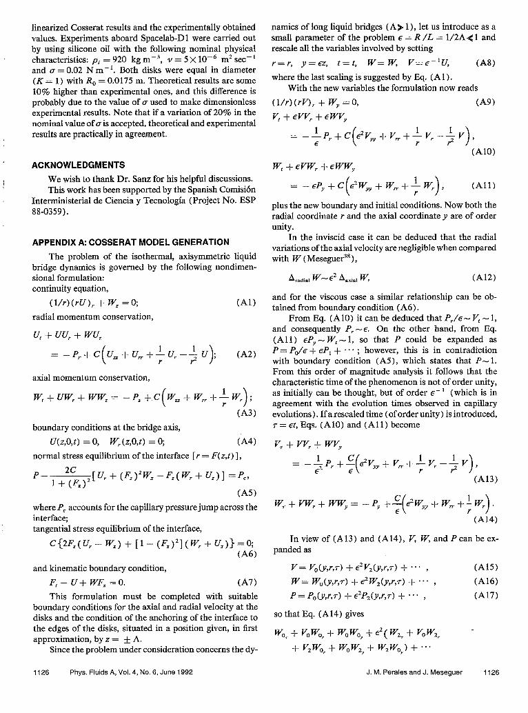
linearized Cosserat results and the experimentally obtained values. Experiments aboard Spacelab-Dl were carried out by using silicone oil with the following nominal physical characteristics: pi = 920 kg rns3, Y = 5 x lo-’ m* set-’ and (T = 0.02 N m-r. Both disks were equal in diameter (K = 1) with R, = 0.0175 m. Theoretical results are some 10% higher than experimental ones, and this difference is probably due to the value of (T used to make dimensionless experimental results. Note that if a variation of 20% in the nominal value of ais accepted, theoretical and experimental results are practically in agreement.
ACKNOWLEDGMENTS
! We wish to thank Dr. Sanz for his helpful discussions. This work has been supported by the Spanish Comision
Interministerial de Ciencia y Tecnologia (Project No. ESP 88-0359).
APPENDIX A: COSSERAT MODEL GENERATION
The problem of the isothermal, axisymmetric liquid bridge dynamics is governed by the following nondimen- sional formulation: continuity equation,
(l/r)(rU), + w, =o; (Al) radial momentum conservation,
u* -I- vu* f wu,
Z --P,+c u&J,+bJ+J ; >
t-42) r
axial momentum conservation,
w, + VW, + ww, = - P, + c w, -I- w, + 1 w, ( >
;
r (A3) boundary conditions at the bridge axis,
U(z,O,t) = 0, W,(z,O,t) = 0; (A4) normal stress equilibrium of the interface [r = F(z,t) 1,
p- 2c 1 -I- KY
cur + (I;:)2K -K(Wr + Uz>l =pc,
(A5) where PC accounts for the capillary pressure jump across the interface; tangential stress equilibrium of the interface,
c{2~,(U,--W,)+[1-(~,)2](W,+U,)}=0; (‘46)
and kinematic boundary condition, F, - U+ WFz =O. (A7) This formulation must be completed with suitable
boundary conditions for the axial and radial velocity at the disks and the condition of the anchoring of the interface to the edges of the disks, situated in a position given, in first approximation, by z = + A.
Since the problem under consideration concerns the dy-
1126 Phys. Fluids A, Vol. 4, No. 6, June 1992
namics of long liquid bridges (A) 1 ), let us introduce as a small parameter of the problem E = R /L = 1/2A< 1 and rescale all the variables involved by setting
r=r, y=ez, t=t, W= W, V==E-‘U, L48) where the last scaling is suggested by Eq. (A 1) .
With the new variables the formulation now reads
(l/r)(rV), + WY =O, v, + NV, + EWVy
(A91
= -‘p,+c E?Vyy+Vrr+~Vr-fV , E ( r >
(A101
w, + Evw; + EWWy
= -EP.Y+C 2wyy+wn.+~wr ( )
, (All) r
plus the new boundary and initial conditions. Now both the radial coordinate r and the axial coordinate y are of order unity.
In the inviscid case it can be deduced that the radial variations of the axial velocity are negligible when compared with W (Meseguer”a),
Aradial W- 2 &a~ W, t-412)
and for the viscous case a similar relationship can be ob- tained from boundary condition (A6).
From Eq. (AIO) it can be deduced that P/E- V, - 1, and consequently P, -E. On the other hand, from Eq. (All) eP,,- W,- 1, so that P could be expanded as P=P(Je++P, f*** ; however, this is in contradiction with boundary condition (A5), which states that P- 1. From this order of magnitude analysis it follows that the characteristic time of the phenomenon is not of order unity, as initially can be thought, but of order E- ’ (which is in agreement with the evolution times observed in capillary evolutions). If a resealed time (of order unity) is introduced, r= et, Eqs. (AlO) and (All) become
v, + vv, + WV,
= --$P,,C 2vyy+v~+-by~v), E ( r
(A13)
w,+vwr+wy= -Py+C Pw,+w,,+~w, ( >
. E r
(Al4)
In view of (A13) and (A14), V, W, and Pcan be ex- panded as
V= yO(y,r,d + 2V2(y,r,7> + *** ,
W= W,(y,r,d + iW2(y,r,7) + a-- , P = PoW,7) + 2P2(y,r,7) + - * * ,
so that Eq. (A14) gives
wo7 + vowor + wowo, + “( W& + vow*r
+ v,5 + w,wq, -I- W*W,) -t ***
(A15)
(A161 (AI7)
J. M. Perales and J. Meseguer 1126

= _ PO, - ‘P2, -f c E (
w-o,, + ” wo, r j
+ c (
ws, + w*,, f-L wz, -I- **. . r >
(A181
Note that if C- 1 the (s- ’ problem would give Worn + (l/r) Wo7 = 0, that is, W, = W,(y,t>, which, togeth- er with the above reasoning on the radial variation of W, seems to indicate that W, can be considered independent of r, not only for small viscosities and, consequently, it can be written as
W= Wo(y,t) + 2W2(w,t) + **a . (A19) For the radial velocity, V, taking into account the conti-
nuity equation, the expansion would be of the form
V= -~rWoyCY,t) +2V2(y,r,t> + -0. . (A201 On the other hand, the E- 2 problem in Eq. (A 13 ) gives
Po, = 0, so that
P=P,(y,t) + 2P2(y,r,t) + **- . (A21) The introduction of expansions (A19), (A20), and
(A21) in Eqs. (A8), (A13), and (A14) gives the following: Continuity equation:
(l/r)(rVJ)r + Wi, =0, j=2,4 ,... . (A221 Note that the continuity equation is fultilled automati-
cally at order unity [it was taken into account when expan- sion (A20) was postulated].
Radial momentum equation: Order 1,
-+rWo,+$r(Wo,)z--+rWoWoYY= -P2,;
(A23) order f’,
WoV2 Y
= - P4, + c (
- f rWoyy,, -k V2,, + -i V,, - -$ V2 )
. E r
Axial momentum equation: Order 1,
w,? + Kwq, = - PO,; order 2,
(A241
(~25)
Wzr - -+- r Wsy Tr + W. W2, + Wo, W,
s - P2, + c E
wo, + w,_ + L w2, r >
9 (A261
where it has been assumed that C-E. This formulation must be completed with the appropriate boundary and initial con- ditions.
In order to generate the so-called Cosserat model two steps shall be followed: first, in the order unity problem some terms that are of i order will be retained [this is not incon- sistent ifonly the O( 1) problem is solved]; and second, pres- sure terms will be eliminated from the formulation by using
boundary conditions at the interface. The resulting O( 1) problemis (in the following the subscript “0”has been omit- ted and the primitive variables have been recovered) :
-+r(( W, + WW,>, -$-( w~)z)
= - P, - -J- rCW,,, (A27)
w, + ww, = -P, + cw,, (A28)
where the underlined terms are of &‘- order and an additional 2 term in P, has been considered.
Boundary conditions at the interface now read
P(E?--C[l+(F,)*]-‘[w,(2(F,)*--1)
+FF,w,] =Pc, (~29)
@ ‘,W, =F[V”F,)2- I] W,, (A30) 2F, +FW, +2F,W=O, (A31) where Eq. (A3 1) can be reduced to the continuity equation of a slice (F’), + (F’W), = 0.
Equation (A27) states that P, must be linear in r (and of order .?), so that momentum equations (A27) and (A28) suggest that pressure is of the form
P(r,zJ> = IJAW + hiz,t), (~32) where h(z,t) - 1 and A(z,t) -iLgh(z,t). Introduction of this expression for Pin (A27) and (A28) gives
(w,+~),-tcw~)*=Zq+CW,,, (A33)
w,+ww,= -Pj~Az-h,+CW,. (A34) Observe that in Eq. (A34) all terms of order unity de-
pend only on z and t, but there is an additional retained term of order 2, which depends on r, z, and t. To eliminate r from the formulation, Eq. (A34) is substituted by its integral over a slice, that is,
F’( W, + WW,) = - dF4A, - F*h, + CF’W,. (A35)
Note that there are three unknowns: F(z,t), W(z,t), and P(r,z,t) [that is, A(z,t) and h(z,t) 1, and three equations: continuity equation and two momentum equations, (A33) and (A34). There are four boundary conditions at the disks (two at each one of the disks) and two more equations at the interface, (A29) and (A30). The formulation must be com- pleted, of course, with suitable initial conditions.
To eliminate pressure terms from the formulation, boundary conditions at the interface are rewritten as the equilibrium of the stresses in axial direction and in radial direction, instead of in the normal direction, Eq. (A29), and in the tangential direction, Eq. (A30). These conditions are, in the radial direction,
$F2A+h=C( - W,+jFF,W,) +P,, C-436)
and in the axial direction,
jF2-4+h=C zw,++;W,)+P,. (
(A37) I
Let us multiply Eq. (A33) by F4/8 and introduce the function .?P’ = &F4-4 + F*h (proportional to the integral of
1127 Phys. Fluids A, Vol. 4, No. 6, June 1992 J. M. Perales and J. Meseguer 1127

the pressure in each slice). Then, the second member of (A3 8 ) , taking into account the definition of 9 and (A36), becomes $F4A + iCF4W,
= F=(JF=A + h) - P + @TF4 W,
= - 9 $ gC [ (F4W& - SF’W,]
+ F=Pc, (A38) and the second term of (A35), with the help of (A37), can be written as
- $F4A, - F’h, + CF= W,
= - Yp, + 2FFr(iF2A f h ) + CF=W,
z=- 9, -j- 2C (F=W,), + (F=),P,; (A391
therefore the momentum equations become
F=( Wt + WW,) = - Yz + (F=),P, -t 2C(F=W&, (A@)
QF4[(K + ww,). --WC,‘]
= - :y + F’P, + $C [ (F4W& - 8F2W,],
(A411
which are identical to those known as Cosserat equations.
APPENDIX B: INTERFACE SHAPE ANALYSIS
The measurements of both the interface equilibrium shape and the deformation versus time of given sections when the liquid bridge is excited have been made by analyz-
FIG. 24. Typical image of a liquid bridge illuminated, as described in Ap- pendix B.
1
GREY LEVEL
0.6
0.4
0.2
0 -3 -2 -1 0 1 2 d [cm] 3
FIG. 25. Distribution of grey level along a horizontal line of the picture shown in Fig. 24. In this plot dindicates the distance from the liquid bridge axis.
ing the video image obtained by a CCD camera. It is of the utmost importance to choose the illumination system suited to the desired application. In these experiments, due to the difference in refractive index between the outer bath (water- methanol mixture) and the fluid of the liquid bridge (sili- cone oil), it is easy to obtain a highly contrasted image by using a uniform background illumination for only half of the field, in such a way that, when seen from the camera side, the border of the illuminated region coincides with the projec- tion of the liquid bridge axis (Fig. 24). A typical brightness profile of a horizontal line of the picture shown in Fig. 24 can be seen in Fig. 25. On the left side (d < - 1.5 cm), the illu- minated background region can be seen through the bath, whereas the right part (d > 1.5 cm) corresponds to the nonil- luminated region. The liquid bridge borders can be seen as a narrow dark band in the bright side (the left border) and a narrow bright band in the dark one (the right border), These bands correspond to the nonilluminated and illuminated re- gions of the opposite half background seen through the liq- uid bridge, which acts as a lens. In this way, the interface shape can be determined by looking at the point where the sharp transition between bright and dark occurs.
The image coming from the CCD camera, once digi- tized, is scanned line by line (the digitizer has a resolution of 5 12 lines of 5 12 pixels each) searching the pixels in which the transition from dark to bright occurs (the interface left bor- der ) and from bright to dark (the right one). The interface is assumed to be in the point where the illumination is 80% of the maximum (for the left border) and 20% (for the right one), as indicated in Fig. 25, and these points can be easily computed by linear interpolation between the grey levels of the two adjacent pixels. From this measurement the inter- face equilibrium shape can be determined (see Fig. 20) and stored in a few seconds. The recording of the liquid bridge
1128 Phys. Fluids A, Vol. 4, No. 6, June 1002 J. M. Perales and J. Meseguer 1128

evolution on a YTR has not been used because during analy- sis after the experiment it is difficult to synchronize consecu- tive images due to the degradation of the signal. Thus real time analysis has been preferred. Due to the limited comput- er capabilities, only the evolution with time of the diameter of given sections (three sections in the experiments per- formed) can be monitored at the video full rate (25 times per second).
‘W. R. Wilcox, “Zone refining,” Encycl. Chem. Technol. 24,903 ( 1984). ‘A. D. Myshkis, V. G. Babskii, N. D. Kopachevskii, L. A. Slobozhanin, and A. D. Tyuptsov, Low-Gravity FluidMechanics ( Springer-Verlag, Ber- lin, 1987).
‘J. M. Haynes, “Stability of a fluid cylinder,” J. Colloid Interface Sci. 32, 652 (1970).
“M. A. Erle, R. D. Gillette, and D. C. Dyson, “Stability of interfaces of revolution with constant surface tension. The case of the catenoid,” Chem. Eng. J. 1,97 (1970).
“R. D. Gillette and R. C. Dyson, “Stability of fluid interfaces of revolution between equal solid circular plates,” Chem. Eng. J. 2,44 ( 1971) .
OS. R. Coriell and M. R. Cordes, “Theory of molten zone shape and stabil- ity,” J. Cryst. Growth 42,466 (1977).
‘I. Martinez, “Floating zone. Equilibrium shapes and stability criteria,” in COSPAR Space Research XVIII (Pergamon, Oxford, 1978), p. 519.
“E. A. Boucher and M. J. B. Evans, “Capillary phenomena, Part XII. Prop- erties of fluid bridges between solids in a gravitational field,” J. Colloid
j Interface Sci. 75,409 ( 1980). 9L. A. Slobozhanin, “Problems on the stability of liquids in equilibrium, appearing in spatial technology,” in Hydromechanics and Heat and Mass Trarrsfer in Zero-Gmvity (Nauka, Moscow, 1982), Vol. 9 (in Russian).
I’M. J. Russo and P. H. Steen, “Instability of rotund capillary bridges to general disturbances, experiment and theory,” J. Colloid Interface Sci. 113, 154 (1986).
“J. M. Perales, “Non-axisymmetric effects on long liquid bridges,” Acta Astronaut. 15,561 ( 1987).
12E. A. Boucher and T. G. Jones, “Equilibrium and stability characteristics of zero-gravity fluid bridges constrained between equal solid rods,” J. Col- loid Interface Sci. 126,469 (1988).
*%. R. Coriell, S. C. Hardy, and M. R. Cordes, “Stability of liquid zones,” J. Colloid Interface Sci. 60, 126 ( 1977).
141. Da Riva and I. Martinez, “Floating zone stability (Exp. l-ES-33 1 ),” in ESA SP-142 (ESA Publication Division, ESTEC, Noordwijk, 1979), p. 79.
‘$5. Meseguer, “Stability of long liquid columns,” in ESA SP-222 (ESA Publication Division, ESTEC, Noordwijk, 1984), p. 297.
‘9. h([eseguer, “Stability of slender, axisymmetric liquid bridges between unequal disks,” J. Cryst. Growth 67, 141 (1984).
“I. Martinez and J. M. Perales, “Liquid bridge stability data,” J. Cryst. Growth 78,369 (1986).
‘*J. Meseguer, A. Sanz, and J. M. Perales, “Axisymmetric long liquid bridges stability and resonances,” Appl. Microgravity Technol. 2, 186 (1990).
?. Martinez “Floating zone under reduced gravity. Axisymmetric equi- librium sha’pes,” in E.SA SP-114 (ESA Publication Division, ESTEC, Noordwijk, 1976), p. 277.
“‘I. Martinez, “Stability of axisymmetric liquid bridges,” in ESA SP-191 (ESA Publication Division, ESTEC, Noordwijk, 1983)) p. 267.
“R. A. Brown and L. E. Striven, “The shapes and stability of captive rotat- ing drops,” Philos. Trans. R. Sot. London Ser. A 297, 5 1 ( 1980).
221. Da Riva, “Stability of liquid bridges,” in Applications of Space Technol- ogv (Pergamon, Oxford, 1981), p. 69.
“L. H. Ungar and R. A. Brown, “The dependence of the shape and stability of captive rotating drops op multiple parameters,” Philos. Trans. R. Sot. London Ser. A 306,347 (1982).
“4J. M. Vega and J. M. Perales, “Almost cylindrical isorotating liquid bridges for small Bond numbers,” in ESA SP-191 (ESA Publication Divi- sion, ESTEC, Noordwijk, 1983), p. 247.
=J. M. Perales, A. Sanz, and D. Rivas, “Eccentric rotation of a liquid bridge,” Appl. Microgravity Technol. 2, 193 ( 1990).
26W. Heywang, “Zur Stabilitat senkrechter Schmelzzonen,” Z. Natur- forschg. teil a 11, 238 (1956).
“I. Martinez and J. M. Perales, “Bidimensional liquid bridges in a gravity field,” .4cta Astronaut. 15. 567 (1987).
2sJ. M. Perales, J. Meseguer, and I. Martinez, “Minimum volume of axi- symmetric liquid bridges between unequal disks in an axial microgravity field,” J. Cryst. Growth 110, 855 (1991).
29A. Sanz, “‘The influence of the outer bath on the dynamics of axisymmet- ric liquid bridges,” I. Fluid Meoh. 156, 101 ( 1985).
‘OH. F. Bauer, “Natural frequencies and stability of immiscible cylindrical z-independent liquid systems,” Appl. Microgravity Technol. 1, 11 (1987).
“‘H. F. Bauer, “Natural frequencies and stability of circular cylindrical im- miscible liquid systems,” Appl. Microgravity Technol. 2,27 (1989).
“A. Gaiifin, “Anllisis modal de zonas liquidas axilsim&icas confinadas por tensi& superficial,” Tesis doctoral, Universidad de Sevilla, 1989.
33A. Sanz and J. tipez-Diez, “Non-axisymmetric oscillations of liquid bridges,” J. Fluid Mech. 20.5, 503 (1989).
341. Da Riva and J. Meseguer, “On the structure of the floating zone in melting,” Acta Astronaut. 5, 637 (1978).
351. Da Riva and D. R. Manzano, “Impulsive motions of the Aoating zone,” Physicochem. Hydrodyn. 2, 165 ( 198 1).
36G M Harriot and R. A. Brown, “Flow in a differentially rotated cylindri- cal drop at low Reynolds number,” J. Fluid Mech. 126,269 (1983).
“G. M. Harriot and R. A. Brown, “Flow in a differentially rotated cylindri- cal drop at moderate Reynolds number,” J. Fluid Mech. 144,403 (1984).
38J. Meseguer, “The breaking of axisymmetric slender liquid bridges,” J. Fluid Mech. 130, 123 (1983).
“J. Meseguer, “The influence of axial microgravity on the breakage of axi- symmetric slender liquid bridges,” J. Cryst. Growth 62, 577 (1983).
4oJ. Mestguer, “The dynamics of axisymmetric slender liquid bridges be- tween unequal discs,” J. Cryst. Growth 73, 599 (1985).
41.J. Meseguer, “Axisymmetric long liquid bridges in a time-dependent mi- crogravity field,” Appl. Microgravity Technol. 1, 136 (1988).
4*J. Meseguer, A. Sanz, and D. Rivas, “The breaking of axisymmetric non- cylindrical liquid brid&s,” in ESA SP-291 (ESA Publication Division, ESTEC, Noordwijk, 1983), p. 261.
43J. Meseguer and A. Sanz, “Numerical and experimental study of the dy- namics of axisymmetric liquid bridges,” J. Fluid Mech. 153, 83 ( 1985).
44J. Meseguer and A. Sanz, “One-dimensional linear analysis of the liquid injection or removal in a liquid bridge,” Acta Astronaut. 15,573 ( 1987).
45Y. Zhang and J. I. D. Alexander, “Sensitivity of liquid bridges subject to axial residual acceleration,” Phys. Fluids A 2, 1966 (1990).
46D. Rivas and J. Meseguer, “One-dimensional, self-similar solution of the dynamics of axisymmetric slender liquid bridges,” J. Fluid Mech. 138, 417 (1984).
“5 Meseguer and J. M. Perales, “A linear analysis of g-jitter effects on vis- cbus cylindrical liquid bridges,” Phys. Fluids A 3,2332 (1991).
4RG. C. Mason, “An experimental determination of the stable length of cy- lindrical liquid bubbles,” J. Colloid Interface Sci. 32, 172 (1970).
49A Sanz and I. Martinez, “Minimum volume for a liquid bridge between e&l disks,” J. Colloid Interface Sci. 93, 235 (1983).
5oJ. Meseguer, L. A. Mayo, J. C. Llorente, and A. FernBndez, “Experiments with liquid bridges in simulated microgravity,” J. Cryst. Growth 73, 609 (1985).
“J Meseguer, A. Sanz, and J. L6pez, “Liquid bridge breakages aboard Spacelab-Dl,” J. Cryst. Growth 78, 325 (1986).
s21 Martinez and A. Sanz, “Long liquid bridges aboard sounding rockets,” &A J. 9,323 (1985).
“A. Sanz and J. M. Perales, “Liquid bridge formation,” Appl. Microgra- vity Technol. 2, 133 (1989).
.i4J. R Carruthers and M. Grasso, “Studies of floating liquid zones in siniu- lated zero gravity,” J. Appl. Phys. 43,436 ( 1972).
“J. R. Carruthers, E. G. Gibson, M. G. Klett, and B. R. Facemire, “Studies of rotating liquid floating zones on Skylab IV,” AIAA Paper No. 75-692, 1975.
“5 R Carruthers, E. G. Gibson, M. G. Klett, and B. R. Facemire, “Studies . , of rotating liquid Boating zones on Skylab IV,” Prog. Astronaut. Aero- naut. 52,207 ( 1977).
s’R. Tagg, L. Cammack, A. Cronquist, and T. G. Wang, “Rotating liquid drops, Plateau’s experiment revisited,” Report No. JPL 900-954, Jet Pro- pulsion Laboratory, Caltech, Pasadena, CA, 1980.
“1. Martinez, “Liquid column stability,” in ESA SP-222 (ESA Publication Division, ESTEC, Noordwijk, 1984), p. 31.
591. Martinez, “Stability of long liquid columns in Spacelab-Dl,” in ESA SP-256 (ESA Publication Division, ESTEC, Noordwijk, 1987). p. 235.
“1. Martinez and J. Meseguer, “Floating liquid zones in microgravity,” in
1120 Phys. Fluids A, Vol. 4, No. 6, June 1002 J. M. Perales and J. Meseguer 1120
ScientiJc Results of the German Spacelab Mission DI (DFVLR, KBln, 1987), p. 105.
‘rM P Elagin, A. P. Lebedev, and A. V. Tsmelev, “Laboratory modeling of . . the stability and dynamics of free liquid zones,” in Hydromechanics and Heat and Mass Trans@r in Zero-Gravity (Nauka, Moscow, 1982), p. 24 (in Russian).
“1. Martinez, A. Same, J. M. Perales, and J. Meseguer, “Freezing of a liquid column on the Texus-18 Sounding Rocket Flight,” ESA J. 12, 483 (1988).
h3H. Gonzalez, F. M. J. MC Cluskey, A. Castellanos, and A. Barrero, “Sta- bilization of dielectric liquid bridges by electric fields in the absence of gravity,” J. Fluid Mech. 206, 545 (1989).
*A. E. Green, “On the nonlinear behavior of fluid jets,” Int. 3. Eng. Sci. 14, 49 (1976).
“D. B. Bogy, “Use of one-dimensional Cosserat theory to study instability in a viscous liquid jet,” Phys. Fluids 21, 190 (1978).
66D. B. Bogy, “Wave propagation and instability in a circular semi-finite
Iiquid jet harmonically forced at the nozzle,” J. Appl. Mech. 45, 469 (1978).
“D. B. Bogy, “Breakup of a liquid jet, thud perturbation Cosserat solu- tion,” Phys. Fluids 22, 224 (1979).
68D. B. Bogy, “Drop formation in a circular liquid jet,” Annu. Rev. Fluid Mech. 11,207 (1979).
b9A. Sanz-And&s, J. M. Perales, P. Rodriguez de Francisco, and A. Sanz- Lobera, “A Plateau Tank Facility (PTF) for liquid bridge experimenta- tion by using buoyancy technique for microgravity simulation,” in ES’A SP-29.5 (ESA Publication Division, ESTEC, Noordwijk, 1990), p. 607.
“C. Bisch, A. Lasek, and H. Rodot, “Comportement hydrodynamique de volumes liquides spheriques semi-libres en apesanteur simulee,” J. M&c. Theor. Appl. 1, 165 (1982).
“A. Sanz, “Comportamiento de las zonas liquidas flotantes en micrograve- dad simulada,” Tesis doctoral, Universidad Politecmica de Madrid, 1983.
‘zJ. J. Stoker, Nonlinear Vibrations (Interscience, New York, 1966), Vol. II.
1130 Phys. Fluids A, Vol. 4, No. 6, June 1992 J. M. Perales and J. Meseguer 1130