theoretical and experimental evaluation of a low … and experimental evaluation of a low...
TRANSCRIPT

Theoretical and Experimental Evaluation of a Low
Temperature Lithium-Bromide/Water Absorption
System
D.H. Jeggels and R.T. DobsonDepartment of Mechanical and Mechatronic Engineering
University of Stellenbosch, South Africa
[email protected], [email protected]
Centre for Renewable and Sustainable Energy Studies
17 November 2011
Abstract
With an increasing desire that the generation of power occurs in an en-vironmentally friendly manner, new technologies have to be developed whileolder technologies can be re�ned or implemented in innovative manners. Anolder technology that has been garnering attention over the last few decadesis vapour absorption. A vapour absorption system is driven by a source ofheat and is typically used to produce refrigeration, but the possibility for theincorporation of power generation into vapour absorption has been consideredin the past and has to be further investigated.
The primary goals of this study are the development of a steady statesimulation; the design, construction and control of a vapour absorption sys-tem as well as the identi�cation of manners in which to recover and utilizelow temperature waste heat using vapour absorption. Secondary goals thatmay be incorporated into the study are the development of a transient sim-ulation of a vapour absorption system as well as the theoretical and possiblyexperimental implementation of a turbine for power generation. It is hopedthat this relatively exploratory study will assist future research in the �eld ofvapour absorption at Stellenbosch University and in South Africa.
Keywords: Waste Heat Recovery, Vapour Absorption, Dual Function Vapour Absorption
1 Introduction
Improvements in the overall e�ciency at which a large system or plant operates canhave signi�cant implications to performance and operation costs and due to thisthere has always been a desire to increase the e�ciency at which industrial processesoperate. In a situation where the overall operating e�ciency of, for example, acoal �red or nuclear power plant is improved, it would reduce the amount of fuelrequired to produce a similar amount of energy thereby reducing the pollution thatis generated by the plant as well as reducing the running costs of the plant. Whileit is desired that the e�ciency of a process be as high as possible, there is always an

upper limit to the extent in which the e�ciency of a plant can be improved beforeany additional improvements will simply no longer be feasible from an economicalpoint of view.
A resource that is largely untapped in many processes is the waste heat streamsthat are generated which are simply �thrown away� into the environment. Thisprocess heat that is discarded is referred to as waste heat and the possibility ofrecovering and reusing this energy can improve the overall e�ciency at which a pro-cess operates at. A large portion of waste heat is only available at low temperaturesand there are few viable methods for the recovery and utilization of waste heat thathas a low temperature. One of the methods for the recovery of low temperaturewaste heat is vapour absorption.
What makes vapour absorption cycles an attractive technology is that the systemis thermally activated systems where the vast majority of the energy requirementsof the system can be provided by a source of low temperature heat such as heatingwater from a solar panel or a low temperature source of waste heat. Althoughvapour absorption is old technology it is not as widely known as more mainstreamtechnologies like the vapour compression cycle as it lost popularity in the early 19thcentury due to the advantages o�ered by vapour compression technology.
To better understand and theoretically simulate the operation, heat transferand working �uid behaviour in a vapour absorption system it is intended that anexperimental system be designed. The engineering work done to date in this regardwill be presented. The derivation of the theoretical model describing the behaviouras well as the implementation of it in a simulation will be discussed. Conclusionsand recommendations based on the based on the work that has been performed willbe made.
1.1 Waste Heat Recovery
Whether it is cooling water, a process stream or the exhaust from a kiln or furnacethere are numerous process in which there is potential for the recovery of processheat. In place of either cooling down these process streams for the purpose of reuseor discarding them into the atmosphere or the ocean the goal of waste heat recoveryis to facilitate the capture of the energy contained in a waste stream and use it fora practical purpose. Waste heat recovery can be used to generate power, preheatanother stream or generate cooling via a refrigeration process.
There are many complications in the implementation of a waste heat recoverysystem which contribute as to whether or not it is viable which include the tem-perature and quality of the waste stream, heat exchanger material selection as wellas size, possible corrosive or radioactive contaminants present in the waste stream,capital costs of the waste heat recovery system, the costs of altering and retro�ttingan existing system and even the political policy can contribute as to whether wasteheat recovery methods are attractive. There are also occasions when it is physicallyunrealistic to attempt a recovery of waste heat. The addition complications associ-ated with the implementation of waste heat recovery do not form part of the goalsof this study and will not be further discussed.
1.1.1 Sources of Waste Heat
In a 2008 report evaluating waste heat recovery opportunities in the United States itwas found between 20 and 50 % of the energy that is used in industrial processes islost as waste heat [1]. It was also estimated that roughly 60 % of all waste heat is ata low temperature which shows that if the methods of recovering low temperaturewaste heat became more e�ective and thereby more attractive the possibility existsthat a signi�cant quantity of energy could be recovered.
There are numerous sources of waste heat in a wide variety of industrial processesand is typically classi�ed into three di�erent categories by the temperature of thewaste heat. These categories are high, medium and low temperature waste heat.Depending on the literature that is referenced, the values which determine theboundaries of these groupings can vary but for the purposes of this project thetemperature range of the three di�erent classes of waste heat will be de�ned as:
� High Temperature Waste Heat: above 650 �
� Medium Temperature Waste Heat: from 200 to 650 �
� Low Temperature Waste Heat: below 200 �
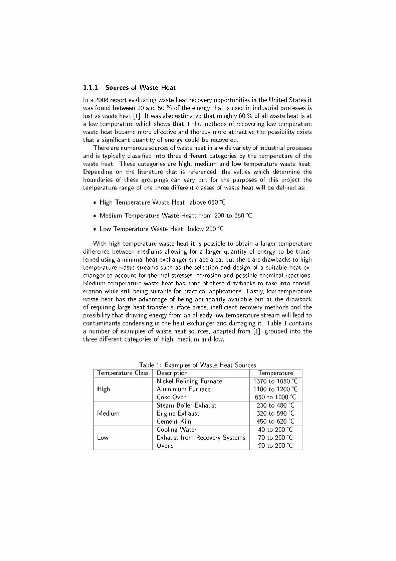
With high temperature waste heat it is possible to obtain a larger temperaturedi�erence between mediums allowing for a larger quantity of energy to be trans-ferred using a minimal heat exchanger surface area, but there are drawbacks to hightemperature waste streams such as the selection and design of a suitable heat ex-changer to account for thermal stresses, corrosion and possible chemical reactions.Medium temperature waste heat has none of these drawbacks to take into consid-eration while still being suitable for practical applications. Lastly, low temperaturewaste heat has the advantage of being abundantly available but at the drawbackof requiring large heat transfer surface areas, ine�cient recovery methods and thepossibility that drawing energy from an already low temperature stream will lead tocontaminants condensing in the heat exchanger and damaging it. Table 1 containsa number of examples of waste heat sources, adapted from [1], grouped into thethree di�erent categories of high, medium and low.
Table 1: Examples of Waste Heat SourcesTemperature Class Description Temperature
HighNickel Re�ning Furnace 1370 to 1650 �Aluminium Furnace 1100 to 1200 �Coke Oven 650 to 1000 �
MediumSteam Boiler Exhaust 230 to 480 �Engine Exhaust 320 to 590 �Cement Kiln 450 to 620 �
LowCooling Water 40 to 200 �Exhaust from Recovery Systems 70 to 200 �Ovens 90 to 200 �

1.1.2 Methods of Waste Heat Recovery
It is possible to classify methods of waste heat recovery to internal and externalmethods. Where internal methods of waste heat recovery transfer thermal energyfrom one location or stream in a system to another location in the system. Whileexternal methods of waste heat recovery would be the production of electricity orfor example refrigeration by fuelling an entirely separate external system with thewaste heat stream. Examples of methods for internal waste heat recovery are arecuperator, a regenerator or a heat exchanger for pre-heating. External methodsof waste heat recovery would be the implementation of a Rankine cycle, an OrganicRankine cycle, a Kalina cycle or a vapour absorption cycle.
The methods available for waste heat recovery are also dependant on the tem-perature of the waste heat stream from which it is desired to recover waste heat asdi�erent methods of waste heat recovery are most e�cient under certain operatingtemperatures. Of the methods previously mentioned, the Rankine cycle would beused to recover high temperature waste heat, the Organic Rankine cycle for mediumtemperature waste heat and the Vapour absorption cycle for low temperature wasteheat. While only a few examples of methods for waste heat recovery were discussed,the focus of this project is on the Vapour absorption cycle and due to this additionalmethods of waste heat recovery will not be discussed further.
1.2 Absorption Cycles
In order to introduce the operation of a vapour absorption system, the similaritiesbetween a vapour absorption and vapour compression system will be discussed.In the case of a typical vapour compression refrigeration system, the system isdriven by a compressor which is powered by an electric motor whereas a vapourabsorption system is driven by a source of heat. In Figure 1, a schematic of a vapourcompression system can be seen where the working �uid or refrigerant of the systempasses through the evaporator and evaporates thereby cooling an external streamafter which the refrigerant is compressed to a higher pressure and temperature beforeit passes through a condenser where energy can be removed from the refrigerant.Thereafter, the refrigerant passes through an expansion device and continues to theevaporator where it can continue the operational cycle.
WCompressor
QRefrig
QCondeser
Figure 1: Type I Heat Pump Using a Compressor

Wpump
QRefrig
QCondeser
QAbsorber
QGenerator
Figure 2: Type I Heat Pump Using the Principle of Vapour Absorption
Figure 2 shows the schematic diagram of a vapour absorption system where,similarly to a vapour compression system, a high temperature, high pressure re-frigerant in vapour form is cooled in a condenser, after which it passes throughan expansion device to an evaporator where it can provide cooling to an externalstream. This is where the similarities between the vapour absorption and compres-sion cycles end. In the case of a vapour absorption system, once the refrigerant isevaporated it enters the absorber where the vapour refrigerant is absorbed into theliquid solution. Due to the properties of the substances used in a typical vapourabsorption system, the absorption of refrigerant vapour into the liquid solution isan exothermic process and because of this, the liquid solution has to be cooled inorder to ensure operation of the system. The electric pump is used to pump theliquid solution to the generator, which is in the high pressure side of the system,where the liquid solution is heated and a small portion of the refrigerant is boiledo�. A medium that has been heating by the sun can be used to heat the liquidsolution in the generator, but the source of heat that is of interest to this project isprocess heat or waste heat. While a portion of the refrigerant is boiled o� the liquidsolution the remainder of the liquid solution, which is warmer than it was when itentered the generator, returns to the absorber and the refrigerant that was boiledo� continues to the condenser.
The purpose of the solution heat exchanger is to transfer energy from the hotsolution returning to the absorber from the generator to cooler stream that is en-tering the generator. A vapour absorption system will function without a solutionheat exchanger, but the inclusion of a solution heat exchanger will improve thecoe�cient of performance (COP) of the system by reducing the amount of energyneeded to heat the solution in the generator as well reducing the amount of energythat has to be removed from the system in the absorber.

Another means of highlighting the di�erences between the operation of a vapourcompression cycle and a vapour absorption cycle is to investigate the manner inwhich the COP is de�ned for the two di�erent systems. COP is de�ned as the ratiobetween the quantity of useful work produced by the system and the amount ofenergy or work supplied to the system. In the case of a vapour compression system,where QRefrig is the amount of refrigeration work that the system provided andWCompressor is the amount of work that the compressor required to drive the system,the following equation describes the COP:
COPV CS = QRefrig/WCompressor (1)
Whereas for a vapour absorption cycle the manner in which the system is pow-ered di�ers with the vapour compression system, the amount of energy supplied tothe system is compromised of the quantity of heat energy that is supplied to thegenerator or QGenerator as well as the work performed by the pump, WPump. Theamount of energy required to pump the liquid solution is signi�cantly smaller thanthe QRefrig and QGenerator and due to this it is at times ignored in the calcula-
tion of the COP. The sum of these two quantities, QGenerator and WPump, is thetotal amount of energy which is supplied to the system to produce the refrigerationQRefrig.
COPV AS = QRefrig/(QGenerator + WPump) (2)
Although the COP of a vapour absorption system is typically lower than 1 andtherefore lower than the typical COP of a vapour compression system, it can bereasoned that due to the vapour absorption system being driven by a resource thatwould have been thrown away instead of electrical energy in the case of a compressordriven system that its operational costs are less than those of a vapour compressionsystem. This advantage of reduced operational costs by recovering waste heat areo�set by the capital costs associated with the construction of a vapour absorptionsystem, but the cost analysis of a vapour absorption system is beyond the scope ofthis document and will not be discussed further.
1.2.1 Working Fluid
In a vapour absorption system the working �uid is made up of a two, or in specializedcases three, substances where these two substances are referred to as the sorbentand the refrigerant. In this document, this pair of substances is referred to as theliquid solution. The function of the sorbent is to absorb the �uid refrigerant andallow it to be boiled o� at a lower temperature than would be possible if it wasa pure substance. There are numerous criteria which a pair of substances have toful�l in order to be viable for use in an absorption system and it has been shownthat many combinations are feasible [5], but this will not be discussed further inthis document (for additional information please refer to [6]).
When working with a liquid solution composed of two substance such as thecombinations of water/lithium-bromide and ammonia/water the concentration ofthe solution has to be de�ned in order to properly describe the state of the solution.Equation 3 describes the manner in which the concentration of a solution is de�nedand it can be seen from the manner in which concentration is de�ned that as thesolution loses refrigerant in the generator, the concentration of the solution willincrease. The solution entering the generator is often referred to as the �weak�

solution and as a portion of the refrigerant is boiled o�, the concentration increasesand leaves the generator. This solution leaving the generator is referred to as the�strong� solution as it is stronger in sorbent than when it entered.
C = masssorbent/(massrefrigerant + masssorbent) (3)
Currently the most widely used combinations are ammonia/water, water/lithi-um-bromide and ammonia/hydrogen/water [7]. Where ammonia/hydrogen/waterare typically used in caravan and hotel fridges and ammonia/water as well water/lith-ium-bromide are widely used to provide for refrigeration. In an ammonia/watersystem it is possible to provide for refrigeration at temperatures below zero degreesCelsius due to ammonia being the refrigerant while in the case of a water/lithium-bromide system, water is the refrigerant and this limits the system's refrigerationpotential to temperatures above the freezing point of water. An additional drawbackof water/lithium-bromide is that there is the possibility that under speci�c condi-tions, the solution crystallizes which will lead to the system ceasing to function ina proper manner.
Although an ammonia/water and a water/lithium-bromide system can be repre-sented in a very similar schematic diagram the actual physical characteristics di�ervastly. An ammonia/water system operates at pressures well above atmosphericpressure and requires large pressure vessels while a water/lithium-bromide systemoperates at vacuum which in itself has its own complications. Additionally, in anammonia/water system the vapour produced in the generator is not pure ammoniaand if the water present is not removed it will negatively a�ect the operation of thesystem [2]. Material selection also has to be taken into account as copper and itsalloys cannot be used in the presence of ammonia and with the water/lithium-bro-mide system if the quality of the vacuum is not satisfactory, the liquid solution willcorrode copper and steel.
Due to the complications and hazards associated with the use of ammonia, itwas decided to focus on water/lithium-bromide vapour absorption technology forthis project. In addition to this, it was desired that it be possible to visually inspectthe operation of the vapour absorption system and this would be infeasible withammonia/water system.
The properties of a liquid solution like water/lithium-bromide are available inliterature. The American Society of Heating, Refrigerating and Air-Conditioning En-gineers fundamentals handbook [6] contains tables, graphs and equations detailingthe properties of water/lithium-bromide as well as ammonia/water. The enthalpy ofsaturated water or steam is a function of only temperature, but for liquid solutionslike water/lithium-bromide the enthalpy of the liquid solution is dependant on thetemperature and the concentration of the solution, this can be seen in Figure 3.
1.2.2 Dual Function
Vapour absorption technology has been used for a signi�cant amount of time togenerate refrigeration [3], but the possibility to generate electricity from a vapourabsorption cycle by incorporating a turbine and electrical generator has been previ-ously considered and investigated [4, 8]. The concept of �dual function� applied to avapour absorption system would be that the system either generates power or refrig-eration depending on the demand of environmental conditions, but the possibilityexists that both power and refrigeration can be provided concurrently.

Figure 3: Enthalpy Diagram for Water/Lithium-Bromide
Figure 4 shows the schematic layout of a dual function absorption system (DF-VAS) where the condenser and expansion device have been replaced by a turbine.The shaft of the turbine would be connected to a electrical generator to produce us-able electricity while the heat exchanger can provide for refrigeration. An additionalcomponent that is included is the super-heater which is implemented to ensure thatthe vapour entering the turbine is at the highest possible temperature based onthe temperatures available to the system. The vapour generation and absorptionportion of system would operate as a typical vapour absorption system. The refrig-erant would be undergo additional heating before passing through the turbine andthe evaporative heat exchanger to be absorbed back into the liquid solution in theabsorber. Due to the incorporation of additional components into the dual functionsystem, the COP for a dual function vapour absorption system would be de�ned as:
COPDFV AS = (QRefrig + WTurbine)/(QSuper−heater + QGenerator + WPump)(4)
Where the useful outputs of the system are the refrigeration work, QRefrig,and the shaft output of the turbine, WTurbine. Similarly to the typical vapourabsorption system, the system required heat in the generator and pump work but inthis con�guration of a dual function system, additional energy is added to super-heatthe vapour entering the turbine.

Wpump
QRefrig
WTurbine
QAbsorber
QGenerator
QSuper−heater
Figure 4: Schematic of a Dual Function Vapour Absorption System
1.3 Objectives
The objectives of this project all build towards the future, further investigation anddevelopment of a dual function vapour absorption system. The activities that areplanned for this project are:
� Steady State Simulation
� Experimental Apparatus
� Veri�cation of Steady State Simulation:
� Transient Simulation
The development of a steady state simulation that describes an operating pointof a vapour absorption system will be the �rst objective of the project. The de-sign, fabrication and operation of an experimental apparatus will not only help inattaining a greater understanding of the behaviour of a vapour absorption system,but will allow for the results obtained from the theoretical simulation to be veri-�ed. An additional bene�t of having an operational vapour absorption system inthe university will be that it can be incorporated into other projects in the future.The development of a transient simulation to describe the transient behaviour of avapour absorption system may be incorporate into the study.

2 Proposed Methods
To model the steady state operation of a vapour absorption system, the systemwas broken up into four main control volumes upon which the principles of theconservation of energy and the conservation of mass were applied. Thereafter, acomputer program was developed to iteratively solve for a steady state solution.
2.1 Theory
This subsection of the report will illustrate and describe the manner in which thecontrol volumes were established for the major components of the vapour absorptionsystem and how the steady state versions of the conservation of mass (Equation5) and the conservation of energy (Equation 6) were applied to them. Equation 7shows the manner in which the heat transfer in the components will be handled.Due to the size limitations of this document the complete derivation of the all of theequations that describe the di�erent control volumes in the components cannot bediscussed, but the equations of importance will be discussed for each component.
0 =∑
mi −∑
mo (5)
0 =∑
mi × hi +∑
Qi −∑
mo × ho −∑
Qo (6)
Q = UA× ∆T (7)
The function of the generator is to separate a portion of the refrigerant fromthe liquid solution and this is done by heating the solution via a heat exchanger.Figure 5 shows the streams that are of relevance to the generator. Which includethe waste heat stream passing through the heat exchanger, the �weak� stream ofsolution entering the generator and the �strong� solution leaving it after a portion,mevap, was boiled o�.
mGhw,TGhwi
mGhw,TGhwo
mevap,TGv
Phigh
mweak,TGli,Cweak
mstrong,TGlo,
Cstrong
TG
Figure 5: Model of Generator Streams

The conservation of mass applied to the total mass �ow rates passing throughthe generator and the total mass �ow rate of lithium-bromide passing through thegenerator yields the following equations:
mstrong = mweak − mevap (8)
Cstrong = (mweak × Cweak)/mstrong (9)
The following equation describes the amount of energy that will be transferredto the liquid solution via the heat exchanger:
QGenerator = UAG × (TGhw − TG) (10)
The conservation of energy applied to the entire generator gives the followingequation:
0 = mweak.hGli − mstrong.hGlo − mevap.TGv + QGenerator (11)
Where, after substituting equations rearranging the equation with TG as thesubject of the formula gives:
TG = TGhw + (mweak.hGli − mevap.hGv − (mweak − mevap).hGlo)/(UAG) (12)
When the conservation of energy and that of mass is applied to the the streamsof the condenser as seen in Figure 6, the following equation for the value of theliquid refrigerant can be derived:
TC = TCcw + (mevap.hGv − mevap.hCsat)/(UAC) (13)
mCcw,TCcwo
mCcw,TCcwi
mevap,TGv
mevap,TCsat
Phigh
Figure 6: Model of Condenser Streams

mGhw,TGhwi
mGhw,TGhwo
mevap,TE ,XEi
mevap,TE ,XEoPlow
Figure 7: Model of Evaporator Streams
In a similar fashion an equation for the temperature in the evaporator, see Figure7, can be derived:
TE = TEcw + (mevap.hCsat − mevap.hE)/(UAE) (14)
When determining an equation for the last of the major components, the ab-sorber seen in Figure 8, the following equation is derived:
TA = TAcw + (mevap.hE + (mweak − mevap).hGlo − mweak.hA)/(UAA) (15)
The pressures in the in the system are dependant on the temperature at whichcondensation and evaporation is occurring. The �high� and �low� pressures of thesystem can be calculated from a saturation pressure function:
Phigh = Psat(TC) (16)
Plow = Psat(TE) (17)
mAcw,TAcwi
mGhw,TAcwo
mevap,TE ,XEo
Plow
mpump,TA,Cweak
mstrong,TAli,CAli,XAi
Figure 8: Model of Absorber Streams

2.2 Computer Program
The equations described in the previous section were incorporated into a computersimulation written in SciLab ©, the equations describing the properties of wa-ter/lithium-bromide [6] as well as water [9] were also incorporated into the program.The program starts with declaring the values of the external streams that heat thegenerator, cool the condenser, undergo cooling in the evaporator and cool theabsorber. Thereafter initial assumptions are made for the temperatures in the fourmain components of the system, after which the iterative calculation of a steadystate solution begins. Figure 9 shows the process in which the computer codeattempts to determine the steady state operating point of a vapour absorptionsystem.
begin
Initial Values:
TGhwi,mGhwi,Cweak
TCcwi,mCcwi, ..
Initial Guesses:
TG = TGhwi − 20K,
TC = TCcwi + 10K, ..
ifδ < δallowed
Yes No
Recalculate Values:
TGnew = f(TGli, UAG,..)
TCnew = f(TCcwi, UAC ,..)
Compute Error:
δ =| TGnew − TG | + . . .
end
Figure 9: Flow Diagram
The solution heat exchanger was not included in the current version of thetheoretical simulation. This was done in order to focus on the operation of the fourmajor components of the vapour absorption system and will not have a signi�cantimpact on the results.
3 Research Methodology
After the completion of the literature study, work began on the steady state simula-tion as well as the experimental apparatus. Results obtained from the steady statesimulation can be compared with results found in literature. Once the experimentalapparatus is operation it will be possible to obtain experimental results. Also, thesteady state simulation will be adjusted to incorporate the physical characteristicsof the experimental apparatus and thereafter it will be possible to make an assess-ment as to validity of the results obtained in the simulation. Once this has been

completed it will be possible to make an assessment concerning whether or not theresults of the project have ful�lled the initial goals and objectives of the project.
4 Results
As far as the theoretical simulation of a vapour absorption system are concernedthe current approach that is implemented to simulate the operating conditions of avapour absorption system as seen in the previous section produces feasible results asseen in seen Table . There are various simulation packages that are used to simulatethe operation of a vapour absorption system, but these packages are not currentlyaccessible to the author in order to verify the results. In addition to this,
Table 2: Results from Theoretical SimulationSymbol Value
InputsUAG 400 W/(m.K)UAC 1600 W/(m.K)UAE 800 W/(m.K)UAA 500 W/(m.K)TGhwi 85 �TCcwi 25 �TEcwi 12 �TAcwi 25 �Cweak 50 %mweak 0.03 kg/s
OutputsTG 63.80 �TC 28.07 �TE 7.01 �TA 36.09 �Phigh 3799.17 PaPlow 1003.04 Pa
QG 6479.83 W
QG 4918.57 W
QG 3988.91 W
QG 5546.56 WCOP 0.615mevap 0.001983 kg/sCstrong 54.54 %

5 Conclusions and Recommendations
The initial direction that this project had was the implementation of an ammo-nia/water system and the design for an experimental apparatus using ammonia/wa-ter system was started, but due to the complications attached to the use of thecombination of ammonia/water the decision was made to focus on simulating andconstructing a water/lithium-bromide system. Progress has been made with the-oretical simulation of a vapour absorption system, but the validity of the resultsobtained has not been extensively veri�ed. The design of the water/lithium-bro-mide experimental apparatus is currently in its fourth iteration and once the designhas been �nalized, the construction of the apparatus will commence.
The project will continue from its current state with the �nalization of thedesign for the experimental apparatus, followed by the construction and operation.Concurrently with the work on the experimental apparatus, improvements will bemade to the computer simulation. Once the experimental apparatus is operation itwill be possible to gather experimental data from the system which.
There is still a signi�cant amount of work to be performed in order to completethe goals of the project and although alterations have been made to the plannedmanner in which the goals would be achieved, the goals of the project are still withinreach.
References
[1] Waste Heat Recovery: Technology and Opportunities in U.S. Industry. Technicalreport, BCS Incorporated, 2008.
[2] José Fernández-Seara and Jaime Sieres. The importance of the ammonia pu-ri�cation process in ammonia-water absorption systems. Energy Conversion andManagement, 47:1975�1987, 2006.
[3] W.B. Gosney. Principles of Refrigeration. Camridge, 1982.
[4] Shaoguang Lu and D. Yogi Goswami. Theoretical analysis of ammonia-basedcombined power/refrigeration cycle at low temperatures. In Sunrise on theReliable Energy Economy, 2002.
[5] R.A. Macriss and T.S. Zawacki. Absorption �uids data survey. Technical report,Institue of Gas Technology, 1989.
[6] Mark S. Owen, editor. ASHRAE Handbook � Fundamentals. ASHRAE, 2009.
[7] Pogsind Srikhirin, Satha Aphornratana, and Supachart Chungpaibulpatana. Areview of absorption refrigeration technologies. Renewable & Sustainable EnergyReviews, 5:343�372, 2001.
[8] G. Tamm, D.Y. Goswami, S. Lu, and A.A. Hasan. Theoretical and experimen-tal investigation of an ammonia-water power and refrigeration thermodynamiccycle. Solar Energy, 76:217�288, 2004.
[9] W. Wagner, J. R. Cooper, A. Dittmann, J. Kijima, H.-J. Kretzschmar, A. Kruse,R. Mares, K. Oguchi, H. Sato, and I. Stocker. The IAPWS Industrial Formula-tion 1997 for the Thermodynamic Properties of Water and Steam. Journal ofEngineering for Gas Turbines and Power (ASME), 122:150�182, 2000.