theoretical analysis of absorption chiller system
TRANSCRIPT

THEORETICAL ANALYSIS OF ABSORPTION CHILLER SYSTEM
MOHD HAFEEZ BIN ALIAS
A report submitted in partial fulfilment of the requirements
for the award of the degree of
Bachelor of Mechanical Engineering
Faculty of Mechanical Engineering
UNIVERSITY MALAYSIA PAHANG
DECEMBER 2010

iv
ACKNOWLEDGEMENTS
I am grateful and would like to express my sincere gratitude to my supervisor
Encik Amir Bin Abdul Razak for his germinal ideas, invaluable guidance, continuous
encouragement and constant support in making this research possible. He has always
impressed me with his outstanding professional conduct, his strong conviction for
science, and his belief that a degree program is only a start of a life-long learning
experience. I appreciate his consistent support from the first day I applied to graduate
program to these concluding moments. I am truly grateful for his progressive vision
about my training in science, his tolerance of my naive mistakes, and his commitment to
my future career.
My sincere thanks go to all my members of the student of the Mechanical
Engineering who helped me in many ways and made my stay at UMP pleasant and
unforgettable.
I acknowledge my sincere indebtedness and gratitude to my parents for their
love, dream and sacrifice throughout my life. I cannot find the appropriate words that
could properly describe my appreciation for their devotion, support and faith in my
ability to attain my goals. Special thanks should be given to my committee members. I
would like to acknowledge their comments and suggestions, which was crucial for the
successful completion of this study.
v
ABSTRACT
Absorption chiller is a cooling system that uses heat instead of electricity to cool
something. The different types of absorption chillers are solar, water, gas, and bromide
with steam. The process to cool a building with an absorption chiller is similar to that
used by conventional air conditioning systems in that there is compressor, condenser,
and evaporator equipment within the system. Refrigerant, normally lithium bromide is
subjected to pressure and builds up heat in the compressor. As the pressure and heat
build, the liquid is converted to a vapor gas. The gas then moves to the condenser where
the heat dissipates and it is turned back into a liquid. The cooled liquid is directed into
the evaporator, where it turns into a gas and pulls heat from the air; fan blowers send the
cool air into the building. The gas moves from the evaporator into the compressor and
the process starts again. In traditional air conditioning systems, this process is achieved
with the use of an electric powered pump. In a gas absorption chiller, the pump is run by
a natural gas line attached to the system. When the system is powered on, the natural
gas activates the pump to flow refrigerant through the compressor. These systems run
more efficiently than electric air conditioning systems but are still more costly to
operate than solar varieties. In areas where sunlight is not available for extended periods
of time, a gas absorption chiller is more often used. As we know that the COP of
absorption chiller is low to be compared with the refrigerant system. This problem
actually can be resolved by doing an analysis and a study of each component in the
absorption chiller especially the condenser that plays the main role to remove heat from
the system. It will be a good system if the condenser can remove heat as much as
possible. Normally, we will use a forced type of air condenser which uses a fan to blow
out the heated air from the system. It also the same with an evaporator but differently
functions as the evaporator has a great capacity when the temperature differences
between outlet and inlet is high. Talking about capacity, it surely will relate to
resistance in the evaporator. The metal is known to offer less resistance but it actually
depends on what type of refrigerant we are going to use. Iron and steel are very suitable
for ammonia while brass and copper are for the other type of refrigerant. It is very
important to have a high velocity for the flow of refrigerant and fluid over the
evaporator. For the generator, it is an energy source for the absorption chiller system
and usually the direct flow and heat pipe evacuated tube collector solar will be used as
the generator because of their potential and efficiencies even though it is the reason why
the absorption is highly cost. To determine the efficiency of a system, it can be shown
by a COP for the system. For new condenser concept will lowering the condensing
temperature. Hence the cooling capacity will increased. So it could enable the
compressor to operate at higher load for more longer time. Other than that, chiller with
higher cooling capacity could carry a higher loads with higher COP.

vi
ABSTRAK
Absorption chiller adalah sistem pendingin yang menggunakan haba sebagai ganti
kepada tenaga elektrik untuk menyejukkan sesuatu. Perbezaaan yang ada dalam
absorption chiller ialah solar, air, gas dan bromida bersama stim. Proses untuk
menyejukkan bangunan menggunakan absorption chiller adalah sama seperti
menggunakan system penyejukkan biasa yang mengandungi komponen seperti
compressor, condenser dan evaporator di dalam system itu. (refrigerant), yang biasa
digunakan ialah litium bromida yang dikaitkan dengan tekanan dan untuk meningkatkan
haba didalam compressor. Bila tekanan dan haba ditingkatkan, cecair akan ditukarkan
ke gas stim. Gas itu kemudiannya akan bergerak ke condenser dimana haba dibebaskan
dan bertukar semula bentuk cecair. Cecair yang sejuk akan ke evaporator diamana dia
akan bertukar bentuk ke gas semula dan menarik haba daripada udara. Alat peniup akan
menghantar udara sejuk kedalam bangunan. Gas itu akan bergerak dari evaporator ke
compressor dan proses yang sama akan berulang semula. Dalam sistem penyejukkan
biasa, proses ini akan berlaku dengan menggunakan pam elektrik. Manakala didalam
absorption chiller, pam digerakkan menggunakan gas semulajadi yang terdapat didalam
sistem itu. Bila sistem itu dihidupkan, gas semulajadi akan mengaktifkan pam untuk
menghantar refrigerant melalui compressor. Sistem ini beroperasi dengan lebih cekap
dibandingkan dengan pendingin hawa elektrik tetapi masih mahal kerana menggunakan
sistem solar. Di kawasan yang sinar matahari tidak tersedia untuk waktu yang lama,
absorption chiller gas lebih kerap digunakan. Seperti kita ketahui bahawa absorption
chiller mempunyai COP yang lebih rendah untuk dibandingkan dengan sistem
pendingin lain. Masalah ini sebenarnya boleh diselesaikan dengan melakukan analisis
dan kajian dari setiap komponen yang terdapat didalam absorption chiller terutama
kondensor yang memainkan peranan utama untuk menghilangkan haba dari sistem. Ini
akan menjadi sistem yang baik jika kondensor boleh mengeluarkan haba sebanyak
mungkin. Biasanya, kita akan menggunakan jenis paksa udara kondensor yang
menggunakan kipas untuk meniup udara panas dari sistem. Hal ini juga sama dengan
evaporator tetapi mempunyai fungsi yang berbeza. Evaporator mempunyai kapasiti
yang besar jika perbezaan suhu di antara masuk dan keluar tinggi. Berbicara tentang
kapasiti, itu pasti akan berkaitan dengan rintangan pada evaporator. Logam dikenali
memberikan rintangan yang kurang tetapi sebenarnya bergantung pada jenis refrigeran
yang kita akan gunakan. Besi dan keluli sangat sesuai untuk ammonia sementara
kuningan dan tembaga adalah untuk jenis refrigerant lain. Hal ini sangat penting untuk
memiliki kelajuan tinggi dalam aliran refrigeran dan cairan di evaporator. Untuk
generator, itu adalah sumber tenaga untuk sistem absorption chiller dan biasanya aliran
langsung dan paip panas dievakuasi tabung kolektor suria akan digunakan sebagai
generator kerana kecekapan ia dan walaupun itu adalah alasan mengapa absorption
chiller sangat mahal. Untuk menentukan kecekapan sistem, boleh ditunjukkan oleh COP
untuk sistem. Untuk konsep kondensor baru akan menurunkan suhu kondensasi. Maka
kapasiti pendinginan akan meningkat. Sehingga dapat membolehkan kompresor untuk
beroperasi pada beban yang lebih tinggi lebih lama masa. Selain itu, chiller dengan
kapasiti pendinginan yang lebih tinggi boleh membawa beban lebih tinggi dengan COP
yang lebih tinggi.

viii
TABLE OF CONTENTS
Page
SUPERVISOR’S DECLARATION ii
STUDENT’S DECLARATION iii
ACKNOWLEDGEMENTS iv
ABSTRACT v
ABSTRAK vi
TABLE OF CONTENTS viii
LIST OF FIGURES xi
LIST OF SYMBOLS xii
LIST OF ABBREVIATIONS xv
CHAPTER 1 INTRODUCTION
1.1 Project Background 1
1.2 Problem Statement 4
1.3 Objectives 4
1.4 Scope 5
CHAPTER 2 LITERITURE REVIEW
2.1 Introduction 6
2.2 Chillers 6
2.2.1 How Chiller Works 6
2.2.2 Chiller Uses 7
2.3 Absorption Chiller 7
2.4 Evaporators 8
2.4.1 History of Evaporators 8
2.4.2 How an Evaporator Work 9
2.4.3 Application of Evaporators 10
2.4.4 Type of Evaporators 11

ix
2.5 Condensers 11
2.5.1 How Condensers Work 12
2.5.2 Application of Condensers 13
2.5.3 Types of Condensers 13
2.6 Compressors 14
2.6.1 Reciprocating Compressor 16
2.6.2 Rotary Screw Compressor 18
2.6.3 Centrifugal Compressor 19
2.7 Heat Exchangers 20
2.7.1 Construction of Heat Exchanger 20
2.7.2 Counter Flow Heat Exchanger 21
2.7.3 Crossflow Heat Exchanger 21
2.7.4 Application of Heat Exchanger 23
CHAPTER 3 METHODOLOGY
3.1 Introduction 24
3.2 Analysis of a Condenser 25
3.3.1 Natural Convection Condenser 25
3.3.2 Forced Air Circulation 26
3.3 Analysis of an Evaporator 26
3.4.1 Temperature Difference 28
3.4 Improve In Heat Exchanger 28
3.5 Analysis of a Generator 29
3.6.1 Direct Flow Evacuated Tube Collector 30
3.6.2 Heat Pipe Evacuated Tube Collector 30
3.6 Determine Coefficient of Performance 31
3.7 Mass Balance 33
3.8 Energy Balance 33
3.9 Chiller Performance Calculations 34
x
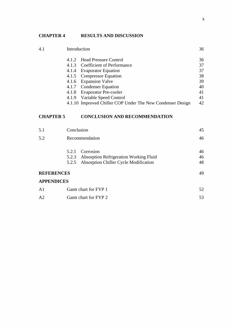
CHAPTER 4 RESULTS AND DISCUSSION
4.1 Introduction 36
4.1.2 Head Pressure Control 36
4.1.3 Coefficient of Performance 37
4.1.4 Evaporator Equation 37
4.1.5 Compressor Equation 38
4.1.6 Expansion Valve 39
4.1.7 Condenser Equation 40
4.1.8 Evaporator Pre-cooler 41
4.1.9 Variable Speed Control 41
4.1.10 Improved Chiller COP Under The New Condenser Design 42
CHAPTER 5 CONCLUSION AND RECOMMENDATION
5.1 Conclusion 45
5.2 Recommendation 46
5.2.1 Corrosion 46
5.2.3 Absorption Refrigeration Working Fluid 46
5.2.5 Absorption Chiller Cycle Modification 48
REFERENCES 49
APPENDICES
A1 Gantt chart for FYP 1 52
A2 Gantt chart for FYP 2 53

xi
LIST OF FIGURES
Figure No. Title Page
1.0 Efficiency of thermal driven chiller 2
1.1 Main components of an absorption chiller 3
2.0 Evaporator 10
2.1 Example of condenser 12
2.2 Types of compressors 16
2.3 Reciprocating compressor 17
2.4 Rotary screw compressor 19
2.5 Centrifugal compressor 20
2.6 Counter flow heat exchanger 21
2.7 Cross flow heat exchanger arrangement 22
3.0 Direct flow evacuated tube collector 30
3.1 Heat evacuated tube collector 31
3.2 Equation to determine COP 32
4.0 Graph COP against PLR 42
xii
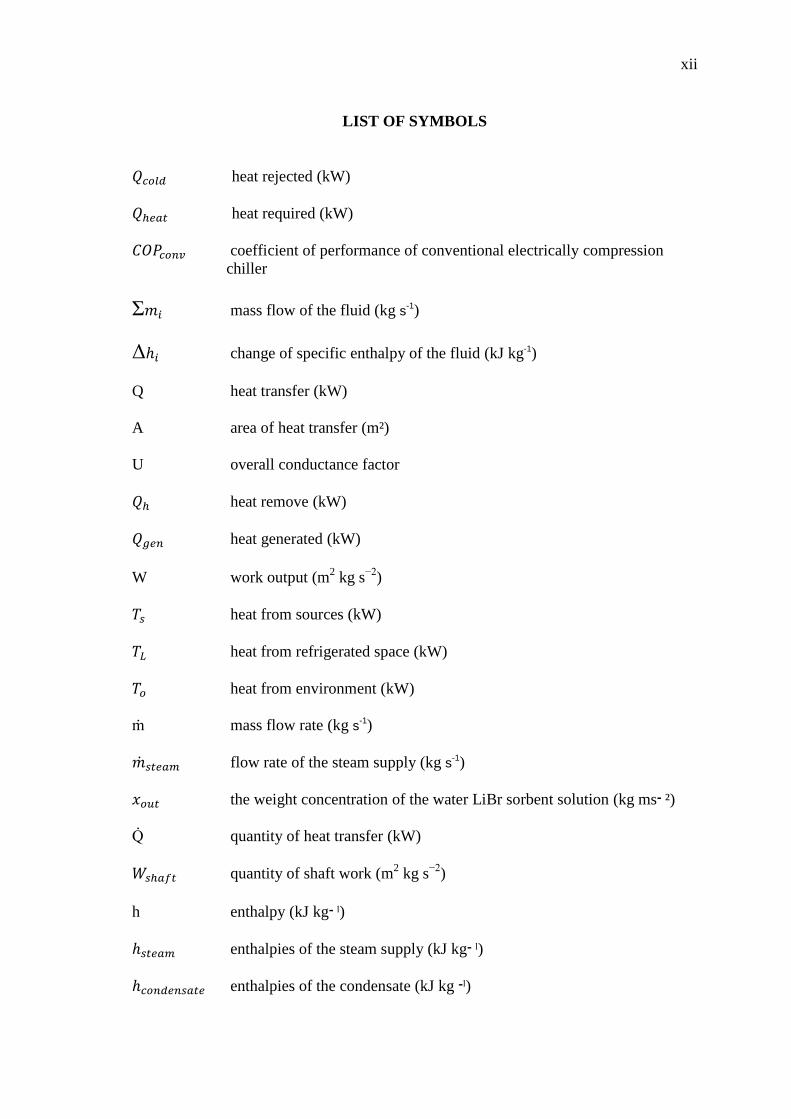
LIST OF SYMBOLS
heat rejected (kW)
heat required (kW)
coefficient of performance of conventional electrically compression
chiller
Ʃ mass flow of the fluid (kg s-1)
Δ change of specific enthalpy of the fluid (kJ kg-1)
Q heat transfer (kW)
A area of heat transfer (m²)
U overall conductance factor
heat remove (kW)
heat generated (kW)
W work output (m2 kg s
−2)
heat from sources (kW)
heat from refrigerated space (kW)
heat from environment (kW)
ṁ mass flow rate (kg s-1)
flow rate of the steam supply (kg s-1)
the weight concentration of the water LiBr sorbent solution (kg ms ־ ²)
quantity of heat transfer (kW)
quantity of shaft work (m2 kg s
−2)
h enthalpy (kJ kg ־ ˡ)
enthalpies of the steam supply (kJ kg ־ ˡ)
enthalpies of the condensate (kJ kg ־ˡ)

xiii
thermal energy (kW)
electrical energy (kW)
flow rate of chilled water (kg s ־ ˡ)
temperature of the chilled water entering the chiller (ºC)
temperature of the chilled water leaving the chiller (ºC)
specific heat of water (4.19 kJ kg ־ ˡ ºC ־ ˡ)
specific heat-capacity of air (1.02 kJ kg ־ ˡ ºC ־ ˡ)
cooling capacity (kW)
chilled power (kW)
compressor power (kW)
condenser fan power (kW)
chilled water flow (kg s ־ ˡ)
refrigerant mass flow/compressor (kg s ־ ˡ)
refrigerant effect (kJ kg ־ ˡ)
evaporating temperature (ºC)
heat-transfer coefficient of the evaporator (kW ºC)
volumetric displacement (m³ s ־ ˡ)
specific volume of superheated refrigerant (m³ kg ־ ˡ)
volumetric efficiency
isentropic efficiency
transmission efficiency
condensing temperature (ºC)
total mass-flow rate of the refrigerant (kg s ־ ˡ)
characteristic constant

xiv
density of the liquid refrigerant before expansion (kg m ־ ³)
pressure difference drop across the expansion valve (kPa)
heat rejection (kW)
A heat-transfer coefficient of the condenser (kW ºC ־ ˡ)
heat-rejection airflow (kW ºC ־ ˡ)
temperature of air entering the condenser (ºC)
temperature of air leaving the condenser (ºC)
LMTD log mean temperature different (ºC)
mass flow of the fluid (kg s ־ ˡ)
Δ change of specific enthalpy of the fluid (kJ kg ־ ˡ)
air density (1.2 kg m ־ ³)

xv
LIST OF ABBREVIATION
COP coefficient of performance
O water
N ammonia
O-N ammonia with water
kg kilogram
hr hour
U.S United State
Fig figure
BTU British Thermal Unit
TD temperature different
METD mean effective temperature difference
LiBr lithium bromide
HPC head pressure control
PLR part load ratio
CFC chlorofluorocarbon
MRI magnetic resonance imaging
kW kilowatt
1
CHAPTER 1
INTRODUCTION
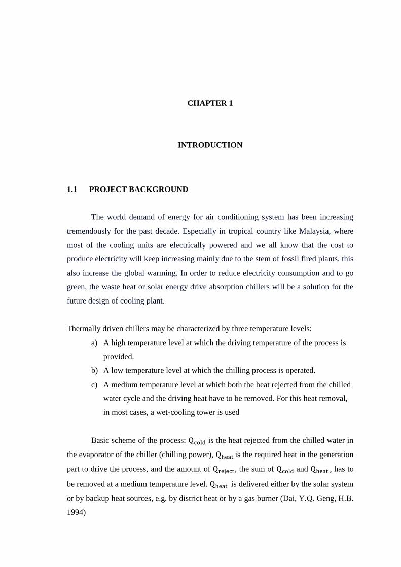
1.1 PROJECT BACKGROUND
The world demand of energy for air conditioning system has been increasing
tremendously for the past decade. Especially in tropical country like Malaysia, where
most of the cooling units are electrically powered and we all know that the cost to
produce electricity will keep increasing mainly due to the stem of fossil fired plants, this
also increase the global warming. In order to reduce electricity consumption and to go
green, the waste heat or solar energy drive absorption chillers will be a solution for the
future design of cooling plant.
Thermally driven chillers may be characterized by three temperature levels:
a) A high temperature level at which the driving temperature of the process is
provided.
b) A low temperature level at which the chilling process is operated.
c) A medium temperature level at which both the heat rejected from the chilled
water cycle and the driving heat have to be removed. For this heat removal,
in most cases, a wet-cooling tower is used
Basic scheme of the process: is the heat rejected from the chilled water in
the evaporator of the chiller (chilling power), is the required heat in the generation
part to drive the process, and the amount of , the sum of and , has to
be removed at a medium temperature level. is delivered either by the solar system
or by backup heat sources, e.g. by district heat or by a gas burner (Dai, Y.Q. Geng, H.B.
1994)
2
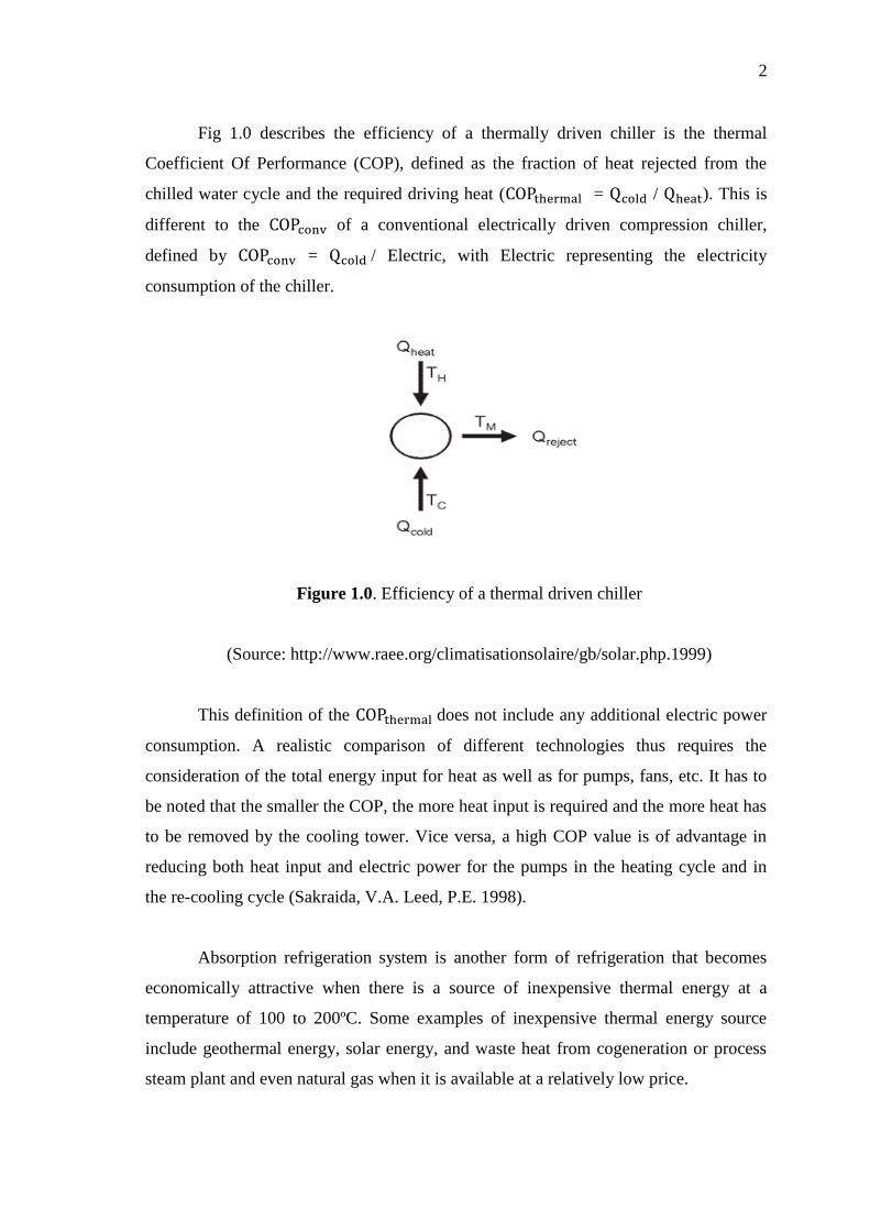
Fig 1.0 describes the efficiency of a thermally driven chiller is the thermal
Coefficient Of Performance (COP), defined as the fraction of heat rejected from the
chilled water cycle and the required driving heat ( = / ). This is
different to the of a conventional electrically driven compression chiller,
defined by = / Electric, with Electric representing the electricity
consumption of the chiller.
Figure 1.0. Efficiency of a thermal driven chiller
(Source: http://www.raee.org/climatisationsolaire/gb/solar.php.1999)
This definition of the does not include any additional electric power
consumption. A realistic comparison of different technologies thus requires the
consideration of the total energy input for heat as well as for pumps, fans, etc. It has to
be noted that the smaller the COP, the more heat input is required and the more heat has
to be removed by the cooling tower. Vice versa, a high COP value is of advantage in
reducing both heat input and electric power for the pumps in the heating cycle and in
the re-cooling cycle (Sakraida, V.A. Leed, P.E. 1998).
Absorption refrigeration system is another form of refrigeration that becomes
economically attractive when there is a source of inexpensive thermal energy at a
temperature of 100 to 200ºC. Some examples of inexpensive thermal energy source
include geothermal energy, solar energy, and waste heat from cogeneration or process
steam plant and even natural gas when it is available at a relatively low price.

3
As the name implies, absorption refrigeration system involve the absorption of a
refrigerant by a transport medium. The most widely used absorption refrigeration
system is the ammonia-water system, where ammonia serves as the refrigerant and
water as the transport medium. Other absorption refrigeration includes system water
lithium bromide and water lithium chloride system, where water serves as the
refrigerant. The latter two systems are limited to applications such as air conditioning
where the minimum temperature is above the freezing point of water.
Absorption chillers are the most distributed chillers worldwide. A thermal
compression of the refrigerant is achieved by using a liquid refrigerant or sorbent
solution and a heat source, thereby replacing the electric power consumption of a
mechanical compressor. For chilled water above 0°C, as it is used in air conditioning,
typically a liquid N / O solution is applied with water as refrigerant. Most systems
use an internal solution pump, but consuming little electric power only. In the operation
of an NH3/H2O absorption chiller, a crystallization of the solution has to be avoided by
an internal control of the heat rejection temperature in the machine. The main
components of an absorption chiller are shown in the Fig 1.1 (Boles, C. 2004).
Figure 1.1 Main components of an absorption chiller
(Source: http://www.raee.org/climatisationsolaire/gb/solar.php.1999)
4
The main components of an absorption chiller are the generator, the condenser,
the evaporator and the absorber. The cooling effect is based on the evaporation of the
refrigerant (water) in the evaporator at very low pressure. The vaporized refrigerant is
absorbed in the absorber, thereby diluting the N / O solution. To make the
absorption process efficient, the process has to be cooled. The solution is continuously
pumped into the generator, where the regeneration of the solution is achieved by
applying the driving heat such as from hot water supplied by a solar collector. The
refrigerant leaving the generator by this process condenses through the application of
cooling water in the condenser and circulates by means of an expansion valve again into
the evaporator.
1.2 PROBLEM STATEMENT
Using waste heat could be one of the largest conservation and green house gas
reduction opportunities. Heat recovery is an opportunity to recycle energy that is
typically wasted. That is why the absorption chiller is become more popular today in all
fields. By using absorption chillers, it can save electricity even when the overall COP
absorption chiller is low, but it can be overcomed by doing an analysis of all of
components in the system especially a condenser to get a better COP.
1.3 OBJECTIVES
The objectives of the project that need to be achieved are:
a) To study a system of absorption chiller
b) To understand the working process in every system that consists in absorption
chiller such as condenser, evaporator, compressor (generator and absorber) and
heat exchanger.
c) To calculate the COP of the absorption chiller

5
1.4 SCOPE
Design and development system of component of absorption thermally driver
chillers based on mathematical analysis on each corresponding component and the
behaviour of the circuit. Mathematical model analysis of corresponding component
(condenser, evaporator, absorber, and generator) is necessary.

6
CHAPTER 2
LITERATURE REVIEW
2.1 INTRODUCTION
This chapter contains a review of published information about the issues related
to this project. The operation of each component in this system such as evaporator,
condenser, compressor, heat exchanger and other related terms will also include in this
chapter. All of the information is gathered from books, journal and article. This
literature review not only attempts to collect and categorize previous research, but also
to attempts to analyze and evaluate previous works leading to this project’s framework.
2.2 CHILLERS
Chillers make things cool. Chillers generally refer to devices that cool fluids.
There are a wide variety of chillers, because there are many different fluids to cool
(including air), for a wide variety of uses. One common use for chillers is in cooling
buildings. Chillers will cool water, which is circulated through a building's cooling
system to keep things comfortable.
2.2.1 HOW CHILLER WORKS
Absorption chillers use low-grade waste heat to do the chilling. They lack the
motorized compressor used by other chillers types. Absorption chillers use a special
solution to absorb low-pressure refrigerant vapor, which is then sent to a high-pressure
generator where the refrigerant is desorbed and vaporized by the waste heat. The
refrigerant is then condensed to a high-pressure liquid, and passed through an expansion

7
valve and into an evaporator, which cools the evaporator. The vapors leave the
evaporator and go back to be recombined with the absorbent, and the process starts all
over again. Absorption chillers are useful in situations where waste heat (or a cheap
supply of fuel) is available, or where cost or other limitations prevent the use of a
mechanical compressor.
2.2.2 CHILLER USES
a) To convert waste heat from manufacturing processes for use in cooling.
b) Directing chilled air into gas turbines and compressors will increase their
efficiency
c) Chilled brine is used to create ice
d) Drinking water is often chilled before consumption
e) Chillers are essential to plasma etch processes used in semiconductor
manufacturing
f) High-intensity lasers create waste heat, and require special chillers to function
g) Chillers are used to cool objects being cut by machine tools
h) Chillers regulate temperature in reaction vessels used by the pharmaceutical
industry
I) MRI equipment requires careful thermal control to function, making chillers
necessary
2.3 ABSORPTION CHILLER
Absorption chillers use heat instead of mechanical energy to provide cooling. A
thermal compressor consists of an absorber, a generator, a pump, and a throttling
device, and replaces the mechanical vapor compressor. The two most common
refrigerant and absorbent mixtures used in absorption chillers are water/lithium bromide
and ammonia/water. Compared with mechanical chillers, absorption chillers have a low
coefficient of performance (COP = chiller load/heat input). However, absorption
chillers can reduce operating costs because they are powered by low-grade waste heat.
Vapor compression chillers, by contrast, must be motor or engine-driven.

8
A single-effect absorption machine means all condensing heat cools and
condenses in the condenser. From there it is released to the cooling water. A double-
effect machine adopts a higher heat efficiency of condensation and divides the generator
into a high-temperature and a low-temperature generator.
2.4 EVAPORATORS
Like the condenser, the evaporator is just a finned coil in the air-conditioning
system. Almost all are made of copper tubes with aluminium fins. The evaporator is the
cooling and dehumidifying coil in the air-conditioning circuit. It mentions this because
the typical residential/light-commercial air-conditioning system expends about a third of
its energy dehumidifying the air, with the other two-thirds just performing straight
(sensible) cooling. The major requirement in the field of evaporation technology is to
maintain the quality of the liquid during evaporation and to avoid damage to the
product. This may require the liquid to be exposed to the lowest possible boiling
temperature for the shortest period of time.
This and numerous other requirements and limitations have resulted in a wide
variation of designs available today. In almost all evaporators the heating medium is
steam, which heats a product on the other side of a heat transfer surface (Waltrich, P.J.
Jader, R. et al. 2002)
2.4.1 HISTORY OF EVAPORATORS
The evaporative cooler was design in the twentieth century. Starting in 1906. It
used excelsior (wood wool) pads as the elements to bring a large volume of water in
contact with moving air to allow evaporation to occur. A typical design, as shown in a
1945 patent, includes a water reservoir (with level controlled by a float valve), a pump
to circulate water over the excelsior pads, and a squirrel-cage fan to draw air through
the pads and into the house. This design and this material remain dominant in
evaporative coolers in the American Southwest, where they are also used to increase
humidity (Gutenberg, A.W. 1995)

9
There are three main measures of evaporator performance:
1. Capacity (kg vaporized / time)
2. Economy (kg vaporized / kg steam input)
3. Steam Consumption (kg / hr)
Economy calculations are determined using enthalpy balances. The key factor in
determining the economy of an evaporator is the number of effects. The economy of a
single effect evaporator is always less than 1.0. Multiple effect evaporators have higher
economy but lower capacity than single effect.
The thermal condition of the evaporator feed has an important impact on
economy and performance. If the feed is not already at its boiling point, heat effects
must be considered. If the feed is cold (below boiling) some of the heat going into the
evaporator must be used to raise the feed to boiling before evaporation can begin. This
reduces the capacity. If the feed is above the boiling point, some flash evaporation
occurs on entry (Chen, W. et al. 2002).
2.4.2 HOW AN EVAPORATOR WORKS.
From Fig 2.0 diluted process material (purple) is introduced into the tangential
feed inlets above the thermal body section. The material is then evenly distributed over
the internal wall of the evaporator by means of a distribution ring that is an integral part
of the evaporator rotor.
As gravity draws the process material downward into the heated thermal
sections, the rotor blades keep the material spread over the heated surface creating
effective film turbulence. This turbulence, which has been intentionally designed into
the evaporator, continually re-exposes all of the process material to the heated surface.
The continual rotation of process materials prevents localized over-heating and thus
helps to prevent the ―fouling‖ of the evaporator. Since the evaporator provides a
condition of high heat transfer and short residence time, rapid vaporization is attained.
At extremely low bottom output rates, an additional ring may be installed in the bottom
of the thermal section to increase residence time. This ring effectively acts as a dam,

10
causing the process flow to backup into the lower portion of the thermal sections
insuring proper process wetting in the heated vessel wall.
The resultant escaping vapours (blue) travel upward toward the vapour outlet,
being separated from the incoming feed by the distribution ring. Liquids, entrained in
the vapour steam, are trapped in the vapour section and drain back into the thermal
bodies. The ―liquid free‖ vapours pass through the vapour outlet ready to be condensed.
Meanwhile, the non-volatile processed product or residue (red) passes from the thermal
bodies to a bottoms cone and is discharged.
Figure 2.0 Evaporator
(Source: http://www.newtonmachine.com/evap-tof.htm.2007)
2.4.3 APPLICATION OF EVAPORATOR
The goal of evaporation is to concentrate a target liquid, and this needs to be
achieved for many different targets today. One of the most important applications of
evaporation is that on the food and drink industry. Many foods that are made to last for

11
a considerable amount of time or food that needs a certain consistency, like coffee, need
to go through an evaporation step during processing. It is also used as a drying process
and can be applied in this way to laboratories where preservation of long-term activity
or stabilization is needed (for enzymes as an example). Evaporation is also used in order
to recover expensive solvents such as hexane which would otherwise be wasted.
Another example of evaporation is in the recovery of sodium hydroxide in Kraft
pulping. Cutting down waste handling cost is another major application of evaporation
for large companies. Legally, all producers of waste must dispose of the waste in
methods that abides by environmental guidelines; these methods are costly. If up to
98% of wastes can be vaporized, industry can greatly reduce the amount of money that
would otherwise be allocated towards waste handling (Chen W. et al. 2002).
Typical evaporator applications
Product concentration
Dryer feed pre-concentration
Volume reduction
Water / solvent recovery
2.4.4 TYPE OF EVAPORATORS
Different Evaporation Systems
Falling Film Evaporators
Rising Film Evaporators
Forced Circulation Evaporators
Plate Evaporators
Compact Evaporators
2.5 CONDENSERS
Condensers are refrigeration devices that accept vaporized refrigerant from an
evaporator and then compress and liquefy it for use in the system. There are generally
two types of condensers, an air conditioning condenser and a refrigeration condenser.
An air conditioning condenser is used to convert hot and high pressure refrigerant gas to

12
a sub cooled liquid. A heat exchange condenser located in a refrigeration system is
known as a refrigeration condenser. Heating and cooling are the two main aspects of
how condensers function. Heat loss and heat gain are the processes by which heat can
be exchanged from the surroundings. Leaking and losing of heat at a specific low
temperature in the region is known as heat loss whereas the quantity of heat that needs
to be removed to maintain indoor comfort on a specific warm day is known as heat gain.
Central heating stands for heating of a region from a central source. Central air
conditioning is the process by which the region is cooled at the time of humid
temperatures (Qureshi, A.B. Zubair, S.M. 2006).
2.5.1 HOW A CONDENSER WORK
Condensers consist of a condenser coil, compressor, fan, and control. In an air
conditioning condenser the refrigerant is compressed and run through a series of tubes
to remove as much heat as possible as an illustrated at Fig 2.1. The refrigerant is then
piped to an evaporator coil as a warm liquid. Expansion of the compressed liquid causes
it to cool, and as the air passes over the coil, heat is extracted. The cool liquid becomes
a cool gas when it gathers heat from the air, and is drawn back to the compressor to start
the procedure again.
Figure 2.1 Example of Condenser
(Source: http://en.citizendium.org/wiki/Surface_condenser.2006)