the world of - m&y ventilation equipment ltdairhandlingunits.co.uk/my.pdf · the world of....
TRANSCRIPT

Standard and Special Air Handling Units for Ventilation and Air Conditioning Applications
The World of

Experience has shown that any attempt to produce a
catalogue covering a standard range of Air Handling
Units is not well received by our specifiers or
customers who can not see an end to the flexibility
they need when finding space for a large item of plant.
Catalogues in the main are used for reference only,
mainly to see what applications we can handle.This
catalogue is intended to give an overview of what can
be done with an indication of unit size. Our expertise
at M&Y is to produce special units that meet
individual specifications, configurations and sizes from
inside the catalogue keeping prices for special units
competitive.We will continue to discuss specific
requirements with our specifiers and customers.
Quotations and sketches will continue to be provided
against enquiries and we have a fast track same day
service for more urgent enquiries.A fast growing side
of our business especially in the greater London area
is site assembly of units in kit form.This gives the
designer freedom to use the latest generation
equipment for applications where lack of plantroom
access space would rule this out.
Standard & Special Air Handling Units for Ventilation & Air Conditioning Applications
page 2
INDEX• Introduction to the 2000 Range of Air Handling Units: .............................................................................................. page 2
• Selection Chart for the 2000 Range of Air Handling Units: ...................................................................................... page 8
• General Specification for the RFM Range of Recuperator Units: ............................................................................ page 12
• General Specification for the ECO Range of Recuperator Units: ............................................................................ page 14
• General Specification for the RKE Range of Recuperator Units: .............................................................................. page 16
• Selection Chart for the RKE Range of Recuperator Units: ........................................................................................ page 17
• Introduction to the LHCU Range of Low Height Ceiling Units:................................................................................ page 19
• Specification for the TF Range of Twin Fan Units: ........................................................................................................ page 20
• Selection Chart for Direct Driven Units: ........................................................................................................................ page 21
• Selection Chart for Belt Driven Units: ............................................................................................................................ page 21
INTRODUCTION TO THE 2000 RANGE OF AIR HANDLING UNITS

GENERAL
The "2000" range of Air Handling Units are basedupon a modular concept which provides and allowsindividual sections of varying lengths to be coupledtogether in various combinations to form completeunits.
All sections forming the Air Handling units are of aconsistent cross section, which with flush fitting panelsprovides a neat linear exterior along the length of theunits.The sections are suitable for horizontal orvertical installation as required. No additional supportsare required when sections are mounted on top ofeach other to form double deck units.
All units within the range are manufactured withdouble skin panels as standard, having either 25 or50mm insulation sandwiched between a plastisol outerskin and a galvanised steel inner skin. Triple skinpanels can be provided where noise breakout iscritical.
Framework can be constructed from eitherFully welded pentabox or extruded aluminiumdepending on the application.
The range consists of 19 standard sizes with a volumerange of 0.35 to 48.0 m3/s.With non-standard sizesavailable to suit space restrictions.
FRAMES - ALUMINIUM
The main frames are assembled from die castaluminium corner joints and extruded aluminiumprofiles, which offers a totally un-welded framework.The framework is a standard of double skin profile.According to the cross section size of the AHU theframework will be between 30 to 70 mm.The AHU casing has a strength of Class 2A with aThermal Transmittance Class T2 and ThermalThe framework and top hat sections are normallysupplied with a plain anodised finish.
FRAMES - WELDED
Section frames are constructed from 50mm pentaboxsection manufactured from galvanised sheet steel.Theframes are assembled using pre-formed cornersections, which are seam welded internally.Top hatsections are fitted between components, which arealso welded into position providing additional strengthand rigidity.
After assembly the full frames are de-greased, primedand finished with a high gloss paint.
PANELS
The panels are formed from heavy gauge hot dippedgalvanised steel sheet to BS2989 and are of the tray-in-tray construction.They are of varying heights andlengths dependent upon unit size and are designed toprevent drumming, distortion and vibration duringoperation.
All panels are removable with access doors hingedwith operated locks
All panels are double skinned with either 25 or 50 mmpanels for the aluminium range and 50mm for thewelded range.The fibreglass insulation incorporatedhas a density of 64 kg/m3 and a thermal conductivityof 0.04 W/m2 C.This insulation has excellent thermaland acoustic properties. It is also rot proof, odourless,non-hydroscopic and does not sustain vermin.Wherenoise breakout is critical perforated inner skins canalso be incorporated.
The inner skins will be formed from galvanised sheetsteel to BS2989, whereas the outer skin formed fromBSC Colorcoat HP200 Plastisol coating having ascratch resistance to BS3900, Part E2 and a colourrange to BS4904: 1978.
INTERNAL METALWORK
All internal framing and blanking plates aremanufactured from galvanised steel sheet to BS2989.
Standard & Special Air Handling Units for Ventilation & Air Conditioning Applications
page 3
FULL SPECIFICATIONS OF THE 2000 RANGE OF AIR HANDLING UNITS
Standard & Special Air Handling Units for Ventilation & Air Conditioning Applications
page 4
MILD STEEL CHANNEL BASES
Each section will be supplied bolted to a fully weldedbase frame, formed from 102 x 51 channel. For largerunits 150 x 78 mm channel will be used.The bases willbe painted to contrast the finish of the AHU frameworkor will be galvanised after manufacture for externallymounted AHU’s.
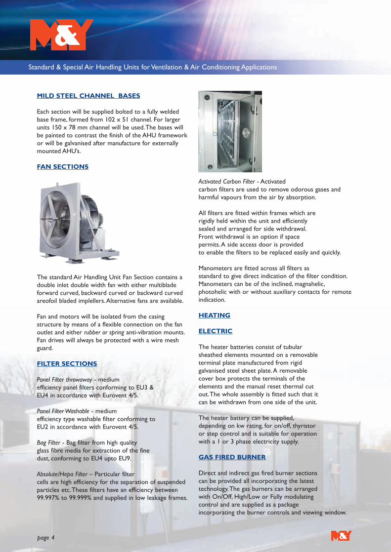
FAN SECTIONS
The standard Air Handling Unit Fan Section contains adouble inlet double width fan with either multibladeforward curved, backward curved or backward curvedareofoil bladed implellers.Alternative fans are available.
Fan and motors will be isolated from the casingstructure by means of a flexible connection on the fanoutlet and either rubber or spring anti-vibration mounts.Fan drives will always be protected with a wire meshguard.
FILTER SECTIONS
Panel Filter throwaway - medium efficiency panel filters conforming to EU3 & EU4 in accordance with Eurovent 4/5.
Panel Filter Washable - medium efficiency type washable filter conforming to EU2 in accordance with Eurovent 4/5.
Bag Filter - Bag filter from high quality glass fibre media for extraction of the fine dust, conforming to EU4 upto EU9.
Absolute/Hepa Filter – Particular filter cells are high efficiency for the separation of suspendedparticles etc.These filters have an efficiency between99.997% to 99.999% and supplied in low leakage frames.
Activated Carbon Filter - Activated carbon filters are used to remove odorous gases andharmful vapours from the air by absorption.
All filters are fitted within frames which arerigidly held within the unit and efficiently sealed and arranged for side withdrawal.Front withdrawal is an option if space permits.A side access door is provided to enable the filters to be replaced easily and quickly.
Manometers are fitted across all filters asstandard to give direct indication of the filter condition.Manometers can be of the inclined, magnahelic,photohelic with or without auxiliary contacts for remoteindication.
HEATING
ELECTRIC
The heater batteries consist of tubular sheathed elements mounted on a removable terminal plate manufactured from rigid galvanised steel sheet plate.A removable cover box protects the terminals of the elements and the manual reset thermal cutout.The whole assembly is fitted such that it can be withdrawn from one side of the unit.
The heater battery can be supplied,depending on kw rating, for on/off, thyristor or step control and is suitable for operation with a 1 or 3 phase electricity supply.
GAS FIRED BURNER
Direct and indirect gas fired burner sections can be provided all incorporating the latest technology.The gas burners can be arranged with On/Off, High/Low or Fully modulating control and are supplied as a package incorporating the burner controls and viewing window.

Standard & Special Air Handling Units for Ventilation & Air Conditioning Applications
page 5
LPHW - HPHW - STEAM COILS
All coils are constructed from seamless copper tubes and headers with continues plate type aluminium fins.Tubes are mechanically expanded into the fins to form a permanent bond for maximum heat transfer.
Casings are formed from galvanised steel sheet anddesigned for easy assembly. End plates are fitted toensure no bypass of airflow.
COOLING COILS
Cooling coils are constructed as per the heating coils. Positive drain trays are provided as standard under cooling coils and the design of the tray which would have a minimum slope of 1 in 20 towards the drain,ensuring that water retention is not possible.
Drain trays can be removable to provide full cleaning and disinfecting to control the growth of organisms as Legionella Pneumophila.All water coils are tested between 300 PSI and 450 PSIG whereas DX coils are dehydrated under vacuum and charged withnitrogen before sealing.
Both Heating & Cooling Coils will be supplied with non-ferrous heavy duty terminals having a BSP (M) thread.
Coils can be provided with either:
• Bare tubes - no fins
• Copper fins
• Vynal coated fins
• Electro tinned copper tubes
• Stainless steel casings
• Steel tubes & fins
ELIMINATORS
Eliminator plates if required will be of the Multiple blade configuration and corrosion Resistant.The blades will be manufactured From either PVC or Polypropylene to provide an inert, non-combustible, corrosionresistant and vermin proof assembly.
HEAT RECOVERY
HEAT RECOVERY COILS
This a heat recovery system using a coil installed in the exhaust air ducts to recover heat energy, transferring this energy to the heating coils in the Air Handling Units.A closed circuit system links the two sets of coils using as a medium water of glycolsolution and the system is completed with expansion vessel, pumps, etc.
AIR TO AIR RECUPERATOR
Two ranges are available depending on the space limitations and can be supplied in either crossflow or diagonal flow. Both types incorporate a number of aluminium heat transfer plates held in galvanised steel framework.
The two airstreams are completely separated by the construction of the unit thereby ensuring no cross-contamination.Face and by-pass dampers suitable for either manual or motorised control can also be provided.A drain tray would be fitted on the exhaust air leaving face to drain away any condensation that may occur.

Standard & Special Air Handling Units for Ventilation & Air Conditioning Applications
page 6
THERMAL WHEELS
The heat wheel is an air to air rotary heat exchanger, which recovers heat energy from the exhaust air to gases and transfers the energy to the counter flowing fresh air airstream.A range of heat wheels are available to transferboth sensible and latent heat.Variable speed and constantspeed drives for the wheel are available dependent uponapplication.
Alternative methods of heat/transfer available:
Desiccant wheelAdiabatic coolingHeat pipes
STEAM HUMIDIFIERS
SELF GENERATIVE TYPE
The self generative humidifier produces steam by means of electrodes or resistance type heating elements producing steam at atmospheric pressure which is injected into the airstream via injection lances.
A cabinet is supplied containing the steam boiler and electrical controls in separate compartments.A water supply, electrical supply and drainage will be required for the humidifier.
DIRECT STEAM INJECTION TYPE
Direct steam injection humidifier inject dry steam into the airflow within the Air Handling Unit details of injection ducts and space requirements are as described above.A steam supply and drainage will be required for thehumidifier. Control valves and actuators of theelectric/electronic or pneumatic type can also besupplied.
INTAKE/MIXING DAMPERS
Dampers will be of the opposed blade type.The blades are interconnected to give positive action without flutter.The edges of the individual blades are fitted with seals ensuring a tight seal. Dampers are suitable for either manual or automatic control.
EXTERNALLY MOUNTED UNITS
Units will be supplied with a weather canopy to shed thewater.All non access panels will be sealed with siliconeto prevent the ingress of water.Were requiredintake/discharge louvres will be fitted. In addition channelbase frames will be galvanised after manufacture andpainted to match the colour of the AHU.
ADDITIONS TO STANDARD SPECIFICATIONFOR COASTAL APPLICATIONS
UNIT FRAMEWORK
Unit framework to be of fully welded construction.Paint internally and externally with anti corrosionaquabond paint finish.
PANELS
50mm deep (standard)Inner Plastisol.Outer Plastisol. (standard)
FANS
Chlorinated rubber / epoxy finish by manufacturer.
SUB-FRAME
Hot dipped galvanised after manufacturer.
HEATING/COOLING COILS
Copper tubes/Aluminium fins – Epoxy (or similar)coated.

Standard & Special Air Handling Units for Ventilation & Air Conditioning Applications
page 7
PLATE HEAT EXCHANGERS
Aluminium Acrylic paint.Corrosion protected casing.
MOTORS
Anti corrosion paint finish.
DRAIN TRAYS
304 Stainless steel.
ADDITIONS TO STANDARD SPECIFICATIONFOR SWIMMING POOL APPLICATIONS
UNIT FRAMEWORK
Unit framework to be of fully welded construction.Paint internally and externally.
PANELS
50mm deep (nominal)Inner PlastisolOuter Plastisol
FANS
Chlorinated rubber / epoxy finish by manufacturer.
SUB-FRAME
Hot dipped galvanised after manufacture.
HEATING/COOLING COILS
Copper tubes/Aluminium finish – Epoxy (or similar)coated
PLATE HEAT EXCHANGERS
Aluminium Acrylic painted.
MOTORS
Chlorinated rubber finish.Anti-condensation heaters.Thermistors.
DRAIN TRAYS
304 Stainless steel.
OPTIONAL ITEMS
• Externally mounted motors.• Run and standby motors.• Fan motors pre-wired to externally mounted isolators.• Kit form and site assembly.• Swimming pool applications.• Coastal applications• HTM 2025 / CO4 Specification AHU’s.• Volumetric test to BS 6583:1985.• DW 143 leakage test.• Viewing windows.• Plug fans • Bulk head lights pre-wired to externally mounted
switches.• Test points.• Fitting of “free issue” controls.• Lockable access doors.• Downpipes and gutters.• Traffolyte labels.• Centrifugal direct drive or motorised impellors fans.• Frequency invertors.• Removable drain trays• Individual customer specification.
Standard & Special Air Handling Units for Ventilation & Air Conditioning Applications
page 8
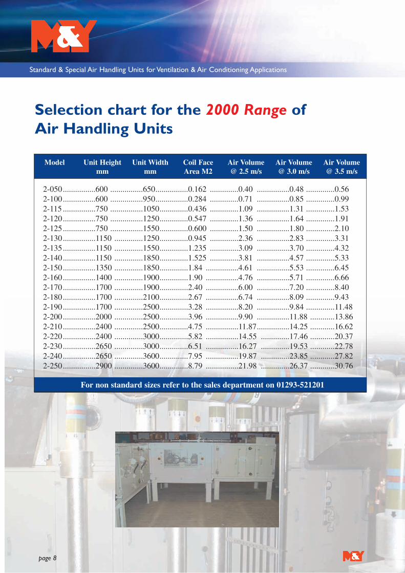
Selection chart for the 2000 Range of Air Handling Units
2-050................600 ................650................0.162 ..............0.40 ................0.48 ..............0.562-100................600 ................950................0.284 ..............0.71 ................0.85 ..............0.992-115 ................750 ................1050..............0.436 ..............1.09 ................1.31 ..............1.532-120................750 ................1250..............0.547 ..............1.36 ................1.64 ..............1.912-125................750 ................1550..............0.600 ..............1.50 ................1.80 ..............2.102-130................1150 ..............1250..............0.945 ..............2.36 ................2.83 ..............3.312-135................1150 ..............1550..............1.235 ..............3.09 ................3.70 ..............4.322-140................1150 ..............1850..............1.525 ..............3.81 ................4.57 ..............5.332-150................1350 ..............1850..............1.84 ................4.61 ................5.53 ..............6.452-160................1400 ..............1900..............1.90 ................4.76 ................5.71 ..............6.662-170................1700 ..............1900..............2.40 ................6.00 ................7.20 ..............8.402-180................1700 ..............2100..............2.67 ................6.74 ................8.09 ..............9.432-190................1700 ..............2500..............3.28 ................8.20 ................9.84 ..............11.482-200................2000 ..............2500..............3.96 ................9.90 ................11.88 ............13.862-210................2400 ..............2500..............4.75 ................11.87................14.25 ............16.622-220................2400 ..............3000..............5.82 ................14.55 ..............17.46 ............20.372-230................2650 ..............3000..............6.51 ................16.27 ..............19.53 ............22.782-240................2650 ..............3600..............7.95 ................19.87 ..............23.85 ............27.822-250................2900 ..............3600..............8.79 ................21.98 ..............26.37 ............30.76
For non standard sizes refer to the sales department on 01293-521201
Model Unit Heightmm
Unit Widthmm
Coil FaceArea M2
Air Volume@ 2.5 m/s
Air Volume@ 3.0 m/s
Air Volume@ 3.5 m/s

Standard & Special Air Handling Units for Ventilation & Air Conditioning Applications
page 9
2-050..........600 ............650............110 ..........190..............310 ..........180 ............430 ............6902-100..........600 ............950............110 ..........190..............320 ..........180 ............430 ............6902-115 ..........750 ............1050..........110 ..........190..............410 ..........180 ............430 ............6902-120..........750 ............1250..........110 ..........190..............420 ..........180 ............430 ............6902-125..........750 ............1550..........110 ..........190..............420 ..........180 ............430 ............6902-130..........1150 ..........1250..........110 ..........190..............640 ..........180 ............430 ............6902-135..........1150 ..........1550..........110 ..........190..............660 ..........180 ............430 ............6902-140..........1150 ..........1850..........110 ..........190..............680 ..........180 ............430 ............6902-150..........1350 ..........1850..........110 ..........210..............860 ..........200 ............450 ............7102-160..........1400 ..........1900..........110 ..........210..............860 ..........200 ............450 ............7102-170..........1700 ..........1900..........110 ..........210..............1050 ........200 ............450 ............7102-180..........1700 ..........2100..........110 ..........210..............1050 ........200 ............450 ............7102-190..........1700 ..........2500..........110 ..........210..............1070 ........200 ............450 ............7102-200..........2000 ..........2500..........150 ..........250..............1250 ........200 ............450 ............7102-210..........2400 ..........2500..........150 ..........250..............1470 ........200 ............450 ............7102-220..........2400 ..........3000..........150 ..........250..............1500 ........200 ............450 ............7102-230..........2650 ..........3000..........150 ..........250..............1650 ........200 ............450 ............7102-240..........2650 ..........3600..........150 ..........250..............1670 ........200 ............450 ............7102-250..........2900 ..........3600..........150 ..........250..............1825 ........200 ............450 ............710
ALL DIMENSIONS ARE IN MILLIMETRES
Unit RefP
Unit Height
Unit Width
Externaldamper
Internaldamper
Mixingbox
PanelFilter
Bag350 long
Bag610 long
A B C D E F
Selection chart for the 2000 Range of Air Handling Units

Standard & Special Air Handling Units for Ventilation & Air Conditioning Applications
page 10
Unit RefP
Hepa filter
Access350mm
Access600mm
1 to 3rowcoil
4 to 8row coil
Eliminator Electricheater
G H I J K L M
Selection chart for the 2000 Range of Air Handling Units
2-050 ............1200 ............430 ..............680 ..............280 ..............430................230 ..............3802-100 ............1200 ............430 ..............680 ..............280 ..............430................230 ..............3802-115 ............1200 ............430 ..............680 ..............280 ..............430................230 ..............3802-120 ............1200 ............430 ..............680 ..............280 ..............430................230 ..............3802-125 ............1200 ............430 ..............680 ..............280 ..............430................230 ..............3802-130 ............1200 ............430 ..............680 ..............280 ..............430................230 ..............3802-135 ............1200 ............430 ..............680 ..............280 ..............430................230 ..............3802-140 ............1200 ............430 ..............680 ..............280 ..............430................230 ..............3802-150 ............1200 ............450 ..............700 ..............300 ..............450................250 ..............4002-160 ............1200 ............450 ..............700 ..............300 ..............450................250 ..............4002-170 ............1200 ............450 ..............700 ..............300 ..............450................250 ..............4002-180 ............1200 ............450 ..............700 ..............300 ..............450................250 ..............4002-190 ............1200 ............450 ..............700 ..............300 ..............450................250 ..............4002-200 ............1200 ............450 ..............700 ..............300 ..............450................250 ..............4002-210 ............1200 ............450 ..............700 ..............300 ..............450................250 ..............4002-220 ............1200 ............450 ..............700 ..............300 ..............450................250 ..............4002-230 ............1200 ............450 ..............700 ..............300 ..............450................250 ..............4002-240 ............1200 ............450 ..............700 ..............300 ..............450................250 ..............4002-250 ............1200 ............450 ..............700 ..............300 ..............450................250 ..............400
ALL DIMENSIONS ARE IN MILLIMETRES

Standard & Special Air Handling Units for Ventilation & Air Conditioning Applications
page 11
2-050............1600 ..............1500 ............ 900..............580 ............ 800..............50 ..................752-100............1600 ..............1500 ............ 900..............580 ............ 900..............50 ..................752-115............1600 ..............1500 ............1100..............580 ............1000..............50 ..................752-120............1600 ..............1500 ............1100..............580 ............1200..............50 ..................752-125............1600 ..............1500 ............1500..............580 ............1500..............75 ..................1002-130............1600 ..............1500 ............1500..............580 ............1500..............75 ..................1002-135............1600 ..............1500 ............1500..............580 ............1500..............75 ..................1002-140............1600 ..............1500 ............1900..............580 ............1500..............100 ................1002-150............1600 ..............1700 ............1900..............600 ............1800..............100 ................1002-160............1600 ..............1700 ............1900..............600 ............1800..............100 ................1002-170............1600 ..............1700 ............1900..............600 ............1800..............100 ................1002-180............1600 ..............1700 ............1900..............600 ............1800..............100 ................1002-190............1600 ..............1700 ............2100..............600 ............2000..............100 ................1002-200............1600 ..............1700 ............2100..............600 ............2000..............100 ................1002-210............1600 ..............1700 ............2100..............600 ............2000..............100 ................1002-220............1600 ..............1700 ............2600..............600 ............2500..............150 ................1502-230............1600 ..............1700 ............2600..............600 ............2500..............150 ................1502-240............1600 ..............1700 ............2600..............600 ............2700..............150 ................1502-250............1600 ..............1700 ............2600..............600 ............2700..............150 ................150
ALL DIMENSIONS ARE IN MILLIMETRES
O P Q R S
Selection chart for the 2000 Range of Air Handling Units
Unit RefP
Humidifier Indirect gas fired burner
Fan Thermal wheel
Recuperator Weathercanopy
Base frame

Standard & Special Air Handling Units for Ventilation & Air Conditioning Applications
page 12
General Specification for the RFM Range ofRecuperator UnitsGENERAL SPECIFICATION
The New Automatic RFM heat recovery units are available in both P and T versions in 5 different sizes, with a nominalair capacity ranging from 900 m3/h to 3300 m3/h.The units have been developed to satisfy four typical needs ofresidential and commercial applications.
1.The renewal of room air, particularly needed for building where smoking is allowed.2.The energy saving, by using a static crossflow heat exchanger.3.The neutralisation of the renewal air heat loads by a fully automatic microprocessor controlled heat pump system; in
particular, the function of heat recovery increases both cooling and heating performances.4.The neutralisation of room heat loads, specifically for P version, where the available power left over the renewal air
heat loads is particularly high; the T version, because of a lower room available power, has to be generally intergratedby other heating/cooling systems.
GENERAL CONSTRUCTION AND TECHNICAL FEATURES
• Aluzink frame• Fully removable double skin Aluzink panels, with polyethylene or polyester thermal and acoustic insulation having a
minimum thickness of 20mm.• High efficiency crossflow heat recovery, aluminium heat exchanger plates with supplementary sealing, stainless steel
drain tray, extended to all cooling/heating components and heat insulated.• G3 efficiency synthetic cell filters, positioned on suction sections and easily removable from the side or bottom.• Single speed double inlet forward curved fans, matched with an electronic speed regulator or supplied with a built-in
frequency invertor motor. Fans are mounted on rubber anti-vibration mounts.• Heat pump refrigeration system (R407C) comprises a scroll hermetic compressor, 3 row summer evaporator/winter
condenser coil and a 7 row summer condenser/winter evaporator coil, constructed from copper tubes withaluminium fins, bi-directional thermostatic valve, liquid separator, receiver, 4-way valve for cycle inversion, safety valve,high and low pressure switches, freon filter and liquid indicator.
• Internal electrical board for supplying all the electrical powers; room outside and frost temperature sensors;microprocessor control, for fully automatic management of room temperature, free-cooling and free-heating,heating/cooling mode and defrost cycles; display for setting and for visualizing sensor and set point temperaturevalues, connected up to 20 metres from the unit board.
• T Version Units have a single pass recuperator whereas P Version Units have in addition to the recuperator, a fixedreturn air damper set at 50% of the volume, thus increasing the amount of heat or cool air recovered.
UNIT LAYOUT AND DIMENSIONS
ACCESSORIES
Model RFM 14 RFM 19 RFM 25 RFM 30 RFM 40
A mm 1450 1450 1700 1700 1700B mm 1230 1230 1560 1560 1560C mm 470 470 530 530 630L mm 240 240 306 339 339H mm 270 270 270 297 297L1 mm 337 337 502 502 502H1 mm 327 327 347 387 487Weight 225 225 247 258 279

Standard & Special Air Handling Units for Ventilation & Air Conditioning Applications
page 13
General Specification for the RFM Range ofRecuperator Units (continued)
The RFM units can be supplied with a complete series of accessories, selected for facilitating the installation, flowadjusting and safety; they are:
• Additional electric heating• Adiabatic humidifier/cooler• Cutting phase speed controller• Built-in frequency invertor• Air filter pressure switch• Intake dampers• Anti-vibration duct joining kits• Weather canopy.
ELECTRONIC CONTROLLER
The electronic control system inside the RFM units comprises of two parts, the console and the power board, eachconnected to the other through a common telephonic cable.The console, should be installed in an easily accessibleplace, which lets the User input the control parameters by the front keyboard. On the display each operation isvisualised and confirmed; the power section, installed inside the electrical board, is an electronic component thatcontrols the electrical outlets on the base of the parameters and the configuration determined by the User.
On the console, there are:• The Keyboard, for setting the working parameters.• The Display, for visualising the set values, room temperature and system alarm codes.• The Signalling LEDS, for visualising system working mode (on-off, cooling, heating, free-cooling, defrost and alarm).
Mute alarm
Standard & Special Air Handling Units for Ventilation & Air Conditioning Applications
page 14
GENERAL SPECIFICATION
The New Eco Range of Adiabatic Air Handling Units are manufactured bespoke to suit individual clients requirements.The Eco Range optimises the hidden energy both directly and indirectly via a heat recovery unit between the supplyand extract air streams.The overall C.O.P is further improved by placing the mechanical refrigeration condenser withinthe extract air stream after the adiabatic indirect cooling operation, which provides lower air on temperatures, hence,lower condensing pressures.
BENEFITS OF THE ECO RANGE:
• Reduced running costs due to lower condensing temperatures and all year round Free Cooling concept, provides reliable and lower annual electric running costs.
• Quick Response as water is introduced via a heat recovery unit, which provides a large evaporation surface, andinline mechanical refrigeration effectively responds to any load changes.
• Flexible systems as the combination of refrigeration, direct and indirect adiabatic cooling systems suit both dry desertas well as high humidity tropical conditions.
• Green solution due to the smaller refrigeration machinery together with less electricity consumption reducesenvironmental impact significantly.
• Improved indoor air quality as the combination of full fresh air and adiabatic cooling improves indoor air quality.• Lower maintenance as the lower condensing temperatures together with full outside air and adiabatic cooling
process minimise the mechanical refrigeration running hours.• Reduced water consumption as water is used whenever is required at significantly reduced volume.
TECHNICAL FEATURES
1.A high efficiency extract fan provides not only extract from the space, but the same air stream is utilised for the heatrejection coil airflow.
2. High efficiency panel filters ensure clean air for full fresh air operation all year round.Aninclined gauge manometerwill be fitted across each filter bank.
3.The control panel ensures that the unit requires only power supply and room thermostat on/off and temperatureinput.The rest of the controls and all the necessary safety features are incorporated for a fully automated coolingand heating operation all year round.
4.The direct spray nozzles operate if the outside humidity is less than an adjustable pre-set value, the direct spray nozzles are activated in order to provide free cooling.As soon as humidity exceeds the level the nozzles are isolated.
5.The indirect spray nozzles are positioned within the return air stream and the combination of heat recovery andindirect adiabatic cooling effect is transferred to the incoming air stream without increasing the humidity.Wet coolerair is further used for the condenser air flow which is considerably lower than the ambient, hence, considerableenergy saving.
6.The compressor is a high efficiency reciprocating/scroll type, which provides both heating and cooling as a heat pumpsystem.
7.The high efficiency supply fan provides full fresh airflow for the space.8.The coils within the Eco Range operate depending on the outside air temperature.The coil will provide either
heating or cooling to the supply air.The extract air acts as a condenser during winter mode for all year roundoperation.
General Specification for the ECO Range ofRecuperator Units
Standard & Special Air Handling Units for Ventilation & Air Conditioning Applications
page 15
OPTIONAL FEATURES
• 25mm thick or 50mm thick panels.• Plastisol or pre-painted outer skins.• Direct driven or belt driven fans.• Internal or external mounting.• Coils constructed from either copper tubes/aluminium fins, copper tubes/ acrylic coated aluminium fins, copper
tubes/copper fins or copper tubes/cooper fins all electro-tinned.• Filtration from G3 to G8 or combination of both.• Single or double pass recuperators.• Viewing windows, bulk head lights, test points• Stainless steel drain trays.• Test points.• Lockable access doors.
General Specification for the ECO Range ofRecuperator Units (continued)

Standard & Special Air Handling Units for Ventilation & Air Conditioning Applications
page 16
GENERAL SPECIFICATIONS
The RKE series heat recovery units are available in 7 different models, with a nominal air capacity ranging from 290m3/h to 3200 m3/h.They have been designed specifically to solve the problem of the excessive energy consumption ofall industrial plants operating with the use of external air. It is possible, due to the high efficiency of the plate heatexchanger, to recuperate over 50 % of the energy that would normally be lost.
The RKE units may be integrated with traditional systems, comprising of fans, air conditioners and radiators.This allowsthe possibility to utilize the apparatus both in the summer and winter seasons.The RKE units are particularly suitablefor false ceiling installation, and may be suitably ducted to allow air delivery and suction directly into the area.
UNIT CONSTRUCTION
• The unit casing is fabricated from single or double skin panels.• Each unit has polyethylene and polyester thermal and acoustic insulation.• The thickness of the insulation changes depending on the model.• The panels are fixed to the structure with cadmium plated steel screws.• All the internal components are easily accessible for inspection.• When necessary, internal components are easily replaceable from below.
FAN
The fan section is fitted with a forward curved centrifugal fan (single inlet for the 03 model, double inlet for the rest ofthe range), it is mounted on anti vibration mounts, allowing the unit to operate at the maximum speed with lowestpossible noise level.The electric motor, directly coupled with the fan, is a 230V / 50Hz single phase type, with one ormore speed settings that may be regulated from the control panel.
HEAT RECOVERY
The heat recuperator is a high efficiency static type, with cross airflow.The heat exchanger plates are made of aluminium, and the airflow is kept separate by the utilization of special seals.The heat recuperator is dimensioned in such a way to enable a high degree of thermal efficiency in any condition.Underneath the recuperator, a stainless steel condensation collection tray with a circular drainage pipe is positioned.
AIR FILTER
The filters are of the flat cell corrugated type, with class G3 synthetic fibre filtering material (efficiency 85% - EU3),which can be easily removed and replaced.
ACCESSORIES
SKW Hot water coilSKE Electric heaterSKR Regulation damperCVU Speed ControlPCU Control Panel
General Specification for the RKE Range ofRecuperator Units

Standard & Special Air Handling Units for Ventilation & Air Conditioning Applications
page 17
Model (dimensions in mm) 03 06 10 14 19 25 30
A ....................................................990........990 ........1150 ......1350 ......1450 ........1700 ........1700B ....................................................750........750 ........860 ........900 ........900 ..........1230 ........1230C ....................................................270........270 ........385 ........410 ........470 ..........490 ..........530D ....................................................130........230 ........240 ........240 ........240 ..........310 ..........340E ....................................................110........105 ........220 ........270 ........270 ..........270 ..........300
Selection data for the RKE Range of Recuperator Units (continued)
TECHNICAL DATA
Model 03 06 10 14 19 25 30
Air delivery .............. m3/h ..........290........600 ........1000 ......1400 ......1900 ........2500 ........3200Static pressure ..........Pa................40..........80 ..........90 ..........140 ........120 ..........110 ..........170Sound pressure ..........dB (A) ........54..........56 ..........54 ..........59,5........58 ............ 57,5 ........60
Fans
Shaft power ..............W ................2x45......2x90 ......2x147 ....2x350 ....2x350 ......2x350 ......2x550Poles ..........................n° ................4............2 ............4 ............4 ............4 ..............4 .............. 4 F.L.C. max.................A ................1,3 ........1,8..........3 ............5,8..........6,2............6 ..............11,4No. of fan speeds ......n° ................2............1 ............3 ............3 ............3 ..............3 ..............3 Protection grade ........IP ................20..........54 ..........44 ..........55 ..........44 ............55 ............20Isolation grade ..............................B ..........F ............F ............F ............F ..............F ..............FElectric power supply ..V ................230........230 ........230 ........230 ........230 ..........230 ..........230
Heat recovery (*)
Efficiency ..................% ................52,3 ......54,6........53,4........52,1........51,8..........57,6 ..........56Thermal power ..........kW ..............1,34 ......2,57........4,6..........6,2..........8,4............12,3 ..........15,3Output air temp. ........°C................8,1 ........8,7..........8,3..........8,0..........7,9............9,4 ............9,0
(*) Performances under following conditions: output air 20° - fresh air –5°
DIMENSIONS

Standard & Special Air Handling Units for Ventilation & Air Conditioning Applications
page 18
TECHNICAL DATA
Selection data for the RKE Range of Recuperator Units (continued)
Heating water coil (**)
Unit code ............................................SKW 10/3 ....SKW 14/3......SKW 19/3 ......SKW 25/3 ......SKW 30/3
Rows (N°)............................................3....................3 ....................3 ....................3 ....................3Heating capacity (kW) ........................9.4 ................13.4................16.6 ................23.9 ................28.4Air output temp. (°C) ..........................36..................36 ..................34 ..................36 ..................34Air side pressure drop (Pa)..................65..................64 ..................85 ..................62 ..................85Water side pressure drop (KPa) ..........8....................16 ..................10 ..................11 ..................15
(**) Performances under following conditions: water 70/60 °C - Ting. air= 8 °C - air nominal delivery
Electric HeatingUnit code ..........................................SKE 03 ....SKE 06....SKE 10 ....SKE 14 .....SKE 19 ....SKE 25 ..SKE 30
Electrical resistance 1 stage (kW)....2 ..............4 ..............4,5 ............6................9 ...............12 ............12Electrical supply (V) ........................230 ..........230 ..........400 ..........400............400 ...........400 ..........400
EXTERNAL INTERNAL
Type A
Return air
Supply air
Fresh air
Exhaust air
Type B
EXTERNAL INTERNAL
Return air
Supply air
Fresh air
Exhaust air
EXTERNAL
INTERNAL
Return airSupply air
Fresh airExhaust air
Type D
EXTERNAL
INTERNAL
Return airSupply air
Fresh airExhaust airType C

Standard & Special Air Handling Units for Ventilation & Air Conditioning Applications
page 19
Introduction to the LHCU Range of Low Height Ceiling Units
SPECIFICATIONS
The range of Low Height Ceiling Units have been designed where space is at a premium.The low height of 380mmmakes the units especially suited for mounting inside suspended ceilings.
Panels will be double skinned as standard with high-density insulation thus reducing the amount of noise breakout.The inner skins will be formed from galvanised sheet steel with the outer skins from pre-painted steel
Depending on the volume and external resistance the fans will be either direct driven or belt driven. Both options willhave forward curved impellors. Fan casings will be formed from high quality galvanised sheet steel and will be staticallyand dynamically balanced.To avoid transmission of vibration to the unit casing, the fan and motor assembly will bemounted on rubber anti vibration mounts and the fan discharge connection will have a fire retardant flexibleconnection.
Fan motors will be pre-wired to externally mounted terminal boxes or isolators.
Access for maintenance is from the underside to the fan and filter sections with either hinged or lift off panels to suitthe location.
All standard components can be incorporated including heating and cooling coils, attenuators, panel filters, bag filters,dampers and recuperators.
Unit Ref COIL FACE VELOCITY (m/s)
1.50 2.00 2.50 3.00 3.50 4.00
AIR VOLUME (m3/s)
LHCU 1 0.18 0.25 0.30 0.36 0.42 0.48LHCU 2 0.29 0.39 0.49 0.58 0.68 0.78LHCU 3 0.41 0.54 0.68 0.81 0.95 1.08
Unit Ref UNIT DATA
Height Width Max Motor Power kW FLC Amps STC Amps
LHCU 1 380 710 2.20 5.00 26.00LHCU 2 380 1040 2.20 5.00 26.00LHCU 3 380 1370 2.20 5.00 26.00
Non-standard variations of the units can be designed to suit individual applications with units up to 2600mm wideor 350mm high.

Standard & Special Air Handling Units for Ventilation & Air Conditioning Applications
page 20
Twin Fan Extract Units
• TFD – Direct drive twin fan extract units.• TFB – Belt driven twin fan extract units.
The TF range of twin fan units have been designed to provide the ultimate in simple box design. Constructed fromeither galvanised steel or aluminium with access via a removable top panel. Duct connections can be of the circular orrectangular spigot type.
• Two DIDW forward curved centrifugal fans for run and standby operation.• Non-return flaps fitted to prevent recirculation.• Both fans are pre-wired to externally mounted terminal boxes.
All units can be provided with the following options:
• Single skin construction with acoustic lined casings.• Aluminium construction.• Bolt on silencers.• Auto changeover panels with either manual / or automatic duty share.• Airflow switches.• Discharge louvers/cowls.• Speed controllers
The units have a volume range of 0.05M3/s to 2.50M3/s utilising either direct driven or belt driven fans.
For volumes above 2.50M3/s pentapost framed units can be provided with double skin or triple skin panels.
Specification for the TF Range of Twin Fan Units

Standard & Special Air Handling Units for Ventilation & Air Conditioning Applications
page 21
Sel
ecti
on
Cha
rt f
or
Bel
t D
rive
n U
nits
5010
015
020
025
030
050
100
150
200
250
300
400
450
800
1100
1300
1500
1675
1820
Rpm
650
750
870
1020
1150
1240
1450
1560
Rpm
0.20
0.25
0.25
0.25
0.25
0.25
0.25
kW0.
200.
250.
250.
250.
250.
250.
370.
370.
55kW
4147
5255
5863
dBA
4850
5458
6163
6669
dBA
900
1150
1370
1530
1700
1850
Rpm
660
770
900
1050
1170
1265
1460
1580
Rpm
0.30
0.25
0.25
0.25
0.25
0.37
0.37
kW0.
400.
250.
250.
250.
370.
370.
550.
550.
55kW
4349
5356
6063
dBA
4850
5758
6163
6669
dBA
1120
1280
1400
1590
1730
1890
Rpm
700
820
940
1070
1190
1290
1490
1600
Rpm
0.40
0.25
0.25
0.37
0.37
0.37
0.55
kW0.
600.
250.
250.
370.
370.
550.
550.
750.
75kW
4952
5356
6063
dBA
4854
5758
6163
6669
dBA
1300
1440
1570
1710
1825
2050
Rpm
850
950
1050
1140
1230
1300
1520
--R
pm0.
500.
370.
370.
550.
550.
550.
75kW
0.80
0.37
0.55
0.55
0.75
0.75
0.75
1.10
--kW
5255
5659
6368
dBA
5457
5861
6363
69--
dBA
1500
1650
1760
1900
2040
--R
pm10
1011
0011
8012
5013
2014
0015
80--
Rpm
0.60
0.55
0.55
0.75
0.75
0.75
--kW
1.00
0.75
0.75
0.75
1.10
1.10
1.10
1.50
--kW
5558
6063
68--
dBA
5861
6163
6565
69--
dBA
1720
1830
1950
2070
----
Rpm
1200
1250
1320
1400
1460
1550
----
Rpm
0.70
0.75
0.75
0.75
0.75
----
kW1.
200.
751.
101.
501.
501.
501.
50--
--kW
6063
6568
----
dBA
6163
6565
6669
----
dBA
Mod
el T
FB
1E
xter
nal R
esis
tanc
e P
aA
irfl
owM
3/s
Mod
el T
FB
2E
xter
nal R
esis
tanc
e P
aA
irfl
owM
3/s
025
5075
100
150
200
250
300
350
400
TFD
122
500.
055
0.05
30.
050
0.04
70.
043
0.03
60.
028
0.01
90.
085
0.37
1.41
28T
FD 2
1330
0.17
90.
158
0.13
30.
107
0.07
00.
098
0.43
1.38
35T
FD 3
1220
0.28
00.
257
0.23
20.
209
0.18
40.
133
0.08
20.
028
0.25
01.
204.
8044
TFD
414
150.
465
0.43
60.
404
0.37
20.
340
0.27
20.
109
0.10
40.
030
0.50
02.
709.
6047
TFD
512
500.
800
0.77
80.
760
0.73
40.
716
0.66
00.
604
0.53
40.
430
0.27
90.
100
0.96
04.
4012
.60
48T
FD 6
1310
0.96
00.
945
0.91
50.
898
0.87
50.
825
0.77
00.
682
0.56
50.
302
0.15
01.
100
5.20
18.9
052
TFD
782
01.
410
1.37
01.
320
1.28
01.
220
1.10
00.
965
0.78
50.
430
0.15
01.
400
7.00
20.7
050
Sel
ecti
on
Cha
rt f
or
Dir
ect
Dri
ven
Uni
ts
Ref
Rpm
Air
flow
M3/
s @
Sta
tic P
ress
ure
PaM
otor
Ele
ctri
cal D
ata
Soun
d L
evel
dBA
@ 3
M(l
ined
cas
ing)
Full
Loa
dA
mps
Star
ting
Am
psM
otor
Inpu
t kW

Standard & Special Air Handling Units for Ventilation & Air Conditioning Applications
page 22
Sel
ecti
on
Cha
rt f
or
Bel
t D
rive
n U
nits
100
150
200
300
400
500
600
700
100
150
200
250
300
400
500
600
650
710
810
975
1105
1250
1350
1480
Rpm
500
550
620
700
770
900
1000
1100
Rpm
0.50
0.37
0.37
0.37
0.55
0.75
0.75
1.10
1.10
kW0.
750.
370.
370.
550.
550.
751.
101.
101.
50kW
5358
6063
6668
7173
dBA
5155
5858
6263
6870
dBA
710
760
800
985
1120
1260
1365
1500
Rpm
520
575
630
720
790
920
1010
1120
Rpm
0.75
0.37
0.55
0.55
0.75
0.75
1.10
1.10
1.10
kW1.
000.
550.
550.
750.
751.
101.
101.
502.
20kW
5858
6063
6668
7173
dBA
5555
5862
6268
7072
dBA
750
820
895
1000
1130
1275
1380
1510
Rpm
550
600
670
735
800
930
1035
1150
Rpm
1.00
0.55
0.75
0.75
1.10
1.10
1.50
1.50
2.20
kW1.
250.
750.
750.
751.
101.
101.
502.
202.
20kW
5860
6063
6668
7175
dBA
5558
5862
6368
7072
dBA
880
950
1000
1075
1175
1300
1400
1540
Rpm
610
650
715
780
830
940
1055
1170
Rpm
1.25
1.10
1.10
1.10
1.50
1.50
2.20
2.20
3.00
kW1.
500.
751.
101.
101.
501.
502.
202.
203.
00kW
6063
6365
6668
7175
dBA
5858
6262
6368
7072
dBA
900
1060
1100
1190
1290
1350
1450
1680
Rpm
690
730
790
830
880
980
1100
--R
pm1.
501.
501.
502.
202.
202.
203.
003.
004.
00kW
1.75
1.10
1.50
1.50
1.50
2.20
2.20
3.00
--kW
6365
6566
6871
7375
dBA
5862
6263
6368
72--
dBA
1110
1160
1220
1300
1410
1500
1650
--R
pm75
080
084
089
093
010
0011
50--
Rpm
1.75
2.20
2.20
3.00
3.00
4.00
4.00
4.00
--kW
2.00
1.50
2.20
2.20
2.20
3.00
3.00
4.00
--kW
6666
6868
7373
77--
dBA
6263
6363
6868
72--
dBA
1250
1300
1330
1410
1490
----
--R
pm80
085
090
095
599
510
5012
00--
Rpm
2.00
3.00
4.00
4.00
4.00
4.00
----
--kW
2.25
3.00
3.00
3.00
3.00
3.00
4.00
4.00
--kW
6868
7173
73--
----
dBA
6363
6868
6870
72--
dBA
1400
----
----
----
--R
pm88
092
096
010
1010
75--
----
Rpm
2.25
4.00
----
----
----
--kW
2.50
3.00
4.00
4.00
4.00
4.00
----
--kW
71--
----
----
----
dBA
6368
6870
70--
----
dBA
Mod
el T
FB
3E
xter
nal R
esis
tanc
e P
aA
irfl
owM
3/s
Mod
el T
FB
4E
xter
nal R
esis
tanc
e P
aA
irfl
owM
3/s

10 East Park, Crawley,West Sussex, RH10 6ASTelephone 0844 756 0202 Facsimile 0844 756 0203
Email: [email protected]: www.myventilation.co.uk
Ventilation Equipment Ltd