the wes stream investigation and streambank stabilization handbook · 2015-07-29 · the wes stream...
TRANSCRIPT

THE WES STREAM INVESTIGATION
AND
STREAMBANK STABILIZATION HANDBOOK
by
David S. Biedenharn, Charles M. Elliott, and Chester C. Watson
October 1997

i
PREFACE
The challenge of stabilizing an entire watershed, stream, or even small section ofstream is a daunting, difficult, and formidable task. In recognition of the seriousenvironmental and economic losses occurring throughout the Nation as the result ofstreambank erosion, the Environmental Protection Agency (EPA) contracted with the U.S.Army Engineer Waterways Experiment Station (WES) to develop a streambank protectionmanual. The technical contact with the EPA for this work was Dr. Christopher F. Zabawa.
This manual was written by Dr. David S. Biedenharn (WES), Mr. Dave Derrick(WES), Mr. Charles Elliott (Private Consultant), and Dr. Chester Watson (Colorado StateUniversity). This work was conducted under the direction of Dr. James Houston, Directorof the Coastal & Hydraulics Laboratory, Dr. Phil Combs, Chief of the River and StructuresDivision, and Mr. Mike Trawle, Chief of the River Sedimentation Branch. The principleinvestigator for this study was Dr. Nolan Raphelt. At the time of publication of this report,the Director of WES was Dr. Robert W. Whalin.
The authors would like to thank Ms. Gloria Garza for her assistance in compiling andediting the report and to Dr. Lisa Hubbard for their assistance in the publication of thisreport. A special thanks is extended to Dr. Colin Thorne for his thorough review and technicalinput. The authors would also like to acknowledge Dr. Steve Maynord for preparingAppendix A - Design Procedure for Riprap Armor, and Drs. Hollis Allen and James Leechfor providing Appendix B- Bioengineering for Streambank Erosion Control - Guidelines.

ii
TABLE OF CONTENTS
PREFACE . . . . . . . . . . . . . . . . . . . . . . . . . . . . . . . . . . . . . . . . . . . . . . . . . . . . . . . . . . i
CHAPTER 1: INTRODUCTION . . . . . . . . . . . . . . . . . . . . . . . . . . . . . . . . . . . . . . . . 1
1.1 Purpose . . . . . . . . . . . . . . . . . . . . . . . . . . . . . . . . . . . . . . . . . . . . . . . . . . 21.2 Scope . . . . . . . . . . . . . . . . . . . . . . . . . . . . . . . . . . . . . . . . . . . . . . . . . . . 2
CHAPTER 2: FUNDAMENTALS OF FLUVIAL GEOMORPHOLOGY AND CHANNEL PROCESSES . . . . . . . . . . . . . . . . . . . . . . . . . . . . . . . . . . . . . . . . 3
2.1 Fluvial Geomorphology . . . . . . . . . . . . . . . . . . . . . . . . . . . . . . . . . . . . . . 32.1.1 Basic Concepts . . . . . . . . . . . . . . . . . . . . . . . . . . . . . . . . . . . . . . 3
2.1.1.1 The Fluvial System . . . . . . . . . . . . . . . . . . . . . . . . . . . . . 32.1.1.2 The System is Dynamic . . . . . . . . . . . . . . . . . . . . . . . . . . 52.1.1.3 Complexity . . . . . . . . . . . . . . . . . . . . . . . . . . . . . . . . . . . 52.1.1.4 Thresholds . . . . . . . . . . . . . . . . . . . . . . . . . . . . . . . . . . . 62.1.1.5 Time . . . . . . . . . . . . . . . . . . . . . . . . . . . . . . . . . . . . . . . . 62.1.1.6 Scale . . . . . . . . . . . . . . . . . . . . . . . . . . . . . . . . . . . . . . . . 7
2.1.2 Landforms . . . . . . . . . . . . . . . . . . . . . . . . . . . . . . . . . . . . . . . . . . 72.1.3 River Mechanics . . . . . . . . . . . . . . . . . . . . . . . . . . . . . . . . . . . . . 102.1.4 River Characteristics and Basic Definitions . . . . . . . . . . . . . . . . . . 10
2.1.4.1 Channel Pattern . . . . . . . . . . . . . . . . . . . . . . . . . . . . . . . 112.1.4.2 Channel Geometry and Cross Section . . . . . . . . . . . . . . . 112.1.4.3 Planform Geometry . . . . . . . . . . . . . . . . . . . . . . . . . . . . . 152.1.4.4 Channel Slope . . . . . . . . . . . . . . . . . . . . . . . . . . . . . . . . . 17
2.1.5 Relationships in Rivers . . . . . . . . . . . . . . . . . . . . . . . . . . . . . . . . . 182.1.6 Channel Classification . . . . . . . . . . . . . . . . . . . . . . . . . . . . . . . . . 21
2.2 Channel Stability Concepts . . . . . . . . . . . . . . . . . . . . . . . . . . . . . . . . . . . 262.2.1 The Stable Channel . . . . . . . . . . . . . . . . . . . . . . . . . . . . . . . . . . . 262.2.2 System Instability . . . . . . . . . . . . . . . . . . . . . . . . . . . . . . . . . . . . . 29
2.2.2.1 Causes of System Instability . . . . . . . . . . . . . . . . . . . . . . 302.2.2.2 Complexities and Multiple Factors . . . . . . . . . . . . . . . . . 38
2.2.3 Local Instability . . . . . . . . . . . . . . . . . . . . . . . . . . . . . . . . . . . . . . 392.2.3.1 Overview of Meander Bend Erosion . . . . . . . . . . . . . . . . 392.2.3.2 Stream Erosion and Failure Processes . . . . . . . . . . . . . . 40
2.3 Closing . . . . . . . . . . . . . . . . . . . . . . . . . . . . . . . . . . . . . . . . . . . . . . . . . 53
iii
CHAPTER 3: GEOMORPHIC ASSESSMENT OF CHANNEL SYSTEMS . . . . . . . 55
3.1 Geomorphic Assessment of the System . . . . . . . . . . . . . . . . . . . . . . . . . 553.1.1 Data Assembly . . . . . . . . . . . . . . . . . . . . . . . . . . . . . . . . . . . . . . 553.1.2 Field Investigation . . . . . . . . . . . . . . . . . . . . . . . . . . . . . . . . . . . 57
3.1.2.1 Introduction . . . . . . . . . . . . . . . . . . . . . . . . . . . . . . . . . 573.1.2.2 Field Equipment . . . . . . . . . . . . . . . . . . . . . . . . . . . . . . 583.1.2.3 What to Look For in the Field . . . . . . . . . . . . . . . . . . . . 62
3.1.3 Channel Stability Assessment . . . . . . . . . . . . . . . . . . . . . . . . . . . 663.1.3.1 Identification of Geomorphically Similar Reaches . . . . . 663.1.3.2 Specific Gage Analysis . . . . . . . . . . . . . . . . . . . . . . . . . 663.1.3.3 Comparative Surveys and Mapping . . . . . . . . . . . . . . . . 683.1.3.4 Methods for Stable Channel Design . . . . . . . . . . . . . . . . 703.1.3.5 Summary of Empirical Channel Design Methods . . . . . . 71
3.1.4 Computational Design Methods for Channel Design . . . . . . . . . . 713.1.4.1 SAM . . . . . . . . . . . . . . . . . . . . . . . . . . . . . . . . . . . . . . . 713.1.4.2 HEC-6 . . . . . . . . . . . . . . . . . . . . . . . . . . . . . . . . . . . . . 723.1.4.3 Integration of Results . . . . . . . . . . . . . . . . . . . . . . . . . . 72
CHAPTER 4: GENERAL APPROACH TO BANK STABILIZATION . . . . . . . . . . . 73
4.1 Consideration of Available Alternatives . . . . . . . . . . . . . . . . . . . . . . . . . 744.1.1 River Basin Management . . . . . . . . . . . . . . . . . . . . . . . . . . . . . . 75
4.1.1.1 Land Treatment . . . . . . . . . . . . . . . . . . . . . . . . . . . . . . . 754.1.1.2 Reservoirs . . . . . . . . . . . . . . . . . . . . . . . . . . . . . . . . . . . 76
4.1.2 Bed Stabilization . . . . . . . . . . . . . . . . . . . . . . . . . . . . . . . . . . . . 774.1.3 Site-Specific Bank Stabilization . . . . . . . . . . . . . . . . . . . . . . . . . 774.1.4 Relocation of Endangered Facility or Stream Channel . . . . . . . . . . 78
4.1.4.1 Relocation of Endangered Facility . . . . . . . . . . . . . . . . . . 784.1.4.2 Relocation of Stream Channel . . . . . . . . . . . . . . . . . . . . . 78
4.1.5 Non-Structural Solutions . . . . . . . . . . . . . . . . . . . . . . . . . . . . . . . 794.1.5.1 Regulation of Navigation . . . . . . . . . . . . . . . . . . . . . . . . . 794.1.5.2 Regulation of Reservoir Releases . . . . . . . . . . . . . . . . . . . 79
4.2 Consideration of Other Factors . . . . . . . . . . . . . . . . . . . . . . . . . . . . . . . . 794.2.1 Legal and Regulatory Matters . . . . . . . . . . . . . . . . . . . . . . . . . . . . 804.2.2 Broad Environmental Issues . . . . . . . . . . . . . . . . . . . . . . . . . . . . . 81
4.2.2.1 Historical Evolution of Public Perception . . . . . . . . . . . . 814.2.2.2 Opportunities and Hazards . . . . . . . . . . . . . . . . . . . . . . . 82

iv
4.2.3 Economic Constraints . . . . . . . . . . . . . . . . . . . . . . . . . . . . . . . . . 834.2.4 Coordination with Other Interested Parties . . . . . . . . . . . . . . . . . . 83
CHAPTER 5: SELECTION OF SITE-SPECIFIC STABILIZATION TECHNIQUES . . . . . . . . . . . . . . . . . . . . . . . . . . . . . . . . . . . . . . . . . . . . . . . . 85
5.1 Effectiveness of Alternative Approaches . . . . . . . . . . . . . . . . . . . . . . . . . 865.1.1 Durability . . . . . . . . . . . . . . . . . . . . . . . . . . . . . . . . . . . . . . . . . . . 86
5.1.1.1 Required Project Lifespan . . . . . . . . . . . . . . . . . . . . . . . . 875.1.1.2 Maintenance Requirements and Capability . . . . . . . . . . . . 885.1.1.3 Climatic Conditions . . . . . . . . . . . . . . . . . . . . . . . . . . . . . 885.1.1.4 Debris Loads . . . . . . . . . . . . . . . . . . . . . . . . . . . . . . . . . 895.1.1.5 Corrosion and Abrasion . . . . . . . . . . . . . . . . . . . . . . . . . 905.1.1.6 Other Hazards . . . . . . . . . . . . . . . . . . . . . . . . . . . . . . . . . 91
5.1.2 Adjustment to Bed Scour and/or Bank Subsidence . . . . . . . . . . . . 935.1.3 River Depths . . . . . . . . . . . . . . . . . . . . . . . . . . . . . . . . . . . . . . . . 935.1.4 Foreshore Limitations . . . . . . . . . . . . . . . . . . . . . . . . . . . . . . . . . 945.1.5 Channel Alignment . . . . . . . . . . . . . . . . . . . . . . . . . . . . . . . . . . . . 945.1.6 Impact on Flowlines . . . . . . . . . . . . . . . . . . . . . . . . . . . . . . . . . . . 95
5.1.6.1 Flood Flows . . . . . . . . . . . . . . . . . . . . . . . . . . . . . . . . . . 955.1.6.2 Low Flows . . . . . . . . . . . . . . . . . . . . . . . . . . . . . . . . . . . 96
5.1.7 Impact on Erosion Upstream and Downstream . . . . . . . . . . . . . . . 975.2 Environmental Considerations . . . . . . . . . . . . . . . . . . . . . . . . . . . . . . . . . 98
5.2.1 Potential Environmental Impacts . . . . . . . . . . . . . . . . . . . . . . . . . 985.2.1.1 Aquatic Wildlife Habitat . . . . . . . . . . . . . . . . . . . . . . . . . 995.2.1.2 Terrestrial Wildlife Habitat . . . . . . . . . . . . . . . . . . . . . . 1015.2.1.3 Recreation . . . . . . . . . . . . . . . . . . . . . . . . . . . . . . . . . . 1015.2.1.4 Aesthetics . . . . . . . . . . . . . . . . . . . . . . . . . . . . . . . . . . . 1015.2.1.5 Cultural Resources . . . . . . . . . . . . . . . . . . . . . . . . . . . . 102
5.2.2 Environmental Objectives . . . . . . . . . . . . . . . . . . . . . . . . . . . . . . 1025.2.2.1 Preserve or Improve Wildlife Habitat . . . . . . . . . . . . . . 1035.2.2.2 Avoid Disturbance of Endangered Fish and Wildlife . . . 1065.2.2.3 Preserve or Improve Recreational Opportunities . . . . . . 1065.2.2.4 Preserve Natural Aesthetics . . . . . . . . . . . . . . . . . . . . . 1075.2.2.5 Preserve Cultural Resources . . . . . . . . . . . . . . . . . . . . . 108
5.3 Economic Factors . . . . . . . . . . . . . . . . . . . . . . . . . . . . . . . . . . . . . . . . . 1085.3.1 Cost of Alternative Techniques . . . . . . . . . . . . . . . . . . . . . . . . . 1095.3.2 Available Resources . . . . . . . . . . . . . . . . . . . . . . . . . . . . . . . . . . 110
5.3.2.1 Funds . . . . . . . . . . . . . . . . . . . . . . . . . . . . . . . . . . . . . . 1105.3.2.2 Labor . . . . . . . . . . . . . . . . . . . . . . . . . . . . . . . . . . . . . . 1115.3.2.3 Materials . . . . . . . . . . . . . . . . . . . . . . . . . . . . . . . . . . . . 1115.3.2.4 Equipment . . . . . . . . . . . . . . . . . . . . . . . . . . . . . . . . . . 111
v
5.3.3 Feasibility of Incremental Construction . . . . . . . . . . . . . . . . . . . . 1125.3.3.1 Vertical Increments . . . . . . . . . . . . . . . . . . . . . . . . . . . . 1125.3.3.2 Horizontal Increments . . . . . . . . . . . . . . . . . . . . . . . . . . 113
5.4 Application . . . . . . . . . . . . . . . . . . . . . . . . . . . . . . . . . . . . . . . . . . . . . . 113
CHAPTER 6: GENERAL PRINCIPLES OF EROSION PROTECTION . . . . . . . . . . 119
6.1 Applied Geomorphology . . . . . . . . . . . . . . . . . . . . . . . . . . . . . . . . . . . . 1206.1.1 Upstream and Downstream Limits of Work . . . . . . . . . . . . . . . . 120
6.1.1.1 Prediction of Channel Migration . . . . . . . . . . . . . . . . . . 1216.1.1.2 Minimum Length of Protection . . . . . . . . . . . . . . . . . . . 1246.1.1.3 Other Considerations . . . . . . . . . . . . . . . . . . . . . . . . . . . 1266.1.1.4 Special Considerations for Braided Streams . . . . . . . . . . 127
6.1.2 Channel Alignment . . . . . . . . . . . . . . . . . . . . . . . . . . . . . . . . . . . 1286.1.2.1 Preferred Choice . . . . . . . . . . . . . . . . . . . . . . . . . . . . . . 1286.1.2.2 Possible Exceptions . . . . . . . . . . . . . . . . . . . . . . . . . . . . 128
6.2 Hydraulics . . . . . . . . . . . . . . . . . . . . . . . . . . . . . . . . . . . . . . . . . . . . . . . 1306.2.1 Design Discharge . . . . . . . . . . . . . . . . . . . . . . . . . . . . . . . . . . . . 1306.2.2 Tractive Force and Permissible Velocity . . . . . . . . . . . . . . . . . . . 1316.2.3 Secondary Currents . . . . . . . . . . . . . . . . . . . . . . . . . . . . . . . . . . 1316.2.4 Variations in River Stage . . . . . . . . . . . . . . . . . . . . . . . . . . . . . . 1326.2.5 Top Elevation of Protection . . . . . . . . . . . . . . . . . . . . . . . . . . . . 132
6.2.5.1 Stage Duration . . . . . . . . . . . . . . . . . . . . . . . . . . . . . . . 1346.2.5.2 Severity of Overbank Flow During Floods . . . . . . . . . . . 1346.2.5.3 Erodibility of Upper Bank Material . . . . . . . . . . . . . . . . 1346.2.5.4 Type of Protection and Slope of the Bank . . . . . . . . . . . 1356.2.5.5 Consequences of Failure . . . . . . . . . . . . . . . . . . . . . . . . 135
6.2.6 Wave, Vessel, and Ice Forces . . . . . . . . . . . . . . . . . . . . . . . . . . . 1366.2.7 Prediction of Toe Scour . . . . . . . . . . . . . . . . . . . . . . . . . . . . . . . 136
6.3 Toe Protection . . . . . . . . . . . . . . . . . . . . . . . . . . . . . . . . . . . . . . . . . . . . 1376.3.1 Basic Options . . . . . . . . . . . . . . . . . . . . . . . . . . . . . . . . . . . . . . . 1376.3.2 Specific Guidance for Various Techniques . . . . . . . . . . . . . . . . . 138
6.3.2.1 Stone Armor . . . . . . . . . . . . . . . . . . . . . . . . . . . . . . . . . 1386.3.2.2 Other Self-Adjusting Armor . . . . . . . . . . . . . . . . . . . . . 1386.3.2.3 Rigid Armor . . . . . . . . . . . . . . . . . . . . . . . . . . . . . . . . . 1386.3.2.4 Flexible Mattress . . . . . . . . . . . . . . . . . . . . . . . . . . . . . . 1386.3.2.5 Dikes . . . . . . . . . . . . . . . . . . . . . . . . . . . . . . . . . . . . . . . 1396.3.2.6 Retards . . . . . . . . . . . . . . . . . . . . . . . . . . . . . . . . . . . . . 1406.3.2.7 Other Flow Deflectors . . . . . . . . . . . . . . . . . . . . . . . . . . 1416.3.2.8 Vegetative Bank Protection . . . . . . . . . . . . . . . . . . . . . . 1416.3.2.9 Retaining Wall . . . . . . . . . . . . . . . . . . . . . . . . . . . . . . . . 141
6.4 Surface Drainage . . . . . . . . . . . . . . . . . . . . . . . . . . . . . . . . . . . . . . . . . . 142

vi
6.5 Manufacturers’ Recommendations . . . . . . . . . . . . . . . . . . . . . . . . . . . . . 1436.6 Safety Factor . . . . . . . . . . . . . . . . . . . . . . . . . . . . . . . . . . . . . . . . . . . . . 145
CHAPTER 7: SURFACE ARMOR FOR EROSION PROTECTION . . . . . . . . . . . . 147
7.1 Stone Armor . . . . . . . . . . . . . . . . . . . . . . . . . . . . . . . . . . . . . . . . . . . . . 1487.1.1 Riprap Blanket . . . . . . . . . . . . . . . . . . . . . . . . . . . . . . . . . . . . . . 1497.1.2 Trenchfill . . . . . . . . . . . . . . . . . . . . . . . . . . . . . . . . . . . . . . . . . . 149
7.1.2.1 Description . . . . . . . . . . . . . . . . . . . . . . . . . . . . . . . . . . 1497.1.2.2 Advantages . . . . . . . . . . . . . . . . . . . . . . . . . . . . . . . . . . 1517.1.2.3 Disadvantages . . . . . . . . . . . . . . . . . . . . . . . . . . . . . . . . 1517.1.2.4 Typical Applications . . . . . . . . . . . . . . . . . . . . . . . . . . . 1517.1.2.5 Design Considerations . . . . . . . . . . . . . . . . . . . . . . . . . 151
7.1.3 Windrow . . . . . . . . . . . . . . . . . . . . . . . . . . . . . . . . . . . . . . . . . . 1537.1.3.1 Description . . . . . . . . . . . . . . . . . . . . . . . . . . . . . . . . . . 1537.1.3.2 Advantages . . . . . . . . . . . . . . . . . . . . . . . . . . . . . . . . . . 1537.1.3.3 Disadvantages . . . . . . . . . . . . . . . . . . . . . . . . . . . . . . . . 1577.1.3.4 Typical Applications . . . . . . . . . . . . . . . . . . . . . . . . . . . 1577.1.3.5 Design Considerations . . . . . . . . . . . . . . . . . . . . . . . . . 157
7.1.4 Longitudinal Stone Toe . . . . . . . . . . . . . . . . . . . . . . . . . . . . . . . 1587.1.4.1 Description . . . . . . . . . . . . . . . . . . . . . . . . . . . . . . . . . . 1587.1.4.2 Advantages . . . . . . . . . . . . . . . . . . . . . . . . . . . . . . . . . . 1587.1.4.3 Disadvantages . . . . . . . . . . . . . . . . . . . . . . . . . . . . . . . . 1587.1.4.4 Typical Applications . . . . . . . . . . . . . . . . . . . . . . . . . . . 1597.1.4.5 Design Considerations . . . . . . . . . . . . . . . . . . . . . . . . . 159
7.2 Other Self-Adjusting Armor . . . . . . . . . . . . . . . . . . . . . . . . . . . . . . . . . 1627.2.1 Concrete Blocks . . . . . . . . . . . . . . . . . . . . . . . . . . . . . . . . . . . . 165
7.2.1.1 Description . . . . . . . . . . . . . . . . . . . . . . . . . . . . . . . . . . 1657.2.1.2 Advantages . . . . . . . . . . . . . . . . . . . . . . . . . . . . . . . . . . 1657.2.1.3 Disadvantages . . . . . . . . . . . . . . . . . . . . . . . . . . . . . . . . 1657.2.1.4 Typical Applications . . . . . . . . . . . . . . . . . . . . . . . . . . . 1667.2.1.5 Design Considerations . . . . . . . . . . . . . . . . . . . . . . . . . 166
7.2.2 Sacks . . . . . . . . . . . . . . . . . . . . . . . . . . . . . . . . . . . . . . . . . . . . . 1667.2.2.1 Description . . . . . . . . . . . . . . . . . . . . . . . . . . . . . . . . . . 1667.2.2.2 Advantages . . . . . . . . . . . . . . . . . . . . . . . . . . . . . . . . . . 1667.2.2.3 Disadvantages . . . . . . . . . . . . . . . . . . . . . . . . . . . . . . . . 1667.2.2.4 Typical Applications . . . . . . . . . . . . . . . . . . . . . . . . . . . 1677.2.2.5 Design Considerations . . . . . . . . . . . . . . . . . . . . . . . . . 167
7.2.3 Soil-Cement Blocks . . . . . . . . . . . . . . . . . . . . . . . . . . . . . . . . . . 1687.2.3.1 Description . . . . . . . . . . . . . . . . . . . . . . . . . . . . . . . . . . 1687.2.3.2 Advantages . . . . . . . . . . . . . . . . . . . . . . . . . . . . . . . . . . 1707.2.3.3 Disadvantages . . . . . . . . . . . . . . . . . . . . . . . . . . . . . . . . 170

vii
7.2.3.4 Typical Applications . . . . . . . . . . . . . . . . . . . . . . . . . . . 1707.2.3.5 Design Considerations . . . . . . . . . . . . . . . . . . . . . . . . . . 170
7.2.4 Rubble From Demolition . . . . . . . . . . . . . . . . . . . . . . . . . . . . . . 1717.2.4.1 Description . . . . . . . . . . . . . . . . . . . . . . . . . . . . . . . . . . 1717.2.4.2 Advantages . . . . . . . . . . . . . . . . . . . . . . . . . . . . . . . . . . 1717.2.4.3 Disadvantages . . . . . . . . . . . . . . . . . . . . . . . . . . . . . . . . 1717.2.4.4 Typical Applications . . . . . . . . . . . . . . . . . . . . . . . . . . . 1717.2.4.5 Design Considerations . . . . . . . . . . . . . . . . . . . . . . . . . . 171
7.2.5 Slag From Steel Furnaces . . . . . . . . . . . . . . . . . . . . . . . . . . . . . . 1727.2.5.1 Description . . . . . . . . . . . . . . . . . . . . . . . . . . . . . . . . . . 1727.2.5.2 Advantages . . . . . . . . . . . . . . . . . . . . . . . . . . . . . . . . . . 1727.2.5.3 Disadvantages . . . . . . . . . . . . . . . . . . . . . . . . . . . . . . . . 1727.2.5.4 Typical Applications . . . . . . . . . . . . . . . . . . . . . . . . . . . 1727.2.5.5 Design Considerations . . . . . . . . . . . . . . . . . . . . . . . . . . 173
7.2.6 Automobile Bodies . . . . . . . . . . . . . . . . . . . . . . . . . . . . . . . . . . . 1737.3 Rigid Armor . . . . . . . . . . . . . . . . . . . . . . . . . . . . . . . . . . . . . . . . . . . . . 173
7.3.1 Asphalt . . . . . . . . . . . . . . . . . . . . . . . . . . . . . . . . . . . . . . . . . . . . 1757.3.2 Concrete . . . . . . . . . . . . . . . . . . . . . . . . . . . . . . . . . . . . . . . . . . 1757.3.3 Grouted Armor . . . . . . . . . . . . . . . . . . . . . . . . . . . . . . . . . . . . . 1767.3.4 Soil-Cement . . . . . . . . . . . . . . . . . . . . . . . . . . . . . . . . . . . . . . . . 1767.3.5 Chemical Soil Stabilization . . . . . . . . . . . . . . . . . . . . . . . . . . . . . 1787.3.6 Clay Blanket . . . . . . . . . . . . . . . . . . . . . . . . . . . . . . . . . . . . . . . . 178
7.4 Flexible Mattresses . . . . . . . . . . . . . . . . . . . . . . . . . . . . . . . . . . . . . . . . 1787.4.1 Concrete Block Mattress . . . . . . . . . . . . . . . . . . . . . . . . . . . . . . 180
7.4.1.1 Design Considerations . . . . . . . . . . . . . . . . . . . . . . . . . . 1807.4.2 Fabric Mattress . . . . . . . . . . . . . . . . . . . . . . . . . . . . . . . . . . . . . 181
7.4.2.1 Description . . . . . . . . . . . . . . . . . . . . . . . . . . . . . . . . . . 1817.4.2.2 Advantages . . . . . . . . . . . . . . . . . . . . . . . . . . . . . . . . . . 1817.4.2.3 Disadvantages . . . . . . . . . . . . . . . . . . . . . . . . . . . . . . . . 1817.4.2.4 Design Considerations . . . . . . . . . . . . . . . . . . . . . . . . . . 181
7.4.3 Gabion Mattress . . . . . . . . . . . . . . . . . . . . . . . . . . . . . . . . . . . . . 1827.4.3.1 Description . . . . . . . . . . . . . . . . . . . . . . . . . . . . . . . . . . 1827.4.3.2 Advantages . . . . . . . . . . . . . . . . . . . . . . . . . . . . . . . . . . 1827.4.3.3 Disadvantages . . . . . . . . . . . . . . . . . . . . . . . . . . . . . . . . 1827.4.3.4 Design Considerations . . . . . . . . . . . . . . . . . . . . . . . . . . 182
7.4.4 Grid Confinement . . . . . . . . . . . . . . . . . . . . . . . . . . . . . . . . . . . . 1847.4.4.1 Description . . . . . . . . . . . . . . . . . . . . . . . . . . . . . . . . . . 1847.4.4.2 Advantages . . . . . . . . . . . . . . . . . . . . . . . . . . . . . . . . . . 1847.4.4.3 Disadvantages . . . . . . . . . . . . . . . . . . . . . . . . . . . . . . . . 1847.4.4.4 Design Considerations . . . . . . . . . . . . . . . . . . . . . . . . . . 184
7.4.5 Used-Tire Mattress . . . . . . . . . . . . . . . . . . . . . . . . . . . . . . . . . . . 1857.4.5.1 Description . . . . . . . . . . . . . . . . . . . . . . . . . . . . . . . . . . 1857.4.5.2 Advantages . . . . . . . . . . . . . . . . . . . . . . . . . . . . . . . . . . 185
viii
7.4.5.3 Disadvantages . . . . . . . . . . . . . . . . . . . . . . . . . . . . . . . . 1857.4.5.4 Design Considerations . . . . . . . . . . . . . . . . . . . . . . . . . 185
7.4.6 Wooden Mattress . . . . . . . . . . . . . . . . . . . . . . . . . . . . . . . . . . . . 1867.4.6.1 Description . . . . . . . . . . . . . . . . . . . . . . . . . . . . . . . . . . 1867.4.6.2 Advantages . . . . . . . . . . . . . . . . . . . . . . . . . . . . . . . . . . 1867.4.6.3 Disadvantages . . . . . . . . . . . . . . . . . . . . . . . . . . . . . . . . 1867.4.6.4 Design Considerations . . . . . . . . . . . . . . . . . . . . . . . . . 187
CHAPTER 8: INDIRECT TECHNIQUES FOR EROSION PROTECTION . . . . . . . 189
8.1 Dikes and Retards . . . . . . . . . . . . . . . . . . . . . . . . . . . . . . . . . . . . . . . . . 1908.1.1 Dikes . . . . . . . . . . . . . . . . . . . . . . . . . . . . . . . . . . . . . . . . . . . . . 193
8.1.1.1 Advantages . . . . . . . . . . . . . . . . . . . . . . . . . . . . . . . . . . 1938.1.1.2 Disadvantages . . . . . . . . . . . . . . . . . . . . . . . . . . . . . . . . 1938.1.1.3 Typical Applications . . . . . . . . . . . . . . . . . . . . . . . . . . . 1948.1.1.4 Design Considerations . . . . . . . . . . . . . . . . . . . . . . . . . 194
8.1.2 Permeable Dikes . . . . . . . . . . . . . . . . . . . . . . . . . . . . . . . . . . . . 2038.1.2.1 Advantages . . . . . . . . . . . . . . . . . . . . . . . . . . . . . . . . . . 2038.1.2.2 Disadvantages . . . . . . . . . . . . . . . . . . . . . . . . . . . . . . . . 2038.1.2.3 Design Considerations . . . . . . . . . . . . . . . . . . . . . . . . . 203
8.1.3 Impermeable Dikes . . . . . . . . . . . . . . . . . . . . . . . . . . . . . . . . . . 2058.1.3.1 Description . . . . . . . . . . . . . . . . . . . . . . . . . . . . . . . . . . 2058.1.3.2 Design Considerations . . . . . . . . . . . . . . . . . . . . . . . . . 207
8.1.4 Retards . . . . . . . . . . . . . . . . . . . . . . . . . . . . . . . . . . . . . . . . . . . 2098.1.4.1 Typical Applications . . . . . . . . . . . . . . . . . . . . . . . . . . . 2108.1.4.2 Design Considerations . . . . . . . . . . . . . . . . . . . . . . . . . 210
8.1.5 Permeable Retards . . . . . . . . . . . . . . . . . . . . . . . . . . . . . . . . . . . 2118.1.6 Impermeable Retards . . . . . . . . . . . . . . . . . . . . . . . . . . . . . . . . . 213
8.2 Other Flow Deflecting Methods . . . . . . . . . . . . . . . . . . . . . . . . . . . . . . . 2138.2.1 Iowa Vanes . . . . . . . . . . . . . . . . . . . . . . . . . . . . . . . . . . . . . . . . 2148.2.2 Bendway Weirs . . . . . . . . . . . . . . . . . . . . . . . . . . . . . . . . . . . . . 214
CHAPTER 9: VEGETATIVE METHODS FOR EROSION PROTECTION . . . . . . 217
9.1 Overview . . . . . . . . . . . . . . . . . . . . . . . . . . . . . . . . . . . . . . . . . . . . . . . . 2179.1.1 Fundamental Concepts . . . . . . . . . . . . . . . . . . . . . . . . . . . . . . . . 2179.1.2 Advantages . . . . . . . . . . . . . . . . . . . . . . . . . . . . . . . . . . . . . . . . 2189.1.3 Disadvantages . . . . . . . . . . . . . . . . . . . . . . . . . . . . . . . . . . . . . . 2189.1.4 Typical Applications . . . . . . . . . . . . . . . . . . . . . . . . . . . . . . . . . 219
ix
CHAPTER 10: CONSTRUCTION OF STABILIZATION WORKS . . . . . . . . . . . . . 221
10.1 Coordination of Design and Construction . . . . . . . . . . . . . . . . . . . . . . . . 22210.2 Specialized Contract Provisions . . . . . . . . . . . . . . . . . . . . . . . . . . . . . . . 222
10.2.1 Specifications and Bid Items . . . . . . . . . . . . . . . . . . . . . . . . . . . . 22310.2.2 Restrictions Imposed by River Conditions . . . . . . . . . . . . . . . . . 22410.2.3 Preconstruction Verification of Design . . . . . . . . . . . . . . . . . . . . 22510.2.4 Stone Gradation and Quality . . . . . . . . . . . . . . . . . . . . . . . . . . . . 22510.2.5 Specifications for Commercial Products . . . . . . . . . . . . . . . . . . . 22610.2.6 Documentation of As-Built Condition . . . . . . . . . . . . . . . . . . . . . 226
10.3 Environmental Considerations . . . . . . . . . . . . . . . . . . . . . . . . . . . . . . . . 22710.4 Specialized Construction Procedures . . . . . . . . . . . . . . . . . . . . . . . . . . . 228
10.4.1 Access for Construction Equipment . . . . . . . . . . . . . . . . . . . . . . 22810.4.2 Sequence of Construction . . . . . . . . . . . . . . . . . . . . . . . . . . . . . . 22910.4.3 Subaqueous Placement of Stone or Similar Materials . . . . . . . . . 23110.4.4 Procedures for Proprietary Products . . . . . . . . . . . . . . . . . . . . . . 232
10.5 Site Preparation and Restoration . . . . . . . . . . . . . . . . . . . . . . . . . . . . . . 232
CHAPTER 11: MONITORING AND MAINTENANCE OF STABILIZATION WORKS . . . . . . . . . . . . . . . . . . . . . . . . . . . . . . . . . . . . . . . . . . . . . . . . . . . . . 235
11.1 Importance of Monitoring and Maintenance . . . . . . . . . . . . . . . . . . . . . . 23511.2 Monitoring . . . . . . . . . . . . . . . . . . . . . . . . . . . . . . . . . . . . . . . . . . . . . . . 236
11.2.1 Purposes . . . . . . . . . . . . . . . . . . . . . . . . . . . . . . . . . . . . . . . . . . 23611.2.2 Concepts . . . . . . . . . . . . . . . . . . . . . . . . . . . . . . . . . . . . . . . . . . 23611.2.3 Primary Elements . . . . . . . . . . . . . . . . . . . . . . . . . . . . . . . . . . . . 237
11.2.3.1 Site Inspection . . . . . . . . . . . . . . . . . . . . . . . . . . . . . . 23711.2.3.2 Site Surveys . . . . . . . . . . . . . . . . . . . . . . . . . . . . . . . . 23811.2.3.3 Geomorphic Observations . . . . . . . . . . . . . . . . . . . . . 23811.2.3.4 Hydraulic Data . . . . . . . . . . . . . . . . . . . . . . . . . . . . . . 23911.2.3.5 Geotechnical Data . . . . . . . . . . . . . . . . . . . . . . . . . . . 23911.2.3.6 Environmental Aspects . . . . . . . . . . . . . . . . . . . . . . . . 240
11.2.4 Frequency of Monitoring . . . . . . . . . . . . . . . . . . . . . . . . . . . . . . 24011.2.5 Personnel . . . . . . . . . . . . . . . . . . . . . . . . . . . . . . . . . . . . . . . . . . 24111.2.6 Points Requiring Special Attention . . . . . . . . . . . . . . . . . . . . . . . 24111.2.7 Levels of Monitoring Efforts . . . . . . . . . . . . . . . . . . . . . . . . . . . 242
11.27.1 Level 1 Monitoring . . . . . . . . . . . . . . . . . . . . . . . . . . . 24211.27.2 Level 2 Monitoring . . . . . . . . . . . . . . . . . . . . . . . . . . . 24211.27.3 Level 3 Monitoring . . . . . . . . . . . . . . . . . . . . . . . . . . . 24211.27.4 Level 4 Monitoring . . . . . . . . . . . . . . . . . . . . . . . . . . . 24211.27.5 Level 5 Monitoring . . . . . . . . . . . . . . . . . . . . . . . . . . . 24311.27.6 Pulsed Monitoring . . . . . . . . . . . . . . . . . . . . . . . . . . . 243

x
11.3 Maintenance . . . . . . . . . . . . . . . . . . . . . . . . . . . . . . . . . . . . . . . . . . . . . 24311.3.1 Determination of Need . . . . . . . . . . . . . . . . . . . . . . . . . . . . . . . . 24311.3.2 Determination of Method of Repair . . . . . . . . . . . . . . . . . . . . . . 24411.3.3 Other Considerations . . . . . . . . . . . . . . . . . . . . . . . . . . . . . . . . . 246
CHAPTER 12: GRADE STABILIZATION . . . . . . . . . . . . . . . . . . . . . . . . . . . . . . . 247
12.1 Grade Control Concepts . . . . . . . . . . . . . . . . . . . . . . . . . . . . . . . . . . . . 24712.2 Design Considerations for Siting Grade Control Structures . . . . . . . . . . 248
12.2.1 Hydraulic Considerations . . . . . . . . . . . . . . . . . . . . . . . . . . . . 24812.2.2 Geotechnical Considerations . . . . . . . . . . . . . . . . . . . . . . . . . . 25012.2.3 Flood Control Impacts . . . . . . . . . . . . . . . . . . . . . . . . . . . . . . 25012.2.4 Environmental Considerations . . . . . . . . . . . . . . . . . . . . . . . . . 25112.2.5 Existing Structures . . . . . . . . . . . . . . . . . . . . . . . . . . . . . . . . . 25212.2.6 Local Site Conditions . . . . . . . . . . . . . . . . . . . . . . . . . . . . . . . 25312.2.7 Downstream Channel Response . . . . . . . . . . . . . . . . . . . . . . . 25412.2.8 Geologic Controls . . . . . . . . . . . . . . . . . . . . . . . . . . . . . . . . . . 25412.2.9 Effects on Tributaries . . . . . . . . . . . . . . . . . . . . . . . . . . . . . . . 25512.2.10 Summary . . . . . . . . . . . . . . . . . . . . . . . . . . . . . . . . . . . . . . . . 255
12.3 Types of Grade Control Structures . . . . . . . . . . . . . . . . . . . . . . . . . . . . 25512.3.1 Simple Bed Control Structures . . . . . . . . . . . . . . . . . . . . . . . . 25612.3.2 Structures With Water Cutoff . . . . . . . . . . . . . . . . . . . . . . . . . 25612.3.3 Structures With Pre-Formed Scour Holes . . . . . . . . . . . . . . . . 26212.3.4 Concrete Drop Structures . . . . . . . . . . . . . . . . . . . . . . . . . . . . 26612.3.5 Channel Linings . . . . . . . . . . . . . . . . . . . . . . . . . . . . . . . . . . . 26612.3.6 Alternative Construction Materials . . . . . . . . . . . . . . . . . . . . . 266
CHAPTER 13: CLOSING . . . . . . . . . . . . . . . . . . . . . . . . . . . . . . . . . . . . . . . . . . . . . 271
REFERENCES . . . . . . . . . . . . . . . . . . . . . . . . . . . . . . . . . . . . . . . . . . . . . . . . . . . . . 273
APPENDIX A: DESIGN PROCEDURE FOR RIPRAP ARMOR . . . . . . . . . . . . . . A-1
APPENDIX B: BIOENGINEERING FOR STREAMBANK EROSION CONTROL — GUIDELINES . . . . . . . . . . . . . . . . . . . . . . . . . . . . . B-1
xi
LIST OF FIGURES
Figure 2.1 The Fluvial System (after Schumm, 1977) . . . . . . . . . . . . . . . . . . . . . . 4
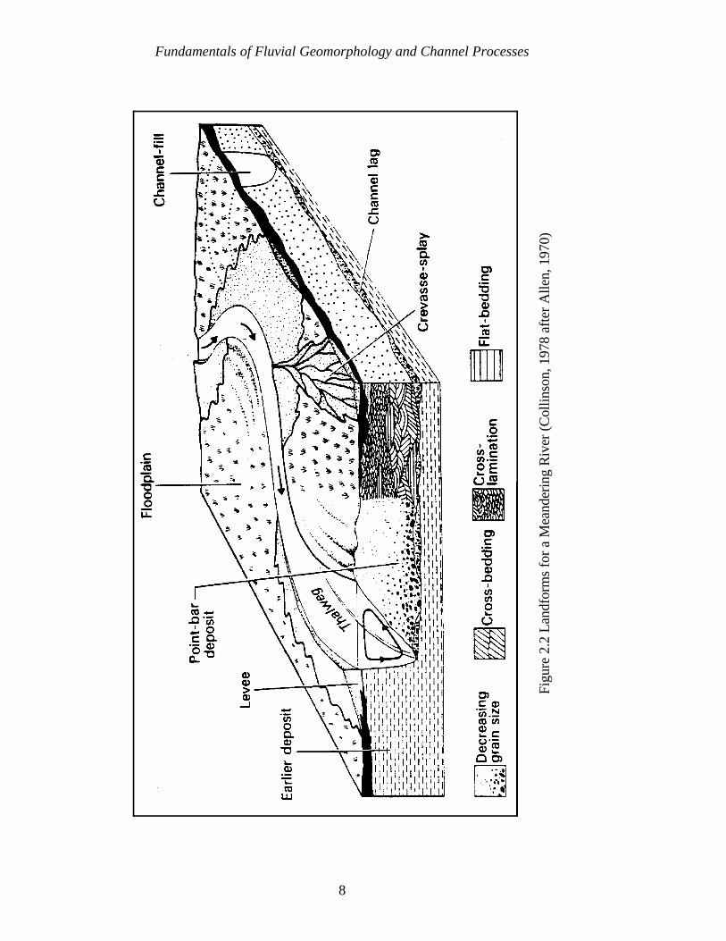
Figure 2.2 Landforms for a Meandering River (Collinson, 1978 after Allen, 1970) . . . . . . . . . . . . . . . . . . . . . . . . . . . . . . . . . . . . . . . . . . . . 8
Figure 2.3 Typical Meandering River . . . . . . . . . . . . . . . . . . . . . . . . . . . . . . . . . . 12
Figure 2.4 Typical Braided River . . . . . . . . . . . . . . . . . . . . . . . . . . . . . . . . . . . . . 12
Figure 2.5 Features Associated With (a) Straight and (b) Meandering Rivers . . . . 13
Figure 2.6 Typical Plan and Cross Sectional View of Pools and Crossings . . . . . . 14
Figure 2.7 Typical Middle Bar . . . . . . . . . . . . . . . . . . . . . . . . . . . . . . . . . . . . . . . 16
Figure 2.8 Typical Alternate Bar Pattern . . . . . . . . . . . . . . . . . . . . . . . . . . . . . . . . 16
Figure 2.9 Definition Sketch for Channel Geometry (after Leopold et al., 1964) . . . . . . . . . . . . . . . . . . . . . . . . . . . . . . . . . . . . . . . . . . . . . . . . . . 17
Figure 2.10 Lane’s (1957) Relationship Between Channel Patterns, Channel Gradient, and Mean Discharge . . . . . . . . . . . . . . . . . . . . . . . . . . . . . . . 19
Figure 2.11 Leopold and Wolman’s (1957) Relationship Between ChannelPatterns, Channel Gradient, and Bankfull Discharge . . . . . . . . . . . . . . . 19
Figure 2.12 Channel Classification Based on Pattern and Type of Sediment Load (after Schumm, 1981) . . . . . . . . . . . . . . . . . . . . . . . . . . . . . . . . . 24
Figure 2.13 Channel Classification Combining Aspects of Schumm (1981) andRosgen (1994) . . . . . . . . . . . . . . . . . . . . . . . . . . . . . . . . . . . . . . . . . . . 27
Figure 2.14 Lane’s Balance (after E. W. Lane, from W. Borland) . . . . . . . . . . . . . . 29
xii
Figure 2.15 Consequences of System Instability, (a) Bed and Bank Instability,(b) Formation of Gulllies in Floodplain, (c) Damage to Infrastructure, (d) Excessive Sediment Deposition in Lower Reaches of Watershed . . . . . . . . . . . . . . . . . . . . . . . . . . . . . . . . . . . . . 31
Figure 2.16 Channelized Stream and Abandoned Old Channel . . . . . . . . . . . . . . . . 34
Figure 2.17 Knickpoint in a Degrading Channel . . . . . . . . . . . . . . . . . . . . . . . . . . . 34
Figure 2.18 Knickzone in a Degrading Channel . . . . . . . . . . . . . . . . . . . . . . . . . . . 35
Figure 2.19 Erosion Generated by Parallel Flow . . . . . . . . . . . . . . . . . . . . . . . . . . . 41
Figure 2.20 Erosion Generated by Impinging Flow . . . . . . . . . . . . . . . . . . . . . . . . . 41
Figure 2.21 Erosion Generated by Piping . . . . . . . . . . . . . . . . . . . . . . . . . . . . . . . . 42
Figure 2.22 Erosion Generated by Freeze/Thaw . . . . . . . . . . . . . . . . . . . . . . . . . . . 42
Figure 2.23 Sheet Erosion with Rilling and Gullying . . . . . . . . . . . . . . . . . . . . . . . 43
Figure 2.24 Erosion Generated by Wind Waves . . . . . . . . . . . . . . . . . . . . . . . . . . . 43
Figure 2.25 Erosion Generated by Vessel Forces . . . . . . . . . . . . . . . . . . . . . . . . . . 44
Figure 2.26 Soil Fall . . . . . . . . . . . . . . . . . . . . . . . . . . . . . . . . . . . . . . . . . . . . . . . 47
Figure 2.27 Rotational Slip . . . . . . . . . . . . . . . . . . . . . . . . . . . . . . . . . . . . . . . . . . 47
Figure 2.28 Slab Failure . . . . . . . . . . . . . . . . . . . . . . . . . . . . . . . . . . . . . . . . . . . . . 48
Figure 2.29 Cantilever Failure . . . . . . . . . . . . . . . . . . . . . . . . . . . . . . . . . . . . . . . . 48
Figure 2.30 Pop-out Failure . . . . . . . . . . . . . . . . . . . . . . . . . . . . . . . . . . . . . . . . . . 49
Figure 2.31 Piping . . . . . . . . . . . . . . . . . . . . . . . . . . . . . . . . . . . . . . . . . . . . . . . . . 49
Figure 2.32 Dry Granular Flow . . . . . . . . . . . . . . . . . . . . . . . . . . . . . . . . . . . . . . . 50
Figure 2.33 Wet Earth Flow . . . . . . . . . . . . . . . . . . . . . . . . . . . . . . . . . . . . . . . . . . 50
Figure 2.34 Cattle Trampling . . . . . . . . . . . . . . . . . . . . . . . . . . . . . . . . . . . . . . . . . 51
xiii
Figure 3.1 The Formation of Berms Can Indicate a Tendency for the Channelto Re-establish Stability Following a Period of Morphological Change . . . . . . . . . . . . . . . . . . . . . . . . . . . . . . . . . . . . . . . . . . . . . . . 64
Figure 3.2 Terrace Formation in an Incised Channel . . . . . . . . . . . . . . . . . . . . . . 64
Figure 3.3 Specific Gage Plot for Red River at Index, Arkansas . . . . . . . . . . . . . 67
Figure 3.4 Comparative Thalweg Profiles . . . . . . . . . . . . . . . . . . . . . . . . . . . . . . 69
Figure 6.1 Classic Planforms for Straight and Sinuous Channels . . . . . . . . . . . . . 122
Figure 6.2 Effects of Varying Bed and Bank Materials on Planform Characteristics . . . . . . . . . . . . . . . . . . . . . . . . . . . . . . . . . . . . . . . . . . 123
Figure 6.3 Upstream and Downstream Limits of Bank Protection for aSinuous and Straight Channel . . . . . . . . . . . . . . . . . . . . . . . . . . . . . . 125
Figure 6.4 Top Elevation of Protection . . . . . . . . . . . . . . . . . . . . . . . . . . . . . . . . 133
Figure 6.5 Construction of Berm or Levee to Control Overbank Drainage . . . . . 144
Figure 7.1 Typical Cross Section of a Trenchfill Revetment . . . . . . . . . . . . . . . . 150
Figure 7.2 Aerial View of Trenchfill Revetment With Foreshore Material Stillin Place . . . . . . . . . . . . . . . . . . . . . . . . . . . . . . . . . . . . . . . . . . . . . . . 150
Figure 7.3 Schematic Diagram of Windrow Revetment . . . . . . . . . . . . . . . . . . . . 154
Figure 7.4 Conventional Windrow Placed on Top Bank . . . . . . . . . . . . . . . . . . . 155
Figure 7.5 Placement of Windrow Rock in Excavated Trench on Top Bank . . . . 155
Figure 7.6 Launched Windrow Rock . . . . . . . . . . . . . . . . . . . . . . . . . . . . . . . . . 156
Figure 7.7 Typical Longitudinal Peaked Stone Toe Protection, (a) One TonPer Foot Immediately After Construction, (b) Same Site One Year Later . . . . . . . . . . . . . . . . . . . . . . . . . . . . . . . . . . . . . . . . . . . . . 160
Figure 7.8 Typical Longitudinal Peaked Stone Toe Protection With Tiebacks . . . . . . . . . . . . . . . . . . . . . . . . . . . . . . . . . . . . . . . . . . . . . . 161
Figure 7.9 Longitudinal Peaked Stone Toe Protection in Combination WithWillow Post Upper Bank Protection . . . . . . . . . . . . . . . . . . . . . . . . . 163
xiv
Figure 7.10 Longitudinal Stone Fill Toe Protection Placed Adjacent to Bank With Tiebacks . . . . . . . . . . . . . . . . . . . . . . . . . . . . . . . . . . . . . . . . . . 164
Figure 7.11 Longitudinal Stone Fill Toe Protection Riverward of High Bank With Tiebacks . . . . . . . . . . . . . . . . . . . . . . . . . . . . . . . . . . . . . . . . . . 164
Figure 7.12 Typical Sack Revetment . . . . . . . . . . . . . . . . . . . . . . . . . . . . . . . . . . 169
Figure 7.13 Typical Soil Cement Application . . . . . . . . . . . . . . . . . . . . . . . . . . . . 177
Figure 8.1 Typical Permeable Dikes, (a) Palisades, (b) Board Fence Dikes . . . . . . . . . . . . . . . . . . . . . . . . . . . . . . . . . . . . . . . . . . . . . . . . 206
Figure 8.2 Typical Impermeable Dikes . . . . . . . . . . . . . . . . . . . . . . . . . . . . . . . . 208
Figure 8.3 Typical Permeable Retards, (a) Board Fence Retard, (b) Jack Field . . . . . . . . . . . . . . . . . . . . . . . . . . . . . . . . . . . . . . . . . . 212
Figure 8.4 Bendway Weirs on Small Streams, (a) Bendway Weirs on HarlandCreek, (b) Bendway Weirs in Combination With Longitudinal Peaked Stone Toe Protection . . . . . . . . . . . . . . . . . . . . . . . . . . . . . . 215
Figure 12.1 Spacing of Grade Control Structure (adapted from Mussetter, 1982) . . . . . . . . . . . . . . . . . . . . . . . . . . . . . . . . . . . . . . . . 249
Figure 12.2 Combination Grade Control Structure and Road Crossing(adapted from U.S. Soil Conservation Service, 1976) . . . . . . . . . . . . 253
Figure 12.3 Channel Stabilization With Rock Sills (adapted from Whitaker and Jaggi, 1986) . . . . . . . . . . . . . . . . . . . . . . . . . . . . . . . . . . . . . . . . . . . 257
Figure 12.4a As Built Riprap Grade Control Structure with Sufficient LaunchStone to Handle Anticipated Scour . . . . . . . . . . . . . . . . . . . . . . . . . . 258
Figure 12.4b Launching of Riprap at Grade Control Structure in Response to Bed Degradation and Local Scour . . . . . . . . . . . . . . . . . . . . . . . . . 258
Figure 12.5a As Built Riprap Grade Control Structure with Impervious FillCutoff Wall . . . . . . . . . . . . . . . . . . . . . . . . . . . . . . . . . . . . . . . . . . . . 259
Figure 12.5b Launching of Riprap at Grade Control Structure in Response to Bed Degradation and Local Scour . . . . . . . . . . . . . . . . . . . . . . . . . 259
Figure 12.6a As Built Riprap Grade Control Structure with Sheet Pile Cutoff Wall . . . . . . . . . . . . . . . . . . . . . . . . . . . . . . . . . . . . . . . . . . . . . . . . . 260
xv
Figure 12.6b Launching of Riprap at Grade Control Structure in Response to Bed Degradation and Local Scour . . . . . . . . . . . . . . . . . . . . . . . . . 260
Figure 12.7 Sloping Drop Grade Control Structure with Pre-formed RiprapLined Scour Hole (McLaughlin Water Engineers, 1986) . . . . . . . . . . 261
Figure 12.8 Bed Stabilizer Design with Sheet Pile Cutoff (U.S. Army Corps of Engineers, 1970) . . . . . . . . . . . . . . . . . . . . . . . . . . . . . . . . . . . . . . 263
Figure 12.9 ARS-Type Grade Control Structure with Pre-formed Riprap LinedStilling Basin and Baffle Plate (Little and Murphey, 1982) . . . . . . . . . 264
Figure 12.10 Schematic of Modified ARS-Type Grade Control Structure (Abt et al., 1994) . . . . . . . . . . . . . . . . . . . . . . . . . . . . . . . . . . . . . . . . 265
Figure 12.11 CIT-Type Drop Structure (Murphy, 1967) . . . . . . . . . . . . . . . . . . . . 267
Figure 12.12 St. Anthony Falls (SAF) Type Drop Structure (Blaisdell, 1948) . . . . . . . . . . . . . . . . . . . . . . . . . . . . . . . . . . . . . . . . 268
Figure 12.13 Riprap Lined Drop Structures (adapted from Tate, 1991) . . . . . . . . . 269

xvi
LIST OF TABLES
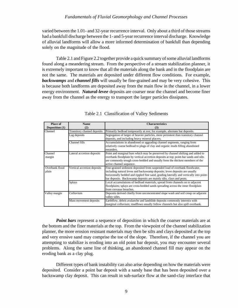
Table 2.1 Classification of Valley Sediments . . . . . . . . . . . . . . . . . . . . . . . . . . . 9
Table 2.2 Classification of Alluvial Channels (after Schumm, 1977) . . . . . . . . . 23
Table 2.3 Summary of Delineative Criteria for Broad-level Classification(Rosgen, 1994) . . . . . . . . . . . . . . . . . . . . . . . . . . . . . . . . . . . . . . . . . 25
Table 5.1 General Matrix for Selection of Erosion Protection Method . . . . . . . 115
Table 5.2 Example of Very Simple Environmental Sub-matrix . . . . . . . . . . . . . 116
1
CHAPTER 1
INTRODUCTION
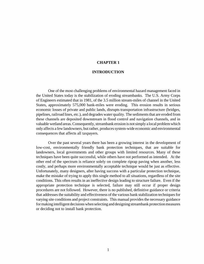
One of the most challenging problems of environmental hazard management faced inthe United States today is the stabilization of eroding streambanks. The U.S. Army Corpsof Engineers estimated that in 1981, of the 3.5 million stream-miles of channel in the UnitedStates, approximately 575,000 bank-miles were eroding. This erosion results in seriouseconomic losses of private and public lands, disrupts transportation infrastructure (bridges,pipelines, railroad lines, etc.), and degrades water quality. The sediments that are eroded fromthese channels are deposited downstream in flood control and navigation channels, and invaluable wetland areas. Consequently, streambank erosion is not simply a local problem whichonly affects a few landowners, but rather, produces system-wide economic and environmentalconsequences that affects all taxpayers.
Over the past several years there has been a growing interest in the development oflow-cost, environmentally friendly bank protection techniques, that are suitable forlandowners, local governments and other groups with limited resources. Many of thesetechniques have been quite successful, while others have not performed as intended. At theother end of the spectrum is reliance solely on complete riprap paving when another, lesscostly, and perhaps more environmentally acceptable technique would be just as effective.Unfortunately, many designers, after having success with a particular protection technique,make the mistake of trying to apply this single method to all situations, regardless of the siteconditions. This often results in an ineffective design leading to structure failure. Even if theappropriate protection technique is selected, failure may still occur if proper designprocedures are not followed. However, there is no published, definitive guidance or criteriathat addresses the suitability and effectiveness of the various bank stabilization techniques forvarying site conditions and project constraints. This manual provides the necessary guidancefor making intelligent decisions when selecting and designing streambank protection measuresor deciding not to install bank protection.
Introduction
2
1.1 PURPOSE
Bank stabilization structures are often considered to be very simple features requiringvery little planning and design effort. However, the hydraulic and geomorphic processesassociated with these structures are as complex and challenging as those of many of the moreelaborate hydraulic structures, and in many cases their design is even more complicated dueto the lack of definitive design guidance. This manual is designed to provide general guidancefor the design, construction, and monitoring of streambank protection projects. It alsointroduces the reader to the basic concepts of channel stability, and procedures forunderstanding and analyzing stream processes.
1.2 SCOPE
There are hundreds of different types of possible bank stabilization techniques whichare used on a wide range of stream types and physical environments ranging from theMississippi River to small ephemeral streams draining only a few square miles. A range ofstructure types and applications is presented, from traditional techniques such as riprap bankpaving, stone dikes, and retards, to the low-cost and innovative techniques such as bendwayweirs, and bio-engineering measures. This is a comprehensive manual covering a wide rangeof techniques and design guidance that will be of benefit to all groups, large or small,undertaking a streambank protection project. Whenever possible, layman’s language is usedin this manual, so that the information and guidance contained herein can be utilized by thebroadest possible audience.
3
CHAPTER 2
FUNDAMENTALS OF FLUVIAL GEOMORPHOLOGY AND
CHANNEL PROCESSES
2.1 FLUVIAL GEOMORPHOLOGY
Webster's New World Dictionary defines fluvial as: of, found in, or produced by ariver or rivers. The same reference defines morphology as: any scientific study of form andstructure, as in physical geography, etc. With a little guess work, we can correctlyextrapolate that fluvial geomorphology is the study of the form and structure of the surfaceof the earth (geo) as affected by flowing water. Another definition, although given in jest,may be the one most remembered after this next section. Geomorphology is the triumph ofterminology over common sense. An equally important term is the fluvial system. A systemis an arrangement of things to form a whole. The primary goal on which we want to focusin this section is that you are working with a system and the complete system must beconsidered.
2.1.1 BASIC CONCEPTS
Six basic concepts that should be considered in working with watersheds and riversare: 1) the river is only part of a system, 2) the system is dynamic, 3) the system behaves withcomplexity, 4) geomorphic thresholds exist, and when exceeded, can result in abrupt changes,5) geomorphic analyses provide a historical prospective and we must be aware of the timescale, and 6) the scale of the stream must be considered. Is the stream a small, mountainmeadow trout stream, or is it the Mississippi River?
2.1.1.1 The Fluvial System
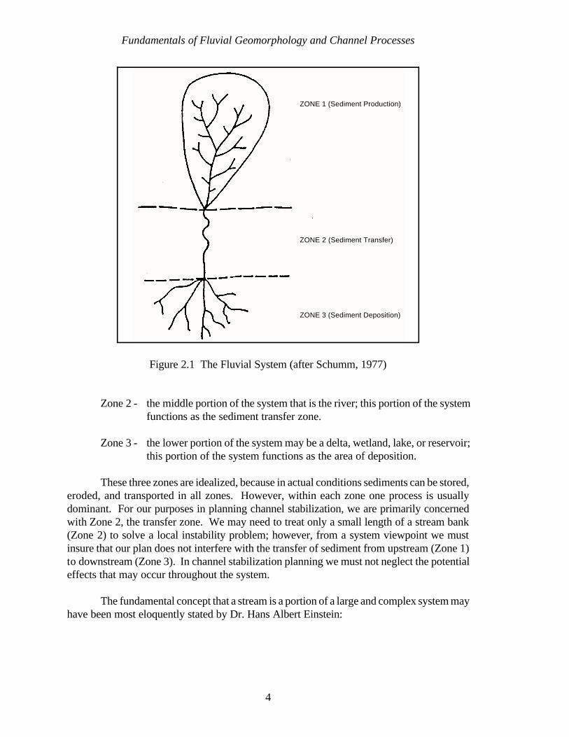
Schumm (1977) provides an idealized sketch of a fluvial system (Figure 2.1). Theparts are referred to as:
Zone 1 - the upper portion of the system that is the watershed or drainagebasin; this portion of the system functions as the sediment supply.
Fundamentals of Fluvial Geomorphology and Channel Processes
4
ZONE 1 (Sediment Production)
ZONE 2 (Sediment Transfer)
ZONE 3 (Sediment Deposition)
Figure 2.1 The Fluvial System (after Schumm, 1977)
Zone 2 - the middle portion of the system that is the river; this portion of the systemfunctions as the sediment transfer zone.
Zone 3 - the lower portion of the system may be a delta, wetland, lake, or reservoir;this portion of the system functions as the area of deposition.
These three zones are idealized, because in actual conditions sediments can be stored,eroded, and transported in all zones. However, within each zone one process is usuallydominant. For our purposes in planning channel stabilization, we are primarily concernedwith Zone 2, the transfer zone. We may need to treat only a small length of a stream bank(Zone 2) to solve a local instability problem; however, from a system viewpoint we mustinsure that our plan does not interfere with the transfer of sediment from upstream (Zone 1)to downstream (Zone 3). In channel stabilization planning we must not neglect the potentialeffects that may occur throughout the system.
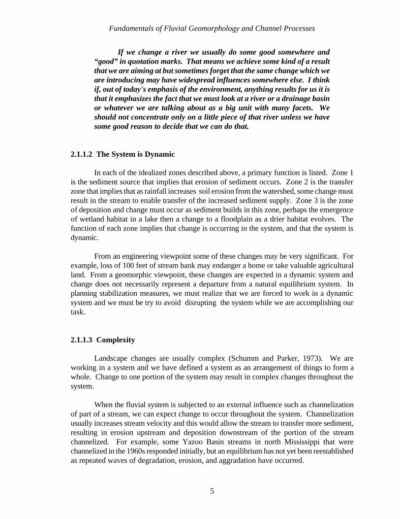
The fundamental concept that a stream is a portion of a large and complex system mayhave been most eloquently stated by Dr. Hans Albert Einstein:
Fundamentals of Fluvial Geomorphology and Channel Processes
5
If we change a river we usually do some good somewhere and“good” in quotation marks. That means we achieve some kind of a resultthat we are aiming at but sometimes forget that the same change which weare introducing may have widespread influences somewhere else. I thinkif, out of today's emphasis of the environment, anything results for us it isthat it emphasizes the fact that we must look at a river or a drainage basinor whatever we are talking about as a big unit with many facets. Weshould not concentrate only on a little piece of that river unless we havesome good reason to decide that we can do that.
2.1.1.2 The System is Dynamic
In each of the idealized zones described above, a primary function is listed. Zone 1is the sediment source that implies that erosion of sediment occurs. Zone 2 is the transferzone that implies that as rainfall increases soil erosion from the watershed, some change mustresult in the stream to enable transfer of the increased sediment supply. Zone 3 is the zoneof deposition and change must occur as sediment builds in this zone, perhaps the emergenceof wetland habitat in a lake then a change to a floodplain as a drier habitat evolves. Thefunction of each zone implies that change is occurring in the system, and that the system isdynamic.
From an engineering viewpoint some of these changes may be very significant. Forexample, loss of 100 feet of stream bank may endanger a home or take valuable agriculturalland. From a geomorphic viewpoint, these changes are expected in a dynamic system andchange does not necessarily represent a departure from a natural equilibrium system. Inplanning stabilization measures, we must realize that we are forced to work in a dynamicsystem and we must be try to avoid disrupting the system while we are accomplishing ourtask.
2.1.1.3 Complexity
Landscape changes are usually complex (Schumm and Parker, 1973). We areworking in a system and we have defined a system as an arrangement of things to form awhole. Change to one portion of the system may result in complex changes throughout thesystem.
When the fluvial system is subjected to an external influence such as channelizationof part of a stream, we can expect change to occur throughout the system. Channelizationusually increases stream velocity and this would allow the stream to transfer more sediment,resulting in erosion upstream and deposition downstream of the portion of the streamchannelized. For example, some Yazoo Basin streams in north Mississippi that werechannelized in the 1960s responded initially, but an equilibrium has not yet been reestablishedas repeated waves of degradation, erosion, and aggradation have occurred.
Fundamentals of Fluvial Geomorphology and Channel Processes
6
2.1.1.4 Thresholds
Geomorphic thresholds may be thought of as the straw that broke the camel's back.In the fluvial system this means that progressive change in one variable may eventually resultin an abrupt change in the system. If a river erodes a few grains of soil from the toe of theriver bank, no particular response will be noticed. If that continues with no deposition tobalance the loss, the bank may eventually fail abruptly and dramatically due to undermining.The amount of flow impinging along a bank may vary considerably with no apparent effecton the stabilization; however, at some critical point the bank material will begin to move anddisastrous consequences can result.
In these examples the change was a gradual erosion of a few grains of soil and avariability of stream velocity, both which could be considered to be within the natural system.This type of threshold would be called an intrinsic threshold. Perhaps the threshold wasexceeded due to an earthquake or caused by an ill-planned bank stabilization project. Thesewould be called an extrinsic threshold. The planner must be aware of geomorphic thresholds,and the effect that their project may have in causing the system to exceed the threshold.
Channel systems have a measure of elasticity that enables change to be absorbed bya shift in equilibrium. The amount of change a system can absorb before that naturalequilibrium is disturbed depends on the sensitivity of the system, and if the system is near athreshold condition, a minor change may result in a dramatic response.
2.1.1.5 Time
We all have been exposed to the geologists view of time. The Paleozoic Era endedonly 248 million years ago, the Mesozoic Era ended only 65 million years ago, and so on.Fortunately, we do not have to concern ourselves with that terminology. An aquaticbiologist may be concerned with the duration of an insect life stage, only a few hours or days.What we should be aware of is that the geologist temporal perspective is much broader thanthe temporal perspective of the engineer, and the biologist perspective may be a narrowlyfocused time scale. Neither profession is good nor bad because of the temporal perspective;just remember the background of people or the literature with which you are working.
Geomorphologists usually refer to three time scales in working with rivers: 1)geologic time, 2) modern time, and 3) present time. Geologic time is usually expressed inthousands or millions of years and in this time scale only major geologic activity would besignificant. Formation of mountain ranges, changes in sea level, and climate change wouldbe significant in this time scale. The modern time scale describes a period of tens of years toseveral hundred years, and has been called the graded time scale (Schumm and Lichty, 1965).During this period a river may adjust to a balanced condition, adjusting to watershed waterand sediment discharge. The present time is considered a shorter period, perhaps one yearto ten years. No fixed rules govern these definitions. Design of a major project may require

Fundamentals of Fluvial Geomorphology and Channel Processes
7
less than ten years, and numerous minor projects are designed and built within the limitationsof present time. Project life often extends into graded time. From a geologists temporal pointof view, engineers built major projects in an instant of time, and expect the projects to last fora significant period.
In river related projects time is the enemy, time is our friend, and time is our teacher.We must learn all we can by adopting a historical perspective for each project that weundertake.
2.1.1.6 Scale
The physical size of the stream may impose limits on the type of plannedenhancements to the stream. For example, many variations of anchoring trees along the bankhave been successfully used along small and moderate size streams to provide cover and todecrease erosion of the bank. Anchoring of trees along the bank is a reasonable method ofstabilization. However, for large rivers that may have bank heights of 30 feet and a yearlywater surface elevation fluctuation of 20 to 30 feet, the anchored tree may be an unreasonablemethod for stabilization. Applications designed for a small stream may not be directlytransferrable to larger streams. If we are to transfer techniques for enhancement from streamto stream; we must also understand the design principles of those techniques. Principles, suchas increasing the cover and decreasing the water velocity at the water-bank interface aretransferable; however, the direct technique may not be transferable.
2.1.2 LANDFORMS
Now it is time to give you a brief introduction into what you may see when you goto the field. The following discussion will be confined primarily to depositional landformsalong meandering rivers, and a little information concerning terraces.
A floodplain is the alluvial surface adjacent to a channel that is frequently inundated(Figure 2.2). This is a simple definition of a floodplain; however, the concept that thebankfull discharge is the sole discriminator between channel-forming and floodplain-buildingprocess is especially difficult. Although much of the literature until the 1970s suggested thatthe mean annual flood was the bankfull discharge, Williams (1978) clearly showed that outof thirty-five floodplains he studied in the U.S., the bankfull discharge
Fundamentals of Fluvial Geomorphology and Channel Processes
8
Figu
re 2
.2 L
andf
orm
s fo
r a
Mea
nder
ing
Riv
er (
Col
linso
n, 1
978
afte
r A
llen,
197
0)
Fundamentals of Fluvial Geomorphology and Channel Processes
9
varied between the 1.01- and 32-year recurrence interval. Only about a third of those streamshad a bankfull discharge between the 1- and 5-year recurrence interval discharge. Knowledgeof alluvial landforms will allow a more informed determination of bankfull than dependingsolely on the magnitude of the flood.
Table 2.1 and Figure 2.2 together provide a quick summary of some alluvial landformsfound along a meandering stream. From the perspective of a stream stabilization planner, itis extremely important to know that all the materials along the bank and in the floodplain arenot the same. The materials are deposited under different flow conditions. For example,backswamps and channel fills will usually be fine-grained and may be very cohesive. Thisis because both landforms are deposited away from the main flow in the channel, in a lowerenergy environment. Natural-levee deposits are coarser near the channel and become fineraway from the channel as the energy to transport the larger particles dissipates.
Table 2.1 Classification of Valley Sediments
Place ofDeposition (1)
Name(2)
Characteristics(3)
Channel Transitory channel deposits Primarily bedload temporarily at rest; for example, alternate bar deposits.Lag deposits Segregation of larger of heavier particles, more persistent than transitory channel
deposits, and including heavy mineral placers.Channel fills Accumulations in abandoned or aggrading channel segments, ranging from
relatively coarse bedload to plugs of clay and organic muds filling abandonedmeanders.
Channel margin
Lateral accretion deposits Point and marginal bars which may be preserved by channel shifting and added tooverbank floodplain by vertical accretion deposits at top; point-bar sands and siltsare commonly trough cross-bedded and usually form the thickest members of theactive channel sequence.
Overbank flood plain
Vertical accretion deposits Fine-grained sediment deposited from suspended load of overbank floodwater,including natural levee and backswamp deposits; levee deposits are usuallyhorizontally bedded and rippled fine sand, grading laterally and vertically into point-bar deposits. Backswamp deposits are mainly silts, clays and peats.
Splays Local accumulations of bedload materials, spread from channels on to adjacentfloodplains; splays are cross-bedded sands spreading across the inner floodplainfrom crevasse breaches.
Valley margin Colluvium Deposits derived chiefly from unconcentrated slope wash and soil creep on adjacentvalley sides.
Mass movement deposits Earthflow, debris avalanche and landslide deposits commonly intermix withmarginal colluvium; mudflows usually follow channels but also spill overbank.
Point bars represent a sequence of deposition in which the coarser materials are atthe bottom and the finer materials at the top. From the viewpoint of the channel stabilizationplanner, the more erosion resistant materials may then be silts and clays deposited at the topand very erosive sand may comprise the toe of the slope. Therefore, if the channel you areattempting to stabilize is eroding into an old point bar deposit, you may encounter severalproblems. Along the same line of thinking, an abandoned channel fill may appear on theeroding bank as a clay plug.
Different types of bank instability can also arise depending on how the materials weredeposited. Consider a point bar deposit with a sandy base that has been deposited over abackswamp clay deposit. This can result in sub-surface flow at the sand-clay interface that
Fundamentals of Fluvial Geomorphology and Channel Processes
10
can cause the granular material to be washed out of the bank and failure to occur somedistance back from the channel. Stabilization could include proper drainage of the top of thebank to deprive the failure mechanism of the percolating groundwater source.
In addition to the landforms briefly described in Table 2.1, we should introduceterraces. Terraces are abandoned floodplains formed when the river flowed at a higher levelthan now (Ritter, 1978). Terraces are produced by incision of the floodplain (Schumm,1977). In other words, the stream channel has down cut leaving the previous floodplain, andis establishing a new, lower floodplain. The appearance of a terrace or a series of terraces ina surveyed cross-section may be as broad stair steps down to the stream. The steps may bebroad and continuous throughout the length of the stream segment, or may be discontinuousand could be only a few feet in width.
2.1.3 RIVER MECHANICS
River mechanics is the subset of both fluvial geomorphology and open channelhydraulics which focuses on the form and structure of rivers. Specifically it address thechannel pattern, channel geometry (cross section shape), planform geometry, and the channelslope. The purpose of this section is to introduce you to some of the basic characteristics ofrivers, and help define some of the confusing terminology you may encounter when dealingwith rivers.
2.1.4 RIVER CHARACTERISTICS AND BASIC DEFINITIONS
Rivers and streams are dynamic and continuously change their position, shape, andother morphological characteristics with variations in discharge and with the passage of time.It is important not only to study the existing river but also the possible variations during thelifetime of the project, particularly in terms of effective treatment of bank erosion. Thecharacteristics of the river are determined by the water discharge, the quantity and characterof sediment discharge, the composition of the bed and bank material of the channel, geologiccontrols, the variations of these parameters in time, and man's activities. To predict thebehavior of a river in a natural state or as affected by man's activities, we must understand thecharacteristics of the river as well as the mechanics of formation.
Fundamentals of Fluvial Geomorphology and Channel Processes
11
2.1.4.1 Channel Pattern
Channel pattern describes the planform of a channel. The primary types of planformare meandering, braided, and straight. In many cases, a stream will change pattern within itslength. The type pattern is dependent on slope, discharge, and sediment load.
The most common channel pattern is the meandering stream (Figure 2.3). Ameandering channel is one that is formed by a series of alternating changes in direction, orbends. Relatively straight reaches of alluvial rivers rarely occur in nature. However, there areinstances where a reach of river will maintain a nearly straight alignment for a long periodof time. Even in these relatively straight reaches, the thalweg may still meander and alternatebars may be formed. Straight streams generally occur in relatively low energy environments.The braided pattern is characterized by a division of the river bed into multiple channels(Figure 2.4). Most braided streams are relatively high gradient and relatively coarse streams.
2.1.4.2 Channel Geometry and Cross Section
The following paragraphs describe the channel geometry and cross sectionalcharacteristics of streams. Since meandering streams are the most common form of alluvialchannels this discussion will focus primarily on this stream type.
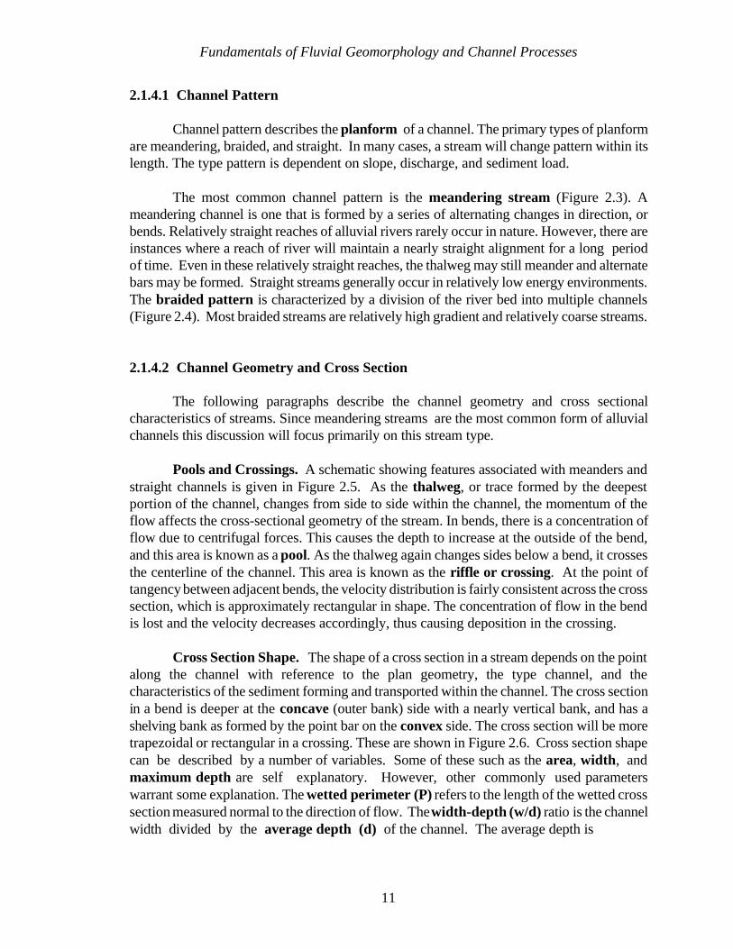
Pools and Crossings. A schematic showing features associated with meanders andstraight channels is given in Figure 2.5. As the thalweg, or trace formed by the deepestportion of the channel, changes from side to side within the channel, the momentum of theflow affects the cross-sectional geometry of the stream. In bends, there is a concentration offlow due to centrifugal forces. This causes the depth to increase at the outside of the bend,and this area is known as a pool. As the thalweg again changes sides below a bend, it crossesthe centerline of the channel. This area is known as the riffle or crossing. At the point oftangency between adjacent bends, the velocity distribution is fairly consistent across the crosssection, which is approximately rectangular in shape. The concentration of flow in the bendis lost and the velocity decreases accordingly, thus causing deposition in the crossing.
Cross Section Shape. The shape of a cross section in a stream depends on the pointalong the channel with reference to the plan geometry, the type channel, and thecharacteristics of the sediment forming and transported within the channel. The cross sectionin a bend is deeper at the concave (outer bank) side with a nearly vertical bank, and has ashelving bank as formed by the point bar on the convex side. The cross section will be moretrapezoidal or rectangular in a crossing. These are shown in Figure 2.6. Cross section shapecan be described by a number of variables. Some of these such as the area, width, andmaximum depth are self explanatory. However, other commonly used parameterswarrant some explanation. The wetted perimeter (P) refers to the length of the wetted crosssection measured normal to the direction of flow. The width-depth (w/d) ratio is the channelwidth divided by the average depth (d) of the channel. The average depth is

Fundamentals of Fluvial Geomorphology and Channel Processes
12
Figure 2.3 Typical Meandering River
Figure 2.4 Typical Braided River

Fundamentals of Fluvial Geomorphology and Channel Processes
13
(a) Straight
(b) Meandering
Figure 2.5 Features Associated With (a) Straight and (b) Meandering Rivers
Fundamentals of Fluvial Geomorphology and Channel Processes
14
Figure 2.6 Typical Plan and Cross Sectional View of Pools and Crossings
calculated by dividing the cross section area by the channel width. The hydraulic radius (r),which is important in hydraulic computations is defined as the cross sectional area divided bythe wetted perimeter. In wide channels with w/d greater than about 20 the hydraulic radiusand the mean depth are approximately equal. The conveyance, or capacity of a channel isrelated to the area and hydraulic radius and is defined as AR2/3.
Channel Bars. Channel bars are depositional features that occur within the channel.The size and location of bars are related to the sediment transport capacity and local geometryof the reach. The enlargement of a bar generally results in caving of the opposite banks inorder to maintain conveyance of the discharge. The primary types of bars are point bars,middle bars, and alternate bars.
Point bars form on the inside (convex) bank of bends in a meandering stream. Atypical point bar is shown in Figure 2.3. The size and shape of the point bar are determinedby the characteristics of the flow. The development of a point bar is partially due to the flow
Fundamentals of Fluvial Geomorphology and Channel Processes
15
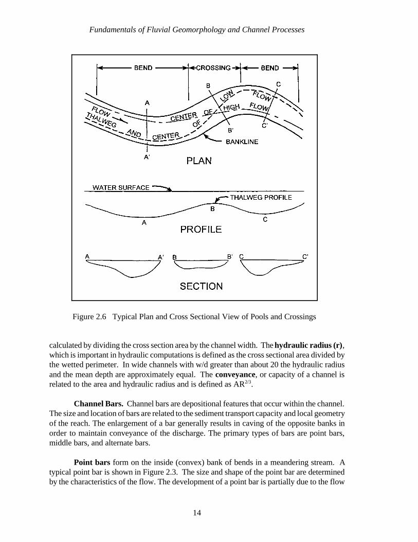
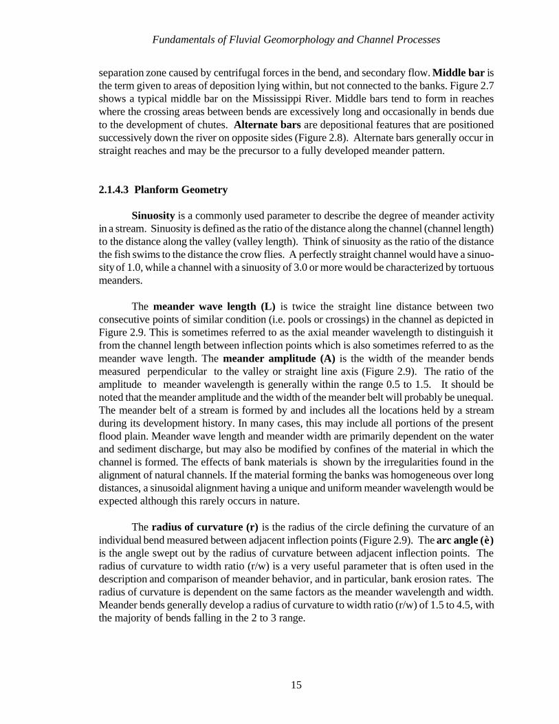
separation zone caused by centrifugal forces in the bend, and secondary flow. Middle bar isthe term given to areas of deposition lying within, but not connected to the banks. Figure 2.7shows a typical middle bar on the Mississippi River. Middle bars tend to form in reacheswhere the crossing areas between bends are excessively long and occasionally in bends dueto the development of chutes. Alternate bars are depositional features that are positionedsuccessively down the river on opposite sides (Figure 2.8). Alternate bars generally occur instraight reaches and may be the precursor to a fully developed meander pattern.
2.1.4.3 Planform Geometry
Sinuosity is a commonly used parameter to describe the degree of meander activityin a stream. Sinuosity is defined as the ratio of the distance along the channel (channel length)to the distance along the valley (valley length). Think of sinuosity as the ratio of the distancethe fish swims to the distance the crow flies. A perfectly straight channel would have a sinuo-sity of 1.0, while a channel with a sinuosity of 3.0 or more would be characterized by tortuousmeanders.
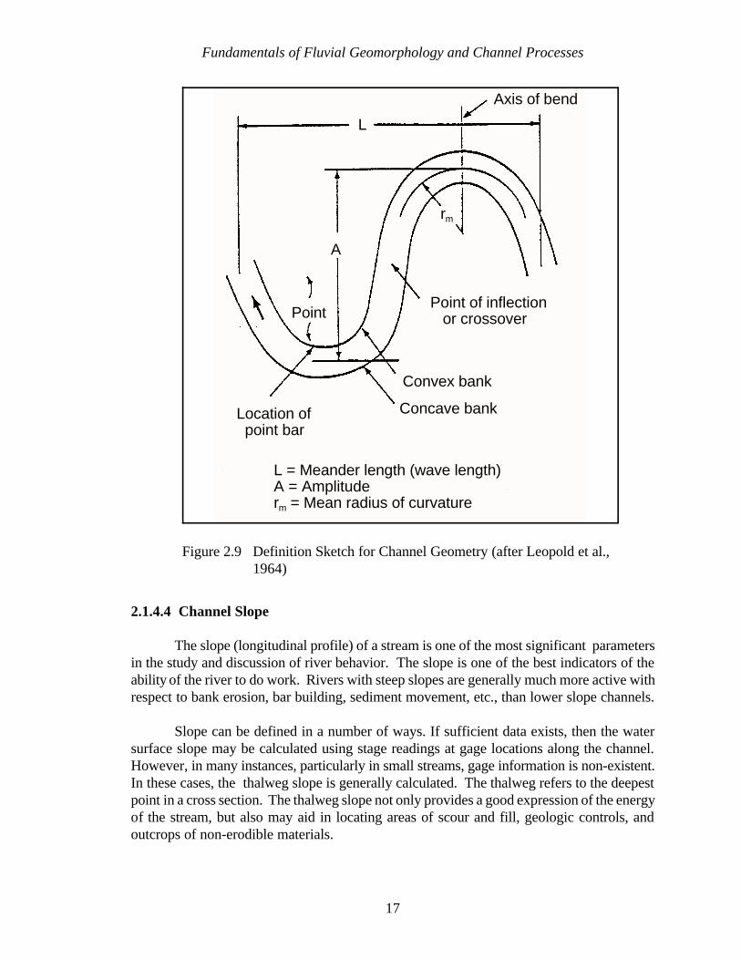
The meander wave length (L) is twice the straight line distance between twoconsecutive points of similar condition (i.e. pools or crossings) in the channel as depicted inFigure 2.9. This is sometimes referred to as the axial meander wavelength to distinguish itfrom the channel length between inflection points which is also sometimes referred to as themeander wave length. The meander amplitude (A) is the width of the meander bendsmeasured perpendicular to the valley or straight line axis (Figure 2.9). The ratio of theamplitude to meander wavelength is generally within the range 0.5 to 1.5. It should benoted that the meander amplitude and the width of the meander belt will probably be unequal.The meander belt of a stream is formed by and includes all the locations held by a streamduring its development history. In many cases, this may include all portions of the presentflood plain. Meander wave length and meander width are primarily dependent on the waterand sediment discharge, but may also be modified by confines of the material in which thechannel is formed. The effects of bank materials is shown by the irregularities found in thealignment of natural channels. If the material forming the banks was homogeneous over longdistances, a sinusoidal alignment having a unique and uniform meander wavelength would beexpected although this rarely occurs in nature.
The radius of curvature (r) is the radius of the circle defining the curvature of anindividual bend measured between adjacent inflection points (Figure 2.9). The arc angle (è)is the angle swept out by the radius of curvature between adjacent inflection points. Theradius of curvature to width ratio (r/w) is a very useful parameter that is often used in thedescription and comparison of meander behavior, and in particular, bank erosion rates. Theradius of curvature is dependent on the same factors as the meander wavelength and width.Meander bends generally develop a radius of curvature to width ratio (r/w) of 1.5 to 4.5, withthe majority of bends falling in the 2 to 3 range.
Fundamentals of Fluvial Geomorphology and Channel Processes
16
Figure 2.8 Typical Alternate Bar Pattern
Figure 2.7 Typical Middle Bar
Fundamentals of Fluvial Geomorphology and Channel Processes
17
L
Axis of bend
rm
A
Point of inflection or crossoverPoint
Location of point bar
Convex bank
Concave bank
L = Meander length (wave length)A = Amplituderm = Mean radius of curvature
Figure 2.9 Definition Sketch for Channel Geometry (after Leopold et al.,1964)
2.1.4.4 Channel Slope
The slope (longitudinal profile) of a stream is one of the most significant parametersin the study and discussion of river behavior. The slope is one of the best indicators of theability of the river to do work. Rivers with steep slopes are generally much more active withrespect to bank erosion, bar building, sediment movement, etc., than lower slope channels.
Slope can be defined in a number of ways. If sufficient data exists, then the watersurface slope may be calculated using stage readings at gage locations along the channel.However, in many instances, particularly in small streams, gage information is non-existent.In these cases, the thalweg slope is generally calculated. The thalweg refers to the deepestpoint in a cross section. The thalweg slope not only provides a good expression of the energyof the stream, but also may aid in locating areas of scour and fill, geologic controls, andoutcrops of non-erodible materials.

Fundamentals of Fluvial Geomorphology and Channel Processes
18
2.1.5 RELATIONSHIPS IN RIVERS
One interesting aspect of meandering rivers is the similarity in the proportion ofplanform characteristics. Various empirical relationships have been developed which relateradius of curvature and meander wavelength to channel width and discharge. Brice (1984)suggested that these similarities regardless of size, account for the fact that the meanderingplanform is sensibly independent of scale. In other words, if scale is ignored all meanderingrivers tend to look alike in plan view. This fact provides us with a glimmer of hope that wemight be able to develop some relationships to help explain the behavior of complex riversystems.
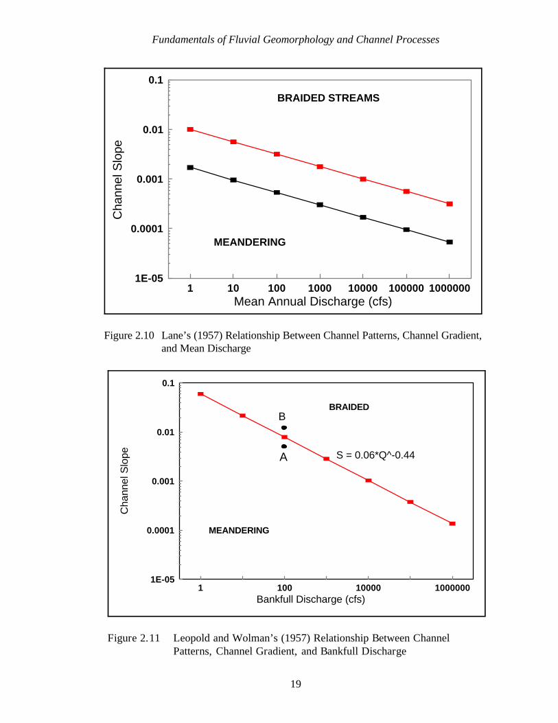
Investigation by Lane (1957) and Leopold and Wolman (1957) showed that therelationships between discharge and channel slope can define thresholds for indicating whichrivers tend to be braided or meandering, as shown in Figures 2.10 and 2.11. Lane'srelationship is somewhat more realistic because an intermediate range is included; however,both relationships are very similar in the variables used and the appearance of the graphs.Rivers that are near the threshold lines may exhibit segments that transitions between the twoplan forms. These relationships can be useful if the planform of a river is to be changed. Forinstance, a meandering river positioned at point ‘A’ in Figure 2.11 might be shifted to point‘B’ if the slope is increased due to the construction of man-made cutoffs. Shifting the channelinto the transition zone would cause some concern about the possibility of the channelbecoming braided.
Another set of empirical relationships is related to meander geometry. Leopold et al.(1964) reported the relationship between meander wave length (L) and channel width (w),meander amplitude (A) and channel width (w), and meander wave length (L) and bendwayradius of curvature (Rc ) as defined by Leopold and Wolman (1960). The relationships are:
L = 10.9 w1.01
A = 2.7 w1.1
L = 4.7 Rc0.98
Leopold et al. (1964) stated that the exponents for the relationships are approximatelyunity, and these relationships can be considered linear. Also, they pointed out that channelmeander form is affected by the cohesiveness of the channel boundaries. Dury (1964) foundthat meander wave length is related to the mean annual flood (Qma ):
L = 30 Qma0.5
Schumm (1960, 1977) investigated the effect of the percentage silt and clay (M) inthe stream boundaries and reported the following relationship for meander wave length:
Fundamentals of Fluvial Geomorphology and Channel Processes
19
1E-05
0.0001
0.001
0.01
0.1
Cha
nnel
Slo
pe
1 10 100 1000 10000 100000 1000000Mean Annual Discharge (cfs)
BRAIDED STREAMS
MEANDERING
Figure 2.10 Lane’s (1957) Relationship Between Channel Patterns, Channel Gradient,and Mean Discharge
1E-05
0.0001
0.001
0.01
0.1
Cha
nnel
Slo
pe
1 100 10000 1000000Bankfull Discharge (cfs)
BRAIDED
MEANDERING
A
B
S = 0.06*Q^-0.44
Figure 2.11 Leopold and Wolman’s (1957) Relationship Between ChannelPatterns, Channel Gradient, and Bankfull Discharge
Fundamentals of Fluvial Geomorphology and Channel Processes
20
L = 1890 Qm0.34 M-0.74
where Qm is the average annual flow. The width to depth ratio (F) is also related to thepercentage silt and clay:
F = 255 M-1.08
Channel slope (S) was found to be related to the mean annual discharge (Qm) and percentagesilt and clay:
S = 60 M-0.38 Qm-0.32
Regime theory is an application of the idea that the width, depth, slope, and planformof a river are adjusted to a channel-forming discharge. In his review of the history of regimetheory, Lane (1955) states that in 1895 Kennedy proposed the following relationship:
V = cDm
in which V is the mean channel velocity, D is the channel depth, and c and m are constantsdeveloped for various channel locations. Much of the early work in developing regimerelationships was conducted in the irrigation canals of India, and since the early 1900s, manyrelationships have been proposed.
Leopold and Maddock (1953) compiled a significant statistical data base using USGSgauging records and developed hydraulic geometry relationships for the width, depth,velocity, and other hydraulic characteristics for some streams in the United States. Thehydraulic geometry relationships are of the same general form as Kennedy (1895):
W = a Qb
D = c Qf
V = k Qm
in which W is channel width, Q is discharge, D is depth, and V is velocity.
All of the relationships presented, including the hydraulic geometry relationships, arestrictly empirical, i.e., the relationships describe observed physical correlations. As conditionschange from watershed to watershed, the relationships must be modified. For example,stream width for sandy banks would be expected to be different from clay banks. Schumm'srelationship between width to depth ratio (F) and the weighted percent silt-clay in the channelperimeter (M) is an empirical relationship that describes this observation. If Schumm'srelationship is correct, then is the hydraulic geometry relationship valid that predicts width(W) based only as a function of discharge? Both relationships can be valid for the data setused in developing the relationship.
Fundamentals of Fluvial Geomorphology and Channel Processes
21
An example of the improper use of empirical relationships was provided by MarkTwain in Life on the Mississippi (Clemens, 1944). In his wonderfully sarcastic manner, hedescribes Mississippi River cutoffs of which he had knowledge. Therefore, he developed anempirical relationship to predict the eventual length of the Mississippi River. He eloquentlydescribes the modeling process:
“Now, if I wanted to be one of those ponderous scientific people,and “let on” to prove what had occurred in the remote past by what hadoccurred in a given time in the recent past, or what will occur in the farfuture by what has occurred in late years, what an opportunity is here!Geology never had such a chance, nor such exact data to argue from! Nor“development of species,” either! Glacial epochs are great things, but theyare vague - vague. Please observe:
“In the space of 176 years, the Lower Mississippi has shorteneditself 242 miles. That is an average of a trifle over one mile and a third peryear. Therefore, any calm person, who is not blind or idiotic, can see thatin the Old Oölitic Silurian Period, just a million years ago next November,the Lower Mississippi River was upwards of 1,300,000 miles long, andstuck out over the Gulf of Mexico like a fishing rod. And by the sametoken, any person can see that 742 years from now the Lower Mississippiwill be only a mile and three-quarters long, and Cairo and New Orleanswill have joined their streets together, and be plodding comfortably alongunder a single mayor and a mutual board of aldermen. There issomething fascinating about science. One gets such wholesale returns ofconjecture out of such a trifling investment of fact.”
The primary point of this delightful sarcasm is that we should not fall into the trap ofattempting to plan a project based on “...wholesale returns of conjecture out of such a triflinginvestment of fact.” Empirical relationships can be very useful. We cannot be certain thatNew Orleans and St. Louis will have a common Board of Aldermen on September 13, 2604;however we must be certain that the data from which the relationship was developed is validfor the project location, for the scale of the project, and that the relationship makes physicalsense in application to the project.
2.1.6 CHANNEL CLASSIFICATION
Several primary methods of river classification are presented in the followingparagraphs, and these methods can be related to fundamental variables and processescontrolling rivers. One important classification is either alluvial or non-alluvial. An alluvialchannel is free to adjust dimensions such as size, shape, pattern, and slope in response tochange and flow through the channel. The bed and banks of an alluvial river are composedof material transported by the river under present flow conditions. Obviously, a non-alluvialriver is not free to adjust. An example of a non-alluvial river is a bedrock controlled channel.

Fundamentals of Fluvial Geomorphology and Channel Processes
22
In other conditions, such as in high mountain stream flowing in very coarse glacially depositedmaterials or significantly controlled by fallen timber would suggest a non-alluvial system.
Alluvial channels may also be classified as either perennial, intermittent, or ephemeral.A perennial stream is one which has flow at all times. An intermittent stream has thepotential for continued flow, but at times the entire flow is absorbed by the bed material. Thismay be seasonal in nature. An ephemeral stream only has flow following a rainfall event.When carrying flow, intermittent and ephemeral streams both have characteristics very similarto perennial streams.
Another classification methodology by Schumm (1977) includes consideration of thetype of sediment load being transported by the stream, the percentage of silt and clay in thechannel bed and banks, and the stability of the channel. Sediment load refers to the type orsize of material being transported by a stream. The total load can be divided into the bedsediment load and the wash load. The bed sediment load is composed of particles of a sizefound in appreciable quantities in the bed of the stream. The wash load is composed of thosefiner particles that are found in small quantities in the shifting portions of the bed. Frequently,the sediment load is divided into the bed load, those particles moving on or near the bed, andthe suspended load, those particles moving in the water column. The size of particlesmoving as suspended load may include a portion of the bed sediment load, depending on theenergy available for transport (ASCE, 1977). For example, the suspended load frequentlyreported by U.S. Geological Survey publications usually includes a portion of the bedsediment load and all of the wash load. Sediment discharge is the rate at which the sedimentload is being supplied or transported through a reach.
For purposes of this classification system, a stable channel complies with Mackin'sdefinition of a graded stream. An unstable stream may be either degrading (eroding) oraggrading (depositing). In the context of the definition of a graded stream being in balancebetween sediment supplied and sediment transported, an aggrading stream has excesssediment supply and a degrading stream has a deficit of sediment supply.
Table 2.2 presents a summary of this classification system and describes the responseof the river segment to instability and a description of the stable segment. It is very importantto note that the work on which this classification was based was conducted in the MidwesternU.S.; therefore, the classification system represents an interpretation of empirical data.Extrapolation of the classification beyond the data base should be done cautiously.
Schumm and Meyer (1979) presented the channel classification shown in Figure 2.12,which is based on channel planform, sediment load, energy, and relative stability. As with anyclassification system, Figure 2.12 implies that river segments can be conveniently subdividedinto clearly discernable groups. In reality, a continuum of channel types exists and theapplication of the classification system requires judgement.
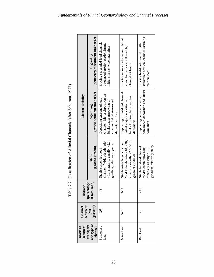
Fundamentals of Fluvial Geomorphology and Channel Processes
23
Tab
le 2
.2 C
lass
ific
atio
n of
Allu
vial
Cha
nnel
s (a
fter
Sch
umm
, 197
7)
Mod
e of
sedi
men
ttr
ansp
ort
and
type
of
chan
nel
Cha
nnel
sedi
men
t(M
)(p
erce
nt)
Bed
load
(per
cent
age
of t
otal
load
)
Cha
nnel
sta
bilit
y
Stab
le(g
rade
d st
ream
)A
ggra
ding
(exc
ess
sedi
men
t di
scha
rge)
Deg
radi
ng(d
efic
ienc
y of
sed
imen
t di
scha
rge)
Susp
ende
dlo
ad>
20<
3St
able
sus
pend
ed-l
oad
chan
nel.
Wid
th/d
epth
rat
io<1
0; s
inuo
sity
usu
ally
>2.
0;gr
adie
nt, r
elat
ivel
y ge
ntle
Dep
ositi
ng s
uspe
nded
load
chan
nel.
Maj
or d
epos
ition
on
bank
s ca
use
narr
owin
g of
chan
nel;
initi
al s
trea
mbe
dde
posi
tion
min
or
Ero
ding
sus
pend
ed-l
oad
chan
nel.
Stre
ambe
d er
osio
n pr
edom
inan
t;in
itial
cha
nnel
wid
enin
g m
inor
Mix
ed lo
ad5-
203-
11St
able
mix
ed-l
oad
chan
nel.
Wid
th/d
epth
rat
io >
10, <
40;
sinu
osity
usu
ally
<2.
0, >
1.3;
grad
ient
mod
erat
e
Dep
ositi
ng m
ixed
-loa
d ch
anne
l. In
itial
maj
or d
epos
ition
on
bank
s fo
llow
ed b
y st
ream
bed
depo
sitio
n
Ero
ding
mix
ed-l
oad
chan
nel.
Ini
tial
stre
ambe
d er
osio
n fo
llow
ed b
ych
anne
l wid
enin
g
Bed
load
<5
>11
Stab
le b
ed-l
oad
chan
nel.
Wid
th/d
epth
rat
io >
40;
sinu
osity
usu
ally
<1.
3;gr
adie
nt, r
elat
ivel
y st
eep
Dep
ositi
ng b
ed-l
oad
chan
nel.
Stre
ambe
d de
posi
tion
and
isla
ndfo
rmat
ion
Ero
ding
bed
-loa
d ch
anne
l. L
ittle
stre
ambe
d er
osio
n; c
hann
el w
iden
ing
pred
omin
ant
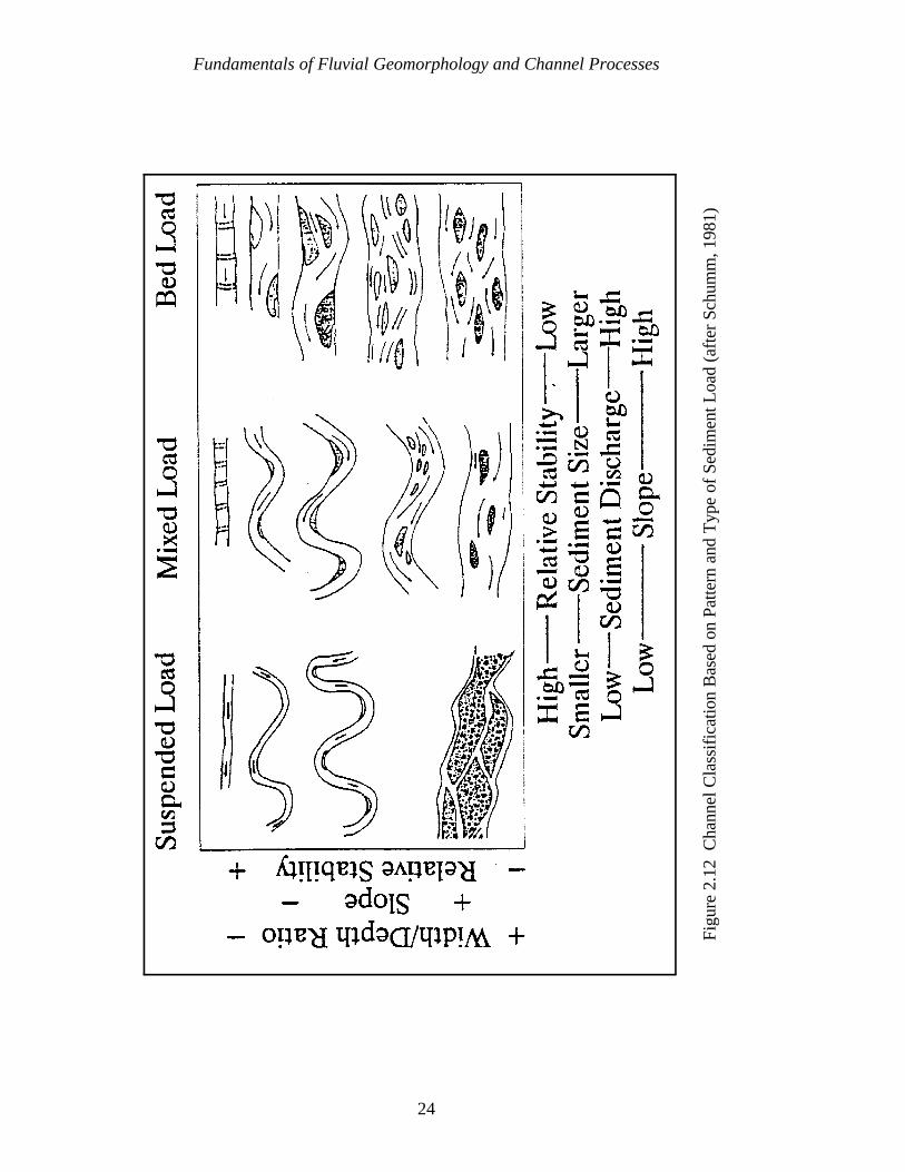
Fundamentals of Fluvial Geomorphology and Channel Processes
24
Figu
re 2
.12
Cha
nnel
Cla
ssif
icat
ion
Bas
ed o
n Pa
ttern
and
Typ
e of
Sed
imen
t Loa
d (a
fter
Sch
umm
, 198
1)
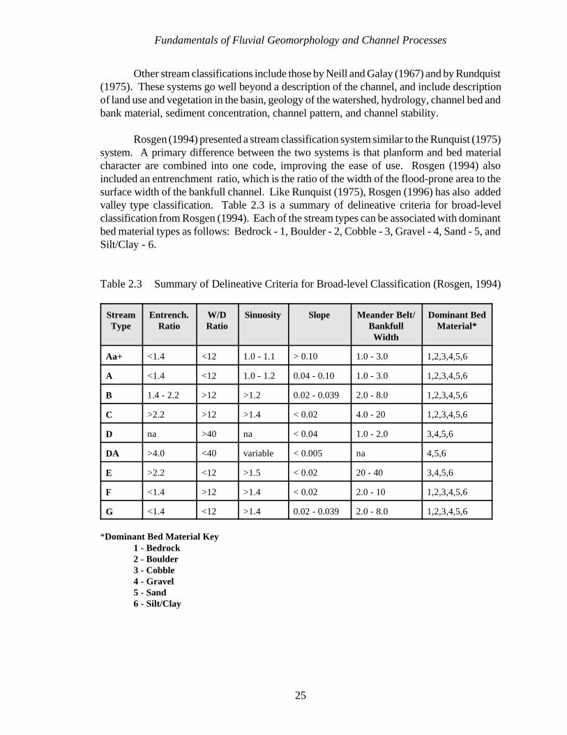
Fundamentals of Fluvial Geomorphology and Channel Processes
25
Other stream classifications include those by Neill and Galay (1967) and by Rundquist(1975). These systems go well beyond a description of the channel, and include descriptionof land use and vegetation in the basin, geology of the watershed, hydrology, channel bed andbank material, sediment concentration, channel pattern, and channel stability.
Rosgen (1994) presented a stream classification system similar to the Runquist (1975)system. A primary difference between the two systems is that planform and bed materialcharacter are combined into one code, improving the ease of use. Rosgen (1994) alsoincluded an entrenchment ratio, which is the ratio of the width of the flood-prone area to thesurface width of the bankfull channel. Like Runquist (1975), Rosgen (1996) has also addedvalley type classification. Table 2.3 is a summary of delineative criteria for broad-levelclassification from Rosgen (1994). Each of the stream types can be associated with dominantbed material types as follows: Bedrock - 1, Boulder - 2, Cobble - 3, Gravel - 4, Sand - 5, andSilt/Clay - 6.
Table 2.3 Summary of Delineative Criteria for Broad-level Classification (Rosgen, 1994)
StreamType
Entrench.Ratio
W/DRatio
Sinuosity Slope Meander Belt/Bankfull
Width
Dominant BedMaterial*
Aa+ <1.4 <12 1.0 - 1.1 > 0.10 1.0 - 3.0 1,2,3,4,5,6
A <1.4 <12 1.0 - 1.2 0.04 - 0.10 1.0 - 3.0 1,2,3,4,5,6
B 1.4 - 2.2 >12 >1.2 0.02 - 0.039 2.0 - 8.0 1,2,3,4,5,6
C >2.2 >12 >1.4 < 0.02 4.0 - 20 1,2,3,4,5,6
D na >40 na < 0.04 1.0 - 2.0 3,4,5,6
DA >4.0 <40 variable < 0.005 na 4,5,6
E >2.2 <12 >1.5 < 0.02 20 - 40 3,4,5,6
F <1.4 >12 >1.4 < 0.02 2.0 - 10 1,2,3,4,5,6
G <1.4 <12 >1.4 0.02 - 0.039 2.0 - 8.0 1,2,3,4,5,6
*Dominant Bed Material Key1 - Bedrock2 - Boulder3 - Cobble4 - Gravel5 - Sand6 - Silt/Clay

Fundamentals of Fluvial Geomorphology and Channel Processes
26
With some modifications to Figure 2.12, Figure 2.13 is a combination of someconcepts of Schumm and Rosgen. Schumm's classification system was heavily dependent onhis Midwestern experience, while Rosgen's experience began in steep mountain streams. Inaddition, Schumm's (1977) classification did not specifically include incised channels, whichare included in Rosgen's (1994) F and G classes. Figure 2.13 includes C, D, DA, and Eclasses, and could be expanded to include all of Rosgen (1994) classes. The value ofFigure 2.13 is to demonstrate that moving from class to class is a predictable response thatmanages energy, materials, and channel planform to reestablish a balance of sediment andwater discharge with sediment and water supply.
2.2 CHANNEL STABILITY CONCEPTS
Streambank protection measures often fail, not as the result of inadequate structuraldesign, but rather because of the failure of the designer to incorporate the existing and futurechannel morphology into the design. For this reason, it is important for the designer to havesome general understanding of stream processes to insure that the selected stabilizationmeasures will work in harmony with the existing and future river conditions. This sectiondescribes the basic concepts of channel stability. This will allow the designer to assesswhether the erosion at a particular site is due to local instability processes or is the result ofsome system-wide instability problems that may be affecting the entire watershed.
2.2.1 THE STABLE CHANNEL
The concept of a stable river is one that has generated controversy between engineers,scientists, landowners, and politicians for many years. An individual's definition of stabilityis often subjectively based on past experiences or project objectives. To the navigationengineer, a stable river might be one that maintains adequate depths and alignment for safenavigation. The flood control engineer on the other hand is more concerned with the channelmaintaining the ability to pass the design flood, while to the local landowner a stable river isone that does not erode the bankline. Therefore, bank erosion would not be an acceptablecomponent of these groups’ definition of a stable river. Geomorphologists and biologists, onthe other hand, might maintain that bank erosion is simply part of the natural meanderingprocess of stable rivers and would be perfectly acceptable in their definition of a stable river.Consequently, there is no universally accepted definition of a stable river. However, somemanner of defining stability is needed before the concept of instability can be discussed.Therefore, the following paragraphs will attempt to establish a definition of a stable river tobe used for this manual.
River behavior may be influenced by a number of factors. Schumm (1977) identifiedthese as independent and dependent variables. Independent variables may be thought of asthe basin inputs or constraints that cause a change in the channel morphology. Independentvariables include: basin geology, hydrology (discharge of water and sediment), valley

Fundamentals of Fluvial Geomorphology and Channel Processes
27
Figu
re 2
.13
Cha
nnel
Cla
ssif
icat
ion
Com
bini
ng A
spec
ts o
f Sc
hum
m (
1981
) an
d R
osge
n (1
994)
D 5
D 3
,4
C 4C 5
C 6
E 4
,5,6
E 5
,6
DA
5,6
Fundamentals of Fluvial Geomorphology and Channel Processes
28
dimensions (slope, width, depth), vegetation (type and density), and climate. Dependentvariables include: channel slope, depth, width, and planform.
A channel that has adjusted its dependent variables to accommodate the basin inputs(independent variables) is said to be stable. Mackin (1948) gave the following definition ofa graded stream:
A graded stream is one in which, over a period of years, slope isdelicately adjusted to provide, with available discharge and with prevailingchannel characteristics, just the velocity required for the transportation ofthe load supplied from the drainage basin. The graded stream is a systemin equilibrium.
Mackin did not say that a stream in equilibrium is unchanging and static. A more commonlyused term today for this type of stability is dynamic equilibrium. A stream in dynamicequilibrium has adjusted its width, depth and slope such that the channel is neither aggradingnor degrading. However, change may be occurring in the stream bank, erosion may result,and bank stabilization may be necessary, even on the banks of a stream in dynamicequilibrium.
The equilibrium concept of streams discussed above can also be described by variousqualitative relationships. One of the most widely used relationships is the one proposed byLane (1955) which states that:
QS % QsD50
where Q is the water discharge, S is the slope, Qs is the bed material load, and D50 is themedian size of the bed material. This relationship, commonly referred to as Lane's Balance,is illustrated in Figure 2.14. Mackin's concept of adjustment to changes in the controllingvariables is easily illustrated by Lane's balance (Figure 2.14) which shows that a change in anyof the four variables will cause a change in the others such that equilibrium is restored. Whena channel is in equilibrium, it will have adjusted these four variables such that the sedimentbeing transported into the reach is transported out, without significant deposition of sedimentin the bed (aggradation), or excessive bed scour (degradation). It should be noted that bythis definition of stability, a channel is free to migrate laterally by eroding one of its banks andaccreting the one opposite at a similar rate.
Meandering can be thought of as nature's way of adjusting its energy (slope) to thevariable inputs of water and sediment. Cutoffs (oxbow lakes) and abandoned courses in thefloodplain attest to the dynamic behavior of rivers. Oftentimes the engineer or scientist drawsthe erroneous conclusion that a dis-equilibrium condition exist because natural cutoffs areoccurring. However, this type of dynamic behavior is quite common in rivers that are in astate of dynamic equilibrium. In this situation, as natural cutoffs occur, the river may be

Fundamentals of Fluvial Geomorphology and Channel Processes
29
Figure 2.14 Lane’s Balance (after E. W. Lane, from W. Borland)
obtaining additional length elsewhere through meandering, with the net result being that theoverall reach length, and therefore slope, remains unchanged.
In summary, a stable river, from a geomorphic perspective, is one that has adjustedits width, depth, and slope such that there is no significant aggradation or degradation of thestream bed or significant plan form changes (meandering to braided, etc.) within theengineering time frame (generally less than about 50 years). By this definition, a stable riveris not in a static condition, but rather is in a state of dynamic equilibrium where it is free toadjust laterally through bank erosion and bar building. This geomorphic definition of stability(dynamic equilibrium) is developed here to establish a reference point for the discussion ofsystem and local instability in the following sections.
2.2.2 SYSTEM INSTABILITY
The equilibrium of a river system can be disrupted by various factors. Once this occursthe channel will attempt to re-gain equilibrium by making adjustments in the dependent varia-bles. These adjustments are generally reflected in channel aggradation (increasing bedelevation), degradation (decreasing bed elevation), or changes in planform characteristics
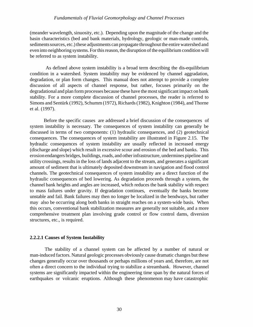
Fundamentals of Fluvial Geomorphology and Channel Processes
30
(meander wavelength, sinuosity, etc.). Depending upon the magnitude of the change and thebasin characteristics (bed and bank materials, hydrology, geologic or man-made controls,sediments sources, etc.) these adjustments can propagate throughout the entire watershed andeven into neighboring systems. For this reason, the disruption of the equilibrium condition willbe referred to as system instability.
As defined above system instability is a broad term describing the dis-equilibriumcondition in a watershed. System instability may be evidenced by channel aggradation,degradation, or plan form changes. This manual does not attempt to provide a completediscussion of all aspects of channel response, but rather, focuses primarily on thedegradational and plan form processes because these have the most significant impact on bankstability. For a more complete discussion of channel processes, the reader is referred toSimons and Sentürk (1992), Schumm (1972), Richards (1982), Knighton (1984), and Thorneet al. (1997). Before the specific causes are addressed a brief discussion of the consequences ofsystem instability is necessary. The consequences of system instability can generally bediscussed in terms of two components: (1) hydraulic consequences, and (2) geotechnicalconsequences. The consequences of system instability are illustrated in Figure 2.15. Thehydraulic consequences of system instability are usually reflected in increased energy(discharge and slope) which result in excessive scour and erosion of the bed and banks. Thiserosion endangers bridges, buildings, roads, and other infrastructure, undermines pipeline andutility crossings, results in the loss of lands adjacent to the stream, and generates a significantamount of sediment that is ultimately deposited downstream in navigation and flood controlchannels. The geotechnical consequences of system instability are a direct function of thehydraulic consequences of bed lowering. As degradation proceeds through a system, thechannel bank heights and angles are increased, which reduces the bank stability with respectto mass failures under gravity. If degradation continues, eventually the banks becomeunstable and fail. Bank failures may then no longer be localized in the bendways, but rathermay also be occurring along both banks in straight reaches on a system-wide basis. Whenthis occurs, conventional bank stabilization measures are generally not suitable, and a morecomprehensive treatment plan involving grade control or flow control dams, diversionstructures, etc., is required.
2.2.2.1 Causes of System Instability
The stability of a channel system can be affected by a number of natural orman-induced factors. Natural geologic processes obviously cause dramatic changes but thesechanges generally occur over thousands or perhaps millions of years and, therefore, are notoften a direct concern to the individual trying to stabilize a streambank. However, channelsystems are significantly impacted within the engineering time span by the natural forces ofearthquakes or volcanic eruptions. Although these phenomenon may have catastrophic
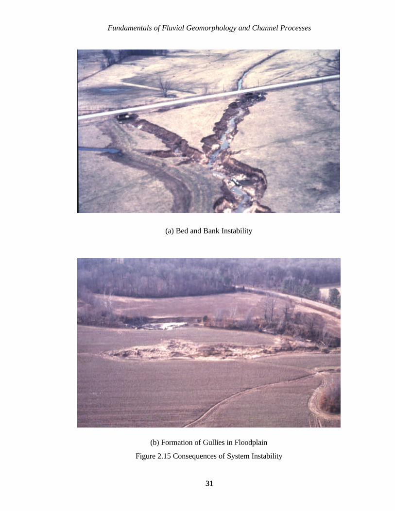
Fundamentals of Fluvial Geomorphology and Channel Processes
3131
(a) Bed and Bank Instability
(b) Formation of Gullies in Floodplain
Figure 2.15 Consequences of System Instability
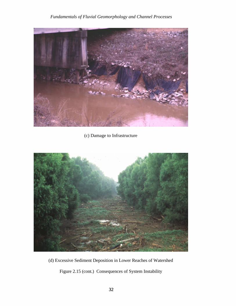
Fundamentals of Fluvial Geomorphology and Channel Processes
3232
(c) Damage to Infrastructure
(d) Excessive Sediment Deposition in Lower Reaches of Watershed
Figure 2.15 (cont.) Consequences of System Instability
Fundamentals of Fluvial Geomorphology and Channel Processes
3333
consequences and receive considerable media attention, the most commonly encounteredsystem instability problems can generally be attributed, at least in part, to man's activities.
Any time one or more of the controlling variables (runoff, sediment loads, sedimentsize, channel slope, etc.) in a watershed are altered there is a potential for inducing systeminstability. The particular system response will reflect the magnitude of change and theexisting morphological sensitivity of the system. Therefore, each system is unique and thereis no standard response that applies to all situations. With this in mind it is not practical toattempt to discuss all the possible scenarios of channel response. Rather, the aim of thisdiscussion is to present some of the more common factors causing system instability, and toillustrate how a particular channel response might be anticipated using the stability conceptsdiscussed earlier.
A list and brief discussion of some of the more common causes of system instability arepresented in the following sections. For this discussion the causes have been grouped intothree categories: (1) downstream factors, (2) upstream factors, and (3) basin-wide factors.Following this, a brief discussion is presented concerning complex response and thecomplications involved when a system is subjected to multiple factors.
Downstream Factors. The stability of a channel system can be significantly affectedby a downstream base level lowering. Base level refers to the downstream controlling watersurface or bed elevation for a stream. One of the most common causes of base level loweringis the implementation of cutoffs or channelization as part of channel improvement projects(Figure 2.16). As indicated by Lane's relation (Figure 2.14) the increased slope must be offsetby one of the other variables. Consequently, there is an imbalance between the sedimenttransport capacity and supply. If the discharge and bed material are assumed to remainconstant (which may not always be the case), then the channel must adjust to the increasedslope (i.e., sediment transport capacity) by increasing its bed material load. This increasedsediment load will be derived from the bed and banks of the channel in the form of channeldegradation and bank erosion. As the bed continues to degrade the zone of increased slopewill migrate upstream and the increased bed material load is transmitted downstream to driveaggradational instability there.
The manner in which degradation migrates through a channel system is a very complexprocess. Before this process is discussed some of the relevant terminology must first beaddressed. The following definition of terms is based on the terminology used by Schummet al. (1984). Channel degradation simply refers to the lowering of the channel bed. Fieldindicators of degradation occur in the form of knickpoints or knickzones. A knickpointis a location on the thalweg of an abrupt change of elevation and slope (Figure 2.17). Thismay also be visualized as a waterfall or vertical discontinuity in the stream bed. A steep reachof channel representing the headward migrating zone is referred to as a knickzone (Figure2.18). A knickzone is often composed of a series of small knickpoints. Knickpoints andknickzones are often referred to as headcuts. While headcut is a commonly used term, it doesgenerate some confusion because it is also used as a description of the headward migrationprocess of degradation.
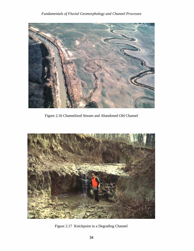
Fundamentals of Fluvial Geomorphology and Channel Processes
3434
Figure 2.16 Channelized Stream and Abandoned Old Channel
Figure 2.17 Knickpoint in a Degrading Channel
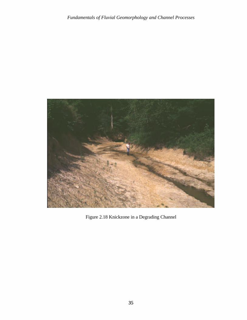
Fundamentals of Fluvial Geomorphology and Channel Processes
3535
Figure 2.18 Knickzone in a Degrading Channel
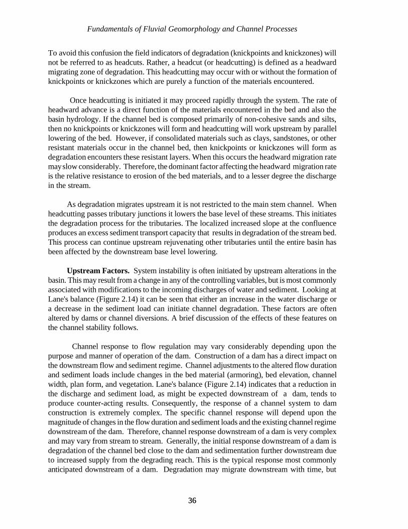
Fundamentals of Fluvial Geomorphology and Channel Processes
3636
To avoid this confusion the field indicators of degradation (knickpoints and knickzones) willnot be referred to as headcuts. Rather, a headcut (or headcutting) is defined as a headwardmigrating zone of degradation. This headcutting may occur with or without the formation ofknickpoints or knickzones which are purely a function of the materials encountered.
Once headcutting is initiated it may proceed rapidly through the system. The rate ofheadward advance is a direct function of the materials encountered in the bed and also thebasin hydrology. If the channel bed is composed primarily of non-cohesive sands and silts,then no knickpoints or knickzones will form and headcutting will work upstream by parallellowering of the bed. However, if consolidated materials such as clays, sandstones, or otherresistant materials occur in the channel bed, then knickpoints or knickzones will form asdegradation encounters these resistant layers. When this occurs the headward migration ratemay slow considerably. Therefore, the dominant factor affecting the headward migration rateis the relative resistance to erosion of the bed materials, and to a lesser degree the dischargein the stream.
As degradation migrates upstream it is not restricted to the main stem channel. Whenheadcutting passes tributary junctions it lowers the base level of these streams. This initiatesthe degradation process for the tributaries. The localized increased slope at the confluenceproduces an excess sediment transport capacity that results in degradation of the stream bed.This process can continue upstream rejuvenating other tributaries until the entire basin hasbeen affected by the downstream base level lowering.
Upstream Factors. System instability is often initiated by upstream alterations in thebasin. This may result from a change in any of the controlling variables, but is most commonlyassociated with modifications to the incoming discharges of water and sediment. Looking atLane's balance (Figure 2.14) it can be seen that either an increase in the water discharge ora decrease in the sediment load can initiate channel degradation. These factors are oftenaltered by dams or channel diversions. A brief discussion of the effects of these features onthe channel stability follows.
Channel response to flow regulation may vary considerably depending upon thepurpose and manner of operation of the dam. Construction of a dam has a direct impact onthe downstream flow and sediment regime. Channel adjustments to the altered flow durationand sediment loads include changes in the bed material (armoring), bed elevation, channelwidth, plan form, and vegetation. Lane's balance (Figure 2.14) indicates that a reduction inthe discharge and sediment load, as might be expected downstream of a dam, tends toproduce counter-acting results. Consequently, the response of a channel system to damconstruction is extremely complex. The specific channel response will depend upon themagnitude of changes in the flow duration and sediment loads and the existing channel regimedownstream of the dam. Therefore, channel response downstream of a dam is very complexand may vary from stream to stream. Generally, the initial response downstream of a dam isdegradation of the channel bed close to the dam and sedimentation further downstream dueto increased supply from the degrading reach. This is the typical response most commonlyanticipated downstream of a dam. Degradation may migrate downstream with time, but
Fundamentals of Fluvial Geomorphology and Channel Processes
3737
Q 'b d L
S
generally it is most significant during the first few years following closure of the dam. Insome situations, a channel may shift from a degradational to an aggradational phase inresponse to slope flattening due to degradation, increased sediment inputs from tributaries andbed and bank erosion, and reduction in the dominant discharge.
System instability can also be introduced by the diversion of water into or out of thestream. Channel diversion structures are designed to divert a portion of the water and/orsediment from a stream and deliver it to another location. Diversions are often needed forwater supply, irrigation, hydropower, flood control, or environmental reasons. The systemeffects and complexities are similar to those downstream of major dams. According to Lane'sbalance the sediment load in the receiving stream will be increased due to extra, transportcapacity of the increased discharge. In time, the erosion of bed sediments decreases as theslope is reduced through bed degradation.
An increase in discharge due to a flow diversion can have a significant impact on thechannel plan form as well as the vertical stability. Schumm (1977) proposed a qualitativerelation similar to Lane's that included meander wavelength. His relation states that:
where Q is the discharge, b is the width, d is the depth, S is the slope, and L is the meanderwavelength. The above relation indicates that an increase in discharge may result in anincrease in the meander wavelength which would be accomplished through acceleratederosion of the streambanks. Therefore, whenever diversions such as this are proposed thepotential for increased meander activity must be considered. If a stream is in the process ofincreasing meander wavelength, then stabilization of the bends along the existing alignmentis likely to be unsuccessful and is not recommended.
Basin Wide Factors. Sometimes the changes in the controlling variables can not beattributed to a specific upstream or downstream factor, but rather are occurring on abasin-wide basis. This often results from a major land use change or urbanization. Thesechanges can significantly modify the incoming discharge and sediment loads to a channelsystem. For example, urbanization can increase peak flows and reduce sediment delivery, bothof which would tend to cause channel degradation in the channel system. A land use changefrom forest to row crop on the other hand might cause a significant increase in the sedimentloading resulting in aggradation of the channel system. Unfortunately, it is difficult, if notimpossible, to predict when basin wide changes such as these will occur. Therefore, the bestthe designer can do in most cases is to simply try to design the bank protection measures toaccommodate the most likely future changes in the watershed. For instance, if there is apossibility of future urbanization in the upper watershed, then additional launching stone maybe needed to protect the bank from the destabilizing impact of any future bed lowering.
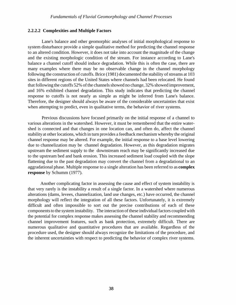
Fundamentals of Fluvial Geomorphology and Channel Processes
3838
2.2.2.2 Complexities and Multiple Factors
Lane's balance and other geomorphic analyses of initial morphological response tosystem disturbance provide a simple qualitative method for predicting the channel responseto an altered condition. However, it does not take into account the magnitude of the changeand the existing morphologic condition of the stream. For instance according to Lane'sbalance a channel cutoff should induce degradation. While this is often the case, there aremany examples where there may be no observable change in the channel morphologyfollowing the construction of cutoffs. Brice (1981) documented the stability of streams at 103sites in different regions of the United States where channels had been relocated. He foundthat following the cutoffs 52% of the channels showed no change, 32% showed improvement,and 16% exhibited channel degradation. This study indicates that predicting the channelresponse to cutoffs is not nearly as simple as might be inferred from Lane's balance.Therefore, the designer should always be aware of the considerable uncertainties that existwhen attempting to predict, even in qualitative terms, the behavior of river systems.
Previous discussions have focused primarily on the initial response of a channel tovarious alterations in the watershed. However, it must be remembered that the entire water-shed is connected and that changes in one location can, and often do, affect the channelstability at other locations, which in turn provides a feedback mechanism whereby the originalchannel response may be altered. For example, the initial response to a base level loweringdue to channelization may be channel degradation. However, as this degradation migratesupstream the sediment supply to the downstream reach may be significantly increased dueto the upstream bed and bank erosion. This increased sediment load coupled with the slopeflattening due to the past degradation may convert the channel from a degradational to anaggradational phase. Multiple response to a single alteration has been referred to as complexresponse by Schumm (1977).
Another complicating factor in assessing the cause and effect of system instability isthat very rarely is the instability a result of a single factor. In a watershed where numerousalterations (dams, levees, channelization, land use changes, etc.) have occurred, the channelmorphology will reflect the integration of all these factors. Unfortunately, it is extremelydifficult and often impossible to sort out the precise contributions of each of thesecomponents to the system instability. The interaction of these individual factors coupled withthe potential for complex response makes assessing the channel stability and recommendingchannel improvement features, such as bank protection, extremely difficult. There arenumerous qualitative and quantitative procedures that are available. Regardless of theprocedure used, the designer should always recognize the limitations of the procedure, andthe inherent uncertainties with respect to predicting the behavior of complex river systems.
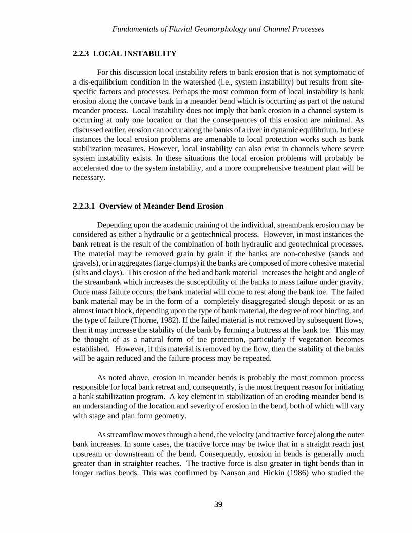
Fundamentals of Fluvial Geomorphology and Channel Processes
3939
2.2.3 LOCAL INSTABILITY
For this discussion local instability refers to bank erosion that is not symptomatic ofa dis-equilibrium condition in the watershed (i.e., system instability) but results from site-specific factors and processes. Perhaps the most common form of local instability is bankerosion along the concave bank in a meander bend which is occurring as part of the naturalmeander process. Local instability does not imply that bank erosion in a channel system isoccurring at only one location or that the consequences of this erosion are minimal. Asdiscussed earlier, erosion can occur along the banks of a river in dynamic equilibrium. In theseinstances the local erosion problems are amenable to local protection works such as bankstabilization measures. However, local instability can also exist in channels where severesystem instability exists. In these situations the local erosion problems will probably beaccelerated due to the system instability, and a more comprehensive treatment plan will benecessary.
2.2.3.1 Overview of Meander Bend Erosion
Depending upon the academic training of the individual, streambank erosion may beconsidered as either a hydraulic or a geotechnical process. However, in most instances thebank retreat is the result of the combination of both hydraulic and geotechnical processes.The material may be removed grain by grain if the banks are non-cohesive (sands andgravels), or in aggregates (large clumps) if the banks are composed of more cohesive material(silts and clays). This erosion of the bed and bank material increases the height and angle ofthe streambank which increases the susceptibility of the banks to mass failure under gravity.Once mass failure occurs, the bank material will come to rest along the bank toe. The failedbank material may be in the form of a completely disaggregated slough deposit or as analmost intact block, depending upon the type of bank material, the degree of root binding, andthe type of failure (Thorne, 1982). If the failed material is not removed by subsequent flows,then it may increase the stability of the bank by forming a buttress at the bank toe. This maybe thought of as a natural form of toe protection, particularly if vegetation becomesestablished. However, if this material is removed by the flow, then the stability of the bankswill be again reduced and the failure process may be repeated.
As noted above, erosion in meander bends is probably the most common processresponsible for local bank retreat and, consequently, is the most frequent reason for initiatinga bank stabilization program. A key element in stabilization of an eroding meander bend isan understanding of the location and severity of erosion in the bend, both of which will varywith stage and plan form geometry.
As streamflow moves through a bend, the velocity (and tractive force) along the outerbank increases. In some cases, the tractive force may be twice that in a straight reach justupstream or downstream of the bend. Consequently, erosion in bends is generally muchgreater than in straighter reaches. The tractive force is also greater in tight bends than inlonger radius bends. This was confirmed by Nanson and Hickin (1986) who studied the
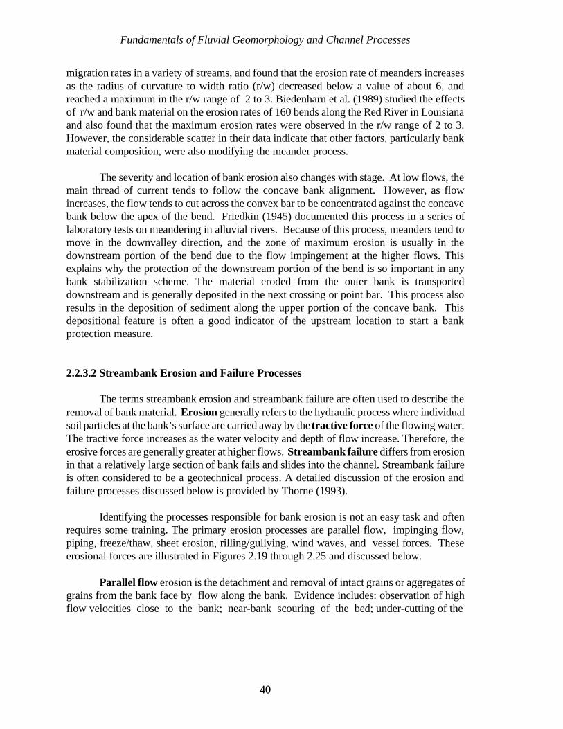
Fundamentals of Fluvial Geomorphology and Channel Processes
4040
migration rates in a variety of streams, and found that the erosion rate of meanders increasesas the radius of curvature to width ratio (r/w) decreased below a value of about 6, andreached a maximum in the r/w range of 2 to 3. Biedenharn et al. (1989) studied the effectsof r/w and bank material on the erosion rates of 160 bends along the Red River in Louisianaand also found that the maximum erosion rates were observed in the r/w range of 2 to 3.However, the considerable scatter in their data indicate that other factors, particularly bankmaterial composition, were also modifying the meander process.
The severity and location of bank erosion also changes with stage. At low flows, themain thread of current tends to follow the concave bank alignment. However, as flowincreases, the flow tends to cut across the convex bar to be concentrated against the concavebank below the apex of the bend. Friedkin (1945) documented this process in a series oflaboratory tests on meandering in alluvial rivers. Because of this process, meanders tend tomove in the downvalley direction, and the zone of maximum erosion is usually in thedownstream portion of the bend due to the flow impingement at the higher flows. Thisexplains why the protection of the downstream portion of the bend is so important in anybank stabilization scheme. The material eroded from the outer bank is transporteddownstream and is generally deposited in the next crossing or point bar. This process alsoresults in the deposition of sediment along the upper portion of the concave bank. Thisdepositional feature is often a good indicator of the upstream location to start a bankprotection measure.
2.2.3.2 Streambank Erosion and Failure Processes
The terms streambank erosion and streambank failure are often used to describe theremoval of bank material. Erosion generally refers to the hydraulic process where individualsoil particles at the bank’s surface are carried away by the tractive force of the flowing water.The tractive force increases as the water velocity and depth of flow increase. Therefore, theerosive forces are generally greater at higher flows. Streambank failure differs from erosionin that a relatively large section of bank fails and slides into the channel. Streambank failureis often considered to be a geotechnical process. A detailed discussion of the erosion andfailure processes discussed below is provided by Thorne (1993).
Identifying the processes responsible for bank erosion is not an easy task and oftenrequires some training. The primary erosion processes are parallel flow, impinging flow,piping, freeze/thaw, sheet erosion, rilling/gullying, wind waves, and vessel forces. Theseerosional forces are illustrated in Figures 2.19 through 2.25 and discussed below.
Parallel flow erosion is the detachment and removal of intact grains or aggregates ofgrains from the bank face by flow along the bank. Evidence includes: observation of highflow velocities close to the bank; near-bank scouring of the bed; under-cutting of the
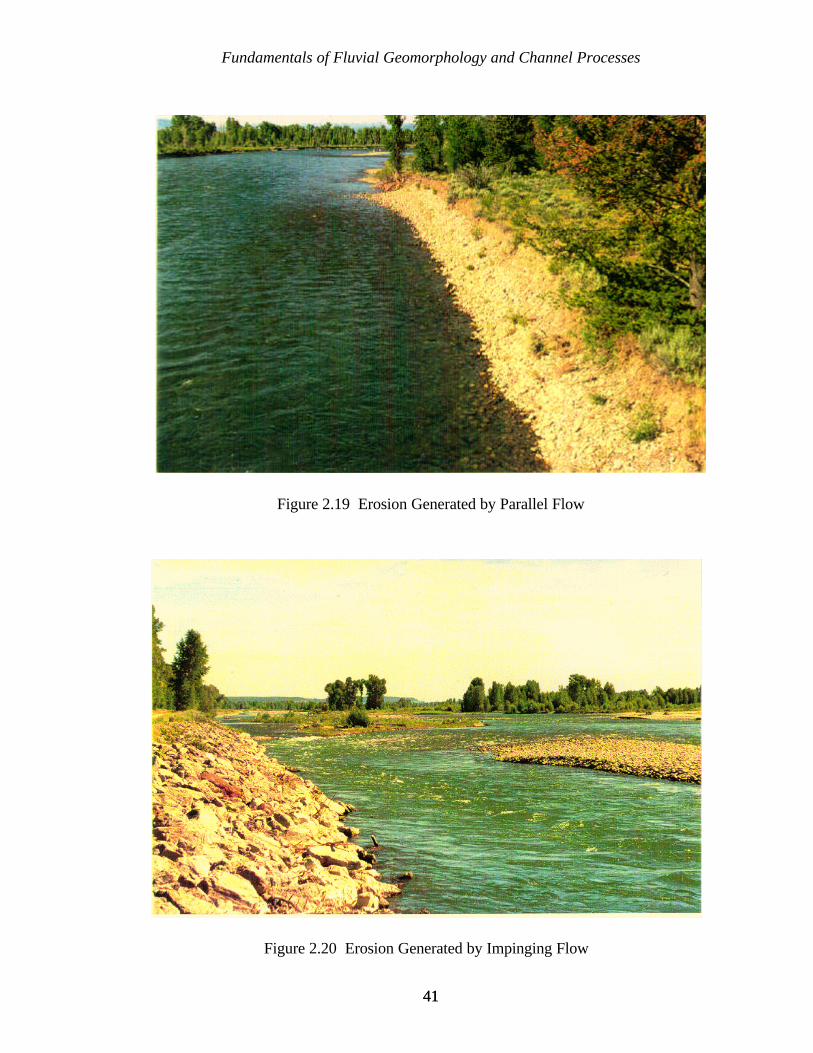
Fundamentals of Fluvial Geomorphology and Channel Processes
4141
Figure 2.19 Erosion Generated by Parallel Flow
Figure 2.20 Erosion Generated by Impinging Flow

Fundamentals of Fluvial Geomorphology and Channel Processes
4242
Figure 2.21 Erosion Generated by Piping
Figure 2.22 Erosion Generated by Freeze/Thaw

Fundamentals of Fluvial Geomorphology and Channel Processes
4343
Figure 2.24 Erosion Generated by Wind Waves
Figure 2.23 Sheet Erosion with Rilling and Gullying
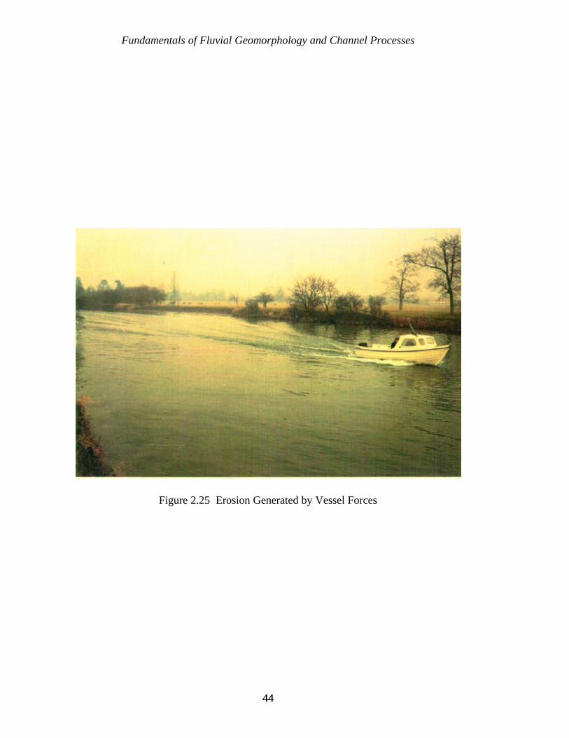
Fundamentals of Fluvial Geomorphology and Channel Processes
4444
Figure 2.25 Erosion Generated by Vessel Forces
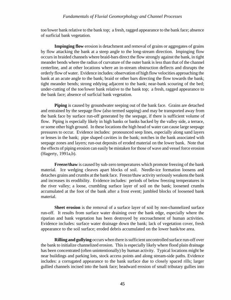
Fundamentals of Fluvial Geomorphology and Channel Processes
4545
toe/lower bank relative to the bank top; a fresh, ragged appearance to the bank face; absenceof surficial bank vegetation.
Impinging flow erosion is detachment and removal of grains or aggregates of grainsby flow attacking the bank at a steep angle to the long-stream direction. Impinging flowoccurs in braided channels where braid-bars direct the flow strongly against the bank, in tightmeander bends where the radius of curvature of the outer bank is less than that of the channelcenterline, and at other locations where an in-stream obstruction deflects and disrupts theorderly flow of water. Evidence includes: observation of high flow velocities approaching thebank at an acute angle to the bank; braid or other bars directing the flow towards the bank;tight meander bends; strong eddying adjacent to the bank; near-bank scouring of the bed;under-cutting of the toe/lower bank relative to the bank top; a fresh, ragged appearance tothe bank face; absence of surficial bank vegetation.
Piping is caused by groundwater seeping out of the bank face. Grains are detachedand entrained by the seepage flow (also termed sapping) and may be transported away fromthe bank face by surface run-off generated by the seepage, if there is sufficient volume offlow. Piping is especially likely in high banks or banks backed by the valley side, a terrace,or some other high ground. In these locations the high head of water can cause large seepagepressures to occur. Evidence includes: pronounced seep lines, especially along sand layersor lenses in the bank; pipe shaped cavities in the bank; notches in the bank associated withseepage zones and layers; run-out deposits of eroded material on the lower bank. Note thatthe effects of piping erosion can easily be mistaken for those of wave and vessel force erosion(Hagerty, 1991a,b).
Freeze/thaw is caused by sub-zero temperatures which promote freezing of the bankmaterial. Ice wedging cleaves apart blocks of soil. Needle-ice formation loosens anddetaches grains and crumbs at the bank face. Freeze/thaw activity seriously weakens the bankand increases its erodibility. Evidence includes: periods of below freezing temperatures inthe river valley; a loose, crumbling surface layer of soil on the bank; loosened crumbsaccumulated at the foot of the bank after a frost event; jumbled blocks of loosened bankmaterial.
Sheet erosion is the removal of a surface layer of soil by non-channelized surfacerun-off. It results from surface water draining over the bank edge, especially where theriparian and bank vegetation has been destroyed by encroachment of human activities.Evidence includes: surface water drainage down the bank; lack of vegetation cover, freshappearance to the soil surface; eroded debris accumulated on the lower bank/toe area.
Rilling and gullying occurs when there is sufficient uncontrolled surface run-off overthe bank to initialize channelized erosion. This is especially likely where flood plain drainagehas been concentrated (often unintentionally) by human activity. Typical locations might benear buildings and parking lots, stock access points and along stream-side paths. Evidenceincludes: a corrugated appearance to the bank surface due to closely spaced rills; largergullied channels incised into the bank face; headward erosion of small tributary gullies into
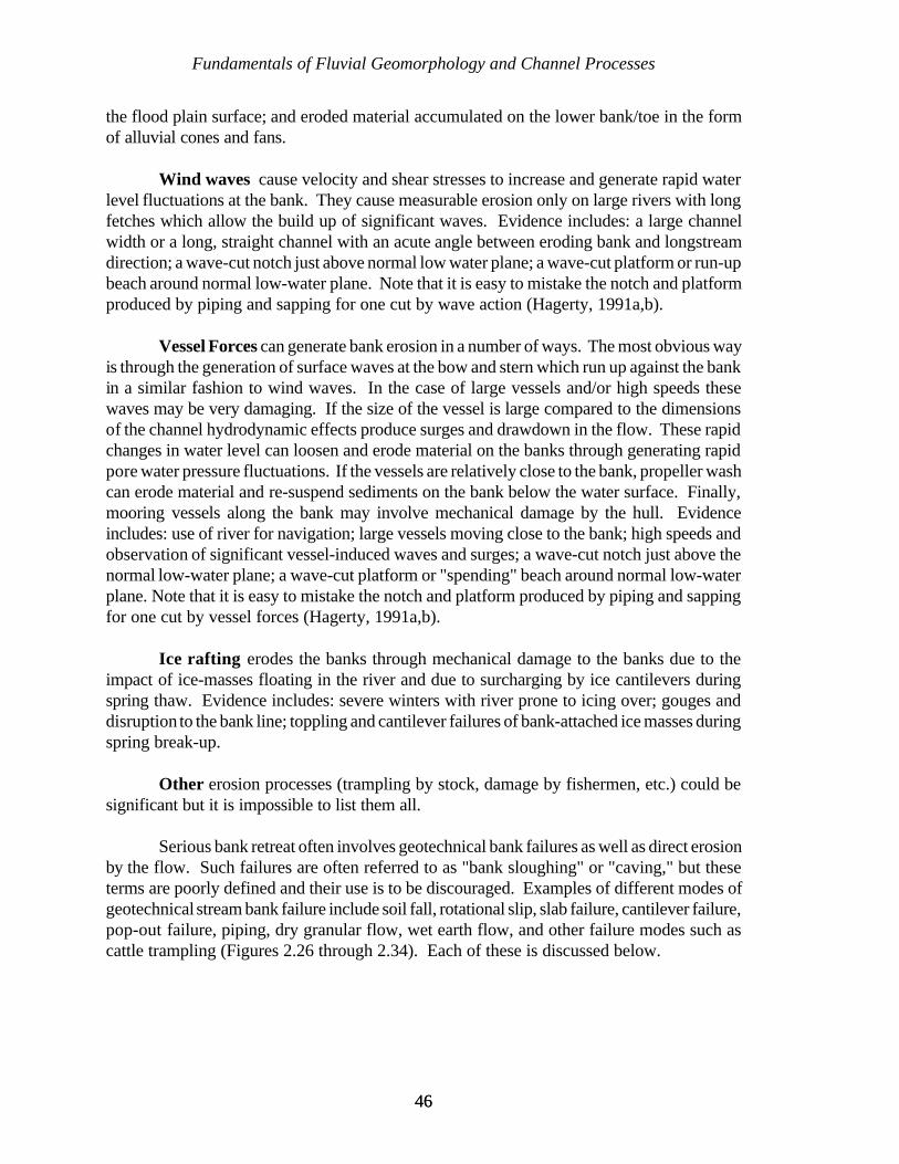
Fundamentals of Fluvial Geomorphology and Channel Processes
4646
the flood plain surface; and eroded material accumulated on the lower bank/toe in the formof alluvial cones and fans.
Wind waves cause velocity and shear stresses to increase and generate rapid waterlevel fluctuations at the bank. They cause measurable erosion only on large rivers with longfetches which allow the build up of significant waves. Evidence includes: a large channelwidth or a long, straight channel with an acute angle between eroding bank and longstreamdirection; a wave-cut notch just above normal low water plane; a wave-cut platform or run-upbeach around normal low-water plane. Note that it is easy to mistake the notch and platformproduced by piping and sapping for one cut by wave action (Hagerty, 1991a,b).
Vessel Forces can generate bank erosion in a number of ways. The most obvious wayis through the generation of surface waves at the bow and stern which run up against the bankin a similar fashion to wind waves. In the case of large vessels and/or high speeds thesewaves may be very damaging. If the size of the vessel is large compared to the dimensionsof the channel hydrodynamic effects produce surges and drawdown in the flow. These rapidchanges in water level can loosen and erode material on the banks through generating rapidpore water pressure fluctuations. If the vessels are relatively close to the bank, propeller washcan erode material and re-suspend sediments on the bank below the water surface. Finally,mooring vessels along the bank may involve mechanical damage by the hull. Evidenceincludes: use of river for navigation; large vessels moving close to the bank; high speeds andobservation of significant vessel-induced waves and surges; a wave-cut notch just above thenormal low-water plane; a wave-cut platform or "spending" beach around normal low-waterplane. Note that it is easy to mistake the notch and platform produced by piping and sappingfor one cut by vessel forces (Hagerty, 1991a,b).
Ice rafting erodes the banks through mechanical damage to the banks due to theimpact of ice-masses floating in the river and due to surcharging by ice cantilevers duringspring thaw. Evidence includes: severe winters with river prone to icing over; gouges anddisruption to the bank line; toppling and cantilever failures of bank-attached ice masses duringspring break-up.
Other erosion processes (trampling by stock, damage by fishermen, etc.) could besignificant but it is impossible to list them all.
Serious bank retreat often involves geotechnical bank failures as well as direct erosionby the flow. Such failures are often referred to as "bank sloughing" or "caving," but theseterms are poorly defined and their use is to be discouraged. Examples of different modes ofgeotechnical stream bank failure include soil fall, rotational slip, slab failure, cantilever failure,pop-out failure, piping, dry granular flow, wet earth flow, and other failure modes such ascattle trampling (Figures 2.26 through 2.34). Each of these is discussed below.
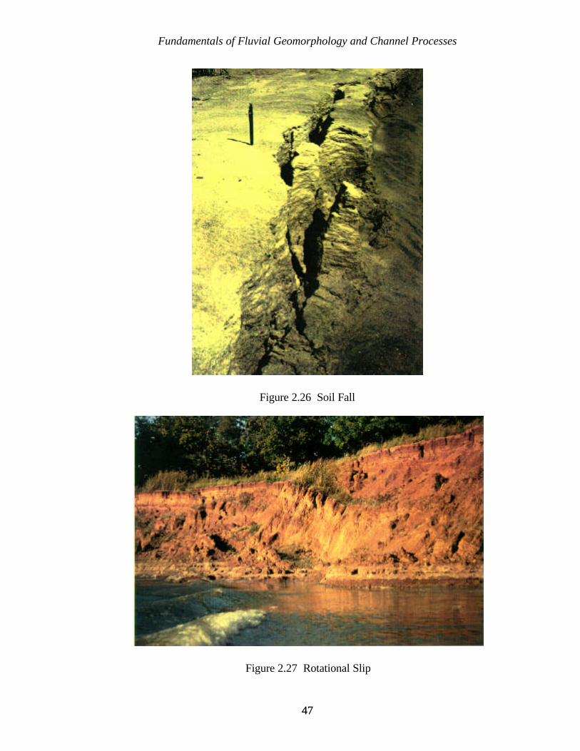
Fundamentals of Fluvial Geomorphology and Channel Processes
4747
Figure 2.26 Soil Fall
Figure 2.27 Rotational Slip
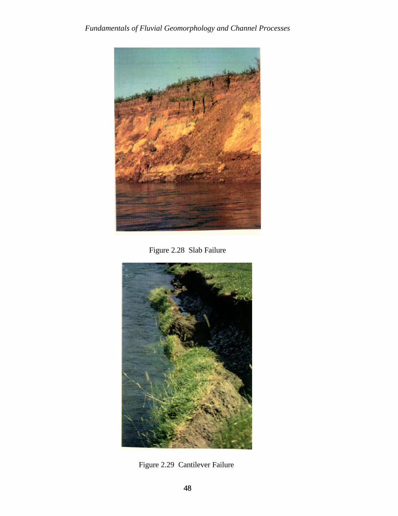
Fundamentals of Fluvial Geomorphology and Channel Processes
4848
Figure 2.28 Slab Failure
Figure 2.29 Cantilever Failure
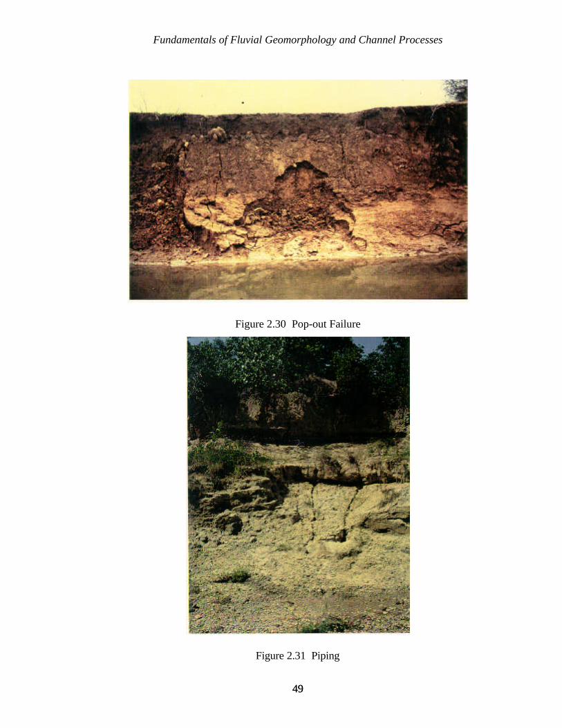
Fundamentals of Fluvial Geomorphology and Channel Processes
4949
Figure 2.30 Pop-out Failure
Figure 2.31 Piping

Fundamentals of Fluvial Geomorphology and Channel Processes
5050
Figure 2.32 Dry Granular Flow
Figure 2.33 Wet Earth Flow
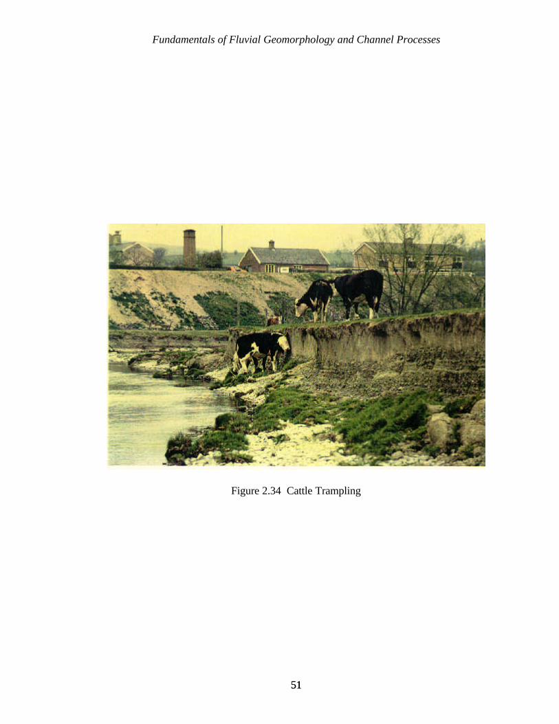
Fundamentals of Fluvial Geomorphology and Channel Processes
5151
Figure 2.34 Cattle Trampling
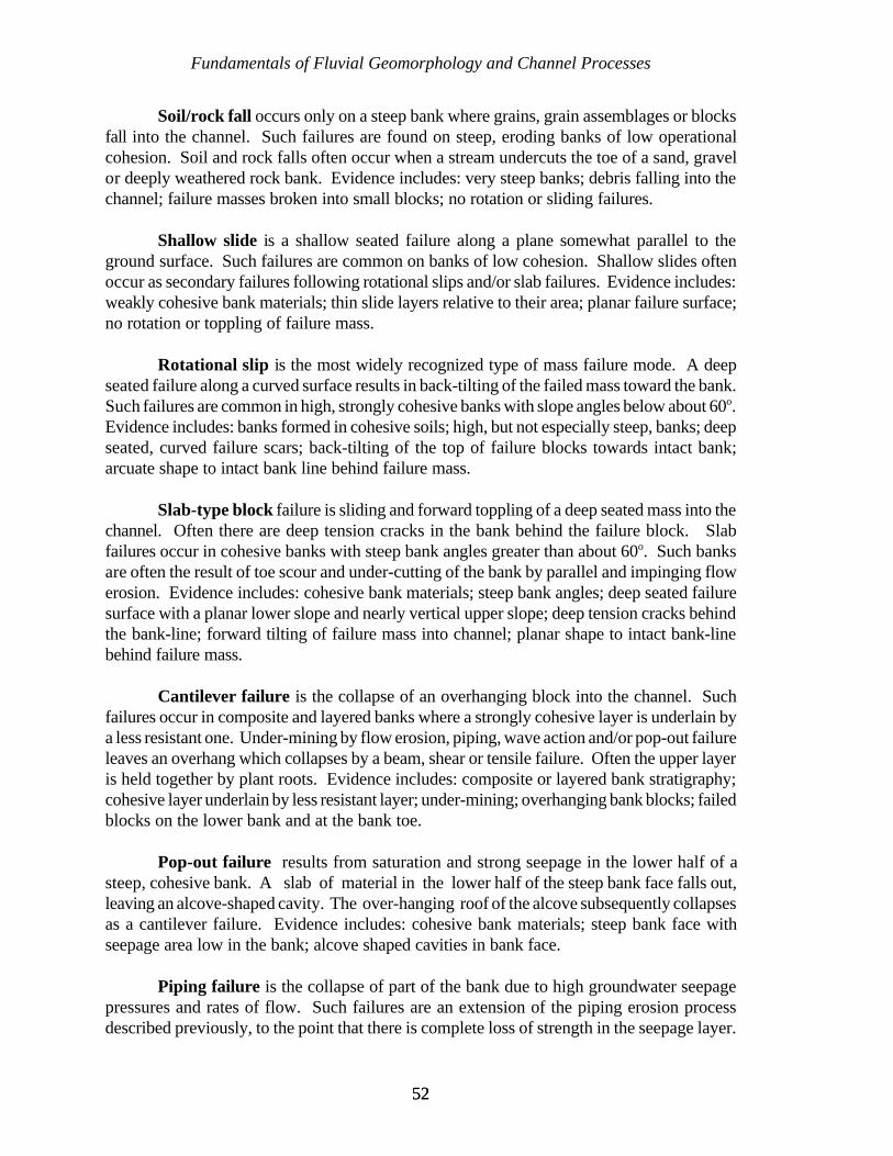
Fundamentals of Fluvial Geomorphology and Channel Processes
5252
Soil/rock fall occurs only on a steep bank where grains, grain assemblages or blocksfall into the channel. Such failures are found on steep, eroding banks of low operationalcohesion. Soil and rock falls often occur when a stream undercuts the toe of a sand, gravelor deeply weathered rock bank. Evidence includes: very steep banks; debris falling into thechannel; failure masses broken into small blocks; no rotation or sliding failures.
Shallow slide is a shallow seated failure along a plane somewhat parallel to theground surface. Such failures are common on banks of low cohesion. Shallow slides oftenoccur as secondary failures following rotational slips and/or slab failures. Evidence includes:weakly cohesive bank materials; thin slide layers relative to their area; planar failure surface;no rotation or toppling of failure mass.
Rotational slip is the most widely recognized type of mass failure mode. A deepseated failure along a curved surface results in back-tilting of the failed mass toward the bank.Such failures are common in high, strongly cohesive banks with slope angles below about 60o.Evidence includes: banks formed in cohesive soils; high, but not especially steep, banks; deepseated, curved failure scars; back-tilting of the top of failure blocks towards intact bank;arcuate shape to intact bank line behind failure mass.
Slab-type block failure is sliding and forward toppling of a deep seated mass into thechannel. Often there are deep tension cracks in the bank behind the failure block. Slabfailures occur in cohesive banks with steep bank angles greater than about 60o. Such banksare often the result of toe scour and under-cutting of the bank by parallel and impinging flowerosion. Evidence includes: cohesive bank materials; steep bank angles; deep seated failuresurface with a planar lower slope and nearly vertical upper slope; deep tension cracks behindthe bank-line; forward tilting of failure mass into channel; planar shape to intact bank-linebehind failure mass.
Cantilever failure is the collapse of an overhanging block into the channel. Suchfailures occur in composite and layered banks where a strongly cohesive layer is underlain bya less resistant one. Under-mining by flow erosion, piping, wave action and/or pop-out failureleaves an overhang which collapses by a beam, shear or tensile failure. Often the upper layeris held together by plant roots. Evidence includes: composite or layered bank stratigraphy;cohesive layer underlain by less resistant layer; under-mining; overhanging bank blocks; failedblocks on the lower bank and at the bank toe.
Pop-out failure results from saturation and strong seepage in the lower half of asteep, cohesive bank. A slab of material in the lower half of the steep bank face falls out,leaving an alcove-shaped cavity. The over-hanging roof of the alcove subsequently collapsesas a cantilever failure. Evidence includes: cohesive bank materials; steep bank face withseepage area low in the bank; alcove shaped cavities in bank face.
Piping failure is the collapse of part of the bank due to high groundwater seepagepressures and rates of flow. Such failures are an extension of the piping erosion processdescribed previously, to the point that there is complete loss of strength in the seepage layer.
Fundamentals of Fluvial Geomorphology and Channel Processes
5353
Sections of bank disintegrate and are entrained by the seepage flow (sapping). They may betransported away from the bank face by surface run-off generated by the seepage, if there issufficient volume of flow. Evidence includes: pronounced seep lines, especially along sandlayers or lenses in the bank; pipe shaped cavities in the bank; notches in the bank associatedwith seepage zones; run-out deposits of eroded material on the lower bank or beach. Notethat the effects of piping failure can easily be mistaken for those of wave and vessel forceerosion.
Dry granular flow describes the flow-type failure of a dry, granular bank material.Other terms for the same mode of failure are ravelling and soil avalanche. Such failures occurwhen a noncohesive bank at close to the angle of repose is undercut, increasing the local bankangle above the friction angle. A carpet of grains rolls, slides and bounces down the bank ina layer up to a few grains thick. Evidence includes: noncohesive bank materials; bank angleclose to the angle of repose; undercutting; toe accumulation of loose grains in cones and fans.
Wet earth flow failure is the loss of strength of a section of bank due to saturation.Such failures occur when water-logging of the bank increases its weight and decreases itsstrength to the point that the soil flows as a highly viscous liquid. This may occur followingheavy and prolonged precipitation, snow-melt or rapid drawdown in the channel. Evidenceincludes: sections of bank which have failed at very low angles; areas of formerly flowing soilthat have been preserved when the soil dried out; basal accumulations of soil showingdelta-like patterns and structures.
Other failure modes could be significant, but it is impossible to list them all. Cattletrampling is just one example of a common failure mode.
2.3 CLOSING
In planning a project along a river or stream, awareness of even the fundamentals ofgeomorphology and channel processes allows you to begin to see the relationship betweenform and process in the landscape. Go into the field and take notes, sketches, pictures - andabove all, observe carefully, think about what you are seeing, and use this information to inferthe morphological status of the river. When you are in the field, look at your surroundingsand try to establish a connection between what you see (form) and why it is there (process).Then you will begin to have some understanding and can perhaps begin to predict what sortof changes may result if your project alters the flow patterns. Then you are beginning to thinklike a geomorphologist. Dr. Einstein (1972) said in the closing comments of his retirementsymposium:
It is in the field where we can find out whether our ideas are applicable,where we can find out what the various conditions are that we have to dealwith, and where we can also find out what the desired improvements are.

Fundamentals of Fluvial Geomorphology and Channel Processes
5454
5555
CHAPTER 3
GEOMORPHIC ASSESSMENT OF CHANNEL SYSTEMS
The previous chapter introduced the concepts of fluvial geomorphology and rivermechanics. In this chapter we discuss the tools used in conducting a geomorphic assessmentof a channel system. Often users will focus on the particular streambank which is eroding theirland, or threatening a building or some piece of valuable infrastructure, and may be temptedto ignore the processes that are occurring both upstream and downstream of the project site.However, we must always remember that the streambank is part of a watershed system thatmay have a number of interrelated problems that require an integrated solution. Adopting anarrowly focused approach may seem efficient and may even save money in the short term,but may lead to problems in the long term.
3.1 GEOMORPHIC ASSESSMENT OF THE SYSTEM
The geomorphic assessment provides the process-based framework to define past andpresent watershed dynamics, develop integrated solutions, and assess the consequences ofremedial actions such as bank stabilization measures. This is an essential part of the designprocess whether you are planning bank protection for a single streambank, or are attemptingto develop a comprehensive plan for an entire watershed. A geomorphic assessment may bedivided into the following three components: (1) data assembly; (2) field investigation; and(3) channel stability assessment.
3.1.1 DATA ASSEMBLY
The first step in the geomorphic assessment is the gathering and compilation ofexisting data. The use of historical data enables the identification of trends and providesuseful information on rates of change in the watershed. The types of information that shouldbe gathered depend upon the project objectives and types of problems in the watershed.Typical relevant data includes: channel and reservoir surveys, flood history, watershedworkplans from the NRCS or other government agencies, bridge plans and surveys,watershed erosion information, geological data, drainage district records, land use records,historical sediment yield information, and aerial photography. This list is not exhaustive, but
Geomorphic Assessment of Channel Systems
5656
does provide a guide to the types of information that may be available for a specificwatershed. The following is a list of possible sources of historical information:
! U.S. Army Corps of Engineers! U.S. Department of Agriculture, National Resource Conservation Service ! Agriculture Research Service! State Highway Department! State Archives! United States Geological Survey! State Land Office! County Offices! City and Municipality Offices! State and Local Historical Societies! Newspapers! Local Drainage and Levee Districts! Local and County Soil and Water Districts
A wealth of information can be gleaned from topographic and geological maps, aerialphotos, and in the case of larger watersheds, satellite images. In the planning phase, emphasisis placed on determining means of legal access to the stream, locating areas of possibleerosion, breaks in the plan geometry of the stream, channelized sections of the stream, landuse, and the location of existing structures. Through the use of a stereoscope, aerialphotographs can be utilized to ascertain channel dimensions and gain a more detailed viewof the river than is possible using topographic maps alone.
Geologic reports and, particularly, geologic maps are very beneficial in thegeomorphic analysis of a drainage basin. The geology and stratigraphy of a drainage basin arethe two parameters which have the most effect upon the drainage pattern and long profile ofthe streams. The natural tendency of a stream is to adopt a course which coincides with themost easily erodible materials available within the drainage basin or to follow surfaceexpressions of structural weaknesses within the earth's surface. Being able to identify thegeological and structural features within the basin that exert an element of control on drainagepattern, and determining the stream's response to each different unit is the key tounderstanding the development of the basin's drainage network.
A historical background of the changes which have taken place within the basin isnecessary to fully evaluate the river's response to changing conditions. Historic maps andphotos may be available from archives maintained by many of the agencies listed above.
The culmination of this preliminary data assembly phase will enable you to employfield reconnaissance time more judiciously. You will be able to select key reaches of thedrainage network where abnormalities in planform and/or profile occur, to locate areas wherethere are changes in the stratigraphy of the basin, and to obtain a preliminary determinationof zones between which the stream may respond differently to the conditions imposed uponit.
Geomorphic Assessment of Channel Systems
5757
3.1.2 FIELD INVESTIGATION
The purpose of this section is to provide information that will help you conduct a fieldinvestigation of a stream system. General guidance that will help make your fieldinvestigation more effective are given and a list of some of the more common morphologicaland sedimentary features that should be noted while in the field are discussed.
3.1.2.1 Introduction
A detailed field investigation of the watershed is extremely important in assessingchannel stability because the physical characteristics of the stream are indicators of thedominant geomorphic processes occurring in the basin. Reconnaissance of the watershed byhelicopter or small plane prior to the more detailed ground investigation is helpful indetermining basin wide characteristics which might otherwise have been overlooked. Thesevisual observations, coupled with the initial analysis of maps and aerial photos, will help toidentify problem areas, locate key reaches, and to develop a broad understanding of thegeneral characteristics of the basin so that you can more effectively layout a plan for thedetailed ground investigations. Experience shows that watershed perspective developed fromthese broad overviews allows the investigator to assess bank erosion problems within thecontext of the wider fluvial system.
Photographs are the cheapest, yet one of the most important products of a field trip.Photographs of channel instability and other problems, as well as photographs of stablesections, are invaluable in presenting observations. It is necessary to record the location, date,and general description of each photo while in the field. Observations made at an unrecordedlocation are of little value when making a study of this type. Aerial photographs or recent plansurveys are easily carried to the field and provide information that is of sufficient detail tolocate key areas or features accurately. When in the field, always keep in mind the maxim thatthis may be the only chance you have to view the area, for in many instances, time, fundingor other constraints may prevent you from returning to the field. Therefore, when you go tothe field, it is imperative to obtain complete and accurate field notes and photographiccoverage of the study area for use back in the office.
During the stream reconnaissance, it is important to locate and observe areas wherethe problems associated with the particular study are exemplified. This will give you aperspective into the intensity and spatial distribution of the processes involved. By observingthe areas which have the worst problems, you will be able to establish the upper limits oferosion, sedimentation, and/or flooding. It is equally important to visit reaches of the systemwhere these problems are either not as apparent or absent. This will allow you to define atotal envelope of values associated with the study area and to understand the variability of thephysical characteristics of the various reaches in the stream.
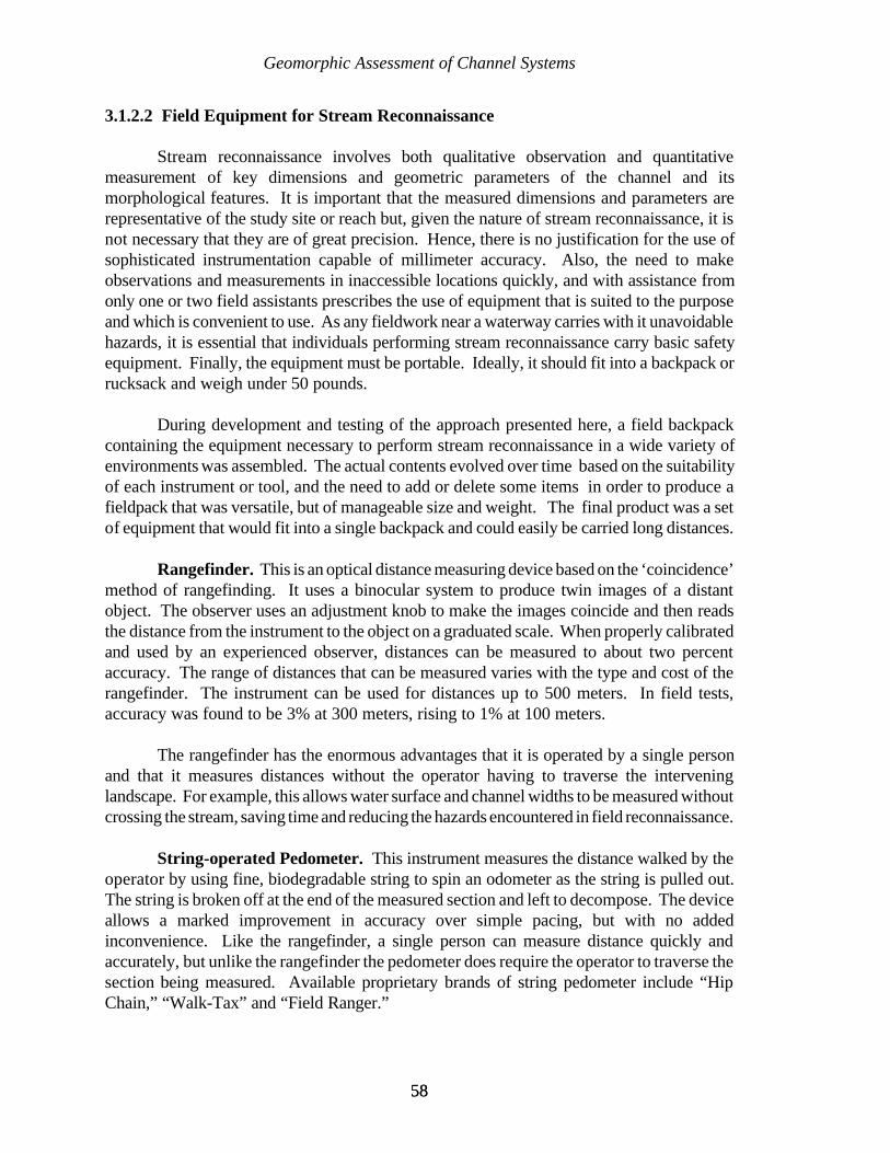
Geomorphic Assessment of Channel Systems
5858
3.1.2.2 Field Equipment for Stream Reconnaissance
Stream reconnaissance involves both qualitative observation and quantitativemeasurement of key dimensions and geometric parameters of the channel and itsmorphological features. It is important that the measured dimensions and parameters arerepresentative of the study site or reach but, given the nature of stream reconnaissance, it isnot necessary that they are of great precision. Hence, there is no justification for the use ofsophisticated instrumentation capable of millimeter accuracy. Also, the need to makeobservations and measurements in inaccessible locations quickly, and with assistance fromonly one or two field assistants prescribes the use of equipment that is suited to the purposeand which is convenient to use. As any fieldwork near a waterway carries with it unavoidablehazards, it is essential that individuals performing stream reconnaissance carry basic safetyequipment. Finally, the equipment must be portable. Ideally, it should fit into a backpack orrucksack and weigh under 50 pounds.
During development and testing of the approach presented here, a field backpackcontaining the equipment necessary to perform stream reconnaissance in a wide variety ofenvironments was assembled. The actual contents evolved over time based on the suitabilityof each instrument or tool, and the need to add or delete some items in order to produce afieldpack that was versatile, but of manageable size and weight. The final product was a setof equipment that would fit into a single backpack and could easily be carried long distances.
Rangefinder. This is an optical distance measuring device based on the ‘coincidence’method of rangefinding. It uses a binocular system to produce twin images of a distantobject. The observer uses an adjustment knob to make the images coincide and then readsthe distance from the instrument to the object on a graduated scale. When properly calibratedand used by an experienced observer, distances can be measured to about two percentaccuracy. The range of distances that can be measured varies with the type and cost of therangefinder. The instrument can be used for distances up to 500 meters. In field tests,accuracy was found to be 3% at 300 meters, rising to 1% at 100 meters.
The rangefinder has the enormous advantages that it is operated by a single personand that it measures distances without the operator having to traverse the interveninglandscape. For example, this allows water surface and channel widths to be measured withoutcrossing the stream, saving time and reducing the hazards encountered in field reconnaissance.
String-operated Pedometer. This instrument measures the distance walked by theoperator by using fine, biodegradable string to spin an odometer as the string is pulled out.The string is broken off at the end of the measured section and left to decompose. The deviceallows a marked improvement in accuracy over simple pacing, but with no addedinconvenience. Like the rangefinder, a single person can measure distance quickly andaccurately, but unlike the rangefinder the pedometer does require the operator to traverse thesection being measured. Available proprietary brands of string pedometer include “HipChain,” “Walk-Tax” and “Field Ranger.”
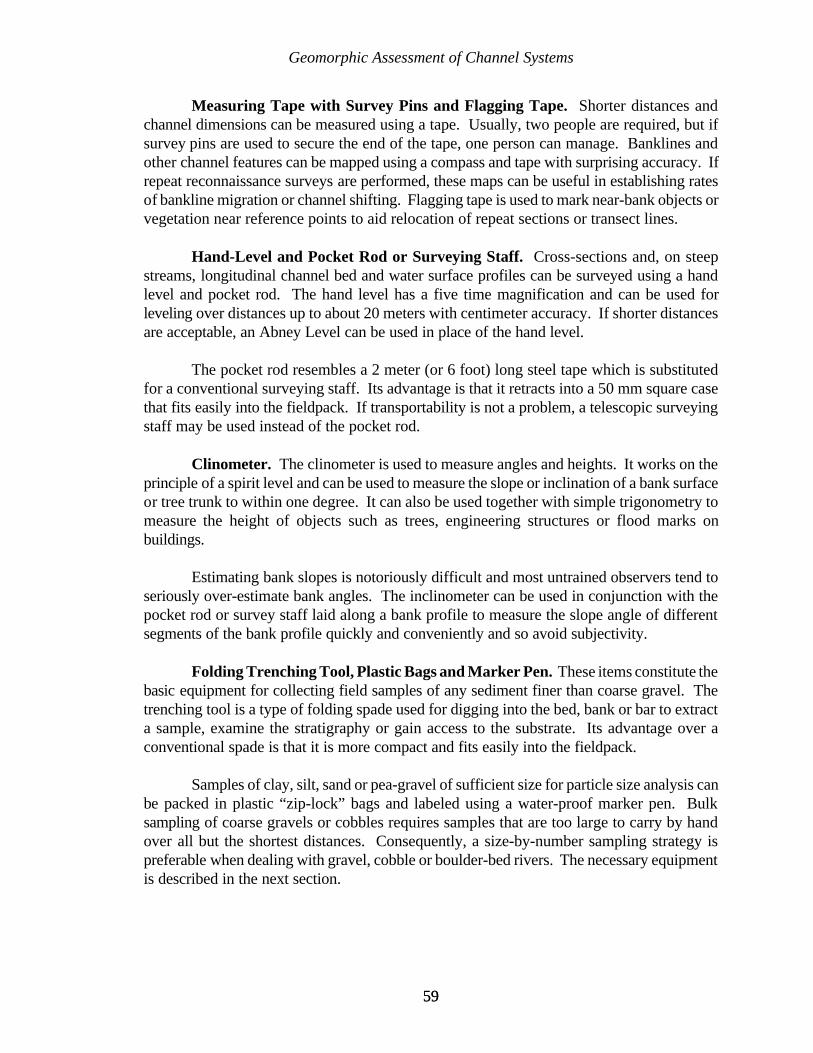
Geomorphic Assessment of Channel Systems
5959
Measuring Tape with Survey Pins and Flagging Tape. Shorter distances andchannel dimensions can be measured using a tape. Usually, two people are required, but ifsurvey pins are used to secure the end of the tape, one person can manage. Banklines andother channel features can be mapped using a compass and tape with surprising accuracy. Ifrepeat reconnaissance surveys are performed, these maps can be useful in establishing ratesof bankline migration or channel shifting. Flagging tape is used to mark near-bank objects orvegetation near reference points to aid relocation of repeat sections or transect lines.
Hand-Level and Pocket Rod or Surveying Staff. Cross-sections and, on steepstreams, longitudinal channel bed and water surface profiles can be surveyed using a handlevel and pocket rod. The hand level has a five time magnification and can be used forleveling over distances up to about 20 meters with centimeter accuracy. If shorter distancesare acceptable, an Abney Level can be used in place of the hand level.
The pocket rod resembles a 2 meter (or 6 foot) long steel tape which is substitutedfor a conventional surveying staff. Its advantage is that it retracts into a 50 mm square casethat fits easily into the fieldpack. If transportability is not a problem, a telescopic surveyingstaff may be used instead of the pocket rod.
Clinometer. The clinometer is used to measure angles and heights. It works on theprinciple of a spirit level and can be used to measure the slope or inclination of a bank surfaceor tree trunk to within one degree. It can also be used together with simple trigonometry tomeasure the height of objects such as trees, engineering structures or flood marks onbuildings.
Estimating bank slopes is notoriously difficult and most untrained observers tend toseriously over-estimate bank angles. The inclinometer can be used in conjunction with thepocket rod or survey staff laid along a bank profile to measure the slope angle of differentsegments of the bank profile quickly and conveniently and so avoid subjectivity.
Folding Trenching Tool, Plastic Bags and Marker Pen. These items constitute thebasic equipment for collecting field samples of any sediment finer than coarse gravel. Thetrenching tool is a type of folding spade used for digging into the bed, bank or bar to extracta sample, examine the stratigraphy or gain access to the substrate. Its advantage over aconventional spade is that it is more compact and fits easily into the fieldpack.
Samples of clay, silt, sand or pea-gravel of sufficient size for particle size analysis canbe packed in plastic “zip-lock” bags and labeled using a water-proof marker pen. Bulksampling of coarse gravels or cobbles requires samples that are too large to carry by handover all but the shortest distances. Consequently, a size-by-number sampling strategy ispreferable when dealing with gravel, cobble or boulder-bed rivers. The necessary equipmentis described in the next section.

Geomorphic Assessment of Channel Systems
6060
If it is desired to complete particle size analysis of sand-sized sediment in the field, afield sieve stack and electronic scale can be used, although the sieve stack will not fit into thefieldpack and must be carried separately.
Probe Rod. As well as sampling sediments, it is often useful to investigate thethickness of sedimentary units and of loose sediment stored in the bed and in bars, by usinga probe rod. A probe rod is also useful to examine the depth and extent of any tension cracksand piping cavities in the banks.
A variety of rods could be used for this purpose, but in the field tests carried out indeveloping the reconnaissance sheets presented here a jointed, stainless steel gun-cleaning rodwas found to be ideal. This rod is strong enough to penetrate most alluvial sediments,including densely packed sands, but can be taken apart to store neatly inside the fieldpack.
Gravelometer. The gravelometer is used to measure particle size in the Wolmanpebble-count or grid-by-number method of sampling armor layers and other alluvial gravelsthat are too course to be handled by bulk sampling. It is a light, thin sheet of aluminum alloywith square holes machined in it that follow the Wentworth Scale and range between 2 and180 millimeters in size.
Geological Hammer and Rock Identification Charts. The geological hammer isuseful for examination and sampling of rocks and other lithified materials encountered duringstream reconnaissance. A pack of rock identification charts, available from most supplier ofequipment for petroleum geology, can be very useful in assisting non-specialists in makingrudimentary observations concerning geological controls and influences on channel form andstability.
Miniature Cassette/Voice Recorder. A miniature cassette or voice recorder isextremely useful for taking notes to supplement the written and photographic records of areconnaissance trip. The recorder can be used to preserve thoughts or ideas triggered by fieldobservations and may be used during inclement weather and in other situations where writingor taking video would be impossible. Field notes may also be dictated immediately aftercompleting a survey or when traveling between sites, to be typed up later.
35mm Still Camera. A compact, automatic 35mm camera is suitable for fieldreconnaissance. A water proof or, at least weather proof camera should be used. Ideally oneequipped with a zoom lense should be chosen for versatility in photographing both wide,panoramic views of the river and floodplain, and detailed shots of bank and sedimentaryfeatures that are difficult to access closely.
Slide film is usually preferred over print film because slides are more compact to storeand are useful for illustrating and presentations concerning the project. Either prints or slidescan easily be scanned into a computer for electronic enhancement and storage, but ifcomputer-based storage is to be used, investment in one of the new, relatively inexpensive,
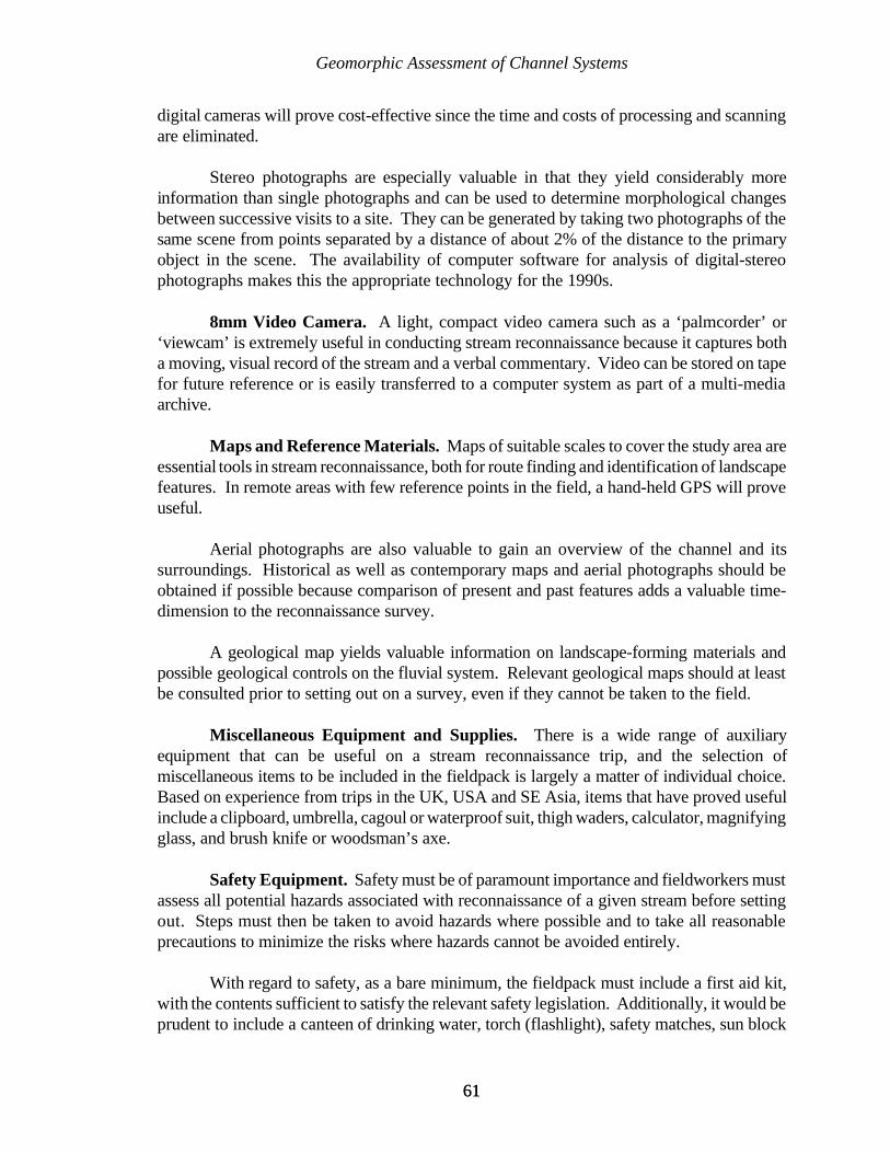
Geomorphic Assessment of Channel Systems
6161
digital cameras will prove cost-effective since the time and costs of processing and scanningare eliminated.
Stereo photographs are especially valuable in that they yield considerably moreinformation than single photographs and can be used to determine morphological changesbetween successive visits to a site. They can be generated by taking two photographs of thesame scene from points separated by a distance of about 2% of the distance to the primaryobject in the scene. The availability of computer software for analysis of digital-stereophotographs makes this the appropriate technology for the 1990s.
8mm Video Camera. A light, compact video camera such as a ‘palmcorder’ or‘viewcam’ is extremely useful in conducting stream reconnaissance because it captures botha moving, visual record of the stream and a verbal commentary. Video can be stored on tapefor future reference or is easily transferred to a computer system as part of a multi-mediaarchive.
Maps and Reference Materials. Maps of suitable scales to cover the study area areessential tools in stream reconnaissance, both for route finding and identification of landscapefeatures. In remote areas with few reference points in the field, a hand-held GPS will proveuseful.
Aerial photographs are also valuable to gain an overview of the channel and itssurroundings. Historical as well as contemporary maps and aerial photographs should beobtained if possible because comparison of present and past features adds a valuable time-dimension to the reconnaissance survey.
A geological map yields valuable information on landscape-forming materials andpossible geological controls on the fluvial system. Relevant geological maps should at leastbe consulted prior to setting out on a survey, even if they cannot be taken to the field.
Miscellaneous Equipment and Supplies. There is a wide range of auxiliaryequipment that can be useful on a stream reconnaissance trip, and the selection ofmiscellaneous items to be included in the fieldpack is largely a matter of individual choice.Based on experience from trips in the UK, USA and SE Asia, items that have proved usefulinclude a clipboard, umbrella, cagoul or waterproof suit, thigh waders, calculator, magnifyingglass, and brush knife or woodsman’s axe.
Safety Equipment. Safety must be of paramount importance and fieldworkers mustassess all potential hazards associated with reconnaissance of a given stream before settingout. Steps must then be taken to avoid hazards where possible and to take all reasonableprecautions to minimize the risks where hazards cannot be avoided entirely.
With regard to safety, as a bare minimum, the fieldpack must include a first aid kit,with the contents sufficient to satisfy the relevant safety legislation. Additionally, it would beprudent to include a canteen of drinking water, torch (flashlight), safety matches, sun block
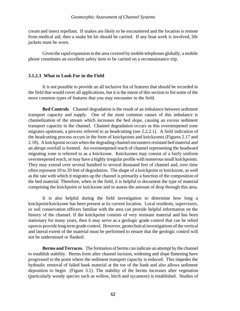
Geomorphic Assessment of Channel Systems
6262
cream and insect repellant. If snakes are likely to be encountered and the location is remotefrom medical aid, then a snake bit kit should be carried. If any boat work is involved, lifejackets must be worn.
Given the rapid expansion in the area covered by mobile telephones globally, a mobilephone constitutes an excellent safety item to be carried on a reconnaissance trip.
3.1.2.3 What to Look For in the Field
It is not possible to provide an all inclusive list of features that should be recorded inthe field that would cover all applications, but it is the intent of this section to list some of themore common types of features that you may encounter in the field.
Bed Controls. Channel degradation is the result of an imbalance between sedimenttransport capacity and supply. One of the most common causes of this imbalance ischannelization of the stream which increases the bed slope, causing an excess sedimenttransport capacity in the channel. Channel degradation occurs as this oversteepened zonemigrates upstream, a process referred to as headcutting (see 2.2.2.1). A field indication ofthe headcutting process occurs in the form of knickpoints and knickzones (Figures 2.17 and2.18). A knickpoint occurs when the degrading channel encounters resistant bed material andan abrupt overfall is formed. An oversteepened reach of channel representing the headwardmigrating zone is referred to as a knickzone. Knickzones may consist of a fairly uniformoversteepened reach, or may have a highly irregular profile with numerous small knickpoints.They may extend over several hundred to several thousand feet of channel and, over timeoften represent 10 to 20 feet of degradation. The shape of a knickpoint or knickzone, as wellas the rate with which it migrates up the channel is primarily a function of the composition ofthe bed material. Therefore, when in the field, it is helpful to document the type of materialcomprising the knickpoint or knickzone and to assess the amount of drop through this area.
It is also helpful during the field investigation to determine how long aknickpoint/knickzone has been present at its current location. Local residents, supervisors,or soil conservation officers familiar with the area can provide helpful information on thehistory of the channel. If the knickpoint consists of very resistant material and has beenstationary for many years, then it may serve as a geologic grade control that can be reliedupon to provide long term grade control. However, geotechnical investigations of the verticaland lateral extent of the material must be performed to ensure that the geologic control willnot be undermined or flanked.
Berms and Terraces. The formation of berms can indicate an attempt by the channelto establish stability. Berms form after channel incision, widening and slope flattening haveprogressed to the point where the sediment transport capacity is reduced. This impedes thehydraulic removal of failed bank material at the toe of the bank and also allows sedimentdeposition to begin (Figure 3.1). The stability of the berms increases after vegetation(particularly woody species such as willow, birch and sycamore) is established. Studies of
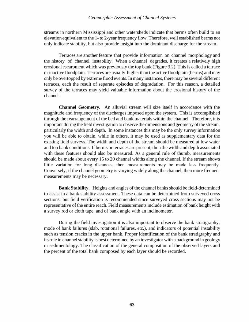
Geomorphic Assessment of Channel Systems
6363
streams in northern Mississippi and other watersheds indicate that berms often build to anelevation equivalent to the 1- to 2-year frequency flow. Therefore, well established berms notonly indicate stability, but also provide insight into the dominant discharge for the stream.
Terraces are another feature that provide information on channel morphology andthe history of channel instability. When a channel degrades, it creates a relatively higherosional escarpment which was previously the top bank (Figure 3.2). This is called a terraceor inactive floodplain. Terraces are usually higher than the active floodplain (berms) and mayonly be overtopped by extreme flood events. In many instances, there may be several differentterraces, each the result of separate episodes of degradation. For this reason, a detailedsurvey of the terraces may yield valuable information about the erosional history of thechannel.
Channel Geometry. An alluvial stream will size itself in accordance with themagnitude and frequency of the discharges imposed upon the system. This is accomplishedthrough the rearrangement of the bed and bank materials within the channel. Therefore, it isimportant during the field investigation to observe the dimensions and geometry of the stream,particularly the width and depth. In some instances this may be the only survey informationyou will be able to obtain, while in others, it may be used as supplementary data for theexisting field surveys. The width and depth of the stream should be measured at low waterand top bank conditions. If berms or terraces are present, then the width and depth associatedwith these features should also be measured. As a general rule of thumb, measurementsshould be made about every 15 to 20 channel widths along the channel. If the stream showslittle variation for long distances, then measurements may be made less frequently.Conversely, if the channel geometry is varying widely along the channel, then more frequentmeasurements may be necessary.
Bank Stability. Heights and angles of the channel banks should be field-determinedto assist in a bank stability assessment. These data can be determined from surveyed crosssections, but field verification is recommended since surveyed cross sections may not berepresentative of the entire reach. Field measurements include estimation of bank height witha survey rod or cloth tape, and of bank angle with an inclinometer.
During the field investigation it is also important to observe the bank stratigraphy,mode of bank failures (slab, rotational failures, etc.), and indicators of potential instabilitysuch as tension cracks in the upper bank. Proper identification of the bank stratigraphy andits role in channel stability is best determined by an investigator with a background in geologyor sedimentology. The classification of the general composition of the observed layers andthe percent of the total bank composed by each layer should be recorded.
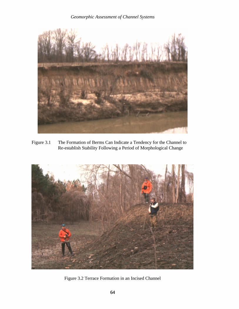
Geomorphic Assessment of Channel Systems
6464
Figure 3.2 Terrace Formation in an Incised Channel
Figure 3.1 The Formation of Berms Can Indicate a Tendency for the Channel toRe-establish Stability Following a Period of Morphological Change
Geomorphic Assessment of Channel Systems
6565
Vegetation. The spatial distribution, size, type, and approximate age of thevegetation existing within and along the channel should be recorded in the field investigation.Vegetation colonizing the channel and along berms should be evaluated with respect togrowth and whether or not it may be removed by the next flood event. Not only is substantialin-channel vegetation an indication of lateral stability, but it also impacts the hydraulicefficiency of the channel, and plays an important role in establishing the overall stability of thechannel. Simon and Hupp (1992) provide a detailed discussion of the use of vegetativeindicators of channel morphology.
Sediment Data. Major sediment sources supplying material to the main channelshould be recorded during the field reconnaissance. These sources may include the bed andbanks of the channel, tributaries, gullies, drainage ditches from roads and highways, andwatershed (upland) erosion. In many unstable streams, the bed and banks are a major sourceof sediment. In this case, the sediment is introduced into the system over a sometimes lengthyreach of channel. Tributaries that are undergoing similar instabilities may be sources of heavysediment input. During the field reconnaissance, the amount and size of sediment depositedat and just downstream of tributary confluences should be noted.
Sediment sampling provides information on the composition of the sediments derivedfrom each source. In general, channel bed material samples should be taken at the thalwegin order to obtain a representative sample. Analysis of these samples provides informationon the spatial variations of grain size within the channel system. Samples of channel bankmaterial, including if applicable, each stratigraphic layer, should be collected. Sediments intributary mouth bars are used to determine if tributary sediments are radically different fromthe main-stem channel sediments. It is also helpful to periodically collect bed materialsamples at several locations across a cross section in order to determine the lateral variabilityof sediment size in a section.
Hydrologic Factors. During the field investigation, estimates of channel roughnessshould be made for various reaches of the channel. These data are important for calibratingwater surface profiles in the detailed assessment phase of the investigation. Roughness(Manning’s ‘n’) should be estimated for the active channel, berms, and the floodplain.
Vegetation and trash frequently preserve evidence of water surface elevations duringfloods. Debris transported during floods is often trapped in the vegetation. The highwatermarks should be recorded, even if the method of measurement is crude. Any evidence offrequent overbank flows such as sand splays, overbank erosion, and crop damage, etc., shouldalso be noted during the field investigation.
Existing Structures. The location of all existing structures along the channel shouldbe recorded during the field reconnaissance. A partial list of common man-made featuresfound in streams includes bridges, bank protection, drop inlet structures, culverts, gradecontrol structures, water intakes, and pipelines. An assessment of the structure condition, andthe impact on the local channel morphology should be made during the field investigation.
Geomorphic Assessment of Channel Systems
6666
Evidence of scour at bridge pilings and culverts is particularly important as an indicator of theamount of degradation that has occurred since the construction of the structure.
3.1.3 CHANNEL STABILITY ASSESSMENT
The third phase of a geomorphic assessment involves an analysis of the channelstability. This is accomplished by the refinement and detailed analysis of all thehistorical and archive data previously collected, interpretation of the field reconnaissanceobservations, and the integration of these data to provide an overall assessment of the system.
3.1.3.1 Identification of Geomorphically Similar Reaches
One of the first steps in the channel stability assessment is to divide the channel intogeomorphically similar reaches. When establishing reach limits, consideration should be givento: changes in channel slope, tributary locations, presence of geologic controls, planformchanges, location of channel control structures (grade control structures, dams, culverts, etc.),changes in bed material size, major sediment sources (gravel mines, sediment laden tributaries,etc.), changes in channel evolution type, or other significant hydrologic or geomorphicchanges. Initial reach limits may be made early during the field investigation, but may berefined following more detailed analysis.
3.1.3.2 Specific Gage Analysis
Perhaps one of the most useful tools available to the river engineer orgeomorphologist for assessing the historical stability of a river system is the specific gagerecord. A specific gage record is a graph of stage for a specific discharge at a particulargaging location plotted against time (Blench, 1969). A channel is considered to be inequilibrium if the specific gage record shows no consistent increasing or decreasing trendsover time, while an increasing or decreasing trend is indicative of an aggradational ordegradational condition, respectively. An example of a specific gage record is shown in Figure3.3.

Geomorphic Assessment of Channel Systems
6767
YEAR
GAGE HEIGHT (MSL)
Figure 3.3 Specific Gage Plot for Red River at Index, Arkansas
The first step in a specific gage analysis is to establish the stage-discharge relationshipat the gage for the period of record being analyzed. A rating curve is developed for each yearin the period of record. A regression curve is then fitted to the data and plotted on the scatterplot. Once the rating curves have been developed, the discharges to be used in the specificgage record must be selected. This selection will depend largely on the objectives of thestudy. It is usually advisable to select discharges that encompass the entire range of observedflows. A plot is then developed showing the stage for the given flow plotted against time.
Specific gage records are an excellent tool for assessing the historical stability at aspecific location. However, specific gage records only indicate the conditions in the vicinityof the particular gaging station and do not necessarily reflect river response farther upstreamor downstream of the gage. Therefore, even though the specific gage record is one of themost valuable tools used by river engineers, it should be coupled with other assessmenttechniques in order to assess reach conditions, or to make predictions about the ultimateresponse on a river.
Geomorphic Assessment of Channel Systems
6868
3.1.3.3 Comparative Surveys and Mapping
One of the best methods for directly assessing channel changes is to compare channelsurveys (thalweg and cross section).
Thalweg surveys are taken along the channel at the lowest point in the cross section.Comparison of several thalweg surveys taken at different points in time allows the engineeror geomorphologist to chart the change in the bed elevation through time (Figure 3.4).
There are certain limitations that should be considered when comparing surveys ona river system. When comparing thalweg profiles it is often difficult, especially on largerstreams, to determine any distinct trends of aggradation or degradation if there are large scourholes, particularly in bendways. The existence of very deep local scours holes may completelyobscure temporal variations in the thalweg. This problem can sometimes be overcome byeliminating the pool sections, and focusing only on the crossing locations, thereby, allowingaggradational or degradational trends to be more easily observed.
While thalweg profiles are a useful tool it must be recognized that they only reflectthe behavior of the channel bed and do not provide information about the channel as a whole.For this reason it is usually advisable to study changes in the cross sectional geometry. Crosssectional geometry refers to width, depth, area, wetted perimeter, hydraulic radius, andchannel conveyance at a specific cross section.
If channel cross sections are surveyed at permanent monumented range locations, thenthe cross sectional geometry can be compared directly at different time periods. At eachrange, the cross section plots for the various time periods can be overlaid and compared.However, it is seldom the case that the cross sections are located in the exact same place yearafter year. Because of these problems it is often advisable to compare reach average valuesof the cross sectional geometry parameters. This requires the study area to be divided intodistinct reaches based on geomorphic characteristics. Next, the cross sectional parameters arecalculated at each cross section, and then averaged for the entire reach. Then the reachaverage values can be compared for each survey period. Cross sectional variability betweenbends (pools) and crossing (riffles) can obscure temporal trends, so it is often preferable touse only cross sections from crossing reaches when analyzing long-term trends of channelchange.
Comparison of time sequential maps can provide insight into the planform instabilityof the channel. Rates and magnitude of channel migration (bank caving), locations of naturaland man-made cutoffs, and spatial and temporal changes in channel width and planformgeometry can be determined from analysis of historical maps. With this type of data, channelresponse to imposed conditions can be documented and used to substantiate predictions offuture channel response to a proposed alteration. Planform data can be obtained from aerialphotos, maps, or from field investigations.
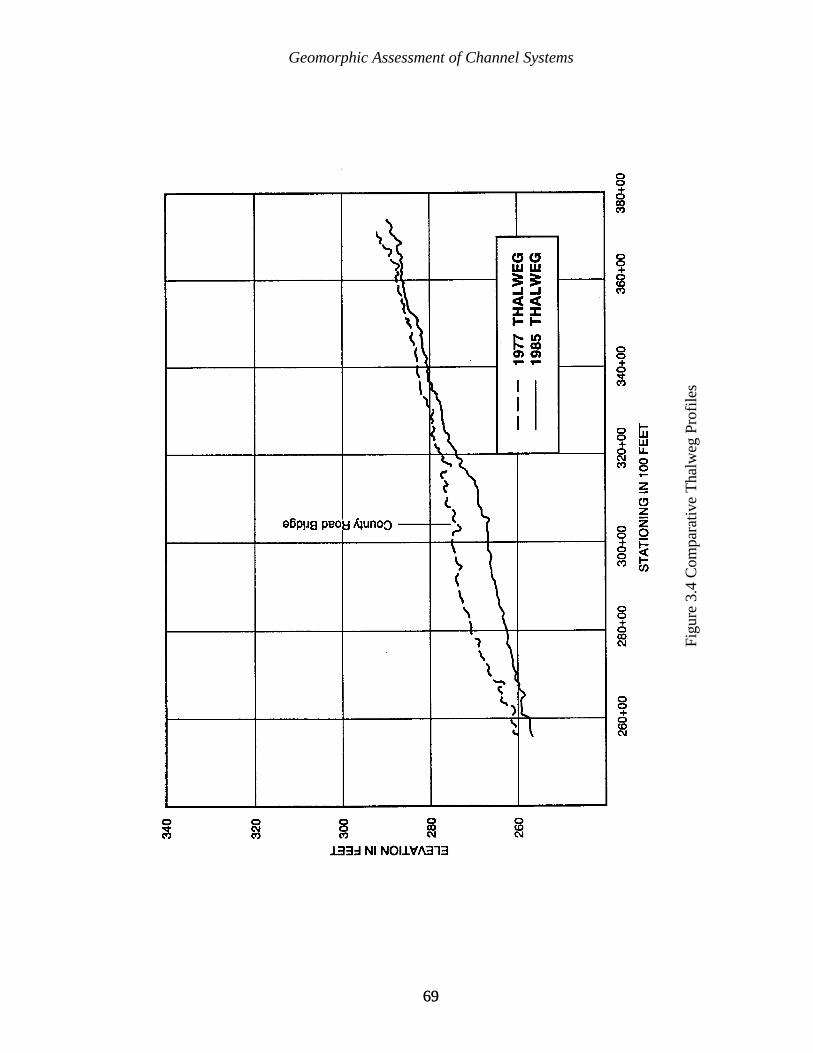
Geomorphic Assessment of Channel Systems
6969
Figu
re 3
.4 C
ompa
rativ
e T
halw
eg P
rofi
les

Geomorphic Assessment of Channel Systems
7070
ôo ' ãRSf (3.1)
V0 ' 0.84 m D 0.64 (3.2)
3.1.3.4 Empirical Methods for Stable Channel Design
Three types of stable channel design methods are reviewed in this section: maximumpermissible velocity, tractive force, and regime.
Maximum Permissible Velocities. In 1926, Fortier and Scobey presented a channeldesign method based on maximum permissible velocities for uniform flow. An earthenchannel was considered stable if the mean velocity of the channel is less than the maximumpermissible velocity for the channel. The USDA (1977) compiled data from Fortier andScobey (1926), Lane (1953), and the Union Soviet Socialist Republic (USSR, 1936) into aset of design charts. These charts are accompanied by a design procedure found in TechnicalRelease No. 25 (USDA, 1977).
Tractive Force Design. Lane (1953) developed an analytical design approach forshear distribution in trapezoidal channels. The tractive force, or shear force, is the forcewhich the water exerts on the wetted perimeter of a channel due to the motion of the water.It is the force exerted over an area of the bed or banks. It is equal to and in the oppositedirection from the force which the bed exerts on the flowing water. The average value of thetractive force per unit wetted perimeter (unit tractive force) is given by the following equation(Simons and Sentürk, 1992):
where ã is the specific weight of water, R is the hydraulic radius, and Sf is the energy gradeline. Simons (1957) provided a detailed process for Lane’s tractive stress method.
Regime Relationships for Channel Design. In 1895, Kennedy (Lacey, 1931)developed an early regime equation in India on the Upper Bari Doab Canal. The equation isas follows:
where: V0 = non-silting, non-scouring velocity, critical velocity;D = average vertical depth as measured on the horizontal bed of the channel
excluding side slopes; andm = silt factor.
Simons and Albertson (1963) continued regime development by combining data fromcanal studies in India (Punjab and Sind) and the United States (Imperial Valley, San LuisValley, and canals in Wyoming, Colorado, and Nebraska). Their motive for additionaldevelopment of regime analysis was the inadequacy of previous regime methods.
Geomorphic Assessment of Channel Systems
7171
Their data are separated into three groups based on the composition of streambed andstreambanks. This eliminates the need for computing bed, bank or silt factors needed forprevious equations. Simons and Albertson’s (1963) equations are referred to as the ModifiedRegime Equations.
The U.S. Army Corps of Engineers (USACE, 1994) provides guidance on channeldesign. Their recommendation is to use locally or regionally developed equations for channeldesign. However, when this is not possible, relationships are given to provide roughestimates for width, depth, and slope of a channel given the channel-forming discharge andbed material.
3.1.3.5 Summary of Empirical Channel Design Methods
This brief review of empirically-based channel design procedures shows that each ofthese methods is limited by at least one of the following two constraints:
C the empirical data set is representative of a limited amount of data for the widerange of stream and watershed types, and is not applicable outside the range ofdata for which each relationship was developed; or
C the concentration of sediment being transported is small, less than 500 ppm, andthe method requires that bed and bank materials are static.
While these methods are applicable within the limits for which each was developed, the twoprimary constraints listed dictate that empirical methods have limited application for naturalstreams.
3.1.4 Computational Design Methods for Channel Design
Two computer programs that can be used to aid in the design of stable channels areSAM (Thomas et al., 1993) and HEC-6 (USACE, 1993). SAM allows for channel designutilizing extremal hypotheses methods, and HEC-6 provides a method for computing bedstability of alternative channel designs.
3.1.4.1 SAM
Thomas et al. (1993) developed SAM, a computer program to calculate the width,depth, slope, and n-value for stable alluvial material. SAM is capable of determining stablechannel dimensions, calculating the bed material discharge, and calculating the sediment yieldof a stream. SAM is a relatively simple and quick computational procedure that allowspreliminary screening of design alternatives, and, in some cases, is suitable for final design orperformance monitoring.
Geomorphic Assessment of Channel Systems
7272
3.1.4.2 HEC-6
HEC-6 (USACE, 1993) is a one-dimensional moveable boundary open channel flownumerical model designed to simulate and predict changes in river profiles resulting fromscour and deposition over moderate time periods, typically years, although applications tosingle flood events are possible. A continuous discharge record is partitioned into a series ofsteady flows of variable discharge and duration. For each discharge, a water surface profileis calculated, providing energy slope, velocity, depth, and other variables at each crosssection. Potential sediment transport rates are then computed at each section. These rates,combined with the duration of the flow, permit a volumetric accounting of sediment withineach reach. The amount of scour or deposition at each section is then computed and thecross section geometry is adjusted for the changing sediment volume. Computations thenproceed to the next flow in the sequence and the cycle is repeated using the updated crosssection geometry. Sediment calculations are performed by grain size fractions, allowing thesimulation of hydraulic sorting and armoring.
HEC-6 is a powerful tool that allows the designer to estimate long term response ofthe channel to a predicted series of water and sediment supply. The primary limitation is thatHEC-6 is one-dimensional, i.e., geometry is adjusted only in the vertical direction. Changesin channel width or planform cannot be simulated.
3.1.4.3 Integration of Results
The final part of a geomorphic assessment of a channel system is accomplished byintegrating the information from all the available analyses. Analysis using each of thegeomorphic tools discussed previously may yield a verdict of aggradation, degradation, ordynamic equilibrium with respect to the channel bed, and stable or unstable with respect tothe banks. Often the individual assessments produce contradictory results. For instance, thefield investigations might indicate that a channel reach is vertically stable, but the empiricalrelationships and SAM results indicate that the channel should be degradational. In this caseyou would have to assign a level of confidence to the various components based on thereliability and availability of the data, and your own experience with each tool in order toreconcile these contradictory results. Once again we come back to the fact there is no“cookbook” answer, and that we must always incorporate sound judgement based on insightand experience when making a geomorphic assessment.
7373
CHAPTER 4
GENERAL APPROACH TO BANK STABILIZATION
This chapter forms the link between the analysis of channel stability and the selectionof appropriate solutions to problems of bank retreat.
“Complex problems often have quick and simple wrong answers” is an apt epigramfor problems of riverbank stabilization. River engineers and scientists may be pressured bycircumstances beyond their control to plan and construct riverbank stabilization works tooquickly, without adequate time or resources for a conceptual evaluation of the problem. Theimmediate need may be perceived as award of a construction contract when the immediateneed may, in reality, be a sound stability analysis of the channel system. The pressure toproceed prematurely to construction should be resisted with logic, while still recognizing thatthere are practical constraints on data collection and analysis, and that there is often a genuineneed for timely corrective action. River scientists and engineers have the privilege and dutyto educate the public, representatives of the public, project sponsors, and project managersabout river characteristics, and especially the response of rivers to human modification. Itmust be pointed out that mistakes in detailed design may be only mildly embarrassing andeasily correctable, but that mistaking the cause or degree of instability at the outset may doomthe entire project to eventual failure.
A more positive perspective is that a system analysis may also identify significantpotential benefits from bank stabilization works that might otherwise be neglected. Examplesof such benefits are improved water quality and reduction of downstream sedimentationproblems. Such benefits are difficult to quantify, and are likely to be achieved only bycomprehensive projects, but should be recognized.
Sometimes the obviousness of the bank failure mechanisms obscures the moreimportant underlying causes of bank failure. Without having had either the misfortune ofmaking serious mistakes, or the less traumatic experience of merely observing them, a personmay be prone to oversimplify the causes of bank retreat, because a river may take decades toreact to imposed changes. Also, the causes and effects of changes are inter-related throughcomplex response. Therefore, the more experienced the observer, usually the more cautioushe or she is about making initial judgements.
General Approach to Bank Stabilization
7474
The salient point is that before beginning the design of bank stabilization works, theconcepts and tools presented in the previous chapters on channel stability should be appliedsystematically and analytically to identify the processes and causes of instability. That analysismay lead to the conclusion that appropriate alternative solutions may involve more than site-specific bank stabilization. Finally, the planner should be aware of other factors which maybe peripheral to traditional engineering, but which are essential for a successful project,regardless of scope. This chapter presents a conceptual discussion of those alternatives andfactors.
4.1 CONSIDERATION OF AVAILABLE ALTERNATIVES
Problems of river instability in general can be addressed by one or more of thefollowing approaches:
River Basin ManagementLand treatmentReservoirs
Bed StabilizationSite-Specific Bank StabilizationRelocation of Stream or Endangered FacilityNon-structural Solutions
Regulation of navigationRegulation of reservoir releases
The detailed planning and design of the first two alternatives is complex, and beyondthe scope of this text. However, the discussion in this section will serve to set them inperspective for the detailed presentation in Chapters 5 through 11 of the selection, design,construction, and maintenance of site-specific bank stabilization, and the presentation inChapter 12 of concepts of bed stabilization. The last two alternatives are limited inapplicability and effectiveness, but consideration of them may be appropriate in somecircumstances.
Technical capability to analyze these alternatives is rapidly improving, not onlythrough increased knowledge of river processes, but also through rapid advances in thecomputational capacity of computers which makes numerical models more powerful.Unfortunately, constraints on time and funds often precludes full application of the moreadvanced technical tools which are available.
If a problem is purely local, and authority to address a wider project scope does notexist, then the following discussion is academic to a reader searching only for guidance fora conventional approach to bank stabilization. However, if project authority is broader, thenthe optimum solution may include other components. For example, flood control projects andriver restoration schemes may require the evaluation of channel system response to changes

General Approach to Bank Stabilization
7575
in flow or channel characteristics. Bank stability can then be addressed as an integral part ofthat evaluation.
4.1.1 RIVER BASIN MANAGEMENT
This approach is feasible only in comprehensive projects. A large part of the basinmust be controlled or managed to be effective in stabilizing the downvalley streams.Significant local cooperation, social and economic constraints, and legal safeguards areinvolved, and if measures that are comprehensive enough to significantly reduce channelinstability are implemented, the project may have complex effects on other aspects of long-term stream behavior.
The operational aspects and effectiveness of basin management depends on basincharacteristics such as topography, land use, climate, soil types, vegetation, and rainfallpatterns. The two major components of basin management are land treatment and reservoirs.
4.1.1.1 Land Treatment
Major components of land treatment are:
Riparian greenbelts Agricultural practices to minimize runoff and erosion
No-till plantingCrop rotationContour plowing and terracingImproved management of irrigation flows
Improved forestry practicesLimits on clear-cuttingCareful collecting and hauling practices
Improved grazing practicesStable runoff channels
Benefits of land treatment to channel stabilization are as follows:
Peak discharges are reduced somewhat, thus reducing streamflowattack on the banks, as well as perhaps providing some flood controlbenefits.
Sediment supply to the stream system is also reduced, which resultsin a reduction in channel aggradation and associated flood problems,as discussed by Liu (1989) for the Yellow River, and an improvementin water quality and navigation depths downstream. The preciseeffects depend on the character of the sediment supply and other basin

General Approach to Bank Stabilization
7676
and channel characteristics. The drawback of this approach is that asignificant change in the sizes of the sediment mixture may inducesome channel instability by changing the river regime and triggeringsome response in channel shape, planform, and/or slope. These areeffects which cannot be precisely predicted.
Land loss from overland erosion and gullying is reduced.
4.1.1.2 Reservoirs
The primary purpose of reservoir construction is usually flood control or watersupply, but reservoirs also may be designed specifically to induce channel stability. Reservoirsmay also be designed specifically to trap sediment. These are sometimes called “debrisbasins,” and require periodic removal of sediment until the basin is stabilized (U.S. ArmyCorps of Engineers, 1991).
The effect of reservoirs is to reduce peak discharges and sediment supply to thedownstream channel. In this regard, their impacts can be viewed qualitatively as the same asland treatment, but the effect is of much greater magnitude. The potential benefit to channelstability is, therefore, much greater, but so is the risk of induced instability due to a changein river regime.
A reduction in peak discharge often reduces bank instability by inducing depositionat the channel margin in the form of berms. In effect, the channel adapts to a lower effective,or dominant, discharge by shrinking. However, reducing the sediment supply to the streamalso often induces channel degradation downstream, which can actually lead to massinstability by increasing bank heights. Reducing peak discharge and lowering the flowlinesin the downstream channel may also induce tributary instability by lowering their effectivebase level. This may trigger a reversal of main channel response and lead to its eventualaggradation due to increased sediment supply from tributaries (Biedenharn, 1983).
The effect of reservoirs on rapid changes in river stage can also be significant. Thenature of the effect on bank stability depends on the shape of the stage hydrograph of thestream before reservoir construction and the manner in which discharges from the reservoirare regulated, as discussed in 4.1.5.2.
If there is consumptive use or interbasin transfer from reservoirs, for irrigation orwater supply, the potential for channel response is further complicated by the reduction oftotal volume of flow as well as peak discharge.
Bank failure upstream of reservoir impoundments will be decreased by the reductionin flow velocities and bank shear stresses for the length of channel affected by theimpoundment. However, associated raising of flowlines due to channel aggradation maycreate flood control and environmental quality problems.
General Approach to Bank Stabilization
7777
The preceding account illustrates the fact that, even though reservoir construction maychange a stream's water and sediment supply in a relatively straight-forward manner, reliablepredictions of the ultimate effects on bank stability and stabilization procedures are elusive.
4.1.2 BED STABILIZATION
Assessing the need for bed stabilization measures requires not only a quantificationof the active processes of degradation, but also knowledge of the erodibility of bed andsubstrate materials throughout the entire system, because the rate and magnitude ofdegradation is very sensitive to bed erodibility. This presents a difficult task if the geologicand morphologic history of the basin is complex. Even with ample data, the erodibility ofcohesive soils and weak rocks cannot be accurately predicted. Numerical models do notaccount for cohesive materials well, and often the best approach is an empirical one, basedon the known historical behavior of the particular system in question. If a proposed projectwill significantly change either the inputs of water or sediment, or the channel slope, then evenchannel history is not a reliable guide, and design safety factors should be large.
If significant bed degradation is occurring or is expected, then a project should includebed stabilization measures. The only exception is if the requirement or authority for bankstabilization is limited to a very few sites. Local stabilization can be achieved without bedstabilization by designing the toe of the bank protection to function despite general beddegradation. However, this protects only the immediate area of the project. Also, whenapplied to several sites, the cost of heavy toe protection can exceed the cost of bedstabilization measures without yielding the broader benefits of bed stabilization. A detaileddiscussion of bed stabilization techniques and design guidance is given in Chapter 12.
4.1.3 SITE-SPECIFIC BANK STABILIZATION
This approach is a simpler concept to implement, carries a relatively low risk ofinduced channel system instability, and is the most immediate and tangible solution.However, unless properly planned and designed, the risk of failure is high. It will be the onlycomponent required if project scope is limited to a particular site or local reach of stream, orif the initial conceptual analysis has determined that the stream is in dynamic equilibrium andthe predominant cause of bank failure is of local origin. Chapters 5 through 9 discuss theplanning and design of site-specific bank stabilization works in detail.
General Approach to Bank Stabilization
7878
4.1.4 RELOCATION OF ENDANGERED FACILITY OR STREAM CHANNEL
These alternatives may require the smallest initial expenditure to “solve,” or at leastpostpone, bank stability problems. They usually have little else to recommend them.
4.1.4.1 Relocation of Endangered Facility
This approach may be dictated by public policy or private preference if it is the leastcostly alternative. It obviously has no impact on stream characteristics, which can be apositive or a negative factor, depending upon the particular circumstances. It would be mostlikely to be a positive factor in environmentally sensitive areas where construction of worksin the stream channel is to be avoided if possible. The relocation of a structure to a place ofsafety requires an accurate prediction of the rate and direction of channel migration.
Factors which affect the feasibility of structure relocation are:
Cost;Degree of safety required to be provided by relocation; andSocial and political impacts of relocation.
4.1.4.2 Relocation of Stream Channel
Factors which affect the feasibility of stream channel relocation are:
Cost ;Potential for induced damages;Stream regime; andPotential environmental benefits of the abandoned channel.
Channel relocation does not always induce instability upstream or downstream, butadjacent landowners are likely to believe otherwise, and legal actions may result. Streamregime and local site conditions determine whether relocation of the channel will cause seriousproblems. Stabilization of the relocated channel itself may be necessary to avoid problemscaused by it migrating after it is constructed. Environmental benefits may result from theformation of a new and abandoned channel, but such benefits are often difficult to maintainpermanently unless the sediment load of the stream is relatively small.
General Approach to Bank Stabilization
7979
4.1.5 NON-STRUCTURAL SOLUTIONS
Two situations where a non-structural alternative may be considered are:
Erosion due to navigation traffic in confined channelsBank instability caused by varying reservoir releases
4.1.5.1 Regulation of Navigation
Regulation of vessel size and speed to reduce erosion from boat or ship passage is apreferable solution and has major environmental benefits, but it may be legally or politicallyimpractical, depending on the local situation. Prediction of the reduction in erosion fromregulation is also difficult, which compounds the legal and political problem. Also, publicperception of the cause of erosion tends to overemphasize the actual effects of vessel traffic.
4.1.5.2 Regulation of Reservoir Releases
This approach presents much similar benefits and problems as regulation ofnavigation. Reservoir releases are usually dictated by multiple purposes, and their impact onbank stability is likely to be well down the list of priorities. Also, the public perception ofdamages from reservoir operation may far exceed the actual damages. In fact, as discussedin Section 4.1.1.2, the net effect of reservoirs is often to improve bank stability. Twoexceptions may exist:
If discharge from a reservoir is frequently and rapidly reduced from close tobankfull to no flow or low flow, geotechnical instability may be increasedcompared to natural conditions.
If reservoir operation increases the duration of high in-bank flows, the totalamount of bank erosion associated with those flows will obviously increase.However, an increase in long-term erosion will be difficult to prove, becausethe accompanying reduction in peak flows and their associated erosion maymore than compensate.
4.2 CONSIDERATION OF OTHER FACTORS
A project which performs adequately by traditional engineering standards cannevertheless create public dissatisfaction, because the public takes good engineering forgranted, and sometimes focuses on the project's negative aspects. This negative focus mayresult from inadequate consideration by the project planners of factors which may be beyondwhat is traditionally considered to be included in the engineering of a project.
General Approach to Bank Stabilization
8080
The degree of importance and the particulars of these factors are site-and-timespecific. It is impossible to address them completely in this text, but they are discussedsufficiently to allow their consideration in the context of proposed bank stabilization, and toraise awareness that further investigation may be appropriate for a specific project.
The factors to be considered are:
Legal and regulatory matters;Broad environmental issues;Economic factors; andCoordination with other interested parties.
4.2.1 LEGAL AND REGULATORY MATTERS
Public concerns which are most likely to require permits or conformity to law orformal regulatory procedures are:
Navigation;Environmental restrictions;Cultural resources;Rights of way; andOther consequential project-induced effects.
Proposed work where commercial navigation exists has obvious constraints. Lessobvious is the possibility that work may be proposed where there appears to be no actualnavigation, but an official classification of the river as a “navigable” waterway exists,requiring the same regulatory procedures.
Public or interagency review of environmental aspects of the project may be required.Environmental requirements are rapidly becoming more stringent and complex, and allproposed projects, no matter how small or innocuous, should be critically examined early inthe planning stages. Section 4.2.2 presents a broader view of this matter.
Cultural resources affected by river stabilization projects are usually archaeologicalor historical sites. The impact may be positive, as when sites are protected from potentialdestruction by bank failure, or negative, as when sites are subject to damage fromconstruction activities associated with stabilization projects. Potential impacts are oftenaddressed together with environmental considerations, but specific procedures vary.Consultation with the project sponsor or other project planning authorities is necessary todefine the required coordination.
Right-of-way for construction, surveillance, and maintenance is always required insome form. It may vary from a simple temporary easement to a complex fee-title purchasefrom many parties, all of whom may not welcome the project.
General Approach to Bank Stabilization
8181
Other consequential effects of a proposed project may be less well-defined, butperhaps more troublesome. Potential sources of liability and potential litigation are:
Induced bank instability elsewhere;Induced flooding; andPhysical injury and property damage due to the project.
The engineering aspects of these factors will have been partially addressed in theanalysis of stream stability, and will be further addressed during the selection and design ofstabilization work. However, the legal aspects are another matter, and early examination bythe pessimistic eyes of lawyers reduces the probability of subsequent legal problems arising.
4.2.2 BROAD ENVIRONMENTAL ISSUES
The previous section stated that environmental factors must usually be addressed byformal legal or regulatory procedures. This section discusses the following broader concepts:
Historical evolution of public perception;Opportunities and hazards; andPublic and inter-agency cooperation.
4.2.2.1 Historical Evolution of Public Perception
Future generations will likely judge us primarily on how well we protect theenvironment. Just as society now regrets indiscriminate dumping of toxic wastes anddrainage of wetlands - once condoned for the sake of presumed economic progress - itincreasingly regrets many of the environmental sacrifices which have been made in waterresource projects for the sake of economic benefits. Brookes (1988) provides acomprehensive discussion of riverine environmental concerns, and a history of the translationof public awareness into law, policy, regulation, and practice.
A policy statement by the Commander of the U. S. Army Corps of Engineers, GeneralH.J. Hatch, on 14 February 1990 illustrates the changing public perspective on environmentalissues:
“....the environmental aspects of all we do must have equal standingamong....economics and engineering” and “Our commitment must be toenvironmentally sustainable development in which we do not compromise thefuture while we meet current needs.”
Nationwide competition within the Corps of Engineers for environmental designawards encourages the application of this policy to practice.
General Approach to Bank Stabilization
8282
Beyond the altruism of economic sensitivity, most river engineering and managementagencies are now more attentive to non-traditional methods for quantifying the economicbenefits of environmentally preferable alternatives.
4.2.2.2 Opportunities and Hazards
Greater opportunities for creativity and innovation exist in the environmental aspectsof riverbank stabilization than in the more obvious and traditional aspects of river science andengineering. A creative attitude can be catalyzed by recognizing environmental considerationsas worthwhile challenges and opportunities, rather than as burdensome requirements,although this attitude may be difficult to maintain in the face of pressing schedules andfunding constraints. The task is made easier, and goals are achieved more effectively, byaddressing environmental concerns as early in the planning process as possible.
Although riverbank stabilization does not have the dramatic environmental impact ofreservoir construction or channelization of rivers, significant environmental hazards andopportunities do exist. An important distinction, between channelization and stabilization,must be made here, so that perception of the former does not unjustly condemn the latter.The distinction is often overlooked by the public, and is sometimes blurred in the literature.Channelization implies significant alteration of long reaches of a stream, often to the detrimentof channel stability and environmental quality, whereas bank stabilization often providesenvironmental benefits, as discussed in 5.2.
All riverbank stabilization projects impact the environment, regardless of the meansused to stabilize the channel (Henderson and Shields, 1984). Some potential impacts are:
Flood plain development or increased agricultural activity may be inducedwhen the threat of channel migration is reduced or removed.
Eroding bank habitat, which is more valuable ecologically than one mightthink, will be reduced, and the growth of bars and successional vegetation willbe altered, perhaps at the expense of habitat diversity. Bed materialcomposition, flow distribution, and other in-channel habitat factors may alsobe affected.
The formation of ecologically valuable abandoned channels (“oxbows”) willbe prevented, a serious consequence since existing oxbows usually deterioratewith age due to sedimentation.
Some types of maintenance activities may discourage the reestablishment ofnatural conditions after the project is complete.
The river scientist's task is to recognize the potential impacts, and then to minimizethe bad and maximize the good.
General Approach to Bank Stabilization
8383
4.2.3 ECONOMIC CONSTRAINTS
It was pointed out in Section 4.1 that problems generated by bank instability maysometimes be most effectively and economically solved by less obvious alternatives thansite-specific bank stabilization works, especially if the problems are a result of systeminstability. Section 5.3 further discusses economic factors involved in the selection of site-specific bank protection methods. However, it may be appropriate at an early stage in projectplanning to consider economic constraints beyond the fundamental engineering concept ofobtaining the best value for funds expended. Two such factors are:
Does the viability of the project depend upon a formally calculated favorablebenefit to cost ratio, or will the project be constructed to satisfy specific needsregardless of economic calculations, such as to protect a historic site ofindeterminate value? The latter provides the most engineering flexibility, butthe former is the most likely situation, in which case the procedure forestimating costs and benefits is probably specified either by the engineer'sorganization or the project sponsor.
Does the project sponsor have the means and commitment to pay for awell-engineered project, including data collection and an analysis of the causesof the problems and alternative solutions? If not, it is the engineer's duty topoint out the hazards of not doing so, in the hope that a more thoroughanalysis will be authorized.
These considerations are often complicated by the fact that the cost of bankstabilization may exceed the economic value of land and facilities to be directly protected.However, the economic analysis for projects based on broad studies can include identificationof less immediately obvious benefits, such as the reduction of sedimentation problemsdownstream, which may have the potential for benefitting flood control, navigation, andenvironmental quality.
4.2.4 COORDINATION WITH OTHER INTERESTED PARTIES
Most project requirements will be satisfied by adhering to the suggestions in thepreceding sections and those in subsequent chapters on design, construction, andmaintenance. However, there are usually other interested parties who should be notified orconsulted, at least informally. Viewing the specific situation from an “outsider's” perspective,or asking someone less involved in the details of the planning to do so, will usually identifythose parties, thus identifying potential non-engineering problems early on. Public noticesthat may be required by law can also be used as opportunities in this regard, rather thangrudgingly satisfying only the letter of the requirement for the notice.

General Approach to Bank Stabilization
8484
8585
CHAPTER 5
SELECTION OF SITE-SPECIFIC STABILIZATION TECHNIQUES
This chapter presents a rational approach to the solution of site-specific bankstabilization problems. It is assumed that application of the insights and analyses presentedin the first three chapters has led to the identification of the causes and mechanisms of bankinstability. It is also assumed that the conceptual analysis described in Chapter 4 hasdetermined that site-specific bank stabilization is to be a project component, perhaps the onlycomponent. Selection of a stabilization approach logically follows that determination, andlogically precedes preparation of the detailed project design discussed in Chapters 5 through9.
The reader might logically question why detailed descriptions of alternativetechniques, and their advantages, disadvantages, and typical applications, are not discussedin this chapter rather than later in the text. The author's dilemma was that those topics areeven more integral to the design concepts discussed later in the text than to selection oftechniques. The discussion, therefore, follows what seems to be the most efficient andcomprehensible format overall. Because it is impossible to neatly segregate all topics, someredundancy is unavoidable, but an attempt was made to minimize it. Hopefully the dilemmaproves to be less painful in practice than it is in concept, because all pertinent material shouldbe examined by the reader, regardless of its location in the text. Also, some readers willalready be familiar with many techniques, and even those readers who are not experienced inbank stabilization will find that one can intuitively grasp many concepts of selection withouta tedious search through the text for supporting material.
A framework for selection can be expressed by “Three E's”:
Effectiveness of alternative approaches;Environmental considerations; andEconomic factors.
The rationale for using this framework is that inherent factors in the properties of agiven bank stabilization technique, and in the physical characteristics of a proposed worksite,influence the suitability of that technique for that site. It is essential here to distinguishsuitability, which is governed by those inherent factors, from adequacy, which is governedby design decisions. In other words, the selection phase focuses on suitability, while the
Selection of Site-specific Stabilization Techniques
8686
design phase focuses on adequacy. Both of these then determine the effectiveness of thetechnique. Many techniques can be designed to adequately solve a specific bank stabilityproblem by resisting erosive forces and geotechnical failure. The challenge to an engineer isto determine the most suitable, the most effective solutions to a specific problem, to recognizewhich technique matches strength of protection against strength of attack, and whichtherefore performs most efficiently when tested by the strongest process of erosion and mostcritical mechanism of failure. Environmental and economic factors are integrated into theselection procedure, but the chosen solution must first fulfill the requirement of beingeffective as bank stabilization, otherwise environmental and economic attributes will beirrelevant.
Application of the concepts discussed in this chapter can be enhanced by consideringthe following philosophical suggestions:
Be innovative. Old concepts can be adapted to specific situations in creativeways, but only if a problem is approached with a creative attitude.Brainstorming with others is helpful in this regard. However, whilemaintaining a creative attitude, do not reinvent the wheel. Learn from others'experience, then reexamine previous practice creatively.
5.1 EFFECTIVENESS OF ALTERNATIVE APPROACHES
The following factors of effectiveness influence the selection of a bank stabilizationmethod for a specific project:
Durability;Adjustment to scour or subsidence;River depths;Foreshore limitations;Channel alignment;Impact on flowlines; andImpact on erosion upstream and downstream.
5.1.1 DURABILITY
The following factors should be considered in evaluating the durability of alternativemethods:
Required project lifespan;Maintenance requirements and capability;Climatic conditions;Debris loads, including ice;Corrosion and abrasion; andOther hazards.
Selection of Site-specific Stabilization Techniques
8787
5.1.1.1 Required Project Lifespan
This factor will determine the degree of importance of the durability of alternativemethods to a particular project. Required project lifespan is seldom truly quantifiable, eventhough those projects which require a formal economic analysis must be assigned a specificproject lifespan. In practice, the selection of techniques usually involves only a qualitativeassessment of required project lifespan, a choice between a “short-term” or a “long-term”lifespan.
Two examples of situations involving only a short-term required project lifespan are:
Emergency stabilization during an unusual flow event, which requiresimmediate action under conditions not permitting the design and constructionof a permanent solution, conditions which may be so rare as to not justify apermanent project.
Local stabilization on a rapidly migrating stream where the attack at the areaof concern will be of short duration, and the probability of severe attackoccurring at the same point in the foreseeable future is low, or at leastacceptable.
The extreme case of required project lifespan being long-term is the most commonsituation. When in doubt, a long-term project lifespan should be assumed, since labor andequipment costs are usually the most expensive part of the project, and a small premium fordurable materials will usually provide a cost-effective increase in the factor of safety.
A classification of intermediate project lifespan may be appropriate in special cases:
When an eroding channel is to be stabilized with the expectation that a futureproject will result in the relocation of either the stream channel or theendangered structure.
When a project for stabilizing a local erosion problem will eventually beendangered from downstream by channel degradation or from upstream by amigrating bend. This factor is, therefore, related to the determination ofproject components, and to the determination of upstream and downstreamlimits of the project, discussed in 6.1.1.
Selection of Site-specific Stabilization Techniques
8888
5.1.1.2 Maintenance Requirements and Capability
Evaluating this factor involves weighing a lower initial cost or constructionexpediency against the potential for deterioration of the project as a result of inadequateinspection and maintenance.
If the project sponsor has the capability to monitor the condition of the project, andmaintain it as required, a less durable technique may be preferable to a more durable methodrequiring a higher initial investment. This is particularly likely if inexpensive labor, equipment,and local materials are available. However, the engineer should be cautious about relying tooheavily on future maintenance capability, for two reasons:
The capability of the sponsors to maintain the project may change due tofactors beyond their control; and
Human nature may make it easier for the sponsor to agree to an obligation tobe incurred in the future than to fulfill that obligation when it comes due.
This is a project-specific determination, but a decision to select a less durabletechnique should not be made without a frank, even pessimistic, evaluation of the sponsor'slong-term commitment and capability, and the durability of the protection methods beingconsidered.
The consequences of failure of the project are linked both to maintenancerequirements and to the determination of required durability. However, it is more critical tothe detailed design of the project than to the selection of a particular method, since mostmethods can be designed with a low risk of failure. This is discussed further in 6.6, “SafetyFactor.”
5.1.1.3 Climatic Conditions
Climatic conditions affect durability through the action of:
Freezing and thawing cycles;Ice floes;Heaving;Wetting and drying cycles; andSunlight (ultraviolet deterioration).
The primary vulnerabilities here are the effect of freezing and thawing on stone, theeffect of ice floes on armor and indirect protection structures, the effect of heaving on slopearmoring, the effect of wetting and drying (with the accompanying damage by bacterialgrowth and insects, on wooden components), and the effect of sunlight on synthetic materials.
Selection of Site-specific Stabilization Techniques
8989
Although stone which is not submerged below the winter freeze line can be damagedby freezing and thawing, that is not necessarily a deterrent to the selection of stone as theerosion protection material in cold climates. The primary measure to combat stonedeterioration is to insure that high quality stone is used, as demonstrated by local experienceor tests. In severe applications, consideration can be given to increasing stone size beyondthat which is adequate for hydraulic stability in order to partially compensate for laterfracturing.
Ice floes uplifting and removing stone and other armor or dike and retard materialsmay be a problem to be considered in the light of local experience.
Rigid armors are more susceptible to damage from heaving than are adjustablearmors, flexible mattresses, and indirect techniques.
Permanent submergence greatly reduces deterioration of wooden components fromwetting and drying, and damage to synthetic materials from sunlight. These materials areoften used above low water line, but special treatment is usually required. Manufacturers ofsynthetic materials can provide information for their products.
5.1.1.4 Debris Loads
Debris, in the form of uprooted trees or ice carried by the flow, can cause suchextensive damage on some streams as to rule out some techniques entirely, and may make thecost of others prohibitive if they are designed to withstand debris loads. However, debris canalso affect bank stabilization work positively. Examples of this are:
Debris can increase the effectiveness of structures in reducing near- bankvelocities and accumulating sediment, but debris can also fail structures whichaccumulate large debris in zones of high velocity, and can make the structuresmore vulnerable to fire.
Comprehensive stream stabilization will eventually reduce debris loads, butstructures must usually be designed for the heavier interim loads.
Debris accumulated by stabilization works may provide habitat for wildlife,but in populated areas the debris may be considered unsightly, and the wildlifeit attracts may be pests to nearby residents.
Whether the net result of these interactive events is positive or negative must bedetermined by applying engineering and environmental judgement to the particular siteconditions and project purposes. The sum is often negative, and so the selection of atechnique which is likely to accumulate debris, such as permeable dikes or retards, must beapproached cautiously if a stream carries large debris loads.
Selection of Site-specific Stabilization Techniques
9090
5.1.1.5 Corrosion and Abrasion
These mechanisms can greatly reduce the durability of structures which rely onmetallic components for long-term structural integrity. The critical factors are waterchemistry, air quality, and the concentration and velocity of coarse sediment impinging on themetallic components. A corrosive or abrasive environment does not necessarily rule out theuse of vulnerable techniques, but it does dictate that they be approached cautiously and thatthey be carefully designed.
If metallic components are used the most vulnerable structures are the following:
Flexible mattresses of:Concrete blocksGabionsUsed tiresWood;
Dikes; andRetards.
Three ways of avoiding failure in a corrosive/abrasive environment are:
• Select a technique that has a high resistance to corrosion and abrasion, such as:
Stone or other self-adjusting armor;Rigid armor;Gabions grouted with asphalt or mastic;Flexible mattress without metallic components; andStone dikes;
• Use special components which are highly resistant to the worst-case agent at thesite, such as heavily galvanized or pvc-coated metal and wire, and stainless steel orsynthetic fasteners and strand. Even this may not assure success if highly corrosiveor abrasive conditions exist, particularly if high concentrations of coarse sediment,high velocities, and highly corrosive water are all present. Even galvanized orcoated components are susceptible to “nicking” of the protective layer duringconstruction, which may affect their integrity.
• Use a “zone” selection concept, the zones being:
Below low water;Between low water and the permanent vegetation line; andAbove the permanent vegetation line.
Materials in the zone below low water must resist only water-borne corrosiveagents and abrasive sediments. Materials between low water and permanent
Selection of Site-specific Stabilization Techniques
9191
vegetation must withstand both water-borne and air-borne agents, and to a lesserdegree, abrasion by sediment. Materials above the permanent vegetation line maynot need to be highly resistant if site conditions insure that vegetation will becomeestablished sufficiently well to function as upper bank protection after the metalliccomponents deteriorate. However, practical considerations of design andconstruction may make simply using a single design that will withstand the worstcase less costly than using the “zone concept.”
5.1.1.6 Other Hazards
The following destructive agents are potential problems in some cases:
Vandalism;Theft;Animals;Insects; andFire.
Selecting a technique which minimizes temptation will reduce problems withvandalism and theft. Some materials which are obvious targets for vandals and thieves areposts, boards, concrete blocks and stones of an attractive size and shape, small cables andwire, and easily removable fasteners. Vandals may write graffiti on the smooth surfaces ofrigid armor revetments and retaining walls. They may snip readily accessible wires, and cutor build fires on fabric mattress.
Making a potential thief's job difficult will greatly reduce the damage from theft.Increasing the size of components to make their removal or destruction more tedious, peeningthreaded fasteners, and thinly grouting the surface of vulnerable mattresses, may suffice tokeep the work intact. In areas of especially high risk, surveillance arrangements with locallaw enforcement or security agencies may be worthwhile. The risk will often be reduced bythe passing of time, because weathering, the growth of vegetation, and the deposition ofsediments serve to make the materials less attractive and accessible to vandals and thieves.
Animals are usually considered in the context of environmental impacts of astabilization project. Occasionally, they can be a problem to consider in the evaluation of thedurability of a stabilization method. For example, beavers have a remarkable talent forgirdling, felling, or eating vegetation of all sizes and species. This can be disconcerting if thesuccess of the project depends upon quickly establishing a strong vegetative cover. Cows,deer, rabbits, and other animals may also find tender young vegetation on new stabilizationplantings to their liking.
To evaluate the potential for problems related to animals, the designer can inspectexisting vegetation for heavy browsing, and obtain information from local biologists, resourcemanagers, and agriculturalists. The conclusion will depend on how conducive site conditions
Selection of Site-specific Stabilization Techniques
9292
are for rapid vegetative regrowth and the nature and density of the animal population. Sincemany types of vegetation are more effective as erosion protection if pruned to a bushy form,moderate browsing may actually be beneficial to the bank protection function.
In some cases, one or more of the following measures to protect against animaldamage may be required:
Providing temporary protection until vegetation becomes well established byusing fencing, netting, wrapping, or protective tubes.
Reducing grazing and browsing by using less attractive species of vegetation.
Overwhelm the appetite of the animals by using a species which resproutsvigorously. This often means using a successful native variety of plant.
Obviously, the line between providing beneficial habitat for animals, and riskingimpairment to the function of the protection project is a fine one. Both goals may not betotally attainable at sites with severe animal depredation.
Insect damage can be a problem for wooden components or vegetation. Preservativetreatment for wooden components is common practice, and the application of chemicals tovegetation may be effective. However, environmental considerations may rule out theseoptions in some cases.
Fire as a factor in selection is highly site-specific. A fire hazard may result fromwildfire or from fires set by recreationists. Obviously some materials are liable to catch fire,burn, melt, or be rendered more vulnerable to corrosion if subjected to fire. Relying on fireprotection is seldom practical, therefore, if fire is a significant environmental hazard at a site,a material unaffected by it should be selected.
Selection of Site-specific Stabilization Techniques
9393
5.1.2 ADJUSTMENT TO BED SCOUR AND/OR BANK SUBSIDENCE
All else being equal, a stabilization method which has the ability to adjust to scour orbank subsidence has a significant advantage over those which do not. Completely rigidmethods must be carefully designed and constructed, and perhaps even then supplementedby flexible materials at critical points. The property of flexibility reaches its ultimateapplication in the design of toe protection, discussed in 6.3.
The methods which have this property are adjustable armors, flexible mattresses, anda few types of dikes and retards, and bendway weirs.
5.1.3 RIVER DEPTHS
The depth of water expected at the site during the construction period has a significantimpact on the range of suitable techniques.
The simplest situation is where a project is to be constructed on a stream which is dryor nearly dry for long periods, so that the entire structure can be built above water. The rangeof feasible techniques is then very broad and requires no further discussion at this point.
A more difficult situation is that of a stream which experiences flow well belowbankfull for long periods, but which has depths of several feet to several meters at theworksite even during base flow. The range of techniques is still broad, but the selection ofthe material for the underwater portion is critical. The optimum technique frequently will bea “hybrid,” involving a design for the subaqueous bank that can be reliably constructedunderwater, with a less expensive design for the upper bank. This approach is compatiblewith the requirement that the toe of bank protection works be functional even when scouroccurs, as discussed in 6.3. Examples of this approach are:
Stone fill placed against and parallel to the bank, with the top elevation of thestone being just above the water surface at the time of construction, with aless expensive treatment used for protection of the bank above the elevationof the stone.
Flexible mattress laid from water's edge out into the channel, with a lessexpensive treatment protecting the bank slope above the mattress.
The most difficult, or at least the most expensive, situation occurs on large rivers withdepths greater than a few meters at the site even at base flow, and the toe of the underwaterbank slope far out in the stream, beyond the reach of land-based construction equipment.Two alternative approaches in this situation are to:

Selection of Site-specific Stabilization Techniques
9494
“Take the work to the river” by using equipment mounted on barges or othercraft, to place stone, flexible mattress, or rigid structures underwater, with theupper bank protection being constructed in a conventional, less costly manner.
“Let the river come to the work” by placing a stone fill on a smooth alignmentbehind the existing bank. As bank erosion reaches the stone fill, the stonedisplaces downward until the eroding bank is sufficiently armored to preventfurther erosion. This extremely useful technique is known as “trenchfill”revetment when the stone is placed in an excavated trench, and as “windrow”or “falling apron” revetment when it is placed on top of the existing ground.
5.1.4 FORESHORE LIMITATIONS
If grading the bank to provide geotechnical stability or to provide a suitable surfacefor the placement of surface armor is expensive or impractical because of structures near thestreambank, or because of restrictions on rights of way, then a technique must be selectedwhich leaves at least part of this “foreshore” or “berm” intact. Restrictions on disposing ofexcavated material may also create a need to minimize the amount of bank excavation. Twoapproaches which may be suitable in these situations are:
If immediate stabilization of the bank must be guaranteed, and even a limitedamount of bank grading is prohibited, then the bank must be restored, usuallywith a retaining wall or longitudinal stone bulwark with backfill.
If a limited amount of bank grading can be performed, then a cut-and-filltechnique may be adequate and cost-effective. This approach requires carefulattention to the protection used on the filled portion of the bank, through theprovision of toe protection, a filter layer or fabric, and using an armor materialwhich can adjust to moderate bank subsidence. A noncohesive fill material isbest suited to this technique because it can more readily be compacted toprevent subsidence than can a cohesive material. Full compaction is costly,but providing some degree of compaction by traversing the fill with trackedequipment or rollers as the fill is being placed is usually worthwhile, since itgreatly reduces future subsidence at minimal expense.
5.1.5 CHANNEL ALIGNMENT
Avoiding major realignment of the channel by adapting to the existing generalalignment is usually less expensive than realignment, and has the advantage that it changesstream characteristics less. However, navigation considerations, the presence of existingstructures, or the unfavorable hydraulic conditions created by an extremely short radius bendor highly irregular bankline, may require a deviation from the existing alignment. If
Selection of Site-specific Stabilization Techniques
9595
modification is appropriate, a smoother alignment is generally preferable hydraulically andstructurally, but an irregular alignment will provide more aquatic habitat diversity.
The most feasible methods if a realignment is necessary are trenchfill or windrowrevetment, dikes, and retards.
This topic is discussed further in Sections 5.1.7 and 6.1.2.
5.1.6 IMPACT ON FLOWLINES
By altering the channel geometry, and in some cases the channel alignment and length,a streambank stabilization project will change the hydraulics of the flow somewhat. Becausethe changes are often insignificant, and/or obscured by other factors, such as upstreamreservoirs, channelization, or changes in basin land-use, a reliable quantitative assessment ofthe potential impact of the project on the elevation of the flowline for a given flow may notbe possible. However, the sensitivity of potential impacts to the various assumptions thatmust be made regarding the effect of alternative stabilization methods on channel hydraulicscan be examined, and the range of potential impacts can be defined. Fortunately, for mostbank stabilization projects which are limited in scope, even pessimistic assumptions willindicate no significant impacts.
Significant lowering of flowlines may have the following undesirable impacts:
Channel degradation on tributaries;Reduction in amount of aquatic habitat at low flows;Lowering of ground water level adjacent to the stream;Decrease in geotechnical stability of channel banks;Encroachment of vegetation into the channel;Increase in harbor dredging requirements; andDisruption in the operation of riverside facilities.
The most severe cases of lowering of stages are usually associated withchannelization, and the impacts of bank protection alone may be insignificant, and impossibleto determine precisely.
5.1.6.1 Flood Flows
On any stream where flooding is a potential problem, but especially on flood controlchannels or small streams, the potential impacts of a stabilization project on channelconveyance must be carefully considered.
An armoring approach would not be likely to reduce conveyance. In fact, any armormethod is likely to be hydraulically smoother than an existing eroding bank, especially since
Selection of Site-specific Stabilization Techniques
9696
placing the armor is usually preceded by grading or smoothing the bank. Roughness factorsfor commonly used materials are given in hydraulic handbooks, and roughness factors formany commercial armors have been determined by the manufacturers.
Dikes and retards, however, could be expected to reduce conveyance, as a result ofobstruction of flow by the structures themselves, and as a result of subsequent deposition ofsediments and vegetative growth induced by the structures. However, channel adjustmentswill usually occur, and the ultimate effect may even be a more hydraulically efficient channelif sufficient deepening occurs in the stabilized channel. A precise prediction of the ultimateeffect of comprehensive stabilization with indirect methods is not possible. However, thesensitivity for a particular project can be defined by computing flow profiles with and withoutthe project. The most sophisticated approach is to use a coupled flow-sediment numericalmodel to account for possible deepening of the channel after the initial constriction, but themost conservative approach is to assume that:
No deepening will occur in the stabilized channel.
Significant deposition will occur within the structures.
Stabilized banks will eventually become vegetated in a manner similarto naturally stable banks, or in the case of works designed to trapsediment, more heavily vegetated than normal.
Protruding structures are significant roughness elements.
Anticipated channel maintenance activities, such as removal of vegetation andsediment deposits from the channel, will have a bearing on the evaluation of ultimate channelconveyance.
5.1.6.2 Low Flows
A less obvious concern focuses on the potential impact of a comprehensive bankstabilization project on the relationship of river stage to low-flow discharge. A lowering ofstages at a given low discharge may occur following implementation of the project, if asignificant length of channel becomes narrower and deeper, and thus more efficient at lowflows. Elliott et al. (1991) discuss the lowering of low flow stages due to complexinterrelated factors, including stabilization works, on the lower Mississippi River. The degreeof such impact can be estimated, although again not precisely, by the same approachdiscussed above for flood flows.

Selection of Site-specific Stabilization Techniques
9797
5.1.7 IMPACT ON EROSION UPSTREAM AND DOWNSTREAM
The final step in evaluating the effectiveness of alternative methods of bankstabilization is to consider potential impacts on channel erosion upstream and downstream ofthe project.
For comprehensive bank stabilization projects, assessing the long-term impacts of theproject on the channel system is a difficult and imprecise task. Projects which also involvebed stabilization, basin management, or regulation of reservoir releases add furthercomplexity, because they are indeed intended to have significant impacts on channel behaviorupstream and/or downstream, as discussed in Chapter 4. Defining these impacts is anecessary part of project justification.
Here our focus is much narrower, addressing the topic only as it applies to thepotential impacts of alternative site-specific bank protection methods on erosion in adjacentreaches. Fortunately, predicting these impacts is usually less harrowing than predicting theimpact of a stabilization project on channel capacity, not because the impacts on erosion inadjacent reaches can be predicted precisely, but because the range of possible responses ismore limited, and the impacts are more likely to be local. Therefore, the sensitivity of theprediction to erroneous assumptions is less critical.
A cautious statement can be made that stabilizing a riverbank is not likely to havesignificant detrimental impacts upstream. It is more likely that the stabilization project itselfwill be threatened by future channel migration upstream of the project.
The possibility that preventing erosion in one reach will affect erosion downstreamis of more concern. Although total erosion downstream is not likely to increase, that may notcomfort a landowner who sees a stabilized channel upstream perpetuating the impingementof erosive flows on his or her property, whereas before stabilization, the bar upstream mayhave been migrating downstream, holding the promise not only of cessation of erosion on thelandowners property, but perhaps even having the potential for eventually creating additionaluseable property by deposition of sediments. That landowner's concern will be even moreacute if he or she has no interest in events even farther downstream, where the long-termpotential for erosion may be reduced by the project, through a reduction in the rate ofmeander development.
This dilemma cannot be resolved through the selection of a particular stabilizationmethod, since the very act of arresting channel migration changes future events to someextent, regardless of the method chosen.
In summary:
Potential problems due to project-induced changes should be acknowledged,and geomorphic concepts should be used to predict the impacts of bankstabilization on channel erosion upstream and downstream. The less a

Selection of Site-specific Stabilization Techniques
9898
proposed stabilization approach changes existing channel alignment andgeometry, the less complex the potential project-induced changes. If theproject will change channel alignment or geometry significantly, or if localinterests are likely to be concerned about the impacts of even a simple project,then an expert geomorphic and hydraulic analysis is advisable.
5.2 ENVIRONMENTAL CONSIDERATIONS
This section builds upon the broad environmental concepts discussed in 4.2.2. Herewe address more tangible factors which influence the selection of a method to solve a site-specific riverbank stability problem.
The ultimate evaluation of the success or failure of some bank stabilization projectsmay rest on their environmental impacts, because environmental impacts are often judged bya much wider audience than is the project's success as bank stabilization. The weight ofpublic opinion may be unfavorable even if the project is completely effective as bankstabilization.
In spite of many examples to the contrary, bank stabilization projects can effectivelyaddress environmental concerns. Because many river engineers and scientists are“environmentalists,” and many “environmentalists” recognize the need for riverbankstabilization, progress has been made in transforming the attitude of environmental awarenessgroups from one of automatic resistance to any river modification, into one of cooperationand dialogue in the development of improved environmental features for incorporation intonecessary bank stabilization projects. The selection phase provides more opportunity for thiscooperation than does the design stage; therefore, effort expended at this point will providesignificant returns.
Environmental considerations and opportunities can be analyzed in the followingorder:
Potential environmental impacts;Environmental objectives; andIdentification of environmentally preferable methods.
5.2.1 POTENTIAL ENVIRONMENTAL IMPACTS
The difficulty of defining potential environmental impacts of a bank stabilizationproject is illustrated by the following two scenarios:
Armor protection usually requires bank preparation. This will destroy somevegetation on or near the streambank, although if the bank was eroding, thenthe bank vegetation would have been destroyed by the erosion anyway. If the
Selection of Site-specific Stabilization Techniques
9999
entire riparian corridor is wooded, though, then neither stabilization work norcontinued erosion of the bank would have significantly impacted the characterof vegetation adjacent to the streambank. However, if the adjacent land wasagricultural, with only a narrow band of native riparian vegetation, thencontinued erosion would have destroyed that native vegetation. A positiveeffect of bank protection work could then be claimed, even if somedestruction of streamside vegetation accompanied it, particularly if the bankwas revegetated with environmentally beneficial plants as part of the work.However, woody vegetation felled by erosion would have provided aquaticfood and cover, which will no longer be the case once the bank is stabilized.Aquatic cover can be deliberately added as part of the work, but still the banksubstrate is irretrievably altered by the work, as is the input of organicmaterial from fallen vegetation. An ironic climax is sometimes reached whenthe land adjacent to the stream is developed for man's use once the threat ofchannel migration is removed.
Indirect protection methods may not change aquatic and terrestrial habitatinitially, and often can be considered to improve aquatic habitat initially by theprovision of cover and diversity of hydraulic conditions. However,subsequent deposition may destroy some or all of the “improved” aquatichabitat, but the vegetative growth which accompanies the deposition providesterrestrial habitat and a source of organic material. If the deposition becomesrelatively flood-free, though, clearing for agriculture may follow, with the endresult in extreme cases being the conversion of aquatic habitat to agriculturalland.
Dealing with these complexities is best approached by classifying potential impacts,either temporally or by type of impact. One valid approach to the selection of preferred bankstabilization methods is to classify potential impacts into the following categories:
Aquatic wildlife habitat;Terrestrial wildlife habitat;Recreation;Aesthetics; andCultural resources.
5.2.1.1 Aquatic Wildlife Habitat
Aquatic habitat may be improved or damaged by bank stabilization work. Potentialimpacts are as follows:
Selection of Site-specific Stabilization Techniques
100100
Water quality
Increase in turbidity during construction.
Decrease in turbidity after construction, since sediment inputfrom bank erosion and failure will be reduced.
Increase in water temperature if significant shade canopy ispermanently removed.
Decrease in water temperature if an unvegetated bank isstabilized and vegetated.
Presence of chemical leachates in some materials used forbank stabilization.
Fish habitat
Changes in magnitude and distribution of current velocities.
Changes in amount and type of cover (brush, snags,subaqueous vegetation, and irregularities in the bed andbanks). Diversity may be increased or decreased. Evaluatingthe impact may be difficult because the habitat needs of aspecies varies with the age of the fish and the season of theyear.
Changes in channel depth. Revetments often result in a deeperand narrower channel.
Changes in fish habitat indirectly affecting birds and mammalswhich prey on fish.
Benthic habitat
Changes in substrate material affecting benthic(bottom-dwelling) organisms. Natural bed and bank material(including brush, snags, and subaqueous vegetation) will bereplaced by materials used in the stabilization work. This maybe detrimental to some benthic species which are critical to thefood chain.
An extreme example of river stabilization work impacting aquatic habitat is providedby some reaches of the Missouri River. The elimination of aquatic habitat as a result ofsediment accretions behind indirect stabilization works has been documented by Funk and
Selection of Site-specific Stabilization Techniques
101101
Robinson (1974). There is uncertainty over how much of the change is due to hydrologicfactors, and how much is man-induced, and further uncertainty over the roles of reservoirs,changing land use, and river stabilization works, but it is certain that stabilization works hada significant impact.
5.2.1.2 Terrestrial Wildlife Habitat
Impacts on terrestrial habitat may be more serious and longterm than is readilyapparent. The riparian zone is an extremely important component of an ecosystem, and theecological consequences of changes there may extend far beyond the immediate vicinity. Itprovides the essential elements for diverse and productive plant communities (nutrients andwater) and for diverse and productive animal communities (food, water, and cover). Theriparian zone also serves as migration corridors between isolated pockets of natural habitatin developed areas (Henderson and Shields, 1984). Terrestrial organic matter (vegetativedebris and insects) falling into the water is a source of energy for the aquatic ecosystem.
Construction activities may temporarily interrupt wildlife movement in the ripariancorridor, and interfere with normal breeding, nesting, and feeding. This is a serious, perhapsunacceptable, impact if the species affected are rare or endangered.
5.2.1.3 Recreation
Recreation may be impacted both indirectly and directly, and favorably or unfavorably,by a stabilization project. Stream-oriented recreation is indirectly affected by aesthetic,aquatic, and terrestrial factors, such as naturalness of the surroundings, water quality, andfishery quality. Potential direct impacts are related to safety and to ease of access to thewater. For some projects, particularly those in urban or recreation areas, safety will be animportant, even overriding, environmental factor. Judgement applied to specific siteconditions will usually adequately identify safety concerns, but consultation with a safetyspecialist is well-advised if one is in doubt.
5.2.1.4 Aesthetics
Aesthetic impacts are subjective and intuitive, and are usually judged in the contextof the specific surroundings. Henderson (1986) suggests that aesthetic impact depends uponthe number of viewers, frequency of viewing, and the overall surroundings. For example, theimpact may be more important in urban or recreational areas than in an industrialized area,but again this is subjective because an aesthetic setting may be rarer and thus of higher valuein an industrialized setting. Smardon (1983) discuss procedures for assessing aestheticimpacts, while Gregory et al. (1992) provide evidence of the predictability of public responseto changing channel aesthetics with engineering of urban channels.
Selection of Site-specific Stabilization Techniques
102102
5.2.1.5 Cultural Resources
Cultural resources such as archaeological sites may be protected by the installation ofbank stabilization works, but may also be disturbed by careless construction activities,particularly if an adequate cultural resources survey was not conducted during the planningphase.
5.2.2 ENVIRONMENTAL OBJECTIVES
Philosophically, the potential environmental impacts discussed in the previous sectionmay be viewed as opportunities, and translated into the following general objectives:
Preserve or improve aquatic and terrestrial wildlife habitat.
Avoid disturbance of endangered fish and wildlife during sensitiveperiods.
Preserve or improve recreational opportunities.
Preserve natural aesthetics.
Preserve cultural resources.
Completely satisfying all of these objectives for a given project may not be possible.They may in fact be mutually exclusive in some cases, especially since the work mustforemost be effective as bank protection. Careful planning and expert consideration of thecompromises is therefore necessary. The epigram “complex problems have quick and simplewrong answers” was applied in Chapter 4 to selection of project components. It appliesequally well to the achievement of environmental objectives, and infers that the advice ofenvironmental professionals is as essential to an engineer attempting to make environmentaldecisions as the advice of river stabilization engineers would be to environmentalprofessionals attempting to make decisions regarding bank stabilization work. Consideration,preferably by an interdisciplinary team, of the factors discussed below will allow informeddecisions on environmental considerations as they affect the selection of a stabilizationmethod for a given project.
This is the appropriate point for discussion of these factors, rather than later underspecific protection techniques, because the environmental features which can be incorporatedinto a protection scheme are likely to be a factor in the choice of the preferred methods.
Selection of Site-specific Stabilization Techniques
103103
5.2.2.1 Preserve or Improve Wildlife Habitat
As with aesthetics, natural conditions may be viewed as the optimum habitatcondition, and as a general concept, work which disturbs natural conditions the least wouldbe favored. However, the degree to which various methods alter existing conditions, andwhether the alterations are desirable or not, depends to a great extent on specific geomorphicand biologic site conditions. Still, the following concepts will be generally applicable to theselection of a bank protection method:
Diversity is preferable to a more sterile, uniform environment, whether thediversity be natural or created by man, as long as critical habitat types arepresent (Henderson, 1986).
Armoring the streambank usually changes stream geometry and hydraulics lessthan indirect protection, but alters the morphological characteristics andenvironment of the bank more, removes more terrestrial and aquatic cover,and provides less diversity. However, stone armor does provide valuablesubstrate for many benthic organisms, and provides micro-cover for fish,especially if the range of stone size in the specified gradation is large.Deposition within the interstices of some armor materials may to some degreereplace in kind the natural bank material.
A “hybrid” or “zoned” approach where different armor materials are used fordifferent elevations on the bank, depending upon the streamflowcharacteristics and bank erodibility, with vegetation usually being the upperslope component, offers environmental and aesthetic benefits as well aseconomy.
Indirect protection techniques leave much of the stream bank undisturbed,although by definition, erosion must eventually cease, and deposition willoccur in some areas, thus the ultimate condition will unavoidably be alteredto some degree. The aquatic habitat provided by the structure itself and byinduced vegetation, and the terrestrial habitat provided by induced vegetationwill often be superior to natural cover.
Vegetation is almost universally considered to improve both aquatic andterrestrial habitat conditions, although its value and suitability is highlysite-and-species specific. It can be used with almost any protection technique.
Providing geotechnical stability by placing fill against the bank, retained witha structure of some type, will disturb less terrestrial habitat than excavatingthe bank to a stable slope, although the cost may be greater. However, thelower part of the structure will disturb some aquatic habitat, although this maybe offset by specifying a “borrow” area configuration which creates new

Selection of Site-specific Stabilization Techniques
104104
aquatic habitat. If obtaining and placing suitable fill material is a problem,stone fill can be used in the same way, although the cost may be prohibitiveif a large quantity of stone is required to obtain geotechnical stability.
Channel relocation often creates valuable wetland and aquatic habitat in theform of the abandoned channel. However, subsequent deposition usuallydegrades the aquatic portion of that habitat significantly, even if determinedefforts are made to artificially preserve it. The rate and amount ofdegradation depends upon many factors, as discussed by Gagliano (1984) andShields and Abt (1989). The relocated channel will be poor habitat initiallyunless features are deliberately incorporated into the work, and itsconstruction may destroy valuable terrestrial habitat.
Selective clearing and snagging is sometimes used to achieve limitedimprovement in hydraulic conveyance. In some cases, this concept can beapplied to bank stabilization as well, with cleared vegetation being used asarmor or indirect protection for the streambank, reinforced by livingvegetation, with a limited amount of earthwork as required. This approachcan be effective, but its application is limited by site conditions and byavailable resources, since it is labor-intensive and may require conscientiousmaintenance. Also, it is difficult to write a performance-type specification forthe work.
Selection considerations relating specifically to aquatic habitat are:
Protection methods which provide zones of slow currents are desirable. Thehabits of the endemic species and the hydraulics of the stream will determinehow critical this is, and the season of the year when it is most critical. Forexample:
Farabee (1986) reports limited sampling on the Upper MississippiRiver that found much greater numbers of fish on a revetment oflarge, loosely placed stones than on a revetment of smaller, tightlypacked stones. Large stones were defined as having an averagediameter of 2 feet or more, and small stones as having an averagediameter of 1 to 2 feet.
Smooth armor materials and stone armor of small stones may createnear-bank velocities higher than on a natural bank, which mayadversely affect the upstream movement of salmon fry.
Structures which create a wider, shallower cross-section in bends, such asbendway weirs and Iowa vanes, might improve aquatic habitat by increasingthe diversity of depth and current velocity available in the bends. Thestructures would provide cover and a more diverse substrate.
Selection of Site-specific Stabilization Techniques
105105
Some species seem to prefer eroding vegetated sites to riprap protectedbanks, and, therefore would prefer indirect protection to armor. Thus theenvironmental difficulty of preventing channel migration while still providingoptimum habitat for these species may be impossible.
Dike and retard structures provide excellent habitat for some species, and areoften productive fishing sites. They are amenable to “notching” (constructinglow points in the profile) in order to provide habitat diversity and to reducelongterm adverse impacts on aquatic habitat from excessive sedimentation.Ideally, the notches would be designed so that enough flow passed throughthe structures to retain high quality aquatic habitat without causingunacceptable bank erosion, unacceptable loss in navigation channeldimensions, or undesirably high velocities within the aquatic habitat itself.However, such a delicate balance is difficult to achieve in practice, even ifnumerical or physical models are used in design. Design details of the notchesmay be overwhelmed by the overall geomorphic and hydraulic conditions inthe area. Nevertheless, notches may be worthwhile in many cases forproviding boat access into the dike field, for allowing movement of fish andother organisms between the main channel and the dike field, and formaintaining water quality in the dike field pools, even if the impact on long-term sedimentation is uncertain.
Materials such as slag may contain chemicals that degrade water quality byleaching, and should not be used if this risk is unacceptable.
Selection considerations relating specifically to terrestrial habitat are:
If earthwork is a part of the selected method, diversity can be provided bydisposing of the excavated material in an irregular fashion, to create localvariability in frequency of flooding and drainage characteristics.
Backfill can be placed over stone and seeded or vegetated with desirablespecies. This is especially appropriate when stone is placed in an excavationbehind top bank, as with stone dike roots.
Backfilling over stone and other irregular armor materials on the upper bankslope will expedite the growth of vegetation, and enhance the naturaldeposition which sometimes occurs within the interstices of the armor. Bybackfilling during the construction process, seeding of desirable species at thattime may be successful.
Placement of fill on the top of dikes that protrude into the channel sometimessucceeds in inducing the growth of native vegetation that is tolerant to theinundation frequency of the top of the structure. This will of course beunsuccessful if high streamflows scour the fill from the structure.

Selection of Site-specific Stabilization Techniques
106106
Sloped banks are conducive to vegetation and to wildlife access to the water,but the act of sloping the bank destroys riparian vegetation. If site-specificwildlife access is critical, then some stabilization methods may require specialmeasures to provide access points.
Other terrestrial habitat measures may be separate from the protection workitself, but may be appropriate as mitigation for the destruction of habitat dueto the work. Examples are erecting fallen trees as snags for nesting, feeding,and perching sites for raptors or other birds, and creating artificial mounds forbank-nesting birds such as swallows.
5.2.2.2 Avoid Disturbance of Endangered Fish and Wildlife
If endangered fish or wildlife are present in the vicinity of the project, avoidingdisturbance to them, especially during sensitive periods in their life cycle, may imposeconstraints on the allowable construction period. Since some bank stabilization approachesallow more flexibility in the timing and duration of construction than others, they are moreamenable to achieving this objective. For example, construction of a stone windrow on topbank can be accomplished regardless of river stage, whereas a subaqueous armor usuallyrequires low to moderate river stages for successful construction. Therefore, choosing stonewindrow would provide more flexibility in the dates of construction.
5.2.2.3 Preserve or Improve Recreational Opportunities
One may view recreation as the link between objectives which are of vital concern tonature, such as the quality of aquatic and terrestrial habitat, and objectives which are ofconcern only to man, such as aesthetics and cultural resources. All of these influence thequality of recreational activities such as boating, fishing, hiking, hunting, nature study, andswimming.
However, easy and safe access to the stream for pedestrians, boats, or vehicles is aseparable factor in the quality of recreational activities, and thus can be clearly weighed in thechoice of a stabilization method. The method most amenable to suitable access is armoraccompanied by bank preparation in the form of sloping the bank. However, whengeotechnical stability is achieved by a wall of some type, then acceptable access may have tobe provided as a modification to the standard design. Special features, such as steps, walks,access for the handicapped, fishing points, or boat launching facilities, can be justified in somecases. The cost of such features may be minimal if incorporated into the design andconstruction of the stabilization work.
Henderson and Shields (1984) suggest that stone dikes can be utilized as boatlaunching points. However, swift and turbulent flow and sharp dropoffs into deep water arelikely to exist adjacent to the dikes, and if provision for boat launching is desirable, then the
Selection of Site-specific Stabilization Techniques
107107
dike design should take into account the safety aspects. A gently sloping dike profile will berequired, which may result in the structure protruding further into the channel than isacceptable from the standpoint of channel alignment and cost. Dikes which are built inshallower water and areas of slower currents may be acceptable from the standpoint ofchannel alignment, cost, and safety, but since deposition often occurs within the dike field,these dikes may become unusable as launching points.
Dikes are convenient for pedestrian access for fishing, but safety aspects should beconsidered in design as appropriate for the site conditions.
Other examples of safety considerations are:
An easily traversed armor material will be safer than one which is slippery orjagged. Vertical walls or steep slopes may need guardrails, limited access, orother measures.
If the area is likely to be used by boaters or swimmers, some types ofstabilization work, such as “jacks” could be detrimental to safety.
“Drop-offs” (areas where the depth changes suddenly from shallow to deep)may be hazardous.
Consultation with the project sponsor and safety specialists may reveal other advisableprecautionary measures.
5.2.2.4 Preserve Natural Aesthetics
The simplest and least subjective approach to comparing aesthetic merits orweaknesses of various methods is to assume that minimizing the visual impact of bankprotection work is desirable. Therefore, disturbing the site as little as possible and usingnatural materials are desirable features for a stabilization method.
Site characteristics obviously vary, and a material such as stone may be aestheticallysuitable for most applications, but unsuitable for some. Some armor materials, such asconcrete products, are not natural materials, but may be used in a form which gives asomewhat natural visual impression. Other materials, such as rubble or used tires, have littleto recommend them aesthetically, although with time, vegetation may reduce the impact.
The aesthetic impact of indirect protection methods is somewhat mitigated byminimizing disturbance to the existing streambank. Still, retards will have a significant impacton site aesthetics, although the degree of impact depends upon the materials chosen, and theimpact often decreases with time, as deposition occurs and vegetation is established. Dikesalso have a visual impact, but being intermittent, preserve more natural-appearing bank than

Selection of Site-specific Stabilization Techniques
108108
retards. Other flow deflectors, such as bendway weirs and Iowa vanes, being submerged atleast part of the time, have less of a visual impact with respect to the duration of the impact.
Vegetation is aesthetically suitable for almost all applications, but since native species,or species commonly used in landscaping, may not be the most effective erosion protection,a compromise may be necessary.
5.2.2.5 Preserve Cultural Resources
Presence of an archaeological site or other cultural resource may influence the choiceof a stabilization method in two ways:
A method which requires bank grading or excavation may not be acceptableif the site would be disturbed.
A method which provides total erosion control may be dictated if the site isvery close to a highly erodible bank. Bank filling and armoring, rather thanan indirect protection method would then be appropriate.
The hard realities of authority and available resources may preclude a totallysatisfactory solution. If no stabilization approach would preserve the cultural resource, andat the same time meet engineering and economic requirements, then relocation of the culturalresource, or in the case of an archaeological site, exploration and salvage, may be the onlyfeasible alternative. If the value of the site is unknown, then exploration and evaluation maybe necessary to determine if stabilization is justified. If the bank is failing rapidly andexploration cannot be done immediately, an inexpensive temporary stabilization work may beappropriate in the interim. The temporary work should be compatible with the method likelyto be chosen for permanent stabilization if the site proves worthy of preservation.
5.3 ECONOMIC FACTORS
The following economic factors influence the selection of bank stabilization measuresfor a specific project:
Cost of alternative techniques;Available resources; andFeasibility of incremental construction.
Selection of Site-specific Stabilization Techniques
109109
5.3.1 COST OF ALTERNATIVE TECHNIQUES
Because costs vary widely with location and time, discussion here is limited to generalconcepts, which are universal and timeless.
Suitable methods can be identified using the matrix approach presented in the nextsection. A preliminary cost estimate can then be used to eliminate cost-prohibitive methods,followed by more precise estimates to be used in final selection.
The final estimate can take into consideration incidental items such as rights-of-way,engineering and design, supervision and inspection of construction, operation andmaintenance, and contingencies. Institutional policy may specify that these items simply beestimated as a percentage of construction cost, or a more precise estimate may beappropriate. In the selection phase, it matters only if there are substantial differences in thesefactors among the methods being considered, which is seldom the case. Some possibleexceptions are:
Significant differences in cost of rights-of-way may occur if one method couldbe constructed with floating plant, but another method would requireextensive rights-of-way on the bank in a developed area.
Significant differences in the cost of engineering and design may exist ifmethods are being considered for which standard specifications exist, or forwhich design assistance is available from the manufacturer. These wouldrequire less engineering and design effort than methods for which originalspecifications must be developed. Also, the data required for analysis anddesign, may vary between methods. For example, precise riprap designrequires hydrologic and hydraulic analysis, and precise geotechnical designrequires costly field and analytical work. Protection techniques which involvepile-driving may require borings to determine sub-surface conditions.
Methods requiring a long period of time to construct, such as labor-intensivemethods, or methods requiring intensive quality control, such as underwaterplacement of stone, would have a higher supervision and inspection cost thantechniques that are quickly constructed with minimal supervision.
In practice, the cost of operation and maintenance for well-designed work isusually low, and quantitative comparison of various methods is difficult unlessa method is being considered which requires unusually intensive monitoring,maintenance, and reinforcement. A sophisticated analysis would examine“life-cycle” costs, the procedure for which will usually be specified byinstitutional policy. Some of the environmental features discussed in 5.2 oftenrequire more long-term attention than “hard” structures. Vegetative measuresand land use management often require monitoring and maintenance in order

Selection of Site-specific Stabilization Techniques
110110
to remain effective, and that expense should be accounted for in the life-cyclecost.
Contingencies are normally expressed as a percentage of the estimated cost,but if unpredictable changes in site conditions or materials and fuel costswould impact some methods more than others, good practice would be toweight the estimate of contingencies accordingly.
If precise cost estimates to compare techniques cannot be made, and the work is tobe contracted, alternative bid items can be used to allow final selection of techniques after bidopening. However, the extra effort required for detailed design of more than one method maynot be worthwhile.
5.3.2 AVAILABLE RESOURCES
Resources that will be available for the construction of a bank protection project arein the form of funds, labor, materials, and equipment. One of these will be the criticalconstraint for a specific project.
5.3.2.1 Funds
Funds are usually the greatest constraint on selection of the preferred technique. Thesponsor of the proposed work may have a limited amount of funding, and any project thatcosts more than that simply cannot be built. A requirement that the calculated benefits exceedthe project cost may be a similar constraint. Unfortunately, the laws of physics cannot berepealed to fit these constraints. Selection of an inadequate technique simply because it couldbe built within available funds will obviously be a mistake. Funds spent to construct such aproject are wasted, the remnants of the work may create problems, unfavorable publicity mayprejudice or preclude future efforts, and the engineer's reputation and credibility suffer.
It is the designer's duty to insist on adequate design, although works built for researchor demonstration purposes, or works for which project authority allows speedy reinforcementif necessary, may be designed on the thin edge of adequacy. In this situation, the increasedlikelihood of failure, and the probable need for rehabilitation work if the project is to remainfunctional, should be recognized and provided for in the initial stages of project planning.
Selection of Site-specific Stabilization Techniques
111111
5.3.2.2 Labor
A lack of funds can sometimes be overcome if volunteer or low-wage labor isavailable. Labor-intensive techniques are:
Hand-placed stone, blocks, or rubble;Sacks filled with cement mix or other material;Mattresses of gabions, used tires, lumber, poles, or brush;Many types of permeable dikes and retards; andVegetative treatment.
5.3.2.3 Materials
Ingenious use of locally available materials instead of imported materials cansometimes compensate for a lack of funds. Some examples are:
Armor of concrete blocks, sacks, soil-cement, or rubble;Mattresses of used tires or wooden material;Gabions filled with stream cobbles;Dikes and retards of timber or scrap metal;Dikes with a core of local material capped by armor; andVegetative treatment.
A materials-related constraint in urbanized areas, or areas where the terrain is difficultto traverse, is the availability of stockpile and handling areas for bulky materials. A techniquewhich makes efficient use of easily handled material would then be preferred.
5.3.2.4 Equipment
Equipment availability will not be a factor for projects advertised for construction onthe open market in an area that has general construction contractors. Contractors are usuallyquite competent to identify equipment requirements. However, the choice of techniques maymore be restricted for projects to be constructed by the sponsor's employees, or those of someother specific organization. In that situation, the design engineer should consult with theappropriate construction personnel early in the planning stage to eliminate impracticaltechniques. Equipment rental or contracting-out those features of the work that requirespecialized equipment may be feasible. However, problems of coordination and contractadministration frequently occur when the work is subdivided, and should not be consideredunless significant savings in cost or construction time will be gained.
Equipment-related concerns include access to the jobsite, which in turn is affected byweather, terrain, vegetation, river levels, navigability for floating plant on larger rivers,feasibility of working in the streambed on smaller streams, environmental impacts, and
Selection of Site-specific Stabilization Techniques
112112
proximity to populated areas. Proximity to populated areas might restrict operations bypublic objections to dust, noise and vibrations, and concern for potential safety hazards to thepublic. These problems should be identified early in the selection process so that time is notwasted considering impractical techniques.
5.3.3 FEASIBILITY OF INCREMENTAL CONSTRUCTION
The cost of a stabilization project and/or the initial investment can sometimes bereduced by constructing the project in vertical or horizontal increments. It should be notedthat the distinction between a planned incremental approach, and having to do additionalwork later because the original design was inadequate, can become blurred. The distinctionis that an incremental approach is planned, and is implemented with the desired result,whereas doing additional, unexpected work is both unplanned and unwelcome.
5.3.3.1 Vertical Increments
This approach consists of utilizing for the first phase a method which will inducedeposition of sediment within the protection works, then taking advantage of that depositionto construct the remainder of the work at a reduced total project cost.
This approach requires flexibility, both in funding and in timing of construction, butcan be very useful and economical. It can reduce the required height of retards and retainingstructures, permit the planting of vegetation at the ideal season for growth, allow theintroduction of vegetation at the ideal time to take advantage of induced deposition, andincorporate the use of vegetation to induce more deposition. It also spreads the expenditurefor construction over a longer period of time.
This approach is feasible only if:
An indirect protection technique is suitable for the site. A possible exceptionto this condition is the use of armor protection on the lower bank, withvegetation to be established on the upper bank during the ideal plantingseason, after the upper bank has eroded to a flatter slope more conducive tobank preparation and planting of vegetation.
The bank instability is moderate, so that a delay in completion of the work willnot endanger the initial work or the object of the work.
A variation of this approach is to plan for reinforcement of the toe of the work afterinitial toe scour occurs. This approach requires careful monitoring of the work so that thereinforcement can be placed before toe scour progresses to the point of failing the upperbank.

Selection of Site-specific Stabilization Techniques
113113
5.3.3.2 Horizontal Increments
This approach consists of initially stabilizing only that length of bank which is thehighest priority, then stabilizing the remainder of the project on a delayed schedule. Thisapproach does not decrease total project cost. In fact, the total cost of a project is likely tobe higher, but expenditures will be spread over a longer period. This approach is commonon comprehensive projects, and it can be used with any technique, but avoiding disaster in theinterim requires a reliable forecast of channel migration.
The probable increase in total cost is a result of having to mobilize on the same sitemore than once, having to tie-in to existing work after the first phase, and perhaps having torepair damage at the ends of the earlier work prior to extending it.
A variation on this approach can be applied to protection work which utilizesvegetation. Several varieties of vegetation can be established initially, then the mostsuccessful varieties can be used in a later phase to complete the work.
5.4 APPLICATION
This section presents a rational procedure for identifying the preferable erosionprotection approach for a proposed project. This procedure provides a means for consideringall of the factors which are relevant to the selection, provides a basis for objective decisionmaking, and provides a safeguard against major oversights occurring in the selection process.The concept has been used in the Lower Mississippi Valley Division of the U.S. Army Corpsof Engineers to compare standard protection techniques to other potentially useful techniques.
The procedure is flexible in that it can be adapted to either a very disciplined andthorough approach, or to a very informal and rudimentary approach. The procedure isiterative, requiring only the level of effort and number of iterations that are necessary toensure a competent selection. Estimates of costs need be only to the level of detail that isappropriate for each iteration.
A matrix is the fundamental element of the procedure. The matrix is composed of thefactors of effectiveness, environmental suitability, and economics which were discussed inSections 5.1 through 5.3, along with all of the alternative protection methods which areavailable for use on a project. The contents of the matrix and the definition of the pertinentfactors can be changed to satisfy a particular project. The matrix can also be expanded intosub-matrices as appropriate for a specific project. For example, environmental factors canbe listed in detail in a sub-matrix. Also, in some cases it will be appropriate to subdivide thestreambank into two or more zones of elevation, to provide for the selection of a compositeor “hybrid” protection technique.
A suggested general matrix is shown by Table 5.1. A beginning point for applying thematrix to a proposed project is to first eliminate factors that are irrelevant, and protection

Selection of Site-specific Stabilization Techniques
114114
methods which are obviously infeasible, for that project. For example, if the proposed projectis on a shallow or ephemeral stream, then an irrelevant factor would be “Use In DeepWater.” Similarly, a method can be immediately eliminated from further consideration if asevere deficiency in even one relevant factor precludes that method from being effective orenvironmentally acceptable. For example, if the work is to be constructed in deep water, thensome types of retards would be infeasible to construct. The number of factors and thenumber of alternative methods which will be eliminated in this initial iteration will vary,depending upon the complexity of project circumstances and the experience of the evaluator.An evaluator with sufficient experience may be able to make a competent selection simply byobjectively and qualitatively evaluating the basic factors that are pertinent to the project,without further iterations.
The second iteration can consist of assigning qualitative ratings to each remainingprotection method for each remaining factor. The form of these ratings can be “+” for afavorable rating, “-” for an unfavorable rating, “0" for a neutral rating or for a factor that isnot relevant to a particular technique, and “?” if the rating cannot be determined at this pointin the analysis. A qualitative rating of the importance of each factor will be inherent in thisiteration. For example, a deficiency in resistance to fire is not usually as serious as adeficiency in ability to adjust to scour. The end result of this iteration will be the identificationof seriously deficient techniques, which can then be eliminated from further consideration.
If the optimum technique has not been identified by this point in the process, the finaliteration can consist of assigning numerical ratings to the remaining techniques, with eachtechnique being given a rating for each factor of effectiveness, environmental suitability, andeconomics. The numeric scale for these ratings is a matter of choice, but as a practical matterone is not likely to be able to distinguish more than five levels; for example, the ratings couldrange from “1" for “poor” or “least favorable,” to “5" for “excellent” or “most favorable.”In addition, it will usually be appropriate at this time to numerically weight each factoraccording to its importance to the success of the project, with the weight being based on siteconditions and the project sponsor's needs and capabilities. Also, an approximate estimateof costs for each remaining method will probably be appropriate at this point.
The preferred method can perhaps now be identified by summing the scores, andconsidering the total score for each method along with estimates of cost. If the choice is stillnot clearcut, more detailed estimates of cost can be prepared in order to make the finaldetermination. If uncertainty still exists at that point, the evaluator can select the protection

Selection of Site-specific Stabilization Techniques
115115
Tab
le 5
.1 G
ener
al M
atri
x fo
r Se
lect
ion
of E
rosi
on P
rote
ctio
n M
etho
d
EFF
EC
TIV
EN
ESS
EN
VIR
ON
EFF
EC
TS
EC
ON
OM
ICS
DU
RA
BIL
ITY
(SU
SCE
PTIB
ILIT
Y T
O):
AD
JUST
U
SE I
NE
FFE
CT
ON
:Pe
ople
Cri
tters
SAV
ING
S
Inad
eqFr
eeze
/W
etD
ebri
sC
orro
sV
anda
lsT
OD
EE
PFo
re-
Cha
nC
han
Ups
tr.
CO
STB
Y I
NC
R
Mai
nt.
Tha
win
gD
ryin
gD
amag
eA
bras
Fire
etc.
SCO
UR
WA
TE
Rsh
ore
alig
nca
pac
dow
nL
abor
Mat
erE
quip
CO
NST
R
Ston
e A
rmor
Rip
rap
Tre
nchf
illW
indr
ow
Oth
er a
djus
tar
mor
Sack
sB
lock
sR
ubbl
eSl
agSh
redd
ed T
ires
Rig
id A
rmor
Con
cret
eA
spha
ltG
rout
ed R
ipra
pSo
il-C
emen
tIc
e
Flex
ible
Mat
tres
sG
abio
nC
oncr
ete
Blo
ckFa
bric
Use
d-T
ire
Woo
den
Dik
esPe
rmea
ble
Impe
rmea
ble
Ret
ards
Perm
eabl
eIm
perm
eabl
e
Oth
er F
low
Def
lB
endw
ay W
eirs
Iow
a V
anes
Veg
etat
ion
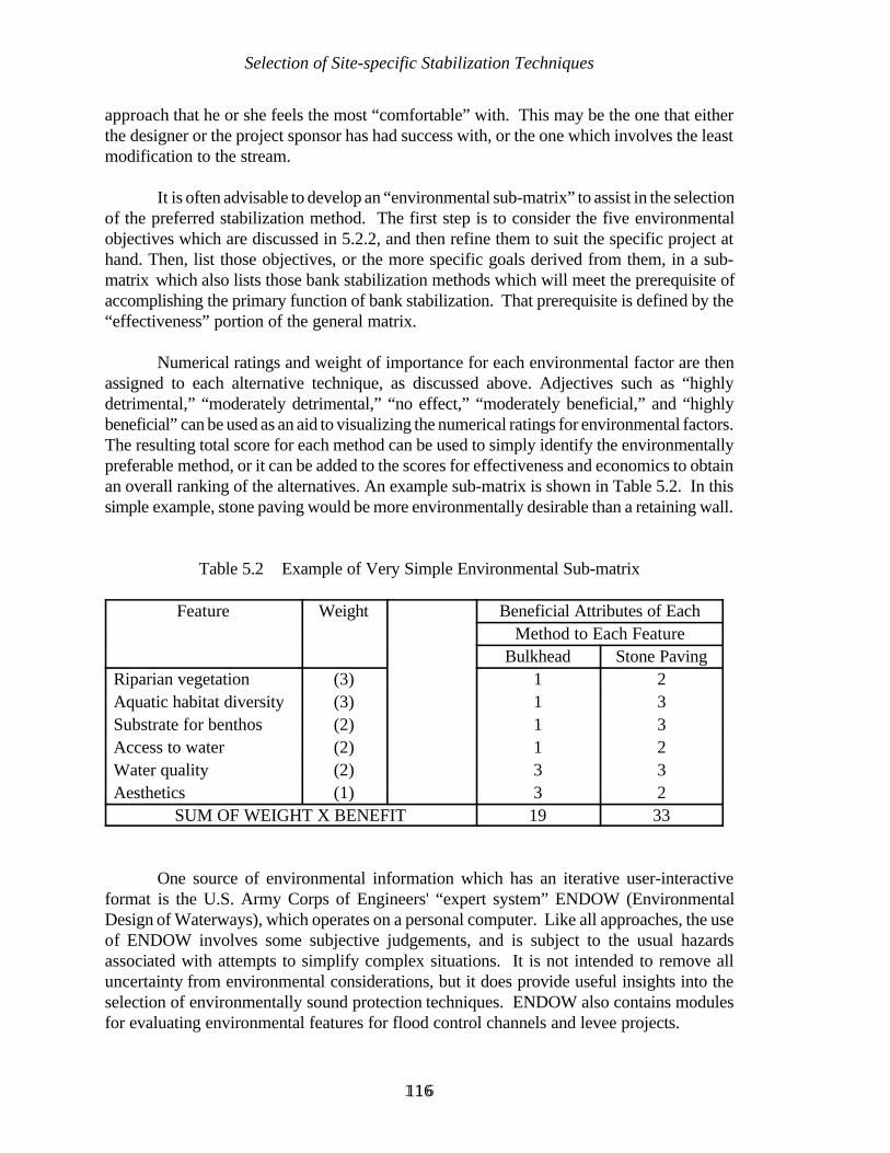
Selection of Site-specific Stabilization Techniques
116116
approach that he or she feels the most “comfortable” with. This may be the one that eitherthe designer or the project sponsor has had success with, or the one which involves the leastmodification to the stream.
It is often advisable to develop an “environmental sub-matrix” to assist in the selectionof the preferred stabilization method. The first step is to consider the five environmentalobjectives which are discussed in 5.2.2, and then refine them to suit the specific project athand. Then, list those objectives, or the more specific goals derived from them, in a sub-matrix which also lists those bank stabilization methods which will meet the prerequisite ofaccomplishing the primary function of bank stabilization. That prerequisite is defined by the“effectiveness” portion of the general matrix.
Numerical ratings and weight of importance for each environmental factor are thenassigned to each alternative technique, as discussed above. Adjectives such as “highlydetrimental,” “moderately detrimental,” “no effect,” “moderately beneficial,” and “highlybeneficial” can be used as an aid to visualizing the numerical ratings for environmental factors.The resulting total score for each method can be used to simply identify the environmentallypreferable method, or it can be added to the scores for effectiveness and economics to obtainan overall ranking of the alternatives. An example sub-matrix is shown in Table 5.2. In thissimple example, stone paving would be more environmentally desirable than a retaining wall.
Table 5.2 Example of Very Simple Environmental Sub-matrix
Feature Weight Beneficial Attributes of EachMethod to Each Feature
Bulkhead Stone PavingRiparian vegetation (3) 1 2Aquatic habitat diversity (3) 1 3Substrate for benthos (2) 1 3Access to water (2) 1 2Water quality (2) 3 3Aesthetics (1) 3 2
SUM OF WEIGHT X BENEFIT 19 33
One source of environmental information which has an iterative user-interactiveformat is the U.S. Army Corps of Engineers' “expert system” ENDOW (EnvironmentalDesign of Waterways), which operates on a personal computer. Like all approaches, the useof ENDOW involves some subjective judgements, and is subject to the usual hazardsassociated with attempts to simplify complex situations. It is not intended to remove alluncertainty from environmental considerations, but it does provide useful insights into theselection of environmentally sound protection techniques. ENDOW also contains modulesfor evaluating environmental features for flood control channels and levee projects.

Selection of Site-specific Stabilization Techniques
117117
A troubling irony will become apparent in the course of using the matrix approach.Even though this is a quantitative and objective procedure, one can arrive at differentconclusions by changing the weight of the various factors and/or changing the ratings of thedifferent stabilization methods, while still remaining within a reasonable range of values ofweights and ratings. This irony illustrates that the procedure is not a substitute forengineering judgement, but is merely a catalyst for engineering judgement, a mechanism forconsidering all relevant factors and all appropriate alternatives, thus reducing the probabilityof a major oversight.

Selection of Site-specific Stabilization Techniques
118118

119119
CHAPTER 6
GENERAL PRINCIPLES OF EROSION PROTECTION
This chapter provides general guidance for the design of the erosion protectioncomponent of riverbank stabilization work. The discussion in this chapter will also help inunderstanding the basis for the approach to selecting the preferred stabilization method, whichwas presented in Chapter 5.
The great variation in site conditions and project constraints, and the almost infinitepossible combinations of materials and design details of the alternative methods of erosionprotection, make a “cookbook” approach to design impractical. A committee of theAmerican Society of Civil Engineers reported in 1965 that “Because of the complex natureof alluvial streams, design of channel stabilization works is based largely on experience” andthis is still the case. As Simons and Li (1982) state, “...handbook-type analyses and designs[for river training and bank stabilization] usually lead to poor solutions of specific problems.”Hemphill and Bramley (1989) similarly state “...good design practice necessarily involvesjudgement and experience, and [we] can only draw attention to the various aspects whichneed to be taken into consideration or on which expert advice should be sought.”
This chapter seeks to assist the designer's judgement by providing a synthesis ofexperience. Additional information on specialized topics can be obtained from the referencescited in this text.
To present guidance in a structured fashion, the chapter is divided into the followingsix sections:
Applied Geomorphology;Hydraulics;Toe Protection;Surface Drainage;Manufacturer's Recommendations; andSafety Factor.
This list, along with environmental considerations (see 4.2 and 5.2) can be used as a“checklist” to insure that the designer has not overlooked any major factors. For some
General Principles of Erosion Protection
120120
stabilization methods, one or more factors can be quickly dismissed. For example, provisionfor surface drainage is not usually required for “indirect” protection methods, whilemanufacturer's recommendations apply only to commercial products.
At this point, a caveat which has been inferred previously in Chapters 4 and 5 mustbe reiterated: to arrive at the point of designing a site-specific bank stabilization project, thedesigner must make one of the following judgements:
that the fluvial system is in equilibrium;
that system instability exists, but that channel changes will not significantlyaffect the bank stabilization project, or that the bank stabilization can bedesigned to accommodate such changes; or
that system instability exists, but that it will be corrected in conjunction withsite-specific bank stabilization if appropriate.
In practice, the problem of making an assumption regarding system instability is notas difficult as might first be imagined. In practice, the first two conditions often apply, andsuccessful bank stabilization projects have been built without the designers taking intoaccount the possibility of system instability. Ideally, however, any element of chance can beremoved from project design by first applying the principles discussed in Chapters 2 and 3 tocorrectly determine the causes and mechanisms of bank retreat.
6.1 APPLIED GEOMORPHOLOGY
This section deals with the integration of the understanding of stream characteristicsoutlined in Chapters 2 through 3 into the decision-making process with regard to the locationof bank stabilization works. The specific aim is to describe how best to use “applied fluvialgeomorphology” to make the following two basic decisions:
Location of the upstream and downstream limits of work
Alignment of the work with respect to the stream channel
6.1.1 UPSTREAM AND DOWNSTREAM LIMITS OF WORK
This initial design decision is based on an analysis of channel migration, aconsideration of the minimum requirement for length of bank to be protected, and otherdetailed considerations.
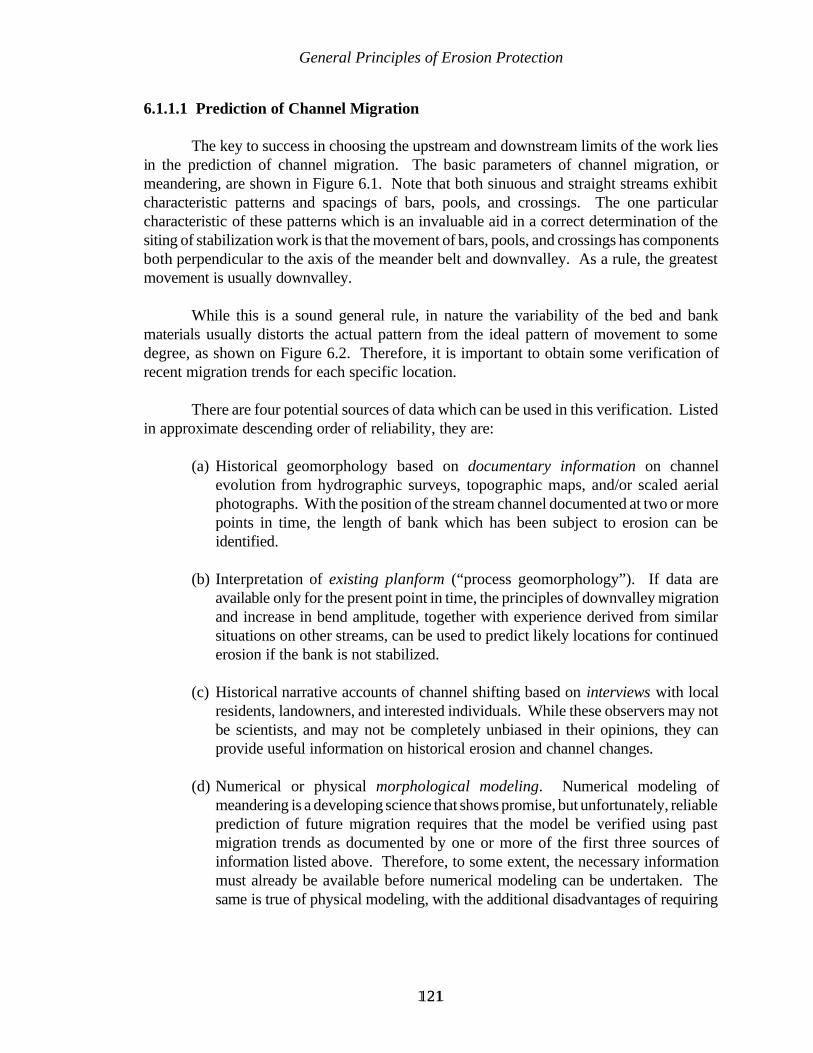
General Principles of Erosion Protection
121121
6.1.1.1 Prediction of Channel Migration
The key to success in choosing the upstream and downstream limits of the work liesin the prediction of channel migration. The basic parameters of channel migration, ormeandering, are shown in Figure 6.1. Note that both sinuous and straight streams exhibitcharacteristic patterns and spacings of bars, pools, and crossings. The one particularcharacteristic of these patterns which is an invaluable aid in a correct determination of thesiting of stabilization work is that the movement of bars, pools, and crossings has componentsboth perpendicular to the axis of the meander belt and downvalley. As a rule, the greatestmovement is usually downvalley.
While this is a sound general rule, in nature the variability of the bed and bankmaterials usually distorts the actual pattern from the ideal pattern of movement to somedegree, as shown on Figure 6.2. Therefore, it is important to obtain some verification ofrecent migration trends for each specific location.
There are four potential sources of data which can be used in this verification. Listedin approximate descending order of reliability, they are:
(a) Historical geomorphology based on documentary information on channelevolution from hydrographic surveys, topographic maps, and/or scaled aerialphotographs. With the position of the stream channel documented at two or morepoints in time, the length of bank which has been subject to erosion can beidentified.
(b) Interpretation of existing planform (“process geomorphology”). If data areavailable only for the present point in time, the principles of downvalley migrationand increase in bend amplitude, together with experience derived from similarsituations on other streams, can be used to predict likely locations for continuederosion if the bank is not stabilized.
(c) Historical narrative accounts of channel shifting based on interviews with localresidents, landowners, and interested individuals. While these observers may notbe scientists, and may not be completely unbiased in their opinions, they canprovide useful information on historical erosion and channel changes.
(d) Numerical or physical morphological modeling. Numerical modeling ofmeandering is a developing science that shows promise, but unfortunately, reliableprediction of future migration requires that the model be verified using pastmigration trends as documented by one or more of the first three sources ofinformation listed above. Therefore, to some extent, the necessary informationmust already be available before numerical modeling can be undertaken. Thesame is true of physical modeling, with the additional disadvantages of requiring
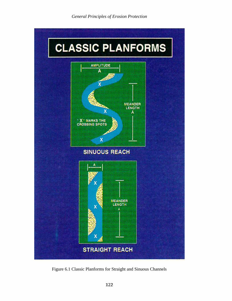
General Principles of Erosion Protection
122122
Figure 6.1 Classic Planforms for Straight and Sinuous Channels
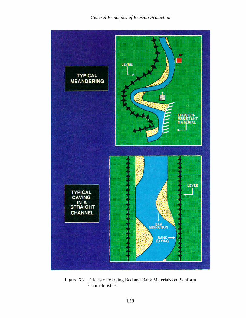
General Principles of Erosion Protection
123123
Figure 6.2 Effects of Varying Bed and Bank Materials on PlanformCharacteristics
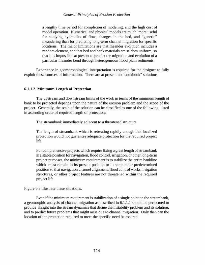
General Principles of Erosion Protection
124124
a lengthy time period for completion of modeling, and the high cost ofmodel operation. Numerical and physical models are much more usefulfor studying hydraulics of flow, changes in the bed, and “generic”meandering than for predicting long-term channel migration for specificlocations. The major limitations are that meander evolution includes arandom element, and that bed and bank materials are seldom uniform, sothat it is impossible at present to predict the migration and evolution of aparticular meander bend through heterogeneous flood plain sediments.
Experience in geomorphological interpretation is required for the designer to fullyexploit these sources of information. There are at present no “cookbook” solutions.
6.1.1.2 Minimum Length of Protection
The upstream and downstream limits of the work in terms of the minimum length ofbank to be protected depends upon the nature of the erosion problem and the scope of theproject. Generally, the scale of the solution can be classified as one of the following, listedin ascending order of required length of protection:
The streambank immediately adjacent to a threatened structure.
The length of streambank which is retreating rapidly enough that localizedprotection would not guarantee adequate protection for the required projectlife.
For comprehensive projects which require fixing a great length of streambankin a stable position for navigation, flood control, irrigation, or other long-termproject purposes, the minimum requirement is to stabilize the entire banklinewhich must remain in its present position or in some other predeterminedposition so that navigation channel alignment, flood control works, irrigationstructures, or other project features are not threatened within the requiredproject life.
Figure 6.3 illustrate these situations.
Even if the minimum requirement is stabilization of a single point on the streambank,a geomorphic analysis of channel migration as described in 6.1.1.1 should be performed toprovide insight into the stream dynamics that define the instability problem and its solution,and to predict future problems that might arise due to channel migration. Only then can thelocation of the protection required to meet the specific need be assured.
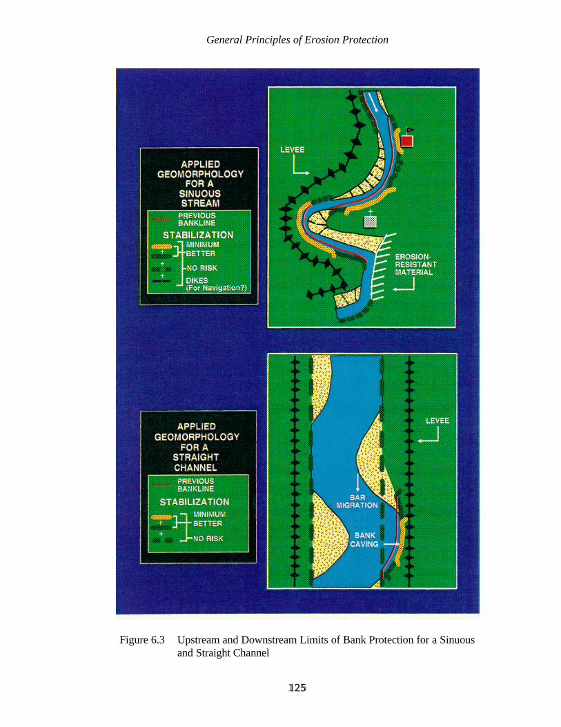
General Principles of Erosion Protection
125125
Figure 6.3 Upstream and Downstream Limits of Bank Protection for a Sinuousand Straight Channel
General Principles of Erosion Protection
126126
6.1.1.3 Other Considerations
Application of the preceding discussion to the selection of upstream and downstreamlimits of stabilization work should consider the following concepts:
(1) The downstream limit is usually more critical than the upstream limit, since thescour pools associated with the normal pool-bar pattern tend to movedownstream, and bank failure is often associated with these pools. Althoughbeginning the upstream end of work at the precise point where erosion presentlybegins carries some risk that erosion will later occur upstream of that point, costsavings may make that risk acceptable, because often a bar will migratedownstream, changing the area of erosion at that point into one of deposition.Conversely, placing the downstream end of the work at the present limit oferosion carries a high risk that the work will be outflanked by subsequent erosiondownstream of that point.
(2) Although the preceding concept applies to most situations, a caution regardingthe upstream limit should be observed: if a serious mistake is made in assessingthe future migration pattern of the stream, and the stabilization work isoutflanked at the upstream end, then subsequent deterioration of the integrity ofthe stabilization project may occur rapidly.
(3) Model tests under the Section 32 Demonstration Erosion Control Program (U.S.Army Corps of Engineers, 1981) indicated that erosion protection in a bendshould be extended downstream from the point of tangency a distance of at least1.5 times the width of the approach channel into the bend. This can be used forgeneral guidance if data on channel behavior at a specific location is unavailableor unreliable. Studies by Parsons (1960) provide similar insight.
(4) The transition from the stabilized bank to the natural bankline can be made rathersimply at the upstream limit. The details depend on the type of protection beingused, but in general a slight increase in the strength and/or a shallow “key-in” willbe sufficient for armor-type protection. Indirect protection can simply be turned,or “feathered,” into the bank, with a slight recess being good insurance.
(5) In contrast, more elaborate precautions are advisable for the transition to thenatural bankline at the downstream limit. The most important precaution is toinsure that the work is not stopped prematurely, as discussed above. Beyondthat, it is advisable to “key-in” and/or increase the strength of armor revetment.For indirect bank protection works, a pronounced “tuck-in” should be provided,perhaps with a liberal application of stone if conditions are severe. Thealternative is to be prepared to reinforce the work at some time in the future ifscour at the downstream limit threatens to outflank the protection. Such anapproach may be sound if project authority, rate of erosion, and the potentialconsequences of miscalculation allow it.
General Principles of Erosion Protection
127127
(6) Analysis of the present conditions and prediction of future channel migrationshould take into account the magnitude of flows that occurred prior to the siteinspection, or that occurred during the time period spanned by surveys or aerialphotos that are being used for analysis. High flows tend to attack the bankfurther downstream, and low flows farther upstream, because meander wavelength is directly proportional to discharge. The stream integrates the totalhydrograph over the long-term, but short-term observations may be distorted byextreme events. Therefore, if the period of observation is weighted toward lowflows, the long-term attack may be farther downstream and more severe thancurrent observation would indicate. High flows during the period of observationmay have the opposite effect.
6.1.1.4 Special Considerations for Braided Streams
Protection works on braided streams may need to extend upstream and downstreamfrom the active erosion, because bars, chutes, and pools move more rapidly and much lesspredictably than in meandering streams. Often bank erosion is associated with meanderingtendencies of major anabranches, and the likely pattern of attack can be fairly well predictedusing the rules of downvalley and lateral migration for alluvial bends. However, in other casesbank erosion may be caused by less predictable impinging flow in side channels. The mostefficient approach on a braided stream where bank erosion is associated with anabranch flowwhich impinges against the bank at sharp angles may be one of the following:
Treat problem areas as they arise by constructing spot stabilization as thestream attacks first one spot, then another.
Temporarily divert impinging flows, either by excavating a new channel,building temporary dikes of streambed material, or using floating“breakwaters” to absorb the brunt of the impinging flow. However,environmental aspects of construction activity in the streambed may not beacceptable.
If long-term stabilization is required on a braided stream, and project constraintspreclude installing bank protection periodically as the channel changes, an adequate solutionmay require the construction of continuous protection on both sides of its “braid belt.”Trenchfill or windrow revetment is well-suited for this application.
General Principles of Erosion Protection
128128
6.1.2 CHANNEL ALIGNMENT
The preferred choice for the alignment of a stabilized channel is straight-forward.However, exceptions to the preferred choice are rather common. Following is a discussionof the preferred choice and some exceptions.
6.1.2.1 Preferred Choice
The preferred alignment in most cases is to accept the existing general channelalignment, because significantly changing the alignment makes it more difficult to predict theultimate equilibrium planform and channel geometry. This uncertainty carries risk not onlyfor the success of the work, but also for assessing the potential for detrimental effects causedby the work.
Relocation of a bank which is to be armored or vegetated requires costly andtime-consuming excavation and/or filling. Also, the environmental effects of removing anddisposing of large amounts of bank material may be unacceptable. The work would bevulnerable to damage from high flows during construction, causing both contractual andengineering difficulties. Banks constructed totally of fill material would be highly susceptibleto settlement and scour even after being armored, unless the fill is well-compacted duringconstruction and a well-designed filter is provided. Both of these measures would addsubstantial cost and difficulty to the project. Also, vegetation may not provide adequateprotection for banks newly constructed of fill material, which would further limit the potentialfor a cost-effective and environmentally acceptable design.
Indirect protection methods (Chapter 8) can more easily be used to modify theexisting alignment, but the same basic principle applies - the existing stream, especially if itis in a condition of dynamic equilibrium and has developed a stable alignment, so changingthat alignment may generate system-wide instability and should be approached with caution.
6.1.2.2 Possible Exceptions
Exceptions to the preferred choice of accepting the natural alignment are sometimesjustified in situations other than that of limited foreshore. Three potential exceptions are:
(1) At very sharp bends;(2) Highly irregular banklines; and(3) Straight reaches with unstable planforms.
Channel realignment in these situations is more likely to be required on projects withnavigation aspects than on projects with only bank stability aspects.
Most alluvial rivers have a range of values of radius of curvature, meander wavelength, or in straight reaches, pool and bar spacing, within which the planform is dynamically
General Principles of Erosion Protection
129129
stable. Therefore, any channel realignment project undertaken to alter one of the situationslisted above should avoid extreme values of those variables. Determining the preferred rangeof values for a particular stream will be especially difficult if the stream has recently aggradedor degraded, and the planform is still adjusting, especially if the threshold between meanderingand braided has been crossed.
(1) Specific considerations regarding channel realignment in very sharp bends are asfollows:
Realignment of the channel in a very sharp bend may be justified in order toprevent a major channel avulsion in the future. Such an avulsion, in the form ofa natural cutoff or development of a major chute channel through the point barof the bend, might cause serious bank stability problems in downstream reaches.
The radius of curvature of the bend can be increased, that is, the bend madeflatter, either by using indirect protection, or by making a well-planned cutoff.An increase in bend radius may result in a decrease in maximum channel depthin the bend, thus improving bank stability.
Use of an indirect protection method in this situation will ideally result in themaximum depth of scour occurring farther away from the toe of the bank thanunder natural conditions, thus improving bank stability with respect to massfailure.
The disadvantages of using an indirect protection technique in this situation arethat (a) much of the construction has to be done in the deepest part of theexisting channel, thus increasing the cost and difficulty of construction; and (b)it may be necessary to excavate the opposite point bar to relieve the initialconstriction caused by the stabilization structures. Otherwise, local velocities,and perhaps even backwater effects in extreme cases, may be unacceptably highin the interim period that it takes the channel to adjust to the work.
Realigning the channel by constructing a cutoff across the neck of the bendamounts to the channel relocation approach discussed in Chapter 4. Erosion inthe bend can be eliminated by a cutoff, but erosion will continue elsewhere ifchannel migration is characteristic of the stream. Therefore, even a cutoff mayneed to be accompanied by bank protection, and the prediction of subsequentlong-term channel behavior is more uncertain in the presence of a cutoff.
Detailed considerations for designing a cutoff are presented by Petersen (1986).
(2) If the natural bankline alignment is highly irregular, and it is determined that amore uniform flow and planform would best accomplish project purposes, thenthe bankline can be smoothed either by (a) placing indirect protection on asmooth alignment riverward of the natural bankline, as discussed above for a

General Principles of Erosion Protection
130130
sharp bend; or by (b) placing trenchfill or windrow revetment landward of theprotruding bankline points, and allowing the stream to erode the irregularitiesaway. This approach offers simple design and construction, since the operationis removed from the active channel. However, the bank retreat which occursbefore the channel reaches the stabilization structure may not be greetedenthusiastically by property owners. Conversely, if erosion is slower thananticipated, a navigation project with a schedule to meet may require costlydredging of the uneroded foreshore.
(3) In a straight reach with an unstable planform, or on a braided stream, it may bedesirable to increase the sinuosity of the main channel in order to stabilize thelocation of scour pools and bars. This can also provide better channel alignmentand a deeper channel for navigation. However, an accurate assessment ofchannel migration tendencies, the stable range of values for pool and bar spacing,and the ratio of radius to width, is especially critical in this situation. Such arealignment often involves both armor revetments and indirect protection incombination, depending upon the bank and channel topography along theproposed realigned bankline.
6.2 HYDRAULICS
Having used applied fluvial geomorphology to decide on the location of bankprotection work, the next step is to apply a fluvial hydraulics analysis to decide how deep,how high, and how strong to make the work. The concepts of fluvial hydraulics presentedin Chapters 2 and 3 apply to the following factors:
Design discharge;Tractive force and permissible velocity;Secondary currents;Variations in river stage;Top elevation of protection;Wave, vessel, and ice forces; andPrediction of toe scour.
6.2.1 DESIGN DISCHARGE
It is important to recognize the distinction between design discharge and dominantdischarge. Design discharge usually refers to an extreme event, and is often used inconnection with flood control channel analyses. A tractive force or velocity associated withthe design discharge is also commonly used to compute stone size for riprap armor (see6.2.2), and a similar approach can be used to design many commercially available armormaterials. The design discharge can be defined quite precisely using hydrologic analyses.
General Principles of Erosion Protection
131131
In contrast, the discharge which governs the long-term behavior of a stream, and thusmany aspects of the design of bank stabilization work, is exceeded rather frequently, but thereis no consensus on how to best define it. It is variously called the “dominant” or“channel-forming” or “effective” discharge, but is in fact an abstract quantity because innature no single steady discharge will reproduce the morphological and sedimentary featureswhich are formed by the varying discharge of a natural stream. However, it is oftenconsidered to be about equal to bankfull discharge on streams that are neither aggrading ordegrading.
In practical terms, the design discharge is the flow which would stress bankstabilization work most severely over a short period of time. It is desirable to quantify it andto use it to size the armor layer if we are using an armor technique for which criteria exist.However, for many other protection methods, determination of a design discharge will beacademic because no criteria exists to apply it.
6.2.2 TRACTIVE FORCE AND PERMISSIBLE VELOCITY
Tractive force and permissible velocity are two parameters that are commonly usedto quantify stress on the boundaries of a channel, whether the boundaries are formed insediment or consist of a protective armor. The highest stresses usually occur under the designdischarge. Except for riprap and some manufactured products, little precise guidance existsregarding the limiting tractive force for erosion protection materials. For materials for whichno precise guidance exists, demonstrated performance under comparable conditions is the bestguide.
6.2.3 SECONDARY CURRENTS
Flow at channel bends in meandering channels and alongside bars and confluences inbraided channels is sharply three-dimensional. Velocities in the plane normal to the axis ofprimary or longstream flow are termed secondary currents and coherent patterns of thesecurrents, termed secondary cells, can influence the distributions of primary velocity andtractive force that erode the banks.
However, the patterns of secondary cells, especially close to eroding banks, are poorlyunderstood. It is known that plunging flow close to the outerbank in natural meanders oftenpromotes deep toe scour and that the sweeping effect of inward directed secondary currentsnear the bed promotes point bar growth at the inner bank.
These processes are important to the growth of meanders, but more to the point here,they are fundamental to the mechanisms of bank failure, and influence the effectiveness ofmany types of bank and channel stabilization work. Unfortunately, secondary currents canusually be addressed in design only indirectly, by letting the stream integrate them into itsbehavior, along with all the other geomorphic, hydraulic, and geotechnical processes.
General Principles of Erosion Protection
132132
6.2.4 VARIATIONS IN RIVER STAGE
Although this is, strictly speaking, a hydraulic variable, its primary application todesign is geotechnical, since the susceptibility of the bank to mass failure, leaching, andpiping, is to some degree a function of the rate of drawdown of the water level. Themagnitude and timing of the variation also influences the constructability of differenttechniques.
6.2.5 TOP ELEVATION OF PROTECTION
A major design parameter concerns the determination of the elevation to whicherosion protection works should be constructed. The most conservative approach for armorrevetments is to set the top elevation at design flowline plus a margin for freeboard. Thisequates to the top of the levee for leveed channels, or to the top of the riverbank where thereare no levees, or where they are well protected by vegetation or by distance from the channel.In many situations, this criteria is too conservative and would result in excessive cost andreduced environmental suitability. Unless erosive velocities are believed to exist at highelevations, and the consequences of even minor erosion are unacceptable, considerationshould be given to designing the top elevation of protection at a more frequently occurringflowline. Other factors that should be considered in order to decide on the lowest and leastcostly, yet effective, elevation are shown in Figure 6.4 and are listed below:
Stage duration;Severity of overbank flow;Erodibility of upper bank material;Type of protection and slope of the bank; andConsequences of failure.
These factors also influence the top elevation of indirect protection, although the mostconservative elevation for indirect protection is normally considered to be the elevation of topof the river bank rather than the elevation of the design flood flowline.
Little quantitative guidance is available for applying these factors. An exception tothis occurs in situations where the primary purpose of the work is protection against waveaction. In those situations, fairly rigorous procedures have been developed to compute waveheight and run-up for use in designing top elevation of protection. This is usually not the critical condition for streambank protection, but the references provided in 6.2.6 providespecific guidance for situations where it is the critical condition. In other cases, merelyconsidering qualitatively the factors listed above and discussed below is an aid to intelligentdecision making.

General Principles of Erosion Protection
133133
Figure 6.4 Top Elevation of Protection
General Principles of Erosion Protection
134134
6.2.5.1 Stage Duration
The period of time that river stages exceed a given elevation is important for tworeasons:
It determines how long the upper bank will be subject to potentially erosivecurrent.
It determines the lowest elevation at which riparian vegetative growth will notbe impeded by inundation. This is a factor in determining the minimum topelevation for armor revetment when it is used in combination with vegetationfor upper bank protection.
Unfortunately, there is no published guidance that relates the top elevation ofprotection works with stage duration. However, an example of terminating armor protectionbelow the elevation of the design flood flowline is provided by riprap upper bank protectionon some portions of the Lower Mississippi River. It is routinely terminated at a flowlineelevation exceeded 5 to 10 percent of the time. On small streams in north Mississippi, the topof the rock in longitudinal stone toe protection (see section 7.1.4) routinely corresponds toa stage that equaled or exceeded about 1 to 5 percent of the time.
6.2.5.2 Severity of Overbank Flow During Floods
The velocity of flow at the interface of the protection and the unprotected bank duringfloods is influenced by channel alignment, local variations in the elevation of the bank, and theextent of vegetative cover on the upper bank and overbank. Local bankline irregularitieswhich cause a convergence of streamlines, accompanied by higher velocities, can also playa role. The most severe conditions occur at the necks of sharp bends with relatively low bankelevations and little overbank vegetation. Also, the downstream half of sharp bends is wherehighest velocities against the bank and in the overbank usually exist. Therefore, a higherelevation of protection may be prudent there.
6.2.5.3 Erodibility of Upper Bank Material
This factor is best evaluated by on-site observation. The rate of historic banklinerecession alone is not a totally reliable indicator of erodibility of the material in the zone beingconsidered for the top elevation of protection. The material in the upper bank may be veryerosion resistant, but still fail from toe scour and subsequent mass failure. General guidanceon the erodibility of different bank materials is available, and can be used if experience withparticular site conditions is lacking. The most erosive soils are fine sands and silty sands, andthe least erosive are clay and coarse gravels.
General Principles of Erosion Protection
135135
Erodibility of the upper bank material is also an important factor in selecting the topelevation of indirect protection structures. If the upper bank is highly erodible, then thestructures should be high enough to reduce near-bank velocities during most flows. If theupper bank is more erosion-resistant, then the structure needs to be only high enough toinduce deposition in front of the bank, especially if the duration of high flows is short, thestream carries a large suspended sediment load, and/or if vegetation can be expected tocolonize the area of induced deposition.
6.2.5.4 Type of Protection and Slope of the Bank
These two factors act together to affect the near-bank velocity at the top of armorprotection. The rougher the armor and the flatter the bank slope, the lower the velocity atthe top of the armor will be, and the lower down the bank the armor can be terminated. Also,flatter slopes are more conducive to vegetative growth, thus upper bank erosion in the formof “shelving” behind the armor will be more likely to be arrested by subsequent volunteervegetative growth, if climate and soils are favorable.
Since rigid armor cannot adjust well to local scour, it should normally be carried toa higher elevation than adjustable or flexible armor. The alternative to carrying it to a higherelevation is to use adjustable or flexible armor above the rigid armor as a means oftransitioning to a non-erosive elevation or to the elevation where vegetative protection willbegin.
To some degree, the type of protection determines the amount of design effort thatcan reasonably be expended to optimize the top elevation, and the potential savings fromdoing so. If the protection material is relatively inexpensive, the potential savings from alower elevation will be relatively small, and taking a considered risk in terminating it at alower elevation will be less attractive.
6.2.5.5 Consequences of Failure
This may well be the dominant factor in setting the top elevation of your protectionwork, especially if the other factors are poorly defined. Since this is an integral componentin determining the overall “safety factor” against failure of the work, it is discussed in 6.6.
General Principles of Erosion Protection
136136
6.2.6 WAVE, VESSEL, AND ICE FORCES
These forces are seldom the dominant cause of bank failure on most streams.Therefore, they do not usually present the critical design case. However, in some situationsthe erosion induced by these forces, and the effects of these forces on bank protection works,can be highly visible and significant. There are several references that address design ofprotective works in detail, and numerous more specialized papers and publications. Twogeneral references that provide an excellent introduction to the topic are U.S. Army Corpsof Engineers (1984) and Hemphill and Bramley (1989).
6.2.7 PREDICTION OF TOE SCOUR
Degradation is a long-term, large scale process, but toe scour is usually associatedwith the impacts of high flows over short reaches of channel.
This chapter deals with situations where the design of bank stabilization proceedsunder the assumption that the channel will not suffer significant future degradation. Similarly,the various methods for predicting toe scour deal with local scour as a separate process fromdegradation.
The general approaches to predicting toe scour are:
Analytical, using one or more of the relationships that have been proposed byvarious researchers;
Empirical, using experience from similar situations; and
Modelling (numerical and/or physical).
Illustrating the uncertainty of analytical approaches, Copeland (1983) cites sevendifferent equations proposed by as many researchers for the specialized case of predictingscour at spur dikes. There is disagreement even as to the significant factors involved, andcertainly disagreement in the results.
As a result of the limitations of analytical approaches, an empirical approach is oftenconsidered to be more reliable. However, adequately documented experience may beunavailable in particular situations. In such cases, the designer must apply one or more of theanalytical or modelling approaches.
The limitations to modelling that were discussed with respect to channel migrationalso apply to the prediction of toe scour, although not to as great a degree. Two-dimensionalnumerical models are required, and three-dimensional numerical models would be preferableif available. Physical models must be large scale.
General Principles of Erosion Protection
137137
The degree to which these three techniques can be applied is a matter of judgement,and will depend on time and funds available for the analysis, the scope of the project, theconsequences of an inaccurate estimate of toe scour, and upon the personal and institutionalexperience which can be brought to bear on any specific problem.
6.3 TOE PROTECTION
Toe protection is essential to the success of bank protection work, although it maynot be a massive element of the work if the exposure to scour is relatively mild. Once aprediction of the amount of toe scour to be expected has been made, a variety of methods areavailable to accommodate it in the design. In this section, general guidance for all types ofprotection is provided.
6.3.1 BASIC OPTIONS
There are two basic options. First, to “dig it in” by extending the toe of theprotective works into an excavation at or below the predicted scour depth, or at the elevationof a non-erodible material, if such material is present within the practical limits of excavation;or second, to “let it self-launch” by designing the work so that, as scour occurs, theprotective material can launch or flex downward sufficiently to prevent the scour frommoving inshore and causing geotechnical instability of the bank.
The “dig it in” approach is most often used with an armor revetment. Its primarydisadvantage is that excavation in a flowing stream, and precise placement of an armormaterial in the excavation, is often difficult and costly, and sometimes impossible. Ten feetis sometimes used as a rule of thumb for the limit of conventional excavation techniquesunderwater. Beyond that depth, either dredging or dewatering with a cofferdam may berequired for excavation and armor placement.
Sheet-pile retaining walls and pile-supported indirect protection structures which aredesigned to withstand maximum scour can be considered special cases of the “dig it in”approach.
The “self-launching” approach offers economy and ease of construction by allowingthe stream rather than the contractor to perform the excavation. However, it does require alarger volume of material in the toe section than if the toe is placed in an excavation, since thelaunching process may be irregular. As a result, the cost of material may in some cases negatesavings in operational cost. Therefore, if site conditions permit easy mechanical excavationto the predicted scour depth, the “dig it in” approach may be the least costly overall.
The “self-launching” technique also offers the considerable advantage of providing abuilt-in scour gauge, particularly if the top of the launching section is visible above water. Ifit is underwater even at low stages, it can be surveyed by accurately located soundings. If it

General Principles of Erosion Protection
138138
appears that the toe section is launching more than expected, it can be reinforced simply byplacing additional material at the riverward edge of the remaining section.
With either approach, stone is often chosen for the toe protection material, even ifanother technique is selected for the remainder of the armor or structure, because stone toeprotection can be precisely and confidently designed for almost any application.
6.3.2 SPECIFIC GUIDANCE FOR VARIOUS TECHNIQUES
Application of the basic approaches to specific types of work is discussed in thefollowing paragraphs.
6.3.2.1 Stone Armor
Guidance can be found in Section 7.1.1.
6.3.2.2 Other Self-adjusting Armor
Either dig it in, or use the self-launching technique. The required toe volume for self-launching can be computed the same way as for stone armor. If the self-launching approachis to be used where predicted scour is more than a few feet, then stone is recommended forthe toe material.
6.3.2.3 Rigid Armor
Rigid armor should either extend to the predicted scour depth, be combined with aself-launching technique with required toe volume computed the same way as for stonearmor, or incorporate a flexible mattress at the toe.
6.3.2.4 Flexible Mattress
Similarly, a flexible mattress can be installed to the predicted scour depth, or extendedriverward of the toe of the bank by a horizontal distance at least twice the predicted depth ofscour. Where appropriate, these guidelines may be superseded by the manufacturer'srecommendations. If more than a few feet of scour is predicted, then the use of aself-launching stone toe should be considered, particularly if it will not be feasible to monitortoe scour frequently, or to reinforce the toe if required.
General Principles of Erosion Protection
139139
6.3.2.5 Dikes
The provision of toe protection for dikes is a more complex problem than that forarmor revetments. The complexity arises when trying to distinguish among three cases:
(1) General toe scour which immediately endangers the overall stability of the bankand threatens to flank or fail the dike system.
(2) Local scour which can threaten the integrity of part of a dike, and whichultimately may fail local portions of the bank.
(3) Local scour which may cause minor damage to a dike or minor bank instability,but which can be accepted.
In practice, it is difficult to separate these three processes. Conceptually, however,case (1) must be prevented, and case (2) must be addressed if the consequences of itoccurring are high. Acceptance of case (3) is inherent in the choice of dikes as the methodof erosion control.
The alternative toe protection treatments, which can be used separately or incombination, are to:
Extend the dikes into the channel to move general scour far enough awayfrom the bank to prevent major geotechnical instability.
Provide separate protection at the toe of the bank with an adjustable armor orflexible mattress. With this approach, the dikes will limit the velocity andassociated general scour near the bank, theoretically allowing a less substantialtoe protection than without dikes. This approach may not be cost effectivefor preventing general scour, since the effect of dikes on general scour cannotbe reliably predicted, requiring a more conservative design for the separate toeprotection than is theoretically necessary. However, it is often used to protectagainst local scour induced by the dike itself.
Provide separate protection riverward of the bank toe, perhaps along a lineconnecting the ends of the dikes. This is a conservative, but costly approach,which may negate the cost advantage that dikes might otherwise provide. Inthe extreme case, this approach would more properly be termed a type ofretard. In this case the dikes would simply serve as tiebacks, and would bethe secondary component of the work.
Some permeable dike designs, such as tire-posts and “Palisades” (a commercialproduct) allow components of the structure itself to be displaced downward, maintainingcontact with the bed as scour occurs. With these designs, the same cautions that are statedbelow for flexible retards are applicable.
General Principles of Erosion Protection
140140
If impermeable dikes are constructed of a material such as stone, which will launchinto a developing scour hole, the size of the scour hole will tend to be self-limiting. However,impermeable dikes are often less effective in inducing deposition than permeable dikes, andare likely to produce more concentrated flows and higher velocities locally, which tends tooffset the positive effect of self-launching.
6.3.2.6 Retards
For rigid retards, such as non-adjustable fencing or piling, some designers assumethat the impedance to flow provided by the structure, and subsequent landward depositionof sediment, will prevent toe scour from endangering bank stability. Thus they make nospecific provision for limiting toe scour. This approach is sometimes successful, but it is notrecommended unless the following conditions are met:
Pile penetration and size are designed for the condition of maximum predictedscour;
The structure will be monitored frequently and reinforced if necessary;
Suspended sediment load of the stream is large, so that deposition behind thestructure is likely to occur; and
The distance from the toe of the bank to the structure is at least twice thepredicted scour depth.
One of the following approaches may be more efficient and effective:
Locate the retards in a trench excavated to the predicted scour depth;
Install a self-launching toe section of stone or other material; and
Secure a flexible mattress to the riverward side of the retards
Flexible retard designs, such as jacks, tire-posts, and trees, allow part; or all of theretard structure itself to displace downward as scour occurs. Use of this technique requiressecure connections between retard units and between the retard structure and the landwardanchors, or extra penetration of piling, depending on the specific design. Allowance must bemade in selecting retard height so that the downward displacement will not leave the upperbank exposed to significant erosion during high flows. Otherwise, it may be necessary tomaintain the work by placing additional units on top as the originals units displace downward.
General Principles of Erosion Protection
141141
6.3.2.7 Other Flow Deflectors
Iowa vanes and bendway weirs are similar to dikes and retards in that they functionby inducing deposition at the bank toe rather than permitting scour to occur. Since theysignificantly alter secondary currents, rather than simply relocating the secondary currents,they should be less demanding of toe protection than dikes or retards. However, since theseare relatively new techniques, long-term field experience is not yet available.
6.3.2.8 Vegetative Bank Protection
The importance of toe protection for successful bank stabilization using vegetationcannot be overemphasized. Vegetation alone is unlikely to be successful as toe protectionunless velocities during design flows are so low that little toe scour is predicted, and climate,inundation conditions, and soils are conducive to a vigorous growth at the toe.
Selection of a toe protection technique should assume that the vegetated portion ofthe bank is in effect a rigid armor, which dictates that either a self-launching material or aflexible mattress be used at the toe. In practice, vegetation is usually used as a cost-savingor environmental feature in conjunction with a structural technique, and appropriate toeprotection will be an integral part of the design of the structural technique. Typical examplesare vegetative plantings between dikes, behind retards, and on the upper bank slope aboveone of the many armor materials.
6.3.2.9 Retaining Wall
If a retaining wall is part of the solution to geotechnical instability, then the approachto toe protection should be the same as for rigid retards. The alternative of designing the wallto be stable under maximum scour is likely to be more costly than limiting the scour. It alsointroduces the risk of a sudden, and, perhaps, catastrophic mass failure in the event ofmiscalculation of the maximum scour depth, since underdesign of toe protection is more likelyto manifest itself gradually and is more easily detected in time for remedy than is excess scourduring high flows in the absence of toe protection. Since retaining walls are often used insituations where consequences of failure are high, increasing the safety factor by using toeprotection as well as extra structural strength is advisable.
General Principles of Erosion Protection
142142
6.4 SURFACE DRAINAGE
Inadequate provision for surface drainage seldom results in complete failure of thework, but it should not be neglected as it can be a major concern to adjacent property owners.Inadequate design with respect to surface erosion gives the appearance of incompetentdesign, affecting public perception of the success of the work. Mistakes occur easily, becausethe designer's primary focus is usually on overall channel stabilization, and proper design foroverbank drainage flow outlets can be a tedious process, especially if rigorous designprocedures are to be followed.
Attention to surface drainage is even more important if the stream is degrading, andflowline lowering is anticipated, since rills, gullies, and channels draining from the floodplainwill similarly degrade if not adequately protected.
The amount of design effort which is appropriate is determined by the:
project purpose;
susceptibility of a site to surface erosion, which depends on topography,rainfall, vegetation, soil characteristics, and the type of bank stabilization tobe used;
engineering, environmental, and political consequences of erosion; and
feasibility of collecting sufficient data to permit a rigorous design.
The potential for surface erosion is best determined by identification and observationof pre-existing problems. However, the construction of bank stabilization work can make theproblem worse, as well as more noticeable, since gullies leading into the stream will no longerbe periodically destroyed by streambank caving. Freshly graded banks are particularlysusceptible to surface erosion, and natural levees and existing drainage patterns andvegetation may be disturbed by construction operations.
The basic steps in preventing erosion from surface drainage are to:
Protect all bare ground;Collect the overland flow; andProvide controlled outlets into the stream.
In the simplest situations, surface drainage occurs by sheet flow which is directedaway from the stream into a natural interior drainage channel. In this case, protection of bareground on unarmored bank slopes and in areas disturbed by construction activities is all thatis necessary. This is usually provided by vegetative treatments. Various types of chemical soilstabilizers are also available and are often effective.

General Principles of Erosion Protection
143143
If topography is such that significant amounts of surface drainage enter the channelin the vicinity of the work, it is necessary to collect the overland flow. This can often beaccomplished by small unlined ditches if drainage areas are small, slopes are flat, and the soilis erosion resistant. The ditches should usually include vegetative treatment orsoil-stabilization. If grading of the bank is part of the stabilization work, the natural leveesshould be rebuilt using material from bank grading or ditch construction, as shown in Figure6.5.
The provision of controlled outlets into the stream is sometimes a simple matter ofleaving a natural outlet undisturbed, if the flow carried by the outlet is not increased byalterations to the topography during construction. Otherwise, or if the natural outlet showssigns of instability, a lined outlet or culvert should be provided. Steep drops can beaccommodated by a drop culvert, or by providing energy dissipators at the ends of linedoutlets or culverts. The detailed design will be site-specific. Schwab et al. (1981) treat thesubject thoroughly, and Schiechtl (1980) provides information on successful techniques.More specific guidance based on site conditions can usually be obtained locally.
Rigid armor is more susceptible than most armors to undermining by surface drainageor destabilization by excess hydrostatic pressures due to the trapping of sub-surface waterbehind the armor. Therefore, special care should be taken in collecting surface water andproviding outlets into the stream. “Keying in” the top of the armor, or providing a “collar”of adjustable armor, is a common practice.
When indirect bank protection methods are used, surface drainage is often not aconsideration, since the work usually does not significantly alter existing drainage conditions.A reduction in erosion from surface drainage may be an incidental benefit of the work ifdeposition behind the bank protection structure raises the base level of existing outlets. Thismay, in fact, present a problem if deposition is high enough to block local drainage outlets.Usually, however, the only drainage treatment necessary when using indirect protection is totreat areas disturbed during construction. Treatment for local surface erosion can be designedseparately if it is a significant problem to be addressed under the project.
6.5 MANUFACTURERS' RECOMMENDATIONS
Manufacturers and distributors of the various patented or commercially availableerosion protection products may not be completely objective, since they have a vested interestin their product. However, they also want their product to perform well, and their experiencewith it is likely to be extensive. While their design methods should not be accepteduncritically, when they are supported by a service record under comparable conditions theymay obviate the need for a duplication of effort by the designer. However, the procurementpolicies of some governmental agencies may make it difficult to specify a particular productby brand name. Adding the phrase “or equal” to the specification may

General Principles of Erosion Protection
144144
Figure 6.5 Construction of Berm or Levee to Control Overbank Drainage
General Principles of Erosion Protection
145145
alleviate that difficulty, but even if a contractor's proposed substitute is considered byengineering personnel to not be “equal,” documenting that to the satisfaction of administrativepersonnel may be difficult.
6.6 SAFETY FACTOR
Most engineering analyses for the design of structures such as buildings and bridgesprovide for a “safety factor,” even when the physical laws governing the behavior of thestructure are well-defined and readily quantifiable. Because rigorous design procedures arelacking for many aspects of streambank protection, the need for a safety factor is even moreapparent. However, there is a significant difference in the analogy, in that failure of buildingsand bridges invariably carries the risk of loss of life, whereas that is often not the case withstreambank protection works. Also, the safety factor for buildings and bridges is usuallygoverned by statutes and by codes of practice, which is also not usually the case forstreambank work.
The safety factor is influenced by the:
Designer's level of experience with the protection method being usedwith the stream itself or comparable streams;
Difficulty of constructing the work to specifications;Sponsor's capabilities
to perform routine maintenanceto perform emergency reinforcement; and
Consequences of failure.
The designer's experience with the protection method and with the stream itself is ameasure of the confidence that can be placed in a prediction of the performance of the workand in a prediction of the consequences of failure of the work. The reliability of available dataon the stream also affects the level of confidence which can be placed in the designer'sassessment of the causes of bank instability.
The difficulty of constructing the work to specifications affects the possibility thatundetected construction flaws will leave vulnerable points. The timing of construction affectsthe likelihood that bad weather and high flows will extend the work period, makingincomplete portions of the work more vulnerable, especially if vegetative treatment is animportant component. Also, construction delays which result in changes in the channel maymake the design itself unsatisfactory in extreme cases.
The competence of the construction personnel and the capabilities of their equipmentare also factors. However, these factors may be unknown at the time the project is beingdesigned.
General Principles of Erosion Protection
146146
The sponsor's capability and commitment to perform routine maintenance willdetermine the probability of minor failures becoming catastrophic. The sponsor's ability toperform emergency reinforcement under difficult conditions will affect the safety factor forwork which protects important facilities such as levees. The availability of sources ofassistance during emergency conditions is also a factor. Project documentation shouldemphasize the importance of monitoring and maintenance, if appropriate.
The consequences of failure will probably be the most important single element indetermining the safety factor. This hinges on an assessment of the likelihood of loss of life,significant property damage, or severe stream channel instability if the work fails. When facedwith design decisions that cannot be resolved analytically, the consequences of failure mustbe the overriding consideration.
147147
CHAPTER 7
SURFACE ARMOR FOR EROSION PROTECTION
In this chapter, descriptive information is generally followed by a discussion ofadvantages, disadvantages, typical applications, and design considerations as appropriate. Inorder to minimize redundancy, these topics are discussed at the broadest possible level in thehierarchy of the text; in other words, aspects which are shared by all techniques are discussedat the beginning of the chapter; aspects which are shared by a group of techniques arediscussed at the group level; aspects that are peculiar to a smaller category of techniques, orto a single technique, are discussed at the appropriate level of specificity.
The extent of the discussion of specific techniques ranges from the detailed designguidance presented for riprap to a brief description for some specialized techniques.Therefore, a complete understanding of a specific technique requires perusal of all materialat a broader level in the text, as well as material peculiar to that technique.
The following paragraphs outline the general description, advantages, disadvantages,typical applications, and design considerations for most surface armor used in bankstabilization methods:
Armor is a protective material in direct contact with the streambank. Armoris often simply called “revetment,” but the more specific term “armor” is usedhere because other forms of bank stabilization, such as retards and retainingwalls, are also referred to in some regions as revetments. Armor materials canbe categorized as follows:
Stone;Other self-adjusting armor;Rigid armor; andFlexible mattress.
Advantages are: Armoring the surface of the bank is a proven approach whichcan be precisely designed for a given situation, and which provides immediateand effective protection against erosion. Also, existing or potential problemsfrom erosion by overbank drainage can be effectively addressed integrally withthe design of the streambank armor work.
Surface Armor for Erosion Protection
148148
Disadvantages are: Preparation of the bank slope is usually required, eitherfor geotechnical stability or to provide a smooth surface for proper placementof the armor. This may result in high cost, environmental damage, anddisturbance to adjacent structures. The extent of earthwork associated withan armor revetment will be especially significant if the existing channelalignment is to be modified either by excavation or by placing fill material inthe channel.
Effective subaqueous placement of armor material in deep water or whencurrent velocities are high is often difficult and costly.
Some armor materials may require special measures to mitigate undesirableaesthetic and biological characteristics.
Design considerations are: Armor must have sufficient weight and/or strengthto remain in place when subjected to hydraulic forces and impact from objectscarried by the stream. It must also prevent significant loss of bank materialfrom beneath it due to turbulence of flow or movement of groundwater.
All armor protection requires careful consideration of the geotechnicalstability of the bank, and sometimes a granular or fabric underlayment isrequired for proper interior drainage of the bank material, or to prevent lossof fine grained material through the armor.
7.1 STONE ARMOR
The following paragraphs outline the general description, advantages, anddisadvantages for most stone armors used as a bank stabilization method:
Stone armor can be placed in four general configurations, the most commonbeing a “riprap blanket.” Other forms, known as “trenchfill,” “longitudinalstone toe,” and “windrow” (referred to in some regions as “falling apron”),can be very useful in certain situations.
A stone armor usually consists of “graded” stone, which is a mixture of a widerange of stone sizes; the largest sizes resist hydraulic forces, and the smallersizes add interlocking support and prevent loss of bank material through gapsbetween the larger stones. Hand-placed stone in a smaller range of sizes isoccasionally used.
Advantages are: Because its performance has been so thoroughly analyzedby research and practical application in a wide range of conditions, stonearmor can be designed with an especially high degree of precision andconfidence. The American Society of Civil Engineers' Task Committee on

Surface Armor for Erosion Protection
149149
Channel Stabilization Works stated in 1965 that “Stone is the most commonlyused material for upper bank paving for revetment works, and in most caseshas proved superior to other materials because of durability and ability toconform to minor irregularities in the slope” (ASCE, 1965). Since that time,further development and application of manufactured proprietary armormaterials, and increasing emphasis on environmental considerations and theuse of vegetation for erosion control, has tempered that observation to somedegree. However, the favorable attributes of stone armor are not diminishedby the increasing availability of alternative materials. Furthermore, well-graded stone can often be placed without a separate underlayment material,because it provides permeability without exposing bank material. Thischaracteristic may be a crucial factor when comparing the economics ofalternative armor materials.
Disadvantages are: Stone may be more costly than other materials, dependingon its availability. It requires heavy equipment for efficient placement on largeprojects. It may be considered unaesthetic for some locations, and may notcompare favorably with other materials in some environmental circumstances.
7.1.1 RIPRAP BLANKET
Detailed discussion of and design guidance for this most common form of stone armoris provided in Appendix A. Environmental considerations pertinent to the use of riprap armorare discussed in 5.2.2.
7.1.2 TRENCHFILL
7.1.2.1 Description
A trenchfill revetment, shown in Figures 7.1 and 7.2, is simply a standard stone armorrevetment with a massive stone toe. It is normally constructed in an excavated trench behindthe river bank, in anticipation that the river will complete the work by eroding to therevetment, causing the stone toe to launch down and armor the subaqueous bank slope.
Material other than stone, such as broken soil-cement, has been used successfully andmay be less costly than stone, but careful design of the soil/cement mixture, and carefulmonitoring of the material mixing, breaking, and placing operation is required.

Surface Armor for Erosion Protection
150150
Figure 7.2 Aerial View of Trenchfill Revetment With Foreshore Material Still inPlace
Figure 7.1 Typical Cross Section of a Trenchfill Revetment
Surface Armor for Erosion Protection
151151
7.1.2.2 Advantages
A trenchfill revetment allows stabilization along a predetermined alignment, and isoften simpler to design and construct than a revetment placed on the active stream bank.
7.1.2.3 Disadvantages
Trenchfill allows erosion to continue unabated until the stream reaches it, and itsconstruction requires heavy equipment. Large areas of rights-of-way are usually required.
7.1.2.4 Typical Application
Trenchfill's most powerful use is in the following circumstances:
Where a smooth alignment of the stabilized channel is required (usually tomeet navigation criteria); and
Where rapid erosion rates, high velocities, large depths of flow, or rapidfluctuations in river stages make construction within the stream channel verydifficult.
Trenchfill has been extremely useful where these conditions exist on the Arkansas,Red, Missouri, and Mississippi Rivers. The key to successful performance is a relativelyuniform rate of launching at any given point, although uniformity of bank recession along itslength is not a prerequisite to successful performance. Therefore, it is most successful whenbank materials are predominantly noncohesive. Otherwise, additional stone may be necessary,either during construction or in later reinforcement operations, to compensate for inefficientlaunching where the underlying bank material fails by slab or rotational slips.
7.1.2.5 Design Considerations
Special design considerations are as follows:
The required thickness of the stone armor on the upper bank slope can be computedaccording to Appendix A or can be based on successful experience under similar conditions.
Stone gradation can likewise either be computed according to the guidance providedin Appendix A, or based on successful experience in similar applications. A gradation whichhas a significant amount of fine stony material has been shown by experience to be effectivein many cases without a filter or underlayment, because the fines fill the voids between thelarger stones, while still allowing the armor layer to retain adequate permeability. Such

Surface Armor for Erosion Protection
152152
gradations are sometimes called “quarry run” because little sorting is required after theblasting operation in the quarry.
The required volume of stone in the trench can be computed according to guidanceprovided in Appendix A, after the design depth of toe scour is either computed or estimatedbased on previous experience.
Design of the trench is a compromise between economics and performance. A highertrench bottom elevation reduces the volume of excavation and is less likely to requireexpensive dewatering or difficult underwater excavation. Unfortunately, it also requires agreater total volume of stone because allowing the stone to launch is less efficient than placingit to the required thickness on a prepared slope above water. Thus, a higher trench elevationrequires a larger volume of stone to protect a given height of bank, because non-uniformlaunching of the toe stone must be allowed for. The guidance for required quantity of toestone presented in Appendix A allows for this, but the fact remains that pre-placing stonecloser to its final position (that is, to a lower elevation) carries less risk than allowing it tolaunch, particularly if the bank contains cohesive material which may retreat by mass failurerather than eroding uniformly.
Because placing the stone in the trench to the lowest practicable elevation is desirable,the elevation of the bottom of the trench is sometimes specified to be as much ten feet belowthe river stage expected during the construction season, based on the assumption thatgroundwater level in the trench will be about the same as the river stage. Ten feet ofunderwater excavation is the most that is usually feasible with standard equipment withoutdewatering. Careful supervision during construction is required, and the underwater trenchshould be filled with stone in a continuous operation immediately behind the excavationfinishing operations.
A useful design refinement is to provide for a variable depth of trench, keyed to theactual river stage during construction. This permits taking maximum advantage of low riverlevels by lowering the trench so that the stone can be placed at a lower elevation. It alsoallows the trench bottom to be raised if river levels are unexpectedly high. Construction canthen continue in spite of higher stages, without putting the contractor in an untenable positionby requiring more underwater excavation or dewatering than was anticipated in the originalbid. The specifications should set an upper limit of river stage, above which operations willbe suspended. Setting this upper limit is a subjective decision, determined by the urgency ofcompleting the work, the hydrologic characteristics of the river, and the experience of designand construction personnel. The extreme case, if quick completion of the work is mandatoryin spite of high river stages, is to allow for substituting a stone windrow revetment,constructed without excavation, in place of the trenchfill.
The design slopes of the trench are established by the most critical geotechnicalcondition, depending on bank materials. This will usually be the fully launched condition.The configuration of the riverside slope of the trench is governed only by constructionconsiderations, the only requirement being that the trench remain stable long enough for the
Surface Armor for Erosion Protection
153153
stone to be placed, without creating a hazardous condition for construction personnel in theinterim.
Environmental or land use considerations may limit the area available for the disposalof material excavated from the trench. Within those limitations, excavated material can beplaced either riverward or landward of the trench. If it is placed riverward of the trench, itwill be eroded away as the river channel migrates toward the revetment, although it shouldbe placed so that it does not cause geotechnical bank failures that might affect the integrityof the stone in the trench before it launches. If it is placed landward of the trench, thegeotechnical design of the work should account for its presence, and proper routing of surfacedrainage should be provided for. Unless it is certain that natural revegetation will occur onthe disposal area within a short time after completion of construction, vegetation should beestablished as part of the construction operation. Since the disposal area will be built uphigher than the adjacent ground, habitat diversity can be improved by establishing species ofvegetation that are less tolerant of flooding than the existing species.
A portion of the excavated material can be placed so that it becomes an extension ofthe bank slope, in order to provide a greater degree of control over the direction of flows atriver stages which would otherwise overtop the natural bank. This is more likely to bedesirable in cases where the channel alongside the revetment will be used by navigation trafficthan in cases where prevention of channel migration is the only project purpose. In suchcases, the material should be semi-compacted as it is placed, and then protected from erosionas if it were part of the original bank.
7.1.3 WINDROW
7.1.3.1 Description
A windrow revetment is simply an extreme variation of a trenchfill revetment. Awindrow revetment consists of rock placed on the floodplain surface landward from theexisting bankline at a pre-determined location, beyond which additional erosion is to beprevented as shown in Figures 7.3 through 7.6.
7.1.3.2 Advantages
A windrow has the same advantages as a trenchfill, and is even simpler to design andconstruct.

Surface Armor for Erosion Protection
154154
Figure 7.3 Schematic Diagram of Windrow Revetment

Surface Armor for Erosion Protection
155155
Figure 7.5 Placement of Windrow Rock in Excavated Trench on Top Bank
Figure 7.4 Conventional Windrow Placed on Top Bank
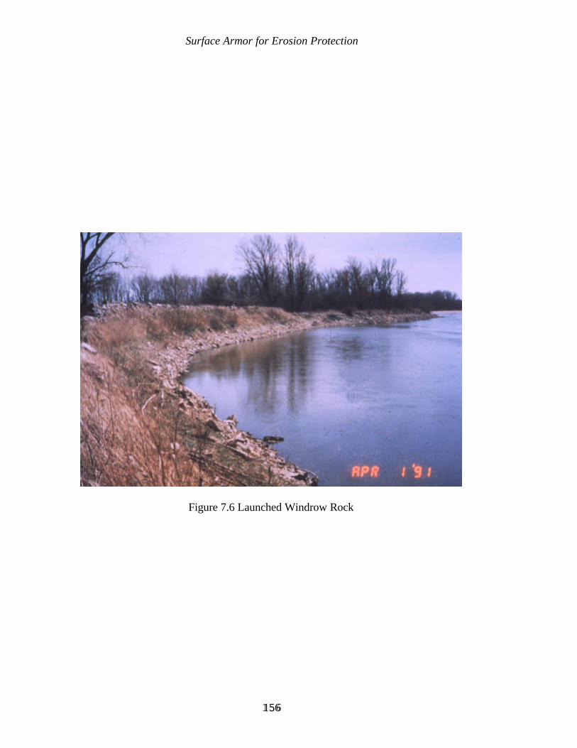
Surface Armor for Erosion Protection
156156
Figure 7.6 Launched Windrow Rock
Surface Armor for Erosion Protection
157157
7.1.3.3 Disadvantages
A windrow also has the same disadvantages as trenchfill. Also, it is rather wastefulof stone when it is placed on top of the stream bank, because the self-launching process is notas efficient when the stone must launch down the entire bank height rather than only belowthe bottom of a trench excavated to a lower elevation.
7.1.3.4 Typical Applications
Where stone or other suitable windrow material is relatively inexpensive, constructionof a windrow behind the existing bank may be cost-effective, if the simplicity of design andconstruction offset the relatively inefficient use of material. As with trenchfill, the key toefficient performance is a relatively uniform rate of launching at any given point. Therefore,sites with predominantly non-cohesive bank materials are the most suitable.
Windrow may be appropriate for emergency situations, where urgency overrides cost,there is limited time for detailed design, and high river stages and velocities prevent normalconstruction operations. The site conditions, availability of materials, equipment, and labor,in practice dictate the design, which must be performed concurrently with mobilization ofresources and the beginning of construction. The approach is to quickly feed into the streama resistant material at the critical points, continuing the operation until the crisis passes anda well-designed, permanent solution can be engineered.
7.1.3.5 Design Considerations
The design of windrow is approached in the same way as trenchfill, except that notrench design is required. Geotechnical analysis is recommended to determine if the risk ofmass bank failure during or after launching is acceptable, although it is impossible to obtainthe same degree of geotechnical safety with windrow as with more conventional methods, sothat some risk is unavoidable.
Based on laboratory model studies conducted at the U.S. Army WaterwaysExperiment Station, a rectangular shape for the windrow was found to be the best windrowshape (USACE, 1981). This shape supplies an initial surge of stone which counters thethinning effect of the scour in the toe zone of the forming revetment. The remaining portionof the windrow then provides as ready supply of stone to produce a uniform paving.However, this shape does require the excavation of a trench for placement of the stone. Thesecond best windrow shape was the trapezoidal shape. It has one advantage over therectangular shape in that no trench is needed to contain the windrow stone. This shapesupplies a steady supply of stone similar to the rectangular shape. The triangular shape wasthe least desirable shape. This shape supplies more stone initially, but the quantity of stonediminishes as the windrow is undercut.
Surface Armor for Erosion Protection
158158
The velocity and characteristics of the stream dictate the size of stone used to formthe windrow revetment. The stone must be large enough to resist being transported by thestream. Results obtained from windrow revetments constructed on the Missouri Riverindicated that small gradation stone (200-pound top size with D50 of 7 to 8 inches) was moreeffective than large gradation stone (500-pound top size with D50 of 9 to 10 inches) becausethe smaller gradation forms a more dense, closely chinked protective blanket layer than thelarger gradation. A well graded stone is important to ensure that the revetment does not failfrom leaching of the underlying bank material.
7.1.4 LONGITUDINAL STONE TOE
7.1.4.1 Description
Longitudinal stone toe is another form of a windrow revetment, with the stone placedalong the existing streambed rather than on top bank. The longitudinal stone toe is placedwith the crown well below top bank, and either against the eroding bankline or a distanceriverward of the high bank. Typical crown elevations may vary but are commonly between1/3 and 2/3 of the height to top bank.
The success of longitudinal stone toe protection is based on the premise that as thetoe of the bank is stabilized, upper bank failure will continue until a stable slope is attainedand the bank is stabilized. This stability is usually assisted by the establishment of vegetationalong the bank.
7.1.4.2 Advantages
A longitudinal stone toe has the same advantages as a trenchfill and windrow. It alsoallows for the preservation of much of the existing vegetation on the bank slope, andencourages the growth of additional vegetation as the bank slope stabilizes. An additionaladvantage is that the treatment is amenable to the planting of additional vegetation behind it.
7.1.4.3 Disadvantages
A longitudinal stone toe also has the same disadvantages as trenchfill. By definition,longitudinal stone toe protection only provides toe protection and does not directly protectmid and upper bank areas. Some erosion of these mid and upper bank areas should beanticipated during long-duration, high energy flows, especially before these areas stabilizeand become vegetated.

Surface Armor for Erosion Protection
159159
7.1.4.4 Typical Applications
Longitudinal stone toe protection is especially suitable where the upper bank slope isfairly stable (due to vegetation, cohesive material, or relatively low flow velocities), anderosion can be arrested by placing a windrow along the toe of the bank. This avoids thewasted effort of disturbing, then rearmoring, an existing stable slope. Small or ephemeralstreams are especially suited to this approach.
The longitudinal stone toe technique may be appropriate where the existing streamchannel is to be realigned, although for maximum effectiveness the top elevation of the stonemust be high enough that it is not overtopped frequently. In this application, it actuallyfunctions as a retard.
7.1.4.5 Design Considerations
There are basically two variations of the longitudinal stone toe. These will be referredto as longitudinal peaked stone toe protection, and longitudinal stone fill toe protection.Design consideration for these two stabilization measures are discussed below.
Longitudinal Peaked Stone Toe Protection. An efficient design for a longitudinalstone toe is to simply specify a weight or volume of stone to be placed per unit length ofstreambank, rather than to specify a given finished elevation and cross-section dimensions.This basically results in a triangular shaped section of stone placed along the toe of thestreambank. This type of protection is commonly referred to as a longitudinal peaked stonetoe protection (Figures 7.7 and 7.8). A primary attraction of this treatment is its simplicity.Extensive surveys and analysis during design and construction would reduce that attraction.Since the volume of stone required at each section is determined by the estimated scourdepth, simply specifying a volume or weight is all that is required. In the small streams ofnorth Mississippi, longitudinal peaked stone toe protection placed at a rate of 1 to 2 tons perlinear foot of streambank has proven to be one of the most successful bank stabilizationmeasures used in that area. This generally results in a height of stone between 3 and 5 feethigh above the streambed. A “typical” cross-section can be specified on the drawings, alongwith a relatively smooth alignment to fit site conditions. During construction, the selectedalignment for the structure is flagged, and increments of length are measured as appropriatefor the size of delivery vehicles or placement buckets. Design, bidding, and supervision ofconstruction is, therefore, greatly simplified.
With longitudinal peaked stone toe protection, the establishment of vegetationlandward of the structure is a critical component for a successful project. Consequently, it isimportant to maintain as much of the natural vegetation as possible. If at all possible, theconstruction site should be approached and the construction work accomplished from theriverward side of the bank to leave the existing upper bank vegetation undisturbed.
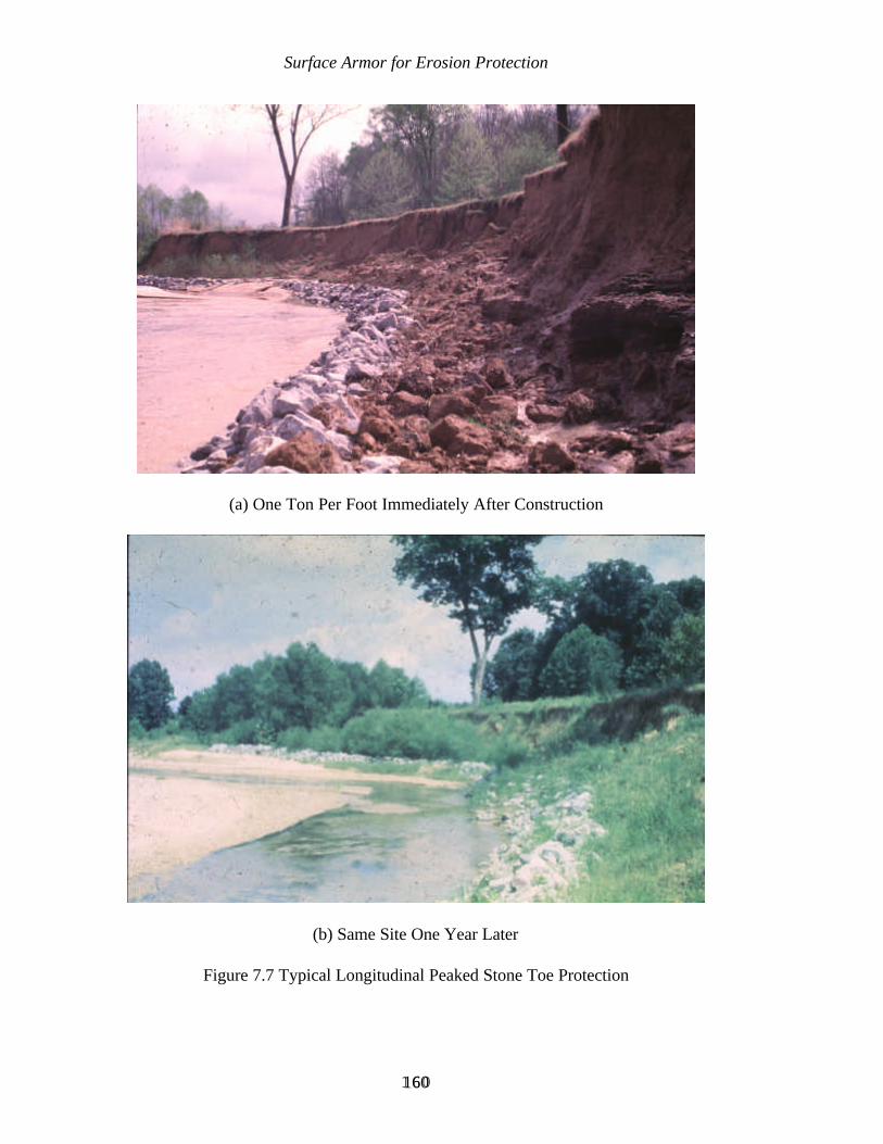
Surface Armor for Erosion Protection
160160
(a) One Ton Per Foot Immediately After Construction
(b) Same Site One Year Later
Figure 7.7 Typical Longitudinal Peaked Stone Toe Protection
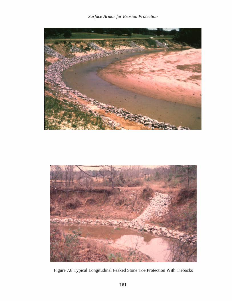
Surface Armor for Erosion Protection
161161
Figure 7.8 Typical Longitudinal Peaked Stone Toe Protection With Tiebacks

Surface Armor for Erosion Protection
162162
Longitudinal peaked stone toe protection is easily combined with vegetative treatments fora composite design (Figure 7.9).
The centerline of the longitudinal peak stone toe protection should be constructedalong a smooth alignment, preferably with a uniform radius of curvature throughout the bend.The upstream and downstream ends of the structure should be protected against flanking andeddy action.
Where the bank materials are highly erodible, and the adequacy of an unsupportedstone placed along the toe of the bank may be marginal, stone dikes can be placed at intervalsas “tiebacks” to prevent erosion from forming behind the structure. A spacing of one to twomultiples of channel width can be used between tiebacks. At the very least, a tieback at thedownstream limit of the structure is recommended.
Longitudinal Stone Fill Toe Protection. With longitudinal stone fill toe protection,a top elevation and crown width for the stone are specified, along with bank grading and/orfilling to provide for a consistent cross-section of stone. The finished product could just aseasily be classified as a thickened stone armor to provide a launchable toe, with the topelevation of the armor being well below top bank elevation. In fact, this method is sometimesreferred to as reinforced revetment. There are two basic configurations of longitudinal stonefill toe protection. One method is to place the toefill stone adjacent to the high bank with thetieback stone fill placed in trenches excavated into the high bank as shown in Figure 7.10. Insome instances it may be necessary to place the toefill stone riverward of the high bank asshown in Figure 7.11. Longitudinal stone fill toe protection is often used as the toeprotection with other methods for upper bank protection.
Longitudinal stone fill toe protection can be “notched” in the same manner as atransverse dike or retard in order to provide an aquatic connection between the main channeland the area between the structure and the bank slope.
7.2 OTHER SELF-ADJUSTING ARMOR
Some armor materials other than stone which have the ability to adjust to scour,settlement, or surface irregularities are:
Concrete blocks;Sacks filled with earth, sand, and/or cement; andSoil-cement blocks.
Materials which have been occasionally used in the past, but which have seriousshortcomings, are:

Surface Armor for Erosion Protection
163163
Figure 7.9 Longitudinal Peaked Stone Toe Protection In Combination With Willow PostUpper Bank Protection
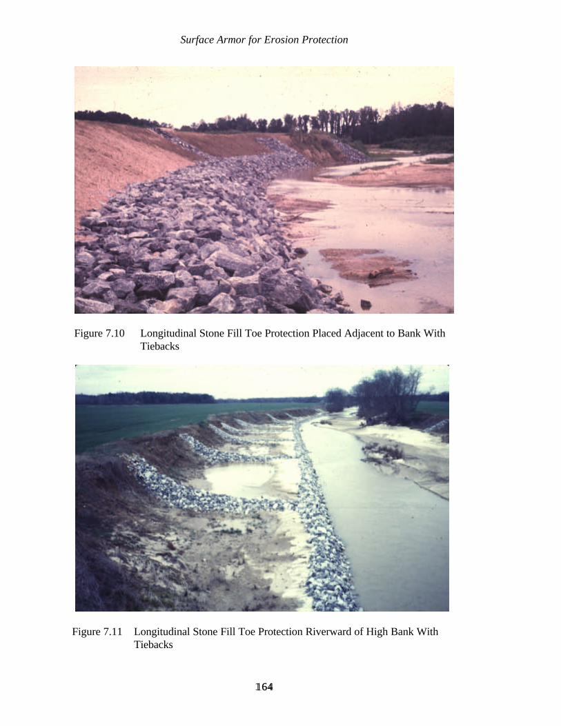
Surface Armor for Erosion Protection
164164
Figure 7.11 Longitudinal Stone Fill Toe Protection Riverward of High Bank WithTiebacks
Figure 7.10 Longitudinal Stone Fill Toe Protection Placed Adjacent to Bank WithTiebacks

Surface Armor for Erosion Protection
165165
Rubble from demolition of pavement or other source;Slag from steel furnaces; andAutomobile bodies.
7.2.1 CONCRETE BLOCKS
7.2.1.1 Description
The discussion here will focus on armor revetments composed of blocks which areplaced as individual components. Additional discussion of concrete blocks fastened togetherin flexible mattresses is provided in 7.4.1.
A wide variety of block shapes and placement techniques can be used. Some haveevolved from engineering analyses, some from observation and empiricism, and some fromimprovisation using readily available materials.
Blocks designed specifically for bank armor are commercially available. Forms forcasting concrete blocks locally are often available from distributors, and may be aneconomical alternative to purchasing and transporting precast blocks.
7.2.1.2 Advantages
Concrete blocks are durable, provide permeability for bank drainage, and are amenableto complementary vegetative treatment. Most designs provide easy pedestrian access towater's edge, and may be more aesthetic than other materials. Channel boundary roughnessis less than with many other techniques. Hand-laid blocks will fit irregularly shaped areas, anddo not demand access by heavy construction equipment.
7.2.1.3 Disadvantages
A fabric or granular underlayment (“filter”) is often required. Successful performanceof the underlayment is more critical than with a riprap armor. In areas of high turbulence orwaves, displacement of one block can lead to successive displacement of adjacent blocks.
If blocks are cast on-site, delays from inclement weather may be a problem.
At sites that are subject to theft or vandalism, blocks of an attractive size and shapemay suffer serious attrition.

Surface Armor for Erosion Protection
166166
7.2.1.4 Typical Applications
In addition to typical application as bank armor, blocks can be used effectively forspecial features such as ditch and spillway linings, culvert outlets, walkways. They aresuitable for areas to be vegetated which are subject to erosive forces which vegetation alonecould not withstand.
Manufactured blocks are sometimes the least-cost alternative for self-adjusting armor. This is usually in regions where riprap must be transported long distances at great expense,or at sites of high erosive forces where a thick armor of riprap can be replaced by a thinnerarmor of concrete blocks.
They are well-suited for projects where labor-intensive hand placement is acceptable.Efficient mechanized placement is an option when the blocks are fabricated into mattresses.
7.2.1.5 Design Considerations
Manufacturers' recommendations and/or guidance from laboratory tests and fieldexperience, should be followed in determining block thickness and other details.
7.2.2 SACKS
7.2.2.1 Description
Sacks as an armor material can be considered to be artificial “rocks” of uniform sizeand shape. The sacks may be made of paper, burlap, or a synthetic material. The fill materialmay be soil or aggregate of various types, with or without cement.
7.2.2.2 Advantages
Sacks can be placed on a steeper slope than stone.
Materials are often available locally. The hydraulic roughness is low, and they forma walkable surface. The “cobblestone” effect may be more aesthetic than some othermaterials.
7.2.2.3 Disadvantages
A sack armor may tend to act monolithically on steeper slopes, therefore small failurescan lead to large ones. The characteristic of being “stackable” may lead to their use on slopes
Surface Armor for Erosion Protection
167167
too steep for long-term geotechnical stability, although this is a flaw in design rather than aninherent flaw of sacks themselves.
Synthetic bags, which are sometimes marketed as being suitable for filling with soilor sand rather than a cementious mixture, may be vulnerable to environmental hazards suchas fire, ice, vandalism, livestock traffic, floating debris, and rupturing by the roots ofvegetation.
A fabric and/or granular underlayment (“filter”) is usually required, whereas that maynot be the case with a riprap blanket. Successful performance of the underlayment is morecritical than with riprap.
A sack armor may not be as likely to support vegetative growth as readily as someother armor materials, especially if a cementious filler is used, or if the sacks are placed ona steep slope. However, in situations where vegetative growth is not desirable, this wouldbe an advantage.
7.2.2.4 Typical Applications
Sacks are especially suitable for use on transitions to steep slopes, or in areas wherethey are aesthetically desirable. If low-cost labor is available, they may be the most cost-effective method, especially on small projects.
7.2.2.5 Design Considerations
If commercial bags are used, then the manufacturer's guidance should be followed.Otherwise, the following guidance should be used:
Sack material selection is not critical if the sacks are to be filled with a cementiousmixture, as long as they are strong enough to withstand the stress of handling, and will notdegrade before the cement sets up. The choice of sack material can then be based oneconomics, considering the total operation of filling, closing and placing. Some commercialbags have ingenious provisions to speed filling and closing, thus reducing labor costs.Prefilled bags are available in some areas. An alternative to specifying a particular sack forwork to be contracted out is to allow bidders a choice of sacks, within broad guidelines.
Sack size should be small enough for laborers to handle. General purpose sacks suchas burlap bags or sandbags should have a capacity larger than the desired in-place volume, sothat the open end can be folded under the bag as it is placed.
The usual filler material is a sand/cement mixture. Since labor costs are highregardless of fill material, use of a non-cementious filler should be considered only ifsignificant savings would result, and a long life is not required. One such case would be for
Surface Armor for Erosion Protection
168168
slopes where vegetation will be established for permanent protection, and permanent toeprotection is provided by some other material. Otherwise, a cementious filler is recommended.A common mix is 5 parts aggregate to 1 part cement by volume. Ideal aggregatecharacteristics are discussed in 7.2.3, but streambed sands are usually suitable.
A typical sack revetment is shown in Figure 7.12. Placing the bags flat on the bankslope is recommended only if the slope is flatter than 1V on 2.5H. The practice on steeperslopes is to provide an overlap, which adds to structural stability as well as allowing someadjustment to scour and settlement without exposing bare bank. On slopes of 1V on 2.5Hor 1V on 2H, the bags should be overlapped by placing with the long dimension pointingtoward the bank, while on slopes steeper than 1V on 2H, the bags should be overlapped withthe short dimension pointed toward the bank. This produces the most efficient bank coveragewhile still providing the desired overlap between bags. The bags should be placed withstaggered vertical joints, as in laying bricks.
Filling of bags is usually done with a portable concrete mixer when a soil-cement mixis used. For maximum convenience in handling, the bags can be filled with dry material ratherthan adding water during the mixing process. After placement, the bags can be sprinkledwith water to speed hydration. Ambient moisture, rainfall, and/or stream flow will completethe hydration process.
There are two alternative approaches to bonding between adjacent sacks. “Nobonding” permits individual sacks to adjust to scour and settlement, whereas “bonding”provides greater overall structural strength. The designer must decide which is preferred fora particular application. Generally, bonding is desirable only if design velocity is so high thatindividual bags might be displaced. Otherwise, adjustability is desirable. Bonding can bediscouraged by using tightly woven sacks or placing heavy paper between adjacent courses.Bonding can be encouraged by using porous sacks, placing cement between cold courses, ordriving rods through adjacent bags.
7.2.3 SOIL-CEMENT BLOCKS
7.2.3.1 Description
Soil is mixed well with sufficient cement to provide a durable bond between soilparticles. The resulting monolith is broken into blocks of various sizes, which are used toarmor the bank.

Surface Armor for Erosion Protection
169169
Figure 7.12 Typical Sack Revetment
Surface Armor for Erosion Protection
170170
7.2.3.2 Advantages
Besides the general characteristics of adjustability to bank irregularities and self-healing properties, soil-cement blocks allow the utilization of locally available materials.
7.2.3.3 Disadvantages
Soil-cement blocks have a lower specific weight than riprap, and obtaining acceptablegradation and durability are highly dependent on closely controlled construction operations.Construction operations are adversely affected by wet or cold weather.
7.2.3.4 Typical Application
Soil-cement blocks are most often used when stone is prohibitively expensive, suitablesoil for aggregate is available at or near the job site, and personnel experienced in making theblocks are available. Cost savings over alternative methods are more likely on larger projectswhich amortize the cost of operations set-up.
7.2.3.5 Design Considerations
Since soil-cement blocks are simply man-made rocks, the general principles ofeffective riprap design apply. However, the lower specific weight of soil-cement requireslarger block sizes for equivalent protection, and size criteria as precise as those for riprap donot exist.
For other aspects of design, extensive research and field experience has resulted indetailed recommendations by the Portland Cement Concrete Association and others. Thefollowing points are especially important:
Specifying a suitable soil as aggregate is critical. Although soil-cement can bemade from almost any soil, soil with at least 55 percent sand and no more than35 percent fines is recommended. A “graded” soil of mostly sand, but withsome non-clayey fines and gravel provides the optimum combination ofworkability, strength, durability, and minimum cement requirements.
Blocks with a low cement content may be vulnerable to damage from waves,impingement by high velocity streamflow, and abrasion from transportedsediment.
A controlled gradation of finished blocks is best obtained by spreading mixedsoil-cement in slabs of varying thicknesses, then scarifying the upper portionof each slab early in the curing process. Following curing, the slabs can be
Surface Armor for Erosion Protection
171171
broken into blocks by driving heavy equipment over them. Sizes of thebroken blocks will vary according to the thickness of the slabs and thedistance between scarification lines.
Careful quality control during construction is vital to insure thatspecifications are met.
7.2.4 RUBBLE FROM DEMOLITION
7.2.4.1 Description
The ideal rubble for erosion protection is a dense, durable material such as concreteor asphalt with a size gradation similar to riprap.
7.2.4.2 Advantages
Rubble is economical, and recycles material that otherwise might be wasted.
7.2.4.3 Disadvantages
Even dedicated advocates of economy and recycling are likely to view rubble on astream as unesthetic at best. Leachates from some rubble may pose a water quality problem.
Since rubble is usually available only on a “take it or leave it” basis, it may be toosmall and/or too large. Losses of finer material due to piping, overbank drainage, andstreamflow is likely. Conversely, larger rubble precludes attaining a uniform and efficientlayer thickness.
7.2.4.4 Typical Applications
Rubble would be considered where the justification for a more sophisticated butexpensive armor does not exist, suitable rubble is available, and the environmentalshortcomings are acceptable. It is often used in windrow form.
7.2.4.5 Design Considerations
Although precise control is likely to be impossible, the same general principles as forriprap will apply to weight, gradation, and durability requirements for rubble. The layerthickness should be equal to at least 1.5 times the maximum block size, although controlling

Surface Armor for Erosion Protection
172172
the placement of larger blocks may not be practical, and their in-place orientation may dependmore on chance than on design specifications.
When rubble contains large amounts of fines and/or oversize blocks, the layerthickness should be increased generously over the theoretical riprap thickness that would berequired for the same site conditions.
A granular or fabric filter can be used to improve performance, but at the sacrifice ofeconomy. Some risk in performance is inherent in rubble, and the additional risk of using itwithout a filter is usually accepted.
7.2.5 SLAG FROM STEEL FURNACES
7.2.5.1 Description
Slag is a granular material which is a by-product of steel-making. It is mostcommonly known for its use as railroad track ballast.
7.2.5.2 Advantages
Slag may be relatively inexpensive when available locally, and its use recycles materialthat might otherwise be wasted. It is dense, durable, and angular, and is often available in arange of sizes, which gives it the same basic properties as stone riprap.
7.2.5.3 Disadvantages
Leachates from slag may affect water quality, and some displacement of slag bypersons searching for scrap steel has been reported. At one site on the Ohio River, somespalling from weathering and subsequent erosion of the fines has been observed, but this hasnot occurred at other sites.
7.2.5.4 Typical Applications
Slag would be a suitable choice where it is the least costly effective armor material,and where site conditions and chemical tests of the slag indicate that there would be nodetrimental effects on water quality.
Surface Armor for Erosion Protection
173173
7.2.5.5 Design Considerations
Principles of design are the same as for stone riprap. Slag from oxygen or electricfurnaces is denser than that from blast furnaces, and may even be denser than stone.Therefore, the riprap design criteria in Appendix A would be applicable. The designer mayhave a choice of different gradations if slag is commonly used locally for construction. Thesize gradation is sometimes enhanced by the addition of scrap refractory brick.
Slag has been used both with and without an underlayment. On the Ohio River, an18 inch blanket without underlayment was as successful as a 12 inch blanket on top ofengineering fabric.
7.2.6 AUTOMOBILE BODIES
Automobile bodies are included is this listing only because they have been usedoccasionally for erosion protection. No redeeming features beyond low cost can be claimed.Environmental considerations make their use as streambank protection objectionable.
7.3 RIGID ARMOR
The following paragraphs outline the general description, advantages, disadvantages,typical applications, and design considerations for most rigid armor used as a bankstabilization method:
Rigid armor is an erosion-resistant material which has little or no flexibility toconform to bank irregularities occurring after construction. Typically, thearmor is placed directly on the bank slope in a fluid or chemically reactivestate, then hardens.
The most common rigid armors are:
Asphalt;Concrete;Grouted riprap (or other grouted armor material); and Soil-cement.
Materials which have a more restricted use, but which can be classified asrigid armors, are chemical soil stabilizers, and clay.
Advantages, disadvantages, typical applications, and design considerations forrigid armor are discussed collectively, followed by a discussion of distinctivecharacteristics of each type and sources for additional information on eachtype.
Surface Armor for Erosion Protection
174174
Advantages are: The most common rigid armors will withstand highvelocities, have low hydraulic roughness, and prevent infiltration of water intothe channel bank. They are practically immune to vandalism, damage fromdebris, corrosion, and many other destructive agents. The most common rigidarmors are easily traversed by pedestrians.
Disadvantages are: A rigid armor requires careful design and quality controlduring construction, and unfavorable weather conditions can causeconstruction delays. Chemical soil stabilization, clay, and ice have a limitedrange of effectiveness.
Provision for draining groundwater and preventing the buildup of excesspositive pore water pressures, in the form of a filter or subsurface drains, mustusually be provided for impermeable armors, which may significantly increasethe cost of the project.
Most rigid armors are difficult or impossible to construct underwater,although this difficulty can be alleviated for concrete by using one of thecommercially available fabric mattresses (see “Concrete” below). Asphalt hasbeen placed underwater in some cases (see “Asphalt” below).
Rigid armor, being inflexible, is susceptible to breaching if the bank materialsubsides or heaves. Increased wave runup on a smooth rigid armor may bea concern for some projects.
Some of these materials have little to recommend them environmentally, beingbiologically sterile and perhaps unacceptable aesthetically, depending on thesurroundings.
Typical applications are: Rigid armor in the form of concrete, asphalt, orgrouted riprap is often considered for use in situations where high velocitiesor extreme turbulence make adjustable armor ineffective or very expensive.Typical uses are in conjunction with hydraulic structures or in artificialchannels on steep slopes.
Rigid armor may be the preferred alternative in flood control or drainagechannels where low boundary roughness is mandatory, or in water supplychannels where prevention of water loss due to infiltration into the bank isimportant. It is suitable for bank slopes which must be easily traversed bypedestrians or recreational users, if the slope is not too steep for safety.
Rigid armor is sometimes the least costly alternative, typically whereadjustable armor is not available locally, especially if a geotechnical analysisof the bank material indicates that elaborate subsurface drainage work is notnecessary.

Surface Armor for Erosion Protection
175175
Design considerations are: Careful attention to geotechnical stability of thebank, provision for overbank and internal bank drainage, and toe protectionis especially critical for rigid armor. Flexible or self-launching toe protectionis appropriate in many cases, such as in larger channels where dewateringduring construction is impractical and significant toe scour during high flowsis expected.
7.3.1 ASPHALT
Asphalt is available in three forms: Pure asphalt, which can be mixed with soil orother aggregate and spread on the bank; cutback asphalt, which is pure asphalt mixed withsolvent; and asphalt emulsion, which is pure asphalt mixed with water and an emulsifyingagent. The generic term “asphalt” applied to bank stabilization usually infers pure asphalt.The other two types can be used in the same manner as chemical soil stabilizers; that is, bybeing sprayed directly onto the bank and allowed to penetrate the soil before hardening intoa cohesive mass. The properties of an emulsion can be varied by using various emulsifyingagents.
Asphalt mixes with a high sand content are sometimes used to retain somepermeability to relieve hydrostatic pressure. However, these mixes have been reported tobecome more brittle and less permeable upon long exposure to the elements, and weatheringmay result in a slow loss of thickness.
The use of asphalt placed underwater on the Lower Mississippi River wasdiscontinued because of problems with placement control and inconsistent performance, andas a result of the development of an efficient and effective articulated concrete mattress.However, it should be noted that the Lower Mississippi River presents extremely difficultconstruction conditions, with high velocities, great depths, and steep underwater slopes.
7.3.2 CONCRETE
On slopes above water, concrete can be placed in the conventional manner with forms,or can be pumped into fabric mattresses which serve as forms for a fine aggregate concrete.Prefabricated slabs may be the least costly alternative for some sites. An armor of relativelysmall slabs would assume some of the characteristics of concrete block armor (see 7.2.1).
Fabric mattresses are the preferred method for underwater placement, and areavailable in various configurations. The appropriate design for a given application will dependon the need for relief of hydrostatic pressure, the design velocity, and the preferred roughnesscharacteristics. Some mattresses are described as being flexible by the manufacturer, althoughthis description should be objectively examined by the project engineer if flexibility is a criticalfactor for a specific project. Section 7.4.2 below provides further discussion under “FabricMattresses.”
Surface Armor for Erosion Protection
176176
7.3.3 GROUTED ARMOR
Grouting of an armor layer with asphalt or concrete enables the armor to withstandhigher flow velocities, provides a smooth surface for pedestrian or vehicle access, and reducesthe hydraulic roughness of the armor. Grouting is also sometimes used with gabion armorsor structures to increase the resistance of the gabions to corrosion and abrasion.
Grouting allows the use of locally available stone or cobbles which are not largeenough to withstand design flow velocity if used alone. A grouted armor of streambedcobbles with the surface of the cobbles exposed is more aesthetically pleasing than most otherarmor materials.
When applied to a riprap armor, grout which thoroughly penetrates the riprap enablesa smaller stone size and thinner layer to be used for a given velocity of flow. If grouting isused only to reduce hydraulic roughness or to improve trafficability, thorough penetration ofthe armor layer is not necessary. However, in that case, stone size and layer thickness shouldbe designed as if the grout were not present.
7.3.4 SOIL-CEMENT
Soil-cement will withstand relatively high velocities and is usually less expensive thanconcrete, asphalt, and grouted riprap. It is more durable than chemical stabilization, clay, andcertainly ice, but usually somewhat less durable than concrete, asphalt, and grouted riprap,assuming that sound design and construction procedures are followed for all. A typical soil-cement application is shown in Figure 7.13.
General factors affecting the use of soil cement were discussed under soil-cementblocks in Section 7.2.3. Its use as a rigid armor is usually an economic decision. However,an additional consideration is that, when mixed in a batch plant rather than mixed in-place onthe bank slope, it can be placed as a rigid armor in stair-step fashion. This allows it to be usedon steep slopes where permitted by geotechnical considerations, and provides the capabilityto construct an armor of great thickness if required to resist high flow velocities, abrasivesediment transport, and wave attack. Use of a batch plant has the further advantage ofproviding consistent quality control.
In-place mixing is an alternative if a relatively flat bank slope is provided. However,the thickness of the armor is then limited by the mixing capability of the mixing vehicle, andquality control is not as assured.

Surface Armor for Erosion Protection
177177
Figure 7.13 Typical Soil Cement Application
Surface Armor for Erosion Protection
178178
7.3.5 CHEMICAL SOIL STABILIZATION
A number of commercially available products, including lime, can be used to increasecohesion of soil particles or to provide a hard film at the soil surface. Under favorableconditions, even those products which eventually break down upon exposure to the elementsmay be effective in providing erosion protection until vegetation becomes established.
Because specific site conditions can greatly affect performance, the feasibility of thisapproach and appropriate design guidance for a particular project can be determined only byobtaining evidence of satisfactory performance under similar conditions from previous usersor from the manufacturers.
7.3.6 CLAY BLANKET
When the upper slopes of a bank are exposed to small erosive forces, but the existingsoil has insufficient cohesion to resist them, it may be effective, environmentally beneficial,and economical to utilize a clay blanket instead of a structural armor. The cohesive propertiesof the clay provide resistance to erosion, and its moisture holding properties may enhancevegetative growth. This approach would be prudent only on projects where the consequencesof failure in the event of unfavorable streamflow or weather conditions are low, or whereadequate monitoring, and reinforcement if required, are assured.
7.4 FLEXIBLE MATTRESSES
The following paragraphs outline the general description, advantages, disadvantages,typical applications, and design considerations for most flexible mattresses used as a bankstabilization method:
The basic concept of a flexible mattress is that material or objects whichcannot resist erosive forces separately can be fastened together or placed ina flexible container to provide adequate resistance to erosive forces, whilepartially retaining the desirable characteristics of adjustable armor, especiallythat of flexibility.
The most common flexible mattress materials are:Concrete blocks;Fabric; andGabions.
Materials which have a more limited use are:Grids (for confining earth or other fill material);Used tires; andWood.
Surface Armor for Erosion Protection
179179
Advantages are: Flexibility to adjust to scour or settlement and still remainin contact with the bed and bank is the most obvious shared trait. Mostmattress materials which are sold under trade names share another advantage- they are available in various configurations, thus can be applied to a varietyof situations.
Flexible mattresses can be placed underwater with a relatively high degree ofconfidence. If properly anchored to a geotechnically stable bank, they can beplaced on steep slopes.
They can be walked upon easily, thus are suitable for slopes used bypedestrians.
Disadvantages are: Mattress components are subject to deterioration from theelements and vandalism. However, the damage is often within acceptablelimits, and, since the various types are affected differently, identification of thehazards enables the designer to select an appropriate mattress for a givenapplication. The construction of some types of mattress is labor intensive, andmay require skills not commonly available. However, the labor intensiveaspect may not be a disadvantage in all cases, and may be an advantage insome cases.
Typical applications are: This compromise between adjustable armor andrigid armor is most attractive when economical materials can be used for themattress. In fact, the origin of some variations can be traced directly tocreative use of local materials where no protective material of local origin wasadequate to withstand the erosive forces in a given application, and where themost suitable method was the one which required the least amount of costlyimported material, a requirement which is often met by a flexible mattress.
Some types of mattress are suitable for use where erosive forces are so severe,or construction operations are made so difficult by great depth and/or highvelocity of flow, that other types of armor are not effective or cannot beplaced reliably. An example is the articulated concrete mattress developed bythe U.S. Army Corps of Engineers for the Lower Mississippi River over thelast 60 years. The ACM has evolved into a highly efficient product placed byspecialized floating equipment adapted to operation under severe conditionsof velocity and depths.
Some types of mattress are suitable for use in areas which are to be used bypedestrian or vehicular traffic.
Design considerations are: Beyond the general considerations discussedbelow for the various types of mattresses, the manufacturers of commercialmattresses have developed very detailed design guidance for their products.
Surface Armor for Erosion Protection
180180
7.4.1 CONCRETE BLOCK MATTRESS
The advantages, disadvantages, and typical applications of concrete blocks as armorwere discussed in Section 7.2.1. Some additional considerations which apply to the use ofconcrete blocks in mattress form are as follows:
Mattresses provide a higher degree of safety from progressive failure of thearmor due to displacement of individual blocks from hydraulic or geotechnicalforces or vandalism.
Placing of mattresses is more mechanized and less labor intensive than placingindividual blocks.
Some commercial mattresses incorporate an engineering fabric, which willeliminate the need for a separate filter layer under some conditions.
Precast concrete blocks can be formed into a flexible mattress in several ways: byfastening them to engineering fabric, by fastening them together with cable or synthetic rope,or by forming them in ingenious shapes which are then interlocked. All of these varieties arecommercially available.
7.4.1.1 Design Considerations
Concrete block mattress will usually withstand hydraulic forces greater than an equalthickness of riprap. However, all designs are not equal, and manufacturers being consideredas a source for a specific project should be asked to furnish evidence of adequacy.
The most conservative design approach, which would be especially appropriate forareas of high turbulence and areas where waves create the critical loading, is to ignore anyextra uplift resistance which is provided by the blocks being attached together. This extraresistance would be assumed to be a safety factor, rather than being taken into account whenselecting a block size for hydraulic loading. The rationale is that the “pumping” actioncreated by even a small amount of uplift of the blocks might result in loss of bank material orfailure of the mattress connections or bonding system.
Anchoring the mats to the bank slope is usually recommended. This should not beconsidered as adding to the geotechnical stability of the bank, but rather as providing a marginof safety from mat displacement if small slope movements occur.
Surface Armor for Erosion Protection
181181
7.4.2 FABRIC MATTRESS
7.4.2.1 Description
Fabric mattresses made of synthetic material and filled with concrete grout, othercohesive mixtures, or sand are available from various manufacturers. Tubular-shaped bagsare also available; these can be filled and placed either parallel to the streambank as abulkhead or perpendicular to the streambank as a dike, or can be used to fill scour holes orundermined slopes.
7.4.2.2 Advantages
A fabric mattress is relatively easy to place, and fill material is often available locally.Some designs have a low hydraulic roughness.
7.4.2.3 Disadvantages
Some designs provide only limited permeability and flexibility to conform toirregularities in the bank.
7.4.2.4 Design Considerations
Many different designs are available. This allows the designer to discuss particularsite conditions with manufacturer's representatives in order to select a mattress whichemphasizes particular requirements, i.e., stability under hydraulic forces, filter andpermeability properties, flexibility, hydraulic roughness, resistance to deterioration, orcompatibility with vegetation. One form, intended primarily for filling with concrete,integrates cables into the mattress to provide flexibility without separation even if the bagdeteriorates.
Potential subsurface drainage problems must be identified, and the installationdesigned and monitored accordingly.
Use of a non-permanent fabric and fill material may be acceptable on the upper bankif vegetation for permanent protection is planned. This approach has also been used on lowerbanks and bed where the fabric is permanently underwater, and not subject to atmosphericdeterioration, vandalism, or impact from debris or vessels. Obviously some degree ofuncertainty exists when using perishable materials, so site conditions, expected project life,and the consequences of failure must be carefully evaluated.
Polyester fabric has been reported to be subject to deterioration from the high pH ofconcrete curing.
Anchoring the mattress to the bank slope is usually recommended by manufacturers.
Surface Armor for Erosion Protection
182182
7.4.3 GABION MATTRESS
7.4.3.1 Description
A gabion mattress consists of a mesh container filled with cobbles or quarried stone.Several firms market the containers and furnish technical assistance. Specialized equipmentor accessories are sometimes used on large jobs for efficiency, or on jobs requiringunderwater placement.
A form of gabion which is a hybrid between flexible mattress and adjustable armor isthe “sack” or “sausage,” which can be filled faster than mattress or box shapes, making itsuitable for use in emergency situations. However, it makes less efficient use of material, andis less common than traditional mattress or boxes.
7.4.3.2 Advantages
Since relatively small stones are used to fill gabion mattresses, a filter underlaymentis often not required. The hydraulic roughness is fairly low, especially if the gabions arecarefully filled or grouted. The appearance is more natural than some other materials, andgabions are conducive to vegetative growth.
A gabion mattress is often used in conjunction with gabion dikes or retaining walls,since the same construction practices can be used. A gabion mattress can be tailored toirregular shapes in transitions from one type of protection to another, or around drains andother structural features.
7.4.3.3 Disadvantages
A gabion mattress is less flexible than some concrete block mattresses. The mesh isnot immune to deterioration from the elements, although corrosion-resistant coatings orgrouting can be used to significantly alleviate potential problems of deterioration.
7.4.3.4 Design Considerations
Manufacturers have developed detailed guidance for every feasible application, andthis guidance should be obtained early in the planning process. Some general factors toconsider in design are discussed in the following paragraphs.
For given hydraulic conditions, a gabion mattress can be substantially thinner than ariprap blanket. Recent model tests, as reported by Simons et al. (1984) provide guidance formattress thickness related to shear stress and velocity. Two conditions were analyzed:

Surface Armor for Erosion Protection
183183
Initial movement of stones within the mattress; and
A condition where the mattress shape has been deformed by stone movement,but the mattress is still functional.
The tests indicated that ungrouted mattress thicknesses of nine inches (23 centimeters)or less could withstand significantly higher velocities than previously believed. Groutingwould increase the allowable velocities even more. It was noted, however, that wire meshstrength may be a major factor controlling mattress stability.
Filler stone sizes must be more uniform than for typical riprap. The smallest size mustbe larger than the mesh openings, but the largest size must be small enough to eliminate largevoids between stones in the filled mattress. Streambed cobbles are sometimes used to reducecost where they are locally available.
Corrosion, abrasion, and vandalism can be minimized by grouting the gabions with asand-asphalt mastic or concrete. However, the accompanying loss of permeability mayrequire that special provision for hydrostatic pressure relief be provided. Also aesthetic andenvironmental aspects of the project may suffer.
For corrosive or abrasive situations, previous users or manufacturer's representativesshould be consulted for information on measures used to ensure successful application undersimilar conditions. Even in areas of good water quality, water chemistry may be such thatgalvanized wire will corrode. For this reason, a polyvinyl chloride coating on the wires isoften specified.
Care in handling and filling is necessary to avoid damage to protective coatings,especially with plastic coated gabions in cold weather. For work above water, filling in placeis preferable to filling before placing. Otherwise, extreme care must be taken during handlingto avoid deforming or damaging filled gabions.
Construction must be carefully supervised. Some crucial points, such as care duringfilling, and complete lacing of the mattress components, are costly to a contractor's operationand present a temptation for short cuts. Some handwork is usually necessary for properfilling, and this in particular may be resisted by a contractor unless it is clearly specified.
On steep slopes, keying-in or anchoring the mattress at the top of the slope isrecommended.
For large jobs, a manufacturer may offer custom-sized gabions for optimum designand construction efficiency.
Surface Armor for Erosion Protection
184184
7.4.4 GRID CONFINEMENT
7.4.4.1 Description
This approach uses a grid several inches thick, resembling a “honeycomb,” to confinesoil or other material on the bank slope. It provides a level of protection which is lessresistant to erosion than conventional armoring, but more resistant than unsupported soil,granular fill, or vegetation.
7.4.4.2 Advantages
By using locally available materials, grid confinement may offer a cost savings whereerosive forces are moderate. When filled with soil, it is highly compatible with vegetativetreatment.
Grid confinement also enhances the resistance of the slope to shallow failure. The gridcan also serve as a form for bituminous or similar armor material on steep slopes, in whichcase some beneficial increase in flexibility of the armor can be expected, since the gridmaterial acts as joints in the armor.
7.4.4.3 Disadvantages
When filled with a non-cohesive material, grid confinement will not withstand as highvelocities as some other flexible mattresses. When filled with asphalt or concrete, it assumesto some extent the unfavorable characteristics of rigid armor discussed in 7.3.
7.4.4.4 Design Considerations
Some manufacturers have developed guidance for allowable velocities and otherhydraulic factors, and can furnish specific recommendations for particular applications basedon laboratory tests and field experience.
The manufacturer may recommend a geotextile underlayment, and, if the grid is filledwith a non-porous material, filter points to allow drainage should be incorporated into thedesign.
The grid should be anchored to the bank slope according to the manufacturer'srecommendation.
Surface Armor for Erosion Protection
185185
7.4.5 USED-TIRE MATTRESS
7.4.5.1 Description
Used-tire mattress consists of tires fastened together with bands, cable or rope.Whole tires are normally used, but tires sliced in half or tires with pieces removed aresometimes available.
7.4.5.2 Advantages
Tires are often available at low cost, and use of tires in erosion control may be moreenvironmentally sound than landfill disposal. A tire mattress is conducive to the establishmentof woody vegetation.
7.4.5.3 Disadvantages
No formal guidance is available for determining limits of hydraulic forces. A tiremattress is not suitable for severe conditions unless an underlayment and multiple layers oftires are used, which negates the cost advantage. Vulnerability to hydraulic forces, vandalism,and theft is greatest immediately after construction, before exposed areas become vegetated.
Environmental regulations may prohibit the use of tires in many areas. Also, a tiremattress is not aesthetic, although if site conditions permit heavy vegetative growth anddeposition of sediment, the appearance improves with time.
7.4.5.4 Design Considerations
To combat vandalism and theft, and to reduce buoyancy during high flows, if wholetires are used, then one or more of the following measures should be employed:
Stout and durable synthetic or galvanized connections;
Backfilling with earth over the completed revetment; and
Cutting or burning a hole in the upper sidewall of each tire.
Less durable connections can be used if the quick establishment of woody vegetationis certain, and vandalism is not expected to be a problem. However, the savings in cost arenot likely to be significant.
The mattress should be anchored on the slope with screw anchors, driven anchors, orburied anchors. If little toe scour is expected, and the outer edge of the mattress is not placed

Surface Armor for Erosion Protection
186186
underwater, the outer edge can be anchored in the same manner as the slope. An alternativefor little toe scour and moderate velocities is to fill the outer few rows of tires with concrete.A more conservative approach is to use one of the toe protection methods discussed in 6.3.
Tire diameters should not be allowed to vary greatly, otherwise it will be difficult tomake good connections consistently. A simple way to minimize this difficulty is to specifythat only standard tires of nominal 13-inch to 16-inch wheel diameter be used.
7.4.6 WOODEN MATTRESS
7.4.6.1 Description
Wooden mattress is one of the oldest techniques of bank stabilization, even thoughit is seldom used now in developed regions. The mats may be made of poles, brush, orlumber. The material can be fastened together by weaving, binding, cabling, clamping, orspiking. The mattresses are sunk by ballasting with stone or other heavy materials. Sometypes of mat may be so buoyant that the ballast is a significant component of the protection,as well as a large part of the cost.
On navigable rivers during periods when current speed is slow enough that the matscan be safely maneuvered in tow, mats with sufficient buoyancy can be assembled near thematerials supply point or near a source of labor, then towed to the project site. Individualtows of as much as 150,000 square feet of mat were reported on the lower Mississippi River.
At least one marine construction firm has adapted modern technology to theconstruction of wooden mattress, while still retaining traditional skills for use whereappropriate. They have also extended new technology to the point of developing syntheticmaterials for use in mattresses, in order to overcome some of the inherent problems of wood.
7.4.6.2 Advantages
Wood is usually available locally, and is a renewable resource. If inexpensive laboris available, a wooden mattress may be the least cost alternative. Wood is relatively durablewhen permanently submerged in freshwater.
7.4.6.3 Disadvantages
Near-site availability of material is usually required for wooden mat to be competitivewith other methods. Assembling and placing the mattresses are labor-intensive operations.Design and construction is surprisingly complex, requiring skills which have become rarer asother methods have become more popular.
Surface Armor for Erosion Protection
187187
In most climates wood will deteriorate quickly if exposed to alternate wetting anddrying. Therefore, it is not a suitable material for use above low water unless treated lumberis used (which may affect water quality), or unless frequent maintenance or the establishmentof vegetation is planned.
The durability of metallic components may be poor underwater. This is a significantshortcoming, since the mat must remain intact to function properly.
Construction is difficult if currents are swift, depths are great, or the flow carries largeamounts of floating debris.
The designs that use lumber or long poles woven into a mat are stiff, which limits theircapacity to conform to bank and bed irregularities. Severe erosive forces require thick mats,which reduces flexibility in proportion to thickness, and loss of permeability greatly increasesthe difficulty in sinking in swift currents. In fact, the stiffness of sturdy woven pole andlumber mats led to them being replaced on the lower Mississippi River about 1900 by willowfascines, or bundles, cabled together into mats. The fascine mat was more flexible. However,the high labor cost and diminishing willow supply, as well as sometimes ineffectualperformance, led to the fascine mat being replaced in turn about 60 years ago by the muchmore successful articulated concrete mat.
7.4.6.4 Design Considerations
The major causes of failure of wooden mattresses on the lower Mississippi River, asdiscussed by Elliott (1932). The disadvantages of this technique listed above provide a basisfor defining the most critical elements of design. The most serious shortcomings were foundto be:
Rotting of the mattress where it was alternately wet and dry;
Inability of the mattress to adjust to scour at its toe (riverward edge); and
Failure of fasteners and connecting components from corrosion, abrasion, orfatigue.
Design of a wooden mattress should address these points of vulnerability by utilizingthe following measures:
A secure, durable interface between the wooden mattress and whatever moredurable material is to be used to armor the upper bank should be specified.Since this interface will likely be underwater at the time of construction,unless the work is done at extremely low river stages, a material which issuitable for reliable placement underwater is dictated. Stone is an excellentchoice, although many other adjustable armors or flexible mattress materials

Surface Armor for Erosion Protection
188188
would also be suitable. Simplicity and economy of construction will beenhanced if the same material is used for the connection as for the rest of theupper bank. An overlap should be provided to ensure that any downslopemovement of the wooden mattress after placement will not result in anunprotected area of bank.
If significant toe scour is expected, then a wooden mattress should besupplemented by separate toe protection measures.
Fasteners and connectors should be of materials which are resistant tocorrosion, abrasion, and failure from fatigue due to flexing of the mattresswhen subjected to hydraulic forces. Synthetic materials, stainless steel, orheavily coated metallic components are therefore advisable.
Other major considerations for design are:
An overlap should be provided between adjacent mattresses in order tocompensate for uncertainties in underwater placement and future differentialdisplacement of the mattresses by hydraulic or geotechnical forces. As anexample, individual wooden mattresses on the lower Mississippi River wereoverlapped from a minimum of 5 feet to a maximum of 15 feet with theadjacent mats. The individual mats were laid from downstream progressingupstream so that the downstream edge of each mat lay over the upstream edgeof the adjacent mat, so that the upstream edges were not exposed to the flow.
Because wooden mattresses are relatively inflexible, and because shaping themto irregularities in the bankline is difficult, protruding points and otherirregularities should be removed or smoothed as much as possible during bankpreparation operations, and sunken debris that would interfere with themattress making contact with the underwater slope should be removed. Thisrequirement presents a dichotomy which is a major obstacle to the use ofwooden mattress, since the fact that wooden mattress is durable only whenpermanently submerged restricts its use to the subaqueous bank, whereremoval of bankline irregularities and debris is most difficult, and in fact islikely to be impractical at depths greater than ten feet with standardconstruction equipment, even if barge mounted.
189189
CHAPTER 8
INDIRECT TECHNIQUES FOR EROSION PROTECTION
As in the previous chapter, descriptive information for most techniques presented inthis chapter is generally followed by a discussion of advantages, disadvantages, typicalapplications, and design considerations as appropriate. In order to minimize redundancy,these topics are discussed at the broadest possible level in the hierarchy of the text; in otherwords, aspects which are shared by all techniques are discussed at the beginning of thechapter; aspects which are shared by a group of techniques are discussed at the group level;aspects that are peculiar to a smaller category of techniques, or to a single technique, arediscussed at the appropriate level of specificity.
The extent of the discussion of specific techniques ranges from detailed designguidance to a brief description for some specialized techniques. Therefore, a completeunderstanding of a specific technique requires perusal of all material at a broader level in thetext, as well as material peculiar to that technique.
The following paragraphs outline the general description, advantages, anddisadvantages for most indirect techniques used in bank stabilization methods:
Indirect protection structures extend into the stream channel, and redirect theflow so that hydraulic forces at the channel boundary are reduced to anon-erosive level. Indirect protection techniques can be classified as follows:
Dikes and RetardsDikes
Permeable dikesImpermeable dikes
RetardsPermeable retardsImpermeable retards
Other Flow DeflectorsBendway weirsIowa vanes
Indirect Techniques for Erosion Protection
190190
Advantages are: Little or no bank preparation is involved for indirectprotection. This reduces costs and riparian environmental impacts, simplifiesthe acquisition of rights-of-way, eliminates material disposal problems, andusually allows existing overbank drainage patterns to remain undisturbed.
Existing channel alignment and/or geometry can be modified, although thechanges may not always be beneficial or predictable.
Indirect approaches usually increase geotechnical bank stability by inducingsediment deposition at the bank toe, although this process may not be rapidor reliable enough to meet project goals.
Disadvantages are: Where geotechnical bank instability or erosion fromoverbank drainage is a major factor, the fact that indirect protection does notimmediately relieve these problems can be a serious and often unacceptableshortcoming.
Because significant changes in flow alignment, channel geometry, roughness,and other hydraulic factors often result from indirect protection structures,special attention must be given to the stream's morphological response.
Some types of indirect protection structures may be a safety hazard if thestream is used for recreation or navigation, and the aesthetics of some typesoften leave much to be desired, although vegetative growth may ultimatelyreduce the visual impact in most regions.
Since indirect methods extend into the stream channel, their construction maybe difficult, especially during high flow. Also, the structures may be subjectedto severe hydraulic conditions throughout their lifespan, and should be closelymonitored to insure that maintenance is performed as necessary.
8.1 DIKES AND RETARDS
The following paragraphs outline the general description, advantages, disadvantages,typical applications, and design considerations for dikes and retards used in bankstabilization methods:
“Dikes” are defined as a system of individual structures which protrude intothe channel, generally transverse to the flow. Other terms which are oftenused are “groins,” “jetties,” “spurs,” “wing dams,” and if they protrude onlya short distance into the channel, “hard points.” The term “dikes” is also usedin some regions to refer to earthen flood-containing structures, which are alsocalled “levees,” but that usage is not relevant here.

Indirect Techniques for Erosion Protection
191191
“Retard” is defined as a continuous structure approximately parallel to thestreamflow. It can be a single structure or two, or more, adjacent and parallelstructures, in which case the space between may be filled with variousmaterials. Other terms that are sometimes used are “longitudinal dikes,”“parallel dikes,” “jetties,” “guide banks,” and “training walls.” Most designshave occasional “tiebacks” extending from the bank out to the main structure.These tiebacks have the appearance of dikes. In fact, many retard designs canbe viewed as being a dike system with a longitudinal component connectingthe ends of the dikes.
Advantages are: Dikes and retards provide a means to modify the channelalignment if that is a project requirement. They are also well suited to theincremental construction approach and are amenable to the establishment ofwoody vegetation. Also, many designs use locally available material.
Dikes and retards offer the opportunity for incorporating a wide variety ofenvironmental features. They may increase the diversity of aquatic andterrestrial habitat, although subsequent sediment deposition may bedetrimental to shallow water habitat. The reduction of water surface area dueto deposition within the dike or retard system will reduce evaporation rates,which may be considered to be a benefit in semi-arid areas.
Disadvantages are: Those designs which involve “perishable” materials ormechanical connections are susceptible to gradual deterioration and todamage by debris, fire, ice, and vandals.
Channel capacity at high flow is decreased initially when dikes or retards areconstructed, although the channel will usually adjust by forming a deeper,though narrower, cross-section, and the ultimate result may even be anincrease in conveyance capacity. However, the extent of the adjustmentcannot be always be predicted reliably, even with physical or numericalmodels. Since conservative assumptions on future deposition and vegetativegrowth would be necessary, extensive use of dikes or retards must beapproached with caution on projects where channel flood conveyance is aconcern.
Typical applications are: Dikes and retards can be applied to a wide range ofconditions. However, the most common use is on shallow, wide streams withmoderate to high transport of suspended bed material, because shallowchannel depths reduce the required height of structures, a wide channelprovides room for the channel alignment and geometry to adjust, and a heavysupply of suspended bed material accelerates the rate of induced deposition.
Indirect Techniques for Erosion Protection
192192
Where long-term funding is provided, they are often built in increments inorder to reduce costs by modifying the river's form gradually, and takingadvantage of subsequent deposition to reduce total project cost.
Dikes and retards are often used on large rivers to increase depth fornavigation, in addition to improving the alignment and stabilizing the banks.They can be used to stabilize the channel alignment upstream and downstreamof armor revetments in bends, since the shallower depths, moderate velocities,and less concentrated drift loads upstream and downstream of bends are moresuitable to in-channel structures than is the bend itself.
Dikes and retards can be used where establishment of riparian vegetation isa high priority. Initial plantings and natural establishment of native speciescan be supplemented by later plantings on sediments deposited within andbehind the structures, or by sloping and vegetating the upper bank slopes oncelower bank stability has been attained.
No formal and widely tested design criteria for dikes and retards exist,although design concepts based on experience and model tests have beendeveloped for some applications. A study performed for the U.S. FederalHighway Administration and reported by Brown (1985) is one of the mostcomprehensive analyses of dikes. That report is based on model tests, aliterature review, and a survey of several hundred field installations. Studiesby the U.S. Army Corps of Engineers (USACE, 1981) also provideobservations on design parameters. Some findings from these and otherstudies, and from practice, are discussed later under specific headings. Thefollowing general concepts apply to the design of both dikes and retards:
(a) Because there are so many variations in design, one must be cautious ofbecoming so engrossed in the details of materials and construction thatthe importance of the basic layout is overlooked. If the basic principlesin 5.1 and 6.1 are followed, then there are many specific designs that willwork equally well, but if basic principles are neglected, the mostpainstaking attention to detail will be in vain.
(b) Simplicity should be a design goal. The principles of value engineeringare particularly applicable for dikes and retards. Other factors beingequal, a design with fewer components and mechanical connections willbe more durable and less costly than a more complicated design.
(c) Basic decisions on materials and structural design for a specific projectare inherent in the selection process discussed in Chapter 5. Otheraspects are covered below under more specific headings. Anexhaustive investigation by the engineer of all design alternatives for aspecific project is neither practical or necessary. Many of the

Indirect Techniques for Erosion Protection
193193
overwhelming number of possible variations are described by CaliforniaState Department of Highways (1960) and FHWA (1985). Beyond theirpractical value, these publications provide testaments to the wide varietyof river stabilization problems encountered in practice, and to humanimagination in problem solving.
(d) The need for toe and local scour protection may be less obvious than forarmoring techniques, but is still important (see 6.3). Using a permanentscour protection material, such as stone, in conjunction with dikes orretards of a less durable material will allow the designer to be lessconcerned about dike and retard durability, if woody vegetation willeventually provide the same erosion protection to the middle and upperbank as the dikes or retards provided in the beginning.
(e) Since mechanical connections cannot be made underwater, river stagesduring the construction season will affect some aspects of design,dictating that prefabricated elements or a launchable material such asstone be used for the portion of the structure which will be builtunderwater.
8.1.1 DIKES
8.1.1.1 Advantages
Advantages of dikes as compared to retards is that they will usually be less expensivefor a given situation, and will not interfere with access to the stream. Also, after the streamhas adapted to the initial project, dikes can be extended farther into the stream if necessaryto fully achieve project objectives, whereas with retards, modification of the initial alignmentis likely to be much more expensive.
8.1.1.2 Disadvantages
Disadvantages of dikes as compared to retards is that they will usually be less effectivein eliminating bank erosion. Dikes are more vulnerable to floating debris than are retards,since dikes present abrupt obstacles to flow, whereas retards, being approximately parallel toflow, will allow much of the floating debris to pass through the project reach. Also, erosionbetween the dikes in a system will often be more severe and of longer duration than erosionwithin a retard system.

Indirect Techniques for Erosion Protection
194194
8.1.1.3 Typical Applications
Typical application of dikes is in straight reaches and long radius bends, since as bendradius decreases, spacing must decrease, and the required number of dikes soon reaches apoint where a retard could be built for the same cost or, if channel realignment is not required,an armor technique could be used.
8.1.1.4 Design Considerations
Design considerations for dikes beyond the general factors discussed in 8.1 is one ofthe most complex issues in design of erosion protection works. There is general agreementon some aspects, but considerable diversity, even controversy, on others. A complete readingof the Federal Highway Administration report is recommended to obtain full understandingof the complexities involved in dike design (Brown, 1985).
Design involves the following major parameters:
(a) Permeability;(b) Length;(c) Spacing;(d) Angle with respect to flow;(e) Height;(f) Bankhead design; and(g) Structural scour protection.
(a) Since permeability affects some of the other design parameters, it is appropriate todiscuss it first. Permeability is defined as the ratio of the area of openings in the dike tothe total projected area of the dike, and is expressed as a percentage. If the streamcarries only a small amount of debris, or the dikes are low enough that debris will passover them during most flows, the permeability can be assumed to be the as-builtcondition. However, if debris loads are moderate to high, then some reduction inpermeability with time should be assumed.
FHWA (1985) suggests that where a large reduction in at-bank velocity isrequired, such as in sharper bends, permeability should not exceed 35 percent. Wherea moderate reduction in velocity is sufficient, such as in bends with mild curvature andless easily erodible bank material, permeabilities up to 50 percent can be used. In mildexposures such as straight reaches with low erosion potential, permeabilities up to 80percent may be successful. However, permeabilities greater than 50 percent are notrecommended unless success under conditions similar to the project at hand can bedocumented.
The U.S. Army Corps of Engineers (USACE, 1981) suggests that permeabilityshould decrease with decreasing size and quantity of sediment carried by the stream in
Indirect Techniques for Erosion Protection
195195
suspension. That is, greater permeability is allowable if a large amount of bed materialsediment is carried in suspension, whereas less permeable structures are required if smallamounts of sediment, or predominately fine sediment sizes, are transported insuspension.
Permeability and the choice of materials used to construct dikes are interrelated.To achieve a given permeability, there will be more than one possible combination ofmaterials; conversely, a given choice of materials can be used for a range ofpermeabilities by altering the design details (see 8.1.1).
(b) The length of individual dike structures (from the existing bankline to the riverward endof the structure) is dictated by the desired alignment of channel if the channel is to berealigned. Where stabilization of the existing bankline is the only requirement, thendetermining the proper length is not so simple, and there is wide variation in practice.
FHWA (1985) states that dike length affects the local scour depth at the tip ofthe dike, the angle of flow deflection induced by the dike, and the length of streambankprotected by each individual dike. Optimum dike length is to some extent a function ofdike permeability. Selection of an appropriate dike length is site-specific. However, thefollowing general guidance is provided:
Permeability Recommended Projected Length of Dike (percent) (percent of channel width)
0-35 15% or less80 25% or less
For permeabilities between 35% and 80%, linear interpolation between 15% and25% of channel width can be used to determine maximum allowable length. Channelwidth is defined as bankfull width, and projected length of dike is measuredperpendicular to the main flow direction.
If the dikes are being used to change the channel alignment, then the dike lengthswill often exceed these limits, and the length of individual dikes in a system will varywidely depending upon the location of the realigned channel with respect to the existingbankline. These limits basically represent values beyond which additional length is nolonger cost-effective, if stabilizing the bank in its present position is the only objective,since difficulties associated with increased scour at the end of the dikes, and other flowanomalies, may more than offset the additional length of bank protected by each dike.
General practice is to define length as the original constructed length, notincluding any length dug into the bank for scour protection (see “bankheads” below).A very conservative approach for design would be to assume that deposition afterconstruction would effectively move the bankline riverward, and to compute design dike

Indirect Techniques for Erosion Protection
196196
length from that point. Since design dike length would be shorter with this approach,design spacing would be closer (see “spacing below”). The logic for this approach isthat the dikes must ultimately protect the newly deposited bankline. The weakness in thelogic is that if the dikes ultimately form a new bankline, then they will by definition, alsoprotect it. Therefore, the cost-effectiveness of this very conservative approach may bequestionable.
(c) Spacing and length are usually considered to be related, thus much of the literatureaddresses the ratio of the two rather than separate values. In the absence of a need toconstruct dikes to a predetermined channel alignment, the optimum length/spacing ratiobecomes a site-specific economic determination, involving a trade-off between shorterdikes at a closer spacing against longer dikes at a greater spacing.
FHWA (1985) states that although spacing is a function of the length, angle, andpermeability of the dikes, as well as channel curvature, a parameter called “expansionangle” may be used to better understand the relationship of these variables. In a straightchannel, for short dikes with permeabilities less than 35%, the expansion angle is thesame as for impermeable dikes, about 17 degrees. For permeabilities of 35% or greater,the expansion angle increases as permeability or dike length increases.
FHWA (1985) also shows a method of determining dike spacing in a bend byusing a projection of a tangent to the thalweg at each dike tip. This procedure gives themaximum allowable spacing, which should be decreased for a more conservative design,particularly if short dikes or highly permeable dikes are used, if the banks are easilyerodible, or if the consequences of failure are high. They suggest that the expansionangle be used to determine a prudent decrease in spacing from that which would be usedin a straight reach.
USACE (1981) and Copeland (1983) report a range in practice varying from aspacing equal to dike length to a spacing of 6.3 times dike length, and describe USACEmodel tests at the Waterways Experiment Station, Vicksburg, Mississippi, indicating thatthe optimum spacing of impermeable dikes in a bend was between 2 and 3 times dikelength. However, they caution that those tests should not be applied verbatim topractice, stating that “Spacing-to-length ratios for specific projects are best determinedby previous experience in similar circumstances or site-specific model studies.” USACE(1981) describes USACE model tests at the Missouri River Division's Mead HydraulicLaboratory, Nebraska, of very short impermeable dikes (“hard points”) in a straightchannel, which indicated that flow downstream of each structure expanded at about a20-degree angle from the main flow, a finding compatible with FHWA guidance. Thissuggests that a spacing of about 3 times dike length for that type of dikes in a straightreach would be adequate.
A conservative recommendation for dikes in bends would be a spacing equal todike length. California Department of Highways (1960) also states that spacing shouldequal dike length unless “scalloping” of the bankline due to erosion between the
Indirect Techniques for Erosion Protection
197197
structures can be accepted. That guidance is then qualified by a recommendation thatimpermeable dikes not be used in bends. However, that pessimistic viewpoint may havebeen influenced by unsuccessful use in sharp radius bends, or by failures due toinadequate bankhead design.
Even if one of the approaches discussed above is used to quantify spacing, thelocation of individual dikes may need to be modified according to site conditions. Forexample, the project site may have localized “plunge pools” or “shelves” because ofvariations in bed or bank material, or other local anomalies. If so, dike locations canperhaps be adjusted so that no one dike requires a large volume of material or unusuallylong piling, or conversely, so that no one dike is built with insufficient volume of materialor pile penetration to be stable against future local scour.
If dike spacing is determined by using an approach based on projections oftangents to streamlines or to the thalweg, the engineer should be aware that if thechannel upstream of the project is migrating, the alignment of incoming flow and thethalweg may change with time. A conservative approach would be advisable in suchcases if the predicted future condition will result in a more direct impingement of flowon the bank which is to be protected.
(d) The optimum angle that dikes should have with respect to the direction of flow is asubject upon which there is much disagreement. The controversy may be due to theinfluence of less obvious, and perhaps overlooked, factors overriding the effect of angleat a specific site. In the absence of compelling evidence to the contrary, dikes which areconstructed on the shortest path from the bankline to the desired new channel alignmentwill be the shortest, thus the cheapest. Usually, this path will be approximatelyperpendicular to flow, or the bankline, or a compromise between the two. FHWA(1985) suggests that angle is not critical to permeable dikes, but that better performancemay be obtained with impermeable dikes if the upstream dike in a system is constructedat an angle of about 150 degrees, with subsequent dikes having successively smallerangles, reaching a minimum of 90 degrees for the downstream dike. Whether results arebetter to the extent of outweighing the additional cost for longer structures is a matterfor debate.
Permeable dikes are sometimes angled downstream to shed debris and ice,although if debris and ice loads are consistently heavy, permeable dikes may not be theappropriate protection method to begin with. In any event, the “shedding” effect shouldbe considered to be only an additional safety factor, and should not lead to disregardingdebris and ice loads in structural design.
Contrary to intuition, dikes angled downstream may form downstream scourholes nearer to the bank than if they were perpendicular to the bank or angled upstreamto the flow, because overtopping flows will tend to form an erosive “roller,” or plungingflow, immediately adjacent and parallel to the structure, to the detriment of bankstability.
Indirect Techniques for Erosion Protection
198198
As in determining dike spacing, any future change in alignment of flow due tochannel migration upstream should be considered when designing the angle of dikes withrespect to flow direction.
(e) General factors affecting the optimum height of erosion protection works were discussedin Section 6.2.5, “Top elevation of protection.” Although the term “elevation” is moreprecise than “height,” the term “height” will be used in the discussion below because itis more commonly used in dike design practice.
Height of dikes in a system is often related to bank height which, in turn, can berelated to some recurrence frequency of river stage. In humid areas, bank height is oftena one or two year return interval for streams that are neither aggrading or degrading.Unfortunately, any design relationship of dike height to bank height is more conceptualthan quantitative, and no generally accepted precise guidance can be stated.
In spite of the uncertainties involved, some general guidance can be statedregarding the determination of appropriate dike height. FHWA (1985) states that dikesneed be only high enough to protect the bank zone of active erosion, but follows thatgeneral axiom with the following three specific guidelines:
Dike height should be no higher than top bank, but no lower than 3 feetbelow “design flow.”
Impermeable dikes should be submerged 3 feet at the most severe expectedflow condition, because the local scour associated with submerged dikesseems to be smaller and located farther from the bank than that associatedwith unsubmerged dikes.
Permeable dikes should be lower than flow stages that carry significantdebris loads.
Application of these guidelines will often result in a fairly conservative design,which is understandable, since the guidelines were developed for application to theprotection of highway facilities from channel migration. However, the latitude whichexists in the determination of the design flow and the most severe expected flowcondition still leaves considerable latitude for the engineer to be more or lessconservative as appropriate for a specific project, even if dike height is based on theseguidelines.
In practice, the uncertainties of the physical effects of height often become moot,because the economics of dike construction often dictate that dikes be considerablylower than top bank elevation. For permeable dikes, the rapid increase in cost as theheight increases is due to structural factors, as discussed below under “permeable dikes.”For impermeable dikes, the rapid increase in cost is due to the exponential increase instructure volume as height increases. For a specific project, there will usually be a height
Indirect Techniques for Erosion Protection
199199
beyond which dikes are not economically feasible. Fortunately, that limiting height isoften greater than that required for successful performance, since stabilization of the toeand lower bank slopes are the key to success in most applications. Also, the incrementalconstruction approach discussed in 5.3.3 can sometimes be used to reduce the additionalcost of increased height.
As a very broad generalization based on past experience, an acceptable range ofdike heights in many situations is between 1/3 and 2/3 of bank height, or in the case ofincised streams, 1/3 to 2/3 of the distance between low water elevation and the elevationof a flow with a return interval of one to two years. The lower figure will certainly notbe a conservative design, or even as conservative as designing a retard to the sameelevation, but dikes are not as suitable as retards for a situation requiring conservativedesign in any case.
As a design refinement, the height of a dike can vary from the bankhead to theriverward end, i.e., be sloped downward. This provides two advantages:
It creates less constriction of flow as flow increases, because the riverwardportion is submerged at higher flows. This is particularly important forimpermeable dikes.
It results in maximum economy, because the structure can then more closelyfollow the contour of the bank and channel bottom, reducing the requiredsize of structural components of permeable dikes, and reducing the volumeof impervious dikes. This in fact is the only feasible approach whenprefabricated components of a single size, such as jacks, are used.
A combination of sloped and level profiles is often used when the channel is tobe shifted away from the bank significantly.
A dike profile can be “notched” for environmental purposes, allowing some flowto enter the dike system to enhance habitat diversity and water quality, while stilldiverting sufficient flow to provide erosion protection to the bank.
Physical model studies reported by Franco (1982) indicated that a system of dikeshaving successively lower elevations in the downstream direction tended to accumulatemore deposition than other designs. However, that finding is not usually pertinent tobank protection dikes. The model studies were for long structures in a wide channel,designed to deepen the crossing between two bends. Following that scheme for dikesin a typical eroding channel would require either that the upstream structures berelatively high, or the downstream structures relatively low, choices which wouldrespectively either increase the cost of the upstream dikes substantially, or reduce theeffectiveness of the downstream dikes. In a bend, the hydraulics of flow would likelyovercome whatever beneficial effect a stepped-down system might have, resulting in thestrongest attack on the bank being where the dikes would be the lowest.

Indirect Techniques for Erosion Protection
200200
(f) Dike bankheads must be designed so that erosion does not flank the structure; that is,disconnect it from the bank. Some local erosion is acceptable, but it must be limited.There are two basic approaches:
(1) Excavate a trench into the bank and extend the dike back into the trench (called thedike “root”).
(2) Pave the downstream bank with an armor, and if conservative design is called for,also pave a lesser distance upstream. This usually involves grading the bank andplacing riprap.
Specific guidance here is at least as difficult as for other dike design parameters.The best guide, unfortunately, is previous experience in similar circumstances, which isno comfort if similar experience is lacking. The difficulty lies in predicting velocity fieldsand the depth and precise location of the scour hole which will develop at an unprotectedbankhead. For very expensive hydraulic structures, this difficulty is often resolved bylarge-scale physical models, which is usually impractical for bank protection projects.
The following are “rules of thumb” based on experience, but they cannot beconsidered formal guidance:
For dikes in straight reaches, approach (1) above involves extending thedike root into the bank a minimum distance equal to the bank height. If thedepth at high flow of local scour holes in the adjacent area, such as arounderosion-resistant bank material or other obstructions to flow, can beobserved or estimated, a more conservative approach is to extend the rootinto the bank a distance of the bank height plus that scour depth. If eroded“eddy pockets” downstream of existing protrusions into the channel areobserved, the root should be at least as long as the maximum landwardextent of those pockets. For areas of severe erosion, such as in bends, theroot should be longer. Examples of extremes from practice: A root lengthof 300 feet is commonly used on Mississippi River dikes, but as little as 10feet has been successful on very small tributary streams.
USACE Mead Laboratory model tests described in USACE (1981) suggestthat lateral erosion between dikes, thus required dike root length forapproach (1), is related to stream depth (or bank height), velocity of flow,and dike length.
When using approach (1), backfilling over the dike root, routing surfacedrainage away from the backfilled area, and vegetating the disturbed areawill help prevent post-construction erosion and will improve the aestheticsof the project. Design of the backfill can be simple or sophisticated,depending upon specific site conditions. The simplest approach is simply toreplace the excavated material in the most expeditious way (with due

Indirect Techniques for Erosion Protection
201201
allowance for subsequent settlement of the backfill) then letting nature takeits course afterwards. The most sophisticated approach is to fill all voids ina stone root to the extent possible by flushing sand into the voids, thenplacing engineering fabric over the top of the stone and sand, thencompleting the backfill with compacted lifts of silt or clay, then vegetatingthe backfill and adjacent disturbed areas.
Bank height or bank height plus a scour allowance can also be used as astarting point for designing approach (2) above. The length of armordownstream of a dike should be a multiple, perhaps three for averageconditions, of that dimension. Upstream paving is optional, but the distanceneed not exceed bank height. Normally, the bank toe just upstream of adike is a depositional area. For designing stone paving, the guidance inAppendix A can be referred to, but because that guidance is not intended forapplication to highly turbulent situations, stone size and thickness should begreater than that which would be designed for a riprap blanket not adjacentto a dike, perhaps a multiple of 1.5 or 2.
Stone is an excellent choice for a root dike material, even if the dike itself is ofother materials, because in other than mild erosion situations, the ability of the dike rootto adjust to scour is critical.
In severe conditions, dike roots or armoring of bankheads can become large costitems, which is part of the reason why dikes can be more expensive than conventionalbank armoring in those cases.
(g) Structural scour protection prevents undermining and failure of rigid dikes, and fortifiesdikes of an adjustable material such as stone against unacceptable loss of elevation orlength.
Alternative approaches to structural scour protection are to:
Place a blanket (sometimes called an “apron”) of adjustable armor or aflexible mattress on the bed under and adjacent to the dike. As withbankhead armor, this blanket or mattress should be of a stronger design thanif it was being used at the same site not adjacent to a structure. USACE(1981) found that an apron of stone or gabion mattress did not reduce thedepth of scour at the tip of a dike, but did enhance the stability of thestructure by moving the scour away from it.
Place extra material at the end and on the side slopes of the dike. The extramaterial will launch into a scour hole and limit its extent, thus leaving thedike length and elevation intact. This approach is simpler to construct thanan apron, but allows the scour to approach close to the dike. For a stonedike, it would consist of a crown wide enough for stone to launch into the
Indirect Techniques for Erosion Protection
202202
scour along the face of the dike without breaching the crest elevation, anda slope at the end of the dike which is significantly flatter than the slope ofnatural repose of stone.
Specify extra penetration for pile structures so that scour will not fail thepiling. However, unless the facing of the dike can adjust downward withthe scour, or the dike is constructed entirely of driven piling this approachdetracts from performance, since the total permeability of the structure isincreased as the bed beneath the structure erodes. More flow is allowed topass through the structure, and the scour may endanger bank stability. Thisis likely to be an expensive approach as well. For example, required pilepenetration for one dike design on the Sacramento River was computed tobe 13 feet if protected from scour, 34 feet if unprotected. Even if the dikesare constructed with adjustable facing which displaces downward with bedscour, maintenance of the design elevation by adding more facing will berequired, unless the original design provided for lowering of the effectiveheight of the structure.
Add structural features such as an L-head, “hockey stick,” or T-head(sometimes called “hammerhead”), in order to move the scour away fromthe dike proper. This approach actually coalesces into a retard design ifcarried to the extreme of affecting overall flow rather than just local scour.Also, the scour around the added feature itself must still be addressed byone of the other approaches. A similar approach was used on someMississippi River stone dikes in the 1960's, in the form of stone “rib spurs”built intermittently along the upstream face of dikes which wereexperiencing loss of stone due to launching into the scour hole caused bylateral flow along the upstream face. There was no conclusive evidence thatthis attempt to move the scour away from the dike was more cost-effectivethan simply adding additional stone to the dike cross-section to compensatefor the launching, and the practice was soon discontinued.
Use a dike design that will maintain contact with the bed as scour occurs.Examples of this approach are jacks, “Palisades,” tire-post dikes, andanchored trees.
Use a hydraulically smooth design for the end of impermeable dikes, andround structural members for permeable dikes (FHWA, 1985). However,this alone is not likely to be sufficient if the dike intercepts much flow.
A safety factor is sometimes added by using two or more of the aboveapproaches in combination. Examples are a dike structure designed to maintain bedcontact, along with armor or mat to limit scour; or extra pile penetration at the end ofthe dike, along with armor or mat for the full length of the dike as well as beyond the tip.
Indirect Techniques for Erosion Protection
203203
8.1.2 PERMEABLE DIKES
8.1.2.1 Advantages
The advantages of permeable dikes as compared to impermeable dikes are that theyare equally, if not more effective when used on streams with relatively high concentrationsof suspended sediment, and are often less costly.
8.1.2.2 Disadvantages
The disadvantages are that they are less durable than stone dikes and some otherimpermeable dike materials, and are usually considered less aesthetic, although the visualimpact may ultimately be lessened by the growth of vegetation.
8.1.2.3 Design Considerations
Design considerations beyond those general considerations discussed previously fordikes involve materials, structural design, and miscellaneous items.
(a) Posts and piles for permeable dikes, and the main members of jacks, may be wood, steel,or concrete. The economic feasibility of using treated wood for decay prevention is aproject-specific decision, as discussed by Petersen (1986). However, water qualityconsiderations may preclude the use of some preservatives. Some early jack designswere patented, and although their use has become practically generic, the present legalstatus of these patents is unclear. Other shapes, such as tetrahedrons, are sometimesused. The function of tetrahedrons is identical to jacks, but they are stronger and moreexpensive than jacks made of the same components.
At least one proprietary design of permeable dikes exists, called “Palisades.”They are constructed of panels of synthetic netting attached to pipes driven into thestream bank and bed. The panels can slide down the pipes to adjust to changingcontours of the bank and bed.
Anchored trees or brush provide an “all-in-one material.” The primaryshortcomings are durability, and in some regions, availability.
The most common facings are boards and wire fencing of various types. For piledikes in deep streams, the piles are closely spaced without a separate facing material(Peterson, 1986). This design retains the original permeability ratio even if the bedbeneath a dike scours, as long as the dike does not fail from loss of pile penetration, andit also makes construction of a permeable dike practical even in fairly deep water.

Indirect Techniques for Erosion Protection
204204
Hardware and fasteners, such as nails, bolts and cable, will be largely dictated bythe choice of other materials. Corrosion resistant hardware must be used unless thework is temporary.
(b) Structural design is an iterative process. The goal is to achieve the required height andpermeability in the most economical way, considering the cost of materials and theconstruction techniques that will be used. The variables for fence-type permeable dikesare:
Lateral loads (drag force of current, impact of debris);Spacing, size, and penetration of piles;Size of sub-components (boards, fencing, cables, anchors); andSupplementary bracing.
The vulnerability to failure from lateral loads increases with dike height, since themoment arm of the force is greater, and the amount of debris carried by the stream, aswell as the speed of impact, is likely to increase as river stage increases. As the heightof the dike increases, this combination dictates an increase in the size of the structuralmembers, as well as an increase in pile penetration for those designs using driven piles.These factors cause the cost to increase dramatically as the dike height increases.
Typical practice for penetration of piles or posts is that at least 1/2 to 2/3 of thetotal length should be in the ground. Factors that influence required penetration are thenature of the bed and sub-bed material, the potential for scour, and anticipated lateralloads from hydraulic loading and floating debris or ice. The nature of the materialthrough which the piles or posts are to be driven must be known in order to determineif driving will be feasible. Encountering unanticipated difficulties during the drivingoperation may cause contractual difficulties as well as perhaps necessitating redesign ofthe work.
If previous experience has developed a design that has been successful inapplications similar to the project at hand, it is more prudent to apply that experiencerather than over-extending the safe bounds of theory with numerical structural analysisusing imprecise assumptions. Figure 8.1 shows some typical designs of permeable dikes.
(c) Some miscellaneous design considerations are as follows:
The facing material should be attached to the upstream side of dikes.
Large trees which may be undermined and fall onto the dikes should beremoved. Otherwise, existing vegetation should be preserved to thegreatest extent possible. If clearing of the bank is necessary to provideconstruction access, stumps should be left in the ground, since regrowth ofsome species will occur.
Cuts made in treated wood members should be recoated with a preservative.
Indirect Techniques for Erosion Protection
205205
8.1.3 IMPERMEABLE DIKES
8.1.3.1 Description
The relative merits and faults of impermeable dikes as compared to permeable dikeswere discussed in 8.1.2. Impermeable dikes can be built of the following materials:
Stone;Gabions;Earth, sand, or other material faced with armor;Bags or tubes filled with sand or grout;Walls of steel, wood, or concrete piling; Wooden cribs filled with earth or stone;Asphalt; andMasonry.
Stone and gabions are the most commonly used of these materials. Although someof these materials are not truly impermeable, dikes constructed of them have permeabilitieslow enough that the amount of flow which passes through the structure is negligible.Discussion of the general characteristics of most of these materials is provided in Chapter 7.Typical impermeable dikes are shown in Figure 8.2.
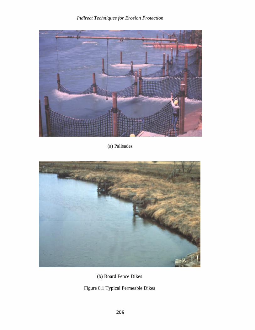
Indirect Techniques for Erosion Protection
206206
(a) Palisades
(b) Board Fence Dikes
Figure 8.1 Typical Permeable Dikes
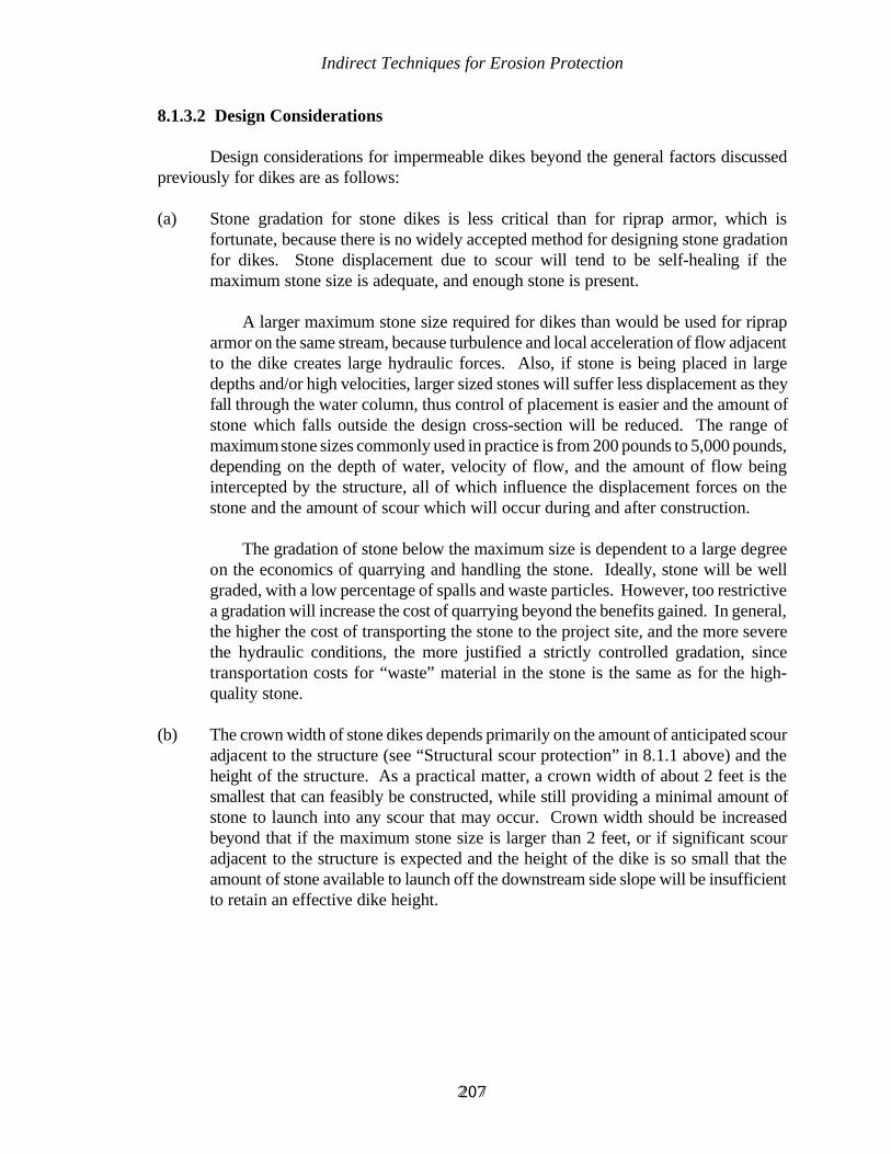
Indirect Techniques for Erosion Protection
207207
8.1.3.2 Design Considerations
Design considerations for impermeable dikes beyond the general factors discussedpreviously for dikes are as follows:
(a) Stone gradation for stone dikes is less critical than for riprap armor, which isfortunate, because there is no widely accepted method for designing stone gradationfor dikes. Stone displacement due to scour will tend to be self-healing if themaximum stone size is adequate, and enough stone is present.
A larger maximum stone size required for dikes than would be used for riprap
armor on the same stream, because turbulence and local acceleration of flow adjacentto the dike creates large hydraulic forces. Also, if stone is being placed in largedepths and/or high velocities, larger sized stones will suffer less displacement as theyfall through the water column, thus control of placement is easier and the amount ofstone which falls outside the design cross-section will be reduced. The range ofmaximum stone sizes commonly used in practice is from 200 pounds to 5,000 pounds,depending on the depth of water, velocity of flow, and the amount of flow beingintercepted by the structure, all of which influence the displacement forces on thestone and the amount of scour which will occur during and after construction.
The gradation of stone below the maximum size is dependent to a large degreeon the economics of quarrying and handling the stone. Ideally, stone will be wellgraded, with a low percentage of spalls and waste particles. However, too restrictivea gradation will increase the cost of quarrying beyond the benefits gained. In general,the higher the cost of transporting the stone to the project site, and the more severethe hydraulic conditions, the more justified a strictly controlled gradation, sincetransportation costs for “waste” material in the stone is the same as for the high-quality stone.
(b) The crown width of stone dikes depends primarily on the amount of anticipated scouradjacent to the structure (see “Structural scour protection” in 8.1.1 above) and theheight of the structure. As a practical matter, a crown width of about 2 feet is thesmallest that can feasibly be constructed, while still providing a minimal amount ofstone to launch into any scour that may occur. Crown width should be increasedbeyond that if the maximum stone size is larger than 2 feet, or if significant scouradjacent to the structure is expected and the height of the dike is so small that theamount of stone available to launch off the downstream side slope will be insufficientto retain an effective dike height.

Indirect Techniques for Erosion Protection
208208
Figure 8.2 Typical Impermeable Dikes
Indirect Techniques for Erosion Protection
209209
The method to be used to construct the dikes may also influence the choice ofcrown width. If land-based equipment is to be used, but the area where a dike is tobe constructed is underwater or otherwise impassable, specifying a crown wideenough for the operation of hauling and handling equipment should be considered,since the additional crown width will strengthen the dike as well as expeditingconstruction. Whether this is cost effective for a given structure will depend on thecapabilities of the work force, the cost of stone, and the height of the structure, sincethe additional volume of stone required for a wider crown will increase exponentiallywith the height of the structure.
(c) The slope of natural repose can be specified for side slopes of stone dikes. Providingextra stone to launch into any scour hole that may occur adjacent to the structure canbe accomplished more efficiently by increasing the crown width, as discussed in“Structural scour protection” in 8.1.1 above, than by attempting to construct a flatterside slope to accomplish the same purpose. Specifying the slope of natural reposesimplifies construction, because then only the elevation and crown width of a dikerequire control in the latter stages of construction, which is especially advantageousif the side slopes of a dike are underwater. For pre-construction estimates of stonequantities, the slope of natural repose is commonly assumed to be 1 vertical on 1.5horizontal, although some variation can be expected depending on stone gradation,construction procedures, and site conditions.
(d) The slope of the riverward end of a stone dike is often designed flatter than the slopeof natural repose, as discussed in “Structural scour protection” in 8.1.1.
(e) Dikes with a core of earth or other material, with an armor on the surface, are notcommonly used because they provide a smaller factor of safety against unanticipatedscour and other severe hydraulic conditions than do sturdier structures. Baird andKlumpp (1992) report scour problems with such dikes on the Rio Grande River. Afilter of some type between the core material and the armor is likely to be required,which increases the cost. Also, construction of this type of dike underwater is notusually practicable. In spite of these shortcomings, the potential for cost savings maybe considerable if the cost of stone or other conventional dike materials is very high.
8.1.4 RETARDS
The relative advantages and disadvantages of retards were compared to dikes inSection 8.1.1.

Indirect Techniques for Erosion Protection
210210
8.1.4.1 Typical Application
The typical application of retards is where the channel is to be realigned, but the bendcurvature, bank erodibility, debris load, or hydraulic conditions are too severe for dikes to beeffective or economical. In some cases where channel realignment is not a factor, retards maybe the preferred method if less expensive than bank armoring.
8.1.4.2 Design Considerations
Design considerations for retards beyond those discussed in Section 8.1 involvelocation, height, and tiebacks.
(a) If a change in channel alignment is not required, the preferred location for the retardfrom the standpoint of economy and efficiency is at a point slightly riverward from thetoe of the bank slope. The location of the retard in plan view is determined by identifyingthat point on surveyed bank cross-sections, then plotting on a plan view that point'slocation at each cross-section. A smooth alignment can then be drawn through thosepoints which “control” the overall alignment. Those points will be the ones which arefarthest out in the channel. If the existing bank alignment is fairly smooth, then theretard alignment will pass through or near all the “preferred” points. However, if theexisting alignment is irregular, then the retard alignment must necessarily lie riverwardof many of the preferred points. If a pronounced single irregularity causes the retard tobe located unacceptably far out in the channel upstream and downstream of theirregularity, then the alternative is to smooth the bankline irregularity by excavation.
(b) The height, or elevation, of the retard is determined by considering the factors discussedpreviously for dikes. The elevation of the retard can be varied around a bend as theattack against the bank and/or as the erodibility of material varies. This complicatesdesign and construction somewhat, and is seldom done, but does have the potential toincrease the efficiency of the design. The United Nations (1953) described someEuropean work as having the retard highest at the apex of the bend, sloping downwardto a minimum elevation at the upstream and downstream ends. A concern about thatapproach, however, would be that the downstream limb of a bend is often where theattack against the bank is greatest at higher flows, and the risk of a low elevation thereis greater than for a low elevation at the upstream end. This is especially true after thework has been in place long enough for the normal downstream movement of scourpools and bars to have increased the hydraulic forces along the downstream portion ofa retard in a bend.
(c) Tiebacks (sometimes called “baffles”) are mandatory where the retard is located well infront of the bank and in short radius bends, and are recommended in all cases. Forsimplicity of design and construction, they are often of the same structural design as theretard, but can be of a less costly design if site conditions permit a less conservativeapproach. The length of tiebacks is determined by the distance from the bank to the
Indirect Techniques for Erosion Protection
211211
retard. The top elevation of tiebacks is commonly made the same as the retard, althougha lower elevation can be used for a less costly, but less conservative, design.
The spacing of tiebacks can be designed according to the concepts discussedpreviously for spacing of dikes. However, such a design would often be overlyconservative, since the tiebacks are simply used to reinforce the main protection device,the retard itself. The permissible increase in spacing can be determined for a specific siteonly by applying judgement, experience, and the factors discussed in 6.6, “Safety factor.”
General practice is to place tiebacks on the shortest line from the retard to thebank. This is the least costly approach, and provides a compromise between them beingperpendicular to the realigned flow and perpendicular to the existing bankline. The lackof agreement regarding the optimum angle that transverse structures should have withrespect to direction of flow is less troubling for tiebacks than for dikes, since the tiebacksare not the primary component of the work.
Tieback bankhead design should follow the same principles as for dikebankheads, but can be less conservative in many cases since the retard itself will usuallydecrease erosive forces at the tieback bankhead.
8.1.5 PERMEABLE RETARDS
The advantages of permeable retards as compared to impermeable retards are thatthey are equally, if not more, effective when used on streams with relatively highconcentrations of suspended sediment, and are often less costly to construct, since materialsare usually available locally. Typical permeable retards are shown in Figure 8.3.
The disadvantages are that they are less durable than stone retards and some of theother impermeable retard materials, and are usually considered less aesthetic. They alsointerfere to a greater degree with access to the stream channel.
Most aspects of materials and structural design are the same as for permeable dikes(see 8.1.2). Other design considerations beyond those discussed previously for retards areas follows:
(a) Double-row retards are sometimes used to increase structural stability and to furtherreduce flow behind the retard. A double-row design also gives the impression of bettertoe protection, but that may be illusory for rigid retards, since if the first row fails fromtoe scour, the second row is likely to fail eventually also. However, the outer row offlexible double-row retards, such as jacks, can displace downward into a scour hole andstill provide protection to the inner row.
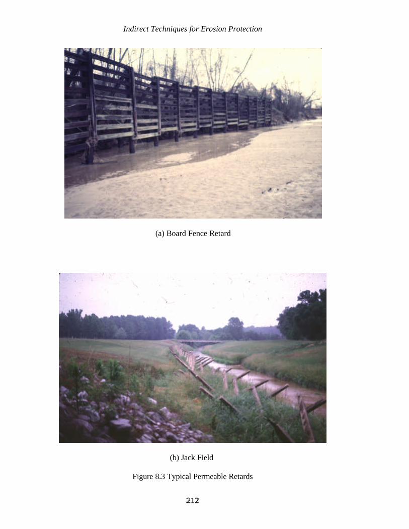
Indirect Techniques for Erosion Protection
212212
(a) Board Fence Retard
(b) Jack Field
Figure 8.3 Typical Permeable Retards

Indirect Techniques for Erosion Protection
213213
Rigid double-row retards are sometimes used as “cribs,” filled with variousmaterials to further reduce velocities behind the retard. This is a site-specific decision,dependent on the economics of filling versus using a less permeable facing design, andon the durability required of the filling material. Using local material such as hay orbrush reduces permeability at low cost, but at the expense of durability, and relies onfuture deposition and vegetation for permanent velocity reduction. A stone fillingprovides permanent toe protection as well as permeability reduction, but requires asubstantial facing to retain the stone, and will add substantially to the cost. Used tires(perforated to reduce buoyancy) provide an inexpensive and durable filling, if regulationspermit such use. However, undermining or deterioration of the crib may result in anunsightly redistribution of the tires along downstream river banks, adding environmentalinsult to the injury of a failed structure.
(b) Some designs, such as fence-type retards, require that the bottom member beapproximately horizontal. Therefore, some leveling of the streambed along the line ofthe structure may be required during construction, which limits the use of these designsto ephemeral streams and minor scour situations, unless a material such as stone is usedto build up the base. In that case, the stone will also serve as toe protection. Otherwise,any leveling of the streambed to expedite construction must be considered as beingtemporary, lasting only until the first flow event.
(c) Carlson and Dodge (1962) present a method for determining the suitability of jackretards for a given situation, and for estimating the amount of deposition likely to beinduced by them.
8.1.6 IMPERMEABLE RETARDS
The relative advantages and disadvantages of impermeable retards as compared topermeable retards were discussed in 8.1.5. Most aspects of materials and structural designare the same as for impermeable dikes (see 8.1.3). An impermeable retard of stone can beconsidered to be a form of longitudinal stone toe, discussed in 7.1.4 and most aspects ofdesign discussed there are applicable to stone retards.
8.2 OTHER FLOW DEFLECTING METHODS
Structures other than dikes and retards may provide a means of altering hydraulicconditions in order to resist bank erosion in bends. One of the most intractable problems ofriver engineering is posed by the coupled processes of deposition of sediment on point barfaces and scour in the thalweg of bends. Several approaches have successfully addressedthese coupled processes in some cases. These approaches alter secondary currents so thatsediment transport away from the toe of the bank is reduced. This results in a more uniformcross-section shape, with shallower thalweg depths and a wider channel at low flow. Theseapproaches include Iowa vanes, bendway weirs, and sills.

Indirect Techniques for Erosion Protection
214214
8.2.1 IOWA VANES
The technique called “Iowa vanes” originated from physical model tests performedby the Iowa Institute of Hydraulic Research for the U.S. Army Corps of Engineers (Odgaardand Kennedy, 1982). The purpose of the model study was to define a bank stabilizationtechnique for the Sacramento River which would be both effective and environmentally soundalthough the proposed solution was not actually implemented. The first field application wassponsored by the Iowa Department of Transportation in 1985 on the East Nishnabotna Rivernear Red Oak, Iowa. Subsequent development of the technique has led to it being patented.At present, the primary use of Iowa vanes is on bank stability problems on small rivers andon local sedimentation problems, such as at water intakes, on larger rivers. Results fromthese works may in time identify broader applications.
Iowa vanes are fully submerged during high flows, but are above the water level atlow flows. The location and orientation of the vanes with respect to flow is critical tosuccess. Also, because success depends upon the structures having a precise effect on thevelocity vectors in the bend, stabilization of the upstream bend is recommended if upstreamchannel migration is likely to change the flow patterns entering the vane system.
Initial evaluation of the East Nishnabotna installation indicated that flowlines throughthe project reach were not affected by the structures (Odgaard and Mosconi, 1987).
8.2.2 BENDWAY WEIRS
Bendway weirs were developed by the U.S. Army Corps of Engineers as a methodto increase channel width in bends on the Mississippi River in order to improve navigationconditions and reduce maintenance dredging requirements (Derrick et al., 1994). They alsoinduce deposition in the thalweg of the bend, which should enhance bank stability and reducethe tendency for scouring velocities in the overbank area during floods. The success ofbendway weirs is based on the premise that the flow over the weir is redirected at an angleperpendicular to the weir. When the weirs are angled upstream, the water is directed awayfrom the outer bank and towards the inner bank, or point bar.
The weirs on the Mississippi River are level-crested stone structures angled upstream,with a crest elevation about 15 feet (4.5 meters) below low water. The design is based onphysical model studies at the Waterways Experiment Station, which indicated that apronounced upstream angle was required for the structures to function properly. The firstsystem was installed in 1990 on the Mississippi River upstream of the mouth of the OhioRiver, and is performing well. That installation and several subsequent ones are beingmonitored, and other installations are planned.
Environmental aspects of bendway weirs appear to be favorable. Since they aresubmerged well below low water level, the detrimental impacts on esthetics and safety which

Indirect Techniques for Erosion Protection
215215
are associated with most other indirect protection techniques are eliminated. Also, byproviding a rocky substrate for benthic organisms and cover for fish, and by altering thevelocity distribution across the cross-section and in the vertical, they improve habitatconditions for some species of aquatic life. Whether detrimental effects would accompanythese beneficial effects in other applications would depend upon the environmental contextof a specific application.
In recent years, bendway weir theory has been applied to small stream applications asa streambank protection measure (Figure 8.4). The first small stream application was in 1993on Harland Creek near Tchula Mississippi where fifty-four bendway weirs were constructed(Derrick, 1997a). Since that time, bendway weirs have been built on numerous small streamsthroughout the country. Some of theses projects have used low-cost, hand placed stone weirs,and weirs constructed of tree trunks and geobags to protect farmland (Derrick, 1997b).Because this is a recently developed technique, the long term success of these structures asa bank stabilization scheme is not known. Further research and monitoring of existingstructures is needed to document the long-term performance and to develop more definitivedesign criteria.

Indirect Techniques for Erosion Protection
216216
(b) Bendway Weirs in Combination with Longitudinal Peaked Stone Toe Protection
Figure 8.4 Bendway Weirs on Small Streams
(a) Bendway Weirs on Harland Creek

217217
CHAPTER 9
VEGETATIVE METHODS FOR EROSION PROTECTION
The two previous chapters addressed structural approaches to erosion protection, inthe form of surface armor and indirect techniques. Vegetation's great potential for use inerosion protection, and the requirement that it be carefully planned and designed using skillsnot usually included in traditional engineering knowledge, merits separate discussion. Thischapter is not an exhaustive treatment, but does present a rational overview of the subject.The latest U.S. Army Corps of Engineers guidance for bioengineering for streambank erosioncontrol is discussed in Appendix B.
9.1 OVERVIEW
Vegetation is the basic component of what is known as “bioengineering” (Schiechtl1980) or biotechnical engineering (Gray and Leiser, 1982; Gray and Sotir, 1996). Schiechtl(1980) states that bioengineering requires “the skills of the engineer, the learning of thebiologist, and the artistry of the landscape architect.” The concept of bioengineering isancient, but there has been much recent research and documentation of the topic. Thepublications just cited, as well as Coppin and Richards (1990), provide comprehensivecoverage, and many other works provide discussion of specialized aspects of the subject.
9.1.1 FUNDAMENTAL CONCEPTS
Vegetation can function as either armor or indirect protection, and in someapplications, can function as both simultaneously. Grassy vegetation and the roots of brushyand woody vegetation function as armor, while brushy and woody vegetation function asindirect protection. The roots of vegetation may also add a degree of geotechnical stabilityto a bank slope through reinforcing the soil.
Some factors which affect the success of a bioengineering approach, such as weatherand the timing and magnitude of streamflows, are beyond the designer's control. Therefore,expert advice, careful planning, and attention to detail are critical to maximizing theprobability of success.
Vegetative Methods for Erosion Protection
218218
Many streambank protection projects include vegetation without conscious thoughtby the designer, since native vegetation often establishes itself once the processes of bankfailure are stopped by structural means. However, if the potential for utilizing vegetation isconsidered from the beginning, then the effectiveness, environmental aspects, and economyof a project can often be significantly improved.
The general principles of erosion protection discussed in Chapter 6 are fully applicableto vegetative work. In fact, because vegetative works are generally more vulnerable thanstructural works, particular care must be taken to insure that the overall approach is sound.Beyond those general principles, the details of successful use of vegetation are even moresite-specific than for structural bank protection. The terminology of the details can sometimesbe confusing, because the technology developed somewhat independently from region toregion over a long time period, whereas widespread interdisciplinary interest in the subject,and broad dissemination of the technology, is fairly recent. Also, the many variations on thebasic techniques add some confusion to the terminology. However, the basic concepts arestraight-forward, and have international and timeless application.
9.1.2 ADVANTAGES
The two obvious advantages of vegetation as erosion protection are its environmentalattractions and its relatively low cost. A third and less obvious attraction is that it canincrease the safety factor of structural protection by enhancing the level of performance.Because many types of vegetative treatment are labor intensive, the cost advantage will beespecially prominent in regions where labor is inexpensive, skilled in agriculture, andconscientious.
9.1.3 DISADVANTAGES
Some characteristics which make vegetation effective and desirable in most situationsmay be disadvantages in other situations. However, many of the following concerns willeither not be applicable for a specific project, or will be acceptable as compromises in lightof vegetation's merits.
The most serious shortcoming is that even well executed vegetative protection cannotbe planned and installed with the same degree of confidence, or with as high a safety factor,as structural protection. This is not to say that vegetation will not be adequate, or will notbe more cost effective than structural protection in a specific situation, but is rather anacknowledgement that structural protection can be designed to function under more severeconditions of hydraulic and geotechnical instability than can vegetation. Vegetation isespecially vulnerable to extremes of weather and inundation before it becomes wellestablished.
Vegetative Methods for Erosion Protection
219219
Quantitative guidance for the use of vegetation in streambank protection is limited,although there has been progress through recent research.
Most vegetative measures have constraints on the season of the year that installationcan be performed. This shortcoming can be mitigated to some degree by advance planningor by developing more than one option for vegetative treatment.
Vegetative treatments often require significant maintenance and management in orderto prevent the following problems:
Growth of vegetation causing a reduction in flood conveyance or causingerosive increases in velocity in adjacent unvegetated areas.
Deterioration of the environmental function of the vegetation due tomismanagement by adjacent landowners, vandalism, or natural causes.
Trunks of woody vegetation or clumps of brushy vegetation on armorrevetment causing local flow anomalies which may damage the armor.
Large trees threatening the integrity of structural protection by root invasionor by toppling and damaging the protection works, or by toppling anddirecting flow into an adjacent unprotected bank.
Roots infiltrating and interfering with internal bank drainage systems, orcausing excess infiltration of water into the bank.
In arid regions, vegetation's ability to reduce soil moisture may be a concern.However, this is not likely to be a serious concern if the native plantecosystem was considered in the initial selection of vegetative species. In anyevent, a riparian strip of vegetation is not likely to harm the groundwaterresource enough to outweigh the positive values of the vegetation.
Many of these problems may be avoided through selection of the appropriatetype, and species or clone of vegetation for the purpose. However, designersrarely have the practical experience or formal training in biotechnology tomake such selections and expert advice must be obtained from qualifiedindividuals in plant biology and bioengineering.
9.1.4 TYPICAL APPLICATIONS
Vegetation is most often used in conjunction with structural protection. Exceptionsmay be made for very small waterways, for areas of low erosion activity, or for situationswhere the consequences of failure are low and there is provision for rehabilitation in case of

Vegetative Methods for Erosion Protection
220220
failure. Vegetation can have a particularly important role in the stabilization of upper bankslopes.
Vegetation is especially appropriate for environmentally sensitive projects, whetherbenefits to recreation, esthetics, or wildlife is the object.
Vegetation is well-suited for incremental construction, either to wait for morefavorable planting conditions for specific types of vegetation or to wait for deposition ofsediments in the area to be planted. Vegetation is also suitable for inexpensive reinforcementor repair of existing erosion protection works in some situations.
Woody vegetation is useful in preventing or repairing scour at or behind top of bank,especially if the scour resulted from an infrequent flood event which is not likely to recurbefore the vegetation becomes effective.
Woody vegetation is sometimes used to prevent floating debris from exiting thechannel during floods and becoming a nuisance in the floodplain.
221221
CHAPTER 10
CONSTRUCTION OF STABILIZATION WORKS
There are two fundamental differences between the construction of bank stabilizationworks and that of more conventional structures. The first difference occurs simply becausepart of the work is often out of sight (underwater). The second difference concerns siteconditions. These affect the design, performance, and even the appropriateness of thetechnique being used. Often conditions change dramatically between design and construction.These changes may be caused by unusually high flows, or may be due to normal streamdynamics. Environmental sensitivity to construction operations may change with the seasonof the year, since nesting, spawning, and other wildlife activities are all seasonal. Also, thetiming of construction affects the success of establishing vegetation. To complicate mattersfurther, the construction operation itself may initiate changes in site conditions. Such changesnot only require the attention of the designer, they often pose problems for constructionpersonnel and contract administrators.
Specialized aspects of the construction of bank stabilization works are sparselydocumented, perhaps because construction personnel tend to focus more on performing workthan on academic reporting. This is in contrast to the practice of engineers and scientists,who are usually encouraged, or even required, to document their research findings andpractical experience.
It would be inappropriate for this text to attempt to deal with construction in termsof the details of plant, labor, materials, administration, and management. These aspects ofconstruction are to a large degree dependent upon organizational policy, local custom andworkforce capability, and the stabilization technique being employed. Therefore, thisdiscussion will concentrate on concepts and ideas which are peculiar to river stabilizationwork, and which are not widely documented. These aspects are easily overlooked by thedesigner when other matters are clamoring for attention, but they should be integrated intothe planning and execution of construction in order to obtain the most effective,environmentally sound, and economical project.
Some detailed factors which relate to construction of specific types of bankstabilization, but which are more pertinent to the selection and design process, have beendiscussed in Chapters 5 and 6.

Construction of Stabilization Works
222222
Concepts of construction will be discussed under these headings:
Coordination of design and construction;Specialized contract provisions;Environmental protection;Specialized construction procedures; andSite preparation and restoration.
10.1 COORDINATION OF DESIGN AND CONSTRUCTION
The designer should encourage communication with, and develop a rapport with,construction personnel by being supportive and cooperative when problems or disagreementsoccur. Communication should begin as early as possible in the planning and design stages.Ideally, the concept of the proposed work would be discussed with construction andoperations personnel, followed by a review of plans and specifications prior to finalization.The formality of these actions can vary, but it is good practice to document the results inorder to prevent future misunderstandings.
The designer should visit the job site occasionally when the work is going well, andfrequently when it is not, not to infer a lack of trust in construction personnel, but simply todemonstrate an understanding of the importance of competent construction. These visits alsofamiliarize the designer with construction practices, as well as informing constructionpersonnel of the factors which went into the design of the work. They can then betterdistinguish between those changes in site conditions which are significant and those which arenot. At the same time, construction personnel should be encouraged to notify the designerof significant site changes.
10.2 SPECIALIZED CONTRACT PROVISIONS
The following areas offer opportunities for insuring that contract provisions providea framework for quality workmanship, fair and efficient contract administration, and amaintainable project:
Specifications and bid items;Restrictions imposed by river conditions;Preconstruction verification of design ;Stone gradation and quality;Specifications for commercial products; andDocumentation of as-built condition.
Specifications should also clearly address environmental aspects of the work, asdiscussed in 10.3.
Construction of Stabilization Works
223223
10.2.1 SPECIFICATIONS AND BID ITEMS
The format and content of specifications for work to be contracted are usuallydictated by organizational policy, with only the technical details left to the engineer'sdiscretion. If that is not the case, then specifications can be developed by obtaining guidespecifications, or specifications for a particular project similar to the one being designed, froman agency or firm accustomed to doing similar work in the region.
The following approach to bid items will expedite contract administration:
Use lump sum bid items for elements of the work for which (1) reliableestimates of quantities can be prepared based on the advertisement for thework, and (2) quantities are not likely to be affected by changed siteconditions, and (3) measurement and payment by unit price would be tedious.Mobilization and demobilization are commonly done this way, but other itemssuch as site clearing, surface drainage work, and small items of excavation(such as for dike bankheads) can also be effectively treated this way.
Use unit price bid items for work which may be significantly affected bychanged site conditions, and for which the actual quantities can be measuredeasily. The unit of measurement should be the simplest one which is a reliableindicator of work performed, such as ton of stone, area of vegetativetreatment, and linear measure of retard.
If more than one stabilization method or material would satisfactorily meet projectrequirements, and the comparative cost of the alternatives cannot be reliably estimatedbeforehand, then alternative bid items can be presented in the advertisement for bids, and thecontract can be awarded for the alternative with the lowest bid price. For example, if eitherof two types of flexible mattress would be satisfactory, then the advertisement for bids couldprovide for either or both to be bid on, and the contract would be awarded for the leastexpensive one. This approach increases the design effort, since the specifications mustaddress all alternatives to be bid on. It is most likely to be feasible when other design factors,such as geotechnical stabilization measures, beginning and ending points, and channelalignment, would be identical with either alternative. A similar approach is commonly usedfor vegetative treatment, with the date that the treatment is accomplished being the variablewhich determines the type of treatment.
If the rate of supply of materials to the site is the controlling factor in the timerequired to complete the work, then provision in the specifications to allow partial paymentto the contractor for stockpiled materials can be helpful in completing the work without delay.This encourages the contractor to stockpile materials if that is required for timely completion,although the capital costs involved will presumably be reflected by an increase in the bid price.An alternative for speedy completion is to specify a compressed time allowance forcompletion, with the contractor being penalized financially for exceeding that time, unlessunusual circumstances beyond the contractor's control were the cause. The risk in this
Construction of Stabilization Works
224224
approach is that legal and administrative constraints on determining and assessing the penaltyfor exceeding the time allowed for completion may prevent the penalty from being highenough to result in any significant acceleration of the contractor's operations.
10.2.2 RESTRICTIONS IMPOSED BY RIVER CONDITIONS
A generally accepted axiom of construction contracting is that only the end productshould be specified, leaving operational procedures to the contractor. However, some riverstabilization projects involve an exception, where it is advisable to impose operationalrestrictions on a contractor if river stages are temporarily too high for effective work. Thismay be necessary to insure that the contractor does not attempt work such as bank grading,placement of filter material, and placement of subaqueous stone when depth of water or flowvelocity are too great for satisfactory results to be ensured. Since it is often impossible toprecisely verify the in-place condition of subaqueous work, specifying the conditions underwhich the work must be done reduces the risk of an inadequate job.
The simplest way to impose such restrictions is to include information on river stagesin the advertisement, and to specify any restrictions that will be imposed on the contractor'soperation when river stage exceeds a given value. Information on river stages is usuallyprovided to prospective bidders in the form of historical records at the nearest gaging station,accompanied by a caveat that historical stages do not necessarily represent the extremeswhich may be experienced during the course of the contract.
An alternative to that approach is to define restrictions on operations in terms of depthof water or current velocity at the jobsite. The risk in this approach is that it involves someconjecture even by the designer, and that bidders unfamiliar with site conditions will certainlynot be able to precisely define the impact of such restrictions on their operation. Therefore,bidders may not have a common basis for preparing bids.
A third alternative presents the most flexible approach from an engineering standpoint,but is potentially the most troublesome from an administrative perspective. That is to statethat operations will be temporarily suspended when, in the judgement of the contractadministrator, river conditions preclude satisfactory execution of the work. If it becomesnecessary to actually impose these undefined restrictions, claims by the contractor foradditional payment may ensue, but that will likely be preferable to the alternative ofcontinuing work under unsatisfactory conditions.
A related but separate issue concerns damage to partially completed work as a resultof the river's flow. Specifications for river stabilization work sometimes include a definitionof the responsibilities of both parties if “unusual” flows or “floods” damage the work inprogress, but interpretation of these clauses often involves legal disagreements when such anevent occurs, or is alleged by the contractor to have occurred. Contract clauses defining“changes in site conditions” versus “conditions that would have reasonably been anticipated,”
Construction of Stabilization Works
225225
and clauses concerning “acts of God” may enter the fray, with final resolution often restingon legal rather than engineering determinations.
10.2.3 PRECONSTRUCTION VERIFICATION OF DESIGN
If site conditions are likely to change between design and construction to such adegree that details of the work will require modification, provision should be made for thisin the contract. An effective procedure is to advertise for bids based on general siteconditions, showing sufficient design detail to allow confident bidding, and to state in thespecifications that details of the work will be provided prior to notice to proceed with thework. The site can then be surveyed and inspected at the last moment that allows detailedplans for the work to be finalized and furnished to construction personnel on schedule. Thepossibility of a claim for changed site conditions still exists, but this procedure reduces thatrisk. It also provides for the most effective and efficient final design, and is especially usefulin emergency situations or to meet a compressed schedule for project completion.
10.2.4 STONE GRADATION AND QUALITY
Appendix A contains detailed guidance for designing the gradation for stone armorfor a specific site. However, it is not usually essential that precisely that gradation bespecified. Stone of a similar and equally effective gradation may be commonly used in thearea; if so, it can usually be obtained at a lower cost, and with a high probability of meetingthe specification without intensive inspection. Even if the commonly used gradation requiresa slightly greater blanket thickness total cost may still be less than if a slightly thinner blanketof a “new” gradation is specified, and the safety factor will be greater.
If standard specifications for stone gradation and quality do not exist within one's ownorganization, it is advisable to obtain guidance from large construction organizations in theregion. Such guidance should include specification of stone quality, testing and inspectionprocedures, and a list of quarries known to be capable of producing acceptable stone, as wellas standard gradations.
Verifying that the gradation and quality of stone produced for the project meetsspecifications can be difficult, because determining the precise gradation of quarried stonerequires tedious and expensive handling of large quantities. Determining stone quality alsorequires sophisticated and expensive testing. These difficulties can be reduced by:
Specifying a standard gradation, as discussed above;
Minimizing the number of different gradations used in a contract;
Construction of Stabilization Works
226226
Listing in the contract those quarries known to be capable of producing stoneof acceptable quality, and requiring that the contractor produce certificationfrom the quarry that the stone does meet specifications; and
Using personnel experienced in stone work for contract inspection.
10.2.5 SPECIFICATIONS FOR COMMERCIAL PRODUCTS
Section 6.5 discussed the use of manufacturers' recommendations in the design phaseof a project. The specification phase often poses a dilemma - should the designer specify aparticular trade name product and include the manufacturer's specifications for installation,or should the designer allow the use of any one of a group of similar products, all of whichhave similar installation specifications? The decision depends upon two factors:
Whether the work is to be advertised for bids, with the contractor furnishingthe materials, or whether materials are instead to be purchased by one's ownorganization or the project sponsor. The significance of this factor is that ifthe contractor is to furnish the materials, then the specifications must not besubject to misinterpretation which might result in the use of unsuitablematerials.
Organizational policy regarding the use of trade names in specifications asopposed to “generic” specifications. If policy allows, careful use of tradenames eliminates ambiguity without requiring lengthy generic specifications.However, the potential exists for overlooking other suitable, and perhaps lesscostly, products. This difficulty can be addressed by using the phrase “orequal” to trade names. However, differences of opinion among engineeringpersonnel, contract administration personnel, and the contractor as to thedefinition of “equal,” and the procedure for judging equality, sometimesresults in significant misunderstandings.
In summary, the specification writer's goal is to ensure that essential aspects of thematerials and the installation are satisfied, without unduly restricting choice of materials andequipment. Such restriction may result in protests by unsuccessful bidders and/orunnecessarily high project costs. The policy of the responsible organization will determinethe most feasible specification structure to accomplish this.
10.2.6 DOCUMENTATION OF AS-BUILT CONDITION
Documentation of the as-built condition of a bank stabilization project is essential notonly for quality control of the construction, but also for future inspection and maintenanceof the work. The most thorough way to satisfy this need is to make a comprehensive surveyof the entire project area immediately after construction, noting all features of the work on
Construction of Stabilization Works
227227
the survey. The survey would include the entire channel in the area of the work, and wouldextend far enough upstream and downstream to allow detection of channel migration or bedscour which might become a threat to the work. Documenting channel bed elevations in thevicinity of the work is especially critical, since toe scour is often the greatest threat to thework.
The survey which was used for detailed design will often satisfy this requirement if nosignificant channel changes occurred during construction. It can simply be amended toinclude details of the work and changes in site conditions during construction.
If a comprehensive survey is beyond the means of the project sponsor, and the streamis small enough to visually observe future changes that would threaten the work, it may besufficient to simply retain the contract plans and specifications, supplemented by photographicdocumentation. Ground-level photographs from documented points as the constructionproceeds are useful for contract inspection as well as for future monitoring of the work.Aerial views are particularly useful for future monitoring of major upstream and downstreamchanges. Making the photographs can be the duty of either the contractor, the inspectionpersonnel, or the designer.
It may be expedient to specify in the contract that the contractor will furnish thecapability to make the as-built survey, and any other surveys required during the course of thework. Surveys during the course of the work may be required for measurement of quantities,or for design adjustments if site conditions are unstable. If surveys by the contractor are tobe used for measurement of pay quantities, it is good practice to insure that they are certifiedby a professional surveyor. Organizational policy may impose other restrictions as well.
10.3 ENVIRONMENTAL CONSIDERATIONS
The impact of construction operations on environmental quality is often temporaryif the specifications include environmental features and the operations are well-managed.Since economics will often govern construction operations if left totally to the contractor,allowable methods of operation, or alternately, methods which are not permissible, should beclearly specified if environmental aspects are critical. Critical habitat areas, vegetation, orother sensitive areas not to be disturbed should be identified as being outside the constructionright-of way. Environmental features of the work should be addressed in the specificationsand during construction as thoroughly as engineering features of the work.
Control of surface water and erosion and sedimentation during construction is alwaysgood practice. The design of permanent measures was discussed in 6.4, but other, moretemporary, measures may be a legal requirement for the political jurisdiction in which thework is being done. Minimizing site disturbance and revegetating areas disturbed byconstruction are always desirable measures, and are examples of measures that may berequired by ordinance. Disposal of clearing debris and excavated material should be done inan environmentally sensitive manner.
Construction of Stabilization Works
228228
Ecologically sensitive periods such as spawning and nesting should be considered inthe timing of construction. This is particularly compelling if threatened or endangered speciesare involved. A potential difficulty is that nesting sites may not be known at the time acontract is issued, in which case the specifications should provide for a conflict resolutionprocedure that will be environmentally sound, but that is also fair to the contractor. Acontract modification and extra payment may be necessary if construction operations aresignificantly disrupted by unforeseen circumstances. An example of a species-specificapproach used by the U.S. Army Corps of Engineers on the Sacramento River, California, forsites at which bank stabilization work could not feasibly be performed before or after bankswallow nesting season, was to cover the bank with plastic sheeting prior to the nestingseason. This forced the swallows to nest at other suitable sites not scheduled for bankprotection.
It is advisable to consult with appropriate agencies, organizations, and environmentalexperts to define the construction practices that are required or recommended for a particularregion.
10.4 SPECIALIZED CONSTRUCTION PROCEDURES
The impact of construction procedures on project economics and the selection of abank stabilization method was discussed in 5.3. This section presents some specificconstruction approaches that may result in a more efficient and effective job. Theseapproaches are discussed under the following headings:
Access for construction equipment;Sequence of construction;Subaqueous placement of stone or similar materials; andProcedures for proprietary products.
10.4.1 ACCESS FOR CONSTRUCTION EQUIPMENT
On small streams, the choice of access is a matter of weighing the trafficability,environmental impacts, and real estate aspects of alternate routes. Fortunately, the mosttrafficable route often has the least environmental impact. In some cases, the streambed,especially sand and gravel bars, may be suitable for maneuvering of construction equipment.The environmental impact may be acceptable, especially if the need for clearing of vegetationalong the streambank is reduced. On streams with high bed material transport, the next flowevent will likely obliterate any traces of construction activity in the streambed. However, itis advisable to be prepared to provide alternative access, because rapid increases instreamflow or undetected areas of “quicksand” can be hazardous to streambed operations.
On navigable streams, the use of floating plant expedites construction and reducescosts and environmental impacts, and on larger streams is in fact the only feasible way to
Construction of Stabilization Works
229229
construct most works. If the stream is not navigable, but sufficient water for floatation existsat the worksite, portable barges can be used as access ways or working platforms forequipment and materials. This may allow the use of smaller machines than if all work isconstructed with shore-based equipment, and will provide environmental benefits by reducingsite disturbance from on-shore working and staging areas.
The procurement of rights of way should also consider the need for permanent accessfor monitoring and maintaining the completed work.
10.4.2 SEQUENCE OF CONSTRUCTION
(a) For projects which are not likely to have significant channel changes during construction,sequence of operations can be left to the discretion of construction personnel so that themost efficient procedure can be used.
However, a common practice is to specify that construction begin at the upstreamend of each worksite. This may seem to be inconsistent with the principle stated in 6.1.1that the downstream end of the work is usually the most vulnerable to damage.However, the apparent discrepancy is resolved by noting that vulnerability of thedownstream end is a relatively long-term process, related to the opposite bar movingdownvalley and encroaching into the channel. Conversely, a construction operation willbe of relatively short duration, during which the attack on the downstream end is unlikelyto increase. Thus, at least for armor protection, the tradition of beginning work at theupstream end probably stems from a fear that bank erosion and channel migration of theupstream portion of a bend while construction is underway might upset channelalignment more severely than similar erosion downstream during the work. For indirectprotection, a more tangible case can be made for beginning upstream. Completed orpartially completed indirect protection structures upstream often reduce streamflowattack on the structures downstream as they are being built, sometimes to the point ofinducing deposition, thus reducing the quantity of materials required for the downstreamstructures. The result is a de facto “incremental construction” approach. However,significant amounts of induced deposition at the site of uncompleted structuresdownstream may dictate changes in design or construction procedures, which may inturn require extra contract administrative effort, but with the reward that total cost ofthe work is often reduced.
Theoretically, a case can be made for beginning construction at the point on thechannel that maximum erosion is occurring, then completing construction as rapidly aspossible in both directions. This is rarely done in practice because it requires twoconcurrent operations, which may limit the number of contractors capable of the workand increase the cost of the work. For emergency jobs, though, or situations where rapiderosion is occurring, such an approach may be advisable.
Construction of Stabilization Works
230230
(b) In all cases, it is advisable to construct the toe protection component as early in theoperation as is practicable.
(c) For projects involving large quantities of armor protection and a long constructionperiod, it may be advisable to place the armor in strips proceeding up the bank slope,with the lowest strip following immediately behind the slope preparation. This reducesthe probability of a rapid rise in water level overtopping and eroding the unarmoredportion of the slope. A similar precaution is to limit the distance that slope preparationoperations can precede completion of slope armoring. That limit may also be stated interms of maximum allowable time interval between the two operations.
(d) The most economical procedure for construction of stone dikes in flowing water is toconstruct them in vertical increments, or “lifts,” if a significant amount of flow will beintercepted by the structure during construction. If the dike is constructed to full gradein one lift, a significant scour hole is likely to develop ahead of stone placement, whichwill increase the amount of stone substantially over the original estimate.
Even if the lift procedure is used, some overrun due to scour and stonedisplacement will occur, and should be provided for in the estimate of required stonequantity. The amount of overrun will vary widely due to the following factors:
Amount of flow intercepted by the structure;Erodibility of the bed material;Rate of stone placement (rapid placement reduces overrun);Gradation of the stone (larger stone reduces overrun); andHeight of the dike (higher structures increase overrun).
No quantitative guidance exists for estimating this overrun for a given situation;therefore, it is usually based on experience. As an example, for dikes on the lowerMississippi River, which are normally constructed in lifts of about 10 feet in height,common practice for estimating the overrun is to assume an average bed scour of 5 feetin front of stone placement in the initial lift only.
Placing a “blanket” of stone ahead of the placement of the initial lift will alsoreduce overrun due to scour. However, placement of stone in a blanket takes longerthan placing an equivalent amount of stone in a “peaked” section within the ultimate dikecross-section. Therefore, the reduction in scour provided by the blanket is offset tosome degree by the longer period of time required to complete the initial lift.
(e) For multi-stage construction of dikes, stone should be placed in the downstream part ofthe dike cross-section first, because a scour hole will occur downstream of the stonealmost immediately as a “plunge pool” forms from flow over the stone. Placingsubsequent lifts of stone in the upstream part of the dike cross-section will require lessstone than if subsequent lifts were placed in the downstream scour hole.
Construction of Stabilization Works
231231
(f) Alternatives available to the construction forces if specifications call for a dike crownwidth too narrow for the operation of construction equipment are to:
Construct “turn-arounds,” or maneuvering areas, by widening the crown atintervals along the dike. The expense of doing this will of course bereflected, at least indirectly, in the bid price for the work if the work iscontracted out.
Construct the top portion of the dike (that portion which is higher than theelevation at which there is a crown width sufficient for hauling and handlingstone) as a separate operation, in which stone that was previously“stockpiled” alongside the dike, but outside the specified dike cross-section,is pulled up and into the design cross-section. The piece of equipment whichperforms this operation literally backs toward the end of the dike, finishingthe dike as it proceeds. Some inefficiency is involved in this method, andsome stone is inevitably left outside the design cross-section, especially ifsome of the stockpiled stone is underwater.
(g) Stone dikes can be successfully constructed even if the entire structure riverward of thebankline is underwater during construction, although careful control of the operation isnecessary. Precise control of the profile and crown width of the finished structure is notfeasible, but the structure will be functional nevertheless. An overrun in quantity islikely, because of less precise placement and increased stone displacement by the flowover the structure. This overrun will be offset in some cases by the relief provided byflow over the structure that would otherwise have been diverted around the end of thedike during construction, causing scour ahead of it, had it been above water duringconstruction.
10.4.3 SUBAQUEOUS PLACEMENT OF STONE OR SIMILAR MATERIALS
Conventional draglines and bucket machines of all descriptions can be usedsuccessfully to place stone fill underwater. Bottom-dumping hopper barges can be used toincrease rate of placement. This practice is more common in European practice than in theUnited States. Lacking such specialized equipment, ingenious use of available equipment,such as coal hoppers mounted between pontoon barges, can expedite the work.
Subaqueous stone paving or granular filters can be placed more efficiently byspecifying the quantity in terms of weight or volume per unit of area covered rather than interms of blanket thickness. In-place thickness is difficult to measure underwater, andadequate coverage can be obtained by careful placement of the material using a grid systemand pre-placement allocation of the amount of material to be placed per grid unit (forexample, 7 tons per 100 square feet, in lieu of a paving thickness of 15 inches). Regardlessof the placement and measurement procedure, the specified quantity should be greater than

Construction of Stabilization Works
232232
that required for the design thickness in order to compensate for the uncertainties ofsubaqueous placement.
Likewise, a subaqueous longitudinal toe dike to provide launching stone for toeprotection can be placed at a rate per linear distance along the bank rather than to a specifiedheight or cross-section shape (for example, 2.1 tons per linear foot of bank in lieu of a peakeddike 5 feet high).
There are many ways to control the horizontal position of subaqueous placementoperations once shoreline survey points are established. Buoys, driven piles, and moored oranchored barges are common practices. Sophisticated electronic survey techniques expeditethese controls, and may eliminate the need for stationary markers completely in some cases.
10.4.4 PROCEDURES FOR PROPRIETARY PRODUCTS
Some proprietary products have specialized procedures and equipment associatedwith them. In some cases, those procedures and equipment may be necessary for satisfactorywork; for example, restrictions on permissible height from which to drop stone on engineeringfabric, or the use of frames to lift and place prefabricated mattresses. In other cases, they maysimply expedite the work; for example, metal “templates” for filling gabions. Those whichare necessary should be directed in the specifications. Regarding those procedures andequipment which merely expedite the work, construction personnel or prospective contractorsshould be made aware of them, with choice of use being their prerogative. This may be doneby providing points of contact for manufacturers' representatives in the specifications. Somemanufacturers will provide on-site assistance during construction.
10.5 SITE PREPARATION AND RESTORATION
Most aspects of site preparation and restoration are inherent in the topics discussedpreviously in this chapter. However, the following points are worthy of separate mentionhere.
Subgrade preparation is especially important for armor protection. Debris whichinterferes with placement of the armor or filter material must be removed. Freshly gradedslopes are especially susceptible to erosion from surface drainage prior to placement of thearmor, therefore preparing the site to control surface drainage may be critical.
Debris which would hinder proper construction of dikes or retards must be removed.It can sometimes be placed in a manner to enhance the work by providing additional indirectprotection to the bank.
Restoring access routes to the original condition, but perhaps with additional erosioncontrol measures, may be appropriate for some projects. For other projects, leaving them
Construction of Stabilization Works
233233
with improved trafficability may be preferable. The choice depends upon the potential futureneed for inspection and maintenance of the project, the landowners' desires, andenvironmental considerations. A factor for projects involving trenchfill or other protectionmethods which depend upon post-project erosion to a predetermined bankline is that hard-surfaced ramps or roads riverward of the structure sometimes resist erosion more than theadjacent natural bank material, perhaps to the detriment of obtaining the desired bankline ina timely manner. In any case, disposition of access roads or ramps should be clearly statedin the easements and in the specifications.
If the project involves stockpiling of stone or similar material prior to placement in thework, restoration of stockpile areas must be addressed. Depending upon the landuse, residualmaterial may be a nuisance after construction, but completely removing it from the naturalground surface without disturbing topsoil and drainage is difficult. To prevent theseproblems, it may be appropriate to specify that such material be placed on a pad of naturalmaterial or on skids of metal, wood, or engineering fabric to prevent it from becoming buriedin the existing topsoil. The stockpile area site can then easily be restored to natural conditionsafter construction.

Construction of Stabilization Works
234234
235235
CHAPTER 11
MONITORING AND MAINTENANCE OF STABILIZATION WORKS
This chapter presents concepts for effectively monitoring riverbank stabilizationworks, for determining the need for maintenance and repair, and for designing repairs ifnecessary. Previous chapters have discussed the characteristics of river behavior and thecharacteristics of the different types of stabilization work, and the application of those topicsto the design of stabilization work. Those topics are equally applicable to monitoring andmaintaining the work. This chapter does not present comprehensive details of maintenanceand repair techniques for the many types of stabilization work, because to do so would beboth tedious and redundant. Neither does this chapter address maintenance aspects of floodcontrol projects, except where those aspects are directly related to bank stabilization works.
11.1 IMPORTANCE OF MONITORING AND MAINTENANCE
Monitoring and maintenance of bank stabilization works are essential in order toensure successful performance over the lifespan of the project. Even properly designed worksoften require some maintenance eventually. Because of the dynamic nature of streams, a lackof maintenance often results in major failures, which become progressively more difficult andexpensive to repair. Therefore, monitoring of stabilization works is more important than forstructures in a static environment. Because critical components of the work are oftenunderwater, thus not visible to simple observation, monitoring often involves significant butcost-effective effort and expense. Foresight is essential, because it is too late to begin aneffective monitoring program once unforeseen damage requires major repair.
For works to be maintained by a governmental agency, there may be formalrequirements, or at least guidance, for monitoring and maintenance. In the case of works tobe maintained by a local sponsor, it may be necessary for the constructing agency to provideto the sponsor a manual describing monitoring and maintenance requirements. Theapplicability of, and the necessity for rigidly adhering to, these official requirements variesfrom project to project. However, the project manager should be aware that officialrequirements may exist, and should satisfy them as appropriate, keeping in mind thatsatisfying official requirements is a means to an end - maintaining functional work - and notan end in itself.
Monitoring and Maintenance of Stabilization Works
236236
11.2 MONITORING
11.2.1 PURPOSES
An effective monitoring program accomplishes three things:
Detects the need for maintenance or repair in a timely fashion.
Provides a basis for designing repairs, if required.
Provides valuable insight into stream behavior and performance ofstabilization work, which can be applied to future projects.
11.2.2 CONCEPTS
Ideally, the critical elements of river characteristics and their impact on the design ofthe protection work will have been considered and documented when the work was plannedand designed. The most vulnerable aspects of the work will also have been identified as partof the planning and design process. Also, the as-built condition of the work will have beendocumented as part of the construction operation. If some of this information is missing orwas never considered, monitoring activities will be compromised, but will still be worthwhile.
It is essential that monitoring detect any events or changes in stream characteristicsor the condition of the work that exceed design assumptions. Although the stream itself isnow the judge of whether the work is adequate, the fallacy in total reliance upon short-termobservations of the performance of the work is that, in the absence of a rare event, designconditions will not be experienced until some future time. Therefore, all conclusions basedon monitoring should be tempered by consideration of the actual conditions that theprotection work has experienced.
Monitoring should include upstream and downstream conditions that may have futureimpacts upon the project. Examples are:
Changes in upstream channel alignment may threaten bank stabilization worksdownstream.
Channelization work may induce degradation upstream and may changehydraulic and geomorphic conditions downstream.
Significant changes in operating procedures of reservoirs upstream of theproject site, or significant land use changes may change hydraulic andgeotechnical parameters at the site.
Monitoring and Maintenance of Stabilization Works
237237
Those topics have been addressed in previous chapters, but their relevancy does notdiminish once a bank stabilization project has been completed.
The key word for monitoring is “comparability.” For visual inspection, consider theseason of the year and precedent flows. Observations made in late winter following highflows, with dormant vegetation, are not totally comparable to observations made in latesummer. The perspective of sequential photographs should be comparable. Cross-sectionsand hydraulic data should be taken at comparable points and by comparable methods.
11.2.3 PRIMARY ELEMENTS
Available resources usually don't permit a monitoring program which obtains allpossible or even all desirable data. The following discussion will re-emphasize someimportant concepts and identify those elements most critical to monitoring protection work.The primary elements are:
Site inspection;Site surveys;Geomorphic observations;Hydrologic and hydraulic data;Geotechnical data; andEnvironmental aspects.
Within the scope of these primary elements, Mellema (1987) provides sound adviceby stating that periodic fixed cross sections, gages to monitor river stages, and photographsare the basic monitoring tools. More sophisticated measures are often worthwhile, but mustbe weighed in the context of project requirements and long-term commitment of resources.Pickett and Brown (1977) provide an extensive listing of potential data collection activities,from which those appropriate for a specific project can be selected.
11.2.3.1 Site Inspection
On-site inspection of the work itself is certainly the primary and most cost-effectivemonitoring element. Photographs made during these inspections are an invaluable supplementto written notes because they document conditions more reliably than memory or writtenobservations, they can be referred to in the office while designing repairs if required, and theyprovide useful evidence of maintenance needs if competition with other projects formaintenance funds is a factor. Inspection should extend as far upstream and downstream ofthe project reach as is necessary to ensure that events elsewhere are not threatening theproject.
If stream depths permit, wading and probing may reveal scour holes and displacementof armor materials at the toe of a revetment.
Monitoring and Maintenance of Stabilization Works
238238
Interviews with local persons to obtain additional information, and encouragingreliable local observers to report significant observations to those responsible for monitoring,is often worthwhile.
11.2.3.2 Site Surveys
Surveys are particularly important where the water level does not permit visualobservation of the toe and lower bank slope, or where a primary concern is scour during highflows. Cross-sections of the bank, extending well past the toe, are the most reliable anduseful type of survey, since toe deepening and undermining are the major factors in manyfailures. Handling of large amounts of data can be expedited by the use of computers.
Thalweg profiles require less effort than bank cross-sections, but are less reliable asto repeatability and accurate documentation of significant changes, therefore should besupplemented by cross-sections at representative locations.
Surveys taken during low flow periods may not adequately document conditions,particularly at the toe of the bank in bends, where scour and deposition may occur during highand low flows, respectively. Surveying during high flow periods is more difficult andexpensive than during low flows, but may be advisable where adequacy of protection againsttoe scour is questionable.
The level of survey detail required for routine monitoring will usually be less than thatwhich will be required if the need for repair work is detected. Monitoring surveys must becomparable to previous surveys, but surveys for design of repairs should be tailored to thespecific one-time need. Routine monitoring surveys will, however, provide a basis fordefining the additional level of detail required for surveys to be used in designing repairs.
11.2.3.3 Geomorphic Observations
Changes in overall planform or local channel alignment can threaten the integrity ofthe work. Application of the principles discussed in 6.1 will determine when such threatsexist. Also, the work itself may affect downstream conditions. The length of stream requiringgeomorphic observation will depend upon the overall stream stability and the type and extentof protection work.
Aerial inspection is often a cost-effective technique for monitoring geomorphicconditions. Oblique and/or vertical aerial photography is particularly useful in documentingprogressive changes. Vertical photography should provide sufficient overlap of adjacentphotographs to allow at least a qualitative stereoscopic analysis of changes in bar heights andbank slope steepness. If detailed mapping is justified, vertical aerial photography can begeodetically controlled to permit mapping of the channel topography above water.
Monitoring and Maintenance of Stabilization Works
239239
Significant changes in bed material composition in the project reach can affect theperformance of the work, either favorably or unfavorably. For example, an increase in theamount or size of gravel in the bed may limit bed scour, but may also cause changes inplanform which could adversely affect the work. Changes in bed material can be monitoredeither informally by detailed visual observation and photographic documentation, or througha formally designed sampling and analysis program. A formal program is not likely to be cost-effective solely for monitoring the protection work itself, but may sometimes be justified aspart of a broader study.
11.2.3.4 Hydraulic Data
Initial collection and analysis of essential hydraulic data will presumably have beendone in planning and design of the protection work. Hydraulic monitoring should concentrateon those parameters which were identified during planning and design as being most criticalto the adequacy of the work. Over the short-term, routine monitoring of hydraulicparameters will usually not provide a basis for changing design criteria that are based onlongterm probabilities, but it may provide an indication of whether or not design assumptionswere reasonable.
Velocity is usually the most critical element for riprap protection. Also, if thealignment of flow into the protection work is changing significantly, the effect on thecurvature correction factor for riprap design velocity should be evaluated.
Hydraulic data in the form of long-term stage-discharge relationships can indicatewhether streambed degradation is cause for concern. These observations are best made atstations downstream of the project, so that degradation can be detected in time to reinforcethe toe of the work or take other remedial action if necessary.
11.2.3.5 Geotechnical Data
The degree of geotechnical monitoring required is highly site-specific. A simple ruleis that if critical geotechnical parameters cannot be monitored visually, then sophisticateddevices such as piezometers and slope indicators may be required, especially if there wassome degree of uncertainty in the original design, or if the consequences of failure would behigh. In other cases, a visual inspection for proper function of internal drains, surfaceindications of slope settlement, and similar items may be sufficient.
Monitoring and Maintenance of Stabilization Works
240240
11.2.3.6 Environmental Aspects
The listing of this element last does not detract from its importance. It simplyacknowledges that the project must perform its bank stabilization function adequately, elseenvironmental function will likely be compromised as well. Also, some of the engineeringelements just discussed, particularly geomorphology and hydraulics, have environmentalimplications as well.
The environmental parameters which should be monitored can be defined by reviewingthe environmental factors which were pertinent to the selection of the protection method.Environmental specialists should be involved in the monitoring as appropriate.
11.2.4 FREQUENCY OF MONITORING
The first few years after construction and the first major flood flow are the two criticalperiods in the life of bank protection works. Monitoring should be intensified during theseperiods. Although events such as toe scour and scour at termination points and bank headsmay not fully develop during this period, major problem areas will usually become evident,and will help define the required monitoring intensity for the long-term. As a minimum,inspect the work immediately following the high flow season. If a need for immediatereconstruction or repairs is discovered, then the process of design and construction can becompleted before the next high flow season.
During these critical periods, an additional inspection during low water levels in latesummer will allow an evaluation of the portion of the work that may have been underwaterduring earlier inspections, as well as an evaluation of vegetative growth during the summer.
Problems with gradual deterioration of structural components does not carry theurgency of major changes in channel geometry or alignment, or major flaws in the initialdesign of the work. Therefore, any reasonable interval of monitoring will suffice for thatelement.
Beyond these general guidelines, frequency of monitoring is determined either byregulation) or by engineering judgement, whichever results in the most frequent monitoring.Engineering judgement should take into account the safety factor of the original design andthe consequences of failure (see 6.6), the severity of hydraulic conditions, and the degree ofgeomorphic instability of the stream. Monitoring of specific conditions such as channelvelocity, waves, or ice forces should be timed to coincide with the occurrence of criticalevents if possible.
Monitoring and Maintenance of Stabilization Works
241241
11.2.5 PERSONNEL
Ideally, each project will have a single person who is responsible for the technicalaspects of its monitoring, and for providing evaluation and recommendations to decision-makers, although other persons will be involved as appropriate for specialized technical input,and for training and continuity in the event of personnel changes.
Agency regulations may specify the personnel to be involved in monitoring,particularly if the bank protection work is part of a broader project purpose, such as floodcontrol. However, even if such guidance exists for a particular project, it may be advisableto supplement those required personnel with others who were involved in the design of thework, such as environmental specialists, vegetative experts, or others. The cost of involvingsuch specialists will be small compared to the potential benefits.
If circumstances prevent the close involvement of those who planned and designedthe work, it is even more important that the non-technical personnel who are responsible formonitoring and maintenance be involved early in the planning and design process. In additionto perhaps having provided useful input at that point, they will also be better prepared to latermonitor the work.
11.2.6 POINTS REQUIRING SPECIAL ATTENTION
Particular attention must be paid to two areas at which scour or failures can quicklylead to the work becoming ineffective or requiring extensive rehabilitation:
The toe of the protection.
Bank connections at the upstream and downstream ends of the protection, orin the case of indirect protection, all bank connections.
Other important items to be monitored will vary with the type of protection andstream characteristics. Examples are:
Interior drainage components of impermeable revetments. Evidence of voidsforming underneath rigid armor should be especially noted.
Upper bank slope where structural components transition to the natural bankmaterial or vegetation, including areas where overbank drainage returns to thestream. Flood flows may have scoured or otherwise disturbed this zone.Although this may not result in major failure of the work, it can generateconsiderable concern for the landowner or sponsor.
Monitoring and Maintenance of Stabilization Works
242242
Displacement or separation of armor material which exposes erodible bankmaterial. Such displacement can be due to hydraulic forces, to geotechnicalfactors such as slope settlement or piping, or to vegetative disruption.
Gradual deterioration of mattress elements or retard and dike components.
Condition of planted and volunteer vegetation.
11.2.7 LEVELS OF MONITORING EFFORTS
11.2.7.1 Level 1 Monitoring
Level 1 monitoring effort consists of a field reconnaissance and visual observation ofthe site, and a written report detailing the present conditions found at the site. This writtenreport can also include a comparison between the present existing conditions and previousfindings recorded during other site visits or supplemental data from aerial photographs orother sources and analysis of future stream movement and behavior (down valley migration,degradation, etc.). If an existing streambank protection project is within the study reach, ananalysis of the performance of this project can also be included in this report.
11.2.7.2 Level 2 Monitoring
Level 2 monitoring effort consists of all activities performed during a Level 1monitoring effort plus a permanent photographic and/or videotape record of the project area.Photos should be shot from fixed and marked locations so that comparisons can be made overtime. All photos should be indexed and accompanied by well written descriptions of thecontents of the photographs plus the location where the photo was shot.
11.2.7.3 Level 3 Monitoring
Level 3 monitoring effort consists of all activities performed during a Level 2monitoring effort plus some physical measurements of the site (possibly using the typical low-flow water surface elevation as a datum). These measurements would typically be limited todelineation and locations of active scour areas, maximum scour depths in the stream, andscour depths near or at the toe of existing protection works.
11.2.7.4 Level 4 Monitoring
A Level 4 monitoring consists of all activities associated with a Level 3 monitoringeffort plus a comprehensive survey of the reach of stream in the immediate area of theprotection works. This survey can also include a less intensive survey of the general planform
Monitoring and Maintenance of Stabilization Works
243243
and channel depths of the crossing and bend immediately upstream of the study reach ifstream migration is a concern. If degradation is a concern, cross-section measurements at aconvenient location downstream of the study site (a bridge for example) may be recorded.
11.2.7.5 Level 5 Monitoring
A Level 5 monitoring effort consists of all activities performed during a Level 4monitoring effort plus additional data on bed material size and gradation, water quality,roughness, fish habitat, and biomass analysis, etc.
11.2.7.6 Pulsed Monitoring
A “pulsed” monitoring system is where a project or reach of stream is monitored ona long-term schedule with varying levels of effort. In most cases a pulsed effort will providesufficient data and at the same time meet economic and time constraints.
An example of a pulsed monitoring effort would be to comprehensively survey andintensely monitor (Level 4 or 5 effort) a site annually for two to three years followingconstruction, followed by a less intensive monitoring effort (Level l or 2) at the samefrequency and after major flood events.
11.3 MAINTENANCE
11.3.1 DETERMINATION OF NEED
Two alternative approaches to determining the need for major maintenance(sometimes called “repairs” or “reinforcement”) seem on the surface to be mutually exclusive:
Take action at the first indication of a threat to the work
Take no action until major maintenance appears inevitable.
When carried to extremes, these approaches are in fact contradictory. However, aneffective compromise can be reached through the concept of “functionality,” in which theengineer considers the consequences of failure, probable trends in stream behavior, type ofprotection (i.e., ability to function even if not intact), and availability of funds. Streambankprotection works do not have to be in pristine condition to be effective. What appears to bedamage may actually be minor and non-progressive “adjustment.”
This contradiction is typified by toe deepening, which often requires no action, yet atthe same time is a common cause of major failure. Adequacy of the original design to
Monitoring and Maintenance of Stabilization Works
244244
accommodate toe scour (see 6.3) will determine if maintenance or reinforcement of the toeis required.
Other examples where maintenance may not be required are:
Loss of stone at the riverward end and along the downstream side of stonedikes. This is to be expected as scour holes develop to an equilibriumcondition, and should have been allowed for in the original design (see 8.1).
Settlement of flexible mattresses at the toe of the bank slope. Again, this isa common occurrence and is not cause for alarm unless the original design(see 7.4) did not adequately provide for it.
“Chipping” or “shelving” at the top of the bank slope where armor protectionterminates below top bank, or within indirect protection structures. Thiscondition may stabilize naturally as the slope flattens and as vegetationbecomes established (see 6.2.5).
Minor, long-term deterioration of structural components, if stone or otherpermanent toe protection is present, and if vegetation is becoming wellestablished on the slope or within the dike or retard field.
Maintenance requirements for vegetative components of stabilization is highly regionaland site-specific. Substantial effort may be involved for some projects. The transition fromthe construction phase into the maintenance phase is often ill-defined, and may in fact dependmore upon administrative distinctions for funding purposes than upon engineering andbiological judgements. The situation is further complicated by vegetation being a basiccomponent of the work in some cases, but perversely posing a threat to the work's integrityin other cases. The key is a judgmental determination of whether the vegetation adverselyaffects the “functionality” of the work.
11.3.2 DETERMINATION OF METHOD OF REPAIR
As with the determination of the need for maintenance, there are seeminglycontradictory alternative approaches to selecting a method of maintenance if part of the workfails:
Restore the work using the original approach;
Increase the safety factor of the work by using the same type of protectionwith more severe design criteria; and
Select a different method of stabilization for the repairs.
Monitoring and Maintenance of Stabilization Works
245245
Selection of the correct approach, or an effective compromise, is a matter ofengineering judgement focused on the question “Why did the work fail?”.
If the need for maintenance is due to conditions not expected to recur, in whichneither the type of protection nor the basic design criteria were at fault, then the originalmaterial may be adequate for repair. For example, bare areas on the bank slope caused bydifferential slope settlement can be rearmored with the original material of the same size andthickness, if the subgrade has stabilized.
If the type of protection is still deemed suitable, but the original design criteria wereapparently not conservative enough, then the same method can be used, but with moreconservative design criteria. For example, stone armor displaced by hydraulic forces can bereplaced with stone of a greater size and layer thickness.
However, if the method itself appears at fault because of unforeseen circumstances,consider the use of a different technique or material for repairs. For example, if toe scouradjacent to a rigid armor or flexible mattress revetment exceeds the capacity of thosematerials to accommodate the scour, then consideration should be given to using stone forrepair of the toe protection.
The great variation in protection methods and stream characteristics makes itinfeasible to further discuss details of maintenance techniques. However, there are twomaterials which, between them, are useful over such a wide range of conditions that theymerit special mention: stone and vegetation.
Stone is often the material of choice because it can be used in almost anymaintenance situation. In particular, damaged work is often characterized byirregular contours and the possibility of further scour or settlement. Stone'sself-adjustment ability is well adapted to this situation.
Vegetation is well suited for marginal situations where bank erodibility is low,and no emergency exists, but where taking no remedial action would lead toeventual failure. Vegetation is often inexpensive yet effective where it issupported by adjacent structural protection. Planting can be done at theoptimum season, since no emergency exists.
Monitoring and Maintenance of Stabilization Works
246246
11.3.3 OTHER CONSIDERATIONS
Failures in streambank protection work is occasionally so extensive that majorreconstruction is necessary. Determining responsibility for, and funding of, that work maybecome complicated. Whether repairs should be done under maintenance authority andfunding, or construction, or “rehabilitation,” or some other authority, will depend upon theauthorities applicable to the project, and the nature of the failure and the proposed remedialwork.
Rights of way may be a problem in monitoring and maintenance. Ideally, adequatearrangements will have been made as part of the initial construction rights of way. If not,when the need for rights of way for monitoring and maintenance does arise, considerationshould be given to obtaining it for the life of the project, as least for monitoring purposes. Thepracticality of doing so will depend upon such factors as project authorities, land use, attitudeof the affected landowners, and the nature of easement required. Rights of way at theworksite itself is not usually a problem, since maintenance is to the landowner's best interests.However, acquiring access from other landowners is more likely to be difficult.
Repair work may need to include the removal of failed portions of the protection workwhich might be a hazard if left in place . Two potential hazards are:
Injury to persons or animals traversing the bank. Examples of situationswhich may cause injury are: jagged broken piling; loose wires or cables inflexible mattress; severe irregularities in the bank caused by scour, settlement,or return flows, particularly if obscured by vegetation.
Timber components of failed indirect protection structures being carrieddownstream by the flow to lodge on bridges or other structures in the stream.
Zoning regulations to prevent the public from building structures too close to theprotection work or the stream bank may be advisable. This management practice wasadopted on the Willamette River in Oregon.
247247
CHAPTER 12
GRADE STABILIZATION
12.1 GRADE CONTROL CONCEPTS
Implementation of bank stabilization measures without proper consideration of thestability of the bed can result in costly maintenance problems and failure of structures. Forthis reason, it is essential to consider the stability of the bed as part of any bank stabilizationscheme. Bank stabilization measures are generally appropriate solutions to local instabilityproblems, such as erosion in bendways. However, when system-wide channel degradationexists, a more comprehensive treatment plan, which usually involves some form of gradecontrol, must be implemented.
In the widest sense, the term “grade control” can be applied to any alteration in thewatershed which provides stability to the streambed. By far the most common method ofestablishing grade control is the construction of in-channel grade control structures. There arebasically two types of grade control structures. One type of structure is designed to providea hard point in the streambed that is capable of resisting the erosive forces of thedegradational zone. This is somewhat analogous to locally increasing the size of the bedmaterial. Lane’s relation would illustrate the situation by QS+ % QsD50
+, where the increasedslope (S+) of the degradational reach would be offset by an increase in the bed material size(D50
+). For this discussion, this will be referred to as a “Bed Control Structure.” The othertype of structure is designed to function by reducing the energy slope along the degradationalzone to the point that the stream is no longer capable of scouring the bed (QS- % QsD50). Thiswill be referred to as a “Hydraulic Control Structure.” The distinction between the processesby which these structures operate is important whenever grade control structures areconsidered.
Because of the complex hydraulic behavior of grade control structures, it is difficultto develop an “ideal” classification scheme that will apply without exception to all situations.For many situations, the classification of a structure as either a bed control structure orhydraulic control structure is readily apparent. However, there may be circumstances wherea distinct classification of a structure as strictly a bed control or hydraulic control structuremay be less evident and, in many cases, the structure may actually have characteristics ofboth. It also must be recognized that the hydraulic performance and, therefore, theclassification of the structure, can vary with time and discharge. This can occur within a
Grade Stabilization
248248
single hydrograph or over a period of years as a result of upstream or downstream channelchanges.
12.2 DESIGN CONSIDERATIONS FOR SITING GRADE CONTROLSTRUCTURES
Design considerations for siting grade control structures include determination of thetype, location and spacing of structures along the stream, along with the elevation anddimensions of structures. Siting grade control structures is often considered a simpleoptimization of hydraulics and economics. However, these factors alone are usually notsufficient to define the optimum siting conditions for grade control structures. In practice, thehydraulic considerations must be integrated with a host of other factors, which vary from siteto site, to determine the final structure plan. Some of the more important factors to beconsidered when siting grade control structures are discussed in the following sections.
12.2.1 HYDRAULIC CONSIDERATIONS
One of the most important steps in the siting of a grade control structure or a seriesof structures is the determination of the anticipated drop at the structure. This requires someknowledge of the ultimate channel morphology, both upstream and downstream of thestructure which involves assessment of sediment transport and channel morphologicprocesses.
The hydraulic siting of grade control structures is a critical element of the designprocess, particularly when a series of structures is planned. The design of each structure isbased on the anticipated tailwater or downstream bed elevation which, in turn, is a functionof the next structure downstream. Heede and Mulich (1973) suggested that the optimumspacing of structures is such that the upstream structure does not interfere with the depositionzone of the next downstream structure. Mussetter (1982) showed that the optimum spacingshould be the length of the deposition above the structure which is a function of thedeposition slope (Figure 12.1). Figure 12.1 also illustrates the recommendations of Johnsonand Minaker (1944) that the most desirable spacing can be determined by extending a linefrom the top of the first structure at a slope equal to the maximum equilibrium slope ofsediment upstream until it intersects the original streambed.
Theoretically, the hydraulic siting of grade control structures is straightforward andcan be determined by:
H = (So - Sf)x (12.1)
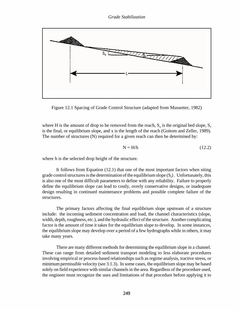
Grade Stabilization
249249
Figure 12.1 Spacing of Grade Control Structure (adapted from Mussetter, 1982)
where H is the amount of drop to be removed from the reach, So is the original bed slope, Sf
is the final, or equilibrium slope, and x is the length of the reach (Goitom and Zeller, 1989).The number of structures (N) required for a given reach can then be determined by:
N = H/h (12.2)
where h is the selected drop height of the structure.
It follows from Equation (12.1) that one of the most important factors when sitinggrade control structures is the determination of the equilibrium slope (Sf) . Unfortunately, thisis also one of the most difficult parameters to define with any reliability. Failure to properlydefine the equilibrium slope can lead to costly, overly conservative designs, or inadequatedesign resulting in continued maintenance problems and possible complete failure of thestructures.
The primary factors affecting the final equilibrium slope upstream of a structureinclude: the incoming sediment concentration and load, the channel characteristics (slope,width, depth, roughness, etc.), and the hydraulic effect of the structure. Another complicatingfactor is the amount of time it takes for the equilibrium slope to develop. In some instances,the equilibrium slope may develop over a period of a few hydrographs while in others, it maytake many years.
There are many different methods for determining the equilibrium slope in a channel.These can range from detailed sediment transport modeling to less elaborate proceduresinvolving empirical or process-based relationships such as regime analysis, tractive stress, orminimum permissible velocity (see 3.1.3). In some cases, the equilibrium slope may be basedsolely on field experience with similar channels in the area. Regardless of the procedure used,the engineer must recognize the uses and limitations of that procedure before applying it to
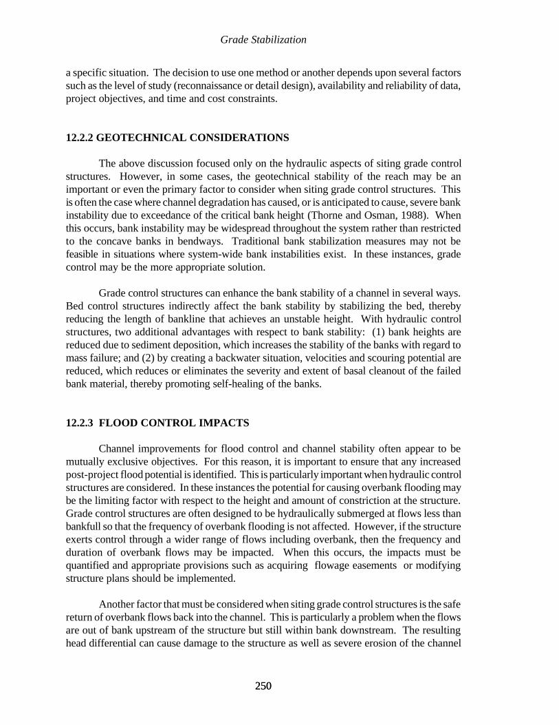
Grade Stabilization
250250
a specific situation. The decision to use one method or another depends upon several factorssuch as the level of study (reconnaissance or detail design), availability and reliability of data,project objectives, and time and cost constraints.
12.2.2 GEOTECHNICAL CONSIDERATIONS
The above discussion focused only on the hydraulic aspects of siting grade controlstructures. However, in some cases, the geotechnical stability of the reach may be animportant or even the primary factor to consider when siting grade control structures. Thisis often the case where channel degradation has caused, or is anticipated to cause, severe bankinstability due to exceedance of the critical bank height (Thorne and Osman, 1988). Whenthis occurs, bank instability may be widespread throughout the system rather than restrictedto the concave banks in bendways. Traditional bank stabilization measures may not befeasible in situations where system-wide bank instabilities exist. In these instances, gradecontrol may be the more appropriate solution.
Grade control structures can enhance the bank stability of a channel in several ways.Bed control structures indirectly affect the bank stability by stabilizing the bed, therebyreducing the length of bankline that achieves an unstable height. With hydraulic controlstructures, two additional advantages with respect to bank stability: (1) bank heights arereduced due to sediment deposition, which increases the stability of the banks with regard tomass failure; and (2) by creating a backwater situation, velocities and scouring potential arereduced, which reduces or eliminates the severity and extent of basal cleanout of the failedbank material, thereby promoting self-healing of the banks.
12.2.3 FLOOD CONTROL IMPACTS
Channel improvements for flood control and channel stability often appear to bemutually exclusive objectives. For this reason, it is important to ensure that any increasedpost-project flood potential is identified. This is particularly important when hydraulic controlstructures are considered. In these instances the potential for causing overbank flooding maybe the limiting factor with respect to the height and amount of constriction at the structure.Grade control structures are often designed to be hydraulically submerged at flows less thanbankfull so that the frequency of overbank flooding is not affected. However, if the structureexerts control through a wider range of flows including overbank, then the frequency andduration of overbank flows may be impacted. When this occurs, the impacts must bequantified and appropriate provisions such as acquiring flowage easements or modifyingstructure plans should be implemented.
Another factor that must be considered when siting grade control structures is the safereturn of overbank flows back into the channel. This is particularly a problem when the flowsare out of bank upstream of the structure but still within bank downstream. The resultinghead differential can cause damage to the structure as well as severe erosion of the channel
Grade Stabilization
251251
banks depending upon where the flow re-enters the channel. Some means of controlling theoverbank return flows must be incorporated into the structure design. One method is simplyto design the structure to be submerged below the top bank elevation, thereby reducing thepotential for a head differential to develop across the structure during overbank flows. If thestructures exerts hydraulic control throughout a wider range of flows including overbank,then a more direct means of controlling the overbank return flows must be provided. Onemethod is to ensure that all flows pass only through the structure. This may be accomplishedby building an earthen dike or berm extending from the structure to the valley walls whichprevents any overbank flows from passing around the structure (Forsythe, 1985). Anothermeans of controlling overbank flows is to provide an auxiliary high flow structure which willpass the overbank flows to a specified downstream location where the flows can re-enter thechannel without causing significant damage (Hite and Pickering, 1982).
12.2.4 ENVIRONMENTAL CONSIDERATIONS
The key phrase in water resources management today is “sustainable development”which simply means that projects must work in harmony with the natural system to meet theneeds of the present without compromising the ability of future generations to meet theirneeds. Engineers and geomorphologist are responding to this challenge by trying to developnew and innovative methods for incorporating environmental features into channel projects.The final siting of a grade control structure is often modified to minimize adverseenvironmental impacts to the system.
Grade control structures can provide direct environmental benefits to a stream.Cooper and Knight (1987) conducted a study of fisheries resources below natural scour holesand man-made pools below grade control structures in north Mississippi. They concludedthat although there was greater species diversity in the natural pools, there was increasedgrowth of game fish and a larger percentage of harvestable-size fish in the man-made pools.They also observed that the man-made pools provided greater stability of reproductivehabitat. Shields et al. (1990) reported that the physical aquatic habitat diversity was higherin stabilized reaches of Twentymile Creek, Mississippi than in reaches without grade controlstructures. They attributed the higher diversity values to the scour holes and low-flowchannels created by the grade control structures. The use of grade control structures asenvironmental features is not limited to the low-gradient sand bed streams of the southeasternUnited States. Jackson (1974) documented the use of gabion grade control structures tostabilize a high-gradient trout stream in New York. She observed that following constructionof a series of bed sills, there was a significant increase in the density of trout. The increase introut density was attributed to the accumulation of gravel between the sills which improvedthe spawning habitat for various species of trout.
Perhaps the most serious negative environmental impact of grade control structuresis the obstruction to fish passage. In some cases, particularly when drop heights are small, fishare able to migrate upstream past a structure during high flows (Cooper and Knight, 1987).However, in situations where structures are impassable, and where the migration of fish is an

Grade Stabilization
252252
important concern, openings, fish ladders, or other passageways must be incorporated intothe design of the structure to address the fish movement problems (Nunnally and Shields,1985). The various methods of accomplishing fish movement through structures are notdiscussed here. Interested readers are referred to Nunnally and Shields (1985), Clay (1961),and Smith (1985) for a more detailed discussion.
The environmental aspects of the project must be an integral component of the designprocess when siting grade control structures. A detailed study of all environmental featuresin the project area should be conducted early in the design process. This will allow thesefactors to be incorporated into the initial plan rather than having to make costly and often lessenvironmentally effective last minute modifications to the final design. Unfortunately, thereis very little published guidance concerning the incorporation of environmental features intothe design of grade control structures. One source of useful information can be found in thefollowing technical reports published by the Environmental Laboratory of the Corps ofEngineers, WES (Shields and Palermo, 1982; Henderson and Shields, 1984; and Nunnally andShields, 1985).
12.2.5 EXISTING STRUCTURES
Bed degradation can cause significant damage to bridges, culverts, pipelines, utilitylines, and other structures along the channel perimeter. Grade control structures can preventthis degradation and thereby provide protection to these structures. For this reason, it isimportant to locate all potentially impacted structures when siting grade control structures.The final siting should be modified, as needed, within project restraints, to ensure protectionof existing structures.
It must also be recognized that grade control structures can have adverse as well asbeneficial effects on existing structures. This is a concern upstream of hydraulic controlstructures due to the potential for increased stages and sediment deposition. In theseinstances, the possibility of submerging upstream structures such as water intakes or drainagestructures may become a deciding factor in the siting of grade control structures.
Whenever possible, the engineer should take advantage of any existing structureswhich may already be providing some measure of grade control. This usually involvesculverts or other structures that provide a non-erodible surface across the streambed.Unfortunately, these structures are usually not initially designed to accommodate anysignificant bed lowering and, therefore, can not be relied on to provide long-term gradecontrol. However, it may be possible to modify these structures to protect against theanticipated degradation. These modifications may be accomplished by simply adding someadditional riprap with launching capability at the downstream end of the structure. In othersituations, more elaborate modifications such as providing a sheet pile cutoff wall or energydissipation devices may be required. Damage to and failure of bridges is the naturalconsequence of channel degradation. Consequently, it is not uncommon in a channelstabilization project to have several bridges that are in need of repair or replacement. In
Grade Stabilization
253253
MAIN DITCH - MODIFIED DROP STRUCTURE AND ROAD CROSSING
Figure 12.2 Combination Grade Control Structure and Road Crossing (adapted fromU.S. Soil Conservation Service, 1976)
these situations it is often advantageous to integrate the grade control structure into theplanned improvements at the bridge. If the bridge is not in immediate danger of failing andonly needs some additional erosion protection, the grade control structure can be built at orimmediately downstream of the bridge with the riprap from the structure tied into the bridgefor protection. If the bridge is to be replaced, then it may be possible to construct the gradecontrol structure concurrently with the road crossing (Figure 12.2).
12.2.6 LOCAL SITE CONDITIONS
When planning grade control structures, the final siting is often adjusted toaccommodate local site conditions, such as the planform of the stream or local drainage. A
stable upstream alignment that provides a straight approach into the structure is critical.Since failure to stabilize the upstream approach may lead to excessive scour and possibleflanking of the structure, it is desirable to locate the structure in a straight reach. If this isnot possible (as in the case in a very sinuous channel), it may be necessary to realign thechannel to provide an adequate approach. Stabilization of the realigned channel may berequired to ensure that the approach is maintained. Even if the structure is built in a straightreach, the possibility of upstream meanders migrating into the structure must be considered.In this case, the upstream meanders should be stabilized prior to, or concurrent with, theconstruction of the grade control structure.
Grade Stabilization
254254
Local inflows from tributaries, field drains, road side ditches, or other sources oftenplay an important part in the siting of grade control structures. Failure to provide protectionfrom local drainage can result in severe damage to a structure (U.S. Army Corps ofEngineers, 1981). During the initial siting of the structure, all local drainage should beidentified. Ideally, the structure should be located to avoid local drainage problems.However, there may be some situations where this is not possible. In these instances, thelocal drainage should either be re-directed away from the structure or incorporated into thestructure design in such a manner that there will be no damage to the structure.
12.2.7 DOWNSTREAM CHANNEL RESPONSE
Since grade control structures affect the sediment delivery to downstream reaches, itis necessary to consider the potential impacts to the downstream channel when grade controlstructures are planned. Bed control structures reduce the downstream sediment loading bypreventing the erosion of the bed and banks, while hydraulic control structures have the addedeffect of trapping sediments. The ultimate response of the channel to the reduction insediment supply will vary from site to site. In some instances the effects of grade controlstructures on sediment loading may be so small that downstream degradational problems maynot be encountered. However, in some situations such as when a series of hydraulic controlstructures is planned, the cumulative effects of sediment trapping may become significant.In these instances, it may be necessary to modify the plan to reduce the amount of sedimentbeing trapped or to consider placing additional grade control structures in the downstreamreach to protect against the induced degradation.
12.2.8 GEOLOGIC CONTROLS
Geologic controls often provide grade control in a similar manner to a bed controlstructure. In some cases a grade control structure can actually be eliminated from the planif an existing geologic control can be utilized to provide a similar level of bed stability.However, caution must always be used when relying on geologic outcrops to provide long-term grade control. In situations where geologic controls are to be used as permanent gradecontrol structures, a detailed geotechnical investigation of the outcrop is needed to determineits vertical and lateral extent. This is necessary to ensure that the outcrop will neither beeroded, undermined or flanked during the project life.
Grade Stabilization
255255
12.2.9 EFFECTS ON TRIBUTARIES
The effect of main stem structures on tributaries should be considered when sitinggrade control structures. As degradation on a main stem channel migrates upstream it maybranch up into the tributaries. Therefore, the siting of grade control structures should considereffects on the tributaries. If possible, main stem structures should be placed downstream oftributary confluences. This will allow one structure to provide grade control to both the mainstem and the tributary. This is generally a more cost effective procedure than having separatestructures on each channel.
12.2.10 SUMMARY
The above discussion illustrates that the siting of grade control structures is not simplya hydraulic exercise. Rather, there are many other factors that must be included in the designprocess. For any specific situation, some or all of the factors discussed in this section maybe critical elements in the final siting of grade control structures. It is recognized that thisdoes not represent an all inclusive list since there may be other factors not discussed here thatmay be locally important. For example, in some cases, maintenance requirements, debrispassage, ice conditions, or safety considerations may be controlling factors. Consequently,there is no definitive “cookbook” procedure for siting grade control structures that can beapplied universally. Rather, each situation must be assessed on an individual basis.
12.3 TYPES OF GRADE CONTROL STRUCTURES
There are certain features which are common to most grade control structures. Theseinclude a control section for accomplishing the grade change, a section for energy dissipation,and protection of the upstream and downstream approaches. However, there is considerablevariation in the design of these features. For example, a grade control structure may beconstructed of riprap, concrete, sheet piling, treated lumber, soil cement, gabions, compactedearth fill, or other locally available material. Also, the shape (sloping or vertical drop) anddimensions of the structure can vary significantly, as can the various appurtenances (baffleplates, end sills, etc.). The applicability of a particular type of structure to any given situationdepends upon a number of factors such as: hydrologic conditions, sediment size and loading,channel morphology, floodplain and valley characteristics, availability of constructionmaterials, project objectives, and time and funding constraints. The successful use of aparticular type of structure in one situation does not necessarily ensure it will be effective inanother. Some of the more common types of grade control structures used in a variety ofsituations are discussed in the following sections. For more information on various structuredesigns, the reader is referred to Neilson et al. (1991), which provides a comprehensiveinternational literature review on grade control structures with an annotated bibliography.
Grade Stabilization
256256
12.3.1 SIMPLE BED CONTROL STRUCTURES
Perhaps the simplest form of a grade control structure consists of dumping rock,concrete rubble, or some other locally available non-erodible material across the channel toform a hard point. These structures are often referred to as rock sills, or bed sills. These typeof structures are generally most effective in small stream applications and where the dropheights are generally less than about 2 to 3 feet. A series of rock sills, each creating a headloss of about two feet was used successfully on the Gering Drain in Nebraska (Stufft, 1965).The design concept presented by Whitaker and Jaggi (1986) for stabilizing the streambed witha series of rock sills is shown in Figure 12.3. The sills in Figure 12.3 are classic bed controlstructures which are simply acting as hard points to resist the erosion of the streambed.
Construction of bed sills is sometimes accomplished by simply placing the rock alongthe streambed to act as a hard point to resist the erosive forces of the degradational zone. Inother situations, a trench may be excavated across the streambed and then filled with rock.A critical component in the design of these structures is ensuring that there is sufficientvolume of non-erodible material to resist the general bed degradation, as well as the localscour at the structure. This is illustrated in Figures 12.4a and 12.4b which shows a riprapgrade control structure designed to resist both the general bed degradation of the approachingknickpoint as well as any local scour that may be generated at the structure. In this instance,the riprap section must have sufficient mass to launch with an acceptable thickness to theanticipated scour hole depth.
12.3.2 STRUCTURES WITH WATER CUTOFF
One problem often encountered with the above structures is the displacement of rock(or rubble, etc.) due to the seepage flow around and beneath the structure. This is particularlya problem when the bed of the channel is composed primarily of pervious material. Thisproblem can be eliminated by constructing a water barrier at the structure. One type of waterbarrier consists of simply placing a trench of impervious clay fill upstream of the weir crest.This type of water barrier is illustrated in Figures 12.5a and 12.5b. One problem with thistype of barrier is its longevity due to susceptibility to erosion. This problem can be avoidedby using concrete or sheet piling for the cutoff wall. The conceptual design of a riprap gradecontrol structure with a sheet pile cutoff wall is shown in Figures 12.6a and 12.6b. In the caseof the sloping riprap drop structures used by the Denver Urban Drainage and Flood ControlDistrict, an impervious clay fill is used in conjunction with a lateral cutoff wall (McLaughlinWater Engineers, Ltd., 1986). This design is illustrated in Figure 12.7.

Grade Stabilization
257257
ORIGINAL BED
STABLE CHANNELSLOPE
BLOCK SILLS
STABLE REACH
(a)
STABLE CHANNELSLOPE
(b)
(c)
Figure 12.3 Channel Stabilization with Rock Sills (adapted from Whitaker and Jaggi,1986)
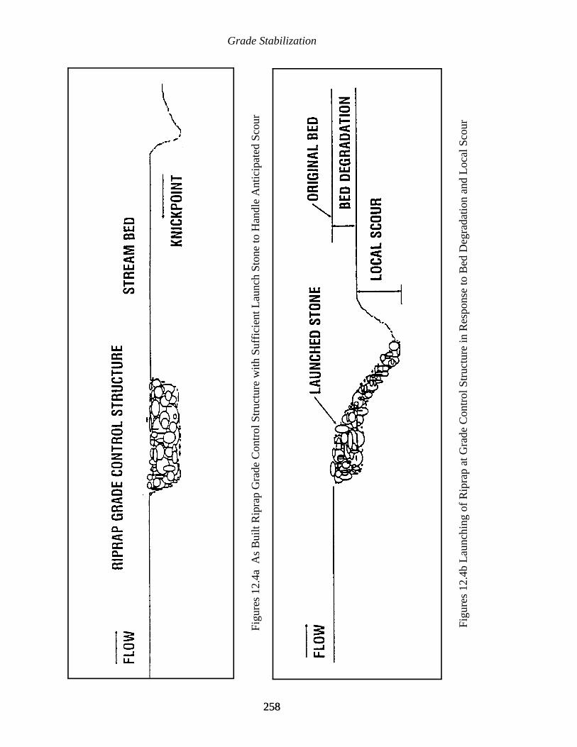
Grade Stabilization
258258
Figu
res
12.4
a A
s B
uilt
Rip
rap
Gra
de C
ontr
ol S
truc
ture
with
Suf
fici
ent L
aunc
h St
one
to H
andl
e A
ntic
ipat
ed S
cour
Figu
res
12.4
b L
aunc
hing
of
Rip
rap
at G
rade
Con
trol
Str
uctu
re in
Res
pons
e to
Bed
Deg
rada
tion
and
Loc
al S
cour
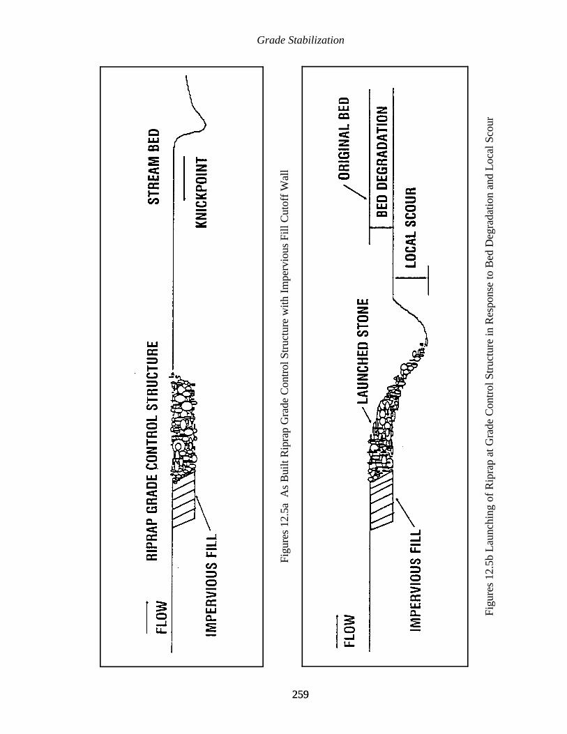
Grade Stabilization
259259
Figu
res
12.5
a A
s B
uilt
Rip
rap
Gra
de C
ontr
ol S
truc
ture
with
Im
perv
ious
Fill
Cut
off
Wal
l
Figu
res
12.5
b L
aunc
hing
of
Rip
rap
at G
rade
Con
trol
Str
uctu
re in
Res
pons
e to
Bed
Deg
rada
tion
and
Loc
al S
cour
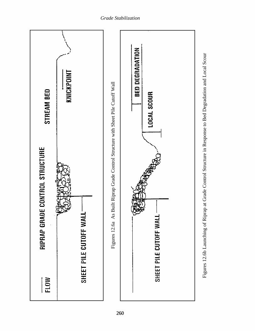
Grade Stabilization
260260
Figu
res
12.6
a A
s B
uilt
Rip
rap
Gra
de C
ontr
ol S
truc
ture
with
She
et P
ile C
utof
f W
all
Figu
res
12.6
b L
aunc
hing
of
Rip
rap
at G
rade
Con
trol
Str
uctu
re in
Res
pons
e to
Bed
Deg
rada
tion
and
Loc
al S
cour
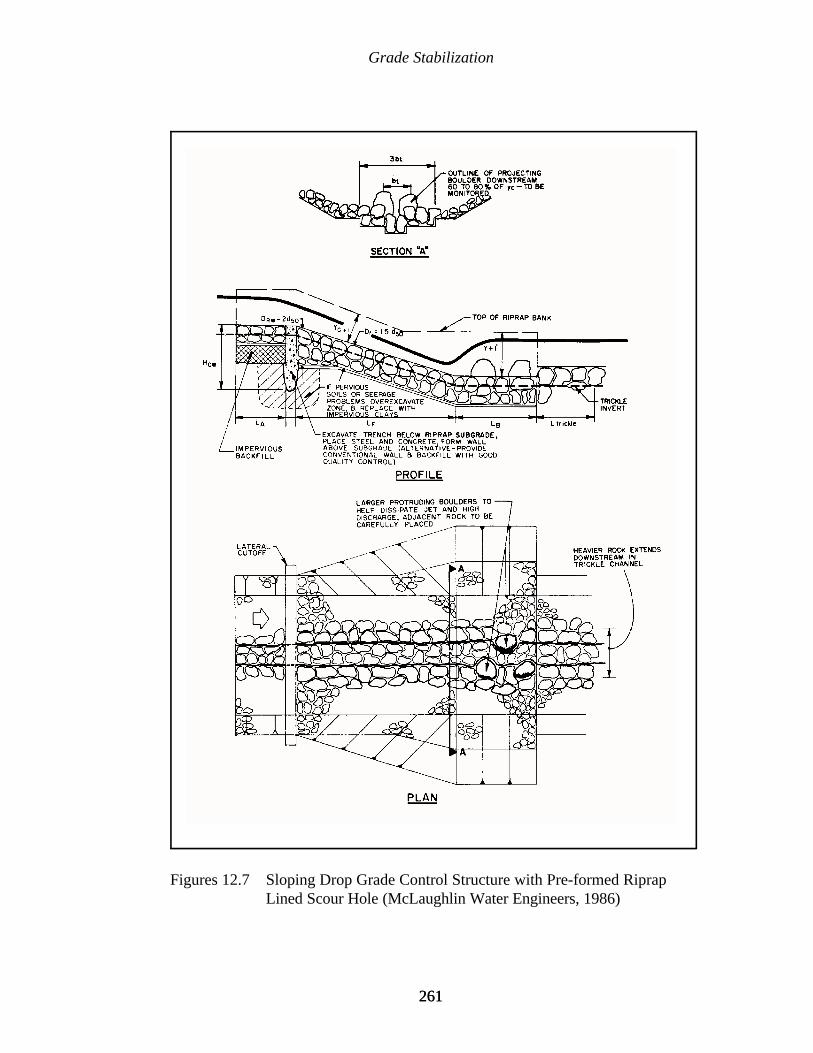
Grade Stabilization
261261
Figures 12.7 Sloping Drop Grade Control Structure with Pre-formed RiprapLined Scour Hole (McLaughlin Water Engineers, 1986)
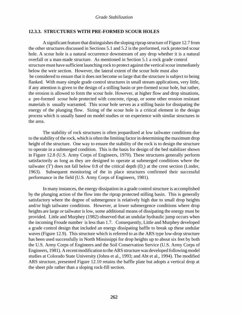
Grade Stabilization
262262
12.3.3. STRUCTURES WITH PRE-FORMED SCOUR HOLES
A significant feature that distinguishes the sloping riprap structure of Figure 12.7 fromthe other structures discussed in Sections 5.1 and 5.2 is the preformed, rock protected scourhole. A scour hole is a natural occurrence downstream of any drop whether it is a naturaloverfall or a man-made structure. As mentioned in Section 5.1 a rock grade controlstructure must have sufficient launching rock to protect against the vertical scour immediatelybelow the weir section. However, the lateral extent of the scour hole must also be considered to ensure that it does not become so large that the structure is subject to beingflanked. With many simple grade control structures in small stream applications, very little,if any attention is given to the design of a stilling basin or pre-formed scour hole, but rather,the erosion is allowed to form the scour hole. However, at higher flow and drop situations,a pre-formed scour hole protected with concrete, riprap, or some other erosion resistantmaterials is usually warranted. This scour hole serves as a stilling basin for dissipating theenergy of the plunging flow. Sizing of the scour hole is a critical element in the designprocess which is usually based on model studies or on experience with similar structures inthe area.
The stability of rock structures is often jeopardized at low tailwater conditions dueto the stability of the rock, which is often the limiting factor in determining the maximum dropheight of the structure. One way to ensure the stability of the rock is to design the structureto operate in a submerged condition. This is the basis for design of the bed stabilizer shownin Figure 12.8 (U.S. Army Corps of Engineers, 1970). These structures generally performsatisfactorily as long as they are designed to operate at submerged conditions where thetailwater (T') does not fall below 0.8 of the critical depth (Dc) at the crest section (Linder,1963). Subsequent monitoring of the in place structures confirmed their successfulperformance in the field (U.S. Army Corps of Engineers, 1981).
In many instances, the energy dissipation in a grade control structure is accomplishedby the plunging action of the flow into the riprap protected stilling basin. This is generallysatisfactory where the degree of submergence is relatively high due to small drop heightsand/or high tailwater conditions. However, at lower submergence conditions where dropheights are large or tailwater is low, some additional means of dissipating the energy must beprovided. Little and Murphey (1982) observed that an undular hydraulic jump occurs whenthe incoming Froude number is less than 1.7. Consequently, Little and Murphey developeda grade control design that included an energy dissipating baffle to break up these undularwaves (Figure 12.9). This structure which is referred to as the ARS type low-drop structurehas been used successfully in North Mississippi for drop heights up to about six feet by boththe U.S. Army Corps of Engineers and the Soil Conservation Service (U.S. Army Corps ofEngineers, 1981). A recent modification to the ARS structure was developed following modelstudies at Colorado State University (Johns et al., 1993; and Abt et al., 1994). The modifiedARS structure, presented Figure 12.10 retains the baffle plate but adopts a vertical drop atthe sheet pile rather than a sloping rock-fill section.
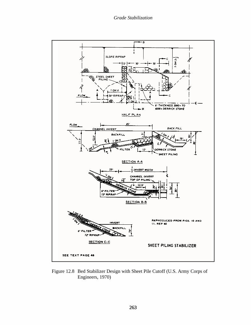
Grade Stabilization
263263
Figure 12.8 Bed Stabilizer Design with Sheet Pile Cutoff (U.S. Army Corps ofEngineers, 1970)

Grade Stabilization
264264
Figure 12.9 ARS-Type Grade Control Structure with Pre-formed Riprap Lined StillingBasin and Baffle Plate (adapted from Little and Murphey, 1982)
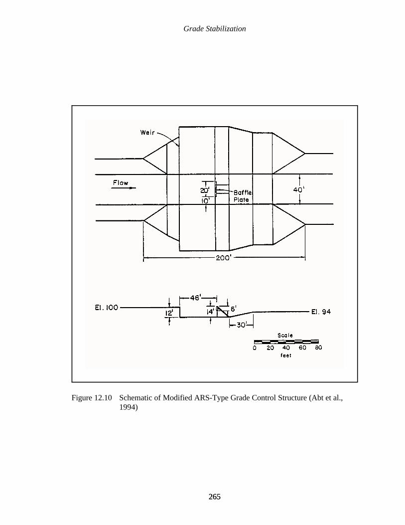
Grade Stabilization
265265
Figure 12.10 Schematic of Modified ARS-Type Grade Control Structure (Abt et al.,1994)
Grade Stabilization
266266
12.3.4 CONCRETE DROP STRUCTURES
In many situations where the discharges and/or drop heights are large, grade controlstructures are normally constructed of concrete. There are many different designs for concretegrade control structures. The two discussed herein are the CIT and the St. Anthony Falls(SAF) structures. Both of these structures were utilized on the Gering Drain project inNebraska, where the decision to use one or the other was based on the flow and channelconditions (Stufft, 1965). Where the discharges were large and the channel depth wasrelatively shallow, the CIT type of drop structure was utilized. The CIT structure is generallyapplicable to low-drop situations where the ratio of the drop height to critical depth is lessthan one; however, for the Gering Drain project this ratio was extended up to 1.2. Theoriginal design of this structure was based on criteria developed by Vanoni and Pollack(1959). The structure was then modified by model studies at the WES in Vicksburg,Mississippi, and is shown in Figure 12.11, (Murphy, 1967). Where the channel was relativelydeep and the discharges smaller, the SAF drop structure was used. This design wasdeveloped from model studies at the SAF Hydraulic Laboratory for the U.S. SoilConservation Service (Blaisdell, 1948). This structure is shown in Figure 12.12. The SAFstructure is capable of functioning in flow situations where the drop height to critical depthratio is greater than one and can provide effective energy dissipation within a Froude numberrange of 1.7 to 17. Both the CIT and the SAF drop structures have performed satisfactorilyon the Gering Drain for over 25 years.
12.3.5 CHANNEL LININGS
Grade control can also be accomplished by lining the channel bed with a non-erodiblematerial. These structures are designed to ensure that the drop is accomplished over aspecified reach of the channel which has been lined with riprap or some other non-erodiblematerial. Rock riprap gradient control structures have been used by the U.S. SoilConservation Service for several years (U.S. Soil Conservation Service, 1976). Thesestructures are designed to flow in the subcritical regime with a constant specific energy at thedesign discharge which is equal to the specific energy of flow immediately upstream of thestructure (Myers, 1982). Although these structures have generally been successful, there havebeen some associated local scour problems. This precipitated a series of model studies at theWES to correct these problems and to develop a design methodology for these structures(Tate, 1988; and Tate, 1991). A plan and profile drawing of the improved structure is shownin Figure 12.13.
12.3.6 ALTERNATIVE CONSTRUCTION MATERIALS
While riprap and concrete may be the most commonly used construction materials forgrade control structures, many situations where cost or availability of materials may promptthe engineer to consider other alternatives. Gabion grade control structures are often
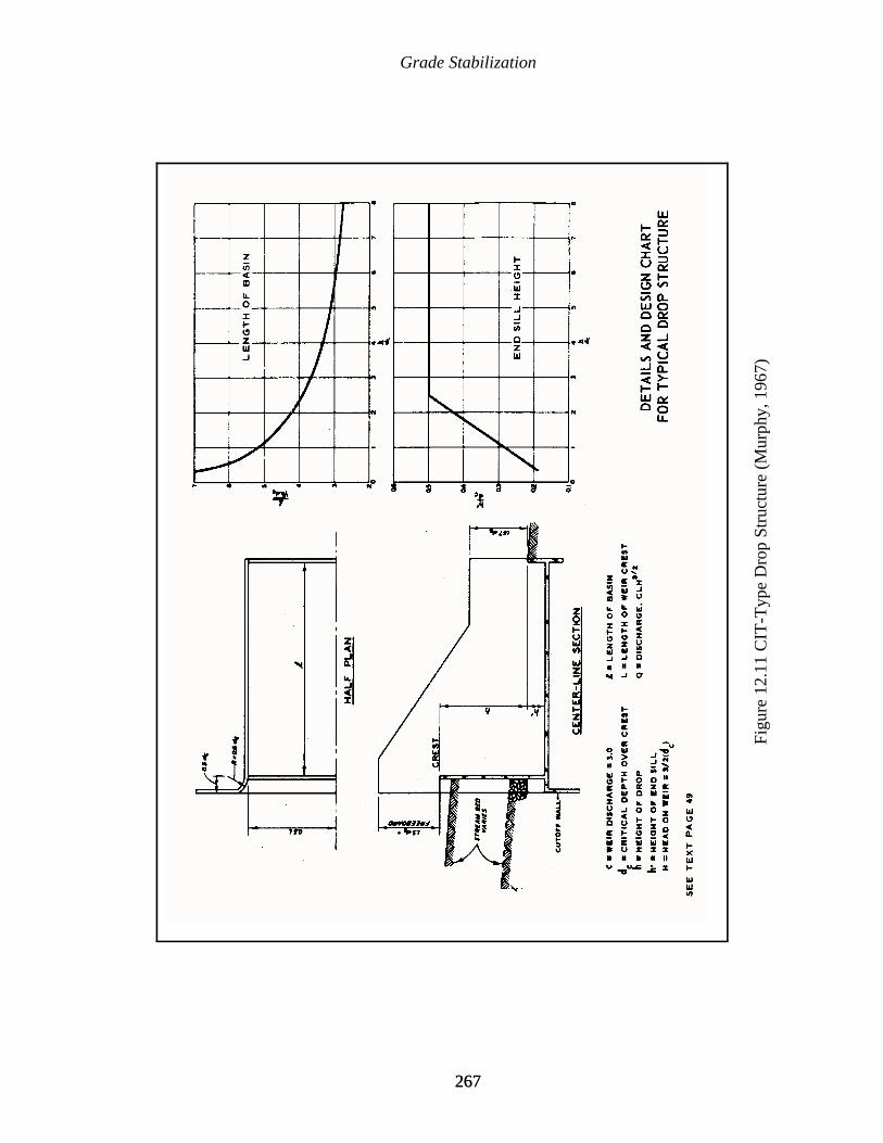
Grade Stabilization
267267
Figu
re 1
2.11
CIT
-Typ
e D
rop
Stru
ctur
e (M
urph
y, 1
967)

Grade Stabilization
268268
Figure 12.12 St. Anthony Falls (SAF) Type Drop Structure (Blaisdell, 1948)
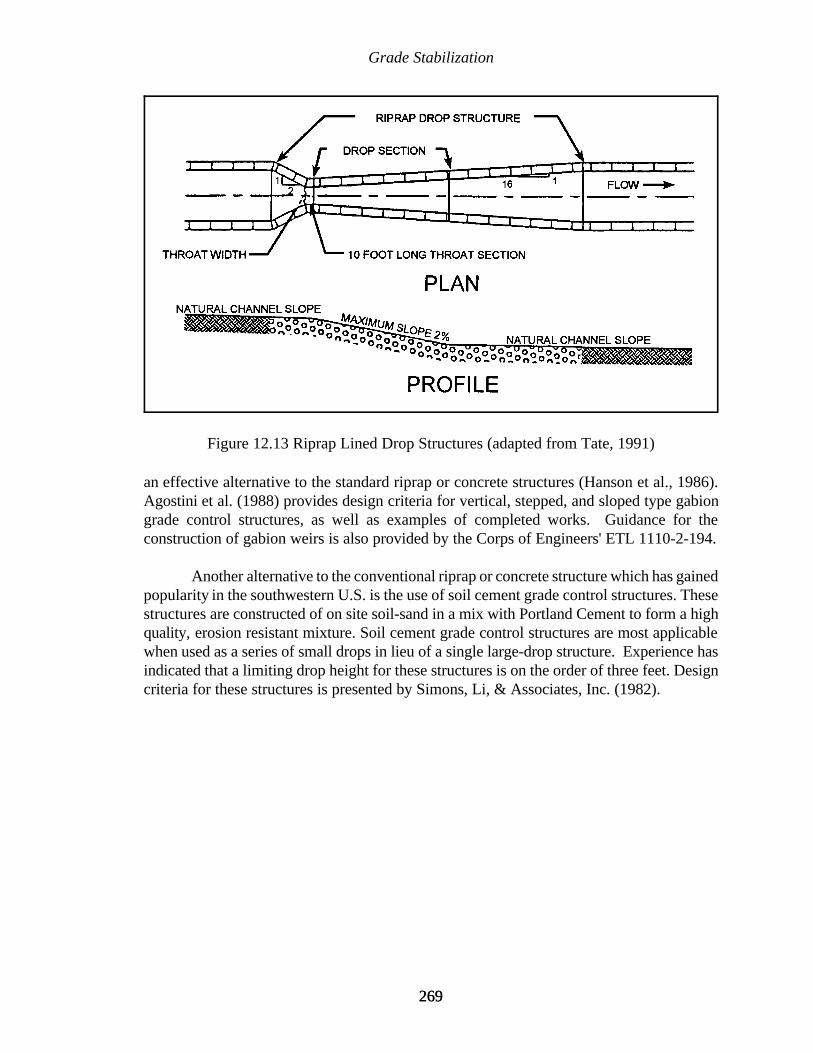
Grade Stabilization
269269
Figure 12.13 Riprap Lined Drop Structures (adapted from Tate, 1991)
an effective alternative to the standard riprap or concrete structures (Hanson et al., 1986).Agostini et al. (1988) provides design criteria for vertical, stepped, and sloped type gabiongrade control structures, as well as examples of completed works. Guidance for theconstruction of gabion weirs is also provided by the Corps of Engineers' ETL 1110-2-194.
Another alternative to the conventional riprap or concrete structure which has gainedpopularity in the southwestern U.S. is the use of soil cement grade control structures. Thesestructures are constructed of on site soil-sand in a mix with Portland Cement to form a highquality, erosion resistant mixture. Soil cement grade control structures are most applicablewhen used as a series of small drops in lieu of a single large-drop structure. Experience hasindicated that a limiting drop height for these structures is on the order of three feet. Designcriteria for these structures is presented by Simons, Li, & Associates, Inc. (1982).

Grade Stabilization
270270

271271
CHAPTER 13
CLOSING
Streambank erosion causes great economic loss, loss of cultural resources,degradation of water quality, aquatic and riparian habitat, and numerous downstreamproblems. For example, wetlands are frequently ephemeral features in the natural landscape,which through geomorphic process will eventually fill and become drier. Acceleratedstreambank erosion in the basin upstream of a wetland decreases the biological productivityof the wetland and reduces the life of the wetland. Another example that is frequentlyexperienced is the loss of flood control capacity due to sedimentation, which is caused byaccelerated streambank erosion upstream.
Streambank erosion is recognized by the Environmental Protection Agency (EPA) asa major source of nonpoint pollution. The Water Quality Act of 1987, section 101, includesthe following policy statement: It is the national policy that programs for the control ofnonpoint sources of pollution be developed and implemented in an expeditious manner.Unfortunately, at this point, no nationally recognized set of design and performance criteriaexist to meet this mandate, nor is there a comprehensive manual that provides guidance forthe design and construction of the many different types of streambank protection measures.
This handbook has been developed as a reference to be used in stabilization trainingcourses to be taught by the Waterways Experiment Station (WES) in cooperation with theEPA. The topics presented in this handbook are:
C Fundamentals of fluvial geomorphology and channel process;
C Geomorphic assessment and analysis of the proposed project site and watershedsystem;
C General approach and principles of bank stabilization;
C Selection of site specific stabilization techniques to include surface armor, indirectmethods, and bioengineered methods;
C Design and techniques for implementing grade control for system stabilization;

Closing
272272
C Aspects of management and contracting for construction of stabilization methods;and
C Monitoring and maintenance of stabilization.
Stream bank stabilization is not a simple matter of sizing armor material large enoughto resist fluvial entrainment, placing the armor at locations of bank erosion, and moving tothe next eroding site. As we have attempted to emphasize throughout this document, acookbook approach to bank stabilization is the embodiment of the phrase, complex problemsoften have quick and simple wrong answers. Although this first attempt in developing abank stabilization handbook is in excess of 300 pages and requires a significant effort by theuser, we firmly believe that the effort to consider the full range of topics in a bank stabilizationdesign is worth the effort. Proper streambank stabilization is a complex problem withoutquick and simple answers.
This handbook will be used by persons of a wide diversity of experience andeducation, we would appreciate your comments and suggestions for enhancement of thedocument. Please contact:
Dr. David BiedenharnCEWES - CR-RUSACE, WES3909 Halls Ferry Rd.Vicksburg, MS 39180
273273
REFERENCES
Abt, S.R., Hamilton, G.B., Watson, C.C., and Smith, J.B. (1994). Riprap sizing for modifiedARS-type basin. Jl. of Hydraulic Engineering, ASCE, 120(2):260-267.
Allen, H.H., and Klimas, C.V. (1986). Reservoir shoreline revegetation guidelines. TechnicalReport E-86-13, U.S. Army Engineer Waterways Experiment Station, Vicksburg,MS.
Allen, H.H., and Leech, J. R. (1997) Bioengineering for streambank erosion control. TR EL-97-8, U.S. Army Corps of Engineers Waterways Experiment Station, Vicksburg, MS.
Allen, J.R.L. (1970). A quantitative model of grain size and sedimentary structures in lateraldeposits. Geological Jl., 7:129-146.
ASCE (1965) Channel stabilization of alluvial rivers. Jl. of the Waterways and HarborsDivision, 91, February.
ASCE (1975). Manual 54: Sedimentation Engineering, V.A. Vanoni (ed.), American Societyof Civil Engineers, New York.
ASCE (1977). Sedimentation Engineering. V.A. Vanoni (ed.), ASCE Task Committee forthe preparation of the Manual on Sedimentation of the Sedimentation Committee ofthe Hydraulics Division, New York, NY.
Amidon, R.E. (1947). Discussion of Model study of Brown Canyon debris barriers (by K.J.Bermel and R.L. Sanks). Transactions, ASCE, 112.
Andrews, E.D. (1986). Downstream effects of Flaming Gorge Reservoir on the Green River,Colorado and Utah. Geological Society of America Bulletin, 97:1012-1023.
Baird, D. C. and Klumpp, C. C. (1992). Study of groins on the middle Rio Grande. InHydraulic Engineering, M. Jennings and N.G. Bhowmik (eds.), Proceedings of WaterForum '92 in Baltimore, MD, American Society of Civil Engineers.
Bermel, K.J., and Sanks, R.L. (1947). Model study of Brown Canyon Debris Barrier.Transactions, ASCE, 112.

References
274274
Biedenharn, D.S. (1983). Channel response on the Little Tallahatchie River downstream ofSardis Dam. Proceedings of the Rivers 1983 Conference, ASCE, New Orleans, LA.
Biedenharn, D.S. (1995). Streambed degradation protection measures. Training Course onStreambank Erosion and Protection, U.S. Army Corps of Engineers, WaterwaysExperiment Station, Vicksburg, MS (unpublished).
Biedenharn, D.S., Little, Jr., C.D., and Thorne, C.R. (1990). Effects of low drop gradecontrol structure on bed and bank stability. Proceedings of the National Conferenceon Hydraulic Engineering, ASCE, San Diego, CA.
Biedenharn, D.S., Combs, P.G., Hill, G.J., Pinkand, C.F., and Pinkston, C.B. (1989).Relationship between channel migration and radius of curvature on the Red River.In Sediment Transport Modeling, S.Y. Wang (ed.), Proceedings of the InternationalSymposium.
Blaisdell, F.W. (1948). Development and hydraulic design, Saint Anthony Falls StillingBasin. Transactions, ASCE, 113(2342):483-561.
Blench, T. (1969). Mobile-Bed Fluviology. Edmonton, Alberta, Canada: The University ofAlberta Press, p. 28.
Boeters, R.E.A.M., Meesters, H.J.N., Schiereck, G.J., Simons, H.E.J., Stuip, J., Swanenberg,A.T.P., Verheij, H.J., and Verkade, G.J. (1994). Waterways with room for nature.Section I-4, 28th Congress of PIANC in Seville, Permanent International Associationof Navigational Congresses.
Bowie, A.J. (1995). Use of vegetation to stabilize eroding streambanks. ConservationResearch Report No. 43, U.S. Department of Agriculture, Agricultural ResearchService, Oxford, MS.
Brice, J.C. (1981). Stability of relocated stream channels. Report to Federal HighwaysAdministration, Report No. FHWA/RD-80/158, Washington, DC, 177 p.
Brice J.C. (1984). Planform properties of meandering rivers. In River Meandering, S.Y.Wang (ed.), New York, NY: ASCE, pp. 1-15.
Brookes, A. (1988). Channelized Rivers: Perspectives for Environmental Management.Chichester: John Wiley & Sons.
Brown, S.A. (1985). Design of spur-type streambank stabilization structures. FHWA/RD-84/101, Federal Highway Administration, McLean, VA.
California Department of Highways (1960). Bank and shore protection in California highwaypractice. State of California, Documents Section, Sacramento, 1970.

References
275275
Carlson, E.J. (1987). Drainage from sloping land using oblique drains. Denver, CO:Hydraulics Branch, Division of Research and Laboratory Services, Engineering andResearch Center, U. S. Dept. of the Interior, Bureau of Reclamation.
Carlson, E.J., and Dodge, R.A. (1963) Control of alluvial rivers by steel jetties. Transactions,ASCE, 128(IV):347-375.
Chow, V.T. (1959). Open Channel Hydraulics. New York, NY: McGraw-Hill BookCompany, Inc.
Clay, C.H. (1961). Design of fishways and other fish facilities. Department of Fisheries andOceans, Ottawa, Canada: Queen's Printer.
Clemens, S. (1944). Mark Twain’s Life on the Mississippi. New York, NY: The HeritagePress.
Collinson, J.D. (1978). Alluvial Sediments. In Sedimentary Environments and Faces, H.G.Reading (ed.), New York, NY: Elsevier.
Cooper, C.M., and Knight, S.S. (1987). Fisheries in man-made pools below grade controlstructures and in naturally occurring scour holes of unstable streams. Jl. of Soil andWater Conservation, 42:370-373.
Copeland, R.R. (1983). Bank protection techniques using spur dikes. MP HL-83-1, U.S.Army Corps of Engineers, Waterways Experiment Station, Vicksburg, MS.
Coppin, N.J., and Richards, I.G. (1990). Use of Vegetation in Civil Engineering. London:Butterworths.
Derrick, D.L. (1997a). Harland Creek bendway weir/willow post bank stabilization project.In Management of Landscapes Disturbed by Channel Incision, ConferenceProceedings, S.S.Y. Wang, E.J. Langendoen, and F.D. Shields (eds.), Center forComputational Hydroscience and Engineering, University of Mississippi, University,MS.
Derrick, D.L. (1997b). Twelve low-cost, innovative, landowner financed, streambankprotection demonstration projects. In Management of Landscapes Disturbed byChannel Incision, S.S.Y. Wang, E.J. Langendoen, and F.D. Shields (eds.), ConfenceProceedings, Center for Computational Hydroscience and Engineering, University ofMississippi, University, MS.
Derrick, D. L., Pokrefke, T. J. Jr., Boyd, M.B., Crutchfield, J.P., and Henderson, R.R.(1994). Design and development of bendway weirs for the Dogtooth Bend reach,Mississippi River. Technical Report HL-94-10, U.S. Army Corps of Engineers,Waterways Experiment Station, Vicksburg, MS.

References
276276
Dury, G.H. (1964). Principles of underfit streams. U.S. Geol. Surv. Prof. Paper 452-A,Washington, DC, 67 p.
Einstein, H.A. (1972). Final Remarks. In Sedimentation, H.W. Shen (ed.), Symposium toHonor Professor H. A. Einstein, Sedimentation Symposium, Berkeley, CA, pp. 27-7.
Elliott, D.O. (1932). The improvement of the Lower Mississippi River for flood control andnavigation. U.S. Army Corps of Engineers, Mississippi River Commission andWaterways Experiment Station, Vicksburg, MS.
Elliott, C.M., and Pokrefke, T.J. (1984). Channel stabilization in a straight river reach. InRiver Meandering, C.M. Elliott (ed), Proceedings of Rivers '83, ASCE, New York,NY.
Elliott, C. M., Rentschler, R.E., and Brooks, J.H. (1991). Response of Lower MississippiRiver low-flow stages. Proceedings of the Federal Interagency Conference onSedimentation, Las Vegas, NV.
Farabee, G.B. (1986). Fish species associated with revetted and natural main border habitatsin pool 24 of the upper Mississippi River. North American Jl. of FisheriesManagement, 6:504-508.
FHWA (1985). Design of spur-type streambank stabilization structures. U.S. Departmentof Transportation, Federal Highway Administration, Report No. FHWA/RD 84/101,McLean, VA.
Forsythe, P. (1985). Performance of a grade control structure system during extremefloods," American Society of Agricultural Engineers Winter Meeting, Chicago, IL.
Fortier, S., and Scobey, F.C. (1926). Permissible canal velocities. Trans. Am. Soc. Civ.Engrs., no. 1588:941-984.
Franco, J.J. (1967). Research for river regulation dike design. Jl. of the Waterways andHarbors Division, ASCE, New York, NY, 93(WW 3), August.
Franco, J.J. (1982). Summary report: model-prototype comparison study of dike systems,Mississippi River: Potamology investigations. Vicksburg, MS: U.S. Army EngineerWaterways Experiment Station.
Friedkin, J.F. (1945). A laboratory study of the meandering of alluvial rivers. Vicksburg,MS: U.S. Army Engineer Waterways Experiment Station.
References
277277
Funk, J.L., and Robinson, J.W. (1974). Changes in the channel of the lower Missouri Riverand effects on fish and wildlife. Aquatic Series No. 11, Missouri Department ofConservation, Jefferson City, MO.
Gagliano, S.M., and Howard, P.C. (1984). The neck cutoff oxbow lake cycle along theLower Mississippi River. In River Meandering, C.M. Elliott (ed.), Proceedings ofRivers '83, ASCE, pp. 147-158.
Garg, S.P. (1970). Use of vegetation and bamboos in river training works. Irrigation andPower, October, 459-470.
Goitom, T.G., and M.E. Zeller (1989). Design procedures for soil-cement grade controlstructures. Proceedings of the National Conference on Hydraulic Engineering, ASCE,New Orleans, LA.
Gray, D.H. and Leiser, A.T. (1982). Biotechnical Slope Protection and Erosion Control.New York, NY: Van Nostrand Reinhold Co.
Gray, D.H., and Sotir, R.B. (1996). Biotechnical and Soil Bioengineering SlopeStabilization. New York, NY: John Wiley, 378 p.
Gregory, K.J., Davis, R. J., and Downs, P. W. (1992). Identification of river channel changedue to urbanisation. Applied Geography, 12:299-318.
Hagerty, D.J. (1991a). Piping/sapping erosion, I: Basic considerations. HY, August, 991-1008.
Hagerty, D.J. (1991b). Piping/sapping erosion, II: Identification-diagnosis. HY, August,1009-1025.
Hanson, G.J., Lohnes, R.A., and Klaiber, F.W. (1986). Gabions used in stream grade-stabilization structures: a case study. Transp. Res. Rec., p. 35-42.
Harris, F.C. (1901). Effects of dams and like obstructions in silt-bearing streams.Engineering News, 46.
Hatch, Lt. Gen. H.J. (1990). Strategic direction for environmental engineering", 14 February1990 letter, HQUSACE, Washington, DC.
Hausler, von, E. (1976). Absturze und Stutzschwellen in Hydraulischer und KonstructiverBetrachtung Versuchsanstalt fur Wasserbau der Techischen Universitat Munchen,Oskar, v. Miller Institut, Nr. 32.
References
278278
Heede, B.H. (1960). A study of early gully-control structures in the Colorado Front Range.U.S. Department of Agriculture, Forest Service, Rocky Mountain Forest and RangeExperiment Station, Paper No. 55, Fort Collins, CO.
Heede, B. H., and Mulich, J.G. (1973). Functional relationships and a computer program forstructural gully control. Jl. of Environmental Management, 1.
Hemphill, R.W., and Bramley, M.E. (1989). Protection of river and canal banks, CIRIAWater engineering Report, London: Butterworths.
Henderson, J.E. (1986). Environmental designs for streambank protection projects. WaterResources Bulletin, American Water Resources Association.
Henderson, J.E., and Shields, F.D. (1984). Environmental features for streambank ProtectionProjects. Technical Report E-84-11, U.S. Army Corps of Engineers WaterwaysExperiment Station, CE, Vicksburg, MS.
Hite, J.W., and Pickering, G.A. (1982). South Fork Tillatoba Creek drop structures,Mississippi; hydraulic model investigation. Technical Report HL-82-22, U.S. ArmyCorps of Engineers Waterways Experiment Station, Vicksburg, MS.
Institute of Environmental Sciences, Miami (Ohio) University (1982). A Guide to the GeorgePalmiter River restoration techniques. Contributing Report 82-CR1, U.S.ArmyEngineer Institute for Water Resources, Ft. Belvoir, VA.
Jackson, T.H. (1935). Bank protection on Mississippi and Missouri Rivers, M.R.C. 250.9-35, U.S. Army Corps of Engineers.
Jackson B.J. (1974). Stream Bed Stabilization in Enfield Creek, New York. New York Fishand Game Jl., 21(1):32-46.
Jansen, P.Ph., van Bendegom, L., van den Berg, J., de Vries, M., and Zanen, A., (eds.)(1979). Principles of River Engineering: The Non-tidal Alluvial River, London, SanFrancisco, Melbourne: Pitman.
Johns, D.D., Abt, S.R., Watson, C.C., and Combs, P.G. (1993). Riprap sizing for ARS-typelow-drop stilling basins. Jl. of Hydraulic Engineering, ASCE, 119( 7):864-869.
Johnson, J.W., and Minaker, W.L. (1944). Movement and deposition of sediment in thevicinity of debris-barriers. Transactions, American Geophysical Union, Part VI.
Kaetz, G.A., and Rich, L.R. (1939). Report of surveys made to determine grade ofdeposition above silt and gravel barriers. Soil Conservation Service, UnpublishedReport, Albuquerque, New Mexico.

References
279279
Kennedy, R.G. (1895). The prevention of silting in irrigation canals. Proceedings of theInstitution of Civil Engineers, 119:281-290.
Klingeman, P.C., and Bradley, J.B. (1976). Willamette River Basin streambank stabilizationby natural means. U.S. Army Corps of Engineers, Portland District, Portland, OR.
Knighton, D. (1984). Fluvial Forms and Processes. London: Edward Arnold.
Lacey, G. (1931). Regime diagrams for the design of canals and distributaries. TechnicalPaper No. 1, United Provinces: P.W.D. Irrigation Branch.
Lane, E.W. (1953). Design of stable channels. Trans. Am. Soc. Civ. Engrs., 120:1234-1260.
Lane, E.W. (1955). The importance of fluvial morphology in hydraulic engineering. Proc.ASCE, 81(745):1-17.
Lane, E.W. (1957). A study of the shape of channels formed by natural streams flowing inerodible material, M.R.D. Sediment Series No. 9, U.S. Army Engineer Division,Missouri River, Corps Engineers, Omaha, NE.
Leopold, L.B., and Maddock, Jr., T. (1953). The hydraulic geometry of stream channels andsome physiographic implications, U.S. Geol. Surv. Prof. Paper 242, Washington, DC,57 p.
Leopold, L.B., and Wolman, M.G. (1957). River channel patterns: braided, meandering andstraight. U.S. Geol. Surv. Prof. Paper 282-B, Washington, DC.
Leopold, L.B., and Wolman, M.G. (1960). River meanders. Bulletin of the GeologicalSociety of America, 71, June.
Leopold, L.B., Wolman, M.G., and Miller, J.P. (1964). Fluvial Processes in Geomorphology.San Francisco, CA: W. H. Freeman and Co., 522 p.
Li, R.M., and Lagasse, P.F. (Eds.) (1983). D.B. Simons Symposium on Erosion andSedimentation. Colorado State University and Waterway, Port, Coastal and OceanDivision of the ASCE, Chelsea, MI: Bookcrafters, Inc.
Linder, W.M. (1963). Stabilization of Stream Beds with Sheet Piling and Rock Sills.Prepared for Federal Interagency Sedimentation Conference, Subcommittee onSedimentation, ICWR, Jackson, MS.
Little, W.C., and Murphey, J.B. (1982). Model study of low drop grade control structures.Jl. of the Hydraulic Division, ASCE, 108(HY10):1132-1146.
References
280280
Liu C. (1989). Problems in management of the Yellow River. Regulated Rivers 3(1-4):361-369, Chichester: John Wiley and Sons.
Logan, L.D., et al. (1979). Vegetation and mechanical systems for streambank erosioncontrol, guidelines for streambank erosion control along the banks of the MissouriRiver from Garrison Dam downstream to Bismarck, North Dakota. U.S. Army Corpsof Engineers, Omaha District; USDA Forest Service, Northern Region; and NorthDakota State Forest Service; Missoula, MT.
Mackin, J.H. (1948). Concept of the graded river. Geol. Soc. Am. Bull., 59:463-512.
Mallik, A.U., and Harun, R. (1993). Root-shoot characteristics of riparian plants in a floodcontrol channel: implications for bank stabilization. Ecological Engineering 2:149-158.
McLaughlin Water Engineers, Ltd. (1986). Evaluation of and design recommendations fordrop structures in the Denver Metropolitan Area. A Report Prepared for the DenverUrban Drainage and Flood Control District.
Mellema, W.J. (1987). Construction and maintenance of streambank protection methodsprojects", (unpublished), Training Course on Streambank Erosion and Protection,U.S. Army Corps of Engineers, Waterways Experiment Station, Vicksburg, MS.
Mellema, W.J. (1995). Selected indirect streambank protection methods (dikes).(unpublished), Training Course on Streambank Erosion and Protection, U.S. ArmyCorps of Engineers, Waterways Experiment Station, Vicksburg, MS.
Murphy, T.E. (1967). Drop structures for Gering Valley Project, Scottsbluff County,Nebraska, hydraulic model investigation. Technical Report No. 2-760, U.S. ArmyCorps of Engineers Waterways Experiment Station, Vicksburg, MS.
Mussetter, R.A. (1982). Equilibrium slopes above channel control structures. M.S. Thesis,Colorado State University, Civil Engineering Department, Fort Collins, CO.
Myers, Jr., C.T. (1982). Rock riprap gradient control structures. Proceedings of theConference Applying Research to Hydraulic Practice, ASCE, Jackson, MS.
Nanson, G.C., and Hickin, E. J. (1986). A statistical analysis of bank erosion and channelmigration in western Canada. Geological Society of American Bulletin, 97(4):497-504.
Neill, C.R., and Galay, V.J. (1967). Systematic evaluation of river regime, Jl. Waterways andHarbors Division, ASCE, 93 (WW1):25 -51.
References
281281
Neilson, F.M., Waller, T.N., and Kennedy, K.M. (1991). Annotated bibliography on gradecontrol structures. Miscellaneous Paper, HL-91-4, U.S. Army WaterwaysExperiment Station, CE, Vicksburg, MS.
Nunnally, N.R., and Shields, F.D. (1985). Incorporation of environmental features in floodcontrol channel projects. Technical Report E-85-3, U.S. Army WaterwaysExperiment Station, CE, Vicksburg, MS.
Odgaard, A.J., and Kennedy, J.F. (1982). Analysis of Sacramento River bend flows, anddevelopment of a new method for bank protection. IIHR Report No. 241, IowaInstitute of Hydraulic Research, University of Iowa, Iowa City, IA.
Odgaard, A.J., and Kennedy, J. F. (1983). River bend bank protection by submerged vanes.Journal of the Hydraulics Division, ASCE, 109(8):1161-1173.
Odgaard, A.J., and Mosconi, C.E. (1987). Streambank protection by submerged vanes. Jl.of the Hydraulics Division, ASCE, 113(4):520-536.
Osman, A.M., and Thorne, C.R. (1988). Riverbank stability analysis: Part I, Theory. Jl. ofHydraulic Engineering, ASCE, 114(2):125-150.
Parsons, D.A. (1960). Effects of flood flow on channel boundaries. Jl. of the HydraulicsDivision, ASCE, 86(HY4):21-34.
Petersen, M.S. (1986). River Engineering. Englewood Cliffs, NJ: Prentiss-Hall.
PIANC (1987). Guidelines for the design and construction of flexible revetmentsincorporating geotextiles for inland waterways. Supplement to Bulletin 57, PermanentInternational Association of Navigational Congresses, Brussels.
Pickett, E.B., and Brown, B.J. (1977). Guidelines for monitoring and reportingdemonstration projects. IR H-77-1, U.S. Army Corps of Engineers WaterwaysExperiment Station, Vicksburg, MS.
Portland Cement Association (1975a). Soil-cement slope protection for embankments:planning and design. Skokie, IL.
Portland Cement Association (1975b). Soil-cement slope protection for embankments:construction. Skokie, IL.
Pravdivets, Y.P., and Bramley, M.E. (1989). Stepped protection blocks for dam spillways.Water Power and Dam Construction, July.
Richards, K. (1982). Rivers. United Kingdom: Methuen, 358 p.
References
282282
Ritter, D.F. (1978). Process Geomorphology. Dubuque, IA: W.C. Brown Publishers.
Rosgen, D.L. (1994). A classification of natural rivers, Catena, 22:169-199.
Rosgen, D.L. (1996). Applied River Morphology. Pagosa Springs, CO: Wildland Hydrology,8 sections plus bibliography.
Rundquist, L.A. (1975). A Classification and Analysis of Natural Rivers. Ph.D.Dissertation, Civil Engineering, Colorado State University, Fort Collins, CO, 377p.
Schiechtl, H. (1980). Bioengineering for Land Reclamation and Conservation Canada:University of Alberta Press.
Schumm, S.A. (1960). The effect of sediment type on the shape and stratification of somemodern fluvial deposits, Am. J. Sci., 258:177-184.
Schumm, S.A. (1972). River Morphology. Stroudsburg, PA: Dowden, Hutchinson & Ross.
Schumm, S.A. (1977). The Fluvial System. New York, NY: John Wiley & Sons, Inc.
Schumm, S.A. (1981). Evolution and response of the fluvial system, sedimentologicimplications. Society of Economic Paleontologists and Mineralogists, Special PubNo. 1, pp. 19-29.
Schumm, S.A. (1984). Episodic behavior of sand bed rivers, final report. Water Engineeringand Technology, Inc., Fort Collins, CO, 61 p.
Schumm, S.A., and Lichty, R.W. (1965). Time, space and causality in geomorphology, Am.Jl. Sci., 263:110-119.
Schumm, S.A., and Meyer, D. F. (1979). Morphology of alluvial rivers of the Great Plains,Great Plains Agricultural Council Pub. 91, pp. 9-14.
Schumm, S.A., and Parker, R.S. (1973). Implications of complex response of drainagesystems for Quarternary alluvial stratigraphy, Nat. Phys. Sci., 243:99-100.
Schumm, S.A., Harvey, M.D., and Watson, C.C. (1984). Incised Channels: Morphology,Dynamics and Control. Littleton, CO: Water Resources Publications.
Schwab, G.O., Frevert, R.K., Edminster, T.W., and Barnes, K.K. (1981). Soil and WaterConservation Engineering. Third Edition, John Wiley and Sons.
References
283283
Seibert, P. (1968). Importance of natural vegetation for the protection of the banks ofstreams, rivers, and canals. Nature and Environment Series, Council of Europe, pp.35-67.
Shields, F.D. (1987). Management of cutoff meander bends. PhD Dissertation, ColoradoState University, Ann Arbor, MI: University Microfilm Inc..
Shields, F.D., and Abt, S.R. (1989). Sedimentation in cutoff meander bends and implicationsfor effective management. Regulated Rivers, Chichester: John Wiley & Sons,4(4):381-396.
Shields, F.D., Hoover, J.J., Nunnally, N.R., Kilgore, K.J., Schaefer, T.E., and Waller, T.N.(1990). Hydraulic and environmental effects of channel stabilization TwentymileCreek, Mississippi. Technical Report EL-90-14, U.S. Army Corps of EngineersWaterways Experiment Station, Vicksburg MS.
Shields, F.D., and Palermo, M.R. (1982). Assessment of Environmental Considerations inthe Design and Construction of Waterway Projects. Technical Report E-82-8, U.S.Army Waterways Experiment Station, CE, Vicksburg, MS.
Simons, D.B. (1957). Theory and design of stable channels in alluvial materials. Ph.D.Dissertation, Colorado State University, Fort Collins, CO.
Simons, D.B., and Albertson, M.L. (1963). Uniform water conveyance channels in alluvialmaterial. Trans. Am. Soc. Civ. Engrs., 128:65-167.
Simons, D.B., Chen, Y.H., Swenson, L. J. (1984). Hydraulic tests to develop design criteriafor the use of Reno mattresses. Colorado State University, Ft. Collins, CO.
Simon, A., and Hupp, C.R. (1992). Geomorphic and vegetative recovery processes alongmodified stream channels of west Tennessee. U.S. Geological Survey Open FileReport, 91-502, Nashville, TN.
Simons, D.B. and Sentürk, F. (1992). Sediment Transport Technology. Littleton, CO: WaterResources Publications, 897 p.
Simons, Li, and Associates (1982). Engineering analysis of fluvial systems, Fort Collins, CO.
Smardon, R.C. (1983). The Future of Wetlands: Assessing Visual-Cultural Values. Totowa,NJ: Allanheld, Osmun.
Smith, C.D. (1985). Hydraulic Structures. Saskatoon, Canada: University of SaskatchewanPrinting Services.
References
284284
Stufft, W.A. (1965). Erosion control for Gering Valley," American Society of CivilEngineers, Hydraulics Division Conference, Tucson, AZ.
Sugio, S., Hashino, M., and Sasaki, E. (1973). Debris slopes above sand barriers.International Symposium on River Mechanics, Bangkok, Thailand.
Tate, Jr., C.H. (1988). Muddy creek grade control structures, Muddy Creek, Mississippi andTennessee. Technical Report HL-88-11, U.S. Army Waterways Experiment Station,CE, Vicksburg, MS.
Tate, Jr., C.H. (1991). Soil Conservation Service Low Drop Structure Model Study.Technical Report HL-91-13, U.S. Army Waterways Experiment Station, CE,Vicksburg MS.
Thomas, W.A., Copeland, R.R., Raphelt, N.K., and McComas, D.N. (1993). User’s manualfor the hydraulic design package for channels (SAM). Water Ex. Station, USACE.
Thorne, C.R. (1982). Processes and mechanisms of riverbank erosion. In Gravel BedRivers, R. D. Hey, J.C. Bathurst, and C. R. Thorne (eds.), United Kingdom: Wiley,pp. 227-271.
Thorne, C.R. (1993). Guidelines for the use of stream reconnaissance sheets in the field.Contract Report HL-93-2, U.S. Army Engineer Waterways Experiment Station,Vicksburg, MS, 91 p.
Thorne, C.R., Newson, M.D., and Hey, R. D. (1997). Applied Fluvial Geomorphology forRiver Engineering and Management. United Kingdom: Wiley (in press).
Thorne, C.R. and Osman, A.M. (1988). Riverbank stability analysis II: Applications," Jl. ofHydraulic Engineering, ASCE, 114(2):151-172.
United Nations (1953). River training and bank protection. Flood control series no. 4,United Nations, New York.
U.S. Army Coastal Engineering Research Center (1984). Shore Protection Manual.
U.S. Army Corps of Engineers (1980). Layout and Design of Shallow Draft Waterways.Engineering Manual 1110-2-1611,
U.S. Army Corps of Engineers (1981a). The Streambank Erosion Control Evaluation andDemonstration Act of 1974. Final Report to Congress, Appendix B - HydraulicResearch.
References
285285
U.S. Army Corps of Engineers (1981b). The Streambank Erosion Control Evaluation andDemonstration Act of 1974. Final Report to Congress, Appendix C - GeotechnicalResearch.
U.S. Army Corps of Engineers (1981c). Streambank Erosion Control and DemonstrationProject (Section 32). Final Report to Congress, Appendix F - Yazoo River BasinDemonstration Projects.
U.S. Army Corps of Engineers (1981d) Streambank Erosion Control and DemonstrationProject (Section 32), Final Report to Congress, Appendix H - Evaluation of ExistingProjects.
U.S. Army Corps of Engineers (1984). Lower Mississippi Valley Division, Vicksburg, MS,12 July 1984 memo on revetments from Chief, River Engineering Branch to Chief,Engineering Division.
U.S. Army Corps of Engineers (1988). Final Supplement III - Environmental ImpactStatement, Sacramento River Bank Protection Project. U.S. Army Corps of EngineersSacramento District and the Reclamation Board, State of California.
U.S. Army Corps of Engineers (1990). Construction with Large Stone. Engineer Manual1110-2-2302.
U.S. Army Corps of Engineers (1991) Hydraulic Design of Flood Control Channels, EM-1110-2-1601.
U.S. Army Corps of Engineers (1993). Scour and Deposition in Rivers and Reservoirs(HEC-6).
U.S. Army Corps of Engineers (1994). Channel Stability Assessment for Flood ControlProjects. EM1110-2-1418.
U.S. Department of Agriculture (1977). Design of open channels. Tech. Rel. No. 25.
U.S. Soil Conservation Service (1976). Hydraulic Design of Riprap Gradient ControlStructures. Technical Release No. 59 and Amendment 1 dated 10 April 1986, U.S.Department of Agriculture, Washington, DC.
USSR (1936). Standards for permissible non-eroding velocities. Bureau of the Methodologyof the Hydro-Energo Plan, Gidrotekh-niches Koye Stroitel’stvo, ObedinennoeNanchno-Tekhnich-eskoe 12 dated’stvo., Moscow.
Vanoni, V.A., and Pollack, R.E. (1959). Experimental Design of Low Rectangular Drops forAlluvial Flood Channels. Report No. E-82, California Institute of Technology,Pasadena, CA.
References
286286
Water Engineering and Technology (1988). DM supplement No. 6 to Design MemorandumNo. 2, Sacramento River Bank Protection. Nov. 1988 draft report for SacramentoDistrict, USACE.
Water Engineering and Technology, Inc. (1989). Field Investigation and GeomorphicAnalysis of Abiaca Creek Watershed. Report Submitted to U.S. Army Corps ofEngineers, Vicksburg District, Vicksburg, MS.
White, Jr., D.W. (1981). Evaluation of membrane-type materials for streambank protection.Misc Paper GL-81-4, U.S. Army Corps of Engineers Waterways Experiment Station,Vicksburg, MS.
Whittaker, J. and Jaggi, M. (1986). Blockschwellen. Mitteilungen der Versuchsanstalt furWasserbau, Hydrologie und Glaziologie, Nr. 91, an der Eidgenossischen TechnischenHochschule Zurich.
Williams, G.P. (1978). Bank-full discharge of rivers, Water Resources Research, 14(6):1141,paper 8W0446.
Williams, G.P., and Wolman, M.G. (1984). Downstream Effects of Dams on Alluvial Rivers.U.S. Geological Survey Professional Paper 1286.83, 83 p.
Woolhiser, D.A. and Lenz, A.T. (1965). Channel gradients above gully-control structures.Jl. of the Hydraulics Division, ASCE, 91(HY3), Proc Paper 4333.

A-1
APPENDIX A
DESIGN PROCEDURE FOR RIPRAP ARMOR

Appendix A: Design Procedure for Riprap Armor
A-2
Appendix A: Design Procedure for Riprap Armor
A-3
APPENDIX A
DESIGN PROCEDURE FOR RIPRAP ARMOR
A.1 INTRODUCTION
A.1.1 GENERAL
The guidance presented herein is being used by the U.S. Army Corps of Engineers(EM 1110-2-1601) and applies to riprap design for the following conditions:
Open channels are immediately downstream of stilling basins or other highlyturbulent areas.
Channel slopes less than 2 percent.
The ability of riprap revetment to resist the erosive forces of channel flow depends onthe interrelation of the following stone and channel factors:
stone shape, size, weight, durability, gradation; riprap layer thickness; andchannel side slopes, roughness, shape, alignment, and invert slope.
The bed material and local scour characteristics determine the design of toeprotection, which is essential for riprap revetment stability. The bank material andgroundwater conditions affect the need for filters between the riprap and underlying material.Construction quality control of both stone production and riprap placement is essential forsuccessful bank protection. Riprap protection for flood-control channels and appurtenantstructures should be designed so that any flood that could reasonably be expected to occurduring the service life of the channel or structure would not cause damage exceeding nominalmaintenance. While the procedures presented herein yield definite stone sizes, results shouldbe used for guidance purposes and revised if appropriate, based on experience with specificproject conditions.
Appendix A: Design Procedure for Riprap Armor
A-4
A.1.2 CURRENT RESEARCH
Some aspects of riprap design are not precisely defined. In order to provide morespecific guidance, the Corps of Engineers has conducted studies to determine stability ofvarious riprap gradations and thickness, velocity estimation in bends, impinged flow in braidedstreams, and design of toe and end protection. Many of these studies were conducted in alarge outdoor test channel having a capacity of 200 cfs. For information about these studies,contact the Hydraulics Laboratory at the U.S. Army Waterways Experiment Station, 3909Halls Ferry Road, Vicksburg, Mississippi 39180-6199, USA.
A.1.3 OTHER APPROACHES
The references contain descriptions of some other approaches to riprap design. Thedesigner may want to examine these other approaches to determine if they would be usefulin some applications to supplement the guidance presented here.
A.2 RIPRAP CHARACTERISTICS
The following provides guidance on stone shape, size/weight relationship, unit weight,gradation, and layer thickness. Reference EM 1110-2-2302 for additional guidance on riprapmaterial characteristics and construction.
A.2.1 STONE SHAPE
Riprap should be blocky in shape rather than elongated, as more nearly cubical stones“nest” together best and are more resistant to movement. The stone should have sharp, cleanedges at the intersections of relatively flat faces. Cobbles with rounded edges are lessresistant to movement, although the drag force on a rounded stone is less than on sharp-edgedcubical stones. As graded cobble interlock is less than that of equal-sized angular stones, thecobble mass is more likely to be eroded by channel flow. If used, the cobbles should beplaced on flatter side slopes than angular stone and should be about 25 percent larger indiameter. The following shape limitations should be specified for riprap obtained from quarryoperations:
The stone shall be predominately angular and subangular in shape.
Not more than 30 percent of the stones reasonably well distributed throughoutthe gradation shall have a/c greater than 2.5.
Not more than 15 percent of the stones reasonably well distributed throughoutthe gradation shall have a/c greater than 3.0.

Appendix A: Design Procedure for Riprap Armor
A-5
D% '6W%
Ðãs
1/3
(A.1)
No stone shall have a/c exceeding 3.5.
To determine stone dimensions “a” and “c,” consider that the stone has a long axis,an intermediate axis and a short axis each being perpendicular to the other. Dimension “a”is the maximum length of the stone which defines the long axis of the stone. The intermediateaxis is defined by the maximum width of the stone. The remaining axis is the short axis.Dimension “c” is the maximum dimension parallel to the short axis. These limitations applyonly to the stone within the required riprap gradation and not to quarry spalls and waste thatmay be allowed.
A.2.2 RELATION BETWEEN STONE SIZE AND WEIGHT
The ability of riprap revetment to resist erosion is related to the size and weight ofstones. Design guidance is often expressed in terms of the stone size D%, where % denotesthe percentage of the total weight of the graded material, including quarry wastes and spalls,that contains stones of less weight. The relation between size and weight of stone isdescribed herein using a spherical shape by the following equation:
where
D% = equivalent-volume spherical stone diameter (ft),W% = weight of individual stone having diameter of D%, (lbs), andã = saturated surface dry (SSD) specific weight of stone (lbs per cu. ft).
Design procedures for determining the stone size required to resist the erosive forces ofchannel flow are presented in Section A.4.
A.2.3 UNIT WEIGHT
Unit weight of stone ãs generally varies from 150 to 170 pounds per cubic foot.Riprap sizing relations are relatively sensitive to unit weight of stone, and ãs should bedetermined as accurately as possible. In many cases, the unit weight of stone is not accuratelyknown because the quarry is selected from a list of approved riprap sources after theconstruction contract is awarded. Under these circumstances, a unit weight of stone closeto the minimum of the available riprap sources should be used in design. Contract optionscovering specific weight ranges of 5 or 10 pounds per cubic foot should be offered whensufficient savings warrant.

Appendix A: Design Procedure for Riprap Armor
A-6
A.2.4 GRADATION
(1) The gradation of stones in riprap revetment affects the riprap’s resistance toerosion. The stone should be reasonably well graded throughout the in-placelayer thickness. Specifications should provide for two limiting gradation curves,and any stone gradation as determined from quarry process, stockpile, and in-place field test samples that lies within these limits should be acceptable. Riprapsizes and weights are frequently used as D30(min), D100(max), W50(min), etc. TheD or W refers to size or weight, respectively. The number is the percent finer byweight. The (max) or (min) refers to the upper or lower gradation curves,respectively. A standard form for plotting riprap gradation curves is providedas Figure A.1. The gradation limits should not be so restrictive that productioncosts would be excessive. The choice of limits also depends on the underlyingbank soils and filter requirements if a graded stone filter is used.
(2) Standardized gradations having a relatively narrow range in sizes (D85/D15 = 1.4 -2.2) are shown in Table A.1. Other gradations can be used and often have awider range of allowable sizes than those given in Table A.1. One example is theLower Mississippi River standardized gradations (see EM 1110-2-1601) that areidentical to the Table A.1 gradations except that the W50(max) and W15(max)weights are larger, making them easier to produce. Most graded ripraps haveratios of D85/D15 less than 3. Uniform riprap (D85/D15 < 1.4) has been used atsites on the Missouri River basin for reasons of economy and quality control ofsizes and placement.
(3) Rather than using a relatively expensive graded riprap, a greater thickness (1-1/2to 2 times that of graded stone as indicated in paragraph e) of a quarry-run stonemay be considered. Some designers consider the quarry stone to have anotheradvantage: the gravel and sand-size rock present in the quarry stone provide arudimentary filter. This concept has resulted in considerable cost savings onlarge projects such as the Arkansas and Red River navigation projects in theUnited States. Not all quarry-run stone can be used as riprap; stone that is gap-graded (some sizes missing from gradation) or has a large range in maximum tominimum size is probably unsuitable. Quarry-run stone for riprap should belimited to D85/D15 # 7.
(4) Determining optimum gradations is also an economics problem that includes thefollowing factors:
Rock quality (durability under service conditions);
Cost per ton at the quarry (including capability of quarry to producea particular size);

Appendix A: Design Procedure for Riprap Armor
A-7
Figure A.1 Riprap Gradation Curves
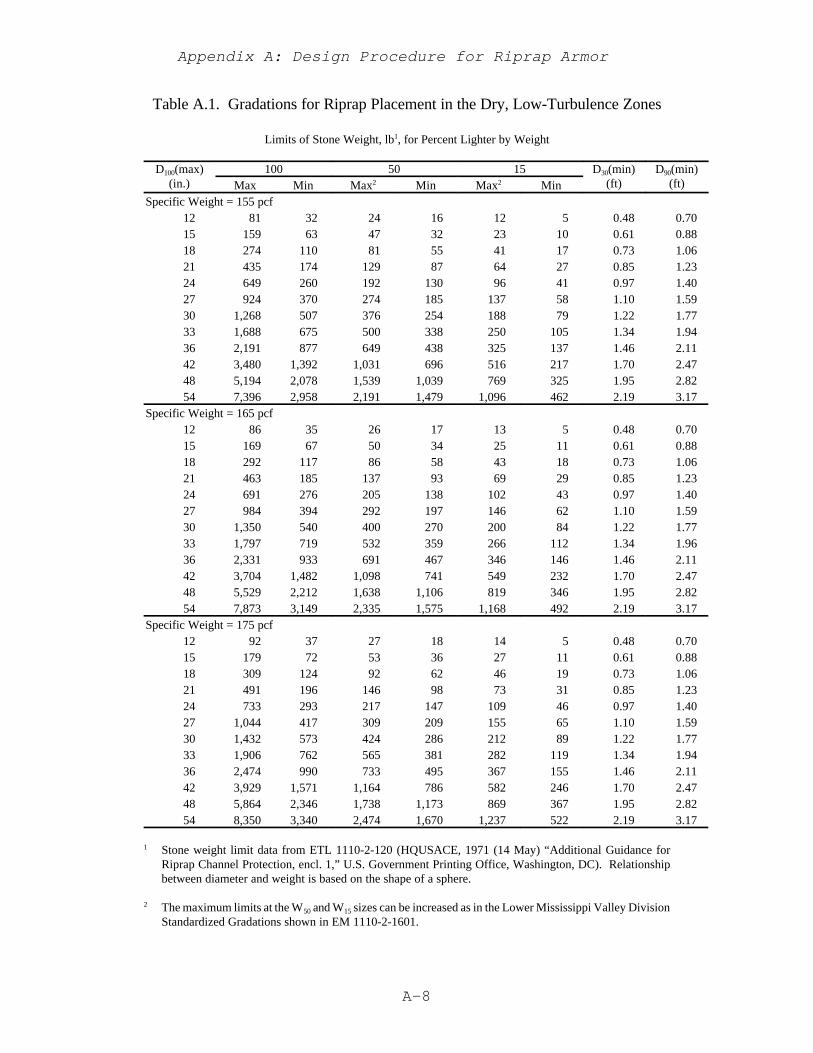
Appendix A: Design Procedure for Riprap Armor
A-8
Table A.1. Gradations for Riprap Placement in the Dry, Low-Turbulence Zones
Limits of Stone Weight, lb1, for Percent Lighter by Weight
D100(max)(in.)
100 50 15 D30(min)(ft)
D90(min)(ft)Max Min Max2 Min Max2 Min
Specific Weight = 155 pcf12 81 32 24 16 12 5 0.48 0.7015 159 63 47 32 23 10 0.61 0.8818 274 110 81 55 41 17 0.73 1.0621 435 174 129 87 64 27 0.85 1.2324 649 260 192 130 96 41 0.97 1.4027 924 370 274 185 137 58 1.10 1.5930 1,268 507 376 254 188 79 1.22 1.7733 1,688 675 500 338 250 105 1.34 1.9436 2,191 877 649 438 325 137 1.46 2.1142 3,480 1,392 1,031 696 516 217 1.70 2.4748 5,194 2,078 1,539 1,039 769 325 1.95 2.8254 7,396 2,958 2,191 1,479 1,096 462 2.19 3.17
Specific Weight = 165 pcf12 86 35 26 17 13 5 0.48 0.7015 169 67 50 34 25 11 0.61 0.8818 292 117 86 58 43 18 0.73 1.0621 463 185 137 93 69 29 0.85 1.2324 691 276 205 138 102 43 0.97 1.4027 984 394 292 197 146 62 1.10 1.5930 1,350 540 400 270 200 84 1.22 1.7733 1,797 719 532 359 266 112 1.34 1.9636 2,331 933 691 467 346 146 1.46 2.1142 3,704 1,482 1,098 741 549 232 1.70 2.4748 5,529 2,212 1,638 1,106 819 346 1.95 2.8254 7,873 3,149 2,335 1,575 1,168 492 2.19 3.17
Specific Weight = 175 pcf12 92 37 27 18 14 5 0.48 0.7015 179 72 53 36 27 11 0.61 0.8818 309 124 92 62 46 19 0.73 1.0621 491 196 146 98 73 31 0.85 1.2324 733 293 217 147 109 46 0.97 1.4027 1,044 417 309 209 155 65 1.10 1.5930 1,432 573 424 286 212 89 1.22 1.7733 1,906 762 565 381 282 119 1.34 1.9436 2,474 990 733 495 367 155 1.46 2.1142 3,929 1,571 1,164 786 582 246 1.70 2.4748 5,864 2,346 1,738 1,173 869 367 1.95 2.8254 8,350 3,340 2,474 1,670 1,237 522 2.19 3.17
1 Stone weight limit data from ETL 1110-2-120 (HQUSACE, 1971 (14 May) “Additional Guidance forRiprap Channel Protection, encl. 1,” U.S. Government Printing Office, Washington, DC). Relationshipbetween diameter and weight is based on the shape of a sphere.
2 The maximum limits at the W50 and W15 sizes can be increased as in the Lower Mississippi Valley DivisionStandardized Gradations shown in EM 1110-2-1601.
Appendix A: Design Procedure for Riprap Armor
A-9
Number of tons required;
Miles transported;
Cost of transportation per ton-mile;
Cost per ton for placement;
Quality control during construction (it is easier to ensureeven coverage with a narrow gradation than with a widegradation); and
Need for and cost of filter.
On large project involving many different design conditions, savings in totalcost can often be realized by using a few standard gradations, selecting the standardgradation next up from the computed gradation.
A.2.5 LAYER THICKNESS
All stones should be contained reasonably well within the riprap layerthickness to provide maximum resistance against erosive forces. Oversize stones,even in isolated spots, may result in riprap failure by precluding mutual support andinterlock between individual stones, causing large voids that expose filter and beddingmaterials, and creating excessive local turbulence that removes smaller size stone.Small amounts of oversize stone should be removed individually and replaced withproper size stones. When a quarry produces a large amount of oversized stone,consideration should be given to changing the quarrying method, using a grizzly (sievefor large rock) to remove the oversize stone, obtaining the stone from another source,or increasing the riprap layer thickness to contain the larger stone. The followingcriteria apply to the riprap layer thickness:
It should not be less than the spherical diameter of the upper limit W100 stoneor less than 1.5 times the spherical diameter of the upper limit W50 stone, whicheverresults in the greater thickness. The thickness thus determined should be increasedby 50 percent when the riprap is placed underwater to provide for uncertaintiesassociated with this type of placement. At one location in the Missouri River basinin the United States, divers and sonic sounders were used to reduce the underwaterthickness to 1.25 times the dry placement thickness.

Appendix A: Design Procedure for Riprap Armor
A-10
n ' K D90(min)1/6 (A.2)
A.3 CHANNEL CHARACTERISTICS
A.3.1 SIDE SLOPES
The stability of riprap bank revetment is affected by the steepness of channel sideslopes. Side slopes should not be steeper than 1V on 1.5H, except in special cases where itmay be economical to use larger hand-placed stone keyed well into the bank. Side slopesfrom 1V on 2H to 1V on 3H are recommended for riprap stability. The size of stone requiredto resist the erosive forces of channel flow increases when the side slope angle approachesthe angle of repose of a riprap revetment. Rapid water-level recession and piping-initiatedfailures are other factors in determining channel side slopes. Embankment stability analysisshould properly address soils characteristics, ground-water and river conditions, and probablefailure mechanisms.
A.3.2 CHANNEL ROUGHNESS, SHAPE, ALIGNMENT, AND INVERT SLOPE
As boundary shear forces and velocities depend on channel roughness, shape,alignment, and invert slope, these factors must be considered in determining the size of stonerequired for riprap revetment. Comparative cost estimates should be made for severalalternative channel plans to determine the most economical and practical combination ofchannel factors and stone size. Resistance coefficients (manning’s n) for riprap surfacesshould be estimated using the following form of Stricklers equation:
where
D50(min) = size of which 90 percent of sample is finer, from minimum or lower limitcurve of gradation specification (ft),
k = 0.036 average of all flume data,K = 0.034 for velocity and stone size calculation, and
= 0.038 for capacity and freeboard calculation.
The K values represent the upper and lower bounds of laboratory data determined for bottomriprap. Resistance data from a large laboratory channel having an irregular riprap surfacesimilar to riprap placed underwater resulted in a 15% increase in Manning’s n above the dryplacement values given above. These Manning n values represent only the grain resistanceof the riprap surface.
Appendix A: Design Procedure for Riprap Armor
A-11
A.4 DESIGN GUIDANCE FOR STONE SIZE
A.4.1 GENERAL
Riprap protection for open channels is subjected to hydrodynamic drag and lift forcesthat tend to erode the revetment and reduce its stability. Undermining by scour beyond thelimits of protection is also a common cause of failure. The drag and lift forces are created byflow velocities adjacent to the stone. Forces resisting motion are the submerged weight ofthe stone and any downward and lateral force components caused by contact with otherstones in the revetment. Characteristics of the available stone and the designer’s experienceplay a large part in determining size of riprap. This is particularly true on projects wherehydraulic parameters are ill-defined and the total amount of riprap required is small.
A.4.2 DESIGN CONDITIONS
Stone size computations should be conducted for flow conditions that produce themaximum velocity at the riprapped boundary. In many cases, velocities continue to increasebeyond bank-full discharge; but in some cases backwater effects or loss of flow into theoverbanks results in velocities that are less than those at bankfull. Channel bend riprap isconservatively designed for the point having the maximum force or velocity. For braidedchannels, bank-full discharges may not be the most severe condition. At lesser flows, flowis often divided into multiple channels. Flow in these channels often impinges abruptly onbanks or levees at sharp angles. Precise guidance is lacking in defining design conditions forbraided channels, although a correction factor for velocity is suggested.
A.4.3 STONE SIZE
The method presented here for determining stone size uses depth averaged localvelocity, since a designer will be better able to estimate local velocity than local boundaryshear. Local depth-averaged velocity and local flow depth are used in this procedure toquantify the imposed forces. Riprap size and submerged unit weight quantify the resistingforce of the riprap. This method is based on a large body of laboratory data and has beencompared to available prototype data (Maynord, 1988). This method defines the stability ofa wide range of gradations if placed to a thickness of 1D100(max). Guidance for thicknessgreater than 1D100(max) is presented. The method is applicable to side slopes of 1V on 1.5hor flatter.
(1) Velocity Estimation. The characteristic velocity for side slopes VSS is the depth-averaged local velocity over the slope at a point 20% of the slope length from thetoe of slope. The 20% location was selected because it represents the point ofmaximum side slope shear in straight channels. Various methods exist toestimate local depth-averaged velocity for use in this design procedure.Numerical methods include two-dimensional depth averaged models. Physical
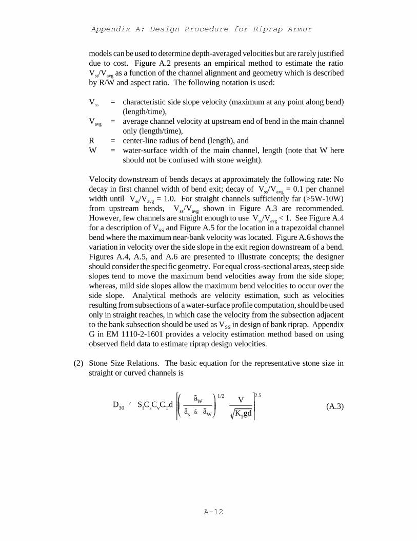
Appendix A: Design Procedure for Riprap Armor
A-12
D30 ' SfCsCvCTdãW
ãs & ãW
1/2V
K1gd
2.5
(A.3)
models can be used to determine depth-averaged velocities but are rarely justifieddue to cost. Figure A.2 presents an empirical method to estimate the ratioVss/Vavg as a function of the channel alignment and geometry which is describedby R/W and aspect ratio. The following notation is used:
Vss = characteristic side slope velocity (maximum at any point along bend)(length/time),
Vavg = average channel velocity at upstream end of bend in the main channelonly (length/time),
R = center-line radius of bend (length), andW = water-surface width of the main channel, length (note that W here
should not be confused with stone weight).
Velocity downstream of bends decays at approximately the following rate: Nodecay in first channel width of bend exit; decay of Vss/Vavg = 0.1 per channelwidth until Vss/Vavg = 1.0. For straight channels sufficiently far (>5W-10W)from upstream bends, Vss/Vavg shown in Figure A.3 are recommended.However, few channels are straight enough to use Vss/Vavg < 1. See Figure A.4for a description of VSS and Figure A.5 for the location in a trapezoidal channelbend where the maximum near-bank velocity was located. Figure A.6 shows thevariation in velocity over the side slope in the exit region downstream of a bend.Figures A.4, A.5, and A.6 are presented to illustrate concepts; the designershould consider the specific geometry. For equal cross-sectional areas, steep sideslopes tend to move the maximum bend velocities away from the side slope;whereas, mild side slopes allow the maximum bend velocities to occur over theside slope. Analytical methods are velocity estimation, such as velocitiesresulting from subsections of a water-surface profile computation, should be usedonly in straight reaches, in which case the velocity from the subsection adjacentto the bank subsection should be used as VSS in design of bank riprap. AppendixG in EM 1110-2-1601 provides a velocity estimation method based on usingobserved field data to estimate riprap design velocities.
(2) Stone Size Relations. The basic equation for the representative stone size instraight or curved channels is
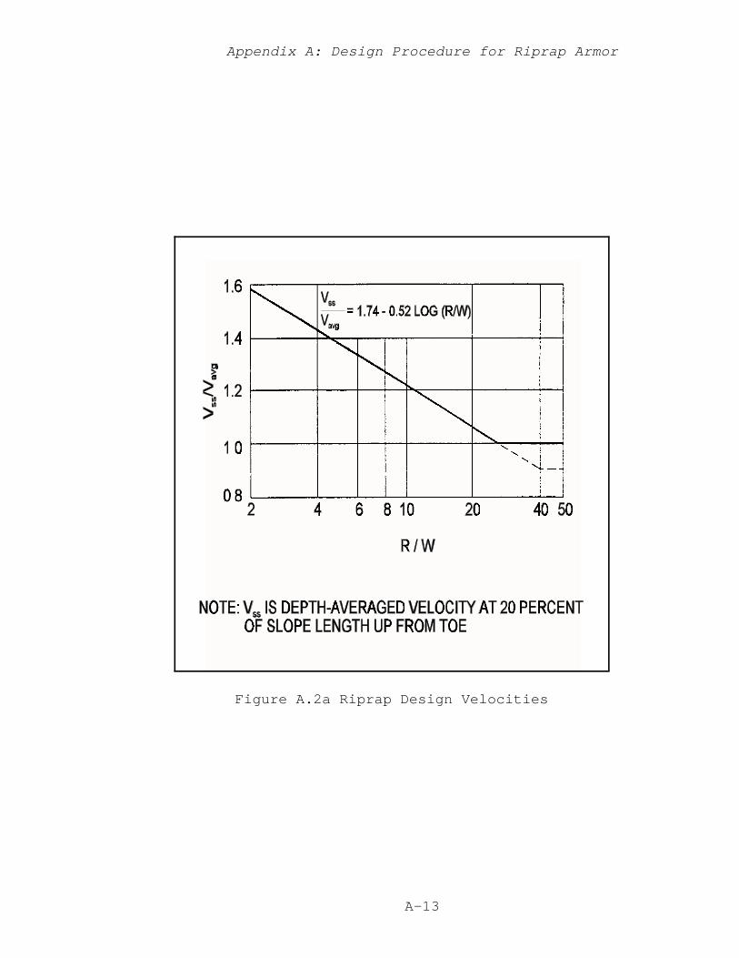
Appendix A: Design Procedure for Riprap Armor
A-13
Figure A.2a Riprap Design Velocities

Appendix A: Design Procedure for Riprap Armor
A-14
Figure A.2b Riprap Design Velocities
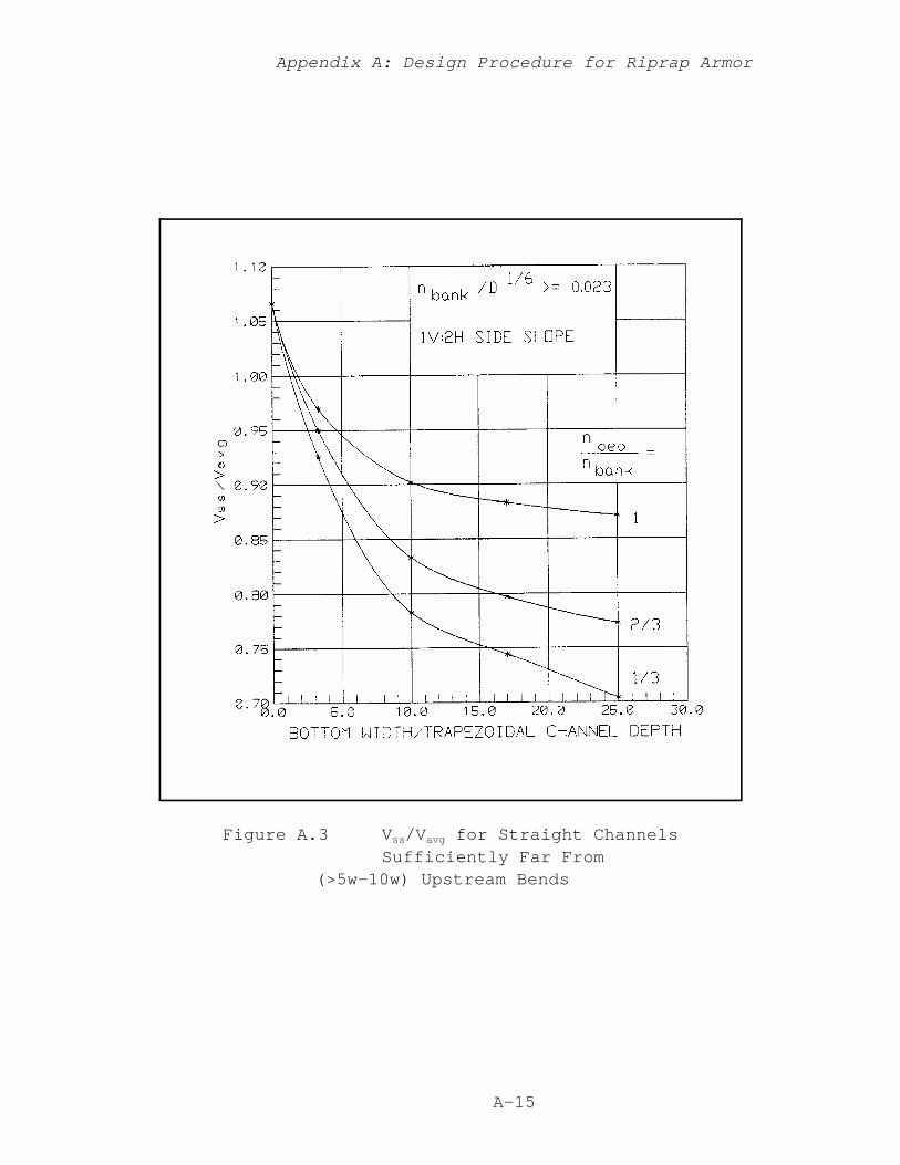
Appendix A: Design Procedure for Riprap Armor
A-15
Figure A.3 Vss/Vavg for Straight ChannelsSufficiently Far From
(>5w-10w) Upstream Bends
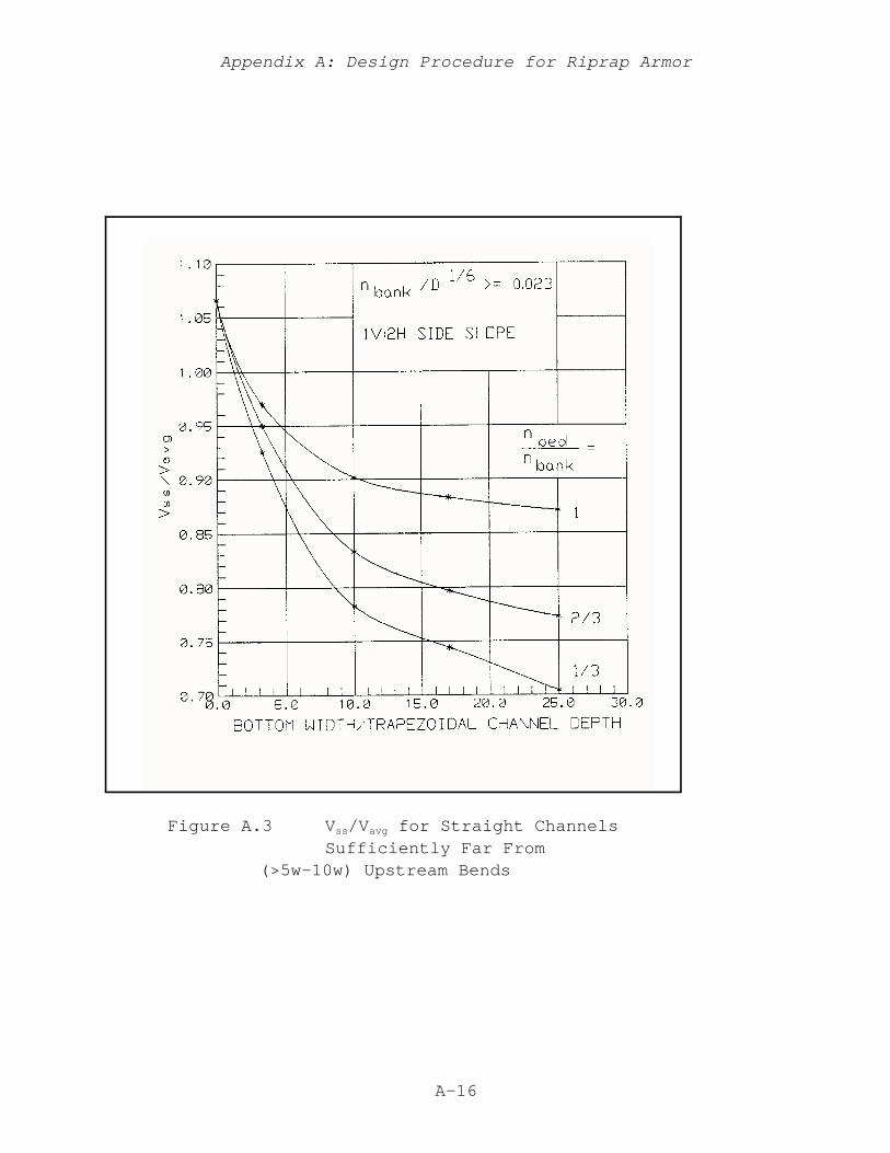
Appendix A: Design Procedure for Riprap Armor
A-16
Figure A.3 Vss/Vavg for Straight ChannelsSufficiently Far From
(>5w-10w) Upstream Bends
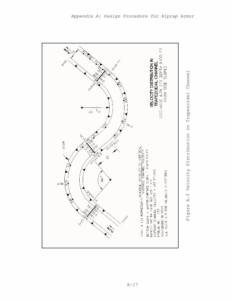
Appendix A: Design Procedure for Riprap Armor
A-17
Figure A.5 Velocity Distribution in Trapezoidal Channel
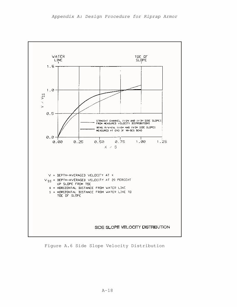
Appendix A: Design Procedure for Riprap Armor
A-18
Figure A.6 Side Slope Velocity Distribution
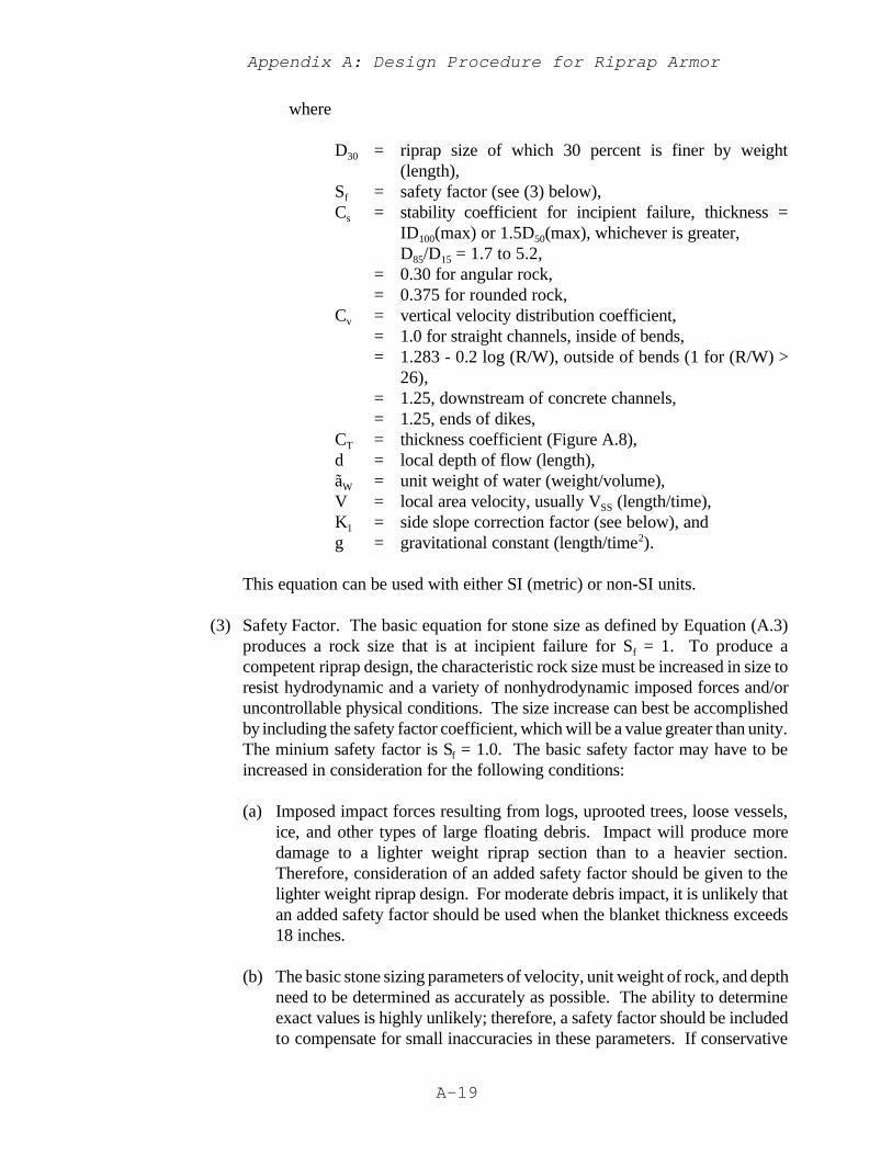
Appendix A: Design Procedure for Riprap Armor
A-19
where
D30 = riprap size of which 30 percent is finer by weight(length),
Sf = safety factor (see (3) below),Cs = stability coefficient for incipient failure, thickness =
ID100(max) or 1.5D50(max), whichever is greater,D85/D15 = 1.7 to 5.2,
= 0.30 for angular rock,= 0.375 for rounded rock,
Cv = vertical velocity distribution coefficient,= 1.0 for straight channels, inside of bends,= 1.283 - 0.2 log (R/W), outside of bends (1 for (R/W) >
26),= 1.25, downstream of concrete channels,= 1.25, ends of dikes,
CT = thickness coefficient (Figure A.8),d = local depth of flow (length),ãW = unit weight of water (weight/volume),V = local area velocity, usually VSS (length/time),K1 = side slope correction factor (see below), andg = gravitational constant (length/time2).
This equation can be used with either SI (metric) or non-SI units.
(3) Safety Factor. The basic equation for stone size as defined by Equation (A.3)produces a rock size that is at incipient failure for Sf = 1. To produce acompetent riprap design, the characteristic rock size must be increased in size toresist hydrodynamic and a variety of nonhydrodynamic imposed forces and/oruncontrollable physical conditions. The size increase can best be accomplishedby including the safety factor coefficient, which will be a value greater than unity.The minium safety factor is Sf = 1.0. The basic safety factor may have to beincreased in consideration for the following conditions:
(a) Imposed impact forces resulting from logs, uprooted trees, loose vessels,ice, and other types of large floating debris. Impact will produce moredamage to a lighter weight riprap section than to a heavier section.Therefore, consideration of an added safety factor should be given to thelighter weight riprap design. For moderate debris impact, it is unlikely thatan added safety factor should be used when the blanket thickness exceeds18 inches.
(b) The basic stone sizing parameters of velocity, unit weight of rock, and depthneed to be determined as accurately as possible. The ability to determineexact values is highly unlikely; therefore, a safety factor should be includedto compensate for small inaccuracies in these parameters. If conservative
Appendix A: Design Procedure for Riprap Armor
A-20
estimates of these parameters are used in the analysis, the added safetyfactor should not be used. The safety factor should be based on theanticipated error in the values used. It should not be relied on to correctinaccurate or assumed stone sizing parameters. The depth-averagedvelocity over the riprap is the parameter to which the rock size is the mostsensitive. A 10 percent change in the velocity will result in a nearly 100percent change in the weight limits of the riprap gradation (based on asphere) and about a 30 percent change in the riprap thickness. The riprapsize is also quite sensitive to the unit weight of the rock to be used: A 10percent change in the unit weight will result in a 70 percent change in theweight limits of the riprap gradation (based on a sphere) and about a 20percent change in the riprap thickness. The unit weight of the rock can bedetermined only from tests of samples from the quarry and is not exactlyrepresentative of all the rock that the quarry will produce. The rock size isnot nearly as sensitive to the depth parameter as to the other twoparameters, but depth should not be neglected. Reliable estimates for allthree parameters should be made before the inclusion of a safety factor.
(c) Vandalism and/or theft of the stones is a serious problem in urban areaswhere small riprap has been placed. A W50(min) of 80 pounds will reducethe effects of theft and vandalism. Sometimes grouted stone is used aroundvandalism-prone areas to prevent loss of riprap.
(d) The completed revetment will contain some pockets of undersized rocks, nomatter how much effort is devoted to obtaining a well-mixed gradationthroughout the revetment. This placement problem can be assumed tooccur on any riprap job to some degree but probably more frequently onjobs that require stockpiling or additional handling, and where improperplacement methods are used. Therefore a larger safety factor should beused when stockpiling, additional hauling, or poor placement methods willbe used.
(e) The safety factor should be increased where severe freeze-thaw isanticipated.
The safety factor based on each of the above considerations should beconsidered separately and then the largest of these values should be used inEquation (A.3).
Appendix A: Design Procedure for Riprap Armor
A-21
K1 ' 1 &sin2 è
sin2ö(A.4)
D50 'D85
D15
1/3
D30 (A.5)
(4) Applications.
(a) The outer bank of straight channels downstream of bends should bedesigned using velocities computed for the bend. The K1 side slope factoris normally defined by the Carter et al. (1953) relationship
whereè = angle of side slope with horizontal, andö = angle of repose of riprap material (normally 40 deg).
Results given in Maynord (1988) show that Equation (A.4) is conservativeand that the repose angle is not a constant 40 deg but varies with severalfactors. The recommended relationship for K1 as a function of è is given inFigure A.7 along with Equation (A.4) using ö = 40 deg. Correction for thevertical velocity distribution in bends is given in Figure A.8. Limited testinghas been conducted to determine the effects of blanket thickness greaterthan 1D100(max) on the stability of riprap. Results are shown in Figure A.8and require interpolation between the curves for each value of D85/D15.Gradations having D85/D15 greater than 5.2 should use the 5.2 curve. Whengreater blanket thickness is used, it must be realized that some rockmovement will occur before the revetment becomes stable. While D30 isconsidered to be the appropriate characteristic size, many designers preferto use D50. The required or computed D30 can be used to determine therequired D50 according to
(b) The basic procedure to determine riprap size using this method is as follows:
1. Determine average channel velocity for the design condition usingcomputational methods, physical modeling or extrapolation of on-sitemeasurement

Appendix A: Design Procedure for Riprap Armor
A-22
Figure A.7 Correction for Side Slope Angle
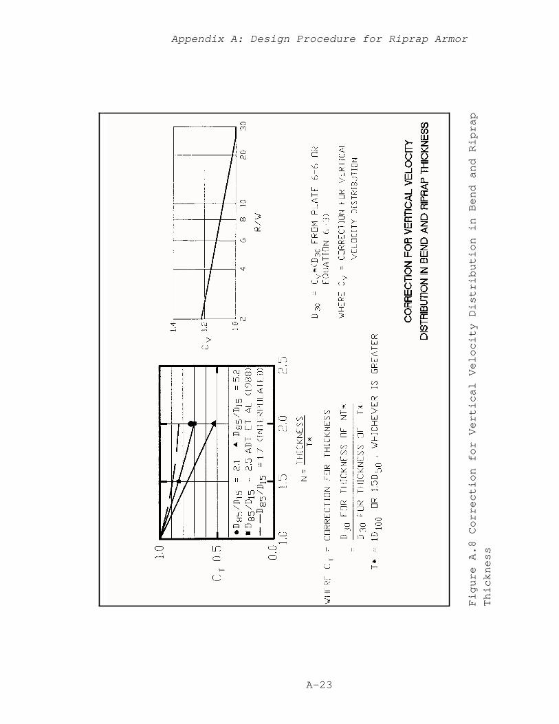
Appendix A: Design Procedure for Riprap Armor
A-23
Figure A.8 Correction for Vertical Velocity Distribution in Bend and Riprap
Thickness
Appendix A: Design Procedure for Riprap Armor
A-24
2. Find Vss using Figure A.2.3. Find D30 using Equation (A.3).4. Find gradation having D30(min) $ computed D30.
A PC-based computer program of this procedure is available from the U.S.Army Engineer Waterways Experiment Station.
(c) This procedure can be used in both natural channels with bank protectiononly and prismatic channels having riprap on bed and banks. Most bankprotection sections can be designed by direct solution. In these cases, theextent of the bank compared to the total perimeter of the channel means thatthe average channel velocity is not significantly affected by the riprap.Example 1 demonstrates this procedure.
1. Example 1
a. Problem. Determine stable riprap size for the outer bank of anatural channel bend in which maximum velocity occurs at bank-full flow. Water-surface profile computations at bank-full flowshow an average channel velocity of 7.1 feet per second and adepth at the toe for the outer bank of 15 feet. The channel issufficiently wide so that the added resistance on the outer bank willnot significantly affect the computed average channel velocity (truein many natural channels). Quarries likely to be used for theproject have rock weighing 165 pounds per cubic foot androutinely produce the 12-, 18-, and 24-inches D100(max) gradationsshown in Table A.1. A bank slope of 1V on 2H has been selectedbased on geotechnical analysis. A blanket thickness of 1D100(max)will be used in this design. Bend radius is 620 ft and water-surfacewidth is 200 ft.
b. Solution. Using Figure A.2, the maximum bend velocity (Vss) is1.48 (7.1) or 10.5 feet per second. The side slope depth at 20percent up the slope from the toe is 12 ft. Using Equation (A.3),the required D30 is 0.62 ft. From Table A.1, the 18-in. D100(max)gradation has D30(min) = 0.73 ft is the minimum routinely producedgradation that has D30(min) greater than or equal to 0.62 ft. In thisexample, the actual safety factor of (1.1(0.73/0.62)) = 1.3 resultsfrom using standard gradations to avoid the extra production costsincurred by specifying a custom gradation for every designcondition.

Appendix A: Design Procedure for Riprap Armor
A-25
(d) In some cases, a large part of the channel perimeter is covered with riprap;the average channel velocity, depth, and riprap size are dependent upon oneanother; and the solution becomes iterative. A trial riprap gradation is firstassumed and resistance coefficients are computed using Equation (A.2).Then the four steps described in paragraph (b) are conducted. If thegradation found in Step 4 is equal to the assumed trial gradation, thesolution is complete. If not a new trial gradation is assumed and theprocedure is repeated. Example 2 demonstrates this procedure.
2. Example 2
a. Problem. Determine stable riprap size in a bend of a trapezoidalchannel with essentially uniform flow. Bank slope is 1V on 2H andboth the bed and banks will be protected with the same size ofriprap. The bottom width is 140 ft, slope is 0.0017 ft/ft, and thedesign discharge is 13,500 cfs. Use 1D100(max) thickness and thesame quarry as in Problem 1. Bend radius is 500 ft and bend angleis 120 deg.
b. Solution. In this problem the solution is iterative; flow depth,velocity, and rock size depend on each other. Use Strictler’sequation n = 0.036 (D90(min))0.166 to estimate Manning’s resistancecoefficient. Bend velocity is determined using Figure A.2. Assumetrial gradation and solve for riprap size as shown in Tables A.2 andA.3. Use uniform flow computations to determine the following:
Table A.2 Uniform Flow Computations
TrialD100(max)
(in.)Manning’s
n
NormalDepth(ft)1
Water-Surface Width
(ft)
AverageVelocity
(fps)1
Side SlopeDepth
(ft)
121824
0.0340.0360.038
10.611.011.3
182.4184.0185.2
7.97.67.3
8.58.89.0
1 From iterative solution of Manning’s equation Q/A = (1.49/n)R2/3S1/2.
Use velocity estimation and riprap size equations to obtain riprapsize in Table A.3:
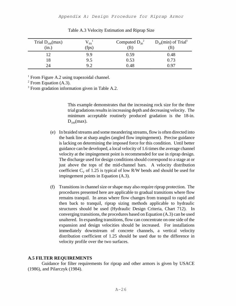
Appendix A: Design Procedure for Riprap Armor
A-26
Table A.3 Velocity Estimation and Riprap Size
Trial D100(max)(in.)
VSS1
(fps)Computed D30
2
(ft)D30(min) of Trial3
(ft)
121824
9.99.59.2
0.590.530.48
0.480.730.97
1 From Figure A.2 using trapezoidal channel.2 From Equation (A.3).3 From gradation information given in Table A.2.
This example demonstrates that the increasing rock size for the threetrial gradations results in increasing depth and decreasing velocity. Theminimum acceptable routinely produced gradation is the 18-in.D100(max).
(e) In braided streams and some meandering streams, flow is often directed intothe bank line at sharp angles (angled flow impingement). Precise guidanceis lacking on determining the imposed force for this condition. Until betterguidance can be developed, a local velocity of 1.6 times the average channelvelocity at the impingement point is recommended for use in riprap design.The discharge used for design conditions should correspond to a stage at orjust above the tops of the mid-channel bars. A velocity distributioncoefficient CV of 1.25 is typical of low R/W bends and should be used forimpingement points in Equation (A.3).
(f) Transitions in channel size or shape may also require riprap protection. Theprocedures presented here are applicable to gradual transitions where flowremains tranquil. In areas where flow changes from tranquil to rapid andthen back to tranquil, riprap sizing methods applicable to hydraulicstructures should be used (Hydraulic Design Criteria, Chart 712). Inconverging transitions, the procedures based on Equation (A.3) can be usedunaltered. In expanding transitions, flow can concentrate on one side of theexpansion and design velocities should be increased. For installationsimmediately downstream of concrete channels, a vertical velocitydistribution coefficient of 1.25 should be used due to the difference invelocity profile over the two surfaces.
A.5 FILTER REQUIREMENTSGuidance for filter requirements for riprap and other armors is given by USACE
(1986), and Pilarczyk (1984).
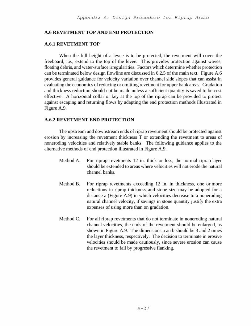
Appendix A: Design Procedure for Riprap Armor
A-27
A.6 REVETMENT TOP AND END PROTECTION
A.6.1 REVETMENT TOP
When the full height of a levee is to be protected, the revetment will cover thefreeboard, i.e., extend to the top of the levee. This provides protection against waves,floating debris, and water-surface irregularities. Factors which determine whether protectioncan be terminated below design flowline are discussed in 6.2.5 of the main text. Figure A.6provides general guidance for velocity variation over channel side slopes that can assist inevaluating the economics of reducing or omitting revetment for upper bank areas. Gradationand thickness reduction should not be made unless a sufficient quantity is saved to be costeffective. A horizontal collar or key at the top of the riprap can be provided to protectagainst escaping and returning flows by adapting the end protection methods illustrated inFigure A.9.
A.6.2 REVETMENT END PROTECTION
The upstream and downstream ends of riprap revetment should be protected againsterosion by increasing the revetment thickness T or extending the revetment to areas ofnoneroding velocities and relatively stable banks. The following guidance applies to thealternative methods of end protection illustrated in Figure A.9.
Method A. For riprap revetments 12 in. thick or less, the normal riprap layershould be extended to areas where velocities will not erode the naturalchannel banks.
Method B. For riprap revetments exceeding 12 in. in thickness, one or morereductions in riprap thickness and stone size may be adopted for adistance a (Figure A.9) in which velocities decrease to a nonerodingnatural channel velocity, if savings in stone quantity justify the extraexpenses of using more than on gradation.
Method C. For all riprap revetments that do not terminate in noneroding naturalchannel velocities, the ends of the revetment should be enlarged, asshown in Figure A.9. The dimensions a an b should be 3 and 2 timesthe layer thickness, respectively. The decision to terminate in erosivevelocities should be made cautiously, since severe erosion can causethe revetment to fail by progressive flanking.
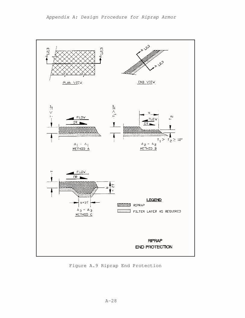
Appendix A: Design Procedure for Riprap Armor
A-28
Figure A.9 Riprap End Protection

Appendix A: Design Procedure for Riprap Armor
A-29
A.7 REVETMENT TOE SCOUR ESTIMATION AND PROTECTION
A.7.1 GENERAL
Toe scour is probably the most frequent cause of failure of riprap revetments. Thisis true not only for riprap, but also for a wide variety of protection techniques.
A.7.2 REVETMENT TOE PROTECTION
Toe protection may be provided by either of two general approaches:
(1) Place the lower extremity below the expected scour depth or found it onnoneroding material. This is the preferred method but it can be difficult andexpensive when underwater excavation is required.
(2) Place sufficient launchable stone at the toe to arrest toe erosion beforegeotechnical instability occurs. This approach has been successfully used onmany streams. It has experiences some failures where flow abruptly impinges onthe bankline, perhaps as a result of the design not adequately accounting for thiscondition.
Four specific applications of these two general approaches are illustrated in FigureA.10. Methods A and B are intended to extend to the maximum depth of scour. Method Cis suitable where significant toe scour is not expected. Method D can be adapted to a widerange of site conditions and scour depths. Constructability and the designer’s judgementdetermine which method is preferable for a specific project.
Method A. When toe excavation can be made in the dry, the riprap layer may beextended below the existing groundline a distance exceeding theanticipate depth of scour. If excavation quantities are prohibitive, theconcept of Method D can be adapted to reduce excavation.
Method B. When the bottom of the channel is non-erodible material, the normalriprap should be keyed in at streambed level.
Method C. When the riprap is to be placed underwater and little toe scour isexpected (such as in straight reaches that are not downstream ofbends), the toe may be placed on the existing bottom of height a andwidth c equal to 1.5T and 5T, respectively. This compensates foruncertainties of underwater placement (see A.8). When the anticipatederosion depth will undermine the stone toe, Method D should be used.
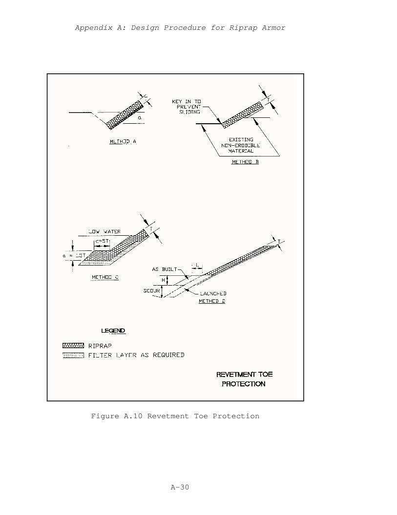
Appendix A: Design Procedure for Riprap Armor
A-30
Figure A.10 Revetment Toe Protection

Appendix A: Design Procedure for Riprap Armor
A-31
Method D. An extremely useful technique where water levels prohibit excavationfor a toe section is to place a launchable section at the toe of the bank.Even if excavation is practicable, this method may be preferred for costsavings if the cost of extra stone required to produce a launched stonerevetment is exceeded by the cost of excavation required to carry thedesign thickness T down the slope. This concept simply uses toe scouras a substitute for mechanical excavation. This method also has theadvantage of providing a “built-in” scour gage, allowing easymonitoring of high-flow scour by visual inspection of the remaining toestone after the high flow subsides, or by surveyed cross sections if thetoe stone is underwater. Additional stone can then be added forreinforcement if necessary. This method is also readily adaptable toemergency protection, where high flow and the requirement for quickaction make excavation impractical.
Shape of the stone toe is not critical. For trench-fill revetments, the height of thestone section is generally one-half to one times the length. For weighted riprap toes, heightsof 2.5 to 4.0 times the bank protection thickness should be used. Providing an adequatevolume of stone as discussed below is critical.
To compute the required launchable stone volume for Method D, the followingassumptions should be used:
Launch slope = 1V on 2H. This is the slope resulting from rock launched onnon-coehesive material in both model and prototype surveys. Launch slopeis less predictable if coehesive material is present, since cohesive material mayfail in large blocks.
Scour depth = existing elevation - maximum scour elevation.
Thickness after launching = thickness of the bank revetment T.
To account for the stone lost during launching and for underwater placement, theincreases in stone volume listed in Table A.4 are recommended. Using these assumptions, therequired stone volume for underwater placement for vertical launch distance less than 15 ftequals
Required Stone Volume = 1.5T times launch slope length
= 1.5T times scour depth 5= 3.35T (scour depth)
A safety factor should be added if data to compute scour depth are unreliable, ifcohesive bank material is present, or if monitoring and maintenance after construction cannotbe guaranteed. Widely graded ripraps are recommended because of reduced rock voids that
Appendix A: Design Procedure for Riprap Armor
A-32
tend to prevent leaching of lower bank material through the launched riprap. Launchablestone should have D85D15 $ 2.
Table A.4 Increase in Stone Volume for Riprap Launching Sections
Vertical Launch Distance(ft)1
Volume Increase Percent
Dry Placement Underwater Placement
# 15> 15
2550
5075
1 From bottom of launch section to maximum scour.
A.8 DELIVERY AND PLACEMENT
The common methods of riprap placement are hand placing; machine placing, suchas from a skip, dragline, or some form of bucket; and dumping from trucks and spreading bybulldozer. Hand placement produces the most stable riprap revetment if the long axis of theriprap particles are oriented perpendicular to the bank. It is the most expensive methodexcept when stone is unusually costly and/or labor unusually cheap. Steeper side slopes canbe used with hand-placed riprap than with other placing methods. This reduces the requiredvolume of rock and may be an attractive alternative where rights of way are restricted.However, the greater cost of hand placement usually makes machine or dumped placementmethods and flatter slopes more economical. Also, geotechnical considerations also dictatechannel side slope design. In the machine placement method, sufficiently small incrementsof stone should be released as close to their final positions as practical. Rehandling ordragging operations to smooth the revetment surface tend to result in segregation andbreakage of stone. Stone should not be dropped from an excessive height as this may resultin the same undesirable conditions. Riprap placement by dumping and spreading is notrecommended as significant segregation and breakage can occur. However in some cases,it may be economical to increase the layer thickness and stone size somewhat to offset theshortcomings of this placement method. Smooth, compact riprap sections have resulted fromcompacting the placed stone sections with a broad-tracked bulldozer. This stone must bequite resistant to abrasion. Thickness for underwater placement should be increased by 50percent to provide for the uncertainties associated with this type of placement. Underwaterplacement is usually specified in terms of weight of stone per unit area, to be distributeduniformly in a “grid” pattern established by survey control.
A.9 ICE AND DEBRIS
Ice and debris create greater stresses on riprap revetment by impact and flowconcentration effects. Ice attachment to the riprap also causes a decrease in stability. Onerule of thumb is that thickness should be increased by 6-12 in., accompanied by appropriate
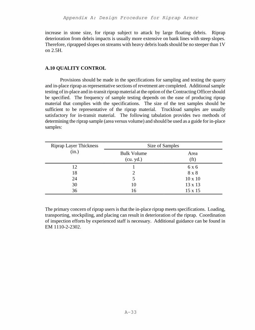
Appendix A: Design Procedure for Riprap Armor
A-33
increase in stone size, for riprap subject to attack by large floating debris. Riprapdeterioration from debris impacts is usually more extensive on bank lines with steep slopes.Therefore, riprapped slopes on streams with heavy debris loads should be no steeper than 1Von 2.5H.
A.10 QUALITY CONTROL
Provisions should be made in the specifications for sampling and testing the quarryand in-place riprap as representative sections of revetment are completed. Additional sampletesting of in-place and in-transit riprap material at the option of the Contracting Officer shouldbe specified. The frequency of sample testing depends on the ease of producing riprapmaterial that complies with the specifications. The size of the test samples should besufficient to be representative of the riprap material. Truckload samples are usuallysatisfactory for in-transit material. The following tabulation provides two methods ofdetermining the riprap sample (area versus volume) and should be used as a guide for in-placesamples:
Riprap Layer Thickness(in.)
Size of Samples
Bulk Volume(cu. yd.)
Area(ft)
1218243036
125
1016
6 x 68 x 8
10 x 1013 x 1315 x 15
The primary concern of riprap users is that the in-place riprap meets specifications. Loading,transporting, stockpiling, and placing can result in deterioration of the riprap. Coordinationof inspection efforts by experienced staff is necessary. Additional guidance can be found inEM 1110-2-2302.
Appendix A: Design Procedure for Riprap Armor
A-34
REFERENCES
Carter, A.C., Carlson, E.J., and Lane, E.W. (1953). Critical tractive forces on channel sideslopes in coarse, non-cohesive material, Hydraulic Laboratory Report No. HYD-366,U.S. Bureau of Reclamation, Denver, CO.
Maynord, S.T. (1988). Stable riprap size for open channel flows, Technical Report HL-88-4,U.S. Army Engineer Waterways Experiment Station, Vicksburg, MS, March.
Pilarczyk, K.W. (1984). Filters. In W. van Aalst (ed.), Chapter 2, The Closure of TidalBasins, Delft University Press, Delft, The Netherlands.
U.S. Army Corps of Engineers, Office, Chief of Engineers (1991). Hydraulic design of floodcontrol channels, EM 1110-2-1601, U.S. Government Printing Office, WashingtonDC.
U.S. Army Corps of Engineers, Office, Chief of Engineers (1990). Construction with largestone, EM 1110-2-2302, U.S. Government Printing Office, Washington DC.
U.S. Army Corps of Engineers, Office, Chief of Engineers (1971). Additional guidance forriprap channel protection, ETL 1110-2-120, U.S. Government Printing Office,Washington DC.
U.S. Army Corps of Engineers, Headquarters (1986). Seepage analysis and control for dams,EM 1110-2-1901, U.S. Government Printing Office, Washington DC.
U.S. Army Corps of Engineers, Office, Chief of Engineers (1988). Hydraulic design criteria,U.S. Government Printing Office, Washington DC.
Ahmed, A. (1987). Stability of riprap side slopes in open channels, Phd Thesis, Universityof Southampton.
Anderson, A.G. (1968). Tentative design procedure for riprap lined channels, NationalCooperative Highway Research Progam, St. Anthony Falls Hydraulic LaboratoryReport No. 96.
Blodgett, J.C., and McConaughy, C.E. (1986). Rock riprap design for protection of streamchannels near highway structures, Vol. 2, evaluation of riprap design procedures,Water Resources Investigations Report 86-4128, U.S. Geological Survey,Sacramento, CA.
California Division of Highways (1970). Bank and shore protection, State of California,Department of Public Works, Sacramento, CA.

Appendix A: Design Procedure for Riprap Armor
A-35
Stevens, M.A., Simons, D.B., and Lewis, G.L. (1976) Safety factor for riprap protection,Journal of the Hydraulics Division, ASCE, v. 102, no. HY5, pp. 637-655, May.
U.S. Department of Transportation, Federal Highway Administration (1989). Design ofriprap revetment, Hydraulic Engineering Circular No. 11.

Appendix A: Design Procedure for Riprap Armor
A-36

B-1
APPENDIX B
BIOENGINEERING FOR STREAMBANK EROSION CONTROL
Guidelines

Appendix B: Bioengineering for Streambank Erosion Control -- Guidelines
B-2
Appendix B: Bioengineering for Streambank Erosion Control -- Guidelines
B-3
1 Introduction
Background
Corps of Engineers (CE) and others are often restricted from using hard structures, suchas riprap or concrete lined channels, for streambank erosion control partly because ofenvironmental reasons and high cost. Within the last decade or so, increased demands havebeen placed upon the CE by environmental agencies and others to incorporate vegetation intotheir streambank erosion control projects rather than to rely completely on traditionalmethods. Complete bank armorment by various methods such as riprapped revetment,concrete revetment, bulkheads, concrete linings, etc. are considered by many to have littlevalue for fisheries, wildlife, water quality, and aesthetic appeal. Bioengineering, in contrast,is receiving more emphasis from environmental agencies and conservation organizations.Bioengineering is the combination of biological, mechanical, and ecological concepts tocontrol erosion and stabilize soil through the sole use of vegetation or in combination withconstruction materials. Both living and non living plants can be used. Non-living plants areused as construction materials, similar to engineered materials. The Planted vegetationcontrols erosion and serves as good wildlife and fisheries habitat in riparian systems.
A limited number of streambank erosion control projects have been designed andimplemented by the CE where bioengineering has been purposely planned as a part of theproject. The CE has historically relied on construction projects with design lifes of 50 to 100years that require a minimum amount of maintenance. Therefore, the focus of developmenthas been on hard structures that can be modeled and studied in hydraulic flumes and other teststructures and are designed to stay in place a long time. The CE has been reluctant to designsofter treatments, e.g., bioengineering, for erosion control because of a dearth of specificdesign guidance. For instance, under what velocity conditions will certain vegetativetreatments work? This type of information has been slow to develop. In part, a lack ofmonitoring after streambanks have been treated with a vegetative method has led to unknownperformance conditions and failure thresholds. In 1993, efforts were taken under the purviewof the Environmental Impact Research Program (EIRP), sponsored by Headquarters, USArmy Corps of Engineers, to develop and demonstrate bioengineering concepts forstreambank erosion control and to determine hydraulic velocities and conditions for successfulprototype performance and use.
Appendix B: Bioengineering for Streambank Erosion Control -- Guidelines
B-4
Purpose
This report synthesizes information related to bioengineering applications and providespreliminary planning and design guidelines for use of bioengineering treatments on erodedstreambanks. It can be used by both planning and design elements, not as a cookbook, butas a guide with tools to accomplish bioengineering projects. It presents a bioengineeringdesign model with examples in the text that describe specific case studies where certainstream conditions, such as velocities, have been provided. It also describes appropriate plantsto use, their acquisition, and their handling requirements.
This report is divided into two volumes. The main report, Volume I, providesbioengineering guidelines for streambank erosion control. Volume II presents several casestudies of bioengineering treatments applied to one or more streams in various geographiclocations around the continental United States.
Scope
The authors of this report do not attempt to assume that bioengineering for streambankprotection is a cure unto itself. First, bed stability, another whole subject area, must beachieved before banks are addressed. If streambeds are not stable, it does little good toattempt bank stabilization. This report does not attempt to address the details of fluvialgeomorphology, but the authors recognize that bioengineering must be done in consonancewith good river bed and planform stability design and there are several texts and engineermanuals that address these subjects. Consequently, good bioengineering takes aninterdisciplinary team approach with expertise representing engineering, physical, andbiological fields, as well as others, a point re-emphasized throughout this report. The authorsalso recognize that causes of streambank erosion are complex and can often be related toland-use practices being conducted in the watershed and/or in the immediate vicinity of theerosion problem on the streambank. Therefore, careful study should be made of the causesof erosion before bioengineering is contemplated. Again, an interdisciplinary team is oftenrequired to develop an optimum plan. Bioengineering must be done within the context of alandscape approach, but erosion control must be addressed by reaches, from a practicalstandpoint. The report provides a planning sequence, or bioengineering design model, thatis tailored to a zonal approach within reaches.
Vegetation, per se, is not a panacea for controlling erosion and must be considered in lightof site-specific characteristics. When vegetation is combined with low cost building materialsor engineered structures, numerous techniques can be created for streambank erosion control.This report summarizes a number of techniques that utilize vegetation. For understandinghow vegetation can be used in bioengineering and as a basis for conceptualizing abioengineering design model, it is important to understand both the assets and limitations ofusing planted vegetation.
Appendix B: Bioengineering for Streambank Erosion Control -- Guidelines
B-5
Assets of Using Planted Vegetation
Gray (1977), Bailey and Copeland (1961), and Allen (1978) discuss five mechanismsthrough which vegetation can aid erosion control: reinforce soil through roots (Gray, 1977);dampen waves or dissipate wave energy; intercept water; enhance water infiltration; anddeplete soil water by uptake and transpiration. Klingman and Bradley (1976) point out fourspecific ways vegetation can protect streambanks. First, the root system helps hold the soiltogether and increases the overall bank stability by its binding network structure, i.e., theability of roots to hold soil particles together. Second, the exposed vegetation (stalks, stems,branches, and foliage) can increase the resistance to flow and reduce the local flow velocities,causing the flow to dissipate energy against the deforming plant rather than the soil. Third,the vegetation acts as a buffer against the abrasive effect of transported materials. Fourth,close growing vegetation can induce sediment deposition by causing zones of slow velocityand low shear stress near the bank, allowing coarse sediments to deposit. Vegetation is alsooften less expensive than most structural methods, it improves the conditions for fisheries andwildlife, improves water quality, and can protect cultural/archeological resources.
Limitations of Using Planted Vegetation
Using planted vegetation for streambank erosion control also has limitations. These mayinclude its occasional failure to grow; it is subject to undermining; it may be uprooted bywind, water, and the freezing and thawing of ice; wildlife or livestock may feed upon anddepredate it; and it may require some maintenance. Most of these limitations, such asundermining, uprooting by freezing and thawing, etc., can often be lessened or prevented byuse of bioengineering measures.
Appendix B: Bioengineering for Streambank Erosion Control -- Guidelines
B-6
2 Bioengineering Design Model
A conceptual design model is offered below that leads one through the steps of planningand implementing a bioengineering project. It draws largely upon similar thought processespresented by Leiser (1992) for use of vegetation and engineered structures for slopeprotection and erosion control. Where appropriate, the report will reference examples in themain text (Vol. I) and case studies (Vol. II) that describe particular bioengineering treatmentson selected and monitored stream systems. The model includes planning and its associatedcomponents that will be defined below; use of hard structures and bioengineering; avegetative zonal concept; and various bioengineering fixes by zone. Monitoring, followup,and care should naturally follow.
Planning
A bioengineering project may be primarily desired for erosion control, but often there areother considerations. Thought should be given to important functions that the bioengineeringtreatment can perform, such as habitat development, archeological site protection, waterquality improvement, aesthetics, or a combination of these. The political and economicalrequirements or constraints of implementing any project must be considered. Anybioengineering streambank stabilization project should be planned within the context of thelandscape in which the stream is located. Activities near the stream that is influencing itserosion must be identified. It is a wasted effort to install bioengineering treatments in an areawhere cattle are allowed access to the treated reach immediately after construction. Thestream must be examined as a system, but the restoration must be accomplished at the reachlevel from a practical perspective. The planning part of the model should address potentialfunctions of the treatment and the political and economical concerns (Figure 1).
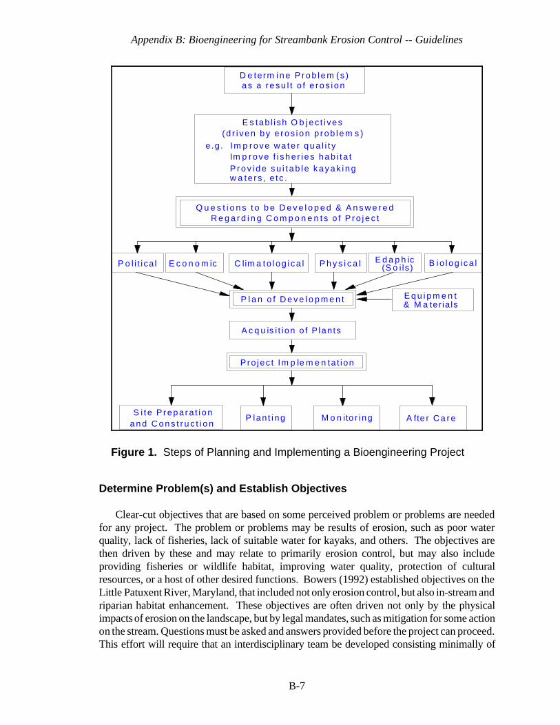
Appendix B: Bioengineering for Streambank Erosion Control -- Guidelines
B-7
P o l i t i ca l E c o n o m ic C lim a t o l o g i c a l P h y s i c a l B io l og i ca lE d a p h ic(S o i ls)
E q u i p m e n t
S i t e P repa ra t i ona n d C o n s t r u c t i o n
P lan t i ng M o n ito r i ng A fte r C a r e
& M a ter ia ls
E s tab l i sh O b jec t i ves( d r i v e n b y e r o s i o n p r o b l e m s )
e .g . Im p rove wa te r qua l i t yIm p rove f i she r i es hab i t a tP r o v i d e s u i t a b l e k a y a k i n gw a te rs , e t c .
D e term i n e P r o b l e m (s )as a r esu l t o f e ros i on
P l a n o f D e v e l o p m e n t
A c q u is i t i on o f P lan ts
Pro jec t Im p le m e n ta t ion
Q u e s t i o n s t o b e D e v e l o p e d & A n s w e r e dR e g a r d i n g C o m p o n e n t s o f P r o j e c t
Figure 1. Steps of Planning and Implementing a Bioengineering Project
Determine Problem(s) and Establish Objectives
Clear-cut objectives that are based on some perceived problem or problems are neededfor any project. The problem or problems may be results of erosion, such as poor waterquality, lack of fisheries, lack of suitable water for kayaks, and others. The objectives arethen driven by these and may relate to primarily erosion control, but may also includeproviding fisheries or wildlife habitat, improving water quality, protection of culturalresources, or a host of other desired functions. Bowers (1992) established objectives on theLittle Patuxent River, Maryland, that included not only erosion control, but also in-stream andriparian habitat enhancement. These objectives are often driven not only by the physicalimpacts of erosion on the landscape, but by legal mandates, such as mitigation for some actionon the stream. Questions must be asked and answers provided before the project can proceed.This effort will require that an interdisciplinary team be developed consisting minimally of

Appendix B: Bioengineering for Streambank Erosion Control -- Guidelines
B-8
engineers, hydrologists, and life scientists with expertise in bioengineering approaches. Otherdisciplines, such as economists, sociologists, and attorneys can be consulted as needed duringthe planning stage of development.
Questions to be Developed and Answered.
Any streambank erosion control project has several components. Each component mayhave constraints that have to be overcome. These components with associated constraintsare interdependent and must be considered, thus generating an abundance of questions thatshould be answered, if possible. They include the political, economic, climatatological,physical, edaphic (soils), and biological components of the project. Both the asking andanswering of these questions relative to these components lead to the Plan of Development.Once the plan is developed and permits acquired, procurement of plants will be required (SeePart III). After or concurrent with this procurement, implementation of the plan can proceed.The political component includes governmental regulations, such as those presented inSection 404 of the The Clean Water Act (formerly known at the Federal Water PollutionControl Act, 33 U.S.C. 1344). It also includes public pressures, such as restrictingbioengineering to the use of only native plant species or plants that are grown in a nursery asopposed to those harvested from the wild. Governmental regulations and/or public pressuresmay also mandate that certain vegetation species or types of species be used. If a certainspecies blocks the view of a river in an urban setting, for instance, public pressures may causeplans to change to use a different species or a different erosion control treatment altogether.Lack of grazing controls, limitations on use of chemicals for rodent, insect, or weed controlor fertilizers are other examples of these constraints and must be considered in anybioengineering design criteria protocol. The political component also includes the negativehuman factors of vandalism and trespass by foot and off road vehicles as well as the positivefactor of public pressure for improvement of the environment.
The economic component could be one of the more important factors to enablebioengineering erosion control efforts. Usually, bioengineering projects are less expensivethan traditional engineering approaches. However, economics invariably affects the finaldecisions on the selection of plant species and planting densities, as well as pre-projectexperimentation and after care activities. A bioengineering design protocol must includefunding for monitoring and allow for remedial planting and management of the site to meetthe objectives of the project. Bioengineering projects will often require more funds early inthe project's history for possible repair and assurance of effectiveness than traditionalengineering, but will be more self sustaining and resilient over the long term. If traditionalengineering projects need remediation over the life of the project (and they frequently do),the remediation occurs later in the life of the project but with higher overall costs.
The climatatological component includes several aspects of a project site: rainfall (amountand distribution), temperature (heat and cold, time, duration, and intensity), humidity, daylength, etc. Climatatological components affect plant species selection, how those plants willbe planted, and treatment after planting. With some exceptions, bioengineering projects inhumid regions with ample rainfall and projects along permanent flowing streams will probably
Appendix B: Bioengineering for Streambank Erosion Control -- Guidelines
B-9
require less effort to establish vegetation than those along intermittent flowing streams in dryclimates. In desert climates, where fewer plants in the inventory can be chosen than in humidclimates, learning these plants' life requisites is essential for successful planting. Theprobability for bioengineering project failure is higher with fewer species planted and wheregrowth stresses are greater.
The physical component includes physical parameters of a project: site stability such assubsidence or accretion; aspect (direction slope faces), which in turn influences environmentalfactors such as temperature (south and southwest facing sites are hotter andevapotranspiration is higher than on other directions); hydrodynamic aspects such as watersources (groundwater, surface water), and water frequency, timing, depth, duration andflooding relationship to bank height; fluvial geomorphology, such as historical streammeander, pattern, cross-sectional and longitudinal profiles, and energy sources such as waveand current action; and geomorphic features, such as landforms and terrain influences, e.g.,impacts of off-site water sources.
From the above list of physical parameters, hydrologic and geomorphic factors areparticularly important. For purposes of determining where to use vegetation on the bank andthe kinds of vegetation to use and when to plant, one needs a knowledge of the stream'shydrographic and fluvial geomorphic characteristics. If stream guage data are not available,one will have to rely on high water marks, the knowledge of persons living in the areas, andany other data derived from local vegetation and soils that indicate flood periodicity. Table1 gives an example of hydrologic characteristics of the upper Missouri River. It shows thefrequency of various flows and their duration with 25,000 cfs being the normal flow from latespring through fall. A 40,000 cfs flow with a duration of 6 months can be expected to occuronce every 10 years. Figure 2 subsequently shows the approximate water level correspondingto various river flows using the level of 25,000 cfs as the reference. At a flow of 40,000 cfs,the river level will be approximately 3 feet above the reference level. From other data, wealso know that flows exceed normal usually in June or July; therefore, planting should occurin early spring or fall.
This data also gives information that leads to forming vegetation planting zones. Weknow that for this example, a daily high flow of 35,000 cfs translates to a zone 2-ft high onthe bank that could occur once for 60 days every two years. This means that this zone willhave to be vegetated with extremely flood-tolerant vegetation, e.g., emergent aquatic species,willow (Salix spp.), and is equivalent to a “splash zone” that will be discussed later.

Appendix B: Bioengineering for Streambank Erosion Control -- Guidelines
B-10
Figure 2. River levels and flows of upper Missouri River below GarrisonDam
Table 1. Recurrence interval by discharge and duration on upper MissouriRiver*
Duration
Probability Of Not
Occurring
Discharge 6 Months 60 Days 1 Day (60 Days)
60,000 CFS --- 1/100 Yrs. 1/20 Yrs. 99%
50,000 CFS 1/100 1/10 1/5 90%
40,000 CFS 1/10 1/3 1/2 67%
35,000 CFS 1/3 1/2 1 50%
30,000 CFS 1/2 1 1 1%
25,000 CFS 1 --- --- ---
(Normal Flow Levels) - occurs generally from April 15 - May 15 until No. 15
CFS = Cubic feet per second
* From Logan et al. (1979 op cit.)
Appendix B: Bioengineering for Streambank Erosion Control -- Guidelines
B-11
Geomorphic characteristics such as bank geometry play a major part in the employmentof bioengineering. Banks that have been eroded and undercut to a very steep, unplantableslope require grading prior to planting (Edminster et al. 1949 and Edminster 1949). Theangle required varies with the soil, equipment used, and several other factors. Sand, forinstance, has an angle of repose of about 30 degrees whereas clay can stand on a muchsteeper angle (Gray 1977). Most slopes that accommodate revegetation are less than 1-1.2V:1 H. On steep banks where undercutting may be a problem, the toe of the bank may needprotecting with riprap or other hard, structural treatments. Special structural treatments otherthan vegetation and drainage structures may be necessary where geomorphic featurescontribute to internal erosion of the bank, called piping or sapping. This is where water canseep into the bank from higher elevations through porous strata and cause bank failure whenthe erodible strata are gone. Sometimes, bioengineering with appropriate geotextile filterscan treat piping problems, but not always.
The edaphic component includes all the soil parameters: texture, structure, fertility,erodability, chemistry, etc. Soil texture, structure, and depth all affect the water holdingcapacity of a soil and need to be considered when determining water retention requirementsor supplemental irrigation requirements during dry periods of the year. In addition toensuring proper bank slopes and bank toe protection, attention should be given to the edaphiccomponent that may in turn require some site preparation activities. It is desirable to haveslopes covered with at least a 10-cm layer of topsoil high in organic matter; this can bestockpiled prior to any grading. Movement of soil, however, is expensive and must beconsidered in light of the economic practicality. In lieu of moving rich topsoil, the existingsubstrate may be amended with fertilizer and mulch to help produce a better soil. In any case,plants need a growing medium that supports the plant and facilitates nutrient and wateruptake. The site may require other soil amendments such as lime, gypsum, or other specialnutrients depending upon the soil's pH and fertility. Soil tests should be conducted prior torevegetation to determine any amendments needed.
The biological component is one of the most important components and is interdependentwith the other components. It includes habitat requirements of animal and plant species andthe plan can be modified to some extent to meet these requirements if the life requisites ofthese species are known. This component also includes the availability of suitable plantspecies that, in part, make up the habitat for various riparian animals. Choices must be madebetween native and introduced species, plants obtained from commercial nurseries, or fromthe wild. This component also includes the propagation and cultural practice for the plants,planting, and aftercare. It includes plant diseases, insects, predators, and the presence orabsence of grazing animals. An example of spider mite damage is presented in the case studyof Court Creek, Illinois, Volume II, where willow had to be sprayed with an insecticide tocontrol damage. If spraying had not occurred, streambank protection with living willowwould not have been achieved. Protective screen sleeves or deer and grazing animalexclosures must be provided if these risks are present. The potential for damage from insect,rodent, deer, and other predation must be considered and protection provided to plantedwetland vegetation.
Appendix B: Bioengineering for Streambank Erosion Control -- Guidelines
B-12
The biological attributes of an area containing a bioengineering site are very important andplants are no exception. They are there because they have adapted to the ecologicalconditions of the area, such as climate, soils, etc. To use bioengineering effectively, oneshould learn to identify and evaluate plants that are growing in the area that have becomeadapted. These should include plants that are growing along all parts of the streambank,lower, middle, and upper. In bioengineering, these conditions and species should be emulatedas much as possible. Native plants or plants that have become naturalized in the area shouldnormally be used. Exotic plants should be avoided since there are species that may get outof control and become nuisances. One only has to look at examples such as purple loosestrife(Lythrum salicaria) to gain an appreciation of the problems exotic plants can cause.
Plants chosen should have some tolerance to flooding. Some will need to be highlytolerant (those planted lower on the bank) while others (those planted higher on the bank) canbe less tolerant. Plants chosen also will have to withstand some dry conditions as well asflooded conditions because of the fluctuating nature of water levels in streams.
A mixture of grasses, herbs, shrubs, and trees should be used, if possible, to provide adiversity of wildlife habitats. Some legumes such as yellow sweet clover (Melilotusofficinalis), white sweet clover (M. alba), and crownvetch (Coronilla varia) are possiblechoices because of their nitrogen-fixing attributes. These, however, should be used at anelevation subject to only intermittent and short periods of flooding, such as in the upper bankand terrace zones discussed below.
Plan of Development
The plan of development is the culmination of answering all the questions in the variouscategories mentioned above. Many of the questions regarding the above components can beanswered off site, but a site analysis is mandatory before plants can be procured or beforeproject implementation can occur. In the site analysis, each component must again beexamined to include the various factors or parameters and what will influence vegetationdevelopment for bioengineering and the stability of a streambank. A general guideline for thesite analysis is to be a keen observer as to the conditions occurring at the project reach as wellas upstream and downstream from it. From observations of a reference site, many answerscan be found about what kinds of plants to use, invader species that are apt to occur, causesof problems, such as overgrazing, road construction upstream contributing to a high bed loadof sediment, etc. The same or similar plant species that occur at the reference site should beacquired. In a site analysis, much of the data from a reference streambank area can be takento answer the questions posed.
Appendix B: Bioengineering for Streambank Erosion Control -- Guidelines
B-13
Equipment and Materials
In the plan of development, consideration should be given to the equipment and materialsrequired for vegetation handling and planting at the implementation stage. The tools requiredand the planting techniques will depend on the type of vegetation, i.e., woody or herbaceous,the size of plants, soils, and the size of the project and site conditions. Freshwater herbaceousplantings with low wave or current energy environments may call for tools like spades,shovels, and buckets. In contrast, high energy environments of waves and currents mayrequire tools for bioengineering installations. Such tools include chain saws, lopping and handpruners for the preparation of woody cuttings, and materials for woody bioengineeringmethods; or heavy hammers and sledges for driving stakes in bioengineering treatments suchas wattling and brush matting. Specialized equipment may be required. This is true whenmoving sod or mulches containing wetland plants or plant propagules. It is also true sincebioengineering projects often have the constraints of working in a pristine stream systemwhere riparian corridors are extremely valuable, particularly in large, urban settings. It is inthese settings that equipment size and type constraints are often placed upon the project.Thus, downsized front-end loaders and walking excavators are sometimes required tominimize disturbance of existing vegetation and soil. Other equipment and materials mayinclude fertilizers, soil amendments, (i.e. lime), fencing for plant protection, and irrigationequipment for keeping plants alive during dry conditions. Other equipment and materials forkeeping plants alive before they are planted may include shading materials such as tarps,buckets with water for holding plants, and water pumps and hoses for watering or watertrucks.
Permit Acquisition
After the site analysis and bioengineering actions are determined, necessary permits mustbe obtained, such as those governing any action impacting wetlands, water quality,cultural/historical resources, threatened and endangered species, and navigation. Usually andespecially on smaller streams not requiring large structures or bank shaping as a part of thedesign, the permit process will not be very complex or time consuming. However, on largestreams where deflection structures are employed or where banks are extensively shaped,navigation, cultural resource, and wetland permits can take several months to acquire.
Acquisition of Plants
Prior to the implementation of the project, the plans for acquiring plants must be madewell in advance (sometimes 1 - 2 years). To select vegetation for the project, vegetationexisting on or near a site and on similar nearby areas which have revegetated naturally are thebest indicators of the plant species to use. If commercial plant sources are not available(USDA, Soil Conservation Service, 1992), then on- or off-site harvesting can be considered.When acquiring plants, care must be given to local or federal laws prohibiting such plantacquisition and decimating the natural stands of wetland plants. Additionally, care must be
Appendix B: Bioengineering for Streambank Erosion Control -- Guidelines
B-14
taken to assure that pest species, such as purple loosestrife, are not collected and transferredto the project site.
The availability of plants of the appropriate species, size, and quality is often a limitingfactor in the final selection and plant acquisition process. Some native plant species are verydifficult to propagate and grow and many desirable species are not commonly available incommerce, or not available as good quality plants. As demand increases and nurserymen gainmore experience in growing native plant species, this limitation should become less important(Leiser, 1992). Plant species composition and quantity can often be determined from theproject objectives and functions desired. As a general rule, it is advisable to specify as manyspecies as possible and require the use of some minimum number of these species. Maximumand minimum numbers of any one species may be specified. See Part III for additionalinformation on plant acquisition, times of planting, and plant handling techniques.
Implementation
Implementation is the natural followup to the plan of development and is integrated withthe planning process. It cannot really be separated from it. It is the final stage of theconceptual and detailed design but may require feedback into design plan formulation forpossible on-site corrections. It includes site preparation and construction, planting,monitoring, and aftercare. For the bioengineering design to be successful, it must have closesupervision throughout by someone familiar with implementation of bioengineering projects. This stage requires close attention to detail. It is important in this stage to maintaincontinuity of the same interdisciplinary team who planned and designed the project and keepthem involved in this part of the project. Those capable of actually carrying out the projectshould be a team of persons with knowledge and experience of both stream morphology andmechanics, hydraulic and geotechnical engineering, and bioengineering. Regardingvegetation, the person should possess both training and experience in wetlands plant scienceand development. It is mandatory that person be on site intermittently at least during projectconstruction and especially planting. All of the efforts to address the various componentsof design will be in vain unless plants are handled and cared for properly when planted andeven after planting in many cases.
Planting Techniques
There are several planting techniques for bioengineering ranging from simple digging withshovels or spades and inserting sprigs (rooted stems) or cuttings to moving large pieces ofrooted material, such as sod, mulch, and root pads (large rooted shrubs). Other methodsconsist of direct seeding, hydroseeding, or drilling individual seeds such as acorns of wetlandoak species. All of the above methods capitalize on combining the attibutes of plants withsome kind of engineered material or structure or relying on the plant itself to form a resistantstructure to erosion, such as a live willow post revetment. Various techniques will bediscussed in detail below.
Appendix B: Bioengineering for Streambank Erosion Control -- Guidelines
1 Ms. Robin Sotir, personal communication, President, Robin Sotir and Associates, Marietta, Georgia
B-15
Monitoring and Aftercare
Most importantly, monitoring and necessary aftercare must be a part of anybioengineering design and must be included in the plan of development and theimplementation stage. The intensity and frequency of monitoring and aftercare will dependon site conditions, such as harshness of climate, probability of animal disturbance, high waveor current conditions, etc., and on established success criteria.
On many sites, it is essential to protect plantings from damage by animals, such as Canadageese (Branta canadensis), or beaver (Casta canadensis) and other mammals. The use ofirrigation may be required during aftercare and will improve growth and survival of plantingsthat are installed during dry seasons and in dry soils. The decision about irrigation must bemade based on economics contrasting the need to irrigate with the cost of possible mortalityand the consequences of failing to obtain the desired erosion control and other functions. SeePart IV for more detail on monitoring.
Hard Structures and Bioengineering
Generally speaking, bioengineering is considered “a soft fix.” This is not necessarily thecase. On first or second order streams, the sole use of vegetation with perhaps a little wireand a few stakes for holding the vegetation until it is established makes bioengineering moreof a soft treatment. However, bioengineering is used also in combination with hardstructures. These hard structures are used to protect the toe of the bank from undercuttingand the flanks (ends of treatment) from eroding. The larger the stream or stronger the flow,the more probable that hard structures will be incorporated into the bioengineering designmodel. This is also true when risks become greater, such as when an expensive facility isbeing threatened. As an example, a utility tower along a stream in Georgia1 was beingthreatened by erosion. A rock revetment had previously been used in front of the tower, butwas washed out. A bioengineering treatment that incorporated live willow whips and a logcrib were installed to control erosion. Crib logs controlled undercutting and flanking whilethe live willow whips installed between the log stringers developed and strengthened theoverall structure and gave it a “green” appearance.
In most of the case studies presented in Volume II, and in the references made to otherbioengineering streambank erosion control, hard structures such as rock riprap, log/tree
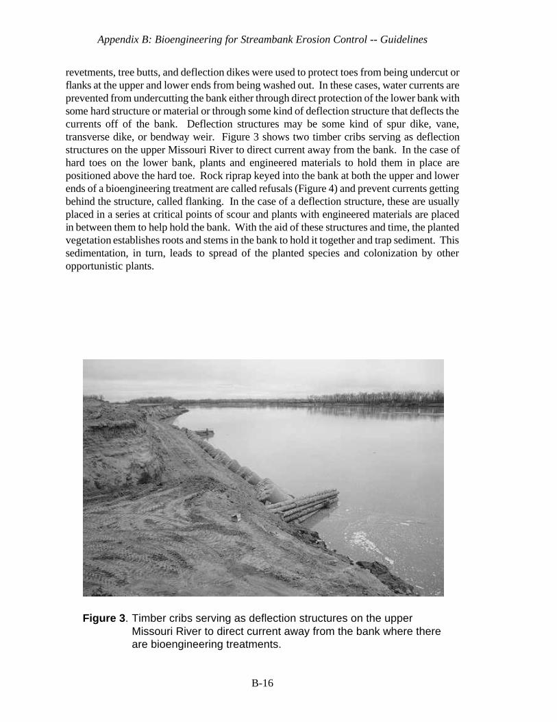
Appendix B: Bioengineering for Streambank Erosion Control -- Guidelines
B-16
Figure 3. Timber cribs serving as deflection structures on the upperMissouri River to direct current away from the bank where thereare bioengineering treatments.
revetments, tree butts, and deflection dikes were used to protect toes from being undercut orflanks at the upper and lower ends from being washed out. In these cases, water currents areprevented from undercutting the bank either through direct protection of the lower bank withsome hard structure or material or through some kind of deflection structure that deflects thecurrents off of the bank. Deflection structures may be some kind of spur dike, vane,transverse dike, or bendway weir. Figure 3 shows two timber cribs serving as deflectionstructures on the upper Missouri River to direct current away from the bank. In the case ofhard toes on the lower bank, plants and engineered materials to hold them in place arepositioned above the hard toe. Rock riprap keyed into the bank at both the upper and lowerends of a bioengineering treatment are called refusals (Figure 4) and prevent currents gettingbehind the structure, called flanking. In the case of a deflection structure, these are usuallyplaced in a series at critical points of scour and plants with engineered materials are placedin between them to help hold the bank. With the aid of these structures and time, the plantedvegetation establishes roots and stems in the bank to hold it together and trap sediment. Thissedimentation, in turn, leads to spread of the planted species and colonization by otheropportunistic plants.
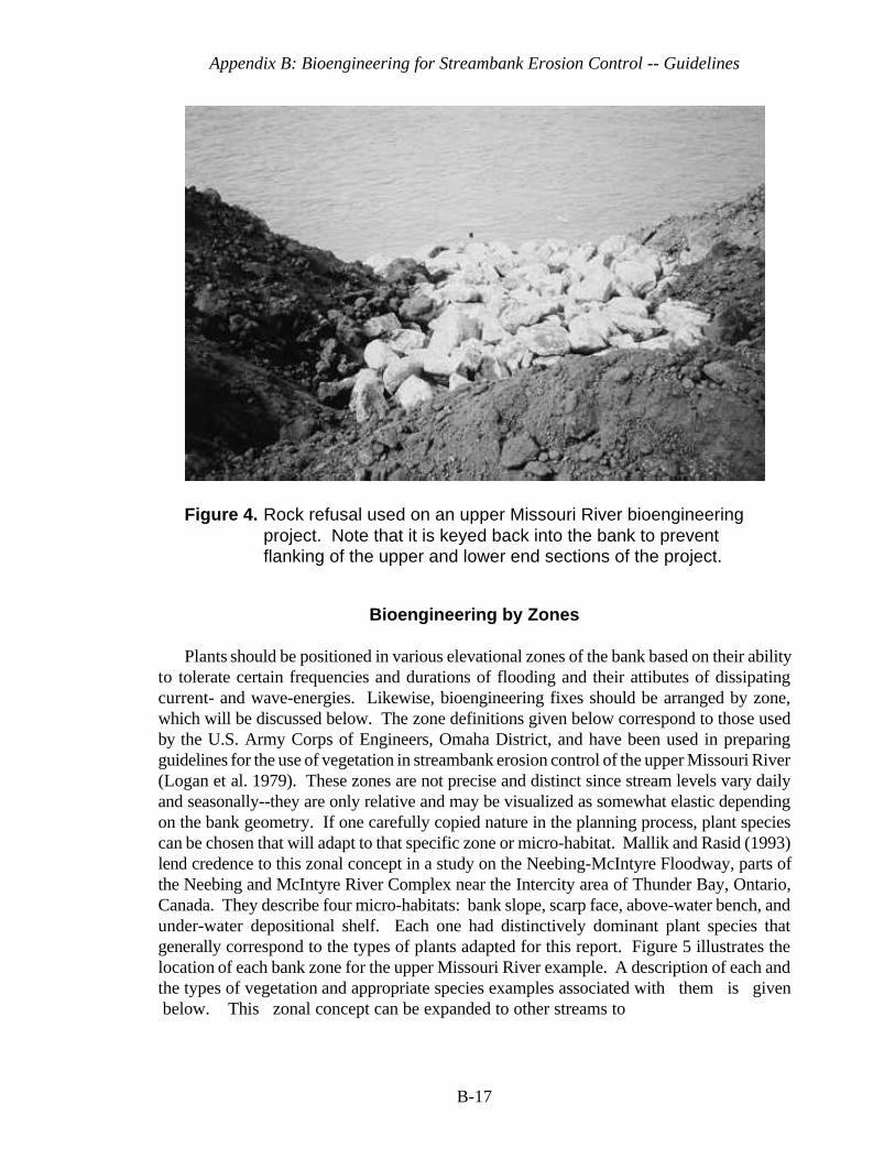
Appendix B: Bioengineering for Streambank Erosion Control -- Guidelines
B-17
Figure 4. Rock refusal used on an upper Missouri River bioengineeringproject. Note that it is keyed back into the bank to preventflanking of the upper and lower end sections of the project.
Bioengineering by Zones
Plants should be positioned in various elevational zones of the bank based on their abilityto tolerate certain frequencies and durations of flooding and their attibutes of dissipatingcurrent- and wave-energies. Likewise, bioengineering fixes should be arranged by zone,which will be discussed below. The zone definitions given below correspond to those usedby the U.S. Army Corps of Engineers, Omaha District, and have been used in preparingguidelines for the use of vegetation in streambank erosion control of the upper Missouri River(Logan et al. 1979). These zones are not precise and distinct since stream levels vary dailyand seasonally--they are only relative and may be visualized as somewhat elastic dependingon the bank geometry. If one carefully copied nature in the planning process, plant speciescan be chosen that will adapt to that specific zone or micro-habitat. Mallik and Rasid (1993)lend credence to this zonal concept in a study on the Neebing-McIntyre Floodway, parts ofthe Neebing and McIntyre River Complex near the Intercity area of Thunder Bay, Ontario,Canada. They describe four micro-habitats: bank slope, scarp face, above-water bench, andunder-water depositional shelf. Each one had distinctively dominant plant species thatgenerally correspond to the types of plants adapted for this report. Figure 5 illustrates thelocation of each bank zone for the upper Missouri River example. A description of each andthe types of vegetation and appropriate species examples associated with them is given below. This zonal concept can be expanded to other streams to
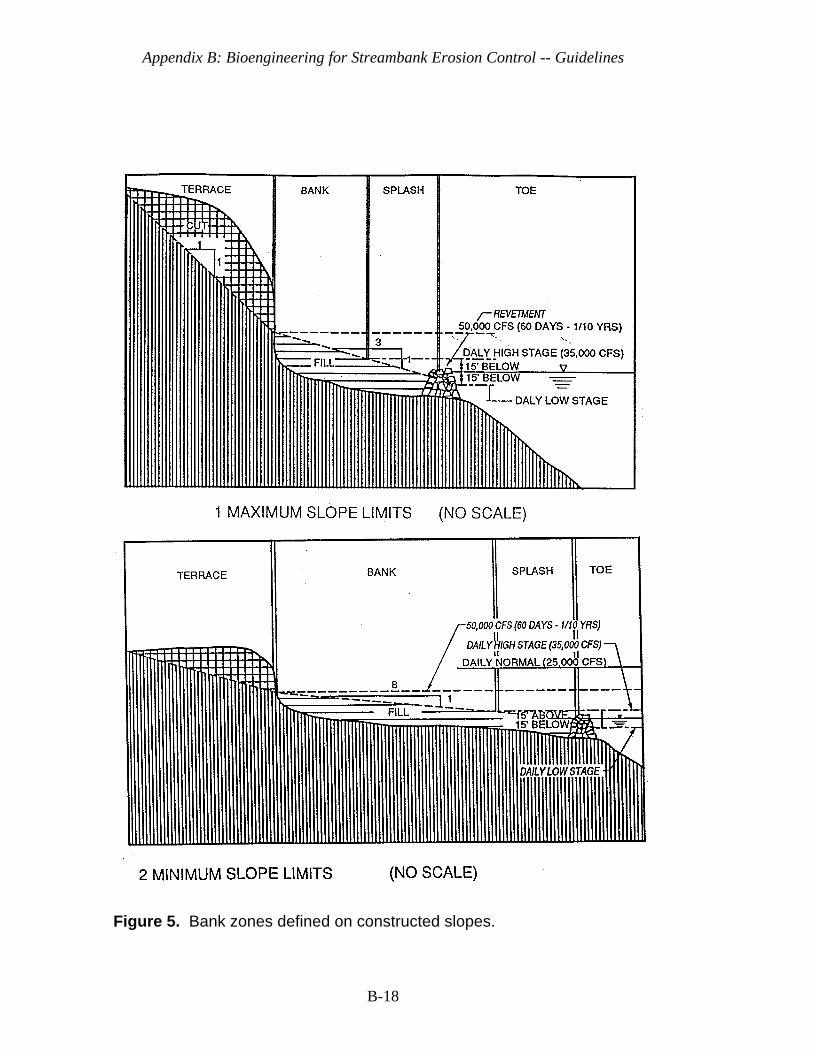
Appendix B: Bioengineering for Streambank Erosion Control -- Guidelines
B-18
Figure 5. Bank zones defined on constructed slopes.
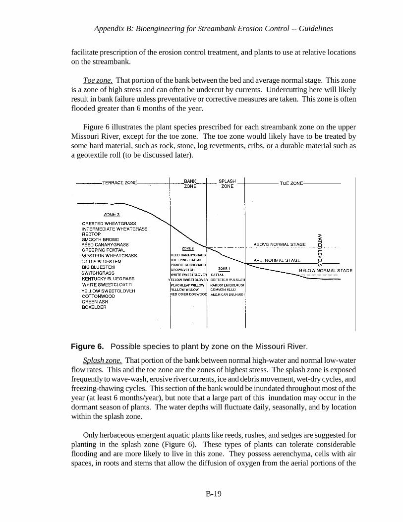
Appendix B: Bioengineering for Streambank Erosion Control -- Guidelines
B-19
Figure 6. Possible species to plant by zone on the Missouri River.
facilitate prescription of the erosion control treatment, and plants to use at relative locationson the streambank.
Toe zone. That portion of the bank between the bed and average normal stage. This zoneis a zone of high stress and can often be undercut by currents. Undercutting here will likelyresult in bank failure unless preventative or corrective measures are taken. This zone is oftenflooded greater than 6 months of the year.
Figure 6 illustrates the plant species prescribed for each streambank zone on the upperMissouri River, except for the toe zone. The toe zone would likely have to be treated bysome hard material, such as rock, stone, log revetments, cribs, or a durable material such asa geotextile roll (to be discussed later).
Splash zone. That portion of the bank between normal high-water and normal low-waterflow rates. This and the toe zone are the zones of highest stress. The splash zone is exposedfrequently to wave-wash, erosive river currents, ice and debris movement, wet-dry cycles, andfreezing-thawing cycles. This section of the bank would be inundated throughout most of theyear (at least 6 months/year), but note that a large part of this inundation may occur in thedormant season of plants. The water depths will fluctuate daily, seasonally, and by locationwithin the splash zone.
Only herbaceous emergent aquatic plants like reeds, rushes, and sedges are suggested forplanting in the splash zone (Figure 6). These types of plants can tolerate considerableflooding and are more likely to live in this zone. They possess aerenchyma, cells with airspaces, in roots and stems that allow the diffusion of oxygen from the aerial portions of the
Appendix B: Bioengineering for Streambank Erosion Control -- Guidelines
B-20
plant into the roots (Mitsch and Gosselink, 1986). Therefore, they can extend roots intodeeper water than many other types of plants, such as woody plants. Reeds, such as commonreed (Phragmites australis), and sedges, such as bulrushes (Scirpus spp.), also protectstreambanks in various ways. Their roots, rhizomes, and shoots bind the soil under the water,sometimes even above the water (Seibert 1968). In the reed zone, as Seibert (1968) definesit, they form a permeable underwater obstacle which slows down the current and waves byfriction, thereby reducing their impact on the soil. Active protection of the bank can beensured by reeds only in an area which is constantly submerged (Seibert 1968).
It should be mentioned that common reed is often considered a pest in the U.S. whereit has been observed as a monotypic plant that does not offer habitat diversity. The authorswould submit that this is true where there is not much of an elevation and hydrologic gradient.In other words, on shallow flats that become periodically inundated, it can thrive. However,when it is on a shoreline and becomes inundated over about 18 inches, it is often replaced byother more water tolerant species. One should use caution on where this plant is used andmatch it to one's objectives.
Various wetland grasses, sedges, and other herbs were used in this zone as a part of a coirgeotextile roll in an urban park setting in Allentown, Pennsylvania. The main vegetativecomponents of erosion control of the stream embankment are: lake sedge (Carex lacustris),stubble sedge (C. stipata), and woodland bulrush (Scirpus sylvaticus). Other minorcomponents used for diversity and color included: rice cut-grass (Leersia oryzoides), othersedges (C. lata, C. lanuginosa, C. hysterina, and C. prasina), softstem bulrush (Scirpusvalidus), blue flag iris (Iris versicolor), and monkey flower (Mimulus ringens). The lattertwo species were provided primarily for additional diversity and color (Siegel, 1994a). Siegelreported that these plants, along with bioengineering methods such as the coir roll, stabilizeda streambank that was subjected to storm events. In fact, the methods were designed toaccentuate and enlarge the existing floodplain to act as a buffer zone for floods associatedwith storms greater than the 25-yr event (Siegel, 1994b). The vegetation list above only givesone examples of types of species that were used for erosion control in the splash zone, i.e.,flood-tolerant and fast growing grasses and sedges. Care should be exercised in selectingspecies that are adapted to the project's geographic area. Local university botanists andUSDA Natural Resources Conservation Service (NRCS, formerly Soil Conservation Service)district personnel can be consulted for suitable species.
Herbaceous emergent aquatic plants, like those shown in Figure 6, must be used on astreambank that has a geometric shape conducive to such plants. Caution must be used onstreams that have heavy silt loads that could suffocate plants. These plants must grow infairly shallow water, from +45 to -152 cm (Allen et al., 1989). Sometimes, it is impossibleor impractical to find or shape a stream to match those conditions. Then, flood-tolerantwoody plants, like willow (Salix spp.), dogwood (Cornus spp.), and alder (Alnus spp.) areused in the splash zone. Again, a good rule of thumb is to look at the natural system andobserve what is growing there and try to duplicate it.
Appendix B: Bioengineering for Streambank Erosion Control -- Guidelines
B-21
Bank zone. That portion of the bank usually above the normal high-water level; yet, thissite is exposed periodically to wave-wash, erosive river currents, ice and debris movement,and traffic by animals or man. The site is inundated for at least a 60-day duration once everytwo to three years. The water table in this zone frequently is close to the soil surface due toits closeness to the normal river level.
In the bank zone, both herbaceous (i.e., grasses, clovers, some sedges and other herbs)and woody plants are used. These should still be flood tolerant and able to withstand partialto complete submergence for up to several weeks. Allen and Klimas (1986) list several grassand woody species that can tolerate from 4 to 8 weeks of complete inundation. This list,should not be considered exhaustive, however. Whitlow and Harris (1979) provide a listingof very flood-tolerant woody species and a few herbaceous species by geographic area withinthe United States that can be used in the bank zone.
Skeesick and Sheehan (1992) report on several other herbaceous and woody plants thatcan withstand tens of feet of inundation over 3 to 4 months in two different reservoirsituations in Oregon. These same species are often found along streambanks. Localuniversity botanists and plant material specialists within the NRCS should be consulted whenseeking flood-tolerant plants . Various willows can be used in this zone, but they should beshrublike willows such as sandbar willow (S. exigua) and basket willow (S. purpurea var.nana). Edminster et al. (1949) and Edminster (1949) describe successful use of basket willowfor streams and rivers in the Northeast. Shrub-like willow, alder, and dogwood species havebeen used in Europe successfully (Seibert 1968). Red-osier dogwood (Cornus stolonifera)and silky dogwood (C. amomum) also have been used in the Northeast (Edminster et al. 1949and Edminster 1949). Seibert (1968) notes that in periods of high water, the upper branchesof such shrubs reduce the speed of the current and thereby the erosive force of the water.The branches of these have great resilience, springing back after currents subside.
Terrace zone. That portion of the bank inland from the bank zone; it is usually notsubjected to erosive action of the river except during occasional flooding. This zone mayinclude only the level area near the crest of the unaltered “high bank” or may include sharplysloping banks on high hills bordering the stream.
The terrace zone is less significant for bank protection because it is less often flooded, butcan be easily eroded when it is flooded if vegetation is not present. Vegetation in this zoneis extremely important for intercepting floodwaters from overbank flooding, serving to reducesuper-saturation and decrease weight of unstable banks through evapotranspiration processesand for tying the upper portion of the streambank together with its soil-binding root network.Coppin and Richards (1990) provide a detailed explanation of plant evapotranspiration, butsummarize by saying, “ Apart from increasing the strength of soil by reducing its moisturecontent, evapotranspiration by plants reduces the weight of the soil mass. This weightreduction can be important on vegetated slopes where the soil may be potentially unstable.”
As denoted in Figure 6, the terrace zone can contain native grasses, herbs, shrubs, andtrees that are less flood tolerant than those in the bank zone, but still somewhat flood tolerant.
Appendix B: Bioengineering for Streambank Erosion Control -- Guidelines
B-22
The tree species also become taller and more massive. Trees are noted for their value instabilizing banks of streams and rivers (Seibert 1968; Leopold and Wolman, 1957; Wolmanand Leopold, 1957; Lindsey et al. 1961; and Sigafoos 1964). The trees have much deeperroots than grasses and shrubs and can hold the upper bank together. The banks of somerivers are not eroded for durations of 100 to 200 years because heavy tree roots bind thealluvium of floodplains (Leopold et al. 1957; Wolman and Leopold 1957; and Sigafoos 1964).A combination of trees, shrubs, and grasses in this zone will not only serve as an integratedplant community for erosion control, but will improve wildlife habitat diversity and aestheticappeal.
Bioengineering Treatments
The entire streambank should be treated to furnish a maximum array of plants capable ofproviding proper ground cover and root penetration for erosion protection, wildlife habitat,water quality improvement, and many other benefits. At times, the planting sites or zonesmay be quite narrow in width or difficult to distinguish depending on the geomorphology ofthe stream. The entire bank in these cases should be treated as a systematic arrangement ofplants and treatment practices.
Toe Zone
This is the zone that will need to be protected from undercutting with treatments such asstone or rock revetments, gabions, lunkers, log revetments, deflector dikes, cribs, rock andgeotextile rolls, root wads, or a combination of materials. The zone rarely has vegetationemployed in it alone, but when vegetation is employed, it is used in combination withmaterials that extend below the normal flow of water and above it. The principle is to keephigh velocity currents from undercutting the bank either through armoring the bank ordeflecting the currents away from the site of concern. Vegetation can then be used eitherabove the armor or in between and above the deflecting structure.
Stone or rock revetments in a bioengineering application are used at the toe in the zonebelow normal water levels and up to where normal water levels occur. Sometimes, the stoneis extended above where normal flow levels occur depending on the frequency and durationof flooding above this level. Then, vegetation is placed above it in a bioengineeringapplication. Stream guage information helps in making this judgement. Unfortunately, thereare no set guidelines for how far up the bank to carry the revetment except to say that itshould be applied below the scour zone up to at least the level where water runs the majorityof the year. Engineering Manual 1110-2-1601, Change 1 (Corps of Engineers, 1994) givesguidelines for riprap toe protection.
One such rock revetment for toe protection was used in conjunction with vegetationabove it on Crutcho Creek, Tinker Air Force Base, Oklahoma (Figure 7). In this example,the creek is flashy and often reaches or exceeds the top of bank during the spring of each year

Appendix B: Bioengineering for Streambank Erosion Control -- Guidelines
1 Herr Lothar Bestmann, personal communication, President, Ingenieurbiologie,Wedel,Germany, May 9, 1996.
B-23
for a few days. The rock toe extended from the bed to about 1/3 the height of the bank(Figure 8). This treatment has been successful in this type of setting after several floodsexceeding the top of the bank.
Rock toes are also used streamward or just below other materials such as hay bales orgeotextile rolls. In one example, Omaha District recently used rock riprap below a large haybale cylinder covered with a fabric (rope mesh) made from woven fibers of coconut huskscalled coir. The riprap weighed about 1.5 Tons/ft and was about 3.5-ft deep. Then,vegetation in the form of dormant willow poles (discussed below) was placed above this(Figures 9 and 10).
In another example, a rock roll (Figure 11) was used on the Rhine River in Dusseldorf,Germany, below an installation of wetland vegetation grown in geotextile mats made fromcoir. The large rock was wrapped in a polyethylene type of rope mesh and installed in thefollowing fashion: 1) a ditch is dug; 2) the rope mesh is placed in the ditch so that enoughof it is overhanging the ditch on the riverward side to wrap around the rock and have someleft on the shoreward side on which to place more rock; 3) the rock is placed on the ropemesh; 4) the rope mesh is wrapped around the rock with a portion of it running up theshoreward side; and finally 5) more rock is backfilled on top of the rope mesh to hold it allfirmly in place. This rock roll serves to protect the treatment from undercutting. The ropemesh contains smaller rocks and strengthens the system and is similar to the function ofgabions which are discussed below. It should be mentioned that this whole system of rockrolls and geotextile mats with wetland grasses or grass-like plants, such as sedges, wereplaced in between large rock transverse dikes (Figure 12). The dikes were already therebefore this treatment was installed and divert river currents away from the banks. The rockroll (toe protection), the transverse dikes, and the geotextile coir mats, work together toobtain wetland plant establishment and erosion control. Prior to the installation of plants,even though the transverse dikes were present, an asphalt revetment used to control erosionfailed because water got behind the asphalt and pushed it out. This system has been in placefrom 1991 to present and has withstood a large flood in 1994, the largest in the last decade,with more than a 7 m fluctuation above normal flow. The flood overtopped the treatment forseveral months. Because of the wetland plants' flood tolerance, the rock toe, and transversedikes, they survived and are still controlling erosion. A key wetland plant species instrumentalin the treatment's success was a sedge, Carex hirta2.

Appendix B: Bioengineering for Streambank Erosion Control -- Guidelines
B-24
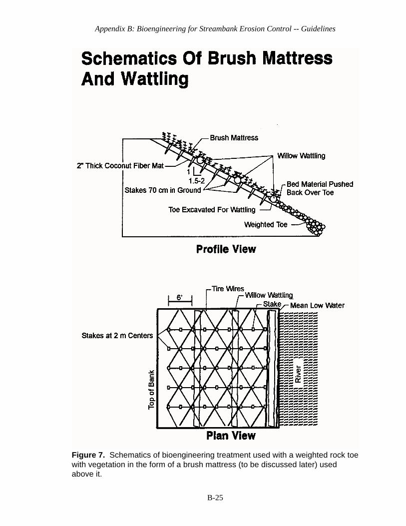
Appendix B: Bioengineering for Streambank Erosion Control -- Guidelines
B-25
Figure 7. Schematics of bioengineering treatment used with a weighted rock toewith vegetation in the form of a brush mattress (to be discussed later) usedabove it.
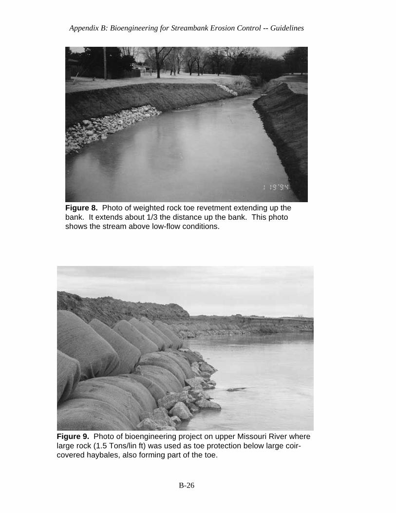
Appendix B: Bioengineering for Streambank Erosion Control -- Guidelines
B-26
Figure 8. Photo of weighted rock toe revetment extending up thebank. It extends about 1/3 the distance up the bank. This photoshows the stream above low-flow conditions.
Figure 9. Photo of bioengineering project on upper Missouri River wherelarge rock (1.5 Tons/lin ft) was used as toe protection below large coir-covered haybales, also forming part of the toe.
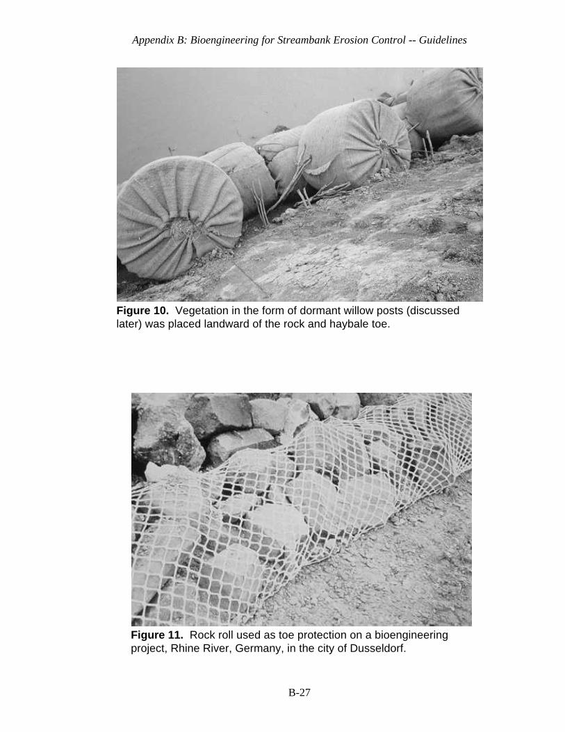
Appendix B: Bioengineering for Streambank Erosion Control -- Guidelines
B-27
Figure 10. Vegetation in the form of dormant willow posts (discussedlater) was placed landward of the rock and haybale toe.
Figure 11. Rock roll used as toe protection on a bioengineeringproject, Rhine River, Germany, in the city of Dusseldorf.
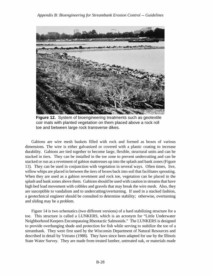
Appendix B: Bioengineering for Streambank Erosion Control -- Guidelines
B-28
Figure 12. System of bioengineering treatments such as geotextilecoir mats with planted vegetation on them placed above a rock rolltoe and between large rock transverse dikes.
Gabions are wire mesh baskets filled with rock and formed as boxes of variousdimensions. The wire is either galvanized or covered with a plastic coating to increasedurability. Gabions are tied together to become large, flexible, structural units and can bestacked in tiers. They can be installed in the toe zone to prevent undercutting and can bestacked or run as a revetment of gabion mattresses up into the splash and bank zones (Figure13). They can be used in conjunction with vegetation in several ways. Often times, live,willow whips are placed in between the tiers of boxes back into soil that facilitates sprouting.When they are used as a gabion revetment and rock toe, vegetation can be placed in thesplash and bank zones above them. Gabions should be used with caution in streams that havehigh bed load movement with cobbles and gravels that may break the wire mesh. Also, theyare susceptible to vandalism and to undercutting/overturning. If used in a stacked fashion,a geotechnical engineer should be consulted to determine stability; otherwise, overturningand sliding may be a problem.
Figure 14 is two schematics (two different versions) of a hard stabilizing structure for atoe. This structure is called a LUNKERS, which is an acronym for “Little UnderwaterNeighborhood Keepers Encompassing Rheotactic Salmonids.” The LUNKERS is designedto provide overhanging shade and protection for fish while serving to stabilize the toe of astreambank. They were first used by the Wisconsin Department of Natural Resources anddescribed in detail by Vetrano (1988). They have since been adapted for use by the IllinoisState Water Survey. They are made from treated lumber, untreated oak, or materials made
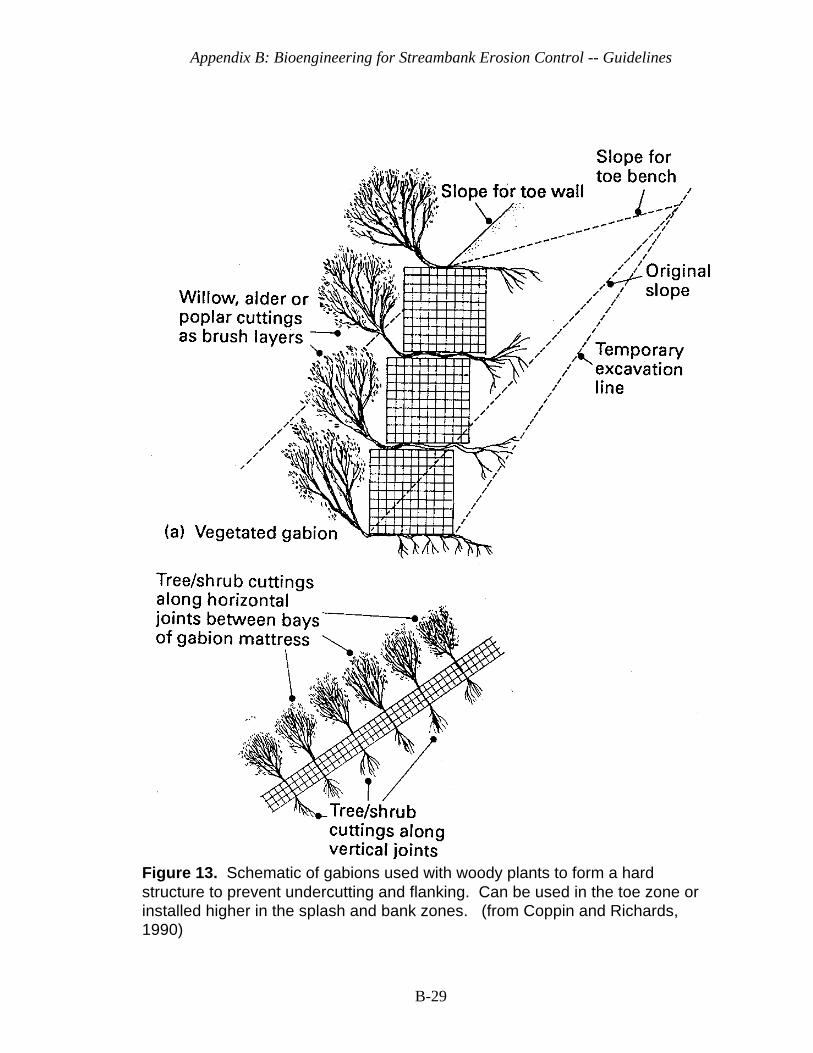
Appendix B: Bioengineering for Streambank Erosion Control -- Guidelines
B-29
Figure 13. Schematic of gabions used with woody plants to form a hardstructure to prevent undercutting and flanking. Can be used in the toe zone orinstalled higher in the splash and bank zones. (from Coppin and Richards,1990)
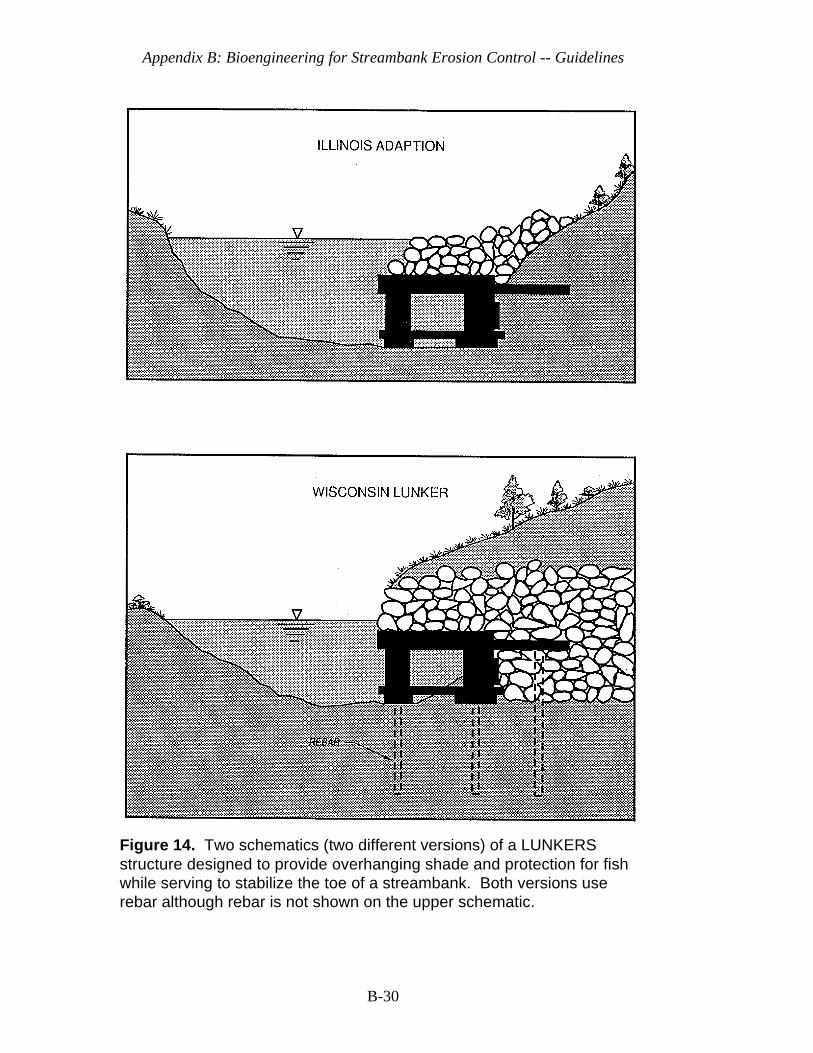
Appendix B: Bioengineering for Streambank Erosion Control -- Guidelines
B-30
Figure 14. Two schematics (two different versions) of a LUNKERSstructure designed to provide overhanging shade and protection for fishwhile serving to stabilize the toe of a streambank. Both versions userebar although rebar is not shown on the upper schematic.
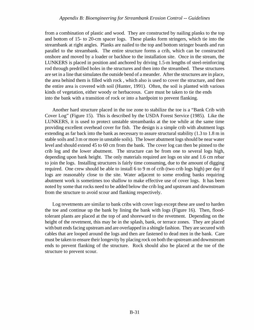
Appendix B: Bioengineering for Streambank Erosion Control -- Guidelines
B-31
from a combination of plastic and wood. They are constructed by nailing planks to the topand bottom of 15- to 20-cm spacer logs. These planks form stringers, which tie into thestreambank at right angles. Planks are nailed to the top and bottom stringer boards and runparallel to the streambank. The entire structure forms a crib, which can be constructedonshore and moved by a loader or backhoe to the installation site. Once in the stream, theLUNKERS is placed in position and anchored by driving 1.5-m lengths of steel-reinforcingrod through predrilled holes in the structures and then into the streambed. These structuresare set in a line that simulates the outside bend of a meander. After the structures are in place,the area behind them is filled with rock , which also is used to cover the structure, and thenthe entire area is covered with soil (Hunter, 1991). Often, the soil is planted with variouskinds of vegetation, either woody or herbaceous. Care must be taken to tie the endsinto the bank with a transition of rock or into a hardpoint to prevent flanking.
Another hard structure placed in the toe zone to stabilize the toe is a “Bank Crib withCover Log” (Figure 15). This is described by the USDA Forest Service (1985). Like theLUNKERS, it is used to protect unstable streambanks at the toe while at the same timeproviding excellent overhead cover for fish. The design is a simple crib with abutment logsextending as far back into the bank as necessary to assure structural stability (1.3 to 1.8 m instable soils and 3 m or more in unstable soils). The lower abutment logs should be near waterlevel and should extend 45 to 60 cm from the bank. The cover log can then be pinned to thecrib log and the lower abutment. The structure can be from one to several logs high,depending upon bank height. The only materials required are logs on site and 1.6 cm rebarto join the logs. Installing structures is fairly time consuming, due to the amount of diggingrequired. One crew should be able to install 6 to 9 m of crib (two crib logs high) per day iflogs are reasonably close to the site. Water adjacent to some eroding banks requiringabutment work is sometimes too shallow to make effective use of cover logs. It has beennoted by some that rocks need to be added below the crib log and upstream and downstreamfrom the structure to avoid scour and flanking respectively.
Log revetments are similar to bank cribs with cover logs except these are used to hardenthe toe and continue up the bank by lining the bank with logs (Figure 16). Then, flood-tolerant plants are placed at the top of and shoreward to the revetment. Depending on theheight of the revetment, this may be in the splash, bank, or terrace zones. They are placedwith butt ends facing upstream and are overlapped in a shingle fashion. They are secured withcables that are looped around the logs and then are fastened to dead men in the bank. Caremust be taken to ensure their longevity by placing rock on both the upstream and downstreamends to prevent flanking of the structure. Rock should also be placed at the toe of thestructure to prevent scour.
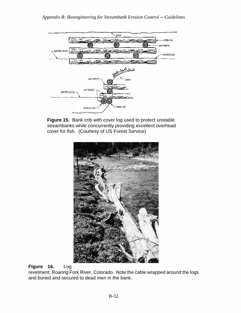
Appendix B: Bioengineering for Streambank Erosion Control -- Guidelines
B-32
Figure 15. Bank crib with cover log used to protect unstablestreambanks while concurrently providing excellent overheadcover for fish. (Courtesy of US Forest Service)
Figure 16. Logrevetment, Roaring Fork River, Colorado. Note the cable wrapped around the logsand buried and secured to dead men in the bank.

Appendix B: Bioengineering for Streambank Erosion Control -- Guidelines
B-33
Figure 17. Schematic of root wad construction (from Bowers, 1992).
Figure 17 shows a schematic of a log revetment used on the Roaring Fork River,Colorado, near Basalt. A geotextile coir roll, called a Vegetations-Faschinen in Germany,where it originated, is placed above the top log in the revetment so its top is just even withor slightly above the normal water level. The roll is often referred to in this country undervarious trade names such as Fiber Roll, Fiberschine, and Bio-log. It is used in conjunctionwith a geotextile mat which is placed shoreward of the roll, backfilled with soil, and plantedor seeded with wetland plants. The geotextile roll and mat trap sediment, allow plants to beplanted in them, and are biodegradable. Note that the top log is placed in an overhangingfashion with the coir roll on top to provide shade and cover for fish. Figure 18 shows aninstalled log revetment on the Roaring Fork River. Volume II presents a case study thatincludes evaluation of such a treatment, among others on western Colorado rivers andstreams and notes local velocities to which this treatment and others were subjected. On onereach of the Roaring Fork, this structure failed because it was not keyed into the bed of thestream. Scour at the toe caused structure failure. On another reach, it worked just fine.These structures must be properly protected at the toe and at the upper and lower ends withrock and hard points, respectively.

Appendix B: Bioengineering for Streambank Erosion Control -- Guidelines
B-34
Figure 18. Installed log revetment with coirgeotextile roll combination,Roaring Fork River, Colorado. Wetland vegetation is seeded orplanted in backfilled soil placedin a depression between therevetment and the land. Rock isplaced on top to prevent scour.
Root wads are live or dead logs with root masses attached (Figure 19, see Bowers, Landand Water, 1992). These are also used in the toe zone to protect it from undercutting, butmust be used in combination with other materials. The fans of the root wads provide aninterlocking wall protecting the streambank from erosion. The voids within and between theroot wads are filled with a soil mix and planted with live, willow clumps or root pads. Theroot wads are laid on top of a keyed-in shelf of stone and support logs. This shelf includesa layer of bottom support logs flush with one another, shingled together, and running parallelto the streambank. The root mass should be a minimum of 5-ft in diameter and angled slightlyupstream towards stream flow. This treatment should be placed at a base elevation that isconsistent with water levels during the major part of the growing season, i.e., June throughSeptember. The bottom two-thirds of the root wad should be in water during that period oftime. The upstream and downstream ends of the root wad treatment should be tied into hardpoints made from rock or some natural hard feature so as to prevent flanking.
Figure 20 shows a treatment using root wads on the Upper Truckee River in Californianear South Lake Tahoe, where this treatment and others were monitored for a couple ofgrowing seasons (see also Volume II). Various local flow velocities were measured along thetreatment on the fall of the hydrograph. These ranged from 1.6 to 4.0 fps at .6 depth of flowand 4 ft out from the right bank. The root wads sufficiently reduced local flow velocities sothat vegetation had a chance to get established and stabilize the bank despite a
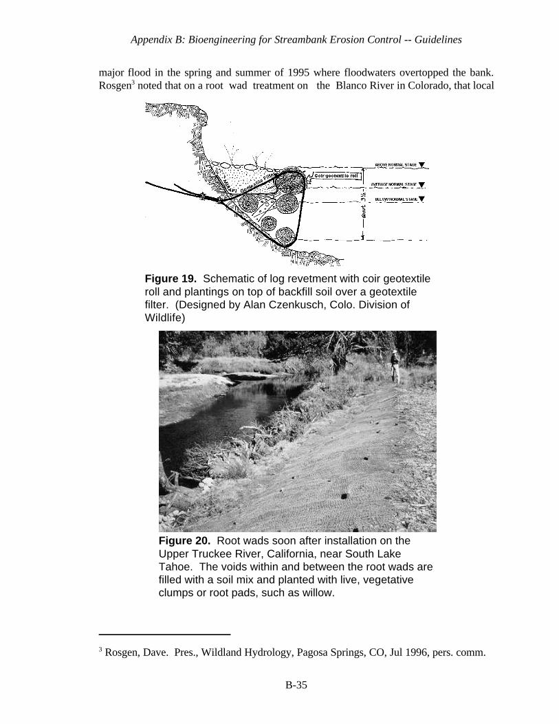
Appendix B: Bioengineering for Streambank Erosion Control -- Guidelines
3 Rosgen, Dave. Pres., Wildland Hydrology, Pagosa Springs, CO, Jul 1996, pers. comm.
B-35
Figure 19. Schematic of log revetment with coir geotextileroll and plantings on top of backfill soil over a geotextilefilter. (Designed by Alan Czenkusch, Colo. Division ofWildlife)
Figure 20. Root wads soon after installation on theUpper Truckee River, California, near South LakeTahoe. The voids within and between the root wads arefilled with a soil mix and planted with live, vegetativeclumps or root pads, such as willow.
major flood in the spring and summer of 1995 where floodwaters overtopped the bank.Rosgen3 noted that on a root wad treatment on the Blanco River in Colorado, that local
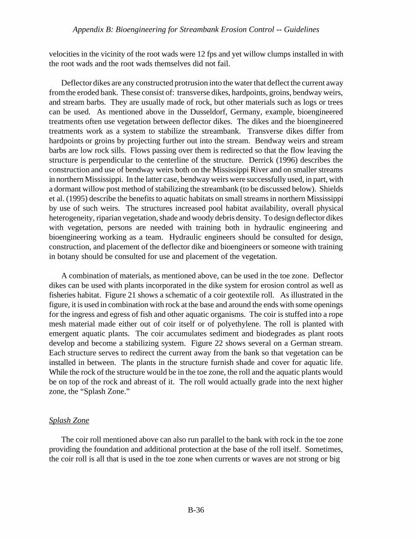
Appendix B: Bioengineering for Streambank Erosion Control -- Guidelines
B-36
velocities in the vicinity of the root wads were 12 fps and yet willow clumps installed in withthe root wads and the root wads themselves did not fail.
Deflector dikes are any constructed protrusion into the water that deflect the current awayfrom the eroded bank. These consist of: transverse dikes, hardpoints, groins, bendway weirs,and stream barbs. They are usually made of rock, but other materials such as logs or treescan be used. As mentioned above in the Dusseldorf, Germany, example, bioengineeredtreatments often use vegetation between deflector dikes. The dikes and the bioengineeredtreatments work as a system to stabilize the streambank. Transverse dikes differ fromhardpoints or groins by projecting further out into the stream. Bendway weirs and streambarbs are low rock sills. Flows passing over them is redirected so that the flow leaving thestructure is perpendicular to the centerline of the structure. Derrick (1996) describes theconstruction and use of bendway weirs both on the Mississippi River and on smaller streamsin northern Mississippi. In the latter case, bendway weirs were successfully used, in part, witha dormant willow post method of stabilizing the streambank (to be discussed below). Shieldset al. (1995) describe the benefits to aquatic habitats on small streams in northern Mississippiby use of such weirs. The structures increased pool habitat availability, overall physicalheterogeneity, riparian vegetation, shade and woody debris density. To design deflector dikeswith vegetation, persons are needed with training both in hydraulic engineering andbioengineering working as a team. Hydraulic engineers should be consulted for design,construction, and placement of the deflector dike and bioengineers or someone with trainingin botany should be consulted for use and placement of the vegetation.
A combination of materials, as mentioned above, can be used in the toe zone. Deflectordikes can be used with plants incorporated in the dike system for erosion control as well asfisheries habitat. Figure 21 shows a schematic of a coir geotextile roll. As illustrated in thefigure, it is used in combination with rock at the base and around the ends with some openingsfor the ingress and egress of fish and other aquatic organisms. The coir is stuffed into a ropemesh material made either out of coir itself or of polyethylene. The roll is planted withemergent aquatic plants. The coir accumulates sediment and biodegrades as plant rootsdevelop and become a stabilizing system. Figure 22 shows several on a German stream.Each structure serves to redirect the current away from the bank so that vegetation can beinstalled in between. The plants in the structure furnish shade and cover for aquatic life.While the rock of the structure would be in the toe zone, the roll and the aquatic plants wouldbe on top of the rock and abreast of it. The roll would actually grade into the next higherzone, the “Splash Zone.”
Splash Zone
The coir roll mentioned above can also run parallel to the bank with rock in the toe zoneproviding the foundation and additional protection at the base of the roll itself. Sometimes,the coir roll is all that is used in the toe zone when currents or waves are not strong or big
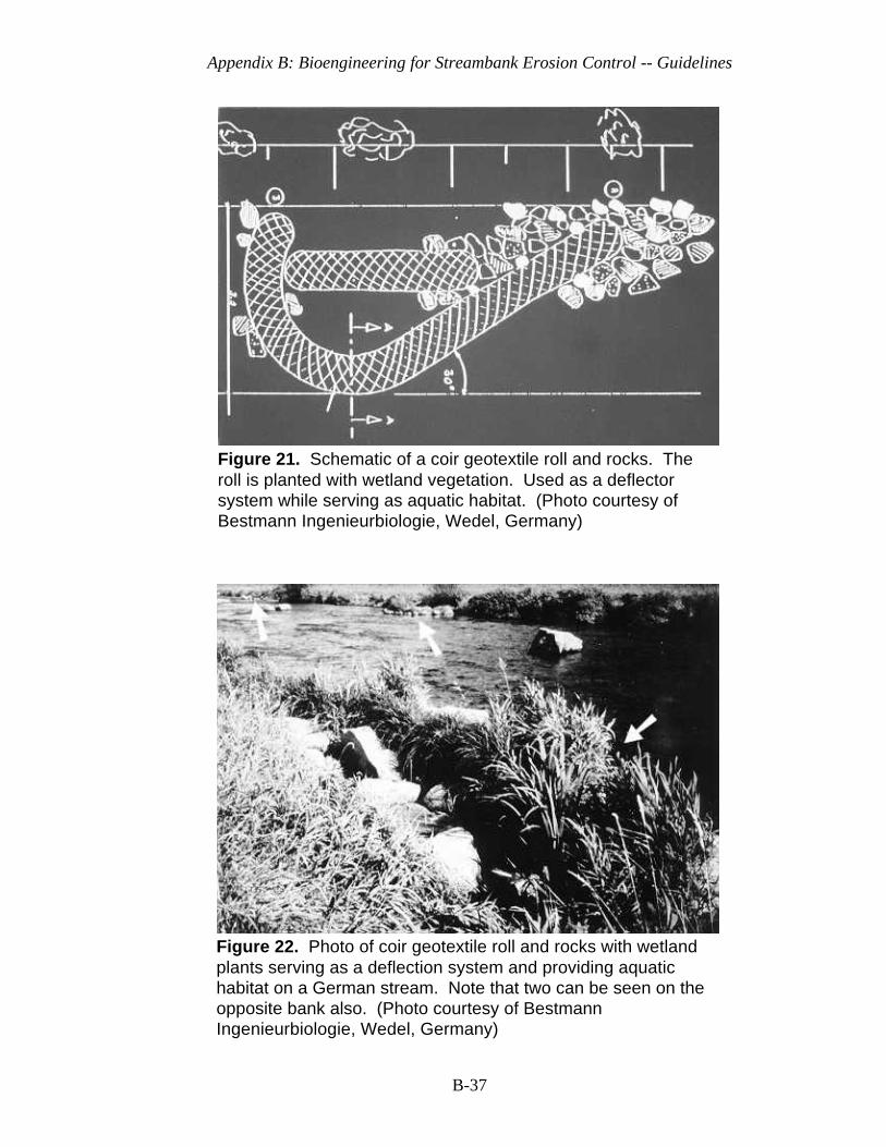
Appendix B: Bioengineering for Streambank Erosion Control -- Guidelines
B-37
Figure 21. Schematic of a coir geotextile roll and rocks. Theroll is planted with wetland vegetation. Used as a deflectorsystem while serving as aquatic habitat. (Photo courtesy ofBestmann Ingenieurbiologie, Wedel, Germany)
Figure 22. Photo of coir geotextile roll and rocks with wetlandplants serving as a deflection system and providing aquatichabitat on a German stream. Note that two can be seen on theopposite bank also. (Photo courtesy of BestmannIngenieurbiologie, Wedel, Germany)
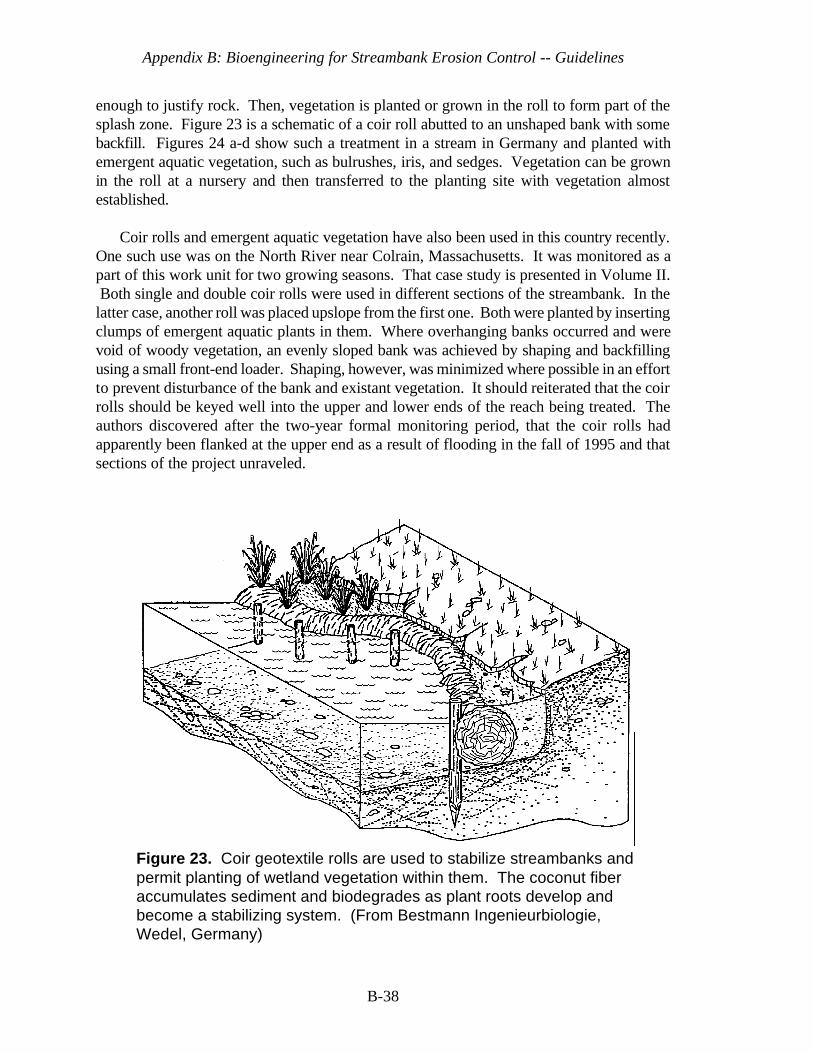
Appendix B: Bioengineering for Streambank Erosion Control -- Guidelines
B-38
Figure 23. Coir geotextile rolls are used to stabilize streambanks andpermit planting of wetland vegetation within them. The coconut fiberaccumulates sediment and biodegrades as plant roots develop andbecome a stabilizing system. (From Bestmann Ingenieurbiologie,Wedel, Germany)
enough to justify rock. Then, vegetation is planted or grown in the roll to form part of thesplash zone. Figure 23 is a schematic of a coir roll abutted to an unshaped bank with somebackfill. Figures 24 a-d show such a treatment in a stream in Germany and planted withemergent aquatic vegetation, such as bulrushes, iris, and sedges. Vegetation can be grownin the roll at a nursery and then transferred to the planting site with vegetation almostestablished.
Coir rolls and emergent aquatic vegetation have also been used in this country recently.One such use was on the North River near Colrain, Massachusetts. It was monitored as apart of this work unit for two growing seasons. That case study is presented in Volume II. Both single and double coir rolls were used in different sections of the streambank. In thelatter case, another roll was placed upslope from the first one. Both were planted by insertingclumps of emergent aquatic plants in them. Where overhanging banks occurred and werevoid of woody vegetation, an evenly sloped bank was achieved by shaping and backfillingusing a small front-end loader. Shaping, however, was minimized where possible in an effortto prevent disturbance of the bank and existant vegetation. It should reiterated that the coirrolls should be keyed well into the upper and lower ends of the reach being treated. Theauthors discovered after the two-year formal monitoring period, that the coir rolls hadapparently been flanked at the upper end as a result of flooding in the fall of 1995 and thatsections of the project unraveled.
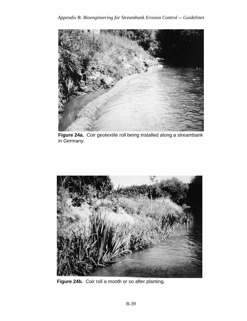
Appendix B: Bioengineering for Streambank Erosion Control -- Guidelines
B-39
Figure 24b. Coir roll a month or so after planting.
Figure 24a. Coir geotextile roll being installed along a streambankin Germany.

Appendix B: Bioengineering for Streambank Erosion Control -- Guidelines
B-40
Figure 24d. Closer view of coir roll a few months after plantestablishment.
Figure 24c. Coir roll a few months later.
Figure24. Wetland plant development in a coir geotextile roll within the splashzone at a stream in Germany. (Photos of Figures 24 a-d courtesy of BestmannIngenieurbiologie, Wedel, Germany)

Appendix B: Bioengineering for Streambank Erosion Control -- Guidelines
B-41
The clumps of emergent aquatic plants mentioned above that were placed in the coir rollswere grown from seedlings placed in a coir wrapping and allowed to develop hydroponically(in water without soil, but with nutrients added). This leads to a well-developed, but light andeasily transportable plant unit with roots readily established and poised to grow in a plantingmedium, such as the coir roll or in a soil substrate.
Coir fiber mats made in various thicknesses are also used in the splash zone. These areoften prevegetated at the nursery with emergent aquatic plants (Figure 25 a-c) or sometimessprigged (use of single or multiple rooted stems inserted into substrate) with emergent aquaticplants harvested from local sources. When prevegetated at the nursery, the fiber mats havethe advantage of being light and can be lifted in rolls or smaller mats and transferred directlyto the planting site where immediate establishment is required. They are usually tied into orkeyed into whatever is used as the toe material. In the example on the North River above,1-inch thick mats were prevegetated and tied into the coir rolls. Coir fiber mats have theattributes of high tensile strengths, the ability to trap sediment, they are pH neutral, theyfacilitate root development because of the fiber network, and they are slow to biodegrade.These types of vegetated coir mats have also been used on dredged material in coastalenvironments with wave environments. Knutson et al. (1990) reported successful trials ofsprigging emergent aquatic plants into such mats. This success was attributed, in part, to theattributes mentioned above, such as sediment entrapment. The blankets trapped sedimentvery well on the North River which aided plant establishment.
Single-stemmed sprigs and clumps of emergent aquatic plants and flood-tolerant grassesor grass-like plants, e.g., rushes, sedges, can be planted shoreward of hard rock toes, coirrolls, and fiber mats. They can even be used in lieu of the fiber mats if the site-specificconditions are appropriate. This may mean that the soils are more cohesive, i.e., have moreclay in them, the stream discharges at that level are not as high.
Our focus in the splash zone, so far, has been on use of emergent aquatic and otherherbaceous plants. Woody plants are also used in the splash zone. For these, wetland plantsare used that can also withstand periods of dryness. The woody plants should be those thatcan sprout roots and branches from the stem. These include willow, some species of alder,dogwood, and several other species. Several possible species are listed by the Georgia Soiland Water Conservation Commission (1994) and Gray and Sotir (1996). Sometimes, woodyplants may be all that are suited to the splash zone. At times, the bank geometry is very steepdown to the normal flow level without a shallow water zone for emergent aquatics or, thestream system has extreme fluctuations and large silt loads that would drop sediment onemergent aquatics and bury them.
Bioengineering techniques that utilize woody plants include: brushmattress, brushlayering, vegetative geogrids, dormant post method, dormant cuttings, and dormant rootpads. All of these are usually used in combination with hard structures or materials that eitherdeflect the current away from the bank or protect the toe and upper and lower ends.

Appendix B: Bioengineering for Streambank Erosion Control -- Guidelines
B-42
Figure 25a. Emergent aquatic plants in WES greenhousenursery that were seeded on coir fiber mat.
Figure 25b. Emergent aquatic plants established on a coirfiber mat being rolled up in the WES nursery ready for transportto the bioengineering site.

Appendix B: Bioengineering for Streambank Erosion Control -- Guidelines
B-43
Figure 25c. Coir geotextile mat in a roll planted with emergentaquatic plants being carried to the planting site.
Figure 25. Coir geotextile mat being prevegetated in the nursery and transportedto the field site ready for immediate growth. Roots and stems of the plant havealready been established in the mat.
For instance, dormant root pads are used with root wads that were discussed above for thetoe zone.
Brushmattress. A brushmattress, sometimes called brush matting or a brush barrier, is acombination of a thick layer (mattress) of interlaced live willow switches or branches andwattling. Both are held in place by wire and stakes. The branches in the mattress are usuallyabout 2 to 3 years old, sometimes older, and 1.5 to 3 m long. Basal ends are usually not morethan about 3.5 cm in diameter. They are placed perpendicular to the bank with their basalends inserted into a trench at the bottom of the slope in the splash zone, just above any toeprotection, such as a rock toe. The branches are cut from live willow plants and kept moistuntil planting. The willow branches will sprout after planting, but care should be taken toobtain and plant them in the dormant period, either in the late fall after bud set or in the earlyspring before bud break. A compacted layer of branches 10 to 15 cm thick is used and is heldin place by either woven wire or tie-wire. Wedge-shaped construction stakes (2 X 4 X 24 “to 2 X 4 X 36", diagonal cut) are used to hold the wire in place. A guage and type suitablefor tie-wire is No. 9 or 10 galvanized annealed. It is run perpendicular to the branches andalso diagonally from stake to stake and usually tied by use of a clove-hitch. If woven wireis used, it should be a strong welded wire (2- by 4-in mesh). The wedged-shape stakes aredriven firmly through the wire as it is stretched over the mattress to hold it in place. The
Appendix B: Bioengineering for Streambank Erosion Control -- Guidelines
B-44
wedge of the stake actually compresses the wire to hold the brush down. Wattling is a cigar-shaped bundle of live, shrubby material made from species that root very quickly from thestem, such as willow and some species of dogwood and alder. These bundles are laid overthe basal ends of the brushmattress material that was placed in the ditch and staked. Theprocedure of making wattling bundles and installing them over the brushmattress material ispresented in more detail below (These procedures are modified after Leiser (1994).
Wattling bundles may vary in length, depending on materials available. Bundles taper atthe ends and this is achieved by alternately (randomly) placing each stem so that about one-half of the basal ends are at each end of the bundle. When compressed firmly and tied, eachbundle is about 15 to 20-cm in diameter in the middle. Bundles should be tied with eitherhemp binder twine or can be fastened and compressed by wrapping “pigtails” around thebundle. Pigtails are commonly used to fasten rebar together. If tied with binder twine, aminimum of two wraps should be used in combination with a non-slipping knot, such as asquare knot. Tying of bundles should be done on about 38-cm centers. Wattling bundlesshould be staked firmly in place with vertical stakes on the downhill side of the wattling notmore than 90 cm on center and with the wedge of the stake pointing upslope. Also, stakesshould be installed through the bundles at about the same distance, but slightly off-set andturned around so their wedge points downslope. In this way, the wedged stakes, in tandem,compress the wattling very firmly. Where bundles overlap, an additional pair of stakes shouldbe used at the midpoint of the overlap. The overlap should be staked with one pair of stakesthrough the ends of both bundles while on the inside of the end tie of each bundle. Figures26 a-b show a schematic of a brushmattress and wattling. Figures 27 a-c show a sequenceof installing a brushmattress with wattling at a workshop. It should be noted that because ofthe workshop setting at a mild time of the year, non-dormant vegetative material is beingused. Normally, one would preferably use dormant material.
Both brushmattress and wattling should be covered immediately with soil and tamped.Soil should be worked into both the brushmattress and wattling by by both tamping andwalking on it. All but the edges of the brushmattress should be covered with soil and about75 percent of the wattling should be covered leaving some of each exposed to facilitatesprouting of stems rather than roots.
A brushmattress without any rock toe was used on the North River, Massachusetts, andperformed quite well for two growing seasons until unraveling started to occur, again becauseof a lack of toe and upper and lower end protection. This was in a reach where a bankfull discharge was experienced with an associated average bankfull velocity
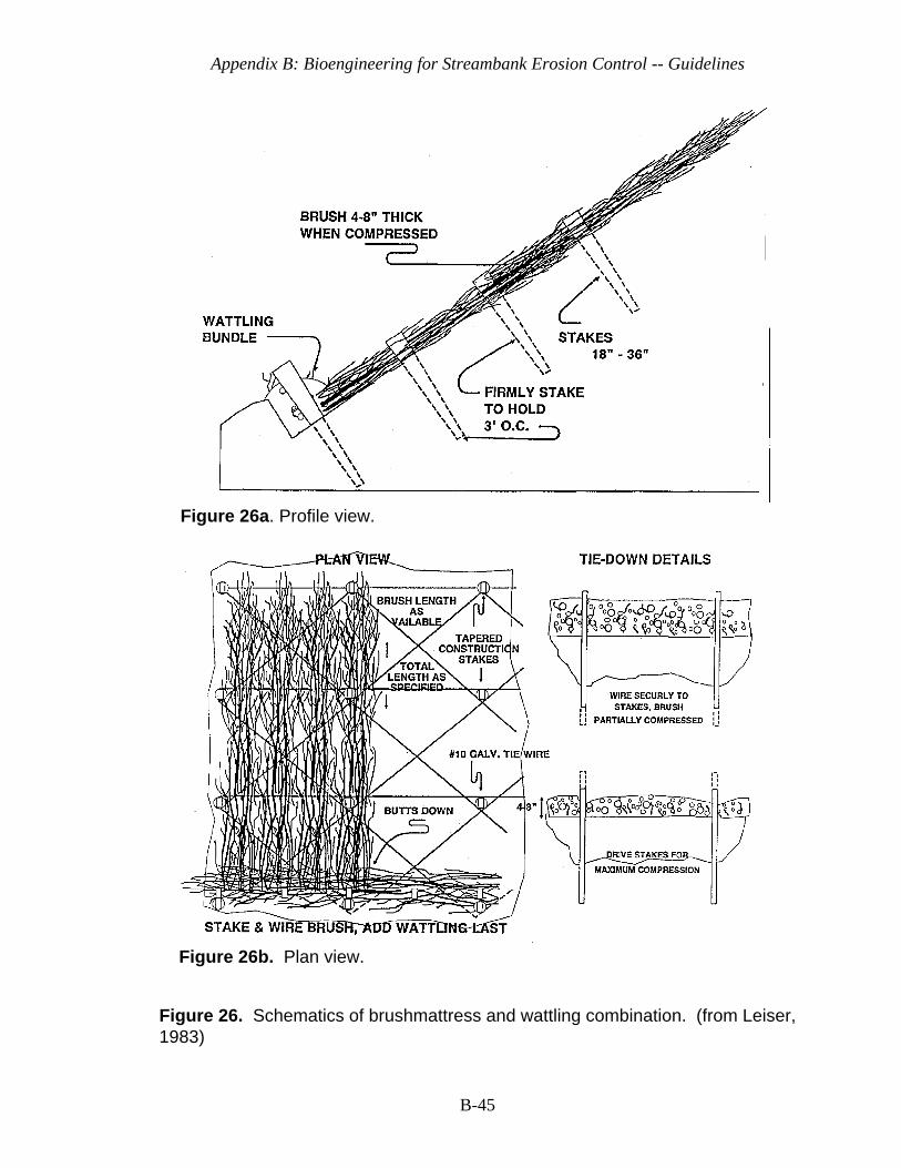
Appendix B: Bioengineering for Streambank Erosion Control -- Guidelines
B-45
Figure 26b. Plan view.
Figure 26a. Profile view.
Figure 26. Schematics of brushmattress and wattling combination. (from Leiser,1983)
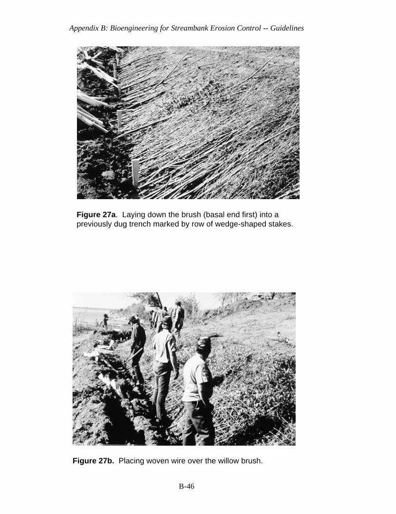
Appendix B: Bioengineering for Streambank Erosion Control -- Guidelines
B-46
Figure 27a. Laying down the brush (basal end first) into apreviously dug trench marked by row of wedge-shaped stakes.
Figure 27b. Placing woven wire over the willow brush.
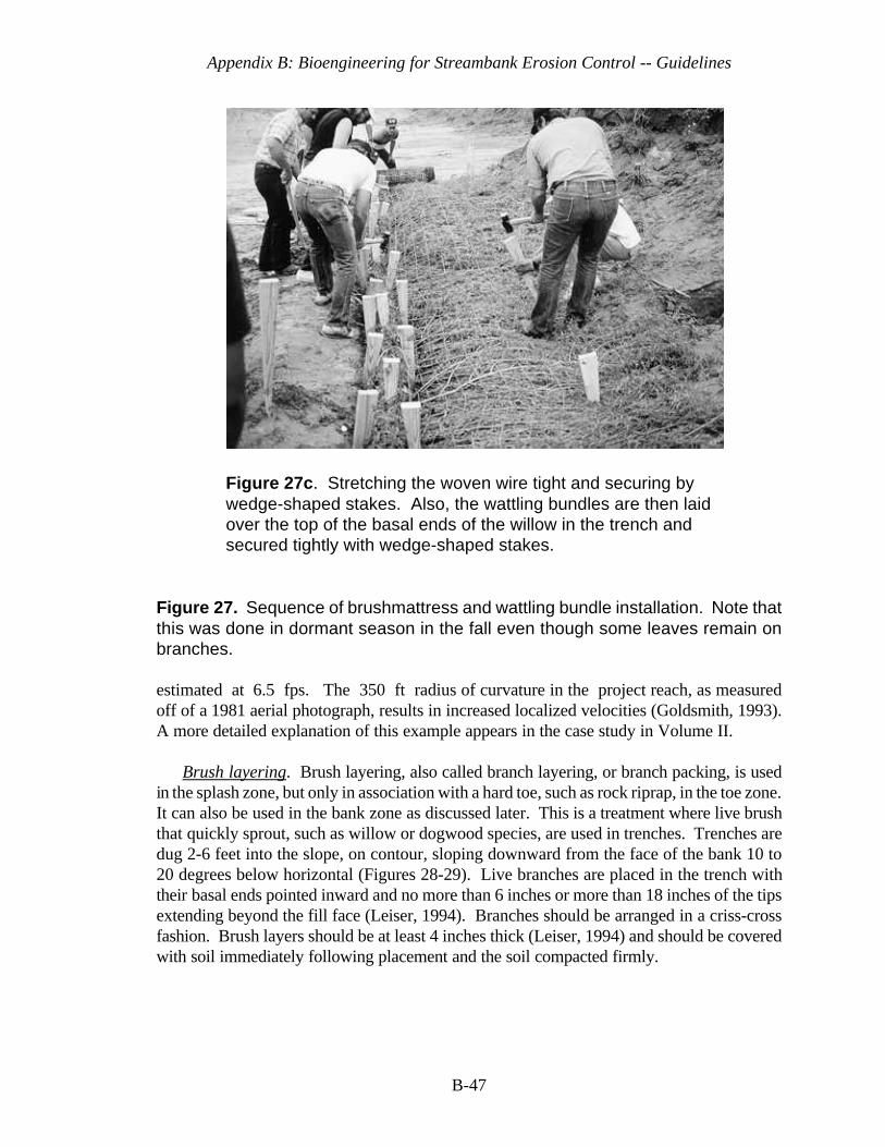
Appendix B: Bioengineering for Streambank Erosion Control -- Guidelines
B-47
Figure 27c. Stretching the woven wire tight and securing bywedge-shaped stakes. Also, the wattling bundles are then laidover the top of the basal ends of the willow in the trench andsecured tightly with wedge-shaped stakes.
Figure 27. Sequence of brushmattress and wattling bundle installation. Note thatthis was done in dormant season in the fall even though some leaves remain onbranches.
estimated at 6.5 fps. The 350 ft radius of curvature in the project reach, as measuredoff of a 1981 aerial photograph, results in increased localized velocities (Goldsmith, 1993).A more detailed explanation of this example appears in the case study in Volume II.
Brush layering. Brush layering, also called branch layering, or branch packing, is usedin the splash zone, but only in association with a hard toe, such as rock riprap, in the toe zone.It can also be used in the bank zone as discussed later. This is a treatment where live brushthat quickly sprout, such as willow or dogwood species, are used in trenches. Trenches aredug 2-6 feet into the slope, on contour, sloping downward from the face of the bank 10 to20 degrees below horizontal (Figures 28-29). Live branches are placed in the trench withtheir basal ends pointed inward and no more than 6 inches or more than 18 inches of the tipsextending beyond the fill face (Leiser, 1994). Branches should be arranged in a criss-crossfashion. Brush layers should be at least 4 inches thick (Leiser, 1994) and should be coveredwith soil immediately following placement and the soil compacted firmly.
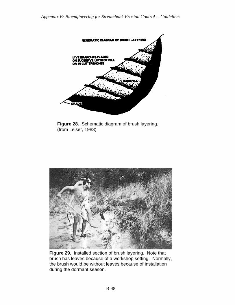
Appendix B: Bioengineering for Streambank Erosion Control -- Guidelines
B-48
Figure 28. Schematic diagram of brush layering.(from Leiser, 1983)
Figure 29. Installed section of brush layering. Note thatbrush has leaves because of a workshop setting. Normally,the brush would be without leaves because of installationduring the dormant season.
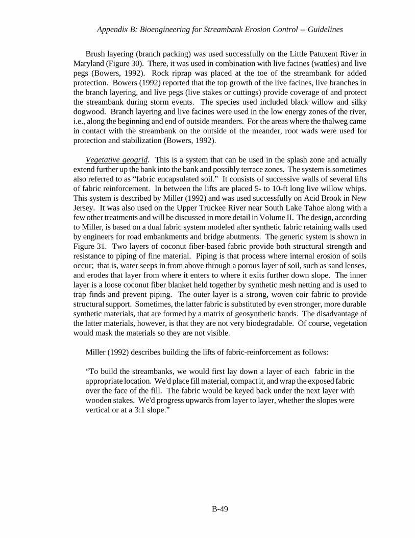
Appendix B: Bioengineering for Streambank Erosion Control -- Guidelines
B-49
Brush layering (branch packing) was used successfully on the Little Patuxent River inMaryland (Figure 30). There, it was used in combination with live facines (wattles) and livepegs (Bowers, 1992). Rock riprap was placed at the toe of the streambank for addedprotection. Bowers (1992) reported that the top growth of the live facines, live branches inthe branch layering, and live pegs (live stakes or cuttings) provide coverage of and protectthe streambank during storm events. The species used included black willow and silkydogwood. Branch layering and live facines were used in the low energy zones of the river,i.e., along the beginning and end of outside meanders. For the areas where the thalweg camein contact with the streambank on the outside of the meander, root wads were used forprotection and stabilization (Bowers, 1992).
Vegetative geogrid. This is a system that can be used in the splash zone and actuallyextend further up the bank into the bank and possibly terrace zones. The system is sometimesalso referred to as “fabric encapsulated soil.” It consists of successive walls of several liftsof fabric reinforcement. In between the lifts are placed 5- to 10-ft long live willow whips.This system is described by Miller (1992) and was used successfully on Acid Brook in NewJersey. It was also used on the Upper Truckee River near South Lake Tahoe along with afew other treatments and will be discussed in more detail in Volume II. The design, accordingto Miller, is based on a dual fabric system modeled after synthetic fabric retaining walls usedby engineers for road embankments and bridge abutments. The generic system is shown inFigure 31. Two layers of coconut fiber-based fabric provide both structural strength andresistance to piping of fine material. Piping is that process where internal erosion of soilsoccur; that is, water seeps in from above through a porous layer of soil, such as sand lenses,and erodes that layer from where it enters to where it exits further down slope. The innerlayer is a loose coconut fiber blanket held together by synthetic mesh netting and is used totrap finds and prevent piping. The outer layer is a strong, woven coir fabric to providestructural support. Sometimes, the latter fabric is substituted by even stronger, more durablesynthetic materials, that are formed by a matrix of geosynthetic bands. The disadvantage ofthe latter materials, however, is that they are not very biodegradable. Of course, vegetationwould mask the materials so they are not visible.
Miller (1992) describes building the lifts of fabric-reinforcement as follows:
“To build the streambanks, we would first lay down a layer of each fabric in theappropriate location. We'd place fill material, compact it, and wrap the exposed fabricover the face of the fill. The fabric would be keyed back under the next layer withwooden stakes. We'd progress upwards from layer to layer, whether the slopes werevertical or at a 3:1 slope.”
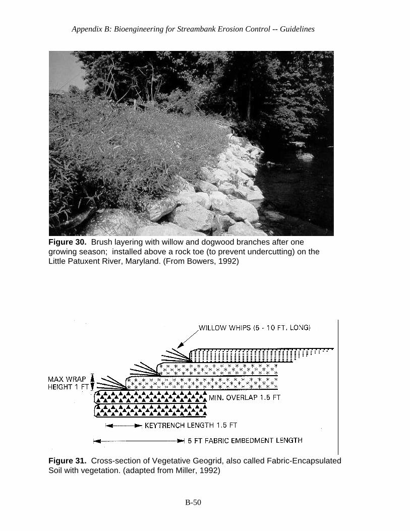
Appendix B: Bioengineering for Streambank Erosion Control -- Guidelines
B-50
Figure 30. Brush layering with willow and dogwood branches after onegrowing season; installed above a rock toe (to prevent undercutting) on theLittle Patuxent River, Maryland. (From Bowers, 1992)
Figure 31. Cross-section of Vegetative Geogrid, also called Fabric-EncapsulatedSoil with vegetation. (adapted from Miller, 1992)
Appendix B: Bioengineering for Streambank Erosion Control -- Guidelines
4Matt Kiese, Interfluve Inc., October 1993, personal communication
B-51
Figures 32 and 33 show photographs of the Upper Truckee River site both before andafter construction. The latter figure was taken in July 1995 after an extended high flowperiod from May 21 through July 21. There, Mr. Matt Kiese4 (pers. communication)described building the lifts with the use of long angle iron forms. The angle irons were 8 ftlong and were fashioned to form a frame into which plywood boards were inserted. Then,the forms were wrapped with two fabrics similar to those described above and soil dumpedinto the forms and compacted. The fabrics were wrapped back over the soil and the formsremoved. Willow whips were laid on top of each lift and then the next lift was prepared. Theinstallation at the Upper Truckee was no more than five feet tall and 123 ft long. Care mustbe taken to provide rock or some other hard material at each upstream and downstream endto prevent flanking of the treatment. For instance, one may either tie into existing vegetation,such as trees, or create hard ends by placing rock. Also, it is important to prevent scour atthe bottom lift and to provide a good footing by creating a ditch and filling it with cobble orrock. The first lift is placed on top of the cobble ditch. The ditch at the Upper Truckee Riversite was about 2-ft wide by 2-ft deep.
This treatment was very successful on the Upper Truckee River despite the 5-yr floodevent in May 1995 that produced overbank flows. The treatment remained in place sincesince October 1993. Further discussion about this treatment can be found in Volume II.
Dormant Post Method. This treatment consists of placing in the splash zone and perhapsthe lower part of the bank zone dormant, but living stems of woody species that sprout stemsand roots from the stem, such as willow or cottonwood. Willows are normally used and arecut into 10-14 ft posts when the leaves have fallen and the tree is dormant. The dormantposts store root hormones and food reserves (carbohydrates) that promote sprouting of stemsand roots during the growing season. According to Roseboom (1993), dense stands of 4-6year old willows make the best harvesting areas. He also uses posts that are 4-6 inches indiameter at the base. His examples are based on fast-growing eastern species, however, andsmaller willow may have to be used in the western states.
Roseboom (1993) prescribes shaping a bank to a 1:1 slope with the spoil placed in a 6-inch deep layer along the top of the bank. In major erosion sites, post holes are formed in thebed and bank so that the end of the post is 2 ft below maximum streambed scour (that portionof the streambed that is subject to movement). Hoag (1993) suggested that for bankstabilization, the cutting (post) should extend 2-3 ft above ground so as it leafs out, it canprovide immediate bank erosion protection. He also recommended the cutting should beplanted as much as 3-5 feet into the ground. If they are not this deep, moving water canerode around the cutting and rip it out of the ground. Roseboom places the posts four feetapart up the streambank. The posts in one row are offset from the posts in adjacent rows.

Appendix B: Bioengineering for Streambank Erosion Control -- Guidelines
B-52
Figure 32. Vegetative geogrid during construction on the UpperTruckee River, California, near South Lake Tahoe. Note rocktoe that was keyed into channel bed and bank to preventundercutting. Photo was taken in October 1993.
Figure 33. Vegetative geogrid in July 1995, after two growingseasons and an estimated 5-yr flood during the spring of 1995. Note that live willow whips which were placed between thelayers of COIR fabric are sprouting and spreading. (Photocourtesy of Ms. Catherine McDonald, Calif. State Parks)
Appendix B: Bioengineering for Streambank Erosion Control -- Guidelines
B-53
Both Roseboom (1993) and Hoag (1993) advised that willow posts should be longenough and placed deep enough to reach wet soil during dry summers. Hoag (1993) notedthat plantings can occur at the water line, up the bank, and on top of bank in relatively drysoil, as long as cuttings are long enough to reach into the mid-summer water table.
An excavator that is either fitted with a long, steel ram or an auger is typically requiredfor installation. Roseboom (1993) reported that a steel ram on an excavator boom is moreefficient at depths of 6 feet in clay soils. In contrast, an auger on an excavator boom formsdeeper and longer lasting holes in stoney or sandy streambeds. The ram on the excavator isfor creating a pilot hole in which to place the willow post. The willow post is fitted with acap that goes over the post and then the heel of the bucket on the excavator is used to pushthe post down into the hole. Care must be taken to ensure that the post comes in contact withthe soil so that no air pockets exist. In the case of the auger, this can be done by backfillingthe sides of the hole in lifts and then tamping. In the case of the ram, the ram can be placedout a few inches from the post and run along the side of it into the soil so as to close the holecontaining the post, especially toward the bottom of the hole.
Roseboom (1993) reported that in larger streams with non-cohesive sand banks, largecedar trees cabled to the willow posts along the toe of the bank can reduce toe erosion. Thecedars not only reduce bank scour while root systems are growing, but retain moisture duringdrought periods. Another material used for the same purpose is a coir roll mentioned earlier.In addition to trapping sediment, the coir roll can be planted with either emergent aquaticvegetation or other willow cuttings. The cedar trees and the coir roll were used incombination with willow poles on Court Creek, Illinois, along a 600-ft reach. Figures 34 and35 respectively illustrate work in progress and bank conditions four months after planting.This is described in a case study in Volume II. Velocities were measured at this site duringa major 1995 flood and ranged between 1.23 to 3.11 fps. They were measured at distancesimmediately in front of the treatment to 3.5 ft in front and at both the surface and 0.6 d. Itis suspected that the willow contributed substantially to reduced velocities near the bank.
Hoag (1994a) and Hoag (1994b) provided specifications for and description of anothertype of implement that is used to make a pilot hole for the dormant willow post. It is called“The Stinger” and has been used by the USDA Natural Resources Conservation Service(NRCS) and the Bureau of Reclamation for establishing willow in riprapped revetments onshorelines of reservoirs and streambanks. According to Hoag (1994b), woody vegetation hasbeen planted in rock rip-rap in the past, but the methods have concentrated on planting thecuttings first and dumping rock on top of them or planting through the rock riprap with asteel bar or water jet (Hoag 1994b cites Schultze and Wilcox 1985).
Hoag (1994b) states: “Neither of these methods are very efficient nor have achieved greatsuccess. 'The Stinger', however, builds upon these methods and utilizes the power of abackhoe to plant much bigger diameter and much longer cuttings than was possible before.“The Stinger” can plant cuttings right through rock riprap with minimal effort to betterstabilize the rock, allow the cutting to be above the ice layer, and to improve the aesthetics

Appendix B: Bioengineering for Streambank Erosion Control -- Guidelines
B-54
Figure 34. Dormant willow posts, coir geotextile roll, and cedartrees being installed at Court Creek, Illinois, April 1993. (Photocourtesy of Mr. Donald Roseboom, Illinois State Water Survey)
Figure 35. Court Creek site above after one growing season. Note that this is after one major flood in spring and summer,1994, that overtopped the banks. (Photo courtesy of Mr. DonaldRoseboom, Illinois State Water Survey)
of the riprap.” “The Stinger” can plant through 2 to 3-ft riprap, but it must penetrate themoist soil below in which to push the dormant willow pole.”
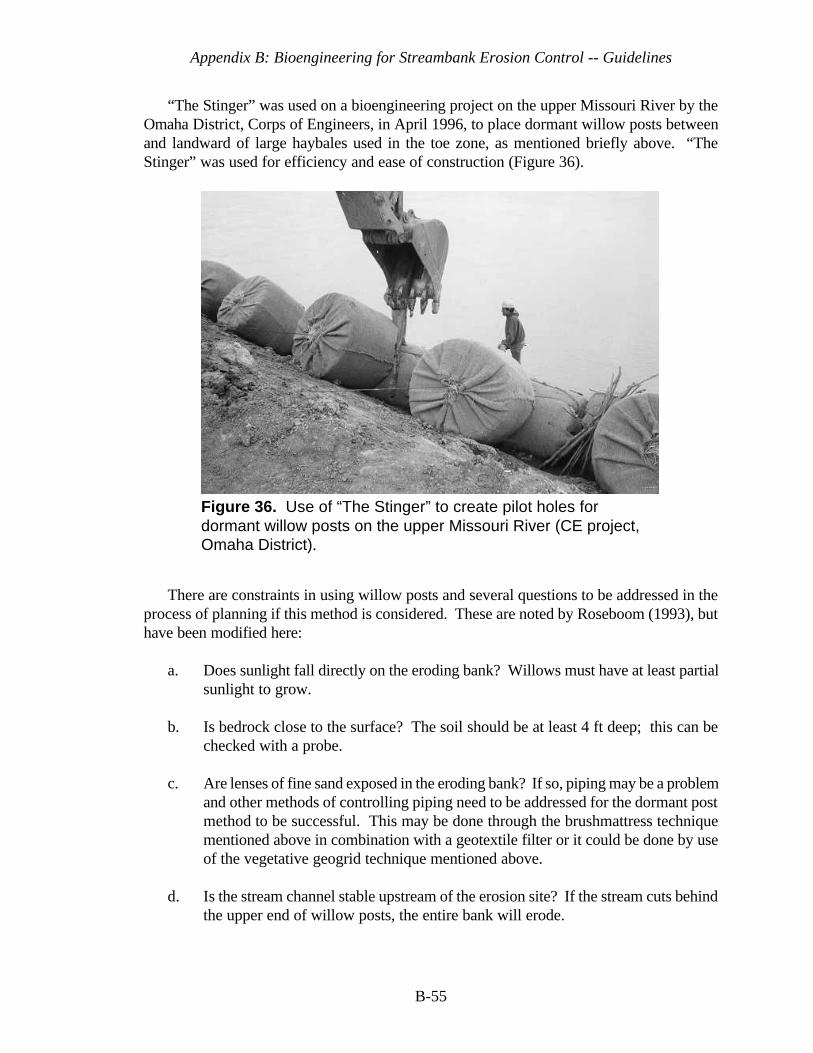
Appendix B: Bioengineering for Streambank Erosion Control -- Guidelines
B-55
Figure 36. Use of “The Stinger” to create pilot holes fordormant willow posts on the upper Missouri River (CE project,Omaha District).
“The Stinger” was used on a bioengineering project on the upper Missouri River by theOmaha District, Corps of Engineers, in April 1996, to place dormant willow posts betweenand landward of large haybales used in the toe zone, as mentioned briefly above. “TheStinger” was used for efficiency and ease of construction (Figure 36).
There are constraints in using willow posts and several questions to be addressed in theprocess of planning if this method is considered. These are noted by Roseboom (1993), buthave been modified here:
a. Does sunlight fall directly on the eroding bank? Willows must have at least partialsunlight to grow.
b. Is bedrock close to the surface? The soil should be at least 4 ft deep; this can bechecked with a probe.
c. Are lenses of fine sand exposed in the eroding bank? If so, piping may be a problemand other methods of controlling piping need to be addressed for the dormant postmethod to be successful. This may be done through the brushmattress techniquementioned above in combination with a geotextile filter or it could be done by useof the vegetative geogrid technique mentioned above.
d. Is the stream channel stable upstream of the erosion site? If the stream cuts behindthe upper end of willow posts, the entire bank will erode.
Appendix B: Bioengineering for Streambank Erosion Control -- Guidelines
B-56
e. How deep is the stream along the eroding bank? Willow posts must penetrate toa depth that is deeper than the water near the eroding bank. There should be a shelfor at least a sloping bank that allows willow posts to penetrate at least 2 feet deeperthan the deepest water at the shore or the posts will be undercut below the rootzone. If this cannot be achieved by the willow posts, then some kind of hard toe,like a rock revetment, should be used to prevent scour beneath the posts. Thelength of the willow posts will depend on the water depth as well as the dryness ofthe soil above the stream level.
f. How wide is the stream channel at the erosion sites when compared to stablechannels upstream and downstream? The channel with vegetation at the erosionsite(s) should not be narrower than stable channels upstream or downstream;otherwise, vegetation could choke the channel and cause other erosion problems.
g. Do you have a source of large willows close to the site? Costs are less when willowstands are close because of less transportation costs. Also, there is less chance ofmortality due to long durations of handling and possible drying of the willow.
h. Will the site be wet during dry summers? Willow posts require considerable waterwhile the roots are becoming established from the root primordia on the stems. Fordry sites, such as in the western states of the United States, tops of willow postsshould be only 1-2 feet above ground and they should penetrate into at least thecapillary zone of the groundwater table. Figure 10 shows willow posts being usedin eastern Montana on the upper Missouri River in combination with a line of coir-covered haybales for toe protection. In similar cases, care should be taken to ensurethe posts are cut off not more than two feet above ground and that they penetratethe groundwater.
i. Can you keep cattle and other animals, domestic or wild, away from the posts
during the first summer? Willows and other plants produce food for regrowth fromleaf photosynthesis. If these sprouting branches with leaves continue to be browsedor if the tops of the plants continue to be cut off by beaver during the first growingseason, they could die. It is best to prevent this by keeping cattle off of the area andeither trap beaver off the area or spray the willow stems with organic beaverdeterrent sprays, made with such constituents as mountain lion urine. It should benoted, however, that beaver damage during subsequent years of development mayonly promote resprouting of branches from the main stem and actually promote ashrubby-like plant. This is a positive effect from a surface roughness perspectivewhereas the many branches slow the current and promote sedimentation that canlead to other plant colonization.
j. Have debris jams or trees and logs forced floodwater into the eroding bank? Thesemust be removed at least to the point where they are not directing water into abank. Trees and logs can be moved parallel to the bank and cabled to dead men.
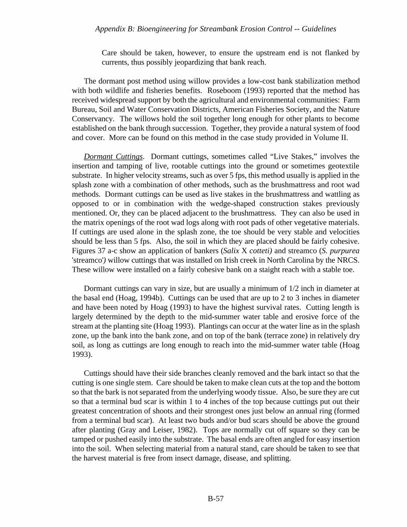
Appendix B: Bioengineering for Streambank Erosion Control -- Guidelines
B-57
Care should be taken, however, to ensure the upstream end is not flanked bycurrents, thus possibly jeopardizing that bank reach.
The dormant post method using willow provides a low-cost bank stabilization methodwith both wildlife and fisheries benefits. Roseboom (1993) reported that the method hasreceived widespread support by both the agricultural and environmental communities: FarmBureau, Soil and Water Conservation Districts, American Fisheries Society, and the NatureConservancy. The willows hold the soil together long enough for other plants to becomeestablished on the bank through succession. Together, they provide a natural system of foodand cover. More can be found on this method in the case study provided in Volume II.
Dormant Cuttings. Dormant cuttings, sometimes called “Live Stakes,” involves theinsertion and tamping of live, rootable cuttings into the ground or sometimes geotextilesubstrate. In higher velocity streams, such as over 5 fps, this method usually is applied in thesplash zone with a combination of other methods, such as the brushmattress and root wadmethods. Dormant cuttings can be used as live stakes in the brushmattress and wattling asopposed to or in combination with the wedge-shaped construction stakes previouslymentioned. Or, they can be placed adjacent to the brushmattress. They can also be used inthe matrix openings of the root wad logs along with root pads of other vegetative materials.If cuttings are used alone in the splash zone, the toe should be very stable and velocitiesshould be less than 5 fps. Also, the soil in which they are placed should be fairly cohesive.Figures 37 a-c show an application of bankers (Salix X cotteti) and streamco (S. purpurea'streamco') willow cuttings that was installed on Irish creek in North Carolina by the NRCS.These willow were installed on a fairly cohesive bank on a staight reach with a stable toe.
Dormant cuttings can vary in size, but are usually a minimum of 1/2 inch in diameter atthe basal end (Hoag, 1994b). Cuttings can be used that are up to 2 to 3 inches in diameterand have been noted by Hoag (1993) to have the highest survival rates. Cutting length islargely determined by the depth to the mid-summer water table and erosive force of thestream at the planting site (Hoag 1993). Plantings can occur at the water line as in the splashzone, up the bank into the bank zone, and on top of the bank (terrace zone) in relatively drysoil, as long as cuttings are long enough to reach into the mid-summer water table (Hoag1993).
Cuttings should have their side branches cleanly removed and the bark intact so that thecutting is one single stem. Care should be taken to make clean cuts at the top and the bottomso that the bark is not separated from the underlying woody tissue. Also, be sure they are cutso that a terminal bud scar is within 1 to 4 inches of the top because cuttings put out theirgreatest concentration of shoots and their strongest ones just below an annual ring (formedfrom a terminal bud scar). At least two buds and/or bud scars should be above the groundafter planting (Gray and Leiser, 1982). Tops are normally cut off square so they can betamped or pushed easily into the substrate. The basal ends are often angled for easy insertioninto the soil. When selecting material from a natural stand, care should be taken to see thatthe harvest material is free from insect damage, disease, and splitting.
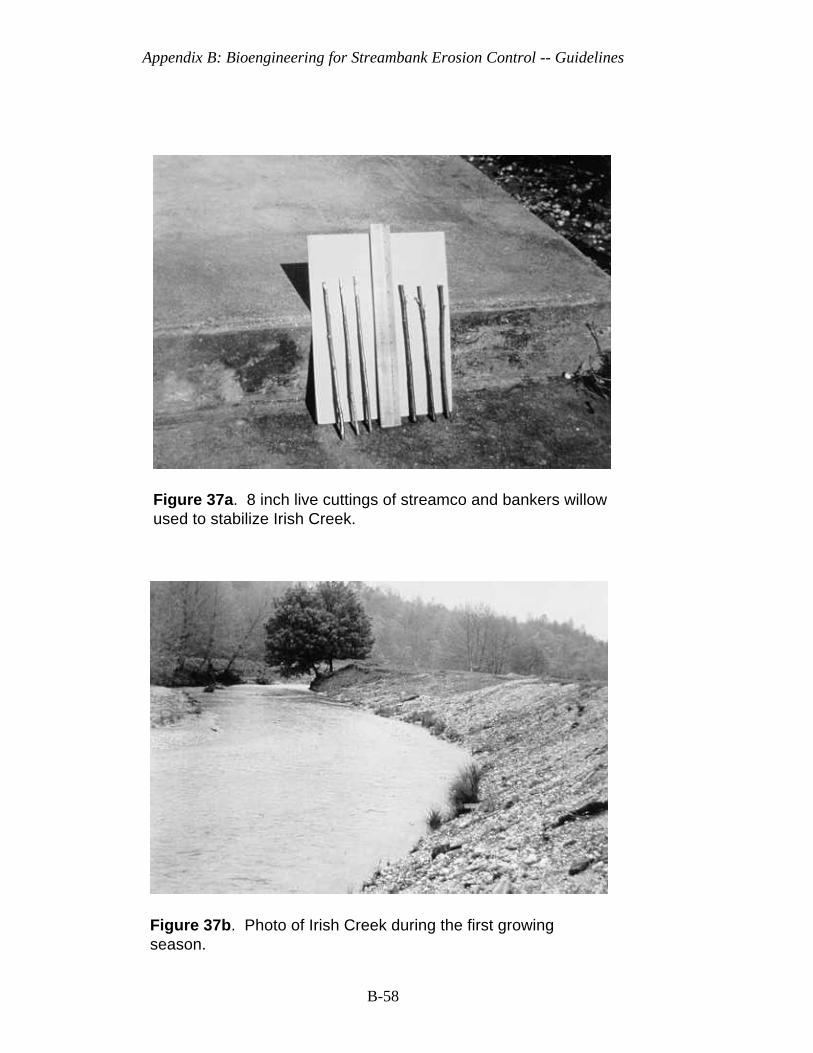
Appendix B: Bioengineering for Streambank Erosion Control -- Guidelines
B-58
Figure 37a. 8 inch live cuttings of streamco and bankers willowused to stabilize Irish Creek.
Figure 37b. Photo of Irish Creek during the first growingseason.
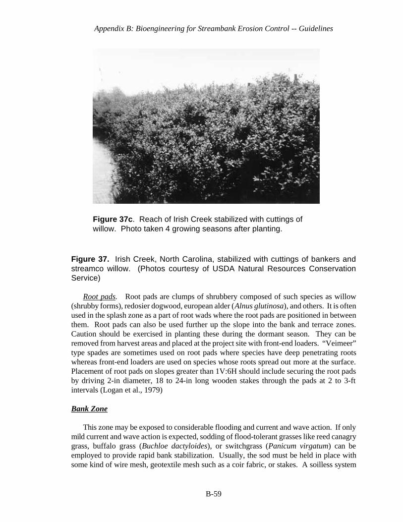
Appendix B: Bioengineering for Streambank Erosion Control -- Guidelines
B-59
Figure 37c. Reach of Irish Creek stabilized with cuttings ofwillow. Photo taken 4 growing seasons after planting.
Figure 37. Irish Creek, North Carolina, stabilized with cuttings of bankers andstreamco willow. (Photos courtesy of USDA Natural Resources ConservationService)
Root pads. Root pads are clumps of shrubbery composed of such species as willow(shrubby forms), redosier dogwood, european alder (Alnus glutinosa), and others. It is oftenused in the splash zone as a part of root wads where the root pads are positioned in betweenthem. Root pads can also be used further up the slope into the bank and terrace zones.Caution should be exercised in planting these during the dormant season. They can beremoved from harvest areas and placed at the project site with front-end loaders. “Veimeer”type spades are sometimes used on root pads where species have deep penetrating rootswhereas front-end loaders are used on species whose roots spread out more at the surface.Placement of root pads on slopes greater than 1V:6H should include securing the root padsby driving 2-in diameter, 18 to 24-in long wooden stakes through the pads at 2 to 3-ftintervals (Logan et al., 1979)
Bank Zone
This zone may be exposed to considerable flooding and current and wave action. If onlymild current and wave action is expected, sodding of flood-tolerant grasses like reed canagrygrass, buffalo grass (Buchloe dactyloides), or switchgrass (Panicum virgatum) can beemployed to provide rapid bank stabilization. Usually, the sod must be held in place withsome kind of wire mesh, geotextile mesh such as a coir fabric, or stakes. A soilless system
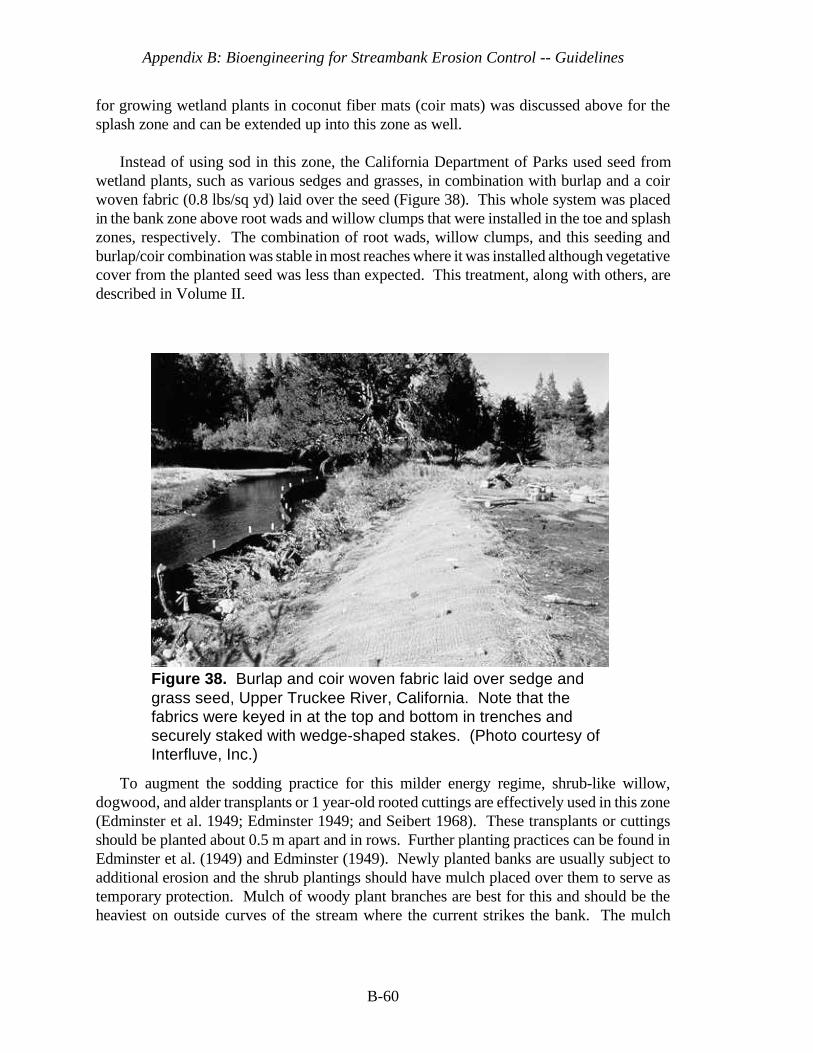
Appendix B: Bioengineering for Streambank Erosion Control -- Guidelines
B-60
Figure 38. Burlap and coir woven fabric laid over sedge andgrass seed, Upper Truckee River, California. Note that thefabrics were keyed in at the top and bottom in trenches andsecurely staked with wedge-shaped stakes. (Photo courtesy ofInterfluve, Inc.)
for growing wetland plants in coconut fiber mats (coir mats) was discussed above for thesplash zone and can be extended up into this zone as well.
Instead of using sod in this zone, the California Department of Parks used seed fromwetland plants, such as various sedges and grasses, in combination with burlap and a coirwoven fabric (0.8 lbs/sq yd) laid over the seed (Figure 38). This whole system was placedin the bank zone above root wads and willow clumps that were installed in the toe and splashzones, respectively. The combination of root wads, willow clumps, and this seeding andburlap/coir combination was stable in most reaches where it was installed although vegetativecover from the planted seed was less than expected. This treatment, along with others, aredescribed in Volume II.
To augment the sodding practice for this milder energy regime, shrub-like willow,dogwood, and alder transplants or 1 year-old rooted cuttings are effectively used in this zone(Edminster et al. 1949; Edminster 1949; and Seibert 1968). These transplants or cuttingsshould be planted about 0.5 m apart and in rows. Further planting practices can be found inEdminster et al. (1949) and Edminster (1949). Newly planted banks are usually subject toadditional erosion and the shrub plantings should have mulch placed over them to serve astemporary protection. Mulch of woody plant branches are best for this and should be theheaviest on outside curves of the stream where the current strikes the bank. The mulch
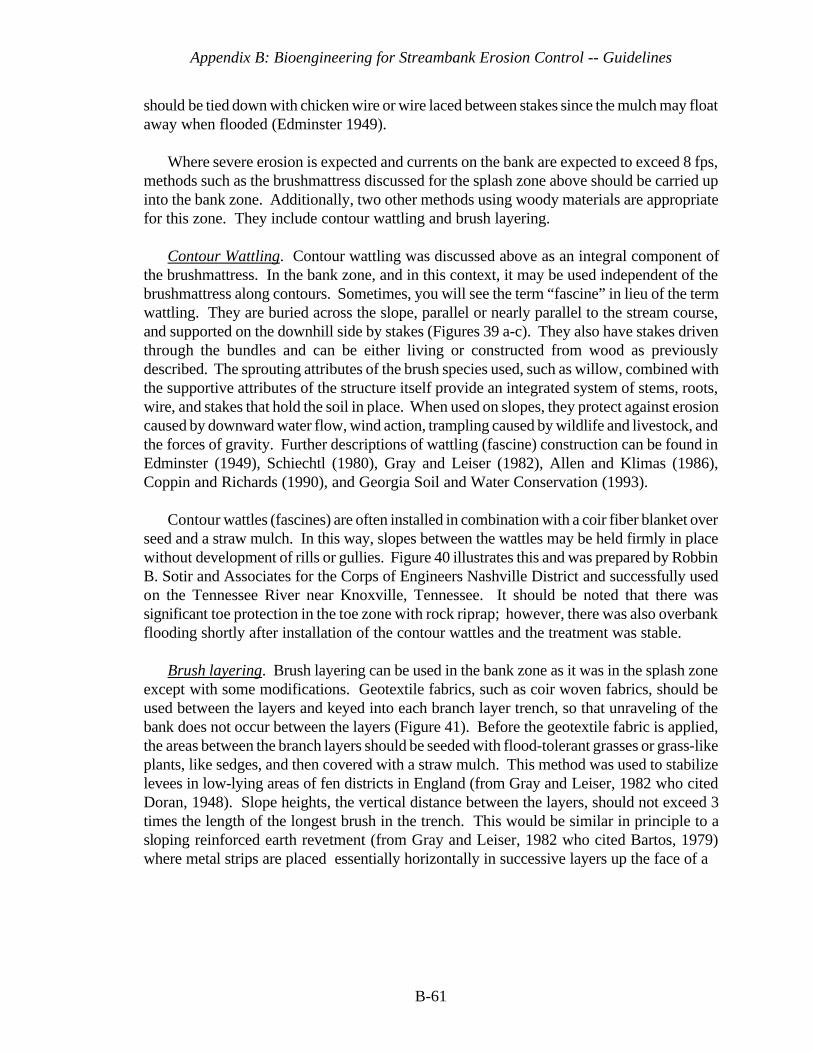
Appendix B: Bioengineering for Streambank Erosion Control -- Guidelines
B-61
should be tied down with chicken wire or wire laced between stakes since the mulch may floataway when flooded (Edminster 1949).
Where severe erosion is expected and currents on the bank are expected to exceed 8 fps,methods such as the brushmattress discussed for the splash zone above should be carried upinto the bank zone. Additionally, two other methods using woody materials are appropriatefor this zone. They include contour wattling and brush layering.
Contour Wattling. Contour wattling was discussed above as an integral component ofthe brushmattress. In the bank zone, and in this context, it may be used independent of thebrushmattress along contours. Sometimes, you will see the term “fascine” in lieu of the termwattling. They are buried across the slope, parallel or nearly parallel to the stream course,and supported on the downhill side by stakes (Figures 39 a-c). They also have stakes driventhrough the bundles and can be either living or constructed from wood as previouslydescribed. The sprouting attributes of the brush species used, such as willow, combined withthe supportive attributes of the structure itself provide an integrated system of stems, roots,wire, and stakes that hold the soil in place. When used on slopes, they protect against erosioncaused by downward water flow, wind action, trampling caused by wildlife and livestock, andthe forces of gravity. Further descriptions of wattling (fascine) construction can be found inEdminster (1949), Schiechtl (1980), Gray and Leiser (1982), Allen and Klimas (1986),Coppin and Richards (1990), and Georgia Soil and Water Conservation (1993).
Contour wattles (fascines) are often installed in combination with a coir fiber blanket overseed and a straw mulch. In this way, slopes between the wattles may be held firmly in placewithout development of rills or gullies. Figure 40 illustrates this and was prepared by RobbinB. Sotir and Associates for the Corps of Engineers Nashville District and successfully usedon the Tennessee River near Knoxville, Tennessee. It should be noted that there wassignificant toe protection in the toe zone with rock riprap; however, there was also overbankflooding shortly after installation of the contour wattles and the treatment was stable.
Brush layering. Brush layering can be used in the bank zone as it was in the splash zoneexcept with some modifications. Geotextile fabrics, such as coir woven fabrics, should beused between the layers and keyed into each branch layer trench, so that unraveling of thebank does not occur between the layers (Figure 41). Before the geotextile fabric is applied,the areas between the branch layers should be seeded with flood-tolerant grasses or grass-likeplants, like sedges, and then covered with a straw mulch. This method was used to stabilizelevees in low-lying areas of fen districts in England (from Gray and Leiser, 1982 who citedDoran, 1948). Slope heights, the vertical distance between the layers, should not exceed 3times the length of the longest brush in the trench. This would be similar in principle to asloping reinforced earth revetment (from Gray and Leiser, 1982 who cited Bartos, 1979)where metal strips are placed essentially horizontally in successive layers up the face of a
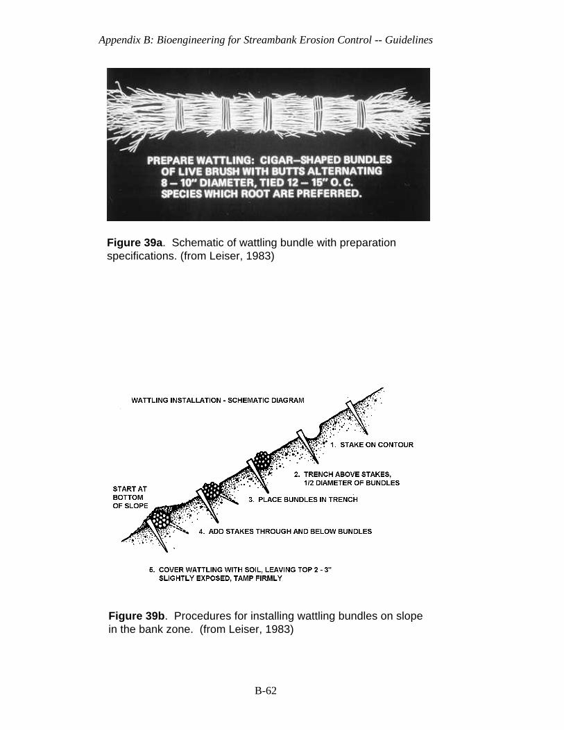
Appendix B: Bioengineering for Streambank Erosion Control -- Guidelines
B-62
Figure 39a. Schematic of wattling bundle with preparationspecifications. (from Leiser, 1983)
Figure 39b. Procedures for installing wattling bundles on slopein the bank zone. (from Leiser, 1983)

Appendix B: Bioengineering for Streambank Erosion Control -- Guidelines
B-63
Figure 39c. Wattling (fascine) bundle being installed in thebank zone. Note that wattling should not be covered completelywith soil; leave top 2-3" exposed for sprouting purposes. (Photo courtesy of Ms. Robin Sotir, Robin Sotir & Associates)
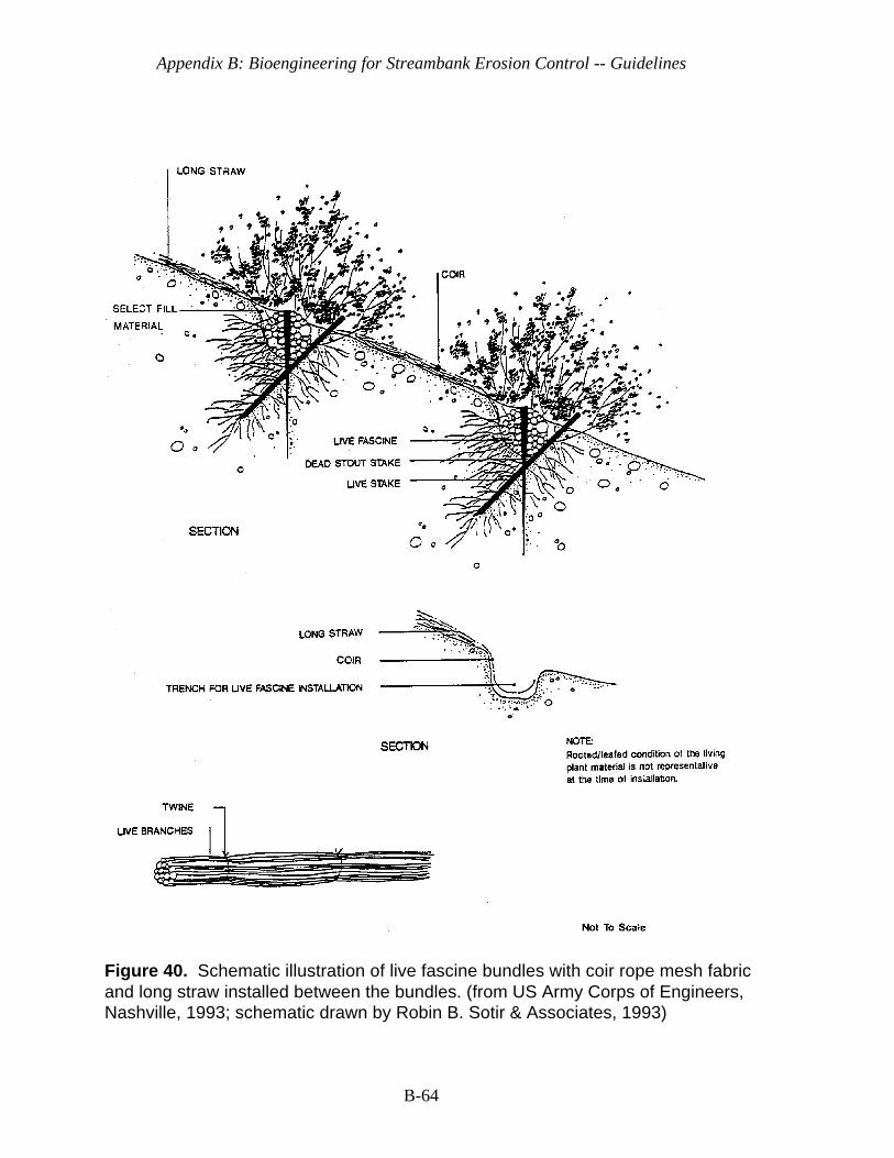
Appendix B: Bioengineering for Streambank Erosion Control -- Guidelines
B-64
Figure 40. Schematic illustration of live fascine bundles with coir rope mesh fabricand long straw installed between the bundles. (from US Army Corps of Engineers,Nashville, 1993; schematic drawn by Robin B. Sotir & Associates, 1993)

Appendix B: Bioengineering for Streambank Erosion Control -- Guidelines
B-65
Figure 41. Brush layering with coir woven fabric and long straw under fabric. Coir fabric and straw help control rillying and gullying between layers.(Adapted from Gray and Leiser, 1982)
slope. In a reinforced earth revetment it is common practice to make the strip length (orwidth of reinforced volume ) about one-third the slope height (Gray and Leiser, 1982).
Brush layering lends itself to partial mechanization because the benches can be excavatedwith a small backhoe or grader. Regular construction equipment, such as a front-end loaderwith a clasp on the bucket, can be used for hauling and placing the brush. Backhoes or similarequipment can also backfill.
The choice between wattling and brush layering, according to Gray and Leiser (1982),should be based on economics, the potential stability of the fill (in this case, stability of thestreambank), and the availability of suitable plant materials. Generally speaking, brushlayering is considered to be less expensive than contour wattling. Brush layering stabilizesa fill or bank to greater depths, but more plant material is required than for contour wattling.However, if the streambank is disturbed to the extent that rebuilding and reshaping isnecessary, brush layering may be the better alternative, because of its ability to stabilize a bankto greater depths.
Appendix B: Bioengineering for Streambank Erosion Control -- Guidelines
B-66
Again, as it was in the earlier parts of this report, emphasis should be placed on preventionof flanking of the bioengineering treatment. In this case, either contour wattling or brushlayering treatments should be protected with some kind of hard structure both upstream anddownstream of the treatment. If natural hard points, such as large boulders, rockoutcroppings, or hard geological strata, are not present, then one should consider use of arock refusal. This would be rock riprap that starts at the bottom of the bank, continues upthe bank, and is keyed into the bank (Figure 4).
Terrace Zone
This zone, as mentioned earlier, is rarely flooded and usually not subjected to erosiveaction of the stream except during occasional flooding. When flooded, it receives overbankflooding with return flows that can cause gullying and rilling to occur on the fall of thehydrograph. It is in this zone that vegetation is needed with deeply penetrating roots to holdthe bank together, such as larger flood-tolerant trees. Grasses, other herbs, and shrubs canbe planted in between the trees, depending on their shade tolerance. Bioengineering, per se,is not normally used in this zone unless there are deep gullies that have occurred as a resultof return flows or slopes still occur in this zone that are 3H:1V or greater. In these cases,branch layering or contour wattling treatments are often employed across the gully or on thecontours of the slope.
Care should be taken in using large trees in this zone. They should be planted far enoughback from the bank that their shade does not kill out the vegetation in the splash and bankzones. Narrow channels, especially, can be completely shaded from one side. When trees areplanted in this zone, they are planted either as container-grown (potted) or bare-root plants.Suggestions vary on the size of container-grown plants. Leiser (1994) suggests usingcontainers with a minimum size of 9 cubic inches with a depth of 8 inches and a maximum sizeof no larger than one quart milk carton. Plants in larger containers increase the cost forpurchase and planting substantially. Survival is frequently reduced because of limited rootsystems in relation to size of the tops of the plants (Leiser, 1994). The important thing toremember is to have a container with growing medium well filled with roots so that the rootsand medium form a cohesive unit when removed from the container.
Woody materials (Hoag 1994b), whether they be grown in containers or derived fromcuttings, should be used only in the bank and terrace zones when the following conditionsexist:
a. where long periods of inundation or water erosion are minimized;b. where adequate moisture is available, i.e., natural precipitation is adequate for
species selected or plants are irrigated;c. where there is no competing vegetation or a 30" diameter area around plant is
scalped of competing vegetation at planting time;d. where plants have a low risk of physically being pulled or eroded out due to shallow
rooting system during the first year after being planted.
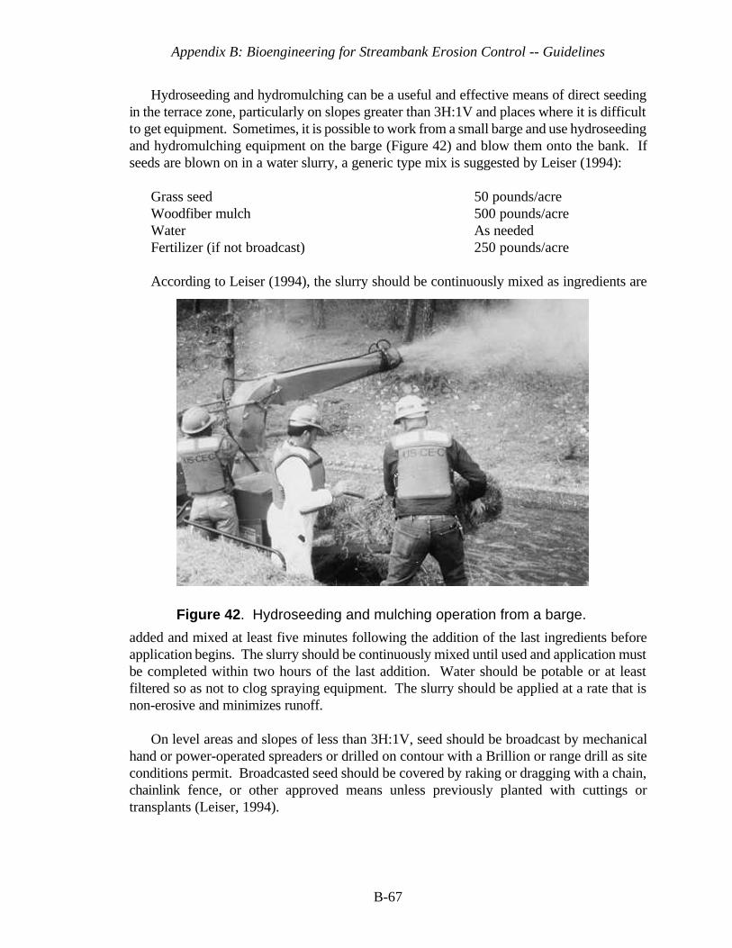
Appendix B: Bioengineering for Streambank Erosion Control -- Guidelines
B-67
Figure 42. Hydroseeding and mulching operation from a barge.
Hydroseeding and hydromulching can be a useful and effective means of direct seedingin the terrace zone, particularly on slopes greater than 3H:1V and places where it is difficultto get equipment. Sometimes, it is possible to work from a small barge and use hydroseedingand hydromulching equipment on the barge (Figure 42) and blow them onto the bank. Ifseeds are blown on in a water slurry, a generic type mix is suggested by Leiser (1994):
Grass seed 50 pounds/acreWoodfiber mulch 500 pounds/acreWater As neededFertilizer (if not broadcast) 250 pounds/acre
According to Leiser (1994), the slurry should be continuously mixed as ingredients are
added and mixed at least five minutes following the addition of the last ingredients beforeapplication begins. The slurry should be continuously mixed until used and application mustbe completed within two hours of the last addition. Water should be potable or at leastfiltered so as not to clog spraying equipment. The slurry should be applied at a rate that isnon-erosive and minimizes runoff.
On level areas and slopes of less than 3H:1V, seed should be broadcast by mechanicalhand or power-operated spreaders or drilled on contour with a Brillion or range drill as siteconditions permit. Broadcasted seed should be covered by raking or dragging with a chain,chainlink fence, or other approved means unless previously planted with cuttings ortransplants (Leiser, 1994).
Appendix B: Bioengineering for Streambank Erosion Control -- Guidelines
B-68
Sometimes surface drainage water intercepts the terrace zone from inland areas and cancause gullying not only in the terrace zone, but in the other zones on the bank. This watershould be diverted or controlled with a small furrow or trench at the top of the bank. Thistrench should be sodded to prevent erosion.
Velocities for Design Purposes
The purpose of this section is to provide some velocity information that bioengineeringsystems have been noted to sustain so that planners and designers have a basis for choosingbioengineering systems and the particular kind of system. Some of the velocity informationwas derived from the literature while other information was measured at local points at casestudy locations where bioengineering treatments were installed. Velocities vary so muchwithin a stream that local velocities near the treated section are the most valuable.Admittedly, the measured velocities are much lower than considered maximum thresholdvalues that could be sustained by the installed structures. This is because when measurementswere made, they were made with current meters in the local vicinity of the bioengineeringtreatment on the fall of the hydrograph when water levels and currents during flood eventswere not a safety hazard. Remote current meters exist, but would have been silted in ordamaged by debris flow during these flood events.
Most of the velocity information in the literature concerns itself with turf grass cover thatwas designed for erosion control ditches or waterways. Little information exists oncombinations of systems, i.e., bioengineering treatments, containing both herbaceous andwoody species. Engineer Manual, EM 1110-2-1205 (US Army Corps of Engineers, 1989),states that herbaceous or woody vegetation may be used to protect channel side slope areas(depending on the frequency of inundation, velocity, and geotechnical constraints toinfrequent flooding) and other bank areas where velocities are not expected to exceed 6 to8 feet per second (fps). Information concerning influence of vegetation (bermuda grass) orvariation of velocity with depth below water surface is shown in Henderson and Shields(1984) who cites Parsons (1963).
The splash and bank zones will be the principal focus for bioengineering applications. Itis in these zones that the designer must tailor vegetation types and bioengineering structuresto be commensurate with velocities that they can sustain. Hoag (1993) suggests thatmaximum flow velocities should not exceed 3 fps for herbaceous plantings, 3-5 fps for woodyand herbaceous mixed plantings, 5-8 fps for woody plantings alone, and that maximum flowsabove 8 fps require soil-bioengineering approaches.
For the case studies examined and monitored for this report, measured velocities for localflow conditions around the bioengineering treatment never exceeded 10 fps. Maximumvelocities sustained and recorded by bioengineering treatment types are shown in Table 2.As previously mentioned, these may not represent the maximum velocities encountered, asthey were usually taken on the fall of the hydrograph. Also, local roughness imparted by thebioengineering treatment would have slowed velocities in its vicinity.
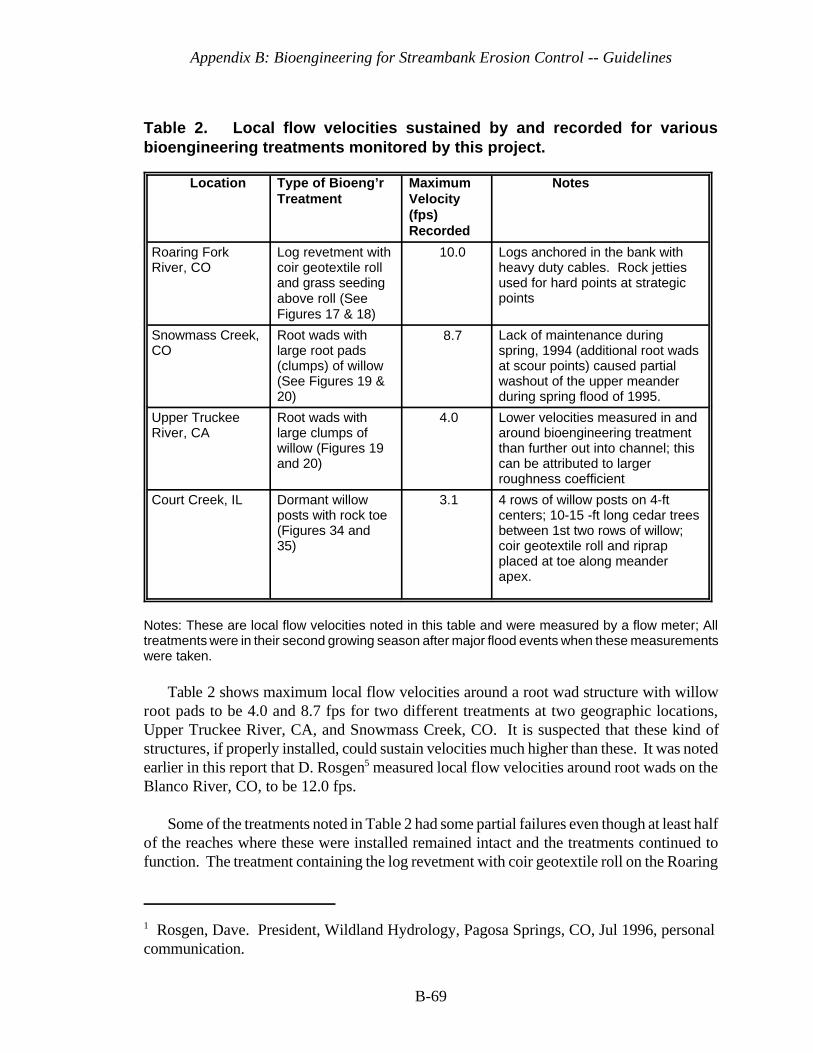
Appendix B: Bioengineering for Streambank Erosion Control -- Guidelines
1 Rosgen, Dave. President, Wildland Hydrology, Pagosa Springs, CO, Jul 1996, personalcommunication.
B-69
Table 2. Local flow velocities sustained by and recorded for variousbioengineering treatments monitored by this project.
Location Type of Bioeng’rTreatment
MaximumVelocity(fps)Recorded
Notes
Roaring ForkRiver, CO
Log revetment withcoir geotextile rolland grass seedingabove roll (SeeFigures 17 & 18)
10.0 Logs anchored in the bank withheavy duty cables. Rock jettiesused for hard points at strategicpoints
Snowmass Creek,CO
Root wads withlarge root pads(clumps) of willow(See Figures 19 &20)
8.7 Lack of maintenance duringspring, 1994 (additional root wadsat scour points) caused partialwashout of the upper meanderduring spring flood of 1995.
Upper TruckeeRiver, CA
Root wads withlarge clumps ofwillow (Figures 19and 20)
4.0 Lower velocities measured in andaround bioengineering treatmentthan further out into channel; thiscan be attributed to largerroughness coefficient
Court Creek, IL Dormant willowposts with rock toe(Figures 34 and35)
3.1 4 rows of willow posts on 4-ftcenters; 10-15 -ft long cedar treesbetween 1st two rows of willow;coir geotextile roll and riprapplaced at toe along meanderapex.
Notes: These are local flow velocities noted in this table and were measured by a flow meter; Alltreatments were in their second growing season after major flood events when these measurementswere taken.
Table 2 shows maximum local flow velocities around a root wad structure with willowroot pads to be 4.0 and 8.7 fps for two different treatments at two geographic locations,Upper Truckee River, CA, and Snowmass Creek, CO. It is suspected that these kind ofstructures, if properly installed, could sustain velocities much higher than these. It was notedearlier in this report that D. Rosgen5 measured local flow velocities around root wads on theBlanco River, CO, to be 12.0 fps.
Some of the treatments noted in Table 2 had some partial failures even though at least halfof the reaches where these were installed remained intact and the treatments continued tofunction. The treatment containing the log revetment with coir geotextile roll on the Roaring
Appendix B: Bioengineering for Streambank Erosion Control -- Guidelines
B-70
Fork River, CO, experienced some failure. The lower half of the reach in which it wasinstalled washed out after a major flood in the spring of 1995. This was due to the problemof insufficiently burying and keying in the bottom-most log of the revetment into thestreambed. Consequently, scour undermined the structure and it failed along the lower halfof the reach.
The root wad structure on Snowmass Creek, CO, had a partial failure. After the springrunoff in 1994, the sponsor noticed minor damage around certain critical points that neededmaintenance, the addition of more root wad logs. The contractor instead placed rock atinappropriate places. Consequently, the creek flooded during the spring runoff of 1995 andthe outside of the lower section of the upper meander washed out and eroded about six feetof bank. In these two cases, it points to the need for properly keying in structures for toe andend protection and to monitoring and possible maintenance early in the life of abioengineering project. This early monitoring and maintenance should be included in theconstruction contract at the outset.
Appendix B: Bioengineering for Streambank Erosion Control -- Guidelines
B-71
3 Plant Acquisition And Handling
Almost all of the plants used in bioengineering can be considered wetland plants, eitherobligative or facultative. Some of the exceptions would occur in the terrace zone that isinfrequently flooded; however, all must be somewhat flood-tolerant. Both herbaceous andwoody plants are used. Herbaceous plants may be emergent aquatic plants like rushes andsedges or grasses and other forbs that require non-aquatic, but moist conditions at least partof the year. The herbaceous plants are usually acquired as vegetative material such as sprigs,rhizomes, and tubers. Sometimes seed is acquired, but is used when the threat of flooding islow in the bank and terrace zones. Otherwise, they would wash out quite easily unless theyare seeded underneath or in a geotextile mat or fabric that is securely anchored.
Woody plants used for bioengineering purposes usually consist of stem cuttings, thosethat quickly sprout roots and stems from the parent stem. These are plants such as willow,some dogwood, and some alder. They can be supplemented by bare-root or containerizedstock, particularly in the bank or terrace zones where they are not subjected to frequentflooding. Gray and Sotir (1996) list several such plants that can be used in bioengineering andrelate their flood tolerances, along with some other characteristics.
There are three suitable methods to acquire plants for bioengineering treatments. Eachhas, according to Pierce (1994), noteworthy advantages, but critical disadvantages that makeplant acquisition and handling an important and complex process. The three methods are to:a) purchase plants, b) collect plants from the wild; and c) propagate and grow plants.
Regardless of the method chosen, it is necessary to conduct the following steps (Pierce,1994):
a. Determine the available hydrologic regime and soil types. General positioning ofthe plant type, e.g., emergent aquatic, shrubby willow, should be in accordance withthe plant zone (splash, bank, and terrace) defined in Part II.
b. Prepare a list of common wetland plant species in the region and more preferably,in the watershed containing the stream of concern, and match those to thehydrology and substrate of the target streambank reach to be addressed.
c. Select species that will match the energy of the environment and the hydraulicconveyance constraints that may be imposed by the situation. For instance, one
Appendix B: Bioengineering for Streambank Erosion Control -- Guidelines
B-72
must be careful to use low-lying and flexible vegetation that lays down with waterflows if hydraulic conveyance must be maximized. In such cases, use flood-tolerantgrasses or grass-like plants and shrubby woody species.
d. Select species that will not be dug out or severely grazed by animals, especiallymuskrat (Ondatia zibethieus), nutria (Myocastor coypes), beaver, Canada geese,and carp (Cyprinus carpio). Other animals may influence plant growth and survival.If plants chosen are unavoidably vulnerable to animal damage, then plant protectionmeasures must be used, such as fencing, wire or nylon cages around them, or useof repellents.
e. Determine additional special requirements and constraints of the site. For instance,some sites may be prone to sediment deposition or have a bank geometry that isalmost vertical. In such cases, it may be difficult to obtain success with emergentaquatic plants that may become covered with sediment and suffocate or which havetoo deep of water in which to grow unless the bank is reshaped. The formersituation may necessitate the use of willow that can be planted as cuttings or postsand be less susceptible to complete coverage by sediment.
f. Prepare a suite of species that would be suitable. This may be limited to thosecurrently available from commercial sources if there is no possibility to collect in thewild or have plants contract grown.
Pierce (1994) also gives a number of steps and advantages and disadvantages of the threemethods of acquiring plants and these have been adapted with some modifications below.Each project will have unique situations, but the following will serve as a guide.
Purchasing Plants
a. Acquire a list of wetland plant suppliers, such as “Directory of Plant Vendors,”(USDA Soil Conservation Service, 1992). Request vendors' catalogs and plantavailability lists.
b. Determine in what condition the plants from each supplier are delivered, potted,bare root, rhizomes and tubers, or seed. This is important because if the plants areto be used in the splash zone where they may be partially covered with water, seedof emergent aquatic plants will not germinate under water.
c. Match the plant list against species availability, and do not assume that all speciesadvertised will be available in needed quantities.
d. Order samples, if available, and verify plant condition and identification.
e. Negotiate a flexible delivery schedule allowing for unpredicted delays in planting.
Appendix B: Bioengineering for Streambank Erosion Control -- Guidelines
B-73
f. Some suppliers may grow plants on contract but it will be necessary to contact themseveral months to a year before the plants are needed.
Advantages of Purchasing Plants
a. Plants are readily available at the planting location in predicted quantities and at therequired time.
b. No special expertise is required to collect or grow the plants.
c. No wild source for the plants must be found and there are no harvesting permits toobtain from state or local governments.
d. Cost can be more readily predicted and controllable than harvesting from the wildor growing your own.
Disadvantages of Purchasing Plants
a. Plants may arrive in poor condition.
b. Selection of species is limited.
c. Plants may not be adapted to the local environment. Contract growing may solvethis problem.
d. Cost may be high and shipping cost needs to be considered.
e. Quantities may be limited.
f. It may be necessary to store large quantities of plants and consequently necessitateprocurement of adequate and appropriate storage facilities.
Collecting Plants from the Wild
Collecting plants from the wild may be very demanding because of “hard-to-reach” plantsthat are off main access routes. Wild plants must then be moved immediately to a nursery orhold-over site or to the project site. Logistical and plant handling problems need to becarefully assessed and solutions planned well ahead of time. Care should be taken if thismethod is selected because of the possibility of contaminating the harvested donor plants withunwanted weedy species that could become a problem at the project site. Samples should becollected ahead of time in order to determine what kind of problems will be encountered in
Appendix B: Bioengineering for Streambank Erosion Control -- Guidelines
B-74
collecting, transporting, and storing each species. Caution should be exercised in collectingplants from harvesting areas so that the plant community is not extirpated, left functional, andthe ecosystem not damaged. This can be done by not harvesting in one spot, but dispersingthe harvest areas. Care should be taken by harvesting only fairly common plants. Certainly,rare plants should be avoided.
Advantages of Collecting Plants from the Wild
a. Plants are likely to be ecotypically adapted to the local environment.
b. Plants can often be collected at a low cost.
c. Plants can be collected as needed and will not require extended storage.
d. Availability of species is very flexible and can be adjusted as the need arises.
e. No special expertise is required to grow the plants.
f. A very wide diversity of plants is available.
Disadvantages of Collecting Plants from the Wild
a. Weedy species may contaminate the source area and be inadvertantly transplanted.
b. A suitable area must be found, and more than one donor area may need to belocated.
c. Plants may not be in an appropriate condition for planting. For instance, they maybe highly stressed, diseased, or insect infested.
d. Species must be accurately identified or rare plants or weeds may be harvested bymistake.
e. Cost of collection and logistics may be very high.
f. Outdoor hazards such as snakes, adverse weather, noxious plants, e.g., poison ivyand stinging nettles, parasites, and other inhibiting items may interfere withcollection efforts.
g. It is often necessary to procure a permit for collecting from native plant sources andwetlands, in particular.
Appendix B: Bioengineering for Streambank Erosion Control -- Guidelines
B-75
Growing Plants
Plants to be grown for planting can be grown in a greenhouse or other enclosed facilityor in the case of emergent aquatics, outdoor ponds or troughs containing water. In eithercase, the plants must first be acquired from the wild or other growers, and propagated. Ifseeds are used for propagation, they must first be stratified (subjected to various treatmentssuch as soaking and temperature differences), but germination requirements for most wetlandplant seeds are unknown. If a greenhouse is to be used, a number of limitations andconstraints must be overcome, such as room for pots, adequate ventilation, and requirementsor problems associated with fertilizing, watering, and disease and pest control.
Plants can be grown in coir carpets (Figures 25 a-c), mats, or rolls, to facilitate earlyestablishment, ease of transport, and rapid development. Emergent aquatic plants, especially,may be hydroponically grown in the greenhouse or in outside troughs. Then, they can betransported to the planting site ready to grow with roots already established in the carpet,mat, or roll. The Waterways Experiment Station used a coir carpet for this purpose in 1983for growing and transporting ready-to-grow plants to a site in Mobile Bay for erosion controlof dredged material. This same concept can be used along streambanks and can be used toan advantage when one is in an area with short growing seasons or where rapid installationis mandatory.
Advantages of Growing Plants
a. All of the advantages of purchasing plants can be realized.
b. The variety of species available can be as diverse as for plants collected in the wildand plants can be planted in large quantities.
c. Plants can be available earlier in the season than purchased or collected plants.
d. Low cost is one of the primary reasons to grow stock for planting.
Disadvantages of Growing Plants
a. Space and facilities must be dedicated to growing plants.
b. Personnel with time and expertise to grow the plants may not be available.
c. There is an up-front investment in both fixed and variable overhead items in orderto establish a growing facility and it may not be justified unless there is a large andcontinuing need for planting stock.

Appendix B: Bioengineering for Streambank Erosion Control -- Guidelines
B-76
Handling of Plant Materials
Plants need to be handled carefully to ensure their survival between the phases ofacquisition (purchasing, growing, or harvesting from the wild) and transplanting because theywill undergo transportation and planting shock. Many problems associated with poor plantsurvival occur from the handling of the plants between the nursery or collection site and theproject planting site. Generally, the plant material needs to be kept cool, moist, and shaded(Hoag, 1994). They must be treated as living material; if the living attributes are lost, thenthe project is much more prone to fail even though dead plant materials in a bioengineeringtreatment can offer some erosion control through their physical attributes, e.g., acting as bankarmor, runoff retention through checkdam effects, current and wave deflectors. Plants aremost easily collected when dormant. When plants are dormant, there is substantially moreforgiveness in how they are handled.
Woody Plants. Woody plants, particularly cuttings, should be collected when dormant;their survival decreases a lot if they are harvested and planted in a non-dormant state. Withbareroot or unrooted cuttings, keep them cool, moist, and in the dark until they are ready tobe planted (Hoag, 1994b). They can be stored in a large cooler at 24-32 deg F until justbefore planting. Cuttings can be stored in this manner for several months (Platts et al. 1987).The cuttings can be kept in a cooler, root cellar, garage, shop floor, or any place that is dark,moist, and cool at all times (Hoag, 1994b). Often, cuttings are placed on burlap and coveredwith sawdust or peat moss and then covered with burlap after being moistened.
Hoag (1994b) advocates soaking of cuttings for a minimum of 24 hours, whether they arecoming out of storage or directly after harvesting in the late winter to early spring (Hoag etal. 1991a; Hoag et al. 1991b; Hoag 1992). Some research recommends soaking the cuttingsfor as much as 10-14 days (Briggs and Munda 1992; Fenchel et al. 1988). The main criteriais that the cuttings need to be removed from the water prior to root emergence from the bark.This normally takes 7 to 9 days (Peterson and Phipps 1976). Soaking is important becauseit initiates the root growth process within the inner layer of bark in willows and poplars(Hoag, 1994b).
When woody plants are moved from the nursery, holding, or harvesting area, to theproject site, they should continue to receive careful handling by keeping them moist and freefrom wind dessication. The latter can be achieved by ensuring they are covered with a light-colored (to reflect heat) and moist tarp. In the case of cuttings, they can be moved to theproject site by moving them in barrels with water in them or some similar method. Actualplanting of the plants shall follow the digging of holes as soon as possible, preferably nolonger than 2-3 minutes, so that the excavated soil does not dry out. Use only the moist,excavated soil for backfill of the planting hole. Backfill should be tamped firmly to eliminateall voids and to obtain close contact between the root systems and the native soils. Whenusing containerized or balled and burlap stock, excess soil should be smoother and firmedaround the plants leaving a slight depression to collect rainfall. Plants should be placed 1 to2 inches lower than they were grown in the nursery to provide a soil cover over the rootsystem (Leiser, 1994).

Appendix B: Bioengineering for Streambank Erosion Control -- Guidelines
B-77
Herbaceous Plants. Plant handling requirements of herbaceous plants are even morerigorous than woody plants as a general rule because they are usually obtained in the springwhen nurseries have them ready to ship or when they are readily identified in the wild forcollection. At those times, they are very susceptible to dessication mortality. Consequently,they must be kept in a moist, shaded condition, or even better, in water-filled containers fromthe time of collection from the wild or receipt from the nursery to the time of transplanting.If herbaceous plants are identified and tagged for collection in the spring or summer, they canbe collected when dormant in the late fall or winter. During those times, they can be handledmore freely, but should still be prevented from drying out. When transporting from thenursery, holding, or harvesting area to the project site, this should be in a covered vehicle.If the weather is very hot, cooling from ice or refrigeration may be necessary. Exposure tohigh winds should be avoided. Plants can be placed in a water-filled ditch and covered withsoil in a shaded area for storage of several days while awaiting planting. It is best not to storeplants longer than necessary, and delivery should be scheduled to match planting dates.
If herbaceous plants are to be grown, they will need to be grown from seed or fromcollected rhizomes, tubers, or rooted stems or rootstock from the wild. Most wetland plantseed needs to be stratified and will not germinate under water even after stratification. Anexperienced wetlands nursery person should be consulted before attempting to grow wetlandplants from seed. Often, a cold treatment under water is necessary for stratification (Pierce,1994). There are various other stratification methods of wetland plants, such as hot and coldtemperature treatments and treatments with various fertilizers. Rhizomes, tubers, and rootedstems and rootstock of wetland herbaceous plants can be grown out in wet troughs or ditchesand ponds containing fertilized sand and peat moss. Only enough water is necessary to keepthe rhizomes, tubers, etc. from drying out. Plants can be grown out in the greenhouse overcolder months, but will require hardening before transfer to the project site.
Hoag (1994b) stated that hardening off can be accomplished by removing the plants fromthe greenhouse and placing them in a cool, partially shaded area for 1-2 weeks. This isgenerally a lathe or slat house. Some are constructed with snow fencing which has woodenslats woven together with wire. According to Hoag (1994b), this type of structure allows asmall amount of direct sunlight and solar radiation through the slats to the plants, but notenough to burn them. A partially shaded spot near the planting site will also work. It isimportant to keep the plants well watered and misted during the hardening off period.

Appendix B: Bioengineering for Streambank Erosion Control -- Guidelines
B-78
Figure 43. Illustrations of different expenditure profiles andmaintenance (implied) of inert structures and bioengineeringtreatments. (from Coppin and Richards, 1990)
4 Monitoring and Aftercare
The Philosophy of Monitoring and Aftercare
Most agencies and private entities cannot afford extensive monitoring in an operationalsetting in contrast to very definitive monitoring in a research and development setting. Thisdiscussion focuses on the operational setting. Bioengineering projects continue to growstronger and stronger, once bed degradation is controlled, toe undercutting and scouring atupper and lower ends of reach have been arrested, and plants become established. Deeplypenetrating plant roots hold the soil together and upper stems deflect current and wave energyand slow local flow velocities. Then, sedimentation takes place and other pioneer plants startto invade and further contribute to stability. The key, however, is to ensure that this early-onestablishment of plants takes place and this requires early monitoring and possibleremediation. Thus, early maintenance may be called for if this establishment is jeopardized.In contrast, traditional projects such as riprapped revetment, may not require maintenanceearly in the project life, but may need major maintenance at a much higher cost a few yearslater. So, bioengineering may require early-on monitoring and remediation with the trade-offbeing no maintenance or little maintenance in later years. Figure 43 (from Coppin andRichards, 1990) illustrates this point.
Appendix B: Bioengineering for Streambank Erosion Control -- Guidelines
B-79
Bioengineering projects need to be observed early after project construction for signs ofplant survival and development, as well as for streambank integrity. At least qualitativemonitoring should be done to assure that detrimental phenomena do not jeopardize theproject. For instance, Court Creek, Illinois, one of the project case studies discussed inVolume II, had an infestation of spider mites. Within a month or so after planting, spidermites had damaged almost all of the leaves on the willow that were being used forstabilization. Without remedial spraying, project failure could have resulted. In another casestudy, North River, Massachusetts (Volume II), a drought occurred the first year afterplanting and killed much of the planted emergent aquatic vegetation. Remedial planting hadto be done the following year to compensate for drought mortality. Also, along withvegetative development, streambank integrity needs to be observed to ensure that unravelingof the bank is not occurring from such actions as undercutting of the toe or flanking at theupper or lower ends of the treated section. If this is occurring, then corrective measures needto be taken immediately, such as placing more rock or some other hard structure in thoseplaces. Projects should be monitored at least a couple of years after development at aminimum. Preferably, they should be monitored through 1-2 flood events where currents aredirected on the treated bank. One can then assess whether the site remains stable or unravels.In the latter case, remediation can occur. Site monitoring in bioengineering projects shouldbe written into the contract specifications so that early remediation does not become a partof operational and maintenance costs, which often have to be budgeted separately withinmany agencies.
Direct Documentation of Erosion Protection
Aerial Photographic Monitoring. Each bioengineering reach and associated treatment,e.g., rock toe with brush matting, vegetative geogrid, should be monitored for erosion directlyby use of aerial photogrammetric techniques. This will allow evaluation of changes occuringat the land-water interface providing the procedures discussed below are used.
Aerial photo coverage should be flown at least twice a year for the first 2-3 years orimmediately after a flood event. Suggested times are in the spring and in the fall. Low-waterperiods are preferable. Photo flights should be highly controlled; that is, the scale of repeatedflights must be the same. A suggested scale is 1:1,000. Also, three ground control points ofknown location and dimensions should be used per frame to provide accuratephotogrammetric measurements and these should be orthogonally corrected when processedto negate distortion. Recommended film type in priority order is: (1) color infrared and (2)color. To allow comparisons of repeated photo coverage, flights must be made during lowwater periods and when river water levels correspond to each other; that is, at or belowprevious photographic periods. Overlays can be made on the photos which will delineate thewater-interface boundary. Subsequent overlays can be compared showing any changes in thewater-interface boundary (see Figure 44). Photographic measurements can then be made onthe overlays to determine amount of surface area lost to erosion.

Appendix B: Bioengineering for Streambank Erosion Control -- Guidelines
B-80
Figure 44. Aerial monitoring of bioengineering treatment. (from Logan et al. 1979)
Ground Photographic Coverage. Monitoring, at a minimum, should be an array ofphotographs taken from the same photo point in the same directions so that later comparisonsof streambank development or degradation can occur very readily. Preferably, this will beused to supplement the aerial photo coverage and measurements mentioned above. Photosshould be taken at established photo points with photos taken periodically for a givenazimuth. These should be taken at the same time the aerial photos are taken, again at lowwater periods, if possible; however, others can be taken at intermittent times if deemednecessary.
Ocular Description. As a further effort to document erosion, a description of any erosiveprocesses must be made at the same time the ground photos are made. Processes that mustbe documented and particularly noted include such things as slumping from geotechnicalfailures, rilling, gullying, toe undercutting or launching, flanking at upper or lower ends oftreatment, and scouring at other areas within the reach from either current or wave action.Descriptive estimates of degree of severity for each of the above processes per treatment andreach with backup photos should be made.

Appendix B: Bioengineering for Streambank Erosion Control -- Guidelines
B-81
Indirect Documentation of Erosion Protection
Erosion protection is assumed to be offered by the vegetation if the plants are survivingand developing; that is covering the site. The development of the vegetation needs to bemonitored and possibly correlated, at least from a visual standpoint to the degree of erosionor lack of erosion taking place on the treated streambank. One would assume, for example,that vegetative plantings are doing a good job if the vegetation is growing well in all elevationzones in the project area and if the stream is not undercutting the treatments, flanking them,or scouring them to the point of failure.
Aftercare
As mentioned above, early monitoring may mean some early remediation and maintenancejust to ensure long-term viability. What does this early remediation and maintenance mean?Does this constitute periodic irrigation or repeated fertilizer application? Not as a regularrule. However, plants should be well watered immediately after planting. Bioengineeringprojects are normally installed at a time of the year, such as early spring, where precipitationis sufficient to allow the planted vegetation to sprout roots and stems and obtain a footholdin their environment. Or, they are installed in the late fall during dormancy. Repeatedirrigation is not needed then. Hopefully, fertilizer and other soil treatments were appliedbefore or during planting, if needed, and they should not be required again, unless unusualcircumstances prevail.
Possible aftercare requirements may mean bolstering a particular treatment with additionalplant or even inert materials after an immediate flood event. Flooding may have caused someplants to wash out before they had a chance to secure themselves with their roots. Hopefully,engineered materials, such as wire, stakes, geotextile coverings, rock toes, etc. would havehelped hold the plants and soil until the plants become established, but sometimes any one ofthese materials, either plants or inert materials, may need bolstering.
Other aftercare measures, as mentioned above, may mean treating plants with aninsecticide or fungicide if insects or disease is widely prevalent. Usually, this will be theexception rather than the rule. One can overcome widespread insect or disease damage byemphasizing a wide diversity of plants in the plant mix so that if one species is attacked, thewhole vegetative treatment will not be jeopardized. Beaver and herbivores, such as geese,may be a problem in some cases by feeding on woody and emergent aquatic plants,respectively. Beaver will often chew off the upper part of willow and poplar cuttings, butthese can resprout and still perform satisfactorily if the complete cutting or stem is notchewed off or dislodged. In some cases, where beaver are known to be in the area, then atrapping program may be advised. Waterfowl, such as geese, like to grub out emergentaquatic plants as well as feed on the upper parts. Temporary fence corridors made out ofwooden slats with tiered twine attached to the slats have been shown to prevent geese fromfeeding on emergent aquatic plants. They do not like to feel trapped inside narrow confineswhere they cannot escape quickly.
Appendix B: Bioengineering for Streambank Erosion Control -- Guidelines
B-82
5 Costs of Bioengineering
Bioengineering treatments are normally much less expensive than traditional methods ofstreambank erosion control, e.g., riprapped revetment, bulkheads, but not always dependingon the environmental setting and the project objectives. Costs can vary tremendously byavailability of materials, hauling distances, prevailing labor rates for the geographic area, anda host of other factors. Table 3 illustrates cost comparisons of actual costs for a couple ofbioengineering installations compared to estimated costs of riprapped revetment for the samelocality under similar conditions. You will note that the first method, the dormant postmethod, installed in northwestern Illinois, was about one-fourth the cost of riprappedrevetment. The vegetative geogrid installed in California was about 4 times the cost ofriprapped revetment. In the first case, riprap was in short supply and cost much more which,in part, contributed to a higher cost than in the California example. Also, the dormant postmethod required cheaper materials and less labor than the vegetative geogrid in California.Riprap in the California example was fairly cheap and the slope distance to cover the bankwas not great, contributing to a cheaper installation than the vegetative geogrid. Also, thevegetative geogrid was fairly labor intensive. Labor accounted for 66 percent of the overallcosts. However, what is not shown in the California example is that the site is next to avaluable golf course and the sponsor is also trying to provide shaded riverine aquatic (SRA)habitat for native brown trout. The vegetative geogrid can be installed on nearly a verticalslope without much sacrifice to the adjacent land and it will provide the SRA habitat byproviding willow that overhang the banks. The riprapped revetment option does not provideoverhanging vegetation for good SRA habitat and does require more land to accommodateshaving the bank to an acceptable construction standard for riprap. It would have requiredeliminating some of the valuable golf course land. Thus, one must consider the projectobjectives and potential benefits and impacts when considering comparison of bioengineeringmethods with other traditional techniques.
When comparing bioengineering methods with traditional engineering applications,Coppin and Richards (1990) stated that each must be considered on its merits, comparing life-cycle costs, i.e. the net present value of investigation, design and construction, plus futuremanagement and replacement. As mentioned earlier, bioengineering will require a higherinvestment early in the project life to ensure that the living system is established. Then,maintenance drops off and the vegetation in the bioengineering treatment continues to grow,spread, and strengthen the streambank through its various attributes mentioned early
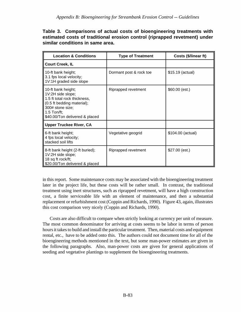
Appendix B: Bioengineering for Streambank Erosion Control -- Guidelines
B-83
Table 3. Comparisons of actual costs of bioengineering treatments withestimated costs of traditional erosion control (riprapped revetment) undersimilar conditions in same area.
Location & Conditions Type of Treatment Costs ($/linear ft)
Court Creek, IL
10-ft bank height;3.1 fps local velocity;1V:1H graded side slope
Dormant post & rock toe $15.19 (actual)
10-ft bank height;1V:2H side slope;1.5 ft total rock thickness,(0.5 ft bedding material);300# stone size;1.5 Ton/ft;$40.00/Ton delivered & placed
Riprapped revetment $60.00 (est.)
Upper Truckee River, CA
6-ft bank height;4 fps local velocity;stacked soil lifts
Vegetative geogrid $104.00 (actual)
8-ft bank height (2-ft buried);1V:2H side slope;18 sq ft rock/ft;$20.00/Ton delivered & placed
Riprapped revetment $27.00 (est.)
in this report. Some maintenance costs may be associated with the bioengineering treatmentlater in the project life, but these costs will be rather small. In contrast, the traditionaltreatment using inert structures, such as riprapped revetment, will have a high constructioncost, a finite serviceable life with an element of maintenance, and then a substantialreplacement or refurbishment cost (Coppin and Richards, 1990). Figure 43, again, illustratesthis cost comparison very nicely (Coppin and Richards, 1990).
Costs are also difficult to compare when strictly looking at currency per unit of measure.The most common denominator for arriving at costs seems to be labor in terms of personhours it takes to build and install the particular treatment. Then, material costs and equipmentrental, etc., have to be added onto this. The authors could not document time for all of thebioengineering methods mentioned in the text, but some man-power estimates are given inthe following paragraphs. Also, man-power costs are given for general applications ofseeding and vegetative plantings to supplement the bioengineering treatments.
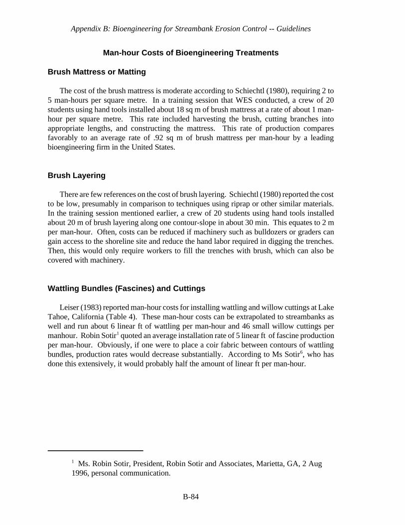
Appendix B: Bioengineering for Streambank Erosion Control -- Guidelines
1 Ms. Robin Sotir, President, Robin Sotir and Associates, Marietta, GA, 2 Aug1996, personal communication.
B-84
Man-hour Costs of Bioengineering Treatments
Brush Mattress or Matting
The cost of the brush mattress is moderate according to Schiechtl (1980), requiring 2 to5 man-hours per square metre. In a training session that WES conducted, a crew of 20students using hand tools installed about 18 sq m of brush mattress at a rate of about 1 man-hour per square metre. This rate included harvesting the brush, cutting branches intoappropriate lengths, and constructing the mattress. This rate of production comparesfavorably to an average rate of .92 sq m of brush mattress per man-hour by a leadingbioengineering firm in the United States.
Brush Layering
There are few references on the cost of brush layering. Schiechtl (1980) reported the costto be low, presumably in comparison to techniques using riprap or other similar materials.In the training session mentioned earlier, a crew of 20 students using hand tools installedabout 20 m of brush layering along one contour-slope in about 30 min. This equates to 2 mper man-hour. Often, costs can be reduced if machinery such as bulldozers or graders cangain access to the shoreline site and reduce the hand labor required in digging the trenches.Then, this would only require workers to fill the trenches with brush, which can also becovered with machinery.
Wattling Bundles (Fascines) and Cuttings
Leiser (1983) reported man-hour costs for installing wattling and willow cuttings at LakeTahoe, California (Table 4). These man-hour costs can be extrapolated to streambanks aswell and run about 6 linear ft of wattling per man-hour and 46 small willow cuttings permanhour. Robin Sotir1 quoted an average installation rate of 5 linear ft of fascine productionper man-hour. Obviously, if one were to place a coir fabric between contours of wattlingbundles, production rates would decrease substantially. According to Ms Sotir6, who hasdone this extensively, it would probably half the amount of linear ft per man-hour.

Appendix B: Bioengineering for Streambank Erosion Control -- Guidelines
B-85
Table 4. Man-hour costs of installing wattling and willow cuttings at LakeTahoe in 1973. (Leiser 1983)
Prepare and install wattling (1,140 linear ft)
Labor Man-hours
C Scaling or cutting back the bank or slope 2
C Cutting willow whips 27
C Prepare (stack, tie, load) 28
C Layout 9
C Install 75
C Downtime (rain) 10
C Travel (from Sacramento, Marysville) 42
193
Unit Man-hour Cost: 1,140/193 = 5.9 linear ft per man-hour
Prepare and plant willow cuttings (8,000 cuttings)
Labor Man-hours
C Scaling 2
C Cutting 9
C Prepare 34
C Plant 76
C Downtime (rain) 10
C Travel (from Sacramento, Marysville) 42
173
Unit Man-hour Cost: 8,000/173 = 46.2 cuttings per man-hour
Dormant Willow Post Method
Roseboom (1995) reported that for bioengineering work on a 600-ft reach at CourtCreek, Illinois, it took 5 men two 8-hr days to install 675 willow (12- ft tall) posts on 4-ftcenters. This also included installation of a rock toe (20 tons of 10" riprap) with a coirgeotextile roll along 300 ft. Also, 60 cedar trees were laid and cabled along the the toe of theslope to trap sediment. This included an excavator operator along with the 4 other menpreviously mentioned. This equates to about 17 posts per man-hour that includes harvesting
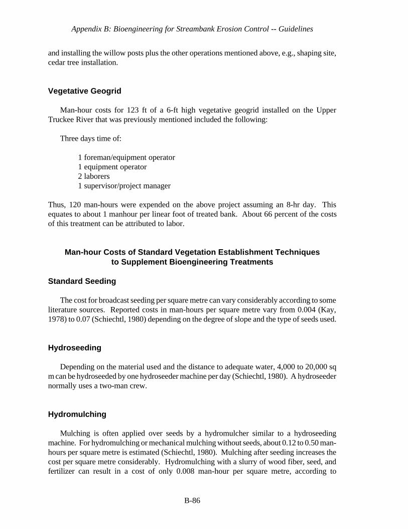
Appendix B: Bioengineering for Streambank Erosion Control -- Guidelines
B-86
and installing the willow posts plus the other operations mentioned above, e.g., shaping site,cedar tree installation.
Vegetative Geogrid
Man-hour costs for 123 ft of a 6-ft high vegetative geogrid installed on the UpperTruckee River that was previously mentioned included the following:
Three days time of:
1 foreman/equipment operator1 equipment operator2 laborers1 supervisor/project manager
Thus, 120 man-hours were expended on the above project assuming an 8-hr day. Thisequates to about 1 manhour per linear foot of treated bank. About 66 percent of the costsof this treatment can be attributed to labor.
Man-hour Costs of Standard Vegetation Establishment Techniquesto Supplement Bioengineering Treatments
Standard Seeding
The cost for broadcast seeding per square metre can vary considerably according to someliterature sources. Reported costs in man-hours per square metre vary from 0.004 (Kay,1978) to 0.07 (Schiechtl, 1980) depending on the degree of slope and the type of seeds used.
Hydroseeding
Depending on the material used and the distance to adequate water, 4,000 to 20,000 sqm can be hydroseeded by one hydroseeder machine per day (Schiechtl, 1980). A hydroseedernormally uses a two-man crew.
Hydromulching
Mulching is often applied over seeds by a hydromulcher similar to a hydroseedingmachine. For hydromulching or mechanical mulching without seeds, about 0.12 to 0.50 man-hours per square metre is estimated (Schiechtl, 1980). Mulching after seeding increases thecost per square metre considerably. Hydromulching with a slurry of wood fiber, seed, andfertilizer can result in a cost of only 0.008 man-hour per square metre, according to

Appendix B: Bioengineering for Streambank Erosion Control -- Guidelines
B-87
calculations derived from Kay (1978), who reviewed contractor costs in California. Theabove man-hour calculations assume the following: use of a four-man mulching machine,seed and fertilizer applied at a rate of 0.75 ton per acre, and an application rate of 2 tons perhour.
Sprigs, Rootstocks or Plugs, Rhizomes, and Tubers
Costs for digging grasses and other herbaceous plants in their native habitat and transplanting propagules of these will vary depending on the harvesting system used, theplacement of the plants, and the site. For digging, storing and handling, and planting 1,000plants of sprigged wetland grasses and sedges, Knutson and Inskeep (1982) reported a rateof about 10 man-hours. Sprigs of this type were placed on 0.5-m centers, which would cover250 sq m. For the same kinds of plants, Allen, Webb, and Shirley (1984) reported a rateequivalent to 400 plants per 10 man-hours for digging, handling, and planting single sprigs.According to Knutson and Inskeep (1982), using plugs of any species (grass or forb) is atleast three times more time-consuming than using sprigs (30 man-hours per 1,000 plugs).
Bare-root Tree or Shrub Seedlings
Depending on type of plant and local conditions, the reported costs of planting varyconsiderably. On good sites with deep soils and gentle slopes, the authors have experiencedplanting up to between 100 and 125 plants per man-hour. Logan et al. (1979), however,estimated that only 200 to 400 plants per day per person could be achieved on sites like thebanks of the upper Missouri River.
Ball and Burlap Trees or Shrubs
Planting costs for this type of transplant will range from 10 to 25 plants per man-hour(Schiechtl, 1980).
Containerized Plantings
The cost of plantings varies depending on plant species, pot type, and site conditions. Byusing pots other than paper, 20 to 40 plants per man-hour can be planted. With paper pots,up to 100 plants per man-hour can be planted (Schiechtl, 1980). Logan et al. (1979) statedthat the cost for hand-planting containerized stock ranges from one-half the cost for bare-rootseedlings to a cost equal to or exceeding that of the container seedling.

Appendix B: Bioengineering for Streambank Erosion Control -- Guidelines
B-88
6 SUMMARY AND RECOMMENDATIONS
Bioengineering can be a useful tool in controlling bank erosion, but should not beconsidered a panacea. It needs to be performed in a prudent manner and in consonance withgood planform and channel bed stability design. It must be done with the landscape andwatershed in mind, particularly with respect to erosion that has occurred as a result of bothbroad basinwide activities and local, site-specific causes. Nevertheless, bioengineering mustbe done at the reach level. This must be done in a systematic way with thought given to itseffects both upstream and downstream and it may have to be done incrementally to overcomeseasonal time constraints. For instance, woody plants must be planted in the dormant season.There are numerous questions that must be answered prior to bioengineering implementation.Answering these questions and designing a project must be an integrated process that startswith the planning phase and continues through the construction phase. There are obviouslyfeedback loops from the design and construction phases back to the planning phase.Additional information may have to be retrieved that calls for more planning actions.
Bioengineering must be accomplished with enough hardness to prevent both undercuttingof the streambank toe and erosion of the upper and lower ends (flanking) of the treated reach.This can be done with one or both of: (1) hard toe and flanking protection, e.g., rock riprap,refusals, and (2) deflection of water away from the target reach to be protected throughdeflection structures, e.g., groins, hard points, vanes, and dikes. With both of these methods,only appropriate plant species should be used in a manner consistent with their naturalhabitats. This is often done by using streambank zones that correspond with micro-habitatsof native plant species in local stream environments. Where possible, both herbaceous andwoody species are used with grass or grass-like plants, e.g., sedges, rushes, reed grasses, inthe lower-most zone, then shrubby, woody vegetation in the middle zone, and for the mostpart, larger shrubs and trees in the upper-most zone. These zones are respectively called the“splash, bank, and terrace zones.”
Careful planning must be done to acquire the kinds of plants in the amounts needed. Thismay take up to one year before installation of the various treatments because plants eitherhave to be grown in sufficient quantities in nurseries or they have to be located in the wild andeither collected or grown from wild plant stock.
Bioengineering treatments have been noted, depending on the type of treatment, to resistup to 12 fps local flow velocities. It is recognized, however, that local flow velocities duringpeak discharges are difficult to obtain during those events because of safety considerations.
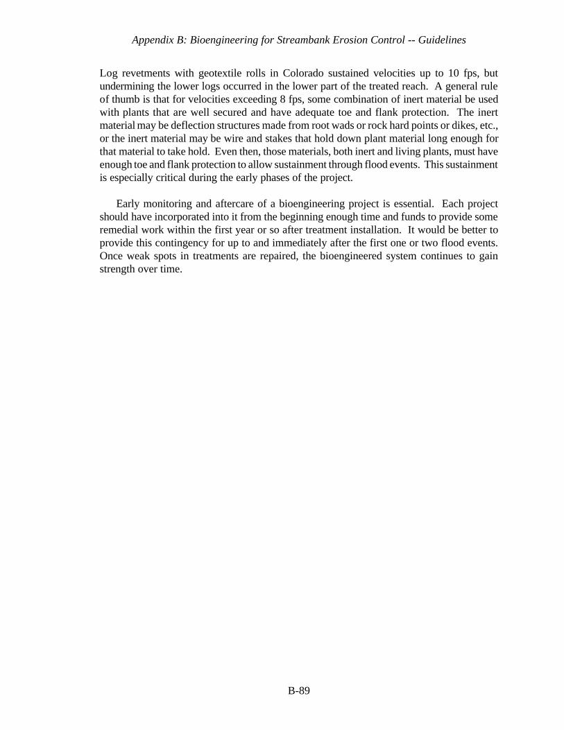
Appendix B: Bioengineering for Streambank Erosion Control -- Guidelines
B-89
Log revetments with geotextile rolls in Colorado sustained velocities up to 10 fps, butundermining the lower logs occurred in the lower part of the treated reach. A general ruleof thumb is that for velocities exceeding 8 fps, some combination of inert material be usedwith plants that are well secured and have adequate toe and flank protection. The inertmaterial may be deflection structures made from root wads or rock hard points or dikes, etc.,or the inert material may be wire and stakes that hold down plant material long enough forthat material to take hold. Even then, those materials, both inert and living plants, must haveenough toe and flank protection to allow sustainment through flood events. This sustainmentis especially critical during the early phases of the project.
Early monitoring and aftercare of a bioengineering project is essential. Each projectshould have incorporated into it from the beginning enough time and funds to provide someremedial work within the first year or so after treatment installation. It would be better toprovide this contingency for up to and immediately after the first one or two flood events.Once weak spots in treatments are repaired, the bioengineered system continues to gainstrength over time.
Appendix B: Bioengineering for Streambank Erosion Control -- Guidelines
B-90
References
Allen, H. H., Pierce, G. J., and Van Wormer, R. (1989). “Considerations and techniques for
vegetation establishment in constructed wetlands,” In: Constructed Wetlands forWastewater Treatment, Hammer, D. A. (ed.), Lewis Publishers, Chelsea, MI, pp. 405-415.References
Allen, H. H. and Klimas, C. V. (1986). “Reservoir shoreline revegetation guidelines,”Technical Report E-86-13, U.S. Army Engineer Waterways Experiment Station,Vicksburg, MS.
Allen, H. H. (1978). “Role of wetland plants in erosion control of riparian shorelines,”Proceedings of the National Symposium on Wetlands, American Water ResourcesAssociation, Minneapolis, Minnesota, pp. 403-414.
Bailey, R. W., and Copeland, O. L. (1961). “Vegetation and engineering structures in floodand erosion control,” U. S. Department of Agriculture Intermountain Forest and RangeExperiment Station, Ogden, Utah. Paper presented at 13th Congress of InternationalUnion of Forest Research Organizations, Vienna, Austria. September 10-17, 1961.
Bartos, M. J. (1979). “101 uses for earth reinforcement,” Civil Engr. 49(1):51-57. Bowers, K. (1992). “Little Patuxent River - Stream Restoration,” Land and Water,
July/August.
Briggs, J. A. and Munda, B. (1992). “Collection, evaluation, selection, and production ofcottonwood poles for riparian area improvement,” Final Report to the US Fish & WildlifeService. USDA-SCS, Tucson Plant Materials Center, Tucson, AZ. 32 pp.
Coppin, N. J. and Richards, I. G. (1990). Use of Vegetation in Civil Engineering.Butterworths, London.
Derrick, D. (1996). “The bendway weir: an in-stream erosion control and habitatimprovement structure for the 1990's,” In: Proceedings of Conference XXVII, February27 - March 1, 1996, Seattle, Washington, International Erosion Control Association, pp.229-241.
Appendix B: Bioengineering for Streambank Erosion Control -- Guidelines
B-91
Doran, W. E. (1948). “Stabilization of river banks,” In: Proc., 2nd Intl. Conf. on Soil Mech.and Foundation Eng., London, Vol. 2, pp. 60-63.
Edminster, F. C., Atkinson, W. S., and McIntyre, A. C. (1949). “Streambank erosion controlon the Winooski River, Vermont,” U.S. Department of Agriculture Circular No. 837,U.S. Government Printing Office, Washington, D.C.
Edminster, F. C. (1949). “Streambank plantings of erosion control in the Northeast,” U.S.Department of Agriculture Leaflet No. 258, U.S. Government Printing Office,Washington, D.C.
Fenchel, G., Oaks, W., and Swenson, E. (1988). “Selecting desirable woody vegetation forenvironmental mitigation and controlling wind erosion and undesirable plants in the RioGrande and Pecos River Valleys of New Mexico,” Five year interim report (1983-87).Los Lunas, NM: USDA-SCS Los Lunas Plant Materials Center. 49 pp.
Georgia Soil and Water Conservation (1994). “Guidelines for Streambank Restoration,”Athens, Georgia.
Goldsmith, W. (1993). “First year monitoring report, North River streambank stabilizationbioengineering demonstration project, Colrain, Massachusetts,” Unpublished ContractReport (#DACW39-93-M-5454) for U.S. Army Engineer Waterways Experiment Station,Vicksburg, MS.
Gray, D. H. and Leiser, A. T. (1982). Biotechnical slope protection and erosion control,Van Nostrand Reinhold Co., New York, 271 pp.
Gray, D. H. and Sotir, R. B. (1996). Biotechnical and soil bioengineering slopestabilization: a practical guide for erosion control, John Wiley & Sons, Inc., New York,313 pp.
Gray, D. H. 1977. “The influence of vegetation on slope processes in the Great LakesRegion,” Proceedings: Workshop on the Role of Vegetation in Stabilization of theGreat Lakes Shoreline, Great Lakes Basin Commission, Ann Arbor, Michigan, pp. 5-29.
Henderson, J. E. and Shields, F. D., Jr. (1984). “Environmental features for streambankprotection projects,” Technical Report E-84-11, US Army Engineer WaterwaysExperiment Station, Vicksburg, MS, 119 pp.
Hoag, C. (1993). “How to plant willows and cottonwoods for riparian rehabilitation,” TNPlant Materials No. 23, September, 1993, USDA Soil Conservation Service, Boise, ID.
Hoag, C. (1994a). “The Stinger,” TN Plant Materials No. 6, June 1994, USDA SoilConservation Service, Boise, ID.
Appendix B: Bioengineering for Streambank Erosion Control -- Guidelines
B-92
Hoag, C. (1994b). “Use of willow poles and spikes at American Falls Reservoir, Idaho,”Notes from “Reservoir Shoreline Erosion/Revegetation Workshop,” Lewisville and RayRoberts Lakes, Denton, TX, 28 March - 1 April, 1994, U.S. Army Engineer WaterwaysExperiment Station, Vicksburg, MS.
Hoag, J. C. (1992). “Planting techniques from the Aberdeen, ID, Plant Materials Center forvegetating shorelines and riparian areas,” In: Proceedings--Symposium on Ecology andManagement of Riparian Shrub Communities. USDA Forest Service Gen. Tech. Rep.RM-65, Rocky Mountain Forest and Range Experiment Station, Ft. Collins, CO. pp 163-166.
Hunter, C. J. (1991). (ed. by Palmer, T.). Better Trout Habitat, A Guide to StreamRestoration and Management, Island Press, Wash. D. C. 320 pp.
Kay, B. L. (1978). “Mulches for erosion control and plant establishment on disturbed sites,”In: Proceedings--ALCA's 1978 Revegetation Erosion Control Symposium, August 1-3,1978, Denver, CO, pp 111-129.
Klingeman, P. C., and Bradley, J. B. (1976). “Willametted River Basin streambankstabilization by natural means,” U.S. Army Corps of Engineers, Portland District,Portland, Oregon.
Knutson, P. L., and Inskeep, M. R. (1982). “Shore erosion control with salt marshvegetation,” Coastal Engineering Technical Aid No. 82-3, US Army Engineer CoastalEngineering Research Center, Vicksburg, MS.
Knutson, P. L., Allen, H. H., and Webb, J. W. (1990). “Guidelines for vegetative erosioncontrol on wave-impacted coastal dredged material sites,” Technical Report D-90-13,U.S. Army Engineer Waterways Experiment Station, Vicksburg, MS.
Leiser, A. T. (1983). “Reservoir Shoreline Revegetation,” paper presented at US ArmyCorps of Engineers training course, Wetlands Development and Restoration, Duck, NC.
Leiser, A. T. (1994). “Biotechnical approaches for shoreline erosion control,” Notes from“Reservoir Shoreline Erosion/Revegetation Workshop,” Lewisville and Ray RobertsLakes, Denton, TX, 28 March - 1 April, 1994, U.S. Army Engineer WaterwaysExperiment Station, Vicksburg, MS.
Leiser, A. T. (1992). “Biogeotechnology for slope protection and erosion control,” Notesfrom “Reservoir Shoreline Erosion/Revegetation Workshop,” Fergus Falls, Minnesota,June 1992, U.S. Army Engineer Waterways Experiment Station, Vicksburg, MS.
Leiser, A. T. (1983). “Reservoir shoreline revegetation,” Notes from U.S. Army Corps ofEngineers training course, Wetlands Development and Restoration, Duck, N.C.(available from US Army Engineer Division, Huntsville, AL.)
Appendix B: Bioengineering for Streambank Erosion Control -- Guidelines
B-93
Leopold, L. B., and Wolman, M. G. (1957). “River channel patterns--braided, meandering,and straight,” U.S. Geological Survey Professional Paper 282-B.
Lindsey, A. A., Petty, R. O., Sterling, D. K., and Van Asdall, W. (1961). “Vegetation andenvironment along the Wabash and Tippecanoe Rivers,” Ecological Monographs31:105-156.
Logan, L. D., et al. (1979). “Vegetation and mechanical systems for streambank erosioncontrol, guidelines for streambank erosion control along the banks of the Missouri Riverfrom Garrison Dam downstream to Bismarck, North Dakota,” U.S. Army Corps ofEngineers, Omaha District: USDA Forest Service, Northern Region; and North DakotaState Forest Service.
Mallik, A. U. and Harun, R. (1993). “Root-shoot characteristics of riparian plants in a floodcontrol channel: implications for bank stabilization,” Ecological Engineering2(1993):149-158.
Miller, D. E. (1992). “Bio-engineered stream channel used to restore New Jersey brook,”Land and Water, July/August, 1992, pp. 12-14.
Mitsch, W. J., and Gosselink, J. G. (1986). Wetlands. Van Nostrand Reinhold, New York
Parsons, D. A. (1963). “Vegetative control of streambank erosion,” In: Proceedings:Federal Inter-Agency Sedimentation Conference,” Agricultural Research Service, USDepartment of Agriculture, pp 130-143.
Peterson, L. A., and Phipps, H. M. (1976). “Water soaking pretreatment improves rootingand early survival of hardwood cuttings of some populus clones,” Tree Planter's Notes27 (1): pp. 12, 22.
Pierce, G. J. (1994). Notes from “Reservoir Shoreline Erosion/Revegetation Workshop,”Lewisville and Ray Roberts Lakes, Denton, TX, 28 March - 1 April, 1994, U.S. ArmyEngineer Waterways Experiment Station, Vicksburg, MS.
Platts, W. S., Armour, C., Booth, G. D., and others. (1987) “Methods for evaluatingriparian habitats with applications to management,” USDA Forest Service Gen. Tech.Rep. INT-221. Intermountain Research Station, Ogden, UT. 177 pp.
Roseboom, D. (1993). “Case studies on biotechnical streambank protection,” In:Proceedings of Riparian Habitat Protection and Reconstruction Symposium, ParisLanding State Park, Nov 7-10, 1993, Nonpoint Source Program, Tennessee Dept. ofEnv'l Conservation.
Schiechtl, H. (1980). Bioengineering for land reclamation and conservation, TheUniversity of Alberta Press, Edmonton, Alberta, Canada.

Appendix B: Bioengineering for Streambank Erosion Control -- Guidelines
B-94
Schultze, R. E. and Wilcox, G. I. (1985). “Emergency measures for streambankstabilization: an evaluation,” Paper presented at North American Riparian Conference,Tuczon, AZ, April, 1985. 3 pp.
Seibert, P. (1968). “Importance of natural vegetation for the protection of the banks ofstreams, rivers, and canals,” Nature and Environment Series (Volume Freshwater),Council of Europe, pp. 35-67.
Shields, F. D., Jr., Knight, S. S., and Cooper, C. M. (1995). “Incised stream physical habitatrestoration with stone weirs,” In: Regulated Rivers: Research & Management, Vol. 10,pp. 181-198, John Wiley & Sons, Ltd.
Siegel, M. (1994a). “Biotechnical applications for wetland creation and streambankrestoration: Utilizing hydrophytic vegetation with fiber-schines for stabilization of astreambank and replicating the ecological functions of a wetland.” Unpublished report,Lehigh County Conservation District, Allentown, PA.
Siegel, M. (1994b). “Natural stabilization of a streambank,” Land and Water, May/June1994, pp 28-31.
Sigafoos, R. S. (1964). “Botanical evidence of floods and floodplain deposition, vegetation,and hydrologic phenomena,” U.S. Geological Survey Professional Paper 485-A.
Skeesick, D. G. and Sheehan, M. C. (1993). “Blue River and Dorena Reservoir shorelineerosion control vegetation survival tests,” In: (Allen, H. H. and Tingle, J. L. eds.)Proceedings, U.S. Army Corps of Engineers Workshop on Reservoir Shoreline Erosion:A National Problem, 26-30 October 1992, McAlester, OK, pp. 125-165.
U.S. Army Corps of Engineers, Headquarters, (1989). “Environmental engineering for localflood control channels,” Engineering Manual 1110-2-1205, 15 November, 1989,Washington, D. C.
U.S. Army Corps of Engineers, Headquarters, (1994). “Hydraulic design of flood controlchannels,” Engineering Manual 1110-2-1601, Change 1, 30 June, 1994, Washington, D.C.
U.S. Army Corps of Engineers, Nashville (1993). “Streambank protection, Sequoyah HillsPark, Tennessee River, Knoxville, TN, construction solicitation and specifications,” IFBNo. DACW62-93-B-0041, August 1993, U.S. Army Corps of Engineers, Nashville.
U.S. Department of Agriculture, Forest Service, (January, 1985). “Fish habitat improvementhandbook,” Technical Publication R8-TP7, U.S. Forest Service, Southern Region,Atlanta, GA.
Appendix B: Bioengineering for Streambank Erosion Control -- Guidelines
B-95
USDA Soil Conservation Service, 1992. “Directory of Wetland Plant Vendors,” WRPTechnical Report WRP-SM-1, U.S. Army Engineer Waterways Experiment Station,Vicksburg, MS.
Vetrano, D. M. (1988). “Unit construction of trout habitat improvement structures forWisconsin Coulee streams,” Admin. Report No. 27, Bureau of Fisheries Management,Dept. of Natural Resources, Madison, WI, 35 pp.
Whitlow, T. H., and Harris, R. W. (1979). “Flood tolerance in plants: a state-of-the-artreview,” Technical Report E-79-2, US Army Engineer Waterways Experiment Station,Vicksburg, MS, 161 pp.
Wolman, M. G., and Leopold, L. B. (1957). “River floodplains: some observations on theirformation,” U.S. Geological Survey Professional Paper 282-C.