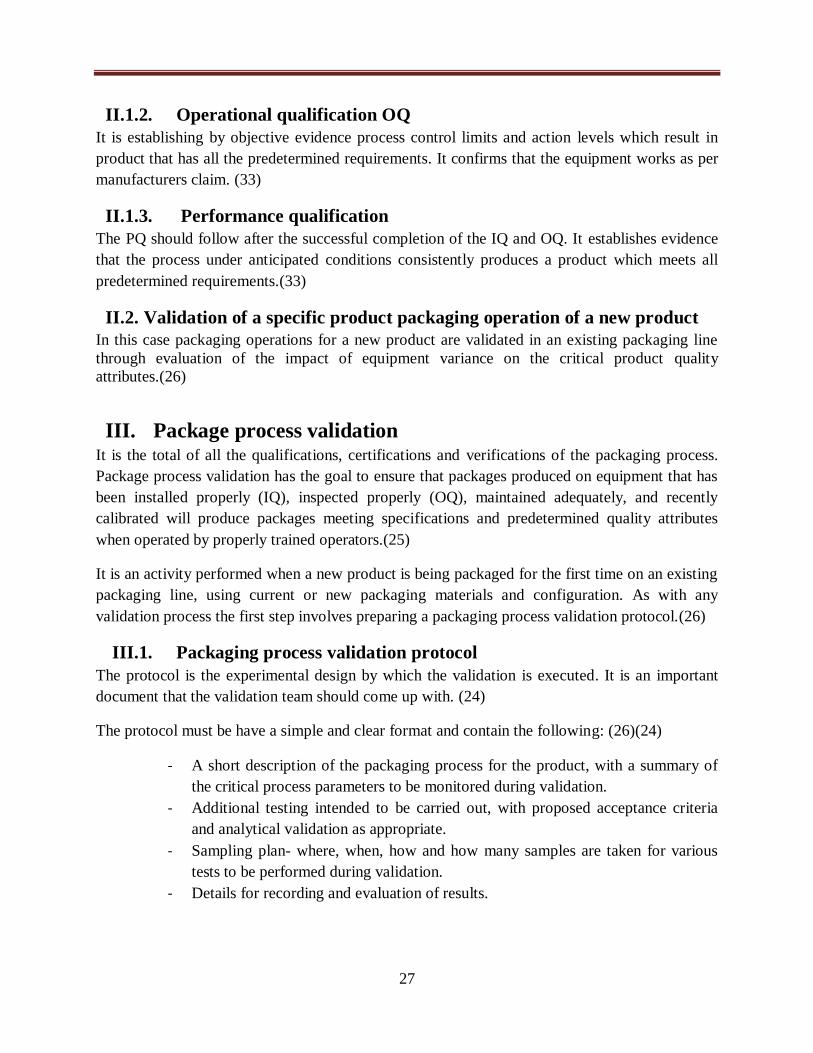
the validation of packaging by the method water …
TRANSCRIPT
بيةـــعــــة الشــراطيــــــة الديمقـــة الجزائريـــــهوريـــمـــالج
République Algérienne Démocratique et Populaire
DEPARTEMENT OF PHARMACY
THEME :
THE VALIDATION OF PACKAGING BY THE METHOD WATER
VAPOUR TRANSMISSION RATE
Presented by:
MAWADZE Euphrasia
Defended on 10 /07/2019
Jury
President:
Pr HAREK Yahia Professor in Analytical chemistry
Members:
Dr GUENDOUZ Souhila Senior Lecturer in Pharmacy Galenic
Dr KADDOUR Faiza Senior lecturer in Pharmacy Industrial
Mr. BERKANI Khaled General Site Director of Continental Pharm
Supervisor
Dr BENATTA Dalila Senior lecturer in Pharmacy Galenic
Co-supervisor: Mr BERKANI Khaled General Site Director Of Continental Pharm
MINISTRY OF HIGHER EDUCATION AND SCIENTIFIC RESEARCH
UNIVERSITY ABOU BEKR BELK AÎD
FACULTE DE MEDECINE
DR . B. BENZERDJEB - TLEMCEN
وزارة الــــــــــتعـــليم العــــالــــــــــــي
والبـــحث العـــــــــــــــلمـــــــــي
جــامعة أبو بكــر بلـقـا يد
الطبكـليــة
د. ب. بن زرجــب – تلمســان
DISSERTATION FOR THE OBTENTION OF THE DOCTOR OF
PHARMACY DEGREE

i
Acknowledgements
I would like to express my profound gratitude to Dr.Benatta Dalila, my supervisor for her
unwavering support, supervision, guidance and patience throughout the course of this research
project. She gave me an opportunity to work in the pharmaceutical industry field and transmitted
to me a passion for industrial pharmacy. Her support was always there when ever I needed it.
My sincere gratitude to the technical director of Continental Pharm Laboratories Mr Khalid
Berkani, for his warm welcome, help, generosity and assistance during the internship.
I would also like to thank Mr Mohammed Bouyaed and Miss Amel Turki the quality assurance
team for their guidance, assistance and all the information that they gave to me.
Not forgetting Miss Sara the production site supervisor, Inam, Bouchra, Chahrazed and the
entire staff from the production site, maintenance and the quality control laboratory who
enriched my knowledge on the manufacturing process of drugs in the industry.
To Mr Aziz and Madam Nabila for their kindness, assistance and good humour from the very
first day of the internship right till the end.
I thank the entire staff at continental pharm, who helped in the research of this project.
My immense appreciation goes to Pr Harek Yahia, Professor in analytical chemistry, for
honouring me by presiding over the jury for this thesis.
I also express my gratitude towards the members of the jury:
Dr Guendouz Souhila
Senior lecturer in Pharmacy Galenic
Dr Kaddour Faiza
Senior lecturer in Pharmacy Galenic
I thank them for accepting to be part of the jury that examines and judges this work, I give to
them my utmost respect and acknowledgement.
Lastly and most importantly I give my praise, glory and honour to the ALMIGHTY GOD, our
LORD JESUS CHRIST for without Him, I would not be here. It is through Him and by His
grace that I have come this far.

ii
Dedications
I dedicate this thesis to:
My dear parents: Mr and Mrs J.V Mawadze
For their love, sacrifice, support and guidance, I am forever grateful. Thank you for all that you
have done for me, no words can express the love, respect and honour I have for you. There is
nothing in this world that I can give you that is worth all the effort you put in day and night
towards our education and well being. You taught me the importance of education, hard work
and sacrifice. This success I give back to you, it is the fruit of all your prayers, unfailing support,
sacrifices and encouragements.
May God bless you and grant to you many more years of good health to enjoy the fruits of your
labours.
My older sisters: Letwin, Ratidzo, Yeukai and Keron
You are more than just sisters to me; you are my second mothers and my best friends. I am
thankful for your love, support, encouragement and sacrifices throughout my life. You are my
source of inspiration and in the footsteps you leave behind i will follow.
My young sister: Tendai
My best friend, thank you for taking your time to listen to me. I am grateful for your love,
support and care.
My brothers in-law: Charles, Dingani and Artwell
I am grateful for your love, support, sacrifices and encouragement. You have stood by me
throughout my studies. You are the best sons that God blessed my parents with and the best
brothers i could ever ask for. May God bless you richly.
To Moses Chihota
I am thankful for your love, support, care and prayers.
To my dear friends Thamari, Leona, Linnety, Charity, Marjorie and Lukundo thank you for
your prayers and the good times we spend together.
To everyone that is dear to me, and those that remembered me in their prayers.
MAWADZE Euphrasia
iii
Table of contents
Acknowledgements..........................................................................................................................i
Dedications......................................................................................................................................ii
Summary.........................................................................................................................................iii
Lists of figures...............................................................................................................................vii
Lists of tables................................................................................................................................viii
Abbreviations..................................................................................................................................ix
Glossary ..........................................................................................................................................x
Introduction......................................................................................................................................1
First Part: Theoretical research
Chapter I: Packaging
I. Generalities .....................................................................................................................6
I.1. Definitions........................................................................................................................6
II. Functions and properties of effective packaging ...........................................................6
III. Selection of packaging materials ................................................................................7
IV. Types of packaging......................................................................................................7
IV.1. Primary packaging .....................................................................................................8
IV.1.1. Primary packaging materials and closures ..........................................................8
IV.1.2. Types of containers used as primary packaging: ............................................... 14
IV.2. Secondary Packaging ............................................................................................... 17
IV.3. Tertiary packaging ................................................................................................... 17
V. Regulation of pharmaceutical packaging .................................................................... 18
V.1. The pharmacopoeias: ..................................................................................................... 18
V.2. FDA Packaging Guidelines ............................................................................................ 19
V.3. International Organization for Standardization (ISO) ..................................................... 19
V.4. International conference on harmonization (ICH) ........................................................... 19
VI. Quality control of primary packaging material ....................................................... 20
VI.1. Sampling ................................................................................................................. 20
VI.2. Test controls for primary packaging materials ......................................................... 21
VI.2.1. Identification test: ............................................................................................. 21
VI.2.2. Mechanical tests: .............................................................................................. 21
iv
VI.2.3. Transparency tests: ........................................................................................... 21
VI.2.4. Permeability tests: ............................................................................................ 21
VI.2.5. Preservation tests: ............................................................................................. 22
VI.2.6. Chemical resistance tests: ................................................................................. 22
Chapter II: Validation of pharmaceutical packaging
I. Generalities ................................................................................................................... 24
I.1. Definition of validation................................................................................................... 24
I.2. Types of validation ......................................................................................................... 24
I.2.1. Retrospective validation .......................................................................................... 24
I.2.2. Prospective validation.............................................................................................. 25
I.2.3. Concurrent validation .............................................................................................. 25
I.2.4. Revalidation ............................................................................................................ 25
I.3. The various validation parameters .................................................................................. 26
I.4. Interest of packaging validation ...................................................................................... 26
II. Key elements of packaging validation activity ............................................................ 26
II.1. Qualification of new packaging equipment ..................................................................... 26
II.1.1. Installation qualification IQ ..................................................................................... 26
II.1.2. Operational qualification OQ ................................................................................... 27
II.1.3. Performance qualification ........................................................................................ 27
II.2. Validation of a specific product packaging operation of a new product ........................... 27
III. Package process validation ....................................................................................... 27
III.1. Packaging process validation protocol ..................................................................... 27
III.2. Validation master plan (VMP) ................................................................................. 28
III.3. Validation report ..................................................................................................... 28
Chapter III: Verifying the integrity of pharmaceutical packaging
I. Generalities ................................................................................................................... 30
I.1. Definition of package integrity ....................................................................................... 30
v
I.2. Importance of testing for package integrity ..................................................................... 30
II. Methods for testing package integrity ......................................................................... 30
II.1. Destructive test methods- container closure integrity tests .............................................. 31
II.1.1. Blue dye penetration test.......................................................................................... 31
II.1.2. Tracer gas test ......................................................................................................... 31
II.1.2.1. Bomb test...................................................................................................... 31
II.2. Non destructive test methods- container closure integrity tests. ....................................... 32
II.2.1. Vacuum decay ......................................................................................................... 32
II.2.2. Force decay ............................................................................................................. 33
II.3. Water vapour transmission rate test ................................................................................ 33
II.3.1. Definition WVTR .................................................................................................... 33
I.3.3.2.1. Importance of measuring WVTR .................................................................. 33
II.3.3. Methods of measuring WVTR ................................................................................. 34
II.3.4. Comparison of the gravimetric method and the automated testing methods .............. 36
Second Part: Practical research
I. Introduction .................................................................................................................. 39
I.1. Objectives of study ......................................................................................................... 39
Secondary objectives:......................................................................................................... 39
I.2. Type of study: ................................................................................................................ 39
I.3. Place where the study was conducted.............................................................................. 39
I.3.1. Presentation of Continental Pharm Laboratories (CLP) ............................................ 39
I.3.2. Organisation of CLP ................................................................................................ 40
I.4. Motivation of theme ....................................................................................................... 42
II. Materials and equipment used ..................................................................................... 42
II.1. Materials used ................................................................................................................ 42
II.1.1. Types of materials used in primary packaging at CLP .............................................. 43
I.1.2. Quality control of raw materials............................................................................... 44
II.2. Equipment used .............................................................................................................. 44
II.2.1. Automatic blister machine (thermo former) - NMX ................................................. 45

vi
II.2.2. Powder filling and capping machine- RAV 05 ......................................................... 50
II.2.3. Bell shaped vacuum with pump ............................................................................... 53
III. Method....................................................................................................................... 53
III.1. Establishing procedures ........................................................................................... 53
III.2. Execution of the adjustments of the packaging machines ......................................... 53
III.3. Preparation of samples ............................................................................................. 54
III.3.1.Preparing samples of sealed bottles .......................................................................... 54
III.3.2.Preparing samples of blister packs ........................................................................... 54
IV. Results ....................................................................................................................... 56
IV.1. Procedure of adjustment of RAV 05 - powder filling and capping machine ............. 56
IV.2. Procedure of adjustment of the NMX- blister machine ............................................. 64
IV.4.3. Procedure of the method WVTR .............................................................................. 67
IV.4. Verification of conditions during the sample preparation process ............................. 70
IV.4.1. Normal values of temperature and humidity in the room ................................... 70
IV.4.2. Results of adjustment of the blister machine NMX ........................................... 70
IV.4.3. Results of the adjustment of the powder filling and capping machine ............... 71
V. Discussion...................................................................................................................... 73
Conclusion............................................................................................................................. .......76
Bibliography.................................................................................................................................78
Annexes ................................................................................................................... .....................81
Abstract.........................................................................................................................................94

vii
List of figures
Figure 1: Plastic thread screw cap...............................................................................................13
Figure 2: Rubber stoppers............................................................................................................13
Figure 3: Plastic pilfer proof closure on a container....................................................................14
Figure 4: Roll on closures............................................................................................................14
Figure 5: Well closed container...................................................................................................14
Figure 6: Airtight container.........................................................................................................15
Figure 7: Single dose containers.....................................................................................…..........15
Figure 8: Multiple dose containers...............................................................................................15
Figure 9: Strip packages...............................................................................................................16
Figure 10: Blister package............................................................................................................16
Figure 11: Sachet of Paracetamol powder for oral solution ........................................................17
Figure 12: Collapsible tub............................................................................................................17
Figure 13: Bell shaped chamber connected to a vacuum pump...................................................31
Figure 14: The two types of the tracer gas test...........................................................................32
Figure 15: Vacuum decay test chamber......................................................................................32
Figure 16: The two types of gravimetric wvtr testing..................................................................34
Figure 17: Dynamic relative humidity tester................................................................................35
Figure 18: The testing principle of the electrolytic method.........................................................36
Figure 19: Calcium test principle.................................................................................................36
Figure 20: Administrative chart of CLP.......................................................................................41
Figure 21: Glass container............................................................................................................42
Figure 22: Plastic cap....................................................................................................................43
Figure 23: Front and back view of blister packs...........................................................................43
Figure 24: NMX blister packing machine....................................................................................45
Figure 25: Image of the sea vision control of the blister machine................................................46
Figure 26: Flowchart diagram of primary packaging on the blister machine...............................49
Figure 27: RAV 05 bottle filling and capping machine................................................................50
Figure 28: Flowchart diagram of packaging on the powder filling and capping..........................52
Figure 29: Bell shaped vacuum with pump..................................................................................53

viii
List of tables
Table I: Types of raw materials used in primary packaging..........................................................8
Table II: Types of glass, their composition, properties and uses.................................................10
Table III: Adjustments performed on the powder filling and capping machine..........................58
Table IV: Optimised adjustments on the powder filling and capping machine............................58
Table V: The number of adjustments with tightening head fixed at one position........................59
Table VI: Record of torque-metre measurements and integrity tests...........................................60
Table VII: Normal room temperature and pressure......................................................................70
Table VIII: Results of the control of the blister machine.............................................................70
Table IX: Results of the control of the blister samples.................................................................71
Table X: Results of the control of the powder filling and capping machine................................71
Table XI: Results from the control of bottle samples...................................................................72

ix
List of abbreviations
API: Active Pharmaceutical Ingredient
ASTM: American Society of Testing and Materials
CLP: Continental Pharm Laboratories
FDA: Food and Drug Administration
GMP: Good manufacturing practices
HDPE: High Density Polyethylene
GRAS: Generally Regarded As Safe
ICH: International Conference on Harmonization
ISO: International Organization of Standardization
LDPE: Low Density Polyethylene
LOD/LOQ: Limit of Detection/ Limit of Quantitation
PET: Polyethylene terephthalate
PVC: Polyvinyl Chloride
PVDC: Polyvinylidene dichloride
QC: Quality Control
TAPPI: Technical Association of the Paper and Pulp Industry
USP: United States Pharmacopeia
WVTR: Water Vapour Transmission Rate

x
Glossary
Accuracy
The accuracy of an analytical method is the closeness of the test results obtained by that method
to the true value.
Active pharmaceutical ingredient
It is the ingredient in a pharmaceutical drug that is biologically active.
American Society for Testing and Materials
It is an international standards organization that develops and publishes voluntary consensus
technical standards for a wide range of materials, products, systems, and services
Food and Drug Administration
It is a federal agency of the United States Department of Health and Human Services. It is
responsible for protecting and promoting public health through the control and supervision of
food safety, tobacco products, dietary supplements, prescription and over the counter
pharmaceutical drugs.
Good Manufacturing Practices
The good manufacturing practices indicate a token of applied quality in the manufacture of drugs
for human or animal use. They guarantee a coherent manufacture and control of products and
according to the quality standards adapted to their use.
Hydrolytic resistance of glass
The hydrolytic resistance of glass refers to its chemical durability, or in other words how likely a
glass object is to cause contamination to the samples inside.
International Conference on Harmonization ICH
The International Council for Harmonization of Technical Requirements for Pharmaceuticals for
Human Use (ICH) is an initiative that brings together regulatory authorities and pharmaceutical
industry to discuss scientific and technical aspects of pharmaceutical product development and
registration.
International organization for standardization ISO
The International Organization for Standardization is an international standard-setting body
composed of representatives from various national standards organizations.
Limit of detection LOD

xi
It is defined as the lowest concentration of an analyte in a sample that can be detected, not
quantified.
Limit of quantitation LOQ
The Quantitation Limit is the lowest concentration of an analyte in a sample that can be
determined with acceptable precision and accuracy under the stated operational conditions of the
analytical procedures.
Procedure
It is a specified way of accomplishing an activity or a process
Quality assurance
It is a system of all actions taken with the objective of assuring that all the active materials have
the required quality for their specified use and that all quality systems are maintained.
Robustness/ruggedness
It is a measure of capacity to remain unaffected by small but deliberate variations
Shelf life
It is the period of time, from the date of manufacture, that a drug product is expected to remain
within its approved product specification while stored under defined conditions.
Technical association of the pulp and paper industry TAPPI
It is a registered non profit, international Non-Governmental Organization of about 14,000
member engineers, scientists, managers, academics and others involved in the areas of pulp, and
paper, it also includes members of some allied areas of packaging (such as corrugated fiber
board, flexible packaging, lamination, adhesives, coatings and extrusion).
Weathering/ Blooming
It is when moisture condenses on the surface of a glass container and extracts some weakly
bound alkali leaving behind a white deposit of alkali carbonate; further condensation of moisture
will lead to the formation of an alkaline solution which will dissolve some silica resulting in loss
of brilliance from the surface of the glass.

Introduction

2
A decade ago packaging often was an afterthought for many pharmaceutical companies, viewed
as merely the final step in manufacturing. But now firms must consider packaging earlier during
the development process, it has become an integral part of any pharmaceutical industry.
Packaging is the process by which the pharmaceuticals are suitably packed so that they should
retain their therapeutic effectiveness from the time of packaging till they are consumed. It is a
broad process and a multifaceted task. It has the responsibility to deliver life saving drugs in
every dosage form, therefore the composition and quality of the packaging materials that are
used can have a critical impact on the performance, function, and production cost of
pharmaceutical medications or drugs. Improper packaging can cause the active pharmaceutical
ingredients (API) in medications to degrade faster, and have shorter shelf lives.
The packaging processes and equipment need validation and qualification in the same way as
any other part of processing within a pharmaceutical facility. The notions of qualification and
validation are regulatory requirements and represent the pillars of quality assurance. The
qualification of equipment and installations confirms that the GMP requirements have been
achieved, while validation allows the control of different processes.
There are various tests for the determination of quality, integrity and compatibility of packaging
materials to assure production of drugs of good quality. Tests applied to packing material can be
chemical, mechanical or environmental. The chemical tests include alkalinity of glass, pH value
of materials and compatibility test with the medicament, while those for environment test for
absorption of water, permeability to water, vapour or gases and characteristics such as light
transmission.
Many drugs are moisture sensitive so controlling water vapour into or out of a package is crucial
to maintain quality of drug. Scrupulous quality control during the manufacturing, preparation and
handling stages becomes squandered effort if the packed drug is not protected against moisture
vapour that contributes to its deterioration, shortened shelf life or renders it unfit for sale or
consumption. The ability of packaging to protect against moisture can be ascertained by
performing various tests during production, as part of the in process controls and after
production.
Manufacturers do their best to provide and assure protective packaging for moisture sensitive
drugs, however due to constraints sometimes beyond their control; the drug can fail to meet its
expected shelf life. This was seen in the packaging of Clavodex tablets and powder at
CONTINENTAL PHARM LABORATORIES (CLP). The manufacturer at first ascertained the
integrity of Clavodex package using the dye penetration test method. This test method was not
adequate enough to validate the packaging as there were product reclamations despite the test

3
results conforming to the required outcomes. This propelled the manufacturer to propose a study
with a more rigorous test method and to collaborate with a testing company abroad.
Our main concern is that can the manufacturer get to the point of validating the packaging used
for Clavodex using the Water Vapour Transmission rate (WVTR) method and what are the steps
to follow in order to prepare samples to carry out this test?
The aim of this research is to establish and validate a protocol of sample preparation and
approbation of WVTR tests for Clavodex tablets and powder for oral solution produced at CLP.
The research will be presented in two parts:
The first part is a theoretical approach to pharmaceutical packaging; it is gives a review of the
different aspects of packaging: the types of packaging and packaging materials, the regulations
of packaging, the validation of packaging as well as the test methods used to test and validate the
integrity of the package.
The second part it is a practical industrial approach to package validation at the pharmaceutical
industry Continental Pharm Laboratoires (CLP) in the packaging of Clavodex. It has a brief
description of the research and the pharmaceutical industry CLP, an outline of the primary
packaging lines at CLP, the equipment and their description and operation. It also describes the
adjustments to be done on the machines before and during the preparation of samples and the
preparation of the samples for testing. Finally we established the procedures for the adjustments
of the packaging machines and the procedure for preparation of samples according to the WVTR
method. A discussion of the results and a conclusion will finalise the study.

Theoretical
research

Chapter I:
Packaging

6
I. Generalities
Packaging is designed to contain a product so that it is unable to interact with the environment; it
is both art and science of protecting or enclosing a product. The quality of packaging plays an
important role in maintaining the quality of a drug during storage, transportation, delivery, sale
and use.(1)(2)
I.1. Definitions
Packaging has been defined in different ways, because of its perceived numerous functions. It
has been defined as the art, science and technology of preparing products for sale in a cost
effective manner. In the context of a pharmaceutical product “preparing products for sale” means
having a role in preserving and protecting the drug from contamination or degradation, ensuring
that the drug retains its therapeutic effectiveness from the time of packaging till they are used, as
well as in the presentation and identification of the drug.(3)(4)
The term packaging also covers a set of operations, including filling and labelling, that a bulk
product has to undergo in order to become a finished product.(5)
II. Functions and properties of effective packaging
There are various functions of packaging which can be divided into primary and secondary
functions. The primary functions concern the technical nature of the packaging and the
secondary functions relate to communication of information to the patient about the use of the
drug and the storage conditions.
Containment
The containment of the product is the most fundamental function of packaging for medicinal
products. The design of high-quality packaging must take into account both the needs of the
product and of the manufacturing and distribution system. This requires the packaging not to
leak, nor allows diffusion and permeation of the product; to be strong enough to hold the
contents when subjected to normal handling; not to be altered by the ingredients of the
formulation in its final dosage form. (6)
Protection
The packaging must protect the product against all adverse external influences that may affect its
quality or potency, such as: light, moisture, oxygen, biological contamination, mechanical
damage. Besides protecting the drug form external factors, the packaging should not interact
with it so as to introduce unacceptable changes. The compatibility of the packaging with the
active pharmaceutical ingredients is very important in maintaining integrity of the product. In
addition it must preserve the physical properties of all dosage forms, not alter the identity of the
drug, and preserve the characteristic properties of the drug so that the latter complies with its
specifications. (6)(2)

7
Presentation and Transmission of information
Packaging is also an essential source of information on medicinal products. Information is
provided by labels and package inserts, which communicate how to use, transport, dispose, store
and recycle the product. Labelling may help to reinforce the instructions given by the physician
or the pharmacist, and improve compliance with drug therapy. In this respect, packaging
becomes a compliance aid. (2)
Preservation
Preservation in this context means inhibiting chemical and biological changes. A common
example would be the active pharmaceutical ingredients remaining within their specified limits
over the shelf life of the pharmaceutical product. The question of whether a packaging will
provide the required protection for the pharmaceutical product and the required stability over a
certain time period can only be answered by means of real-time stability studies.(6)(7)
Convenience
This means all aspects of the movement and use of the product from the packaging line to final
use and disposal. Packages can have features that add convenience in handling, distribution,
opening, closing, use and reuse.(2)
III. Selection of packaging materials
The quality of the packaging material plays a very important role in the quality of the
pharmaceutical products. The choice of primary or secondary packaging materials will depend
on the degree of protection required, compatibility with the contents, filling method and cost.
(4)(6)
The packaging materials used should possess the ideal characteristics such as: (2)
1) Protection from environmental conditions such as humidity, temperature.
2) The product packed in the container must be non-reactive to the container enclosing it.
3) The odour and the taste of the product must not be altered.
4) The packaging material must be non-toxic.
5) FDA approved packaging materials must be used.
6) They must meet applicable tamper-resistance requirements
7) They must have reasonable cost in relation to cost of the product
IV. Types of packaging
Pharmaceutical packaging is classified into 3 different types in terms of its role towards the
semi-open product:

8
IV.1. Primary packaging
The primary package is the material in direct contact with the dosage form. Its main role is to
protect the formulation from environmental, chemical, mechanical and other hazards from the
last step of production until it is used, while also being compatible with the product.(1)
The material in direct contact must not interact chemically or physically with the drug in such a
way that will affect the quality above the tolerated limits set by regulatory authorities. This phase
of primary packaging, where the semi-open product is going to be placed in its envelope of
protection is delicate and still in contact with the outside environment.(8)
IV.1.1. Primary packaging materials and closures
In accordance with the methods of use and administration of pharmaceutical products, packaging
materials vary a great deal and have to meet a great variety of requirements. The most commonly
used materials are glass, plastic, rubber, paper and metal.(6)
Table I: Types of raw materials used in primary packaging (6)
Types of materials used Uses
Glass Ampoules
Bottles Vials
Syringes
Cartridges
Plastic Closures
Bottles
Bags Tubes
Laminates with paper or foil
Metal Collapsible tubes Rigid cans
Foils
Gas cylinders Needles
Pressurized containers
Rubber Closures including plungers
The following is a review of the principal materials which are commonly used in primary
packaging, which is enough to give an idea of the problems caused by the choice of packaging
materials in pharmacy:

9
IV.1.1.1. Glass:
It is used for a large number of pharmaceuticals including medicinal products for oral and local
use as the first choice. Different types of glass may be necessary, depending on the
characteristics and the intended use of product concerned.(6)
In the European and United States Pharmacopeias various grades of glass are classified
according to their chemical characteristics and efficacy within the packaging of pharmaceuticals.
Its distinction when compared to other packaging materials lies in the unique combination of
durability, inertness and transparency. Glass is the only packaging material rated generally
regarded as safe (GRAS) by the Food and Drug Administration. (9)
It is mostly used because of its particular properties which are: hardness; transparency; stability;
chemical inertness and easy to clean.(10)
IV.1.1.1.1. Types of glass
According to the hydrolytic resistance glass is classified as follows:
a. Type-1: Borosilicate glass.
This is a neutral glass with a high hydrolytic resistance due to the chemical composition of the
glass itself. Type 1 glass containers are suitable for most preparations whether or not for
parenteral preparations.(8)
b. Type -2: Treated soda lime glass.
It has a high hydrolytic resistance resulting from suitable treatment of the surface. The surface of
the glass is treated to remove surface alkali, this process is known as sulphur treatment and it
prevents weathering of empty bottles. Weathering /blooming is the dissolving of the salts out of
the glass when it is exposed to moisture. The treatment renders the glass more chemically
resistant by neutralizing the alkaline oxides on the surface.(4)
The containers made from this type of glass are suitable for most acidic and neutral aqueous
preparations whether or not for parenteral use.(8)
c. Type-3: Regular soda lime glass.
This is untreated glass with a moderate hydrolytic resistance. Containers made from this glass
are suitable for non-aqueous preparations for parenteral administration, for powders for
parenteral administration and for preparations not for parenteral administration.(8)
d. Type- 4: Non Parenteral general purpose soda lime glass.
As the name indicates this type of glass is used to store non parenteral formulations, those
intended for oral or topical use.(4)

10
Table II: types of glass, their composition, properties and uses (4)
Type of glass Main constituents Properties Uses
Type -1
Borosilicate glass
Example Pyrex,
borosil
SiO2 80%
B2O3 12%
Al2O3 2%
Na2O +CaO 6%
-has high melting point
so can withstand high
temperature.
-Resistant to chemical
substances.
-reduced leaching
action
-laboratory glass
apparatus
-for injections and for
water for injection
Type-2
Treated soda-lime
glass
Made of soda lime
glass. The surface of
which is treated
with acidic gas lie
SO2 (dealkalised) at
elevated temperature
(5000 C) and
moisture
The surface of the glass
is fairly resistant to
attack by water for a
period of time.
Sulfur treatment
neutralizes the alkaline
oxides on the surface,
thereby rendering the
glass more chemically
resistant
Used for alkali
sensitive products,
infusion fluids, blood
and plasma.
Large volume
container
Type-3
Regular soda-lime
glass
SiO2
Na2O
CaO
It contains high
concentration of
alkaline oxides and
imparts alkalinity o
aqueous substances.
Flakes easily.
May crack due to
sudden change of
temperature.
For all solid dosage
forms( for example:
tablets, powders)
For oily injections.
Not to be used for
aqueous injection.
Not to be used for
alkali-sensitive drugs.
Type -NP
Non-parenteral
glass or general
purpose soda lime
glass
For oral and topical
purpose.
Not for ampoules.

11
IV.1.1.2. Plastic
Plastics are synthetic polymers of high molecular weight. The general advantages of using plastic
materials in pharmaceutical packaging include consumer acceptance, preference, excellent safety
characteristics (non fragility), less weight than other materials, moisture barrier properties, gas
barrier properties, good puncture resistance, low heat conductivity, good sealant properties, and
recyclability. (9)
They may contain some additives for example: antioxidants; stabilizers; plasticizers; lubricants;
colouring matter and impact modifiers. The nature and amount of the additives are determined
by the type of the polymer, the process used to convert the polymer into the container and the
intended purpose of the container. (8)
IV.1.1.2.1. Types of plastics:
a. Polyethylene :
It is the most used polymer in packaging. Its properties differ according to degree of crystallinity,
molecular mass, the ramification, and also the process of fabrication. There are two forms of
polyethylene: (10)
i. Low density polyethylene or high pressure polyethylene: these require
temperatures of 150 to 250 ° C and a pressure of 1 200 to 1 500 bars for
their fabrication. Their molecular mass varies from 10 000 to 30 000 and
their density 0.91 to 0.92.
ii. High density polyethylene or low pressure polyethylene: it has a higher
molecular mass (10 000 to 50 000), therefore making it more dense than the
low density polyethylene. It has the advantage of being less permeable to
water vapour and gases because of its high density and is mostly used in
drug packaging because it offers a good barrier against moisture.
It is mostly used in preparation of plastic bags, plastic films and bottles.
b. Polypropylene
It is also popularly used in pharmaceutical containers, and has properties close to those of
polyethylene but it resists oils and fats better. It is most commonly used for making syringes. It is
also suitable for sterilization at high temperature because of its high melting point. (11)
c. Polyvinylchloride (PVC)
It is the third mostly used plastic after polyethylene and polypropylene. It has a poor heat
stability, and lower melting point than the other two. It can be made softer and flexible by the
addition of plasticizers. It is mostly used for making containers used for blood and blood
components.(11)

12
d. Polyamide (nylon)
It is made artificially by the interaction of a diamine and a dicarboxylic acid. It has a good
chemical resistance, high strength, high heat resistance and good water resistance. It is
impermeable to odours and gases and is not toxic.(11)(10)
Its main application in the packaging area is in laminates.(12)
e. Polystyrene
It is a plastic obtained by the polymerization of styrene. It is resistant to acids, base, alcohol s
and to oils. It is used in packaging for bottles or rigid tubes.(10)
IV.1.1.2.2. Permeability of plastic to water vapour
The permeation of plastic materials by oxygen and water vapour are always a concern in
choosing and specifying a plastic material to protect a drug. All plastic materials even those
coated with a high barrier material exhibit some degree of permeability compared with glass or
metal. The permeability of PVC water vapour is low; it is around 3g/m2/24h whilst that of
PVDC is reduced 5 -10 times.(13)
IV.1.1.3. Metal
Metal containers are used solely for medicinal products for non parenteral administration. Since
metal is strong, impermeable to gases and shatter proof, it is the ideal packaging material for
pressurized containers.(9)
The metals that are mostly used in packaging are:
IV.1.1.3.1. Aluminium:
Aluminium foil is the most commonly used packaging material due to its protective
characteristics with respect to the effects of moisture, heat and light.(9) It is used in aluminium
ointment tubes; screw caps; aluminium strips for strip packaging of tablet, capsules .(4)
IV.1.1.3.2. Tin:
It is the most expensive amongst all the other metals used for pharmaceutical packaging. It has
the advantages of being chemically inert and has a good appearance.(11)
It is mainly used for eye ointment still packaged in pure tin ointment tubes.(4)
IV.1.1.4. Rubber
Rubber is mainly used for the manufacture of closures. It is in 2 forms; natural rubber and
synthetic rubber. Synthetic rubber is the type mostly used in the pharmaceutical field. It is
generally more resistant to ageing and more impermeable to gases and water vapour(10).
Examples of synthetic rubber are: butyl rubber which has a low permeability to water and low
water absorption; nitrile rubber ; Chloroprene rubber(1)

13
IV.1.1.5. Closures
Closures are the most critical component of a pharmaceutical container. An effective closure
system prevents the loss of material from the container, prevents contamination of product and
prevents loss or entry of moisture. It must also be easily removed and replaced. (14)(11)
Depending on the type of the container, closures may have different shapes and sizes. For a
closure system to be effective it is essential to consider the nature of material of container,
properties of the product and the stability requirements(9).
IV.1.1.5.1. Types of closures:
The basic types of caps and closures include:
a) Thread screw
They are made of metal or of plastic. As the name indicates they contain threads which get
engaged with threads on the neck of the container. These types of closures provide the effective
seal which protect the product from physical and chemical reaction. Plastic caps are more
popular than metal because plastic are resistant to corrosion. (11)
b) Rubber closures
These closures do not pose any problem and can be used in contact with a large number of drug
preparations.(9)
c) Pilfer proof closure
This differs from standard roll on closure in that it has a longer skirt length. When this closure
breaks at the bridge, the bank remains at the neck of the container. The closure can be resealed
but the broken bank indicates the seal has been broken (9)
Figure 1: plastic thread screw cap (11)
Figure 2: rubber stoppers (11)

14
d) Roll on closures
Roll on closure contains the aluminium roll on cap which can be easily sealed, opened and
closed. These are available in re sealable, non- sealable & pilfer proof type forms.
IV.1.2. Types of containers used as primary packaging:
A container for pharmaceutical use as defined by the European pharmacopeia is an article that
contains or is intended to contain a product and is, or may be in direct contact with it. (8)
IV.1.2.1. Primary package for liquid orals
IV.1.2.1.1. Well closed containers
These types of containers provide the protection from shocks, contamination by foreign particles
and loss of article under normal conditions of handling, storage and distribution.(2)
Examples: ampoules; vials
The type of material mostly used for this type of container is glass.
IV.1.2.1.2. Air tight containers:
They are impermeable to solids, liquids and gases under ordinary conditions of handling, storage
and distribution. If these containers are intended to be opened on more than one occasions then
they remain airtight after reclosing.(2)
Examples: bottles used for storing pills
The type of material which is mostly used is plastic.
Figure 3: plastic pilfer proof closure on a container (11)
Figure 4: roll on closures (11)
Figure 5: well closed containers (11)

15
IV.1.2.1.3. Hermetically sealed containers:
A sealed container is a container closed by fusion of the material of the container. These cannot
be opened on more than one occasion like the air tight containers. (8)
This type of container is not affected by air and other gases under normal conditions of handling,
storage and transport.(14)
Hermetically sealed containers can be divided into 2 types:
a) single dosed container
These are intended for articles for parenteral administration and they are designed to hold single
dose. They are mostly made of glass and plastic.(11)
Example: ampoules
b) multiple dose container
This type of container holds multiple doses and their contents are withdrawn at various intervals.
It allows withdrawal of successive portions of the contents without changing the quality, strength
or purity of remaining portion.
Example: vials
Figure 6: air tight container (4)
Figure 7: single dose containers (4)
Figure 8: multiple dose containers. (4)

16
IV.1.2.2. Primary package for solid dosage forms:
IV.1.2.2.1. Strip package
The package is made up of two layers of film. A strip package contains many pockets and
each pocket contains single dose of drug.(2) It is a form of unit dose packaging that is commonly
used for the packaging of tablets and capsules in length. Different packaging materials are used
for strip packaging such as paper, polyethylene, foil and polyethylene lamination.(4)
IV.1.2.2.2. Blister package
It is made up of base layer (polyvinylchloride layer) with cavities which contain pharmaceutical
product. It provides greater protection then strip package. It contains a lid which is made up of
aluminium and paper foil.(15)
IV.1.2.2.3. Sachet
Sachets can be fabricated from a single web with a centre fold, using a three or four sided seal or
two webs using a four sided seal.(16)
The material of construction can consist of several layers that are individually selected based on
their performance characteristics. A typical construction consists of an inner most heat seal layer,
which is also the product contact layer. The heat seal layer is designed to bond to itself when
heat is applied during the forming process. In addition to the heat seal layer, a barrier layer is
commonly included to provide protection from the external environment. Aluminium foil is
considered to be the most protective against gas and moisture ingress as well as protection from
light transmission. They are mostly used in packaging of powders for oral solution. (17)
Figure 9: strip packages (4)
Figure 10: blister package (11)

17
IV.1.2.3. Primary package for semi solid dosage forms
Semi solid dosage forms include ointments, creams and pastes. The containers used for semi
solid dosage forms include tubes and plastic containers.(2)
IV.2. Secondary Packaging
The package external to primary package is known as secondary package. It is the package in
which the primary package is placed and is not in direct conduct with the medicament. This
package provides additional protection during warehousing and also provide information about
drug product.(1)
Functions (1)
- Protect the flexible containers.
- Protection from tough handling during transportation.
- Provide information of the dosage form and the volume or number of times to take the
medicament on a label.
- It holds the notice and can contain accessories for example a plastic measuring cup for
liquid oral forms.
Examples: cartons, boxes
IV.3. Tertiary packaging
It provides bulk handling and shipping of pharmaceuticals from one place to another.(14) It is the
outer package of secondary packaging and prevents damage to the products. It is used for bulk
handling and shipping.(1)
Examples: Barrel, crate, container, pallets, slip sheet.
Figure 11: sachet of paracetamol powder for oral solution
(56)
Figure 12: collapsible tube(11)

18
V. Regulation of pharmaceutical packaging
As the pharmaceutical industries throughout the world are moving ahead towards producing
drugs of better quality and becoming more and more competitive, regulatory agencies are being
established in various countries across the globe. Regulatory authority and organizations are
responsible in effective drug regulation required to ensure the safety, efficacy and quality of
drugs, as well as the accuracy and appropriateness of the drug information available to the
public. (18)
Given the link between the quality of a pharmaceutical product and the quality of its packaging,
pharmaceutical packaging materials and systems must be subject, in principle, to the same
quality assurance requirements as pharmaceutical products. Regulations on packaging are
intended to help the manufacturer produce products of good quality. (19)
Some of the regulatory agencies and organizations that regulate pharmaceutical packaging
include:
- Food and Drug Administration (FDA)
- The pharmacopoeias
- International Organization for Standardization (ISO)
- International conference on harmonization (ICH)
- ASTM
- Technical association of the pulp and paper industry (TAPPI)
V.1. The pharmacopoeias:
The European and United States pharmacopoeias all describe materials of the same type, but
there are considerable differences in the classification and presentation. The European
pharmacopoeia is the most detailed and requires tests in relation to the use and routes of
administration of the medicinal product. (6)
In terms of packaging material, the European Pharmacopoeia provides a list of plastics that are
permitted for use in pharmaceutical containers. For each type of plastic, appropriate
specifications are given, along with the test methods. Although the main packaging material
covered is plastic, it must not be forgotten that glass is still often used. Type I, Type II, Type III
and Type IV grades of glass are described in the pharmacopoeia.(19)
USP recognizes that “the use of well-characterized materials to construct a packaging system is a
primary means of ensuring that the packaging system is suited for its intended use.(6)
The main guidance on package requirements can be found in the pharmacopoeias, however
additional testing over and above that mentioned in the monographs maybe required. Not all tests

19
in the pharmacopoeia have to be carried out; alternative methods can be used provided that
comparative data is provided to show equivalence.(19)
V.2. FDA Packaging Guidelines
FDA plays a major role in the approval of manufacturing materials used in packaging materials
and also publishes the list of materials which are generally considered as safe (GRAS). It
defines the type of containers to be used, dividing them into parenteral or non parenteral
containers, pressurized containers and bulk containers for active ingredients and drug products.
The packaging components are discussed for physical, chemical and biological specifications,
characteristics and tests to be applied, stability and compatibility. FDA does not approve the
containers as such but, the materials used in the container. (20)
FDA’s guidance document requires the evaluation of four attributes to establish suitability:
protection, compatibility, safety, and performance/ drug delivery. The document also provides a
structured approach to ranking packaging concerns according to the route of drug administration
and likelihood of packaging component-dosage form interaction.(7)
V.3. International Organization for Standardization (ISO)
Descriptions and tests to be done on metal are found in the norms and standards of the ISO.
These have been established in collaboration with manufacturers. ISO also gives requirements
for rubber closures for pharmaceutical use.(6)
V.4. International conference on harmonization (ICH)
The ICH provides a guideline on the choice of primary packaging materials. The choice of
materials should protect from light and moisture, compatibility of the materials used with the
dosage form. It also guides on the choice of a container closure system; the intended use of the
drug product and the suitability of the container closure system for storage and
transportation.(21)
V.5. American society for testing and materials (ASTM)
The ASTM provides standards for the testing of pharmaceutical packaging. There are a number
of testing standards that can be used as a preliminary verification method in packaging
development. The packaging standards are useful in the evaluation and testing of the physical,
mechanical and chemical properties of packaging and labelling materials. These standards help
to identify characteristics such as chemical content, acidity or alkalinity, tensile breaking
strength, permeation, tear and water resistance among others. (22)

20
VI. Quality control of primary packaging material
Pharmacopoeia specifications and standards for quality control established by national drug
quality control laboratories, as already mentioned, can only be regarded as general in character
and must be interpreted as minimum standards. The essential part of quality control is performed
by the manufacturer during the development, production, release and post-marketing surveillance
of the entire medicinal product, that is the finished dosage form in its primary and secondary
packaging.(6)
Quality Control is that part of Good Manufacturing Practice which is concerned with sampling,
specifications and testing, and with the organisation, documentation and release procedures
which ensure that the necessary and relevant tests are actually carried out and that materials are
not released for use, nor products released for sale or supply, until their quality has been judged
to be satisfactory. The manufacturer must do a quality control at all levels of production,
including packaging. (5)
Principle considerations for the Quality Control measures are physical characteristics and the
chemical composition. By choosing two or three of the tests done in the initial suitability study, a
Quality Control program can be established that will ensure the consistency of the container
closure system. (7)
VI.1. Sampling
Sampling comprises the operations designed to select a portion of a pharmaceutical production
for a defined purpose, in this case testing the conformity of the finished product or the primary
packaging material to the specified requirements. The sampling procedure should be appropriate
to the purpose of sampling, to the type of controls intended to be applied to the samples and to
the material to be sampled. All operations related to sampling should be performed with care,
using proper equipment and tools.(23)
Sampling is used to check the correctness of the label, packaging material or container reference,
as well as in the acceptance of consignments, detecting adulteration of the medicinal product,
obtaining a sample for retention, etc. The sampling procedure must take into account the
homogeneity and uniformity of the material so as to ensure that the sample is representative of
the entire batch. (6)
The tests to be applied to the sample may include:
Verifying the identity
Performing complete pharmacopoeial or analogue testing
Performing special or specific tests
Primary packaging materials should be adequately protected during the sampling operation to
avoid environmental contamination. The final use of the packaging should be taken into

21
consideration and appropriate sampling protection afforded (e.g. in the sampling of parenteral
ampoules).(23)
VI.2. Test controls for primary packaging materials
Tests for packaging materials for quality control purposes may vary from one manufacturer to
another. They are intended to check the identity of the material concerned. The specifications for
packaging materials and containers must always be documented and include the nature, extent
and frequency of routine tests. (6)
The tests usually include the following: (10)
VI.2.1. Identification test:
In the case plastic materials and rubber, identification of constituents, dosage of some of them
and tests for impurities can give extremely complex problems.
VI.2.2. Mechanical tests:
They are applied either to the materials or the finished product; for example test for resistance to
tearing, shock and crushing. A test that is more specific to pharmaceutics is the injection test for
closures used on containers for preparations injectables.
VI.2.3. Transparency tests:
A transparency is researched in order to control the limpidity and to preserve the product in the
container. In some cases the packaging must protect the medicament from harmful rays.
VI.2.4. Permeability tests:
They test the permeability of material to gas or vapour. The factors which influence
permeability are: nature of the gas; characteristics of material; temperature.
The permeability tests are distinguished into:
VI.2.4.1. Water vapour permeability tests:
The ability of a container closure system to protect against moisture can be ascertained by
performing the USP <661> Water Vapour Permeation test. The USP sets limits to the amount of
moisture that can penetrate based upon size and composition of the plastic components (HDPE,
LDPE, or PET)(7).
VI.2.4.2. Gas permeability tests (O2; air; CO2):

22
The test is done with the aid of manometers.
VI.2.4.3. Liquid permeability tests:
The loss in weight of a container and its contents is measured after putting them under various
pressures.
VI.2.5. Preservation tests:
For this test, the packaging materials are put under different temperatures; pressure; lighting and
humidity for a certain period of time. After this we verify whether the original qualities of
materials are the same or have been altered by physical, chemical and physiological tests. It is
very important to remember that these preservation tests allowing us to fix the best before date of
a drug are to be done on the package which is going to be finally used.(10)
VI.2.6. Chemical resistance tests:
The containers and closures must be chemically inert; there should be no exchange between the
container and its contents. The container should not add anything to its contents and neither
should it absorb anything from its contents.

23
Chapter II:
Validation of
packaging

24
I. Generalities
The traditional way of operating a pharmaceutical packaging system has been to sample and test
everything and to inspect out the defects. This usually left out important influencing features,
such as the interface between the packaging materials and the equipment or environment in
which the packaging takes place. Nowadays the target is invariably the achievement of a quality
packed drug, one that meets the quality requirements in the widest possible sense, and validation
is a major tool in accomplishing this.(24)
I.1. Definition of validation
Validation is defined as establishing documented evidence which provides a high degree of
assurance that a specific process will consistently produce a product meeting its predetermined
specifications and quality attributes.(25)
Validation is a key requirement of all GMP guidelines, as a validated process allows enables a
consistent manufacturing and packaging of products in accordance with the product quality and
market requirements in a cost effective and secure manner. It is observed that packaging
validation per se is generally not specified as a separate validation activity but considered as a
part of product process validation activity and some aspects of it are covered during process
validation.(26)
I.2. Types of validation
According to the moment when it is done in relation to production, validation can be
retrospective, prospective or concurrent. It would normally be expected that process validation
be completed prior to the distribution of a finished product that is intended for sale (prospective
validation). Where this is not possible, it may be necessary to validate processes during routine
production (concurrent validation). Processes which have been in use for some time without any
significant changes may also be validated according to an approved protocol (retrospective
validation). (27)
I.2.1. Retrospective validation
It is defined as the established documented evidence that a system does what it is purports to do
on the review and analysis of historical information. This is achieved by the review of the
historical manufacturing testing data to prove that the process has always remained in control.
This type of validation process is for a product already in distribution. Retrospective validation is
only acceptable for well-established processes and will be inappropriate where there have been
recent changes in the composition of the product, operating procedures or equipment. (28)
The source of data for this validation should include, but not be limited to batch processing and
packaging records, process control charts, maintenance logbooks, records of personnel changes,
process capability studies, finished product data, including trend cards and storage stability
results. (5)

25
The retrospective validation is used for facilities, processes, and process controls in operation use
that have not undergone a formally documented validation process. (29)
I.2.2. Prospective validation
It is the established documented evidence that a system does what it purports to do based on a
pre-planned protocol. This validation usually carried out prior to distribution either of a new
product or a product made under a revised manufacturing process. Performed on at least three
successive production-sizes (Consecutive batches).
In Prospective Validation, the validation protocol is executed before the process is put into
commercial use. During the product development phase, the production process should be
categorized into individual steps. Each step should be evaluated on the basis of experience or
theoretical considerations to determine the critical parameters that may affect the quality of the
finished product. A series of experiment should be designed to determine the criticality of these
factors. Each experiment should be planned and documented fully in an authorised protocol. All
equipment, production environment and the analytical testing methods to be used should have
been fully validated. Master batch documents can be prepared only after the critical parameters
of the process have been identified and machine settings, component specifications and
environmental conditions have been determined.(28)
I.2.3. Concurrent validation
Concurrent validation is used for establishing documented evidence that a facility and processes
do what they purport to do, based on information generated during actual imputation of the
process. It is similar to prospective, except the operating firm will sell the product during the
qualification runs, to the public at its market price, and also similar to retrospective validation.
(29)
It is a combination of retrospective and prospective validation.This validation involves in-
process monitoring of critical processing steps and product testing. This helps to generate
documented evidence to show that the production process is in a state of control. It is usually
used on an existing product not previously validated or insufficiently validated.(28)
I.2.4. Revalidation
According to the validation life cycle, test methods may require additional validation or
revalidation when regulatory agencies issue new requirements or when changes are made to the
methodology.(30)
This means repeating the original validation effort or any part of it, and includes investigative
review of existing performance data. This approach is essential to maintain the validated status
of the plant, equipment, manufacturing processes and computer systems.(29)
Re-validation provides the evidence that changes in a process and/or the process environment
that are introduced do not adversely affect process characteristics and product quality.

26
I.3. The various validation parameters
Typical validation characteristics which should be considered are listed below:(31)
a) Accuracy
b) Precision (repeatability and reproducibility)
c) Linearity and range
d) Limit of detection LOD or limit of quantitation LOQ
e) Selectivity or specificity
f) Robustness or ruggedness
g) Stability and system suitability studies
I.4. Interest of packaging validation
The aim of validation is not to correct or detect deviations in the packed product but to prevent
deviations in the final packed product as far as is practicable and economic.(25)
Packaging validation ensures that the packaging process delivers adequate seals which will
ensure that the required product environment is maintained over the claimed shelf life of the
product. The similar principles apply also if the goal is to maintain sterility, a moisture barrier or
some other specific atmosphere.(32)
The basic need for package validation is that it enables the packaging process to meet the product
and market requirements in a cost effective and consistently efficient process with minimum
down time, rejects and errors. It should not be considered only as a regulatory requirement but
also as a business requirement.(26)
II. Key elements of packaging validation activity
II.1. Qualification of new packaging equipment
This includes the Design qualification (DQ), installation qualification (IQ), operational
qualification (OQ) and performance qualification (PQ) of the equipment and the respective
facility and critical utilities. The focus during equipment qualification is the evaluation of
variance of various equipment parameters due to the operation of the equipment and the
assessment of its impact on critical product quality attributes.(26)
II.1.1. Installation qualification IQ
IQ is a method of establishing with confidence that all major processing, packaging equipment
and ancillary systems are in conformance with installation specifications, equipment manuals,
schematics and engineering drawings.(28)
The goal of IQ is to show that the machine has been installed correctly and that all
documentation is in place.(32)
27
II.1.2. Operational qualification OQ
It is establishing by objective evidence process control limits and action levels which result in
product that has all the predetermined requirements. It confirms that the equipment works as per
manufacturers claim. (33)
II.1.3. Performance qualification
The PQ should follow after the successful completion of the IQ and OQ. It establishes evidence
that the process under anticipated conditions consistently produces a product which meets all
predetermined requirements.(33)
II.2. Validation of a specific product packaging operation of a new product
In this case packaging operations for a new product are validated in an existing packaging line
through evaluation of the impact of equipment variance on the critical product quality
attributes.(26)
III. Package process validation It is the total of all the qualifications, certifications and verifications of the packaging process.
Package process validation has the goal to ensure that packages produced on equipment that has
been installed properly (IQ), inspected properly (OQ), maintained adequately, and recently
calibrated will produce packages meeting specifications and predetermined quality attributes
when operated by properly trained operators.(25)
It is an activity performed when a new product is being packaged for the first time on an existing
packaging line, using current or new packaging materials and configuration. As with any
validation process the first step involves preparing a packaging process validation protocol.(26)
III.1. Packaging process validation protocol
The protocol is the experimental design by which the validation is executed. It is an important
document that the validation team should come up with. (24)
The protocol must be have a simple and clear format and contain the following: (26)(24)
- A short description of the packaging process for the product, with a summary of
the critical process parameters to be monitored during validation.
- Additional testing intended to be carried out, with proposed acceptance criteria
and analytical validation as appropriate.
- Sampling plan- where, when, how and how many samples are taken for various
tests to be performed during validation.
- Details for recording and evaluation of results.

28
III.2. Validation master plan (VMP)
A validation master plan is a document that summarizes the company's overall philosophy,
intentions and approaches to be used for establishing performance adequacy. The validation
master plan should be agreed upon by management.(27)
It should provide an overview of the entire validation operation, it organizational structure, its
content and its planning. The main elements should be the list of items to be validated and the
planning schedule. It should include:(33)
- All activities relating to critical technical operations, relevant to product and
process controls within the firm.
- All prospective, concurrent, retrospective validations as well as revalidation.
The VMP should be a summary document and should therefore be brief, concise and clear. It
should not repeat information documented elsewhere but should refer to existing documents such
as policy documents, SOPs and validation protocols and reports.(27)
III.3. Validation report
The final validation report should include all the test results together with details of any changes
made to the system. If there are test failures, these must be all reported and the resulting actions
detailed. Any learning points from the activity must be logged and recommendations for future
improvements documented. The validation report must be reviewed and approved by the quality
assurance.

29
Chapter III:
Verifying the
integrity of
pharmaceutical
packaging

30
I. Generalities
A key factor in maintaining the quality of a pharmaceutical product throughout its shelf life is the
integrity of its packaging. The package for a specific drug must undergo various tests to prove
that it is capable to preserve the drug’s efficacy as well as its purity, identity, strength and quality
for its entire shelf life. There are multiple methods available to test integrity of the package;
selection of an appropriate method is based on the type of package being tested .(34)(35)(36)
I.1. Definition of package integrity
As defined in ASTM F-1327-05, Standard Terminology Relating to Barrier Materials for
Medical Packaging;
“it is the physical capability of a given package to protect its contents with the desired level of
protection over a defined period of service; for example, as a barrier to physical,
microbiological, or chemical challenges.”(37)
I.2. Importance of testing for package integrity
The following are some of the reasons to test the integrity of a package: (38)(39)
- It proves that the packaging system shall provide physical protection and maintain
integrity of the sterile barrier system.
- It is an FDA regulatory requirement
- It allows the validation of materials chosen for packaging a product
- It refines the sealing processes and improve quality of the seal
II. Methods for testing package integrity
Different products and different container types require different testing methods: this section
aims at giving an overview of the different integrity test methods which are applied during
production, as part of the quality control system and those are applied after production.(40)
A decision as to which method is required will be based on tradition, product cost, and quality
assurance, perceived ease of use and cost of implementation. (38)
Before choosing a test method, it is important to start with basic product knowledge.
Specifically, what performance criteria the drug will require in order to meet functional and shelf
life requirements? The following are some of the general performance criteria required by drugs:
(41)
- Sterility maintenance
- Barrier protection- gases, moisture, vacuum maintenance
- Shelf-life verification for package sterility, physical integrity, product stability for
efficacy and safety, and barrier protection
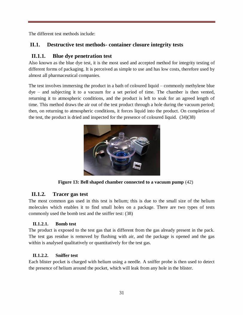
31
The different test methods include:
II.1. Destructive test methods- container closure integrity tests
II.1.1. Blue dye penetration test
Also known as the blue dye test, it is the most used and accepted method for integrity testing of
different forms of packaging. It is perceived as simple to use and has low costs, therefore used by
almost all pharmaceutical companies.
The test involves immersing the product in a bath of coloured liquid – commonly methylene blue
dye – and subjecting it to a vacuum for a set period of time. The chamber is then vented,
returning it to atmospheric conditions, and the product is left to soak for an agreed length of
time. This method draws the air out of the test product through a hole during the vacuum period;
then, on returning to atmospheric conditions, it forces liquid into the product. On completion of
the test, the product is dried and inspected for the presence of coloured liquid. (34)(38)
II.1.2. Tracer gas test
The most common gas used in this test is helium; this is due to the small size of the helium
molecules which enables it to find small holes on a package. There are two types of tests
commonly used the bomb test and the sniffer test: (38)
II.1.2.1. Bomb test
The product is exposed to the test gas that is different from the gas already present in the pack.
The test gas residue is removed by flushing with air, and the package is opened and the gas
within is analysed qualitatively or quantitatively for the test gas.
II.1.2.2. Sniffer test
Each blister pocket is charged with helium using a needle. A sniffer probe is then used to detect
the presence of helium around the pocket, which will leak from any hole in the blister.
Figure 13: Bell shaped chamber connected to a vacuum pump (42)
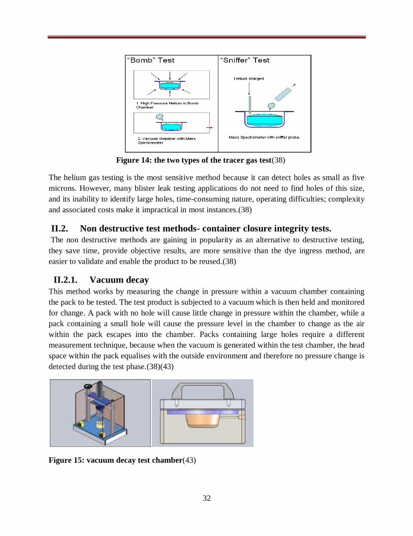
32
The helium gas testing is the most sensitive method because it can detect holes as small as five
microns. However, many blister leak testing applications do not need to find holes of this size,
and its inability to identify large holes, time-consuming nature, operating difficulties; complexity
and associated costs make it impractical in most instances.(38)
II.2. Non destructive test methods- container closure integrity tests.
The non destructive methods are gaining in popularity as an alternative to destructive testing,
they save time, provide objective results, are more sensitive than the dye ingress method, are
easier to validate and enable the product to be reused.(38)
II.2.1. Vacuum decay
This method works by measuring the change in pressure within a vacuum chamber containing
the pack to be tested. The test product is subjected to a vacuum which is then held and monitored
for change. A pack with no hole will cause little change in pressure within the chamber, while a
pack containing a small hole will cause the pressure level in the chamber to change as the air
within the pack escapes into the chamber. Packs containing large holes require a different
measurement technique, because when the vacuum is generated within the test chamber, the head
space within the pack equalises with the outside environment and therefore no pressure change is
detected during the test phase.(38)(43)
Figure 15: vacuum decay test chamber(43)
Figure 14: the two types of the tracer gas test(38)
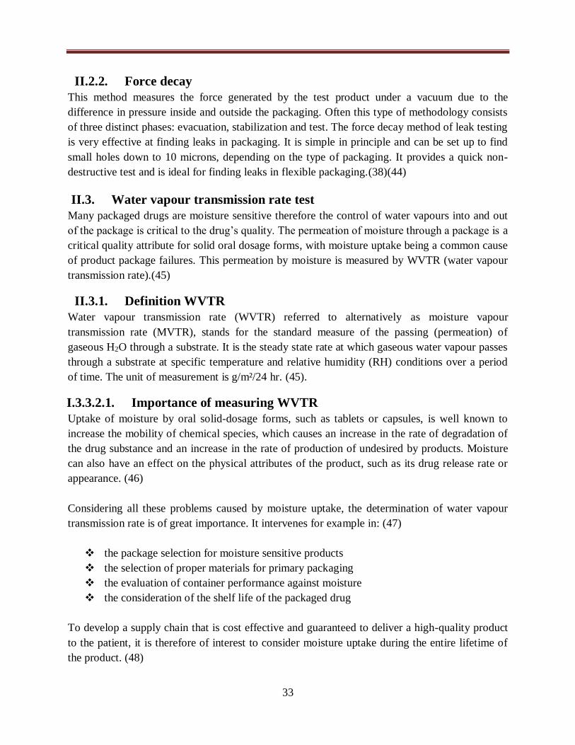
33
II.2.2. Force decay
This method measures the force generated by the test product under a vacuum due to the
difference in pressure inside and outside the packaging. Often this type of methodology consists
of three distinct phases: evacuation, stabilization and test. The force decay method of leak testing
is very effective at finding leaks in packaging. It is simple in principle and can be set up to find
small holes down to 10 microns, depending on the type of packaging. It provides a quick non-
destructive test and is ideal for finding leaks in flexible packaging.(38)(44)
II.3. Water vapour transmission rate test
Many packaged drugs are moisture sensitive therefore the control of water vapours into and out
of the package is critical to the drug’s quality. The permeation of moisture through a package is a
critical quality attribute for solid oral dosage forms, with moisture uptake being a common cause
of product package failures. This permeation by moisture is measured by WVTR (water vapour
transmission rate).(45)
II.3.1. Definition WVTR
Water vapour transmission rate (WVTR) referred to alternatively as moisture vapour
transmission rate (MVTR), stands for the standard measure of the passing (permeation) of
gaseous H2O through a substrate. It is the steady state rate at which gaseous water vapour passes
through a substrate at specific temperature and relative humidity (RH) conditions over a period
of time. The unit of measurement is g/m²/24 hr. (45).
I.3.3.2.1. Importance of measuring WVTR
Uptake of moisture by oral solid-dosage forms, such as tablets or capsules, is well known to
increase the mobility of chemical species, which causes an increase in the rate of degradation of
the drug substance and an increase in the rate of production of undesired by products. Moisture
can also have an effect on the physical attributes of the product, such as its drug release rate or
appearance. (46)
Considering all these problems caused by moisture uptake, the determination of water vapour
transmission rate is of great importance. It intervenes for example in: (47)
the package selection for moisture sensitive products
the selection of proper materials for primary packaging
the evaluation of container performance against moisture
the consideration of the shelf life of the packaged drug
To develop a supply chain that is cost effective and guaranteed to deliver a high-quality product
to the patient, it is therefore of interest to consider moisture uptake during the entire lifetime of
the product. (48)

34
II.3.3. Methods of measuring WVTR
The testing of water vapour permeability is widespread throughout the packaging and other
industries. There are a number of WVTR test methods that conform to recognized U.S and
international ASTM, ISO, and TAPPI standards(45).
The following are some of the methods used to test WVTR:
II.3.3.1. Gravimetric test method
This is the traditional method that has been used to measure WVTR, it also referred to as the cup
method. The Principe of this method involves placing a small sample of the test materials over
the top of a pre-made metal cup. The cup may contain water, in which case, the water vapour
would pass through the test material and the cup would lose weight over time. (49)
Depending on the application, gravimetric measurement is generally performed either using the
Absorption method (“dry cup”) or Desorption method (“wet cup”). In the Absorption method,
the cup is filled with a water-absorbing material (for example calcium chloride or molecular
sieve), and the relative humidity outside the cup is maintained at some high level. All water
vapour that permeates through the film is absorbed into the material in the cup, resulting in a net
weight gain of the cup system. The cup is weighed at regular intervals on a precision balance.
The Desorption method employs the same concept, except that the high humidity atmosphere is
located inside the receptacle (either as liquid water or as a salt solution, depending on the relative
humidity level desired). In this test, water vapour permeates through the film from the interior of
the cup, leading to a net weight loss over time.(50)
Dry cup method
Wet cup method
II.3.3.2. Automated WVTR testing methods
Many of the disadvantages of the gravimetric WVTR test method can be overcome using the
new automated test methods. (50)
Low relative humidity
(climate chamber)
Water or salt solution
High relative humidity
(climate chamber)
Absorbent material
Figure 16: the two types of gravimetric WVTR testing(50)

35
There are several types of automatic testers available:
II.3.3.2.1. Dynamic relative humidity measurement
A film sample is inserted into test chamber; the lower test chamber has a saturated atmosphere
maintained by a small water reservoir, while the upper chamber contains a sensitive, fast-
responding relative humidity sensor. The upper chamber is first dried to a defined humidity level
using dry air. When the drying is complete, the air-flow is stopped and the valves closed. From
that point, the chamber is a closed system, in which transmission of water vapour through the
sample causes an increase in relative humidity in the upper chamber. The instrument measures
the time required for the upper chamber humidity to increase from a pre-defined lower limit to a
pre-defined upper limit. The measured time interval is compared to the time obtained during
calibration with a standard film of known permeability, and the result is expressed as the water
vapour transmission rate in g/m2/24 hr. (50)
II.3.3.2.2. Electrolytic analysis
The testing principle of this method involves the separation of the gas transmission cell
integrated with the test specimen, into a controlled humidity chamber and a dry chamber. A
stream of dry carrier gas is then passed over the dry portion of the sample, and this carrier gas
transmits the water vapour pervading via the sample from the controlled humidity chamber into
an electrolytic cell.(51)
Lower chamber
saturated atmosphere
Upper chamber
Sensors and electronics
Figure 17:dynamic relative humidity tester(50)
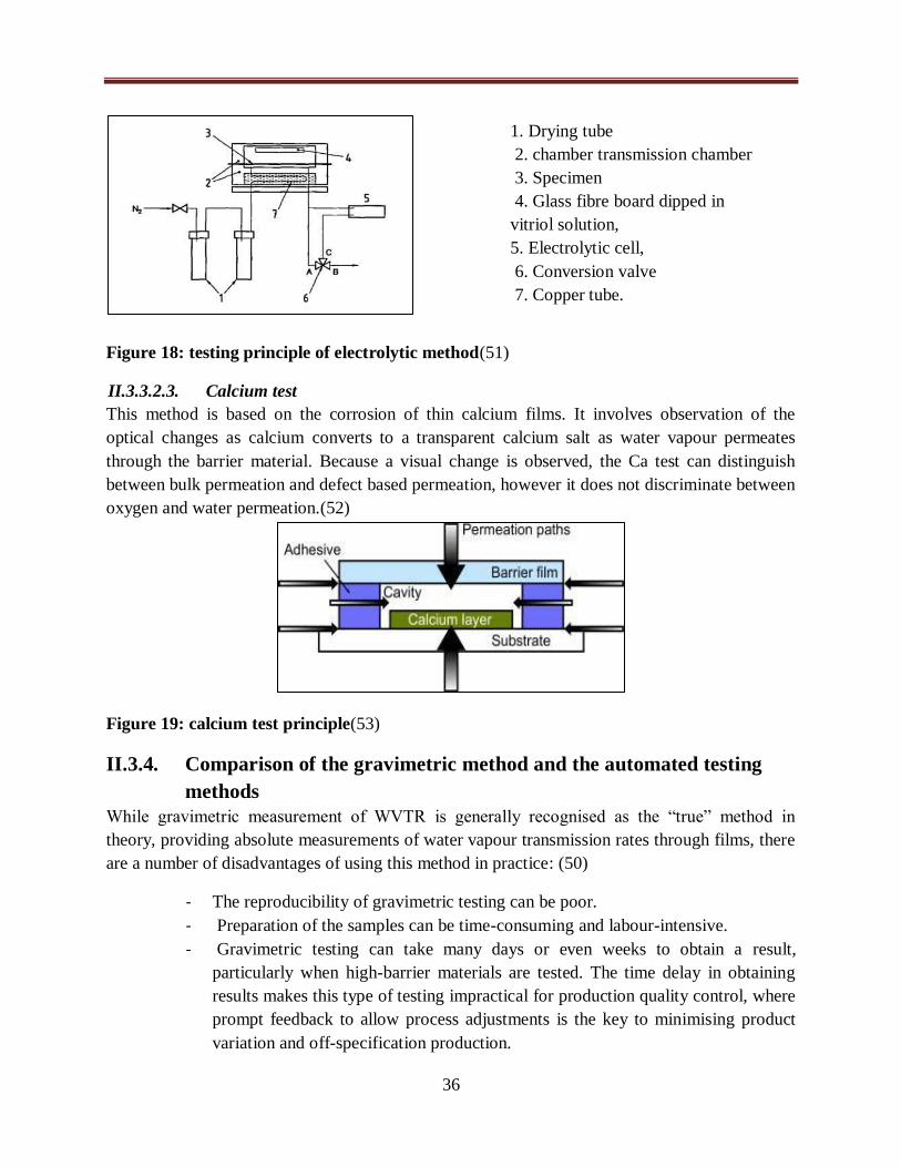
36
Figure 18: testing principle of electrolytic method(51)
II.3.3.2.3. Calcium test
This method is based on the corrosion of thin calcium films. It involves observation of the
optical changes as calcium converts to a transparent calcium salt as water vapour permeates
through the barrier material. Because a visual change is observed, the Ca test can distinguish
between bulk permeation and defect based permeation, however it does not discriminate between
oxygen and water permeation.(52)
Figure 19: calcium test principle(53)
II.3.4. Comparison of the gravimetric method and the automated testing
methods
While gravimetric measurement of WVTR is generally recognised as the “true” method in
theory, providing absolute measurements of water vapour transmission rates through films, there
are a number of disadvantages of using this method in practice: (50)
- The reproducibility of gravimetric testing can be poor.
- Preparation of the samples can be time-consuming and labour-intensive.
- Gravimetric testing can take many days or even weeks to obtain a result,
particularly when high-barrier materials are tested. The time delay in obtaining
results makes this type of testing impractical for production quality control, where
prompt feedback to allow process adjustments is the key to minimising product
variation and off-specification production.
1. Drying tube
2. chamber transmission chamber
3. Specimen
4. Glass fibre board dipped in
vitriol solution,
5. Electrolytic cell,
6. Conversion valve
7. Copper tube.

37
To over the shortcomings of the cup method, several companies tried to automate the water
vapour transmission rate testing. These test methods have the following advantages:(54)
- Provide quick and accurate results
- There is less human interaction
- Greater sensitivity, repeatability and precision.
- Reduction of labour costs
- Increase productivity

Practical
research

39
I. Introduction
In the pharmaceutical industry, considerable efforts are made to develop products that are stable
and have a long shelf life. Among the most important factors in the stability of the product is the
package design. Package designs starts with determination of the physical and chemical
properties of the product it will contain and its relevant protection.
In this study we are going to look at the packaging of Clavodex tablets and powder at
Continental pharm laboratories, in particular the problems caused by moisture permeation on the
packaged drug and determine if the packaging used is adequate to protect the product from
moisture vapour. With the aim of carrying out an efficient and effective study we established
procedures for the adjustments of the packaging machines used in the packaging of Clavodex
powder and tablets, and we went on to prepare the samples of blister packs and bottles so as to
send them to the testing company. We also took the time to verify the conditions in which the
samples were produced to make sure they conform to the good manufacturing practices.
I.1. Objectives of study
The principal objective is the package validation of Clavodex powder and tablets using the
WVTR method.
Secondary objectives:
- Preparation of procedures for the adjustments of machines
- Adjustments of the parameters of machine used in sealing
- Sample preparation according to WVTR
I.2. Type of study:
It’s an observational and experimental study.
I.3. Place where the study was conducted
The practical study was conducted at CONTINENTAL PHARM LABORATORIES in Oran
during a three months internship (8 January 2019 to 7 April 2019).
I.3.1. Presentation of Continental Pharm Laboratories (CLP)
Continental Pharm laboratory is an industry of fabrication and importation of pharmaceutical
products located in the zone industrial En Nedjma Oran.
Created in 1998, CLP was dedicated to importing and distributing pharmaceutical products
nationwide. After 5 years of its existence, it transformed into a manufacturing industry. Now it is
a company that manufactures and imports pharmaceutical products.
It is the first in the western region to specialise in the production of antibiotics (family of the
beta-lactamines) and particularly amoxicillin in three dosage forms:
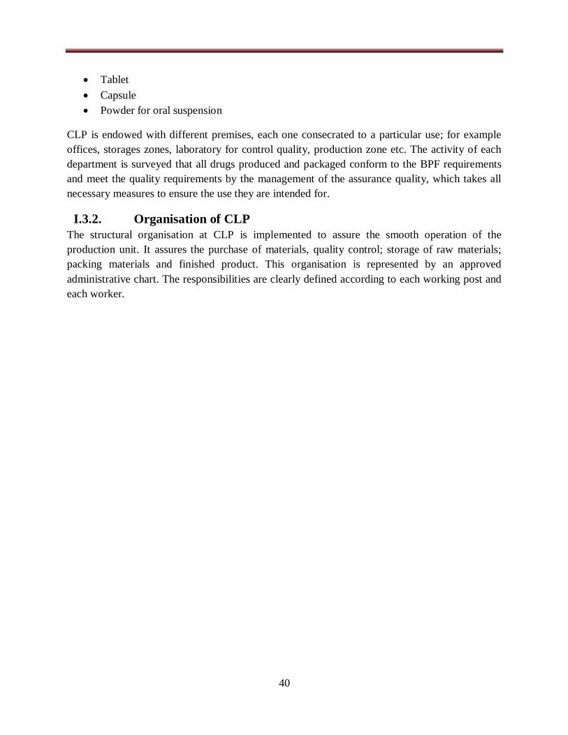
40
Tablet
Capsule
Powder for oral suspension
CLP is endowed with different premises, each one consecrated to a particular use; for example
offices, storages zones, laboratory for control quality, production zone etc. The activity of each
department is surveyed that all drugs produced and packaged conform to the BPF requirements
and meet the quality requirements by the management of the assurance quality, which takes all
necessary measures to ensure the use they are intended for.
I.3.2. Organisation of CLP
The structural organisation at CLP is implemented to assure the smooth operation of the
production unit. It assures the purchase of materials, quality control; storage of raw materials;
packing materials and finished product. This organisation is represented by an approved
administrative chart. The responsibilities are clearly defined according to each working post and
each worker.

41
Administrative chart
Figure 20: Administrative chart of CLP

42
I.4. Motivation of theme
The manufacturer’s main objective was to come up with guidelines in the manufacture of
Clavodex to help reduce the risk of degradation, during and after the manufacturing process. The
product Clavodex is composed of 2 active principal ingredients: clavulanic acid and amoxicillin.
Clavulanic acid being the most sensitive of the two; it is volatile and unstable when exposed to
high temperatures and it is hygroscopic. The degradation in quality of Clavodex is a visible
change in colour from white to yellow. Though this change in quality is visible, it is not harmful
to the user and neither does it alter the efficacy of the product.
There are many factors that contribute to the degradation in quality of the product and this
propelled CLP to investigate if it is moisture permeation into the package that causes this
degradation, as well as verifying if it is the type of packaging material used that allows
permeation or it is the quality of seals on the packages that allows permeation of moisture. It is
the purpose of this study to validate the packaging used in Clavodex and prove it is adequate to
protect the product using the WVTR method.
The manufacturer chose the WVTR method for the study because it is the most effective method.
II. Materials and equipment used
This is a brief outline of the primary packaging materials and the primary packaging equipments
we used in the preparation of packaging samples of Clavodex powder and Clavodex tablets at
CLP.
II.1. Materials used
The materials used in packaging are chosen in such a way to guarantee the quality, efficacy and
security of the product. Apart from the quality of sealing on the package, the permeability of the
material also plays a huge role in protecting the product from water vapour. In the packaging of
Clavodex it is very important to consider the impermeability of the material to water vapour.
In this study we used the following materials to prepare samples:
- Glass containers
- Plastic caps
Figure 21: glass container

43
- Foil-foil blister packs
- Syringe
- Distilled water
- Cotton
II.1.1. Types of materials used in primary packaging at CLP
Primary packaging materials used in the packaging of Clavodex powder and tablets at CLP
include:
II.1.1.1. Glass containers
The glass containers are used in packaging Clavodex powder for oral suspension. The glass used
for container is USP type III. It is untreated soda lime glass suitable for powders. The container
is closed by a screw cap with a polyethylene gasket fitted with a temper evident ring.
II.1.1.2. Blister pack
At CLP there are 2 types of blister packs used in packaging. One type consists of a cavity
constructed from clear, thermoformed plastic and the lid is foil; this type is used in the packaging
of Amodex tablets. The second type has both the cavities and the lid made of foil; it is used in
packaging Clavodex tablets.
The blister pack used in the packaging of Clavodex tablets is a foil/foil lamination used for
products that are susceptible to moisture or light. Clavodex is a product that requires the highest
form of protection from moisture and therefore it is packed in an alu/alu package.
Figure 22: plastic cap
Figure 23: front and back view of blister packs

44
Characteristics of the forming film
The forming film of the blister pack comprises a lamination of plastic film, adhesive, foil,
adhesive and an outer plastic film. The outer film which can be PET or PVC supports the thin
aluminium layer and acts as the heat-seal layer.
The foil-foil blisters cannot be made as form fitting like the plastic ones because of the
brittleness of the cold formed aluminium. The foil is shaped and moulded around a plug to form
a cavity. The cavities made in the cold forming process are larger and allow the product to move
inside the blister.(56)
At CLP the forming film used for Clavodex tablets is a cold form foil (alu/alu), it has the
advantage of having a near absolute barrier for moisture.
Characteristics of the lidding material
It is an aluminium foil printed on one side and heat sticking on the other side. The lidding
material is selected according to size, shape and weight of the product and the style of the
package. The surface of the lidding material is compatible with the heat seal coating processes.
The lidding material must also guarantee a WVTR that is as low as that of the forming films.(56)
The lidding material used at CLP is an aluminium foil printed on one side and heat sticking on
the other side. It is a push through foil.
I.1.2. Quality control of raw materials
The quality of materials used is controlled by the laboratory of control quality at CLP. Each
packing material that is bought has a control report which describes the article and the results of
the control. The supplier of the materials also provides a certificate of analysis for each article
which gives the physical and chemical tests done on the materials and the description and
specifications as well as the observations for every test performed. These documents are then
compiled and archived at the quality assurance office.
After the analysis of the raw materials, the conforming results obtained by the control quality
allow their usage.
II.2. Equipment used
The design and layout of equipment has a great impact on the efficiency of the packaging line.
The layout of the equipment should guarantee an easy access for the operators and the engineers
to access this equipment when adjustments and or maintenance are required. The layout of
equipment at CLP meets these requirements.
The equipment we used in this study is the primary packaging equipment used in the packaging
of Clavodex tablets and powder at CLP.
We used in this practical:
- Automatic blister machine (thermo former) - NMX

45
- Bottler filling and capping machine- RAV 05
- Bell shaped vacuum with pump
II.2.1. Automatic blister machine (thermo former) - NMX
The blister machine used in this line is an nMX with an alternative movement. It is used in the
packaging of Clavodex tablets.
II.2.1.1. Composition of the machine
1. Feeder of the forming film
2. PC vision system
3. Thermo forming post
4. PLC ( programme logic computer)
5. Feeder of products
6. Zone of insertion of products
7. Commanding screen and keyboard
8. Feeder of covering film
9. Sealing post
10. Blister cutter
11. Eliminator of empty blisters
12. Eliminator of incomplete blisters
II.2.1.2. Integrated controls of the machine in production:
- Control of presence of product by the vision system: SEA VISION
During packaging the PC vision system controls automatically and constantly the presence and
physical integrity of the product to locate the blisters that are to be eliminated and provoke the
corresponding reject signals.
Figure 24: NMX blister packing machine

46
- Control of product outside of the blister cavity S43
It has the function of detecting products, fragments of the product, or other foreign particles
present on the formed band or incorrectly placed in the cavity. This type of control is carried out
by passing a mobile blade on the forming material.
- Control of presence of forming material B40
It stops the machine in phase when the bobbin of forming material is finished and displays a
message of alarm.
- Control of minimum level of forming material B1
It warns the operator on the imminent change of the bobbin of forming material by a sound and
light signal, as well as an alarm message displayed on the screen.
- Control of junctions on the forming material B6
It detects the presence of a heat sticking adhesive band that is used for the joining of the two
ends of the bobbins. The photoelectric cell transmits the information to the automatic, which then
commands the rejection of blisters and stops the loader. The adjustment of the sensibility of the
cell is carried out by a button.
- Control of presence of lidding material S30
It stops the machine in phase when the bobbin is finished and an alarm message is displayed on
the screen.
- Control of the minimum level of lidding material B3
It warns the operator on the need to change the bobbin by sound and light signal as well as a
visual displayed message.
- Control of the junction on the lidding material B7
It detects the presence of a heat sticking adhesive band used for the joining of the two ends of the
bobbins. The photoelectric cell transmits the information to the automatic, which then commands
the rejection of blisters and stops the loader. Roughly speaking the adjustment of the sensibility
of the cell is carried out at once by the button.
- Control of the pace of the holder at the post sealing exit
This feature detects the correct position of the formed material (this material must advance a step
at each cycle of the machine), as well as the presence of possible objects between the inferior and
superior sealing plates using the intermediate of four sensors (S33, S33A, S33B, S33C). Each
Figure 25: Image of the control SEA vision on blister machine

47
time that one of the sensors turns off, the machine stops in phase, the sealing post immediately
opens and an alarm message is displayed on the screen.
- Control of the number of steps between the presence control of the product and the
ejection of blisters S68
It verifies that the number of steps between the axis of the feature which controls the presence of
the product and the axis of the cutting post corresponds to the one defined by the format during
production. It is composed of a wheel mounted on a sliding trolley detecting the maximum and
minimum limit created by the heat sticking band at the entrance of the cutting post. The thermo
former stops in phase and displays a warning message each time that the excursion of the wheel
goes beyond the defined limits.
- System of ejection of empty and incomplete blisters
It has the function of diverting blisters that do not conform, detected by the feature which
controls the presence of the product in the conveyor. It is made up of:
A photoelectric cell which detects the passage and authorises the rejection, it is
positioned on an adjustable support. Roughly the adjustment of the sensibility of
the cell determines the separating space between two blisters
A feature which ejects a gush of air and a deviation feature, which activates by
rejecting empty or incomplete blisters.
II.2.1.3. Operation of the blister machine
The machine is divided into 4 units according to operations done:
A. Forming station: there are two operations done at this level :
- Unwinding of the forming film:
A series of rollers unroll and regularly supply the thermoforming station with the forming film.
At each cycle a moving clamp moves the forming film forward.
- Forming of cavities: it involves 3 steps:
Heating - at the preheating station the forming film is heated by 2 plates, one above and the other
below to make the film malleable and make the thermoforming easy. This heating process is only
used when the forming film is PVC. When the forming film is aluminium the blister cavities are
cold pressed into shape at the forming unit.
Forming – this part has 2 matrices, one above and one below, the matrice above is brought close
to the film and exerts a pressure which allows the formation of the cavities.
Cooling – at the forming station the plate which is below is cooled down by a cycle of cold water
which makes the cavities rigid but avoids dilatation.
B. Feeding station
48
The loading area fills the blister cavities with the product.
C. Sealing unit:
- Supply of the lidding material - a series of rollers drives the bobbin of aluminium film up to
the sealing station.
- Blister sealing and printing – when the two films are superposed, they pass on to the sealing
plates; the upper plate is grooved and heated to an optimum temperature by electrical
resistances. The upper and lower plates come together and exert a certain pressure on the
two films to assure the sealing, the sealing occurs only on specified zones. At the same time
the pistons inside the plates with the help of the heat from the plates will print the necessary
information correctly. After sealing the blisters then move on to the cooling station.
D. Cutting unit:
Once at the cutting zone the last row of the band of blisters is placed under the guillotine. Using
2 blades, one inferior and the other superior the blisters are cut out and brought out towards the
secondary packaging station.
The blisters which are empty and faulty are eliminated at different points.
II.2.1.4. Flowchart diagram of packaging on blister machine
We established a flowchart diagram for the primary packaging of Clavodex tablets in blister
packs. The general sequence involves cold formation of the blister cavities on the ALU foil,
loading the blisters with the tablets, placing the lidding material over the blister and heat sealing
the package. The expiry date and batch number are then printed on the blisters before they are
cut. The blisters are then ejected; the blisters that conform proceed to secondary packaging via
the conveyor belt, while the blisters that have defects drop into the waste system.

49
Blister packaging line:
Formation of cavities
Sealing of blisters with the lidding film
Sea vision control system
Blister cavities filled with tablets
Supply of lidding film: aluminium
Printing of expiry date and batch number on the blister pack
Blisters packs cut off
Waste system Secondary packaging
Blisters with defects Blisters without defects
Figure 26: Flowchart diagram of primary packaging on the blister machine

50
II.2.2. Powder filling and capping machine- RAV 05
The machine used in this line is an automatic RAV 05 which is an entirely autonomous machine
unit for the automatic filling of powders or fine granules in bottles. The filling operation as well
as the closure of the bottle operation is performed during the machine automatic cycle.
II.2.2.1. Composition of the machine:
1. Conveyor belt
2. The carters
3. The carousel
4. Bottle lifter
5. Dosing /filling head
6. Capping head
7. Closing / tightening head
8. Vibrating bowl
9. CFM pump
II.2.2.2. Integrated controls of the machine during production
- Sensor for the presence of bottle:
The first sensor is placed below the carousel and just before the bottle lifter sets to command the
filling of the bottle; it also commands the insertion and screwing of the cap by means of 2 other
sensors.
- Sensors on the conveyor belt:
There are 2 sensors on the conveyor belt, one before the carousel and another which is after. The
first one is for the commanding the minimum level of bottles and the second one is for
commanding the maximum level of bottles.
- Sensor of presence of cap:
It is placed before the cap inserter; it detects the presence of the cap and provokes an immediate
stop of the machine if the cap is absent.
Figure 27: RAV 05 bottle filling and capping machine

51
II.2.2.3. Operation of the machine
- Filling of the bottles: The bottles are received by the conveyor belt from the blower, and
transported towards the carousel. The carousel is a round with 16 spaces which fixes and
transports the bottles towards the filling head, capping head and lastly the tightening head.
The bottle lifter lifts up the bottle to the spout of the filling head for filling, and brings it
down again after filling is complete. The filler has a predetermined dose it is programmed to
put in the bottle.
- Capping and closing: The capping head is attached to a vibrating bowl which feeds the
machine with caps. The capping head allows the capping of the bottle by means of a piston.
After the bottle is capped the tightening head tightens the cap by a strong rotating
movement, allowing an air tight sealing of the bottle. The distance between the tightening
head and the cap is adjusted by a manual steering wheel placed above the tightening head.
A. Related equipments of the RAV 05
These include the vibrating bowl and the CFM pump.
The vibrating bowl is a dispositive for the distribution of caps; it feeds the machine by the
intermediate of a conveyor canal under vibration.
The CFM pump is composed of a control cabinet, security filter,
B. Frame of the RAV 05
It includes the technical parts of the machine:
- Electric motor
- Electrical cabinet
- Peripheral connections: electrical, aspiration, manometer of compressed air
II.2.2.4. Flowchart diagram of powder filling and capping machine
The general sequence of the packaging of powder in bottles involves; the introduction of the
bottles on round table and then passage of each bottle to the blower one by one before passing on
to the conveyor belt. The conveyor belt then drives the bottles to the dosing head, the bottle is
lifted up to the dosing head and brought down after filling. The dosing head fills each bottle with
a predetermined dose of the powder. The bottle is capped and the cap is tightened by the
tightening head before passing on to the conveyor belt which leads the bottles to the labelling
machine and secondary packaging. Unlike the blister machine that automatically detects the
blisters with defect, the bottles that do not conform have to be picked out manually by the
operators.

52
Bottle packaging line:
Supply of bottles on the round table
Passage of each bottle by the blower
Positioning of bottles on the carousel
Sensor for commanding the minimum level of bottles
Lifting of bottle to the spout of
dosing/filling head and
Bottle is filled with a predetermined dose of powder
Replacing the bottle on the carousel
Capping head places the cap on the bottle
Tightening of the cap on the bottle
Sensor on piston of capping head that detects presence of the bottle
Sensor that commands the maximum amount of bottles
Labelling of bottle
Manual removal of defective bottles by the operator
Figure 28: flowchart diagram of packaging on the powder filling and capping machine

53
II.2.3. Bell shaped vacuum with pump
This piece of equipment is used for the in process control of packaged containers and blisters. As
the name suggests, it is a bell shaped chamber with a lid and it is connected to a pump. It is used
to detecting any leaks on the packaged product during the methylene blue dye penetration test.
III. Method
Before preparing the samples required for the WVTR test, the assurance quality service of
Continental pharm prepared procedures to assure the best operation of the packaging machines
and to help in the necessary adjustments. They also went ahead and prepared a procedure for the
preparation of samples.
III.1. Establishing procedures
The assurance quality service had to establish procedure to assure the samples were prepared
correctly and according to the good manufacturing practices. The procedure prepared included:
- Procedure for the adjustment of RAV 05, the powder filling and capping machine
- Procedure for the adjustment of NMX, the blister machine
- Sampling procedure
- Procedure of preparation of samples according to the WVTR method
III.2. Execution of the adjustments of the packaging machines
The execution included doing the following:
- Verifying that the operating procedures of the two packaging machines are respected
- Verification of the operating conditions
- Verification of the control systems
- Verifying the preliminaries and assembling; before the start of each operation the operator
must carry out some preliminary operations.
- Carrying out empty tests; the empty test allows verifying that the machine is working well,
verifying the cutting of blisters, printing, formation, sealing as well as the correct positioning
of the bobbins.
- When operating on the batch it is necessary to do an integrity test and a visual control of the
manufactured product.
Figure 29: bell shaped vacuum with pump
54
- Carrying out adjustments if necessary; during the packaging operation, the operator is
entitled to do certain adjustments; for example the speed of the machine.
III.3. Preparation of samples
In this study we prepared samples of 10 blister packs used in the packaging of Clavodex tablets
and 10 glass bottles with plastic caps used in the packaging of Clavodex powder. Instead of the
product, we placed cotton soaked with a bit of water inside each blister pack and each bottle.
This testing method involves the evaluation of the loss in weight of package (bottle, blister pack
or sachet) containing water and placed in a chamber with a circulating gas which detects water
vapour escaping the package. The aim is to conclude on the quality of sealing and the air
tightness of the package.
III.3.1. Preparing samples of sealed bottles
Before the samples could be prepared, we had to define and determine the parameters of
tightness of cap on the container as well as the air tightness of container. The machine was
adjusted a number of times before reaching the optimal conditions of tightness and air tightness
of the container.
III.3.1.1. Preparing samples of bottles according to the WVTR method
The procedure for the preparation of samples was established by the company concerned with
testing the samples. (See annexe 1)
- The bottles and closures were prepared as they would be used in production. To label the
each bottle a marker pen was used.
- A piece of cotton wool was placed into the bottle, to loosely occupy approximately 1/4 of
the volume of the bottle.
- Then 1/10 of the volume of the container was filled with distilled water. The amount of
water was not critical, as it was there only to create a humid environment for the test.
- Before proceeding to the capping of the bottles we made sure that the threads of the bottle
were dry.
- After the bottles were sealed, they were packed upright and separated to avoid breaking
them and then send for testing.
III.3.2. Preparing samples of blister packs
The sealing temperature was set at different temperatures and observed for blister quality. Based
on the result optimum sealing temperature range was established. The sealing pressure was fixed
at 6 bars.
III.3.2.1. Preparing of samples of blister packs according to the WVTR method
The protocol for the preparation of samples of blister packs was established by the quality
assurance service (internal protocol).
- The aluminium forming film used for making the blister packs was loaded on the
machine and the cavities formed the same way as in normal production.

55
- A small piece of cotton was placed inside each cavity before adding a few drops of
distilled water with a syringe.
- The blister cavities were covered and sealed using the lidding material on the machine.
- Each blister pack was marked using a marker pen and packed with the appropriate
documents, before sending for testing.
56
IV. Results
IV.1. Procedure of adjustment of RAV 05 - powder filling and capping
machine
Summary:
I / Objective
II / Area of application
III /Responsibilities
IV/ Associated references and document
IV-1/References
IV-2/ Associated documents
V / Abbreviations and definitions
VI /Contents
VI-1/ Technical characteristics of the RAV 05
VI-2/ Procedure of adjustment of the RAV05
VI-3/ Sampling procedure
VI-4/ Controls
VII/ Registration
VIII/Annexes
57
I / Objective:
The objective of this procedure is to define and determine the parameters of control of the
tightness of caps on the bottles dedicated for the packaging of Clavodex powder for oral solution,
as well as their air tightness. After many adjustments, the main concern is to come up with
optimal conditions of tightness and air tightness of the bottles.
II / Area of application
The present procedure is applicable to the machine RAV 05 on the bottles dedicated to the
finished product for solution oral.
III /Responsibilities
The following are responsible for the execution of this procedure:
- The production operators on the RAV, production department,
- Maintenance staff ; maintenance department,
- The production operators and analysts in terms of control of integrity,
IV/ Associated references and document
IV-1/ References
- Manuel of the machine RAV,
- Procedure on how to use the RAV,
- Good Manufacturing Practices,
IV-2/ Associated DOCUMENTS
- Register of measurements of torque meter ,
- Register of the tests of integrity,
- Report of registered torque-meter tests and integrity tests ,
V / Abbreviations and definitions
NA
VI /Contents
VI-1/ Technical Characteristics of the RAV:
VI-2/ Procedure of adjustment of the RAV 05
This machine has a number of adjustments that have to be performed on it; some adjustments are
done by the maintenance team and some by the operators when the machine is in operation.

58
The adjustments done by maintenance include varying the height of the tightening head to three
levels, as well as the tightening torque to nine positions. The operators have to vary the speed of the
tightening head up to ten different speeds, as well as the height of the tightening head, while the
height of the tightening head is fixed at one value at a time
The adjustments are illustrated in Table 3 below: one level of the height of the tightening head is
considered.
Table III: Adjustments performed on the powder filling and capping machine
Speed of tightening head
1 2 3 4 5 6 7 8 9 10
Posi
tion
s of
the
tigh
ten
ing t
orq
ue
1
2
3
4
5
6
7
8
9
These adjustments are then optimised to:
- Three levels for the height of the tightening head
- Three positions for the tightening torque
- Four speeds for the tightening head
Table 3 shows the optimised adjustments by the columns and rows coloured in grey. Table 3 is
then modified to form Table IV
Table IV: Optimised adjustments of the powder filling and capping machine
Speed of tightening head
H1 4 5 6 7
Po
siti
on
s of
the
tigh
ten
ing
torq
ue
4
5
6

59
VI-3/ Sampling procedure
The sampling procedure is done according to the number of optimised adjusted parameters.
The identification of samples is done by crossing the adjustments of the speed of the tightening
head and the position of the tightening torque for a fixed height H1
Table V below shows the number of adjustments when the height of the tightening head is fixed
at one position.
Table V: The number of adjustments when the tightening head is fixed at one position
Speed of the tightening head
H1 1 2 3 4
Posi
tion
s of
the
tigh
ten
ing
torq
ue
1 1.1 1.2 1.3 1.4
2 2.1 2.2 2.3 2.4
3 3.1 3.2 3.3 3.4
VI-3-1/ Preparing samples of bottles according to the WVTR method
The bottles and closures were prepared as they would be used in production. To label the each
bottle a marker pen was used.
- A piece of cotton wool was placed into the bottle, to loosely occupy approximately 1/4 of
the volume of the bottle.
- Then 1/10 of the volume of the container was filled with distilled water. The amount of
water was not critical, as it was there only to create a humid environment for the test.
- Before proceeding to the capping of the bottles we made sure that the threads of the bottle
were dry.
- After the bottles were sealed, they were packed upright and separated to avoid breaking
them and then send for testing.
VI-4/ Controls carried out
After the determination of the number of adjustments to carry out on the RAV 05, the samples
are numbered up to 10 by the adjustments.
For each adjustment there is a corresponding measure of torque meter as well as an integrity test.
To gather all the measurements which are taken, a register are established which records the
identity of samples and the results.
Table VI: Record of torque-metre measurements and integrity tests
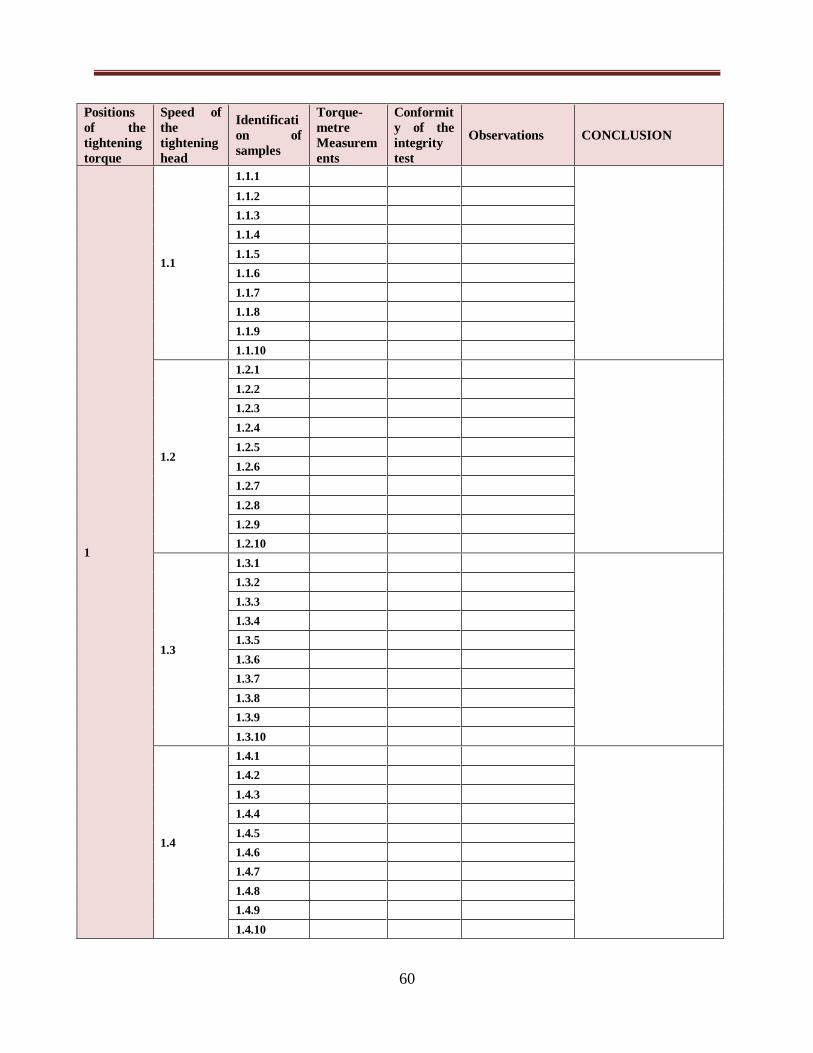
60
Positions
of the
tightening
torque
Speed of
the
tightening
head
Identificati
on of
samples
Torque-
metre
Measurem
ents
Conformit
y of the
integrity
test
Observations CONCLUSION
1
1.1
1.1.1
1.1.2
1.1.3
1.1.4
1.1.5
1.1.6
1.1.7
1.1.8
1.1.9
1.1.10
1.2
1.2.1
1.2.2
1.2.3
1.2.4
1.2.5
1.2.6
1.2.7
1.2.8
1.2.9
1.2.10
1.3
1.3.1
1.3.2
1.3.3
1.3.4
1.3.5
1.3.6
1.3.7
1.3.8
1.3.9
1.3.10
1.4
1.4.1
1.4.2
1.4.3
1.4.4
1.4.5
1.4.6
1.4.7
1.4.8
1.4.9
1.4.10

61
Position of
the
tightening
torque
Speed of
the
tightening
head
Identificati
on of
samples
Torque-
metre
Measurem
ents
Conformit
y of the
integrity
Test
Observations CONCLUSION
2
2.1
2.1.1
2.1.2
2.1.3
2.1.4
2.1.5
2.1.6
2.1.7
2.1.8
2.1.9
2.1.10
2.2
2.2.1
2.2.2
2.2.3
2.2.4
2.2.5
2.2.6
2.2.7
2.2.8
2.2.9
2.2.10
2.3
2.3.1
2.3.2
2.3.3
2.3.4
2.3.5
2.3.6
2.3.7
2.3.8
2.3.9
2.3.10
2.4
2.4.1
2.4.2
2.4.3
2.4.4
2.4.5
2.4.6
2.4.7
2.4.8
2.4.9
2.4.10

62
Positions
of
tightening
torque
Speed of
tightening
head
Identificati
on of
samples
Torque-
meter
Measurem
ents
Conformit
y of the
integrity
Test
Observations CONCLUSION
3 3.1 3.1.1
3.1.2
3.1.3
3.1.4
3.1.5
3.1.6
3.1.7
3.1.8
3.1.9
3.1.10
3.2 3.2.1
3.2.2
3.2.3
3.2.4
3.2.5
3.2.6
3.2.7
3.2.8
3.2.9
3.2.10
3.3 3.3.1
3.3.2
3.3.3
3.3.4
3.3.5
3.3.6
3.3.7
3.3.8
3.3.9
3.3.10
3.4 3.4.1
3.4.2
3.4.3
3.4.4
3.4.5
3.4.6
3.4.7
3.4.8
3.4.9
3.4.10

63
VII/ Register
A copy of this current procedure is kept at the production site and the original document is kept at
the assurance quality office; it is valid for three years.
VIII/ANNEXES

64
IV.2. Procedure of adjustment of the NMX- blister machine
Summary:
I / Objective
II / Area of application
III /Responsibilities
IV/ Associated references and document
IV-1/References
IV-2/ Associated documents
V / Abbreviations and definitions
VI /Contents
VI-1/ Technical characteristics of the NMX
VI-2/ Procedure of adjustment of the NMX
VI-3/ preparing blister pack samples according to the WVTR method
VI-4/ Controls
VII/ Registration
VIII/Annexes

65
I / Objective:
The objective of this procedure is to define and determine integrity of the seal on the blister
packs dedicated for the packaging of Clavodex tablets. After many adjustments, the main
concern is to come up with the optimal conditions of sealing temperature and pressure.
II / Area of application
The present procedure is applicable to the machine NMX, for the packaging of Clavodex tablets.
III /Responsibilities
The following are responsible for the execution of this procedure:
- The production operators on the NMX, production department,
- Maintenance staff ; maintenance department,
- The production operators and analysts in terms of control of integrity,
IV/ Associated references and document
IV-1/ References
- Manuel of the machine NMX,
- Procedure on how to use the NMX,
- Good Manufacturing Practices,
IV-2/ Associated DOCUMENTS
- Register of the tests of integrity,
- Report of registered integrity tests ,
V / Abbreviations and definitions
NA
VI /Contents
VI-1/ Technical Characteristics of the NMX:
VI-2/ Procedure of adjustment of the NMX
Some adjustments are done by the maintenance team and some by the operators when the
machine is in operation.

66
The adjustments done by maintenance include changing the format of moulding plug according to
the size of cavities required, inserting the bobbins of ALU forming foil and the lidding foil, as well
as checking that the machine is working well and making adjustments where necessary.
The operators have to adjust the speed of the machine, the intensity of vibration of the feeding bowl
and the speed of the levelling roller. They also have to verify the pressure of air and water, that
there are no leaks and that the sealing temperature has been reached.
VI-3/ Preparing of blister pack samples according to the WVTR method
The protocol for the preparation of samples of blister packs was established by the assurance
quality service (internal protocol).
- The aluminium forming film used for making the blister packs was loaded on the
machine and the cavities formed the same way as in normal production.
- A small piece of cotton was placed inside each cavity before adding a few drops of
distilled water with a syringe.
- The blister cavities were covered and sealed using the lidding material on the machine.
- Each blister pack was marked using a marker pen and packed with the appropriate
documents, before sending for testing.
VI-4/ Controls carried out
N/A
VI-5/ Annexe

67
IV.4.3. Procedure of the method WVTR
Summary:
I / Objective
II / Area of application
III /Responsibilities
IV/ Associated references and document
IV-1/References
IV-2/ Associated documents
V / Abbreviations and definitions
VI /Contents
VI-1/ preparing blister pack samples according to the WVTR method
VI-2/ preparing sealed bottle samples according to the WVTR method
VII/ Registration
VIII/Annexes

68
I / Objective:
The present procedure has objective of defining and describing the method WVTR and the
parameters which can influence the determination of WVTR sealed bottles and blisters.
II / Area of application
The present procedure is applicable to the packaging of Clavodex tablets in blisters and
Clavodex powder for oral solution in a bottle.
III /Responsibilities
The following are responsible for the execution of this procedure:
- The production operators on the nMX and RAV 05, production department,
- Maintenance staff ; maintenance department,
- The production operators and analysts in terms of control of integrity,
- The laboratory of quality control
IV/ Associated references and document
IV.1/ Reference:
- USP
IV.2/ Associated Documents:
- Versapem procedure for WVTR testing for sealed containers
- Procedure of use of the powder filling and capping machine- RAV05
- Procedure of the adjustments of the powder filling and capping machine RAV05
- Procedure of use of the blister machine - NMX
- Procedure of adjustments of the blister machine -NMX
V / Abbreviations and definitions
1. Definition
Water vapour transmission rate – is the measurement of passage of water
vapour through a substance.
2. Abbreviation
WVTR: water vapour transmission rate
USP : united states pharmacopeia
CIaire : conditionnement primaire

69
VI /Contents
VI.1/ General description of the method
It involves the determination of passage of water vapour across a package (bottle, blister....)
introduced in an enclosure that has a gas circulation that detects the leakage of water vapour, the
aim is to conclude on the quality of the seal and the integrity of the package.
VI.2/ Application of the method on glass bottle
Variation of Moisture permeability of glass bottles when the speed of the tightening head and
the position of the tightening torque is increased.
VI.2.1/ The Adjustments of the powder filling and capping machine.
See –procedure of the adjustments of the powder filling and capping machine.
VI.2.2/ Determination of WVTR
- Place the bottles in an enclosure with gas circulation which detects the moisture vapour
that comes from the bottles.
VI.3/ Application of the method on blisters
VI.3.1/ The adjustments of the blister machine NMX
See the procedure for adjustments of the blister machine NMX.
VI.3.2/ Determination of WVTR
Place blisters in an enclosure with gas circulation, it is this gas that detects the quantity of water
vapour that escapes and quantifies it by various method according to the type of tester used.
VII/ Registration
VIII/Annexes

70
IV.4. Verification of conditions during the sample preparation process
IV.4.1. Normal values of temperature and humidity in the room
The values of temperature and humidity of the packaging room must be verified constantly. If
there are any slight changes in these two parameters, production has to be stopped and measures
taken to have the normal temperature and pressure of the room. The temperature and pressure are
monitored by a Hygro-thermometer on the wall of the room and the values are noted down at
intervals on a paper kept next to it.
Table below presents the normal values of temperature and pressure of the room:
Table VII: Normal room temperature and pressure
Parameter Normal value
Temperature 20°C ≤ T≤ 24°C
Humidity ≤20%
IV.4.2. Results of adjustment of the blister machine NMX
To make sure that the samples were prepared in the right way, the parameters of the blister
machine had to be controlled and the packaged samples produced also had to be controlled.
IV.4.2.1. Control of parameters of blister machine
The operators had to verify that the temperature of the sealing plate, sealing pressure and the
moulding plate of the machine conform to those specified in the documents.
Table VIII: Results of the control of blister machine
Verification Specification Result
Temperature of sealing plate 170 -180 °C 170°C
Sealing pressure 6 bar 6 bar
N° of matrix used 3045-2 Verified
IV.4.2.2. Control of blister samples produced
The first blisters produced are verified to make sure they are properly sealed, the cavities are
well formed and that they are no folds on the aluminium, the operators then had to test the
integrity of the blister pack seals using the dye penetration test with the bell shaped chamber.
Integrity test

71
- A sample of six blisters was taken by the operators to in process control laboratory.
- The blisters were immersed in the bell shaped chamber filled with a solution of 2%
methylene blue and cold water. The pressure was reduced to -0.50 bar for two minutes.
- After two minutes the blisters were taken out and washed with running water.
- They were then dried using an absorbent paper and visually examined by the naked eye
to verify the absence of penetration of the methylene blue solution into the blister.
- The operator then opens each blister to verifying the absence of penetration of the dye
solution inside.
Table IX: Results from control of blister samples
Test applied Specification Result
Integrity and absence of folds
on aluminium
Conform Conform
Well formed cavities Conform Conform
Integrity of seal Conform Conform
Dye penetration test Conform Conform
IV.4.3. Results of the adjustment of the powder filling and capping
machine
To make sure that the samples were prepared in the right way, the parameters of the powder
filling and capping machine had to be controlled and the packaged samples produced also had to
be controlled.
IV.4.3.1. Control of parameters of machine
On this machine the operators had to control the speed of the tightening head to assure that the
bottles were not closed too tight or too loose. The speed of the tightening head used depended on
the type of plastic cap used.
Table X: Results of the control of powder filling and capping machine
Verification Specification Result
Speed of rotating head
Cap type 2 Cap type 3
Conform 5 6-7
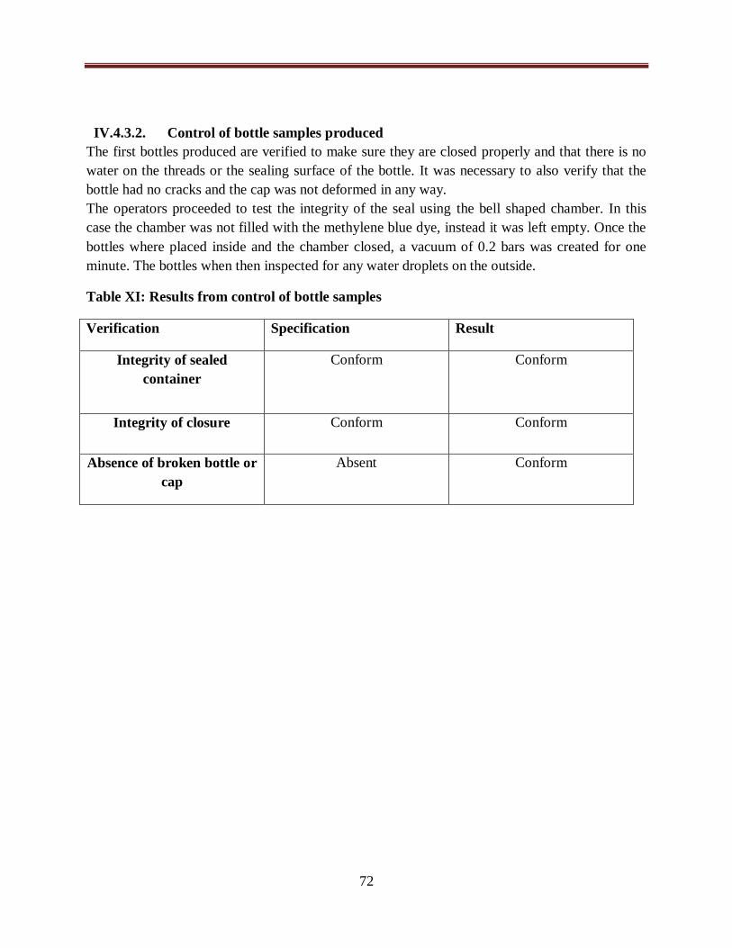
72
IV.4.3.2. Control of bottle samples produced
The first bottles produced are verified to make sure they are closed properly and that there is no
water on the threads or the sealing surface of the bottle. It was necessary to also verify that the
bottle had no cracks and the cap was not deformed in any way.
The operators proceeded to test the integrity of the seal using the bell shaped chamber. In this
case the chamber was not filled with the methylene blue dye, instead it was left empty. Once the
bottles where placed inside and the chamber closed, a vacuum of 0.2 bars was created for one
minute. The bottles when then inspected for any water droplets on the outside.
Table XI: Results from control of bottle samples
Verification Specification Result
Integrity of sealed
container
Conform Conform
Integrity of closure Conform Conform
Absence of broken bottle or
cap
Absent Conform
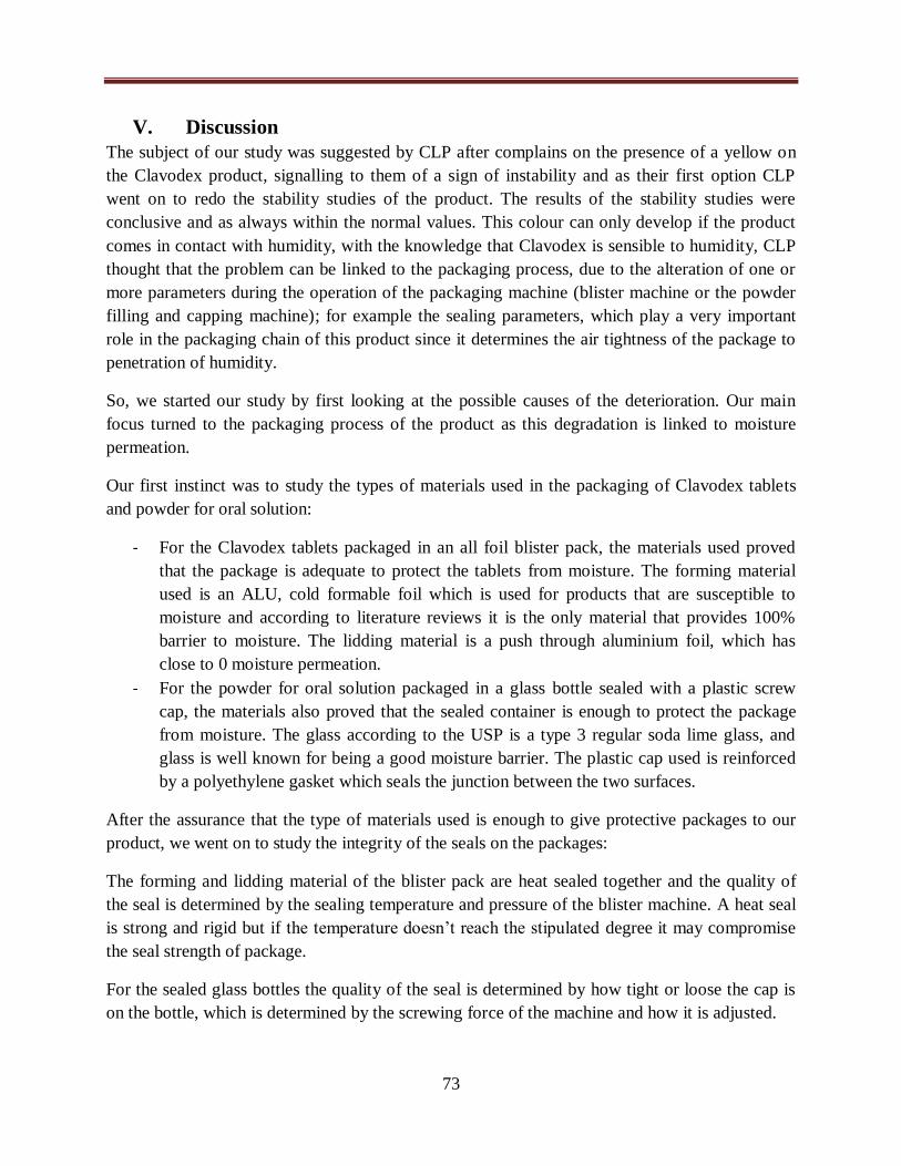
73
V. Discussion
The subject of our study was suggested by CLP after complains on the presence of a yellow on
the Clavodex product, signalling to them of a sign of instability and as their first option CLP
went on to redo the stability studies of the product. The results of the stability studies were
conclusive and as always within the normal values. This colour can only develop if the product
comes in contact with humidity, with the knowledge that Clavodex is sensible to humidity, CLP
thought that the problem can be linked to the packaging process, due to the alteration of one or
more parameters during the operation of the packaging machine (blister machine or the powder
filling and capping machine); for example the sealing parameters, which play a very important
role in the packaging chain of this product since it determines the air tightness of the package to
penetration of humidity.
So, we started our study by first looking at the possible causes of the deterioration. Our main
focus turned to the packaging process of the product as this degradation is linked to moisture
permeation.
Our first instinct was to study the types of materials used in the packaging of Clavodex tablets
and powder for oral solution:
- For the Clavodex tablets packaged in an all foil blister pack, the materials used proved
that the package is adequate to protect the tablets from moisture. The forming material
used is an ALU, cold formable foil which is used for products that are susceptible to
moisture and according to literature reviews it is the only material that provides 100%
barrier to moisture. The lidding material is a push through aluminium foil, which has
close to 0 moisture permeation.
- For the powder for oral solution packaged in a glass bottle sealed with a plastic screw
cap, the materials also proved that the sealed container is enough to protect the package
from moisture. The glass according to the USP is a type 3 regular soda lime glass, and
glass is well known for being a good moisture barrier. The plastic cap used is reinforced
by a polyethylene gasket which seals the junction between the two surfaces.
After the assurance that the type of materials used is enough to give protective packages to our
product, we went on to study the integrity of the seals on the packages:
The forming and lidding material of the blister pack are heat sealed together and the quality of
the seal is determined by the sealing temperature and pressure of the blister machine. A heat seal
is strong and rigid but if the temperature doesn’t reach the stipulated degree it may compromise
the seal strength of package.
For the sealed glass bottles the quality of the seal is determined by how tight or loose the cap is
on the bottle, which is determined by the screwing force of the machine and how it is adjusted.

74
Seeing that the integrity of the seal is affected by the parameters of the machine, we went on to
study the composition, operations and controls of the machines. This enabled us to come up with
flowchart diagrams for both machines. The flowchart diagram represents the different steps of
packaging and it helped us in comparing what must be done and what is done in reality. Our
knowledge of how the machines function enabled us to establish a procedure for the adjustment
of each machine and a procedure for the preparation of samples according to the WVTR method.
To assure that the samples were produced under the right conditions and meet the same quality
the requirements as those required in actual production, we had to:
- Establish procedures : Procedure of adjustment of the blister machine- NMX, Procedure
of the adjustment the powder filling and capping machine RAV 05,Procedure of the
method WVTR
- Verify the conditions during the sample preparation method.
The normal values of temperature and humidity must always be in the given ranges; (between
20- 24 °C for the temperature and less than or equal to 20% for the humidity) in the packaging
room. If the values go beyond these given limits an alarm will sound to warn the operators and
the packaging operation is put on hold until the conditions are adjusted back to normal by the
maintenance team.
From the results of control of parameters of the machines the:
- Temperature of sealing plate, sealing pressure, number of matrix used were all within the
specified values for the blister machine
- Speed of rotation of the tightening head were according to the specification for powder
filling and capping machine
From the results of control of samples produced the:
- Integrity and absence of folds on aluminium, well formed cavities, Integrity of seal, Dye
penetration test of blister samples produced the results obtained were all up to standard
- Integrity of sealed container, Integrity of closure, absence broken bottle or cap of bottle
samples the results conformed to the specifications.
These results confirmed to us that the produced samples had the required seal quality and the
control of the samples reassured us that the samples had been produced according to good
manufacturing practices as well as according to the test method requirements.
After the adjustment of all parameters and verifying controls, we prepared samples of bottles and
blisters according to the WVTR method, respecting procedures

75
The samples were packed and put in storage, until they are send to the testing company. The
industry could not send the samples for testing; due to internal problems, therefore we could not
have the results from WVTR test.

76
Conclusion

77
Pharmaceutical industries are judged according to their capacity to produce products of good
quality that guarantee the safety of the user and meet the stipulated shelf life, and the packaging
of the pharmaceutical product plays an important role in meeting all these requirements. It is
therefore important to perform tests on the packaging materials, the finished packaged product,
as well as researching on the different parameters that can affect the quality of the product. In
this context of searching for permanent improvement in the quality of the Clavodex products at
CLP, we carried out this study on the preparation and validation of procedures for the
adjustments of packaging machines and preparation of samples according to the WVTR method.
This study allowed us to illustrate that the search for quality first passes by the creation of an
adequate environment, where the choice of materials and the packaging operation itself have a
great influence on the quality of the product produced. The packaging equipment and how they
are adjusted also must be reflected on, which leads us to the need to perform a study on the
quality risk management of the packaging process of Clavodex to determine where the real
problem is.
In conclusion the need to perform a WVTR test on the Clavodex products is great as the dye
penetration test method used has proved to be insufficient. It is the results from the WVTR that
will prove if the problem in degradation of Clavodex is due to moisture permeation in the
package.
We recommend CLP to set up a quality risk analysis based on the method Failure Mode and
Effects and Criticality analysis, which allows identification and evaluation of the risk and how to
reduce or make it acceptable therefore, classifying the risks and putting in place the actions to
manage the risks. It is an integral part of an efficient pharmaceutical quality system in the
context of continuous improvement of the quality of their products.

78
Bibliography

79
1. Das PS, Saha P, Krishan, Das R. Pharmaceutical Packaging Technology: A Brief Outline.
Res J Pharm Dos Forms Technol [Internet]. 2018;10(1):23. Available from:
http://www.indianjournals.com/ijor.aspx?target=ijor:rjpdft&volume=10&issue=1&article
=005
2. Ali mohd sohail, Talath F, Syed abdul mubeen, Khale mohd abdul, Mannan A. Recent
Advancements in Pharmaceutical Packaging. Journals, Hum Artic Rev. 2017;(3).
3. Hosseiny A, Ph D. Validation of Pharmaceutical Packaging Lines. :1–4.
4. Bairagi PD, Darekar AB, Gondker SB, Saudagar Rb. Pharmaceutical Packaging
Materials : A Brief Review. 2018;7(2):482–510.
5. Efmhaca. Good Manufacturing Practice Guideline For Pharmaceutical Products. Ethiop
Food, Medician Healthc Adm Control Auth ( EFMHACA). 2014;First Edit(Addis Ababa,
Ethiopia):82–6.
6. Annex 9 Guidelines on packaging for pharmaceutical. World Heal Organ. 2002;(902).
7. Albert DE, Northwood N. Evaluating Pharmaceutical Container Closure Systems. 2004;
8. pharmacopée européenne. 2010;
9. Arsalan A, Naqvi AA, Ahmed FR. International Journal of Pharmaceuticals and Review
Features , Functions and Selection of Pharmaceutical. 2014;(March).
10. Hir le a, C C, Brossard d. pharmacie galénique. 9th ed. Vol. 143. 2003. 74–80 p.
11. Praveen A. World Journal of Pharmaceutical Research. 2014;3(5):344–68.
12. Piringer otto g, Baner albert l, editors. plastic packaging. second. wiley-VCH;
13. Bauer j edward. pharmaceutical packaging handbook. 2009.
14. Balakrishna T, Hanumaiah C, Sciences P. Pharmaceutical Containers And Closures.
2016;3(8):867–79.
15. Journals H, Article R. Recent Advancements in Pharmaceutical Packaging. 2017;(3).
16. Dean DA. BLISTER , Strip And Sachet Packaging.
17. Campbell GA, Vallejo E. Primary Packaging Considerations in Developing Medicines for
Children : Oral Liquid and Powder for Constitution. 2015;52–62.
18. Sengar G, Pranab T. Pharmaceutical Regulatory Agencies and Organizations around the
World: Scope and Challenges in Drug Development. Pharmatutor-Art-1316.
19. Glasby J. Regulatory Aspects Of Pharmaceutical Packaging.
20. Rathore a. S, Bhambure R, Ghare V. Guidance for Industry Guidance for Industry. Anal
Bioanal Chem. 2010;398(1):5.
21. Conference I, Harmonisation ON, Technical OF, For R, Of R, For P, et al. Requirements
For Registration Of Pharmaceuticals For Human Use. 2009;8(August).
22. Organization A. What is ASTM.
23. Cambil-Martín J, Flynn M, Villaverde-GutiIrrez C. Quality assurance of nursing web
sites: Development and implications of the ALEU method. CIN - Comput Informatics
Nurs. 2011;29(9):523–30.
24. Nash robert a, Watchter alfred h. pharmaceutical process validation. third edit. marcel
dekker; 2003.
25. Pilchik R. validating medical packaging. CRC Press LLC; 2002.
26. Manek S. validation of pharmaceutical packaging .pdf. pharma times. 2012;44(02):17.
27. Verma A, Pradesh U. Pharmaceutical Research And Bio-Science. 2014;(August).
28. Nandhakumar L, Dharmamoorthy G, Rameshkumar S, Chandrasekaran S. an overview of
pharmaceutical validation. 2011;1(4):1003–14.
29. Reddy BV, Ujwala P, Sandeep P, Deepthi A. Pharmaceutical Validation-A Review

80
Pharmaceutical Validation – A Review. 2015;(April).
30. Ahuja S, Stephen S, editors. handbook of modern pharmaceutical analysis. In.
31. Gupta PC. Method Validation of Analytical Procedures. 2015;3(1):32–9.
32. Turner M. How to Validate a Packaging Process. 2004;15(2):20–2.
33. Ahir KB, Singh KD, Yadav SP, Patel HS, Poyahari CB. Review Article Overview of
Validation and Basic Concepts of Process Validation. 2014;3(2):178–90.
34. Sci PDAJP. White Paper : Container Closure Integrity Control versus Integrity Testing
during Routine Manufacturing White Paper : Container Closure Integrity Control versus
Integrity Testing during Routine Manufacturing. 2015;(December 2017).
35. C MK, Akhilesh D, Kumar BS. Recent Trends in Pharmaceutical Packaging : A Review.
2012;1(3):1282–92.
36. Hunt BDG. Moisture Permeation of Pharmaceutical Packaging. 2018;
37. Troedel M. An Overview of Package Integrity for Medical Device Manufacturers.
38. Stevenson P. leak detection methods for pharmaceutical blisters.
39. Technologie L. Informations pratiques sur l ’ Hélium. (cuve 2).
40. Hameln S, Herdlitschka C. Container / Closure Integrity Testing Current and coming best
practice.
41. Greene K, Emerson E. eight steps to package integrity. healthcare packaging.
42. Labs N. container closure integrity- dye immersion and bacterial immersion. nelson labs.
43. Richard A, Unither C, Astrazeneca PC. Overview of Packaging Validation for Drug
Products Overview of Packaging Validation for Drug Products. :1–16.
44. Hemi S. advanced leak test methods. assemblymag. 2001.
45. Elmer W. Griese Jr. Moisture and Water Vapor Transmission Rates in Packaging - Cork
Industries, Inc. Cork Tech Talk Blog [Internet]. 2018; Available from:
http://www.corkindustries.com/tech-uv-eb-aqueous-coatings-blog/458-moisture-and-
water-vapor-transmission-rates-in-packaging.html
46. Remmelgas J. Predicting Moisture Uptake in Solid Dosage Packaging. Pharm Technol
[Internet]. 2017;41(1):44–9. Available from: http://www.pharmtech.com/predicting-
moisture-uptake-solid-dosage-packaging?pageID=2
47. Yihong O, Yisheng C, Geoff g z chang, editors. developing solid oral dosage forms. 1st
ed. 2009. 907 p.
48. Lockhart H, Albert Paine FA. Packaging of pharmaceuticals and healthcare products.
1996. 1–38 p.
49. Troedel ML. methods for testin high barrier materials. (1).
50. Hartvigsen AA. Automatic Permeability Testing : The Challenges and Solutions.
51. Requirements ST. Water Vapor Permeability Tester for Medicine Package Materials
Using Electrolytic Analysis. labthink. 2014;1–6.
52. Stevens M, Tuomela S, Mayer D. Water Vapor Permeation Testing of Ultra-Barriers :
Limitations of Current Methods and Advancements Resulting in Increased Sensitivity. :1–
3.
53. Nisato G, Hannes K. experimental comparison of high performance water vapour
permeation measurement methods. Org Electron. 2014;
54. Inc M. Which Provides More Accurate Test Results ? mocon inc. 2017;
55. Pilchik R. Blister Packaging , Part I. 2000;(November).
56. Berget L. le conditionnement des médicaments. 2015.

81
Annexes
Annexe 1: Preparation of samples of bottles according to the WVTR method
Water Vapour Transmission Rate Measurement on Sealed Containers –
Sample Preparation. 1. Prepare and if required clean 10 -20 bottles and closures as they would be used in production.
Do not use paper labels, but label each with a marker pen.
2. Place a piece of tissue paper or cotton wool into the bottle, to loosely occupy approximately
1/4 of the volume of the bottle. It is important that the material does not contain any water-
soluble components, such as lanolin etc.
3. Add roughly 1/10 of the volume of the container in de-ionized or distilled water. So for a
200ml bottle, add 20 ml water. The amount of water is not critical, as it is there only to create
a humid environment for the test.
4. Ensure the threads or sealing surface of the bottle are dry and close the bottle in the same
way as it is carried out in production. Ideally this should be done on a production line.
Alternatively it should be torqued or sealed in the laboratory under similar conditions to
those in production.
5. Pack the bottles upright, and if glass, separated so that they are not broken. Desiccant is not
necessary, but placing the samples in a plastic bag is helpful, especially if they are travelling
by air.
6. Include all serial numbers and descriptions as are required on the report in the covering note,
also the temperature required for the test. Although this is most commonly 30°C, please
confirm.

82
Annexe 2: Procedure of use of blister machine NMX
PROCEDURE D’UTILISATION NMX : I. OBJET :
Présentation de la thermo formeuse nMX, de ses différents composants, ainsi que le champ d’actions
et les niveaux d’intervention des différents opérateurs; à fin d’assurer une utilisation correcte et un
nettoyage (entretien) efficace de cet appareil.
II. DOMAINE D’APPLICATION : Cette procédure s’applique sur la thermo formeuse « nMX » au niveau de l’atelier de blisterage
(BOX: 309).
III. RESPONSABILITE : L’operateur de la machine est responsable de l’application de cette procédure. Le superviseur de
production, le responsable de production ainsi que les agents de maintenance veillent à l’application
de cette procédure.
IV. REFERENCES ET DOCUMENTS ASSOCIES :
A. REFERENCE : Manuel d’instructions nMX : Révision. DEC 2014.
B. DOCUMENTS ASSOCIES : Log book de la thermo formeuse nMX.
V. DEFINITIONS ET ABREVIATIONS :
1. DEFINITIONS : Thermo formeuse nMX: la thermo formeuse nMX est une machine automatique conçue pour
conditionner en « blister » différents médicaments solides oraux. Sa capacité de production est
d’environ 500 blister/min, dans la mesure où les dimensions et la forme du produit le permettent.
(figure: photo)
Fabricant : Partena
Modèle : nMX
Matricule : MX.211
Année de fabrication : 2014
Ruban : le matériel de formage, le matériel de couverture et les deux quand ils sont soudés
ensemble qui avancent le long de la machine.
Le format : l’ensemble de un ou plusieurs blisters existant dans un pas de formage pour le
conditionnement de un ou plusieurs produits.
Pas de formage : la zone sur le ruban qui, à chaque cycle machine, est intéressée par le formage et
la fermeture des alvéoles (environs 6 blisters/cycle).
2. ABREVIATIONS : ALU : Aluminium
PVC : Polychlorure de vinyle

83
VI. LE CONTENU :
1. DESCRIPTION GENERALE :
A) COMPOSANTS DE LA MACHINE :
La machine est équipée des unités suivantes :
Unité de formage : déformation à chaud ou à froid du matériau de formage, et comprend les
groupes suivants:
Transmission unité de formage ;
Porte bobine matériau de formage ;
Rouleaux de transfert matériau de formage ;
Pince d’entrée poste de préchauffage ;
Poste de préchauffage ;
Poste de formage.
Unité de transfert pinces et chargeurs : alimentation des produits dans les alvéoles individuels,
et comprend les groupes suivants :
Pince de sortie poste de formage ;
Transmission unité de transfert pinces et chargeurs ;
Système de transfert pinces et chargeurs.
Unité de scellage : thermoscellage du matériau d’operculage avec le matériau de formage, et
comprends les groupes suivants :
Transmission unité de scellage ;
Porte bobine matériau d’operculage ;
Poste de scellage ;
Poste de refroidissement ;
Pince de sortie poste de scellage.
Unité de découpe : découpe de la bande thermoscellée en blisters, et comprend les groupes
suivants:
Transmission unité de découpe ;
Rouleaux de contraste ;
Poste de perforation rotative ;
Pince d’entrée poste de découpe ;
Poste de codification ou perforation intermittent ;
Poste de découpe ;
Système de prise et lâcher blister ;
Système de transfert blisters.

84
B) ZONES DE TRAVAIL :
Toute zone à proximité d’une machine, où les opérateurs sont appelés à accomplir leurs tâches, est
appelée zone de travail, et comprend :
Zone A : Mise sous/hors tension de la machine ;
Commande du fonctionnement en mode automatique ou en mode manuel ;
Remplacement des bobines du matériau de formage et d’operculage ;
Réarmement de la machine en cas d’arrêts.
Zone B : Chargement du produit dans le préalimentateur.
Zone C : Réarmement de la machine en cas d’arrêt provoqué par bourrage de blisters sur le tapis de
transfert.
(Figure p 12 chap3)
C) INTERFACE OPERATEUR-MACHINE :
Moyen de communication entre l’operateur et la machine, comprend :
Panneau de mise sous/hors tension de la machine.
Clavier de commande regroupant les boutons poussoirs, les sélecteurs d’actionnement et de
réglage de la machine, dans lequel le panneau opérateur est intégré. (sélections : figure 15/16/17 page
15/16 chapitre 8 ASEM)
Clavier de commande dans la zone de sortie blisters permettant l’arrêt en phase et l’arrêt d’urgence
(position ½ p83 chap8) dans cette zone de travail.
(Figure page 16 chap3)
D) DISPOSITIFS D’AVERTISSEMENT ET DE SIGNALISATION :
La machine est équipée de dispositifs d’alerte et de signalisation suivants :
Signalisation sonore : générée par une sonnerie et s’active :
En appuyant sur le bouton de marche automatique ;
Lorsque le niveau minimal produit et matériau de formage et/ou d’operculage est atteint.
Signalisation lumineuse : signal lumineux sur la verrine à couleur :
Lumière rouge : arrêt à cause d’une alarme ;
Lumière orange : attente de redémarrage de machine en aval ;
Lumière verte : machine en marche ;
Lumière blanche : machine sous tension

85
Pictogrammes : Avertissement : rappel sur des arguments significatifs
Danger d’électrocution
Danger de nature mécanique
Danger de nature mécanique
Danger pour transport de charges suspendues
Danger d’écrasement des mains
Danger de coupures aux mains
SYSTEMES DE CONTROLE DE LA THERMOFORMEUSE : 1. Contrôle produit hors alvéole S43 : a pour fonction de détecter les produits, les fragments de
produits ou les corps étrangers présents sur la bande formée ou, mal positionnés dans l’alvéole. Cette
tâche de contrôle est effectuée par effleurage du matériau de formage par une lame mobile (pos 1 p38
chap8+ figure).
2. Contrôle présence matériau de formage B0 : (pos7 p14 chap8) qui arrête la machine en phase
lorsque la bobine est épuisée en affichant un message d’alarme.
3. Contrôle niveau minimal matériau de formage B1 : (pos6) qui alerte l’opérateur du changement
bobine imminent par un signal sonore et lumineux ainsi qu’un message d’alarme affiché sur l’écran.
4. Contrôle jonction sur le matériau de formage B6 : (pos9 p14 chap8) qui détecte la présence du
ruban adhésif thermosoudable utilisé pour la jonction des deux bouts des bobines. La cellule
photoélectrique transmet l’information à l’automate ; celui-ci commande ensuite le rejet des blisters
et l’arrêt du chargeur. Le réglage de la sensibilité de cette cellule s’effectue par l’intermédiaire du
bouton (pos10).
5. Contrôle présence matériau d’operculage S30 : (pos7 p42 chap8) arrêtant la machine en phase
lorsque la bobine est épuisée, un message d’alarme est affiché sur l’écran.
6. Contrôle niveau minimal matériau d’operculage B3 : (pos6) qui alerte l’opérateur du
changement de bobine par un signal sonore et lumineux ainsi que la visualisation d’un message
d’alarme.
7. Contrôle jonction sur le matériau d’operculage B7 : (pos8) qui détecte la présence du ruban
adhésif thermosoudable utilisé pour la jonction des deux bouts des bobines. La cellule
photoélectrique transmet l’information à l’automate ; celui-ci commande ensuite le rejet des blisters
et l’arrêt du chargeur. Le réglage grosso-modo de la sensibilité de la cellule s’effectue à la fois, par
l’intermédiaire du bouton (pos12).
8. Contrôle pas sur la pince de sortie poste de scellage : Ce dispositif détecte la position correcte
du matériau formé (ce matériau doit avancer d’un pas « P » à chaque cycle de machine) ainsi que la
présence d’éventuels objets entre les plaques de scellage inférieurs et supérieurs, par l’intermédiaire
de quatre capteurs (S33, S33A, S33B, S33C). A chaque fois que l’un de ces quatre capteurs
s’éteigne, la machine s’arrête en phase, le poste de scellage s’ouvre immédiatement et un message
d’alarme s’affiche sur l’écran.
9. Contrôle présence de produit avec vidéo caméra « SEA VISION»: compare le pas de formage
roulant en dessous des télé-caméras, durant le cycle productif, avec le « pas de formage étalon ». en
cas de discordance ou de

86
valeurs hors plage, le système localise les blisters défectueux et génère les signaux d’éjection.
10. Contrôle nombre de pas entre le contrôle présence de produit et l’éjection blisters S68 : qui
vérifie que le nombre de pas entre l’axe de lecture du dispositif de contrôle présence du produit et
l’axe du poste de découpe correspond à celui définie par le format en cours de production. Il est
composé d’une roue monté sur un chariot coulissant (pos p52 chap8) détectant l’anse maximale et
minimale créée par la bande thermosoudée à l’entrée du poste de découpe. La thermoformeuse
s’arrête en phase et un message d’alarme s’affiche à chaque fois que l’excursion de la roue dépasse
les valeurs seuils.
11. Système d’éjection des blisters vides et incomplets : a pour fonction de détourner les blisters
non conformes, détectés par le dispositif de contrôle présence de produit dans le convoyeur (pos1
p74 chap8). Il est pourvu de :
une cellule photoélectrique B7D (pos2 p74 chap8) qui détecte le passage et autorise le rejet,
positionnée sur un support réglable. Un réglage grosso-modo de la sensibilité de la cellule détermine
l’espace séparant entre deux blisters. Une éjection de blisters bons pourrait être justifiée par une
double lecture du blister résultante d’un réglage trop soigné de la sensibilité de cette cellule ;
un dispositif d’éjection à jet d’air et un dispositif de détournement (pos4 et 5), qui s’activent en
rejetant les blisters vides ou incomplets.
12. Système d’interception des blisters non éjectés : a pour fonction de détecter et dévier, sur le
convoyeur (pos4 p76) les blisters vides ou incomplets n’ayant pas été éjectés dans le convoyeur
(pos3). Il est composé de :
Trois cellules photoélectriques B4C, B4D (pos8) et B9D (pos9) qui arrêtent la machine en phase
en générant une alarme, lors de l’interception d’un passage de blisters vides ou incomplets, et
autorisent le détournement ;
Un dispositif de rejet à jet d’air (pos2) qui détourne les blisters sur le convoyeur de ramassage
(pos4).
13. Système de détournement des blisters bons : ce système s’active à l’arrêt de la machine en aval
et a pour fonction de dévier les blisters bon sur le convoyeur (pos 5 p78). Il est muni d’une cellule
photoélectrique B1C (pos7) qui autorise le détournement ainsi qu’un dispositif de rejet à jet d’air qui
détourne les blisters sur le convoyeur de ramassage.
14. Dispositifs de contrôle niveau minimal produit :
Au niveau du pré-alimentateur : le détecteur B2 (pos2 p32 chap8) alerte l’opérateur, par un
signal sonore et un message d’alarme

87
lorsque l’approvisionnement de la trémie de chargement (position), descend en dessous du niveau
minimal préétabli.
Au niveau du chargeur à plaque : lorsque le niveau produit dans le chargeur est insuffisant, le
dispositif de contrôle S47 (pos2 p34 chap8) active le vibreur linéaire (pos4 p32 chap8) pour convoyer
le produit à l’intérieur du chargeur. Une fois le niveau est rétabli, le vibreur s’arrête.
2. MODE D’UTILISATION :
A) VERIFICATIONS PRELIMINAIRES ET MONTAGE :
Avant chaque mise en marche, l’operateur se doit d’effectuer les opérations préliminaires dans
l’ordre suivant :
Vérifier que tous les carters ainsi que les protecteurs mobiles et fixes de sécurité sont fermés ;
Vérifier l’alimentation de la machine ;
Mettre la machine sous tension (tourner le sélecteur à clé vers la droite et appuyer sur la touche
lumineuse blanche) (figure p86 chap8);
Vérifier la pression d’air (6-8 bars) et d’eau (1-2.5 bars) et qu’il n’y a pas de fuite ;
Vérifier la propreté du préalimentateur (figure p32 chap8) puis vérifier et monter le canal de
descente, la trémie de chargement (photo), le rouleau d’arasement et le chargeur à plaque du produit
canalisable (figure p34 chap8 ou p16/17/60 chap9);
Appuyer sur la touche reset en bleu (bouton poussoir de réarmement) sur le clavier de commande
(figure p85/86 chap8) ;
S’identifier dans le panneau operateur en utilisant l’accès utilisateur Admin (mot de passe :
Ad1023) (figure 6/7/8/9 page 8/10 chapitre 8 ASEM)
Effectuer un changement de format si nécessaire (voir procédure de changement de format) et/ou
un changement de poinçons (nouveau lot).
Attendre que les températures de formage (cas d’un format ALU/PVC) aient atteint (130˚) et celle
du scellage (170˚) ;
Appuyer sur le bouton poussoir de mise en marche en mode automatique pour commencer le cycle
productif.
B) MISE EN MARCHE :
i. Mode de marche : Deux modalités de marche sont possibles sur la thermoformeuse :
Marche en mode automatique : la thermoformeuse marche en continu suivant les paramètres
saisis. l’actionnement se fait en appuyant sur le bouton de marche en mode automatique (position).
Marche en mode manuel : la thermoformeuse exécute uniquement quelques phases individuelles
du cycle de conditionnement standard. Ce mode de marche est habilité en tournant vers la droite le
sélecteur de marche par à-coups (position).
L’actionnement se fait en appuyant sur la touche mobile de marche par à-coups positionné sous le
plan de chargement. (image des positions p82/85 chap8)
ii. Essais à vide : L’essai à vide permet de s’assurer du bon fonctionnement de la machine, vérifier la découpe des
blisters, le marquage, le formage, le scellage ainsi que le positionnement correcte des bobines. Il
s’effectue comme suite :

88
Désactiver la camera ;
Désactiver l’accouplement en aval ;
Désactiver le chargeur à plaque ;
Diminuer la vitesse ;
Appuyer sur le bouton mise en marche en mode automatique et effectuer les vérifications
nécessaires.
Arrêter la machine en appuyant sur le bouton d’arrêt en phase (position).
iii. Démarrage du lot : Avant de démarrer proprement le lot, charger le produit dans le préalimentateur et activer le
chargeur. Appuyer sur le bouton marche, effectuer un essai en présence du produit et un test
d’étanchéité.
Effectuer l’opération de conditionnement primaire (blisterage) sans oublier les contrôles de
conformité nécessaires, à savoir :
Un test d’étanchéité de 6 blisters (selon le format adopté) chaque 30 minutes ;
Un contrôle visuel de 18 blisters chaque 15 minutes.
iv. Réglage : Pendant l’opération de conditionnement, l’operateur de la machine est habilité à effectuer certains
réglages sur la thermoformeuse ; entre autre :
La vitesse de la machine ;
L’intensité de la vibration du préalimentateur lorsque le niveau du produit dans le chargeur n’est
pas adéquat ;
Le capteur de niveau du produit qui contrôle le fonctionnement du préalimentateur ;
La vitesse du rouleau d’arasement qui oriente et convoie le produit dans les canaux de descente.
(Page 15/16 chapitre 8 ASEM tableau réglages usuels position 12/1/5)
v. Fin du lot et mise hors tension de la machine : Quand le produit d’un lot s’épuise, appuyer sur le bouton d’arrêt en phase pour arrêter la machine
et effectuer un vide de ligne (voir procédure de vide de ligne).
En fin de journée, après épuisement du produit présent dans le préalimentateur, mettre la machine
hors tension, après l’avoir arrêté, en tournant à gauche le sélecteur de tension. Attendre 15 minutes
avant de couper/isoler le circuit de refroidissement.
Remarque : Après avoir éteint le panneau operateur, il est nécessaire d’attendre au moins 5 minutes
avant de pouvoir le rallumer.
vi. Cas particuliers : Procédure de changement de poinçons :
Avant de commencer un nouveau lot effectuer un changement de poinçons selon les étapes suivantes
:
Desserrer puis retirer le moule de codage ;
A l’aide d’une clé Allen, dévisser les vis (figure p64 chap8) sur le porte-poinçons pour libérer les
poinçons ;
Retirer les anciens poinçons à l’aide d’une pince ;

89
Placer les nouveaux poinçons selon les instructions du dossier de conditionnement ;
Remplir les espaces vides avec les cales ;
Serrer les vis du porte-poinçons puis placer le moule de codage et serrer la manette.
Procédure de changement de bobines :
Lorsque la machine est à l’arrêt en phase pour épuisement de bobine ou au vouloir de l’operateur,
adopter la procédure suivante pour remplacement de :
Bobine-matériau de formage : (ALU/PVC) Bloquer le matériau de formage en tournant le levier (position) en sens horaire ;
Exécuter la découpe du matériau de formage en agissant sur le poigné (position) ;
Débloquer manuellement la bobine épuisée sur l’arbre de détente et l’enlever ;
Installer la nouvelle bobine et s’assurer qu’elle soit bien centrée ;
Dérouler le matériau, en suivant le schéma indiqué sur la machine, jusqu’à le faire passer en
dessous du rouleau de blocage (position) ;
Bloquer l’extrémité initiale de la bobine en tournant le levier (position) en sens horaire, puis
effectuer la découpe en agissant sur le poigné;
Joindre les deux extrémités à l’aide d’un ruban adhésif thermoformable et débloquer le matériau
en tournant les leviers en sens inverse ;
Démarrer à petite vitesse pour éliminer la jonction, puis reprendre le cycle productif. (figure
p13/14 chap8)
Bobine-matériau d’operculage : (ALU) Ouvrir le protecteur mobile face au porte bobine ;
Effectuer une découpe rectiligne du film d’operculage ;
Débloquer la bobine épuisée sur l’arbre expansible et l’enlever ;
Insérer la nouvelle bobine et s’assurer qu’elle soit centrée et la bloquer ;
Exécuter la découpe rectiligne du film de la nouvelle bobine, puis superposer les deux extrémités
et les joindre à l’aide d’un ruban adhésif thermoformable et le dérouler en suivant le schéma indiqué
sur la machine
En cas de matériau d’operculage ayant des spots de repère pour le dispositif de centrage
d’impression, effectuer la jonction en superposant les extrémités de telle façon à faire coïncider les
deux spots de repère ;
Soulever manuellement le balancier pour enrouler et tendre le matériau, puis relâcher ;
Fermer le protecteur mobile, démarrer à petite vitesse pour éliminer la jonction, puis reprendre le
cycle productif. (figure p42 chap8)
Procédure de changement de format :
Avant d’effectuer un changement de format, déterminer, à l’aide d’une fiche de changement de
format, les parties à remplacer, s’approvisionner de ces parties ainsi que de matériaux de
conditionnement et de produits.
Adopter la procédure suivante pour effectuer un changement de format :
Exclure les dispositifs de contrôle présence de produit, le fonctionnement du chargeur, le poste
de scellage ainsi que l’accouplement en aval ;
Démonter la grille, le chargeur à plaques et les dispositifs de contrôle pour remplacer les pièces
du format à adopter;

90
Enlever les matériaux de conditionnement en les coupant en amant du poste de formage et de
scellage ;
Démonter l’unité de formage et de scellage, effectuer un changement de poinçons, de matrices,
de plaques de formage et de scellage, ainsi que les autres pièces du format. Les monter dans le sens
inverse du démontage ;
Régler le pas machine en se servant du connecteur pour MARCHE PAR A COUPS ;
Introduire les matériaux de conditionnement correspondants au format ainsi que les dispositifs
de contrôle et créer la ligne ;
Démonter les rouleaux et la plaque de contraste, le guide de frictionnage, le poste de perforation,
le poste de découpe, l’outil de codage et le disque de format ;
Démonter la tige de contrôle nombre de pas ;
Monter l’unité de découpe dans le sens inverse du démontage ;
Insérer la bande thermosoudée dans l’unité de découpe, régler la pince pour centrer la découpe ;
Monter la grille et le chargeur à plaque correspondant au format ;
Régler les guides du groupe de courroies sur la machine en aval ;
Sélectionner le format monté à présent sur le dispositif de contrôle présence de produit puis
activer le mode automatique du chargeur ;
Activer le préalimentateur, le chargeur et l’accouplement en aval ;
Introduire le produit dans le préalimentateur et le chargeur. La machine est prête pour la
production.
Autres : gestion des principaux
problèmes rencontrés pendant les
opérations de blisterage : Problèmes
:
Actions correctives :
Coupure de courant
Attendre 5 minutes avant la remise
sous tension de la machine.
Alarme fin matériau de formage
et/ou d’operculage
Remplacer les bobines épuisées
selon la procédure de changement de
bobines.
Effectuer une jonction du film en
cas de déchirure
Produit hors alvéole
Dégager le plan machine des corps
étrangers/ fragments produits et loger
correctement le produit dans les
alvéoles.
Vérifier l’emplacement du produit
sous la camera de contrôle.

91
Surcharge scellage sur les capteurs
S33
Centrer le film et enlever l’objet
oublié entre les deux plaques de
scellage.
Nettoyer la plaque de scellage,
après refroidissement, et contrôler qu’il
n’y a plus de produits hors alvéole.
Arrêt de la machine en aval
Redémarrer la machine en aval ou
désactiver l’accouplement en aval.
Alimentation irrégulière du produit
dans la trémie
Vérifier s’il y a présence d’un
fragment du produit coincé dans la
plaque de canalisation et l’enlever.
Vérifier la charge de la trémie puis
positionner le capteur S47 (position 2
p34 chap8) pour régler l’alimentation
de la plaque ou agir sur la vitesse de
vibration du bol.
Distribution irrégulière ou manque du
produit dans les alvéoles
Vérifier la position et ou le
fonctionnement du chargeur.
Vérifier la présence d’un fragment
du produit dans la plaque de
distribution du produit (photo) et
l’enlever.
Bourrage entrée magasin blisters
B16 (position photo arrière et p80
chap8)
Arrêter la machine, vérifier le
magasin de blisters et le dégager du
bourrage.
Anomalie de flux des blisters sur les
convoyeurs de sortie B5D
Ejection de blister incomplet non
effectuée. B9D B4D B9D
Vérifier à l’endroit des capteurs
indiqués dans le message d’alarme, et
les vider de blisters.
Vérifier la position des capteurs.
Eliminer la cause et appuyer sur le
bouton de réarmement et mise en
marche de la machine.
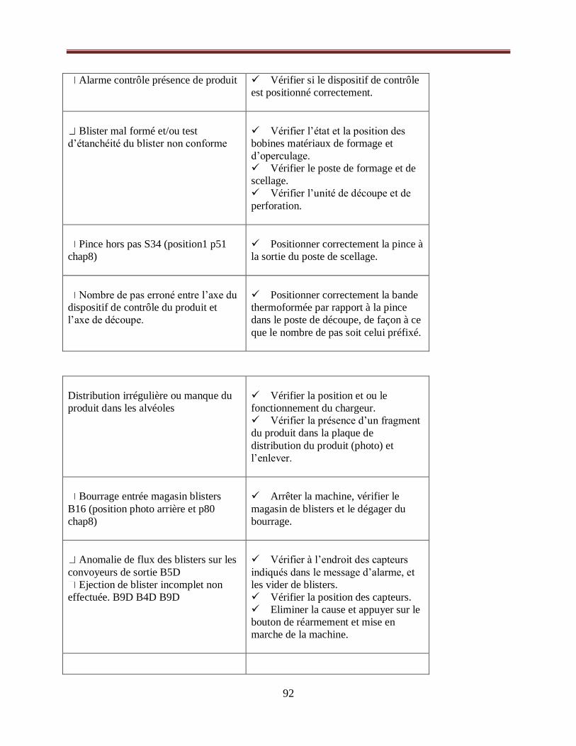
92
Alarme contrôle présence de produit
Vérifier si le dispositif de contrôle
est positionné correctement.
Blister mal formé et/ou test
d’étanchéité du blister non conforme
Vérifier l’état et la position des
bobines matériaux de formage et
d’operculage.
Vérifier le poste de formage et de
scellage.
Vérifier l’unité de découpe et de
perforation.
Pince hors pas S34 (position1 p51
chap8)
Positionner correctement la pince à
la sortie du poste de scellage.
Nombre de pas erroné entre l’axe du
dispositif de contrôle du produit et
l’axe de découpe.
Positionner correctement la bande
thermoformée par rapport à la pince
dans le poste de découpe, de façon à ce
que le nombre de pas soit celui préfixé.
Distribution irrégulière ou manque du
produit dans les alvéoles
Vérifier la position et ou le
fonctionnement du chargeur.
Vérifier la présence d’un fragment
du produit dans la plaque de
distribution du produit (photo) et
l’enlever.
Bourrage entrée magasin blisters
B16 (position photo arrière et p80
chap8)
Arrêter la machine, vérifier le
magasin de blisters et le dégager du
bourrage.
Anomalie de flux des blisters sur les
convoyeurs de sortie B5D
Ejection de blister incomplet non
effectuée. B9D B4D B9D
Vérifier à l’endroit des capteurs
indiqués dans le message d’alarme, et
les vider de blisters.
Vérifier la position des capteurs.
Eliminer la cause et appuyer sur le
bouton de réarmement et mise en
marche de la machine.
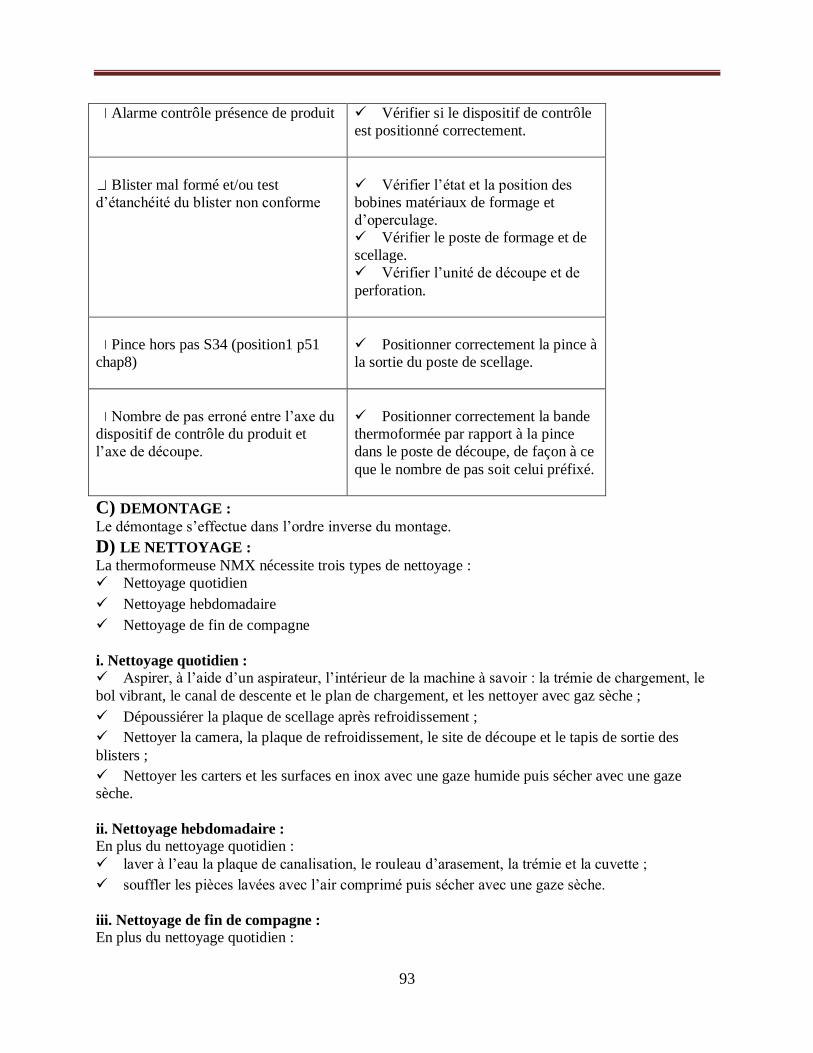
93
Alarme contrôle présence de produit
Vérifier si le dispositif de contrôle
est positionné correctement.
Blister mal formé et/ou test
d’étanchéité du blister non conforme
Vérifier l’état et la position des
bobines matériaux de formage et
d’operculage.
Vérifier le poste de formage et de
scellage.
Vérifier l’unité de découpe et de
perforation.
Pince hors pas S34 (position1 p51
chap8)
Positionner correctement la pince à
la sortie du poste de scellage.
Nombre de pas erroné entre l’axe du
dispositif de contrôle du produit et
l’axe de découpe.
Positionner correctement la bande
thermoformée par rapport à la pince
dans le poste de découpe, de façon à ce
que le nombre de pas soit celui préfixé.
C) DEMONTAGE :
Le démontage s’effectue dans l’ordre inverse du montage.
D) LE NETTOYAGE :
La thermoformeuse NMX nécessite trois types de nettoyage :
Nettoyage quotidien
Nettoyage hebdomadaire
Nettoyage de fin de compagne
i. Nettoyage quotidien : Aspirer, à l’aide d’un aspirateur, l’intérieur de la machine à savoir : la trémie de chargement, le
bol vibrant, le canal de descente et le plan de chargement, et les nettoyer avec gaz sèche ;
Dépoussiérer la plaque de scellage après refroidissement ;
Nettoyer la camera, la plaque de refroidissement, le site de découpe et le tapis de sortie des
blisters ;
Nettoyer les carters et les surfaces en inox avec une gaze humide puis sécher avec une gaze
sèche.
ii. Nettoyage hebdomadaire : En plus du nettoyage quotidien :
laver à l’eau la plaque de canalisation, le rouleau d’arasement, la trémie et la cuvette ;
souffler les pièces lavées avec l’air comprimé puis sécher avec une gaze sèche.
iii. Nettoyage de fin de compagne : En plus du nettoyage quotidien :

94
Toutes les pièces démontables sont lavées à l’eau, puis soufflées et séchées ;
Désinfecter les parties du format en contact directe avec le produit à l’aide d’une gaze humidifié
par une solution détergente compatible avec le matériau à nettoyer.
E) VIDE DE LIGNE :
A chaque fin de lot, l’opérateur doit procéder de la manière suivante :
Vider la trémie de chargement, le bol vibrant et le canal de descente ;
Vider le plan de chargement et le tapis convoyeur de blisters ;
Vider la zone de marquage blisters et changer les poinçons ;
Vider les corbeilles de récupération du déchet de découpe et de blisters vides ;
Vider les bacs de reblistère et de comprimés non conformes ;
Vérifier le vide sur toute la zone de travail de la machine et en dessous de celle-ci.
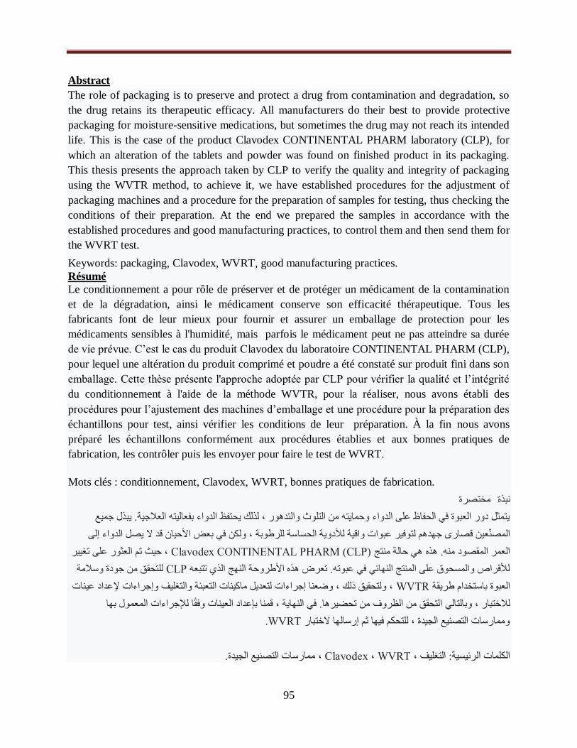
95
Abstract
The role of packaging is to preserve and protect a drug from contamination and degradation, so
the drug retains its therapeutic efficacy. All manufacturers do their best to provide protective
packaging for moisture-sensitive medications, but sometimes the drug may not reach its intended
life. This is the case of the product Clavodex CONTINENTAL PHARM laboratory (CLP), for
which an alteration of the tablets and powder was found on finished product in its packaging.
This thesis presents the approach taken by CLP to verify the quality and integrity of packaging
using the WVTR method, to achieve it, we have established procedures for the adjustment of
packaging machines and a procedure for the preparation of samples for testing, thus checking the
conditions of their preparation. At the end we prepared the samples in accordance with the
established procedures and good manufacturing practices, to control them and then send them for
the WVRT test.
Keywords: packaging, Clavodex, WVRT, good manufacturing practices.
Résumé
Le conditionnement a pour rôle de préserver et de protéger un médicament de la contamination
et de la dégradation, ainsi le médicament conserve son efficacité thérapeutique. Tous les
fabricants font de leur mieux pour fournir et assurer un emballage de protection pour les
médicaments sensibles à l'humidité, mais parfois le médicament peut ne pas atteindre sa durée
de vie prévue. C’est le cas du produit Clavodex du laboratoire CONTINENTAL PHARM (CLP),
pour lequel une altération du produit comprimé et poudre a été constaté sur produit fini dans son
emballage. Cette thèse présente l'approche adoptée par CLP pour vérifier la qualité et l’intégrité
du conditionnement à l'aide de la méthode WVTR, pour la réaliser, nous avons établi des
procédures pour l’ajustement des machines d’emballage et une procédure pour la préparation des
échantillons pour test, ainsi vérifier les conditions de leur préparation. À la fin nous avons
préparé les échantillons conformément aux procédures établies et aux bonnes pratiques de
fabrication, les contrôler puis les envoyer pour faire le test de WVRT.
Mots clés : conditionnement, Clavodex, WVRT, bonnes pratiques de fabrication.
مختصرة نبذة
ميع جية. يبذل جيتمثل دور العبوة في الحفاظ على الدواء وحمايته من التلوث والتدهور ، لذلك يحتفظ الدواء بفعاليته العلا
دواء إلى المصنّعين قصارى جهدهم لتوفير عبوات واقية للأدوية الحساسة للرطوبة ، ولكن في بعض الأحيان قد لا يصل ال
، حيث تم العثور على تغيير Clavodex CONTINENTAL PHARM (CLP)هي حالة منتج العمر المقصود منه. هذه
وسلامة للتحقق من جودة CLPللأقراص والمسحوق على المنتج النهائي في عبوته. تعرض هذه الأطروحة النهج الذي تتبعه
عداد عينات بئة والتغليف وإجراءات لإ، ولتحقيق ذلك ، وضعنا إجراءات لتعديل ماكينات التع WVTRالعبوة باستخدام طريقة
لمعمول بها للاختبار ، وبالتالي التحقق من الظروف من تحضيرها. في النهاية ، قمنا بإعداد العينات وفقاً للإجراءات ا
.WVRTوممارسات التصنيع الجيدة ، للتحكم فيها ثم إرسالها لاختبار
ممارسات التصنيع الجيدة.، Clavodex ، WVRTالكلمات الرئيسية: التغليف ،

96