the use of water cooling during the continuous casting of steel
TRANSCRIPT
The Use of Water Cooling during the Continuous Castingof Steel and Aluminum Alloys
J SENGUPTA BG THOMAS and MA WELLS
In both continuous casting of steel slabs and direct chill (DC) casting of aluminum alloy ingots wateris used to cool the mold in the initial stages of solidification and then below the mold where it isin direct contact with the newly solidified surface of the metal Water cooling affects the productquality by (1) controlling the heat removal rate that creates and cools the solid shell and (2) gener-ating thermal stresses and strains inside the solidified metal This work reviews the current state-of-the-art in water cooling for both processes and draws insights by comparing and contrasting thedifferent practices used in each process The heat extraction coefficient during secondary coolingdepends greatly on the surface temperature of the ingot as represented by boiling water-cooling curvesThus the heat extraction rate varies dramatically with time as the slabingot surface temperaturechanges Sudden fluctuations in the temperature gradients within the solidifying metal cause thermalstresses which often lead to cracks especially near the solidification front where even small tensilestresses can form hot tears Hence a tight control of spray cooling for steel and practices such asCO2 injectionpulse water cooling for aluminum are now used to avoid sudden changes in the strandsurface temperature The goal in each process is to match the rate of heat removal at the surface withthe internal supply of latent and sensible heat in order to lower the metal surface temperaturemonotonically until cooling is complete
I INTRODUCTION
CONTINUOUS casting processes for both steel and alu-minum alloys were developed several decades ago to pro-duce shapes for subsequent semifabrication processes suchas extrusion or rolling As-cast product shapes include bil-lets (square cross section with thickness less than 150 to175 mm for steel) thick slabsingots (wide rectangular crosssection with thickness between 50 and 300 mm for steeland up to 500 to 750 mm for aluminum alloys) thin slabs(thickness between 50 and 75 mm for steel) strips (thick-ness between 1 and 12 mm for both steel and aluminumalloys) and roundsextrusion billets (100- to 500-mmdiameter for both steel and aluminum alloys) In recentdecades a dramatic growth of this primary metal process-ing technology has been realized in both steel and aluminumindustries owing to a substantial increase in yield energysavings and productivity over static casting However thetechnological advancement has taken distinctly different routesfor these two metal industries Over the years the castingprocedures for steel and aluminum alloy products have devel-oped distinctive features in terms of casting practices machin-ery and process and quality control methodologies
The productivity of both processes is controlled by the cast-ing speed so higher speeds are always sought However thecasting speed cannot be increased arbitrarily for several rea-sons[1] First the resulting increase in depth of the liquid pooland surface temperature of the strand prolongs the solidifica-
tion process and increases the cooling requirements In extremecases the structurally weak solid shell may rupture leading toa ldquobreakoutrdquo of liquid metal below the mold or to excessivebulging if containment is exceeded for larger sections Sec-ond higher casting speeds often lead to cracks caused by thehigher thermal stresses The practical range of operating speedsdepends on alloy composition and product geometry For steelslabs the casting speed increases with decreasing thicknessfrom 001 ms1 (for 300-mm blooms) to over 008 ms1 (for50-mm thin slabs) Owing to cracking difficulties during start-up aluminum alloy ingots and billets are cast at much lowerspeeds increasing from 000075 to 0001 ms1[2] to steadyspeeds ranging from 0001 to 0003 ms1[3]
The continuous casting machinery is comprised of the moldand secondary water-cooling systems These are designed toextract superheat from the incoming liquid metal (5 pct ofthe total heat content in the metal) latent heat of fusion at thesolidification front (20 pct of total heat content) and heatof phase transformation and sensible heat (75 pct of thetotal heat content) from the solidified metal However thecooling system features for casting steel and aluminum alloysare very different as schematically illustrated by Figures 1(a)[4]
(for steel) and (b)[56] (for aluminum alloys)In the conventional continuous (or strand) casting of steel
shown in Figure 1(a) liquid steel flows from the bottom ofa ladle into a small intermediate vessel known as the tundishIt leaves the tundish bottom through a submerged nozzleaccording to the position of a stopper-rod or slide-gate flowcontrol system The liquid flow is directed into the mold(usually 700 to 1200 mm in length) and freezes a thinshell against the water-cooled copper walls At steady statethe solid shell exiting the mold forms a stable strand whichhas adequate mechanical strength to support the liquid metalcore (typically 5 to 30 m in depth depending on the castingspeed and thickness) Motor-driven drive rolls located farbelow the mold continuously withdraw the strand downward
METALLURGICAL AND MATERIALS TRANSACTIONS A VOLUME 36A JANUARY 2005mdash187
J SENGUPTA NSERC (Canada) Postdoctoral Fellow and BG THOMASW Grafton amp LB Wilkins Professor are with the Department of Mechan-ical and Industrial Engineering University of Illinois Urbana IL 61801 Contacte-mail bgthomasuiucedu MA WELLS Assistant Professor is with the Department of Materials Engineering University of British ColumbiaVancouver BC Canada V6T 1Z4
Manuscript submitted May 10 2004
188mdashVOLUME 36A JANUARY 2005 METALLURGICAL AND MATERIALS TRANSACTIONS A
Fig 1mdashSchematic of (a) the continuous casting process for steel slabs andbillets[4] and (b) the DC casting process for aluminum sheet ingots[56]
Many closely spaced support rolls prevent the outwardbulging of the shell due to the ferrostatic pressure arisingfrom the liquid steel core Water sprays emerge from high-pressure nozzles which are interspaced between the supportrolls and cool the strand during the solidification processOther strategically placed rolls bend the shell to follow acurved path and then straighten it flat prior to torch cutoffinto individual slabs This allows fully continuous opera-tion Start up of this process is a relatively rare occurrenceand is achieved by inserting a ldquodummyrdquo bar to plug the moldbottom Thus the first steel cast in a sequence can be rou-tinely downgraded or scrapped for defects without incurringa significant yield loss
The direct chill (DC) casting process for aluminum alloysis shown schematically in Figure 1(b) In contrast to the con-tinuous casting process for steel DC casting is only semicon-tinuous as the strand is withdrawn vertically for a shortlength (10 m) until the process must be stopped andrestarted when the cast ingot reaches the bottom of the castingpit Thus considerable attention must focus on the initialstart-up stage when defects are most likely to be initiatedTo start the process a bottom block is partially inserted intoan open rectangular mold (usually 100 to 150 mm inlength) Superheated liquid aluminum flows through a laun-der down the nozzle spout through a distribution bag andinto the mold at a predetermined time-varying filling rateOnce the molten metal fills the bottom block to a prescribedheight the bottom block and cast ingot are lowered into acasting pit The aluminum ingot is subjected to cooling bythe transfer of heat to the water-cooled aluminum mold overa very short length (70 to 90 mm) and to cooling throughthe contact of chill water with the solid shell after it emergesfrom the mold cavity This water emerges from a series ofholes which surround the mold at its base The definingcharacter of the DC casting process is the extraction ofheat due to this direct impingement of water on the ingotsurface typically more than 80 pct of the total heat isremoved by this method under steady-state conditions[7] Thethermal field in this semicontinuous process can be consid-ered to develop in two distinct stages During the start up orstage I the liquid pool profile and thermal field continuouslyevolve with time Then during the steady state or stage II theliquid pool profile remains essentially constant or ldquofully
developedrdquo relative to the mold (typically 200 to 500 mm indepth depending on the ingot size and alloy composition[38])Steady-state operation is usually achieved within a cast lengthof 05 to 1 m Finally at the end of casting the bottomblock stops and the ingot is removed from the casting pitto cool
Some of the contrasting features between the continuouscasting of steel and DC casting of aluminum alloys can beattributed to the differences between the thermophysical prop-erties of the two metals Referring to Table I[91011] these canbe summarized as follows
(1) The melting temperature of aluminum alloys is signifi-cantly lower than steel As a consequence continuouscasting machines must remove more heat per unit massof steel and operate in a higher temperature environmentthan aluminum alloys
(2) The thermal conductivity of aluminum alloys is an orderof magnitude higher than that of steel Combined with theslower casting speed (10 times slower than steel con-tinuous casting) this causes faster internal heat extractionresulting in the relatively short liquid pool in DC castingof aluminum alloys mentioned earlier To avoid crackingthe solid strand DC-cast ingots must be cast verticallywithout bending This limits the cast length before it mustbe removed from the casting pit and production restartedfor a new ingot In contrast the liquid metal pool duringcontinuous casting of steel extends well below the moldThis results in a strand with a liquid-filled shell structurewhich can be easily bent and straightened to generate acontinuous supply of solidified semifinished product
(3) The thermal diffusivity of liquid aluminum is about 6times higher than that of liquid steel This means that liq-uid aluminum tends to lose its superheat faster than liq-uid steel for a given fluid flow pattern Temperature pro-files in the solid aluminum therefore respond faster tochanges in surface heat removal
(4) The solidification shrinkage experienced by aluminumalloys is almost twice that of steel Therefore higher ther-mal stresses can be generated within the solidificationldquomushyrdquo zone by aluminum alloys making hot tear cracksmore likely especially in alloys with long freezing ranges
(5) The volumetric latent heat of aluminum is substantiallyless making initial solidification at the meniscus muchfaster than in steel
(6) The thermal contraction coefficient of solid aluminum ishigher than in steel During initial solidification the extracontraction of the solid shell causes deeper surface depres-sions resulting in a marked reduction in mold heat flowand surface quality problems Also the larger thermal con-traction during DC casting leads to greater macrodeformationof aluminum ingots One example is the characteristicdeformation of the ingot base called ldquobutt curlrdquo[512] whichdevelops during startup especially when cooling waterreaches the ingot surface within the base region[13] Understeady-state conditions the solidifying ingot contractsespecially towards the face centers To prevent this effectcalled ingot rolling face ldquopull-inrdquo most high-aspect-ratiomolds are designed with convex shape[14]
This article was undertaken to compare and contrast theheat-transfer phenomena in continuous casting of steel and
(a) (b)
METALLURGICAL AND MATERIALS TRANSACTIONS A VOLUME 36A JANUARY 2005mdash189
Table I Thermophysical Properties of Steel and Aluminum[91011]
Thermophysical Properties Liquid Steel Liquid Aluminum Solid Steel Solid Aluminum
Liquidus temperature (degC) 1525 650 mdash mdashDensity (kg m3) 7020 2400 8000 2600Specific heat (Jkg1 K1) 680 1300 690 900Thermal conductivity (W m1 K1) 26 90 29 190Thermal diffusivity (m2 s1) 054 105 29 105 053 105 81 105
Latent heat of fusion (J m3) mdash mdash 218 108 94 108
Solidification shrinkage (pct) mdash mdash 25 65Thermal contraction coefficient (K1) mdash mdash 12 106 24 106
Fig 2mdashSchematic of cooling processes for (a) continuous casting of steel[15]
and (b) DC casting of aluminum[5]
aluminum alloys focusing on water cooling The implicationson quality problems are then discussed Finally optimalpractices for the control of cooling in both processes areevaluated in the light of these fundamentals
II HEAT TRANSFER DURING CONTINUOUSCASTING PROCESSES
Although the continuous casting processes for steel andaluminum have many differences as just introduced there arealso many similarities owing to the same primary goal ofheat extraction from the molten and solidifying metal Thevarious heat-transfer phenomena acting on the surface of thestrand during the continuous casting of steel and DC castingof aluminum alloys are schematically shown in Figures 2(a)[15]
and (b)[5] respectively Both processes involve a complexinterplay of several heat-transfer mechanisms which includeconvection of superheat in the liquid pool due to the momentumof the incoming metal axial advection and conductionthrough the moving solid shell heat conduction from thesolidification front to the colder outside surface of the metaland heat transfer by convection to the mold (referred to asprimary cooling) to the cooling water below the mold(referred to as secondary cooling) and to the bottom block(for DC casting only during startup)
However the relative importance of these heat flow mech-anisms is different as evidenced by comparing the Peacuteclet (Pe)and Biot (Bi) numbers The Peacuteclet number is the ratio ofadvective to conductive heat flow given by Pe cpVRkwhere is density in kg m3 cp is specific heat in J kg1
K1 V is casting speed in ms1 R is size of the casting inmeters and k is thermal conductivity in W m1 K1 The lowtypical Pe range for DC casting of aluminum ie 18 Pe 45 indicates that axial conduction is as strong as advectionThe Biot number is the ratio of convective to conductive heatflow given by Bi hRk where h is the convective heat-transfer coefficient active on the strand surface in W m2 K1and R is the conductive path length in meters The relativelylow value of Bi for DC casting ie 2 Bi 60[3] indicatesthat the convective thermal resistance offered by the moldcoolingwater contact at the ingot surface can greatly affect the heattransfer in the transverse direction
In contrast for continuous casting of steel these numbersare much higher (1000 times for Pe and 10 times forBi) owing to the higher casting speed and lower thermalconductivity This indicates that the conductive componentin the axial direction is negligible compared to the advectivecomponent while the thermal resistance offered by conductionthrough the casting thickness dominates heat transfer in the
transverse direction The Biot and Peacuteclet numbers also indi-cate the behavior of the liquid core depth profile For Bi 10 the liquid pool shape lengthens almost linearly withincreasing Pe and is almost insensitive to surface heat extrac-tion rate[16] This indicates that the pool depth is proportionalto the casting speed and inversely proportional to the metalconductivity as noted earlier The thickness of the semisolid(or mushy) zone and the hot tearing susceptibility are alsosensitive to the Peacuteclet number[17]
The heat-transfer mechanisms discussed previously not onlycontrol the liquid pool shape which has important implicationsfor productivity but also the magnitude of thermal stresses andstrains generated in the strand owing to thermal contraction ofthe metal upon cooling Changes in the temperature gradientacross the solid shell due to an abrupt increase or decrease inthe heat extraction rate causes differential thermal expansionin the solidifying metal and the generation of high thermal stressand strain This can ultimately lead to internal or surface defectswhich can severely compromise the quality of the cast prod-uct Sections A through E discuss the different heat-transferphenomena that occur during continuous casting
A Mold (or Primary) Cooling
Heat is supplied into a water-cooled mold by the contin-uous flow of incoming liquid metal during the continuouscasting process Heat transport in the liquid pool inside the
(a) (b)
190mdashVOLUME 36A JANUARY 2005 METALLURGICAL AND MATERIALS TRANSACTIONS A
in the mold The flow pattern controls stability and oscillationof the meniscus which governs the surface shape includingthe depth of depressions or oscillation marks and associateddefects The flow pattern also governs the removal of superheatinside the shell where the jet impinges against the solidifi-cation front To decrease the friction between the mold andstrand a lubricating medium is often added to the mold whichforms either a vapor or liquid layer which prevents directcontact between the strand and mold walls
Heat transfer at the metalmold interface in continuouscasting is referred to as mold or primary cooling It varieswith time or distance down the mold and can be subdividedinto two regions of behavior[1819] (1) moldmetal direct con-tact and (2) air gap cooling as shown in Figure 3(a) In thebeginning at the meniscus the solidifying metal is in closecontact with the mold and the heat-transfer rate is very highSpecifically peak heat fluxes can exceed 10 MWm2 in steelcontinuous casting[120] and 1 MWm-2 in aluminum DC cast-ing[2] The latter process has smaller values for several rea-sons Firstly the roughness of the cast surface depends onalloy composition as shown in Figure 4 (025 mm for low-and high-carbon steels and 065 mm for peritectic grades)and (005 mm for AA1050 and 045 mm for AA5182 alu-minum alloys)[21] and this will impact the heat flux in themold The DC cast surface likely has thicker oxide layers withdifferent properties which would increase the contact resis-
Fig 3mdashPrimary cooling during continuous casting (a) temperature pro-file across the mold and shell (steel) and thermal resistances[1923] and (b) schematic of zones (aluminum)[18]
(a)
(b)
Fig 4mdashStrand surface morphologies for typical (a) continuous cast steel and (b) DC cast aluminum alloys[21] (casting direction is to the right)
(a) (b)
mold and at the moldmetal interface affects both initialsolidification at the meniscus and growth of the solid shellagainst the mold The liquid metal usually enters the moldcavity through a ceramic entry nozzle The angle and shapeof the nozzle ports control the direction and turbulence ofthe liquid metal jets which in turn control the flow pattern
METALLURGICAL AND MATERIALS TRANSACTIONS A VOLUME 36A JANUARY 2005mdash191
tance of the interfacial gap In addition the aluminum shellconducts heat faster away from the peak heat flux regionwhich is also shorter in length In steel continuous castingthe newly formed shell remains in relatively good contactwith most of the 700-mm-long mold owing to pressure fromthe internal liquid pool pushing the weak shell against themold walls and intentional tapering of the mold walls tomatch the solidification shrinkage In DC casting howeverthe duration of this initial contact stage is quite brief endingwithin 80 mm[2] (depending upon the casting speed alloycomposition and ingot geometry) of mold-metal contact
Stage 1 ends with the formation of a significant air gap betweenthe metal and mold as soon as the solid shell is strong enoughto contract away from the mold faces In steel continuous cast-ing this happens only near the corners In the DC castingprocess shrinkage of the thick shell away from the untaperedmold produces gap formation around the entire perimeter Oncethe gap has formed the heat-transfer rate is greatly reduced
resulting in a reheating effect within the solid shell Withinstage 2 heat is conducted away from the shell via a series ofthermal resistances[23] (1) air gap (2) mold wall and (3) moldcooling water interface which are shown in Figures 3(a)[1923]
and (b)[18] The interfacial gap comprises up to 85 pct of thisresistance[24] and therefore controls the heat transfer inside themold
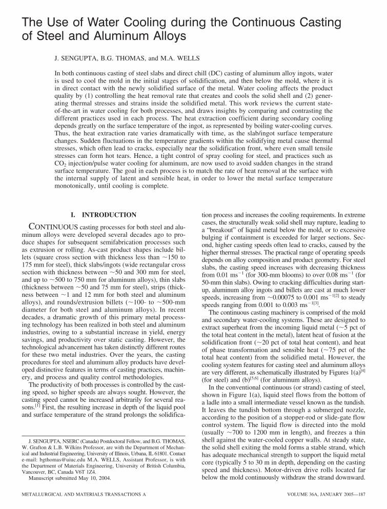
Figure 5[25] illustrates more of the complex phenomena relatedto fluid flow and heat transport inside the mold during the con-tinuous casting of steel The flow pattern and turbulence in thepool is controlled by the nozzle port geometry and submer-gence depth[26] Argon gas is often injected to prevent nozzleclogging[26] and the resulting bubbles provide buoyancy thatgreatly affects the fluid flow pattern These bubbles can alsocollect solid inclusions (such as alumina) which enter the metalpool through the nozzle and get entrapped in the solidifyingshell leading to internal defects in the final product[27] Thejets from the nozzle carry superheat which can sometimes meltthrough locally thin regions in the solidifying shell and causebreakouts[27] The jets also carry significant momentum whichcontrols the flow pattern and affects level fluctuations andmeniscus solidification at the top surface The correspondingflow phenomena during DC casting of aluminum are shownin Figure 6[28] Strong and irregular turbulent flow caused bydirect or oblique entry of metal can create unfavorable (colum-nar) grain structures and uneven distribution of the alloyingelements[28] These problems are overcome by surrounding thenozzle in a distribution bag[29] which diffuses some of the jetmomentum and encourages a slower more stable flow patternthat is also influenced by natural convection
During the continuous casting of steel heat transfer is com-plicated by the presence of mold flux Its source is the moldpowder which is added to the free surface of the liquidsteel to provide thermal and chemical insulation from the atmos-phere and to absorb alumina inclusions The powder sintersand melts spreading over the meniscus and entering the airgap between the steel shell and mold wall[30] Some of the
Fig 5mdashSchematic of phenomena related to heat transfer inside and belowthe mold during continuous casting of steel[25]
Fig 6mdashFlow pattern (left side) and velocities (right side) and dye residence times (lower right) generated with different metal entry systems during DCcasting (a) vertical entry (b) horizontal entry (c) oblique entry and (d) entry through a distribution bag[28]
(a) (b)
(c) (d )
192mdashVOLUME 36A JANUARY 2005 METALLURGICAL AND MATERIALS TRANSACTIONS A
liquid fluxslag resolidifies against the cold mold wall creatinga solid fluxslag rim (refer to Figure 5) Primary cooling atthe meniscus is further complicated by the vertical oscillationof the mold which prevents sticking of the shell to the moldand encourages entrainment of the molten flux into the moldshell interfacial gap[23] However each oscillation cycle cre-ates a transverse depression in the solidifying shell at themeniscus called an oscillation mark shown in Figure 4(a)Pressure from interaction with the flux rim at the meniscuscan deepen these marks[31] according to the size of the rimUnsteady level fluctuations and surface waves due to turbulencecan disturb formation of these marks creating surface defectssuch as ripples or depressions in the final product and arepotential sites for transverse cracks[23] Deep oscillation marksincrease the local gap resistance thereby reducing the heattransfer to the mold and retarding the shell growth[22]
The flux layers between the steel shell and mold wall facil-itate uniform and usually lower heat transfer across the inter-facial gap compared with that of lubricating oil used in billetcasting which tends to produce an intermittent vapor gap Heattransport across the gap naturally depends on the thermalproperties and thickness of the flux layers[19] The gap sizein turn depends on the oscillation mark and surface roughnessprofile shrinkage of the solidifying shell mold distortionand the internal pressure exerted on the shell by the liquidmetal[3233] The gap formed by shrinkage of the shell awayfrom the mold walls is largest where it begins at the cornersand spreads across the faces which further complicates theheat-transfer process[32] The mold walls are routinely taperedto match the steel shrinkage in order to minimize air gap forma-tion and to facilitate primary cooling[34]
It is estimated that primary cooling during continuous cast-ing of steel in the mold removes about 40 pct of the total super-heat and about 30 pct of the total sensible heat[11] The surfaceheat-transfer coefficient typically decreases down the lengthof the mold from a peak value of 1500 to 2000 W m2 K1
at the meniscus to about 600 to 800 W m2 K1[22] near themold bottom Many strand defects such as transverse midfaceand corner cracks can be directly attributed to factors that con-trol primary heat transfer in the mold including oscillationmarks improper mold lubrication metal level fluctuations inthe mold and improper mold taper[3536]
Primary cooling in the mold accounts for only about 20 pctof the total heat extracted[37] from the solidifying ingot duringthe DC casting of aluminum alloys but it still has a criticalinfluence on the ingot surface microstructure and roughness[38]
The heat extracted by primary cooling determines the surfacetemperature of the ingot at the point of exit from the mold Thissubsequently influences the mode of boiling water heat trans-fer (filmnucleate boiling) below the mold[39] as discussed later(in Section B) The peak heat-transfer coefficient reported foraluminum contacting a chilled mold ranges from 2000 to 4000W m2 K1[40] By comparison in the air gap the heat-trans-fer coefficient may be as low as 150 W m2 K1[41]
In DC casting the molten aluminum quickly freezes at themeniscus to form a thick solid shell owing to the higher ther-mal conductivity thermal diffusivity and contraction coef-ficient of aluminum relative to steel As mentioned earlierthe low Peacuteclet number in DC casting allows the chill waterbelow the mold to remove heat from aluminum still insidethe mold Combined with the lack of mold taper this causesthe air gap to form very near to the meniscus and to extend
over most of the mold The extent of the solid shell insidethe mold is referred to as the upstream conduction distance(UCD)[3] If the meniscus level inside the mold is too high(refer to Figure 7(a)[42]) the larger UCD and correspondinglonger wider air gap allows nonuniform reheating of the shellsurface to cause surface composition variations due to macro-segregation and even exudation where solute penetratesthrough the local thin regions of the partially solidified shellSubsequent freezing of solute droplets likely caused the lumpsin Figure 4(b) Furthermore local reduction of cooling ratesproduces unfavorable microstructures such as large grainsize and dendrite arm spacing[28]
On the other hand if the meniscus level is too low (referto Figure 7(b)[42]) the smaller UCD can cause the meniscusto freeze As new liquid flows over the frozen meniscus afold is formed and the ingot surface emerging from the moldhas a rippledlapped appearance such as shown in Figure 4(b)These defects can ultimately lead to transverse cracking dur-ing subsequent processing so an optimum UCD is alwaysdesired Mold flux is not needed to protect the top surfacein DC casting because the molten aluminum quickly oxidizesto form a protective layer of alumina Instead lubricating oilis applied to prevent sticking and also to reduce the amountof heat that flows through the mold wall[3] as also done insteel billet casting when surface quality is not a concern[3]
To optimize heat transport inside the mold and also con-trol the meniscus level several strategies have been imple-mented in the aluminum industry In open top molds themetal level is lowered until folding occurs and then increasedslightly[3] Insulating material is placed on hot top moldsand the UCD is allowed to coincide with a fixed point belowthe insulation Surface quality has been reported to improvedramatically[3] A further improvement in controlling themeniscus contact point is achieved by air-assisted hot topmold systems[43] In the electromagnetic casting process[44]
the mold is completely eliminated and electromagnetic forceis applied to support the metallostatic head Lack of contactbetween the mold and metal removes the problem of air gapformation resulting in uniform cast microstructures The
Fig 7mdashEffect of (a) high and (b) low meniscus level on UCD and temperaturecontours in the mold region of DC casting[42]
(a) (b)
METALLURGICAL AND MATERIALS TRANSACTIONS A VOLUME 36A JANUARY 2005mdash193
Fig 8mdashSecondary cooling during continuous casting of steel (a) typicalarrangement of spray nozzles and support rolls[45] (b) schematic of zones[25]and (c) detail of water spray-cooling process[47]
challenge then becomes maintaining stability of the unsup-ported meniscus by careful adjustment of the electromagneticforce to balance surface flows
Another important factor controlling the extent of primarycooling is the effect of the cooling water on temperature anddistortion of the mold itself During the continuous casting ofsteel cooling water flowing through the vertical slots in thecopper mold extract heat from the mold and simultaneouslycontrol its temperature The hot-face temperature of the moldindirectly affects the heat extraction rate by altering the prop-erties of the interfacial gap Mold variables directly control moldtemperature but the effects on primary cooling are more com-plex For example decreasing the velocity of the cooling waterlowers the heat-transfer coefficient at the cold-face wall of themold causing mold temperature to increase[22] Increasing thetemperature of the hot-face wall of the mold may partiallymelt the slag rim leading to increased heat extraction from themold The effect is counterintuitive as primary cooling mightincrease with less cooling water Impurities in the water cancause deposition of scale on the mold wall near the meniscuscausing mold temperature to increase[22] If the cold face tem-perature becomes too high water may locally boil to form astable film of air bubbles on the wall This virtually stops heatremoval and causes the mold to become dangerously hot
The impact of mold cooling water on primary cooling duringthe DC casting of aluminum has not been explored perhapsbecause the mold cooling water also has an even more impor-tant role below the mold Research has mostly focused on thesecondary heat extraction process of direct impingement ofwater on the hot metal surface exiting the mold
B Water (or Secondary) Cooling
After emerging from the mold the continuous-cast strandis cooled by direct contact of water with the hot metal surfaceas shown in Figures 2(a) and (b) This is referred to as secon-dary cooling For steel casting banks of nozzles located bet-ween contact rolls beneath the mold spray water to cool themoving metal strand Usually the spray nozzles are arrangedinto banks or cooling zones assigned to the top and bottomsurfaces of particular strand segments[45] as shown in Fig-ure 8(a) The water is forced under high pressure as dropletsthat form a mist which continuously impact upon the metalsurface Therefore secondary cooling between each pair of rollsinvolves several different heat-transfer mechanisms operatingin different subzones which are illustrated in Figure 8(b)[25]
These are (1) roll contact cooling (2) radiation and air convec-tion from the bare strand surface just in the roll bite just abovethe spray region (3) cooling due to spray water impingementand (4) water convection cooling just below the spray regionwhere water runs down the strand and collects in the roll biteBulging of the steel shell caused by ferrostatic pressure canaffect these heat-transfer subzones especially near the rollbite and if the support rolls are spaced too widely apart[46]
For aluminum casting water jets emerge from holes locatedbelow the water-cooled mold and directly contact the metalsurface as shown in Figure 9(a)[21] These jets form a contin-uous film which wets the vertical ingot surfaces and rollsdownward Referring to Figure 9(a)[21] two distinct subzonescan be distinguished on the ingot surface (a) the water impinge-ment zone where abrupt cooling occurs due to the direct con-tact with water and (b) the streaming zone located below (a)
where the heat flux diminishes as the water film loses momen-tum with increasing distance from the impingement pointThe length of the water impingement zone is usually 10to 15 mm depending on the diameter of water holes at thebase of the mold and angle of impingement
Secondary cooling mechanisms provided by water sprayfor steel and water film for aluminum have distinctly differentcharacteristics[47] as presented in Figures 8(c) and 9(b) Inspray cooling (Figure 8(c)) water droplets impinge onto thevery hot steel surface and vaporize instantaneously to create
Fig 9mdash(a) Secondary cooling regimes during DC casting of aluminum[21]
(b) Detail of water film cooling process[47]
(a) (c)
(b)
(a) (b)
194mdashVOLUME 36A JANUARY 2005 METALLURGICAL AND MATERIALS TRANSACTIONS A
Fig 10mdashGeneric boiling curve for water cooling indicating the different heat-transfer regimes[49]
a boundary layer which prevents the water from wetting thesurface Heat extraction is higher toward the center of theimpingement region where more of the high-speed dropletshave enough momentum to penetrate the vapor layer Extremelyirregular flow conditions develop within the vapor boundarylayer and it eventually becomes wavy and is thinned out Theshort contact times between the spray droplets and the strandsurface increase with water velocity owing to increased watermomentum Thus the secondary cooling rate increases greatlywith spray water flow rate although it is almost independentof strand surface temperature In contrast under film coolingconditions (Figure 9(b)) water flows along the surface at auniform velocity As a result the boundary layer of vapor bet-ween the water film and the metal surface tends to be thickerand unperturbed However as the metal surface cools thevapor layer breaks down and the water film starts to contactthe strand surface The area of contact increases with decreas-ing strand surface temperature and is accompanied by a suddenincrease in heat transfer The cooling process is transient andis difficult to control
In the continuous casting of steel the purpose of secondarycooling is to maintain the heat extraction and solidificationinitiated in the mold with minimal change in surface temper-ature in order to avoid generating tensile stresses large enoughto cause cracking Only about 50 to 60 pct of the total heatcontent (including superheat latent heat and sensible heat) isremoved by secondary cooling[48] However this heat-transferprocess is critical in DC casting as the chill water extracts about80 pct of the total heat content during the steady-state regimebelow the mold (the term ldquosecondaryrdquo appears to be misplacedfor the DC casting process while referring to cooling by chillwater that originates in the mold)
The extraction of heat by cooling water is quite complexfor both water spray and film cooling conditions because itis governed by the water boiling water phenomena[49] whichdepends greatly on temperature As shown in Figure 10 fourmechanisms of heat transfer[49] can be distinguished whencooling water comes in contact with a hot metal surface Inorder of increasing surface temperature they are as follows
1 Convective cooling at temperatures lower than 100 degCIn this regime heat transfer occurs via natural convection
currents in the water film adhering to the metal surface andthe heat-transfer coefficient is very low
2 Nucleate boiling between 100 degC and burnouttemperature
As the surface temperature increases bubbles of watervapor form on the metal surface break off and flow in thewater film eventually escaping from the free surface The inten-sity of bubble formation and breakaway continues to increaseas the surface temperature rises This effect encourages goodcirculation in the water film causing the heat-transfer coef-ficient to increase rapidly until it reaches a maximum (referredto as the burnout point) The burnout temperature is about500 degC to 700 degC for steel and 200 degC for aluminum andincreases with increasing water flow rate
3 Transition boiling between burnout and Leidenfrosttemperatures
Beyond the burnout point the bubbles start sticking to themetal surface and a layer of vapor begins to form which cutsdown the circulation of heat The heat-transfer coefficientdecreases sharply with increasing temperature as the vaporfilm continues to cover more of the metal surface with ever-decreasing amounts of metal surface exposed directly to waterWhen the metal surface is fully covered by a stable vapor filmthe heat-transfer coefficient associated with the boiling curvereaches a minimum which is referred to as the Leidenfrostpoint The Leidenfrost temperature is about 700 degC to 1000 degCfor steel and 300 degC to 500 degC for aluminum
4 Film boiling at high temperatures (Leidenfrosttemperature)
At temperatures above the Leidenfrost point heat is trans-ferred by conduction through the stable vapor film The heat-transfer coefficient does not change much with temperatureand is very low compared to that at the burnout point
Two important points characterize the boiling curve in Fig-ure 10 They are (1) the burnout temperature which indicatesthe maximum heat flux (and heat-transfer coefficient) anddetermines the maximum ability of the water film to coolthe metal surface by nucleatetransition boiling and (2) theLeidenfrost temperature which indicates the change in heat-transfer mode from transition to vapor film boiling Due to thestrong corelationship between the heat-transfer coefficient andthe surface temperature heat extraction rates by secondarycooling can change rapidly with time and location near theLeidenfrost temperature High heat-transfer rates associatedwith nucleate boiling can cause surface temperature to decreaserapidly In contrast the low heat-transfer rates associated withfilm boiling can allow surface temperature to increase As aresult abrupt changes in the metal surface temperature canoccur as the boiling phenomena are shifted from nucleateto film boiling and vice versa depending on whether theLeidenfrost temperature is exceeded Also extreme variationsof cooling can occur simultaneously at different locations onthe metal surface depending upon the local boiling behavior
To optimize secondary cooling the heat-transfer rate fromthe metal surface should produce a stable surface temperaturethat decreases monotonically Film boiling is deliberately pro-moted during the secondary cooling process for the continuouscasting of steel in order to avoid the unstable surface temper-atures and heat extraction rates that accompany nucleatetran-sition boiling if the steel surface temperature drops too lowHowever during the DC casting process nucleate boiling isdesired on the ingot surfaces during secondary cooling in order
METALLURGICAL AND MATERIALS TRANSACTIONS A VOLUME 36A JANUARY 2005mdash195
Fig 11mdashDifferent boiling phenomena observed on DC cast ingot rollingsurface during startup showing the evolution of the semielliptical-steambarrier region of film boiling in the hotter bottom-center region of the ingotsurface which collapses with time[5051]
to achieve high enough heat extraction rates under steady-stateoperations
During startup of DC casting it is a common industry prac-tice to deliberately maintain a lower water flow rate in orderto keep the ingot relatively hot for long enough to avoid intensecooling and stress buildup This complicates the secondary cool-ing as a portion of the water curtain may be ejected away fromthe ingot surface due to the formation of a stable film boilinglayer beneath it The heat-transfer rate is significantly lowerwithin the region of water ejection as there is little or no con-tact of the water film with the ingot surface The result is aregion with greatly reduced cooling at the hottest portion of theingot surface below the impingement zone As the ingot sur-face cools however the film boiling switches to transitionand then to nucleate boiling The water curtain is able to travelfurther down the ingot surface before it is ejected Eventuallythe surface is no longer hot enough to sustain film boiling thestable film layer region collapses and the cooling rate increasesThe entire surface then has a stable water curtain with nucle-ate boiling heat transfer This process is illustrated schemati-cally in Figure 11[5051] The film boiling area appears as a vis-ible ldquodomerdquo on the ingot surfaces with a parabola-shaped steambarrier profile demarcating the nucleatetransition and film boil-ing heat-transfer zones This visual manifestation of water ejec-tion which is observed on the ingot vertical faces during thestart-up phase is illustrated in Figure 11(a)[51]
The various heat-transfer mechanisms associated withsecondary cooling during continuous casting of both steel andaluminum are important because they determine the tem-perature gradients that develop inside the solidifying strandThus they significantly influence the development of inter-nal thermal stressstrain below the mold and can aggravatedefects generated inside the mold or introduce new defects
Quality problems related to secondary cooling will be dis-cussed in Section III
C Radiative Cooling during Continuous Casting of Steel
Beyond the spray zone region the heat-transfer processsimplifies to radiation and natural convection The smallercooling rate of radiative cooling results in reheating of thesolidified strand which causes the strand surface to expandIf the surface reheats too much before complete solidificationthen plastic deformation of the hot austenitic shell and semi-solid core may not be able to accommodate this expansionThis may cause subsurface hot-tear cracks to form at the solid-ification front[15] These cracks can cause internal segregationdefects or they may propagate through to the surface duringlater processing such as rolling
D Ingot Base Cooling during the DC Casting of AluminumAlloys
Secondary cooling also plays an important role in coolingthe ingot base during the beginning of the start-up phase ofthe DC casting process As the liquid metal enters the bottomblock the initial rate of heat transfer from the molten metalto the cold bottom block is extremely high After a very shorttime a small gap at the interface forms due to solidificationshrinkage and the rate of heat-transfer drops This gap remainsrelatively small until the ingot begins to withdraw from themold and the base experiences a large macroscopic thermaldistortion called butt curl This is aggravated by the slowcooling of the base owing to the large gap and lack of watercombined with high thermal contraction of the vertical sidesof the ingot which experience higher heat extraction fromthe direct contact of a stable curtain As the base continuesto deform (or curl) water flowing down the sides may enterthe bottom gap (water incursion) and enhance the heat transferfrom the ingot base[5253] This in turn will influence furtherdeformation of the base The details of the important interfacialheat-transfer processes active near the base of the ingot areschematically shown in Figure 12[5]
Fig 12mdashCooling and deformation of ingot base during the startup of DCcasting showing high contact near the center of the ingot (region A) andentry of secondary cooling water near the outer edges (region B)[5]
196mdashVOLUME 36A JANUARY 2005 METALLURGICAL AND MATERIALS TRANSACTIONS A
Fig 13mdashTypical surface temperature profile and cooling regimes alongstrand length during continuous casting of (a) steel[25] and (b) aluminum[5]
(a)
(b)
E Strand Cooling Behavior
Figures 13(a)[25] and (b)[5] compare typical surface tempera-ture profiles along the strand length observed during the contin-uous casting of steel and aluminum alloys respectivelyFigure 13(b) also compares two aluminum ingots producedby DC casting at different cooling rates (lower water flow rateswere used for the hot cast) The primary and secondary coolingheat-transfer regimes can be easily identified in the coolingcurves of both processes (refer to the cold cast in Figure 13(b))
For steel the extent of primary cooling is important as itresults in a temperature drop of 250 degC whereas for alu-minum the initial drop in the mold is 100 degC This is fol-lowed by reheating caused by the long air gap Below the moldthe temperature during the continuous casting of steel variesover 100 degC over each roll pitch as shown in Figure 13(a)Near the top of the caster the greatest surface temperaturedrop occurs beneath each spray jet while a tiny dip occurs ateach small region of direct contact with a contact roll Lowerin the caster the growing ferrostatic pressure increases thelocal heat extraction during roll contact which makes the rela-tive size of the spray and roll-contact dips become closer
In contrast during the DC casting process Figure 13(b)shows that aggressive cooling from direct impingement ofwater at a high flow rate onto the metal surface causes theingot surface to cool monotonically by 450 degC to 500 degCin only 300 mm With less water the hot cast did not achievesufficient cooling at the impingement zone allowing the sur-face temperature of the ingot to exceed the Leidenfrost tempera-ture As a result the heat transfer was in the film boiling range(refer to Figure 10) such that the rate of heat transfer waslow and kept the solidifying shell dangerously hot near thesolidus temperature for a long time This also caused themacrodeformation of the ingot base to decrease from 50 mmfor the cold cast to 6 mm for the hot cast
III QUALITY PROBLEMS RELATEDTO SECONDARY COOLING
One of the most important considerations during the con-tinuous casting process is the capability of attaining a defect-free slab or ingot Two such quality issues are (1) hot tearingand cold cracking and (2) dimensional control (eg bulgingof the steel shell and butt curl for aluminum ingots) Theseproblems are directly attributed to tensile mechanical andthermal stressesstrains generated during the casting processThe variety of crack defects that affect continuous cast steelslabs and DC cast aluminum ingots are shown schematicallyin Figures 14[54] and 15[55] respectively
Fig 14mdashSchematic of crack defects in continuous casting of steel[54]
Fig 15mdashSchematic of cold crack defects related to secondary cooling dur-ing DC casting of aluminum[55]
METALLURGICAL AND MATERIALS TRANSACTIONS A VOLUME 36A JANUARY 2005mdash197
Mechanically generated tensile strains such as caused byinadequate mold lubrication or bendingstraightening of thestrand usually act in the longitudinal direction and causetransverse cracking During the casting process rapid coolingcan result in steep temperature gradients in the solidifyingshell that can generate thermal strains as the shell expandsand contracts Sudden localized cooling can introduce tensilestrains at the surface whereas reheating can generate tensilestrains at the solidification front Thermal strains act predom-inantly in the transverse direction and are responsible forcausing longitudinal cracks
Cracks can form if the generated tensile strain locally exceedsthe strain to fracture of the metal In steel different regionsof low ductility have been reported[54] The most importantone lies within 50 degC of the solidus temperature and is respon-sible for ldquohot tearrdquo cracks Aluminum experiences a similarrapid loss in strength and ductility between the solidus tem-perature and the coherency point (ie the temperature corres-ponding to about 90 pct solid fraction)[56] Other mechanismsinvolving sulfide oxide and nitride precipitates at the grainboundaries operate in steel at lower temperatures between700 degC and 900 degC[35 57] and cause intergranular cold cracks
Most cracks in steel slabs and billets are hot tears due tothe zone of low ductility near the liquid front Internal cracksare often seen near the corners at the centerline or diagonallybetween opposite corners Surface cracks can appear near bothmidface and corner regions Some cracks that form below900 degC during the straightening of the shell have been attrib-uted to the embrittlement caused by precipitation of AlN nearthe grain boundaries[57]
In aluminum ingotsbillets hot tears or ldquopresolidificationrdquocracks can also form near the solidification front when a tensilestress is imposed across partially solidified grains and thesurrounding liquid cannot fill the gap between the grainsHence these cracks are always intergranular In contrast coldcracks in aluminum ingots are initiated at temperatures belowthe solidus due to extremely high thermal stresses and arealways transgranular
Brimacombe et al[48] have summarized the causes of crack-ing problems in continuous cast steel Improper secondarycooling practices contribute to many of these Excessive spraycooling or insufficient spray length led to surface reheatingwhich induces tensile stresses beneath the surface includingthe solidification front This can cause internal cracks such asmidway cracks in billet casting Unsymmetrical cooling atthe billet corners induces distortion and diagonal cracks Exces-sive spraying of water can lead to rapid cooling and largetensile strains at the surface of slab castings which can opensmall cracks formed in the mold However insufficient spraycooling below the mold can allow the slab to bulge out if thesurface becomes too hot This can lead to several defects suchas triple point cracks midface cracks midway cracks center-line cracks and center segregation as shown in Figure 14Transverse surface and corner cracks begin in the mold butcan be opened by axial tensile stresses induced by spray cool-ing in slab casting when the surface temperature is withinthe low-ductility range of 700 degC to 900 degC Secondary coolingpractices that lead to excessive surface temperature fluctua-tions also aggravate these cracks especially in this critical tem-perature range
The thermal stresses and strains generated in the ingotduring the transient start-up phase of the DC casting process
can initiate hot tears and cold cracks especially in high-strength aluminum alloys[58] Hot tears generally form bet-ween the quarter points of a rectangular ingot beneath theingot surface As shown in Figure 15[55] cold cracks alsooriginate at the ingot base and are located in the centerhalf of the ingot width High casting speeds tend to causehot tears and low casting speeds increase the risk of coldcracks[3] The formation of hot tears has also been linked withthe frictional forces between the ingot and mold (which isrelated to mold cleanliness)[42] and the variability in coolingconditions during the transient start-up phase[59] In addition tocracks thermal stresses related to secondary cooling alsogenerate macrodeformation of the ingot base or butt curl espe-cially during startup As reported by Droste and Schneider[12]
the production problems related to butt curl include thefollowing runouts of the melt cold shuts reduced rigidstanding (instability) of the ingot on the bottom block andlow recovery rates Ultimately if the magnitude of butt curl isexcessive the ingot bottom may have to be sawed off
IV FUNDAMENTAL INVESTIGATIONS OF WATER-COOLING PROCESSES
A Primary Cooling
Many fundamental experiments have been conducted toquantify convective heat transfer in confined channels andthey are summarized with empirical correlations[6061] Theserelations have been applied to the continuous casting of steelto quantify heat transfer in the mold The heat-transfer coef-ficient between the sides of the water channels in the moldand the cooling water is calculated assuming turbulent flowthrough an equivalent diameter pipe such as described bythe following relationship[60]
[1]
where D is the equivalent diameter of the water channelRewaterf is the Reynolds number at the average of mold coldface and cooling water temperatures Prwaterw is the Prandtlnumber of water at the mold cold face temperature and c1
and c2 are empirical constants Other similar relationshipsare discussed elsewhere[2562]
Increasing the water flow in the mold increases the heat-transfer rate and thereby decreases the mold temperatureleading to less mold distortion and fewer surface cracksAs discussed previously the effect on mold heat flux is indi-rect because mold heat flux is controlled mainly by theinterfacial gap and thickness of the solidifying shell Thisrelationship is well appreciated in the continuous casting ofsteel but has received little attention in DC casting molds
B Secondary Cooling
Experiments have been conducted to quantify heat transferfrom water cooling and to establish boiling water curves(refer to Figure 10) in controlled laboratory experiments onsmall steel[4863ndash68] and aluminum[215069ndash76] samples in plantmeasurements of secondary cooling in the continuous castingof steel[77] and in DC casting of aluminum[78ndash81] Generallyempirical relationships are developed by applying inverseheat-transfer analysis to the measurements recorded by
hw kwater
D c 5 0015Rewaterf
c1 Prwaterwc2 d
198mdashVOLUME 36A JANUARY 2005 METALLURGICAL AND MATERIALS TRANSACTIONS A
Fig 16mdashTypical boiling curves and operating temperature ranges in thesecondary cooling regime for continuous casting of steel[48] and DC cast-ing of aluminum[21]
thermocouples embedded in the plate or casting Figure 16[2148]
compares typical boiling curves for steel and aluminum alloysobtained from such laboratory studies Although the basicfeatures of the boiling curves for the two systems are thesame the magnitude of maximum heat flux and Leidenfrosttemperatures will differ due to the differences in thermophys-ical properties[47] of the two metals as well as surface effectssuch as oxide layers and surface roughness A heat inputfactor can be used to characterize heat transport tothe metalwater interface This factor is 15 times greaterfor aluminum than for steel indicating that heat flux canreach the interface more easily for aluminum than for steel
Studies on secondary cooling and the boiling water curvefor the continuous casting of steel reveal the followingobservations
(1) Typical values of the maximum heat-transfer coefficientmeasured by different researchers[656777] lie between 20 and30 kW m2 K1 at the burnout temperature of 500 degCto 700 degC
(2) Within the desired surface temperature range of 900 degCto 1200 degC for spray cooling the surface temperatureof the strand has little impact on the spray heat-trans-fer coefficient This relative lack of dependence clearlyindicates that the heat-transfer mechanism is dominatedby the convective heat transport occurring between thesurface of the casting and a stable film of steam adher-ing to it (film boiling)
(3) Within the film boiling regime the spray heat-transfer coef-ficient has a strong correlation with the water flow rate asrepresented by the following empirical relationship[67]
[2]
where hspray is the spray heat-transfer coefficient (in W m2
K1) A and c are fitting parameters and is the waterflow rate (in L m2 s1) Typically A is 045 to 075 andc is 05 to 10[48]
(4) Increasing the discharge velocity of the spray dropletsincreases their momentum to break through the vaporlayer which suppresses stable film boiling and thusincreases the heat-transfer rate[65]
W
hspray AW c
1krcp
(5) The Leidenfrost temperature is 1000 degC and increasessharply with increasing water flow rate for the same reason
(6) Increasing the temperature of the spray water has littleinfluence on the heat-transfer coefficient although onecorrelation shows a slight decrease[67]
(7) The spray nozzle orientation has a small but importanteffect on the heat-transfer coefficient[65] Specificallyupward spraying is 15 pct less than downward spray-ing The heat-transfer coefficient decreases greatly withdistance from the impingement point As spray nozzlesare oriented perpendicular to the strand surface thisdecrease is roughly symmetrical
From the secondary cooling studies conducted for DCcasting of aluminum alloys the following observations canbe made
(1) There is a general agreement between different measurementtechniques that the maximum heat flux is between 1 and5 M W m2 and the maximum heat-transfer coefficientlies between 40 and 50 kW m2 K1 The correspondingburnout temperature is 200 degC to 250 degC
(2) Fundamentally the operating temperature range of 220 degCto 620 degC is wider than for steel casting extending downto the burnout temperature so the ingot surfacetemperature has more effect on the heat transfer
(3) The Leidenfrost temperature is 250 degC to 350 degC andincreases with increasing water flow rate in the same wayas observed for steel The heat-transfer coefficient at theLeidenfrost temperature is very sensitive to water flowrate at low flow rates Thus the water flow rate deter-mines whether stable film boiling or water ejection willoccur during the startup of DC casting The Leidenfrosttemperature can also be influenced by the water qualityas well as the water temperature[72]
(4) The oblique orientation of the water nozzle used in DCcasting greatly affects the heat transfer Because flow isdirected downward along the ingot surface the heat fluxvaries greatly with distance above or below its maxi-mum at the impingement point It drops significantlyin the region of back flow above the impingement pointIt decreases only gradually with distance below theimpingement point as the water film loses momentumand can be ejected from the surface by the formationof a stable vapor barrier
(5) The rate of heat extraction is a strong function of metalsurface temperature This is shown in Figure 17[21] as afunction of temperature at the impingement point and inthe streaming zone This figure shows that the heat fluxalso depends strongly on the initial temperature of thesurface when water is first added which affects the tran-sient coevolution of the water layer and the metal surfacetemperature
(6) Under transient conditions the rate of heat extractionhas also been found to be influenced by alloy thermalconductivity with higher conductivity material producinghigher maximum heat fluxes for a given flow rate andsurface temperature[21]
(7) The morphology of the ingot surface emerging from themold has a significant impact on the boiling curvebehavior with rougher surfaces exhibiting higher heat-transfer rates[21]
METALLURGICAL AND MATERIALS TRANSACTIONS A VOLUME 36A JANUARY 2005mdash199
C Model Applications
The heat-transfer relations obtained from experimentalmeasurements described in Section B allow the study ofthermomechanical behavior in continuous casting processesusing mathematical models These relations can be implemen-ted as Cauchy-type boundary conditions into finite-difference(FD) or finite-element (FE) based computational models todescribe the cooling processes These models can then pre-dict the evolution of temperature shell thickness stress andstrain in the strand as it is cooled first in the mold and thenduring the secondary cooling zones
Predicted results from some of these models are presentedhere to provide further insight into the heat-transfer phenomenaacting during the continuous casting of steel and aluminum Forexample the distribution of heat removed during the contin-uous casting of steel can be calculated from a one-dimensionalFD model CON1D[25] Figure 18 shows the heat removed perunit area of the shell surface at different distances along theprocess Most of the superheat is removed from the moltensteel either inside the mold or near the mold exit The totalheat extracted per unit area of shell surface is similar on thewide and narrow faces However the narrow faces extract alarger fraction of the superheat because the bifurcated nozzlesused in slab casting direct the superheat jets of molten steelonto the narrow faces Secondary cooling is responsible forextracting the latent heat and some of the sensible heat fromthe solidifying shell The latent heat is almost twice as largeas the sensible heat extracted Similar trends can be expectedin the case of DC casting of aluminum
The shell thickness predictions from a 2-D[46] and a 3-D[2]
FE-based thermal model for casting steel and aluminum areshown in Figures 19 and 20 respectively Profiles at the moldexit and in the secondary cooling are compared Temperature
Fig 17mdashEffect of initial sample temperature on calculated boiling curves[21]
(as-cast AA5182 water flow rate 038 L s1) for (a) the impingementzone and (b) the streaming zone
(a)
(b)
Fig 18mdashDistribution of total heat removed from the shell at different locationsduring the continuous casting of steel[25]
Fig 19mdashTemperature profiles and shell thickness predicted in cross sec-tions through the strand taken at mold exit and during secondary coolingfor continuous casting of steel[46]
200mdashVOLUME 36A JANUARY 2005 METALLURGICAL AND MATERIALS TRANSACTIONS A
Fig 20mdashTemperature profiles and shell thickness predicted in cross sectionsthrough the ingot during secondary cooling taken 375 s after startup forDC casting of aluminum[2]
gradients through the shell are linear at the mold exit Theshell thickness at the mold exit is 20 mm for a typicalcase as shown in Figure 19 and its surface temperaturedrops to 70 pct of the melting (liquidus) temperature Tm inabsolute degrees (K) In contrast Figure 20 shows that dur-ing the DC casting of aluminum the solidifying shell mayexit the short mold relatively hotter at 85 pct of Tm Thismay leave the shell in a mushy state if the solidificationrange of the alloy is large such as 100 degC for an AA5182alloy Shrinkage of the surface caused by subsequent coolingof the mushy shell by chill water can force the exudationof interdendritic liquid droplets and result in a very roughcast surface as shown in Figure 4(b) For an AA1050 alloythe solidification range is 20 degC so the surface appearanceis much smoother
Inside the mold the interfacial gap offers most of the resis-tance to heat extraction However beyond the mold exitthe resistance offered by the thickening shell in the secon-dary cooling zone becomes the rate-limiting factor in theprocess of heat removal from the strand for both continuouscasting processes It is therefore desirable that the secondarycooling process avoids any sudden increase or decrease inthe surface heat extraction rate in order to maintain a lineartemperature gradient and avoid surface temperature variationsthat can generate local thermal strains and cracking problemsFigure 19 shows the predicted temperature distributionsthrough the shell thickness in the secondary cooling regimefor continuous casting of steel between a set of roll pitchesThe steel shell is shown to experience rapid changes in thesurface heat extraction rate while moving beneath the supportrolls as it travels between regions of intense and less-intensespray cooling This greatly changes the thermal fields close(10 mm) to the surface
Intensifying the spray cooling does not improve the rateof solidification as indicated in Figure 19 by the almostunchanged linear temperature gradients deep inside the shellIt does however cause surface temperature variations thatgenerate high local thermal strains near the shell surface thatcan aggravate cracking problems Sharp drops in surfacetemperature can generate surface cracks while the subsequentsharp increases can extend sub-surface cracks Thermal cyclingnear the surface around the Ar3 temperature of steel is par-
ticularly dangerous because it encourages precipitation ofdetrimental phases such as AlN and large internal stresses dueto volume changes associated with the austenite-to-ferritephase transformation
During the start-up phase of the DC casting process thealuminum shell reheats below the mold as seen in Figure 20This indicates the presence of a stable film boiling front onthe rolling face which reduces the heat-transfer coefficientand delays solidification This effect is clearly indicated inFigure 21 which shows temperature contours predicted[2582]
along the vertical faces of the ingot during the startup Asteam barrier exists on the vertical faces 20 mm below themold exit owing to the ejection of water film (accompaniedby generation of steam) from the ingot surface and along thebarrier where the temperature is greater than the Leidenfrosttemperature This profile quantifies the schematic in Fig-ure 11(a) and shows how the centers of the rolling and narrowfaces of the ingot remain at a high temperature for a longerperiod of time than the ingot corners This creates hot spotswith high tensile strains just beneath the shell surface at thecenter of the vertical faces which explains the initiation ofhot tears that have been observed at this location These obser-vations underline the necessity for optimal design of the sec-ondary cooling processes during the continuous casting of bothsteel and aluminum alloys which ensure monotonic coolingof the shell and avoid the initiation and propagation of crackdefects
V OPTIMIZATION OF WATER COOLING
From the previous discussion it is evident that water cool-ing plays a critical role during the continuous casting of steeland the start-up phase of the DC casting process for alumi-num alloys Hence optimizing the parameters that controlthe cooling process is necessary to generate defect-free castingsMold geometry and operating variables can be designed tocontrol the hot face temperature of the mold at the meniscusin order to control primary cooling of the shell The waterchannels in steel continuous casting molds are routinelyconfigured to optimize heat transfer between the coolingwater and mold faces For example reducing the channel
Fig 21mdashSurface temperature contours on the narrow and rolling faces ofa DC cast aluminum ingot at 375 s after startup[2582]
METALLURGICAL AND MATERIALS TRANSACTIONS A VOLUME 36A JANUARY 2005mdash201
depth increasing the spacing and decreasing the width of thewater channels leads to higher hot face temperatures[22] Hotface temperature also decreases with higher water velocitySome operations adjust water velocity online in order to con-trol mold hot-face temperature
The task of optimizing secondary cooling is easier forsteel continuous casting than for DC casting because coolingis governed by film boiling phenomena so the heat-transfercoefficient is relatively independent of the strand surfacetemperature Relationships describing the variation of heatflux with nozzle type nozzle-to-nozzle spacing spray waterflow rate and distance of the spray nozzles from the strandsurface are given in the literature[48657783ndash85] Under steady-state conditions spray practices can be designed to achievecooling conditions that prevent defects Specific techniquesinclude ldquoplateau coolingrdquo[68] and air-water mist cooling[8687]The purpose of plateau cooling is to keep the surface temper-ature of the strand in the spray-cooling zone always above700 degC and to avoid reheating from below this temperatureThis procedure can prevent cracks which are associated withthe loss of ductility in steel at temperatures between 700 degCand 900 degC Air-water mist cooling has helped to providemore uniform cooling in both casting and transverse directionsand hence avoids cracks by minimizing the localized tem-perature fluctuations caused by the undercooling and over-cooling associated with water droplet spray jets Furthermoreautomatic control systems are available in the industry[4588]
to adjust the sprays according to changes in casting speedand thereby optimize secondary cooling conditions for tran-sient conditions as well These control systems make use ofonline computational models to ensure that each portion ofthe shell experiences the same cooling conditions
Unfortunately in DC casting relatively little fundamentalwork has been done to optimize the water-cooling phenomenato control the final ingot quality Despite increased automationthe control of cooling conditions is difficult due to the manycomplex inter-related effects The mold chill water and bot-tom block simultaneously cool the ingot surfaces This com-bined interplay determines the surface temperature of theingot exiting the mold which in turn governs the boilingwater-cooling conditions (filmnucleate boiling) that dictatesecondary cooling Recent practices have focused on varyingbottom block shape and filling rate casting speed and waterflow conditions in order to lower the cooling intensity duringstartup of DC casting which lowers thermal stress and theaccompanying butt curl Combining low cooling water volumewith high casting speed during startup reduces base defor-mation for some alloys[12] Inflatable ingot wipers have alsobeen used to remove cooling water from the ingot surfaceand thus decrease the secondary cooling[89] If carried toofar however these practices can cause excessively high localsurface temperatures that can lead to cracks and breakoutsButt curl can also be reduced by solidifying a thick bottomshell which bends to a lesser extent upon direct impingementof water This can be achieved by appropriate bottom blockdesign[90] or by using longer filling times[91] Additional state-of-the-art water-cooling systems include Alcoarsquos CO2 injec-tion[92] Wagstaffrsquos Turbo process[93] and Alcanrsquos PulseWater technique[94] Both Alcoa and Wagstaff techniques usegases to promote film boiling The gas bubbles in the waterfilm quickly adhere to the ingot surface generating an insu-lating layer that reduces the heat-transfer coefficient The
Alcan process applies rotary valves to turn the cooling wateron and off during the start-up phase Thus the average heatflux is lowered and the surface temperature of the ingotbecomes high enough to trigger film boiling
With the development of sophisticated commercial FEcodes and more powerful computers mathematical modelsbased on fundamental principles can be developed to predictthe temperature distribution and stressstrain fields in thesolidifying strand during the continuous casting process Thisapproach can minimize the immense experimental efforts tra-ditionally required to optimize the process To achieve thisit is critical that these mathematical tools capture all of thecomplexity of the physical phenomena active during the indus-trial process Such models validated by industrial measurementcan prove to be powerful tools for process optimization Alsothese thermal models coupled with a stress model and an appro-priate hot tearingcracking criterion can be effectively usedto develop permissible process windows for casting defect-free products
Over the past several decades mathematical modeling hasbeen extensively used in the steel industry to control both pri-mary and secondary cooling processes Models such as CASIMDYNCOOL and DYSCOS have been adopted by the indus-try for online process control[45] The University of Illinois atUrbanandashChampaign (CON1D[25]CON2D[95]) and LrsquoEcole desMines de Paris[96] have developed FE-based programs to studythe fundamentals of the complex but industrially-relevant phe-nomena in the mold and spray-cooling regimes
Thermomechanical modeling tools to design and optimizethe DC casting process have been developed at several industryand university consortia (such as VirCAST[97] and EMPACT[37]
in Europe and SECAT[98] in the United States) using FEpackages such as MARC[99] (at CORUS Netherlands andPeacutechiney France[37]) ABAQUS[100] (at EPFL-LausanneSwitzerland[1444]) and ALSIM[101]ALSPEN[102103] (at Institutefor Energy Technology and Hydro Aluminum Norway[104])National laboratories in the United States (Albany ResearchCenter Oregon Argonne National Laboratory Illinois andOak Ridge National Laboratory Tennessee) and at the Uni-versity of Kentucky (Lexington KY) have also collaboratedrecently to develop mathematical models to study ingot stresscrack formation and butt deformation[105] and to reduce alu-minum ingot scrap In Canada University of British Columbiaand Alcan International Ltd are also jointly pursuing mod-eling activities to generate hot tearing criteria for the DCcasting process[5]
VI SUMMARY AND CONCLUSIONS
Continuous casting processes for steel and aluminum alloyshave different process design and operating parametersowing to their differences in thermophysical properties suchas melting point thermal conductivity thermal contractioncoefficient and solidification shrinkage However the fun-damental heat-transfer processes characterizing the removalof superheat latent heat and sensible heat are similar Bothmold and water play significant roles in dictating the com-plex cooling phenomena under both transient and steady-state conditions
This article shows how water cooling governs the temper-ature of the metal strand and how asymmetrical or localized
202mdashVOLUME 36A JANUARY 2005 METALLURGICAL AND MATERIALS TRANSACTIONS A
cooling problems can cause defects leading to high rejec-tion rates and low productivity Specific observations includethe following
1 Empirical relations to describe cooling in the water chan-nels are well established and used to optimize primarycooling in the mold during the continuous casting of steelHot face temperature influences interfacial heat transportat the meniscus which greatly affects surface qualityPerhaps the optimization of mold water cooling and therelated control of mold taper and mold distortion whichhave been applied so successfully in the steel industrycould also help to improve the DC casting mold for alu-minum and other nonferrous alloys
2 In the case of continuous casting of steel vapor film boil-ing dominates the heat extraction mechanism during spraycooling As a result the boiling water heat-transfer coef-ficient is independent of strand surface temperature andheat extraction is stably controlled by water flow rate Incontrast transitionnucleate boiling often arises during DCcasting to cause aggressive cooling of the ingot surfacesHowever film boiling is desired during the transient caststart-up phase to reduce the effect of butt curl Effectssuch as water ejection and water incursion coupled withthe rapidly changing ingot surface temperature during thetransient phase can significantly complicate the heat-transferprocess As a result the process is extremely difficult tocontrol
3 Empirical relationships describing the variation of boilingwater heat-transfer coefficient with spray nozzle type noz-zle separation distance of the nozzle from the surface ofthe strand and water flow rate have been established forsecondary cooling of steel However the effects of sur-face finish and water qualitycontamination have not beeninvestigated For DC casting of aluminum alloys correla-tions for boiling water curves have been developed mainlyunder steady-state conditions Only a few studies for cer-tain specific aluminum alloys are available which can des-cribe the boiling water heat transfer during the transientphase at which time the heat-transfer coefficient can be astrong function of ingot surface temperature water flowrate distance from the impingement point and the impinge-ment point temperature
4 Secondary cooling should be designed to cool the strandsurface in a controlled monotonic manner in order to avoidsevere temperature gradient fluctuations that cause cracksDevelopments such as plateau cooling air-mist coolingand online process control with mathematical models hashelped to improve secondary cooling in continuous cast-ing of steel A variety of processes have been developedfor DC casting of aluminum
5 Despite decades of plant trials and increased processautomation quality problems related to water coolingsuch as butt curl and hot tear cracks still nag the DC cast-ing industry Different proprietary ldquorecipesrdquo are currentlyused by different aluminum companies to change cast-ing variables as a function of time and alloy duringstartup There is recent recognition of the need for well-validated fundamentally based thermomechanical mathe-matical models of the DC casting process to aid furtherimprovements including the optimization of water-coolingpractices
VII ACKNOWLEDGMENTS
The authors thank the Natural Sciences and EngineeringResearch Council (NSERC) Canada for providing financialsupport for J Sengupta and the Continuous Casting Consor-tium at the University of Illinois at UrbanandashChampaign
LIST OF SYMBOLS
Symbol Description Unit
A fitting parameter mdashheat input coefficient J m2 K1 s05
Bi Biot number mdashc fitting parameter mdashc1 c2 empirical constants mdashcp specific heat J kg1 K1
h convective heat-transfercoefficient W m2 K1
hspray spray water heat-transfercoefficient W m2 K1
hw convective heat-transfercoefficient betweenmold and cooling water W m2 K1
k thermal conductivity W m1 K1
kwater thermal conductivityof water W m1 K1
Pe Peclet number mdashPrwaterw Prandtl number of water
at the mold cold facetemperature mdash
R size of casting mRewaterf Reynolds number at average
of mold cold face andcooling water temperatures mdash
V casting speed ms1
water flow rate L m2 s1
density Kg m3
REFERENCES1 C Li and BG Thomas Proceedings of the Brimacombe Memorial
Symposium Vancouver BC Oct 1ndash4 2000 TMS Warrendale PA2000 pp 595-611
2 J Sengupta S Cockcroft D Maijer M Wells and A Larouche MetallMater Trans B 2004 vol 35B pp 523-40
3 JF Grandfield and PT McGlade Mater Forum 1996 vol 20pp 29-51
4 BG Thomas in The Encyclopedia of Materials Science and TechnologyVolume II eds KHJ Buschow R Cahn M Flemings B IlschnerEJ Kramer S Mahajan (D Apelian subject ed) Elsevier Science LtdOxford UK 2001 pp 1595-1599 online httpwwwelseviercommrwclus15showMainhtt
5 J Sengupta PhD Thesis University of British Columbia Vancouver2002
6 JB Wiskel PhD Thesis University of British Columbia Vancouver1996
7 EK Jensen Light Metals 1980 TMS Warrendale PA 1980 pp 631-428 WKJ Jones D Xu JW Evans and DP Cook Light Metals 1999
TMS Warrendale PA 1999 pp 841-459 JR Davis ASM Specialty Handbook Aluminum and Aluminum Alloys
ASM INTERNATIONAL Materials Park OH 199410 PW Baker and PT McGlade in Light Metals 2001 JL Anjier ed
TMS Warrendale PA 2001 pp 855-6211 X Huang BG Thomas and FM Najjar Metall Mater Trans B
1992 vol 23B pp 339-56
W
1krcp
METALLURGICAL AND MATERIALS TRANSACTIONS A VOLUME 36A JANUARY 2005mdash203
12 W Droste and W Schneider in Light Metals 1991 EL Rooy edTMS Warrendale PA 1991 pp 945-51
13 J Sengupta S Cockcroft D Maijer M Wells and A Larouche JLight Met 2002 vol 2 (3) pp 137-48
14 J-M Drezet and M Rappaz Metall MaterTrans A 1996 vol 27App 3214-24
15 JK Brimacombe IV Samarasekera and JE Lait in Continuous CastingVol II Heat Flow Solidification and Crack Formation Ed JKBrimacombe IV Samarasekera and JE Lait ISS-AIME WarrendalePA1984 pp 1-8
16 SC Flood PA Davidson and S Rogers in Modeling of CastingWelding and Advanced Solidification Processes VII M Cross and J Campbell eds The Minerals Metals and Materials SocietyWarrendale PA 1995 801-10
17 M Zheng and L Katgerman in Proceedings of the 22nd Ris Inter-national Symposium on Materials Science Roskilde Denmark ARDinesen M Eldrup D Juul Jensen and S Linderoth eds 2001 RisInternational Laboratory Denmark pp 455-60
18 M Trovant and S Argyropoulos in Light Metals 1997 R Huglen edTMS Warrendale PA 1997 pp 927-31
19 Y Meng and BG Thomas Metall Mater Trans B 2003 vol 34Bpp 707-25
20 J Birat M Larrecq J Lamant and J Petegnief in Mold Operationfor Quality and Productivity AW Cramb and E Szekeres ed ISSWarrendale PA 1991 pp 3-14
21 MA Wells D Li and SL Cockcroft Metall Mater Trans B 2000vol 32B pp 929-39
22 RB Mahapatra JK Brimacombe and IV Samarasekera MetallMater Trans B 1991 vol 22B pp 875-88
23 BG Thomas D Lui and B Ho in Sensors and Modeling in Mater-ials Processing Techniques and Applications Proceedings of the TMSAnnual Meeting Orlando FL Feb 9ndash13 1997 TMS Warrendale PA1997 pp 117-42
24 IV Samarasekera and JK Brimacombe Can Metall Q 1979 vol 18pp 251-66
25 Y Meng and BG Thomas Metall Mater Trans B 2003 vol 34Bpp 685-705
26 H Bai and BG Thomas Metall Mater Trans B 2001 vol 32Bpp 269-84
27 BG Thomas and SP Vanka NSF Design Service Manufacturingand Industrial Innovation Research Conf Puerto Rico 2002
28 S Engler W Schmitz MS Ji and A Weiss in Proceedings ofSymposium on Advances in Continuous Casting and Research Tech-nology Cairo Egypt 1992 Abington Publishing UK 1992 192-204
29 G Gruen A Buchholz and D Mortensen Light Metals 2000 RDPeterson ed TMS Warrendale PA 2000 pp 573-78
30 BG Thomas A Moitra and R McDavid Iron and Steelmaker (USA)1996 vol 23 (4) pp 57-70
31 MM Wolf BHM 2000 2000 vol 145 (7) pp 270-7532 R Bommaraju JK Brimacombe and IV Samarasekera ISS Trans
1984 pp 95-10533 BG Thomas Iron amp Steelmaker (ISS Trans) vol 16 (12) 1989
53-6634 BG Thomas Metall Mater Trans B 2002 vol 33B pp 795-81235 JK Brimacombe and K Sorimachi Metall Mater Trans B 1977
vol 8B pp 489-50536 JK Brimacombe F Weinberg and EB Hawbolt Metall Mater
Trans B 1979 vol 10B pp 279-9237 JM Drezet A Bughardt HG Fjaer and B Magnin Mater Sci Forum
2000 vol 329ndash330 pp 493-50038 W Schneider and W Reif in Proceedings of Symposium on Advances
in Continuous Casting and Research Technology Cairo Egypt 1992Abington Publishing UK 1992 173-90
39 DC Weckman and P Niessen Metall Mater Trans B 1982 vol 13Bpp 593-602
40 K Ho and RD Pehlke Metall Mater Trans B 1985 vol 16Bpp 585-94
41 Y Nishida W Droste and E Engler Metall Mater Trans B 1989vol 17B pp 833-44
42 AA Nofal in Proceedings of Symposium on Advances in Contin-uous Casting and Research Technology Cairo Egypt 1992 AbingtonPublishing UK 1992 205-18
43 R Mitamura T Ito Y Takahashi and T Hiraoka in Light Metals1998 R Huglen ed TMS Warrendale PA 1978 pp 281-91
44 J-M Drezet PhD Thesis Ecole Polytechnique Federale de LausanneLausanne Switzerland 1996
45 RA Hardin K Liu A Kapoor and C Beckermann Metall MaterTrans B 2003 vol 34B pp 297-306
46 L Yu PhD Thesis University of Illinois UrbanandashChampaign UrbanaIL 1996
47 HM Tansi and GE Totten Proceedings of the 3rd International Con-ference on Quenching and Control of Distortion Prague Czech Repub-lic 1999 50-61
48 JK Brimacombe PK Agarwal S Hibbins B Prabhakar and LABaptista in Continuous Casting Vol II Heat Flow Solidification andCrack Formation JK Brimacombe IV Samarasekera and JE Laiteds ISS-AIME Warrendale PA 1984 pp 109-23
49 LC Burmeister Convective Heat Transfer John Wiley amp Sons IncNew York 1983 pp 567-77
50 A Larouche Y Caron and D Kocaefe in Light Metals 1998 BWelch ed TMS Warrendale PA 1998 pp 1059-64
51 GP Grealy JL Davis EK Jensen PA Tondel and J Moritz in LightMetals 2001 JL Anjier ed TMS Warrendale PA 2001 pp 813-21
52 W Droste J-M Drezet G-U Grun and W Schneider in ContinuousCasting K Ehrke and W Schneider eds Wiley-VCH New YorkNY 2000 pp 177-83
53 J Sengupta D Maijer MA Wells SL Cockcroft and A Larouchein Light Metals 2001 JL Anjier ed TMS Warrendale PA 2001pp 879-85
54 BG Thomas JK Brimacombe and IV Samarasekera Trans IronSteel Soc 1986 vol 7 pp 7-20
55 J Du BS-J Kang K-M Chang and J Harris in Light Metals 1998B Welch ed TMS Warrendale PA 1998 pp 1025-29
56 LJ Colley Masterrsquos Thesis University of British Columbia Vancouver2003
57 JK Brimacombe in Continous Casting Vol II Heat Flow Solidificationand Crack Formation JK Brimacombe IV Samarasekera and JELait eds ISS-AIME Warrendale PA 1984 pp 199-214
58 JE Jacoby 5th Australasian Asian Pacific Conference on AluminumCast House Technology TMS Warrendale PA 1997 245-51
59 JB Wiskel and SL Cockcroft Metall Mater Trans B 1996 vol 27Bpp 129-37
60 CA Sleicher and MW Rousse Int J Heat Mass Transfer 1975vol 18 (5) pp 677-83
61 FW Dittus and LMK Boelter Univ California Public Eng 1930No 2 pp 443-61
62 LC Burmeister Convective Heat Transfer 1st ed John Wiley ampSons New York NY 1983
63 M Mitsutsuka Tetsu-to-Haganeacute 1968 vol 54 pp 1457-7164 M Shimada and M Mitsutsuka Tetsu-to-Haganeacute 1966 vol 52 p 164365 E Mizikar Iron Steel Eng 1970 vol 47 pp 53-6066 R Alberny A Leclerq and J Basilis Circulaire drsquoInformatio-techniques
vol 3 (315) 1973 763-7667 T Nozaki J Matsuno K Murata H Ooi and M Kodama Trans
Iron Steel Inst Jpn 1978 vol 18 pp 330-3868 E Bolle and JC Moureau Int Conf on Heat and Mass Transfer Met-
allurgical Processes (Yugoslavia) McGraw-Hill NY 1979 304-0669 H Kraushaar R Jeschar V Heidt EK Jensen and W Schneider in Light
Metals 1995 J Evans ed TMS Warrendale PA 1995 pp 1055-5970 J Langlais T Bourgeois Y Caron G Beland and D Bernard Light
Metals 1995 J Evans ed TMS Warrendale PA 1995 pp 979-8671 L Maenner B Magnin and Y Caratini Light Metals 1997 R Huglen
ed TMS Warrendale PA 1997 pp 701-0772 A Larouche J Langlais T Bourgeois and A Gendron in Light
Metals 1999 M Bouchard and A Faucher eds TMS WarrendalePA 1999 pp 235-45
73 IJ Opstelten and JM Rabenberg Light Metals 1999 CE Eckert edTMS Warrendale PA 1999 pp 729-35
74 JZ Jr L Katgerman IJ Opstelten and JM Rabenberg in Light Met-als 2001 JL Anjier ed TMS Warrendale PA 2001 pp 873-78
75 D Li MA Wells and G Lockhart in Light Metals 2001 JLAnjier ed TMS Warrendale PA 2001 pp 865-71
76 LI Kiss T Meenken A Charette Y Lefebvre and R Levesque inLight Metals 2002 W Schneider ed TMS Warrendale PA 2002pp 981-85
77 SG Hibbins in Continuous Casting Vol II Heat Flow Solidificationand Crack Formation JK Brimacombe IV Samarasekera and JELait eds ISS-AIME Warrendale PA 1984 pp 139-51
78 JB Wiskel and SL Cockcroft Metall Mater Trans B 1996 vol 27Bpp 119-27
79 JA Bakken and T Bergstrom Light Metals 1986 TMS WarrendalePA 1986 pp 883-89
204mdashVOLUME 36A JANUARY 2005 METALLURGICAL AND MATERIALS TRANSACTIONS A
80 EK Jensen S Johansen T Bergstrom and JA Bakken Light Metals1986 TMS Warrendale PA 1986 pp 891-96
81 Y Watanabe and N Hayashi in Light Metals 1996 W Hale edTMS Warrendale PA 1996 pp 979-84
82 J Sengupta D Maijer MA Wells SL Cockcroft and A Larouchein Light Metals 2003 W Schneider ed TMS Warrendale PA 2003pp 841-47
83 L Bendig M Raudensky and J Horsky in 78th Steel Making Con-ference Proceedings Nashville TN 1995 ISS 1995 391-98
84 M El-Bealy N Leskinen and H Fredriksson Ironmaking and Steel-making 1995 vol 22 (3) pp 246-55
85 LK Chiang in 57th Electric Furnace Conference 1999 PittsburghPA Iron amp Steel Society Warrendale PA 1999 653-70
86 S-M Lee and S-Y Jang Iron Steel Inst Jpn Int (Japan) 1996vol 36 (Supplementary on Science and Technology of Steelmaking)pp 208-10
87 T Kohno T Shima T Kuwabara T Yamamoto M Wake andT Tsuneoka in Continuous Casting Vol II Heat Flow Solidificationand Crack Formation IV Samarasekera JK Brimacombe and JELait eds ISS-AIME Warrendale PA 1984 133-37
88 LA Baptista Masterrsquos Thesis University of British Columbia Vancouver1979
89 JL Dassel and TC Zinniger Light Metals 1982 TMS WarrendalePA 1982 pp 793-801
90 W Schneider and EK Jensen in Light Metals 1990 CM Bickert edTMS Warrendale PA 1990 pp 931-36
91 W Schneider in Light Metals 2002 W Schneider ed TMS WarrendalePA 2002 pp 953-60
92 H Yu Light Metals 1980 TMS Warrendale PA 1980 pp 613-2893 I Wagstaff US Patent No 4693298 198794 NB Bryson ldquoCasting of Aluminum Ingotsrdquo US Patent No 3411079
196995 A Moitra PhD Thesis University of Illinois UrbanandashChampaign
Urbana IL 199396 F Costes A Heinrich and M Bellet in Modeling of Casting Welding
and Advanced Solidification ProcessesmdashX TMS Warrendale PA 2003pp 393-400
97 A Mo M Rappaz and CL Martin Aluminum 2002 vol 78 (10)pp 856-64
98 A Henry Light Met Age 2000 vol 58 (7ndash8) pp 66-6799 MSC-MARC Reference Manuals MSC Software Corporation
Redwood City CA 2003100 ABAQUS Reference Manuals (Version 66) Hibbit Karlson and
Sorensen Inc Providence RI 2003101 A Hakonsen and D Mortensen Modeling of Casting Welding and
Advanced Solidification Processes VII TMS Warrendale PA 1995pp 963-70
102 HG Fjaer and EK Jensen Light Metals 1995 TMS WarrendalePA 1995 pp 951-59
103 HG Fjaer and A Mo Metall Mater Trans B 1990 vol 21Bpp 1049-61
104 HG Fjaer and A Hakonsen Light Metals 1997 TMS Warrendale PA1997 pp 683-90
105 Aluminum Project Fact Sheet Newsletter published by Office ofIndustrial Technologies Energy Efficiency and Renewable EnergyUnited States Department of Energy (DOE) Washington DC 2000

188mdashVOLUME 36A JANUARY 2005 METALLURGICAL AND MATERIALS TRANSACTIONS A
Fig 1mdashSchematic of (a) the continuous casting process for steel slabs andbillets[4] and (b) the DC casting process for aluminum sheet ingots[56]
Many closely spaced support rolls prevent the outwardbulging of the shell due to the ferrostatic pressure arisingfrom the liquid steel core Water sprays emerge from high-pressure nozzles which are interspaced between the supportrolls and cool the strand during the solidification processOther strategically placed rolls bend the shell to follow acurved path and then straighten it flat prior to torch cutoffinto individual slabs This allows fully continuous opera-tion Start up of this process is a relatively rare occurrenceand is achieved by inserting a ldquodummyrdquo bar to plug the moldbottom Thus the first steel cast in a sequence can be rou-tinely downgraded or scrapped for defects without incurringa significant yield loss
The direct chill (DC) casting process for aluminum alloysis shown schematically in Figure 1(b) In contrast to the con-tinuous casting process for steel DC casting is only semicon-tinuous as the strand is withdrawn vertically for a shortlength (10 m) until the process must be stopped andrestarted when the cast ingot reaches the bottom of the castingpit Thus considerable attention must focus on the initialstart-up stage when defects are most likely to be initiatedTo start the process a bottom block is partially inserted intoan open rectangular mold (usually 100 to 150 mm inlength) Superheated liquid aluminum flows through a laun-der down the nozzle spout through a distribution bag andinto the mold at a predetermined time-varying filling rateOnce the molten metal fills the bottom block to a prescribedheight the bottom block and cast ingot are lowered into acasting pit The aluminum ingot is subjected to cooling bythe transfer of heat to the water-cooled aluminum mold overa very short length (70 to 90 mm) and to cooling throughthe contact of chill water with the solid shell after it emergesfrom the mold cavity This water emerges from a series ofholes which surround the mold at its base The definingcharacter of the DC casting process is the extraction ofheat due to this direct impingement of water on the ingotsurface typically more than 80 pct of the total heat isremoved by this method under steady-state conditions[7] Thethermal field in this semicontinuous process can be consid-ered to develop in two distinct stages During the start up orstage I the liquid pool profile and thermal field continuouslyevolve with time Then during the steady state or stage II theliquid pool profile remains essentially constant or ldquofully
developedrdquo relative to the mold (typically 200 to 500 mm indepth depending on the ingot size and alloy composition[38])Steady-state operation is usually achieved within a cast lengthof 05 to 1 m Finally at the end of casting the bottomblock stops and the ingot is removed from the casting pitto cool
Some of the contrasting features between the continuouscasting of steel and DC casting of aluminum alloys can beattributed to the differences between the thermophysical prop-erties of the two metals Referring to Table I[91011] these canbe summarized as follows
(1) The melting temperature of aluminum alloys is signifi-cantly lower than steel As a consequence continuouscasting machines must remove more heat per unit massof steel and operate in a higher temperature environmentthan aluminum alloys
(2) The thermal conductivity of aluminum alloys is an orderof magnitude higher than that of steel Combined with theslower casting speed (10 times slower than steel con-tinuous casting) this causes faster internal heat extractionresulting in the relatively short liquid pool in DC castingof aluminum alloys mentioned earlier To avoid crackingthe solid strand DC-cast ingots must be cast verticallywithout bending This limits the cast length before it mustbe removed from the casting pit and production restartedfor a new ingot In contrast the liquid metal pool duringcontinuous casting of steel extends well below the moldThis results in a strand with a liquid-filled shell structurewhich can be easily bent and straightened to generate acontinuous supply of solidified semifinished product
(3) The thermal diffusivity of liquid aluminum is about 6times higher than that of liquid steel This means that liq-uid aluminum tends to lose its superheat faster than liq-uid steel for a given fluid flow pattern Temperature pro-files in the solid aluminum therefore respond faster tochanges in surface heat removal
(4) The solidification shrinkage experienced by aluminumalloys is almost twice that of steel Therefore higher ther-mal stresses can be generated within the solidificationldquomushyrdquo zone by aluminum alloys making hot tear cracksmore likely especially in alloys with long freezing ranges
(5) The volumetric latent heat of aluminum is substantiallyless making initial solidification at the meniscus muchfaster than in steel
(6) The thermal contraction coefficient of solid aluminum ishigher than in steel During initial solidification the extracontraction of the solid shell causes deeper surface depres-sions resulting in a marked reduction in mold heat flowand surface quality problems Also the larger thermal con-traction during DC casting leads to greater macrodeformationof aluminum ingots One example is the characteristicdeformation of the ingot base called ldquobutt curlrdquo[512] whichdevelops during startup especially when cooling waterreaches the ingot surface within the base region[13] Understeady-state conditions the solidifying ingot contractsespecially towards the face centers To prevent this effectcalled ingot rolling face ldquopull-inrdquo most high-aspect-ratiomolds are designed with convex shape[14]
This article was undertaken to compare and contrast theheat-transfer phenomena in continuous casting of steel and
(a) (b)
METALLURGICAL AND MATERIALS TRANSACTIONS A VOLUME 36A JANUARY 2005mdash189
Table I Thermophysical Properties of Steel and Aluminum[91011]
Thermophysical Properties Liquid Steel Liquid Aluminum Solid Steel Solid Aluminum
Liquidus temperature (degC) 1525 650 mdash mdashDensity (kg m3) 7020 2400 8000 2600Specific heat (Jkg1 K1) 680 1300 690 900Thermal conductivity (W m1 K1) 26 90 29 190Thermal diffusivity (m2 s1) 054 105 29 105 053 105 81 105
Latent heat of fusion (J m3) mdash mdash 218 108 94 108
Solidification shrinkage (pct) mdash mdash 25 65Thermal contraction coefficient (K1) mdash mdash 12 106 24 106
Fig 2mdashSchematic of cooling processes for (a) continuous casting of steel[15]
and (b) DC casting of aluminum[5]
aluminum alloys focusing on water cooling The implicationson quality problems are then discussed Finally optimalpractices for the control of cooling in both processes areevaluated in the light of these fundamentals
II HEAT TRANSFER DURING CONTINUOUSCASTING PROCESSES
Although the continuous casting processes for steel andaluminum have many differences as just introduced there arealso many similarities owing to the same primary goal ofheat extraction from the molten and solidifying metal Thevarious heat-transfer phenomena acting on the surface of thestrand during the continuous casting of steel and DC castingof aluminum alloys are schematically shown in Figures 2(a)[15]
and (b)[5] respectively Both processes involve a complexinterplay of several heat-transfer mechanisms which includeconvection of superheat in the liquid pool due to the momentumof the incoming metal axial advection and conductionthrough the moving solid shell heat conduction from thesolidification front to the colder outside surface of the metaland heat transfer by convection to the mold (referred to asprimary cooling) to the cooling water below the mold(referred to as secondary cooling) and to the bottom block(for DC casting only during startup)
However the relative importance of these heat flow mech-anisms is different as evidenced by comparing the Peacuteclet (Pe)and Biot (Bi) numbers The Peacuteclet number is the ratio ofadvective to conductive heat flow given by Pe cpVRkwhere is density in kg m3 cp is specific heat in J kg1
K1 V is casting speed in ms1 R is size of the casting inmeters and k is thermal conductivity in W m1 K1 The lowtypical Pe range for DC casting of aluminum ie 18 Pe 45 indicates that axial conduction is as strong as advectionThe Biot number is the ratio of convective to conductive heatflow given by Bi hRk where h is the convective heat-transfer coefficient active on the strand surface in W m2 K1and R is the conductive path length in meters The relativelylow value of Bi for DC casting ie 2 Bi 60[3] indicatesthat the convective thermal resistance offered by the moldcoolingwater contact at the ingot surface can greatly affect the heattransfer in the transverse direction
In contrast for continuous casting of steel these numbersare much higher (1000 times for Pe and 10 times forBi) owing to the higher casting speed and lower thermalconductivity This indicates that the conductive componentin the axial direction is negligible compared to the advectivecomponent while the thermal resistance offered by conductionthrough the casting thickness dominates heat transfer in the
transverse direction The Biot and Peacuteclet numbers also indi-cate the behavior of the liquid core depth profile For Bi 10 the liquid pool shape lengthens almost linearly withincreasing Pe and is almost insensitive to surface heat extrac-tion rate[16] This indicates that the pool depth is proportionalto the casting speed and inversely proportional to the metalconductivity as noted earlier The thickness of the semisolid(or mushy) zone and the hot tearing susceptibility are alsosensitive to the Peacuteclet number[17]
The heat-transfer mechanisms discussed previously not onlycontrol the liquid pool shape which has important implicationsfor productivity but also the magnitude of thermal stresses andstrains generated in the strand owing to thermal contraction ofthe metal upon cooling Changes in the temperature gradientacross the solid shell due to an abrupt increase or decrease inthe heat extraction rate causes differential thermal expansionin the solidifying metal and the generation of high thermal stressand strain This can ultimately lead to internal or surface defectswhich can severely compromise the quality of the cast prod-uct Sections A through E discuss the different heat-transferphenomena that occur during continuous casting
A Mold (or Primary) Cooling
Heat is supplied into a water-cooled mold by the contin-uous flow of incoming liquid metal during the continuouscasting process Heat transport in the liquid pool inside the
(a) (b)
190mdashVOLUME 36A JANUARY 2005 METALLURGICAL AND MATERIALS TRANSACTIONS A
in the mold The flow pattern controls stability and oscillationof the meniscus which governs the surface shape includingthe depth of depressions or oscillation marks and associateddefects The flow pattern also governs the removal of superheatinside the shell where the jet impinges against the solidifi-cation front To decrease the friction between the mold andstrand a lubricating medium is often added to the mold whichforms either a vapor or liquid layer which prevents directcontact between the strand and mold walls
Heat transfer at the metalmold interface in continuouscasting is referred to as mold or primary cooling It varieswith time or distance down the mold and can be subdividedinto two regions of behavior[1819] (1) moldmetal direct con-tact and (2) air gap cooling as shown in Figure 3(a) In thebeginning at the meniscus the solidifying metal is in closecontact with the mold and the heat-transfer rate is very highSpecifically peak heat fluxes can exceed 10 MWm2 in steelcontinuous casting[120] and 1 MWm-2 in aluminum DC cast-ing[2] The latter process has smaller values for several rea-sons Firstly the roughness of the cast surface depends onalloy composition as shown in Figure 4 (025 mm for low-and high-carbon steels and 065 mm for peritectic grades)and (005 mm for AA1050 and 045 mm for AA5182 alu-minum alloys)[21] and this will impact the heat flux in themold The DC cast surface likely has thicker oxide layers withdifferent properties which would increase the contact resis-
Fig 3mdashPrimary cooling during continuous casting (a) temperature pro-file across the mold and shell (steel) and thermal resistances[1923] and (b) schematic of zones (aluminum)[18]
(a)
(b)
Fig 4mdashStrand surface morphologies for typical (a) continuous cast steel and (b) DC cast aluminum alloys[21] (casting direction is to the right)
(a) (b)
mold and at the moldmetal interface affects both initialsolidification at the meniscus and growth of the solid shellagainst the mold The liquid metal usually enters the moldcavity through a ceramic entry nozzle The angle and shapeof the nozzle ports control the direction and turbulence ofthe liquid metal jets which in turn control the flow pattern
METALLURGICAL AND MATERIALS TRANSACTIONS A VOLUME 36A JANUARY 2005mdash191
tance of the interfacial gap In addition the aluminum shellconducts heat faster away from the peak heat flux regionwhich is also shorter in length In steel continuous castingthe newly formed shell remains in relatively good contactwith most of the 700-mm-long mold owing to pressure fromthe internal liquid pool pushing the weak shell against themold walls and intentional tapering of the mold walls tomatch the solidification shrinkage In DC casting howeverthe duration of this initial contact stage is quite brief endingwithin 80 mm[2] (depending upon the casting speed alloycomposition and ingot geometry) of mold-metal contact
Stage 1 ends with the formation of a significant air gap betweenthe metal and mold as soon as the solid shell is strong enoughto contract away from the mold faces In steel continuous cast-ing this happens only near the corners In the DC castingprocess shrinkage of the thick shell away from the untaperedmold produces gap formation around the entire perimeter Oncethe gap has formed the heat-transfer rate is greatly reduced
resulting in a reheating effect within the solid shell Withinstage 2 heat is conducted away from the shell via a series ofthermal resistances[23] (1) air gap (2) mold wall and (3) moldcooling water interface which are shown in Figures 3(a)[1923]
and (b)[18] The interfacial gap comprises up to 85 pct of thisresistance[24] and therefore controls the heat transfer inside themold
Figure 5[25] illustrates more of the complex phenomena relatedto fluid flow and heat transport inside the mold during the con-tinuous casting of steel The flow pattern and turbulence in thepool is controlled by the nozzle port geometry and submer-gence depth[26] Argon gas is often injected to prevent nozzleclogging[26] and the resulting bubbles provide buoyancy thatgreatly affects the fluid flow pattern These bubbles can alsocollect solid inclusions (such as alumina) which enter the metalpool through the nozzle and get entrapped in the solidifyingshell leading to internal defects in the final product[27] Thejets from the nozzle carry superheat which can sometimes meltthrough locally thin regions in the solidifying shell and causebreakouts[27] The jets also carry significant momentum whichcontrols the flow pattern and affects level fluctuations andmeniscus solidification at the top surface The correspondingflow phenomena during DC casting of aluminum are shownin Figure 6[28] Strong and irregular turbulent flow caused bydirect or oblique entry of metal can create unfavorable (colum-nar) grain structures and uneven distribution of the alloyingelements[28] These problems are overcome by surrounding thenozzle in a distribution bag[29] which diffuses some of the jetmomentum and encourages a slower more stable flow patternthat is also influenced by natural convection
During the continuous casting of steel heat transfer is com-plicated by the presence of mold flux Its source is the moldpowder which is added to the free surface of the liquidsteel to provide thermal and chemical insulation from the atmos-phere and to absorb alumina inclusions The powder sintersand melts spreading over the meniscus and entering the airgap between the steel shell and mold wall[30] Some of the
Fig 5mdashSchematic of phenomena related to heat transfer inside and belowthe mold during continuous casting of steel[25]
Fig 6mdashFlow pattern (left side) and velocities (right side) and dye residence times (lower right) generated with different metal entry systems during DCcasting (a) vertical entry (b) horizontal entry (c) oblique entry and (d) entry through a distribution bag[28]
(a) (b)
(c) (d )
192mdashVOLUME 36A JANUARY 2005 METALLURGICAL AND MATERIALS TRANSACTIONS A
liquid fluxslag resolidifies against the cold mold wall creatinga solid fluxslag rim (refer to Figure 5) Primary cooling atthe meniscus is further complicated by the vertical oscillationof the mold which prevents sticking of the shell to the moldand encourages entrainment of the molten flux into the moldshell interfacial gap[23] However each oscillation cycle cre-ates a transverse depression in the solidifying shell at themeniscus called an oscillation mark shown in Figure 4(a)Pressure from interaction with the flux rim at the meniscuscan deepen these marks[31] according to the size of the rimUnsteady level fluctuations and surface waves due to turbulencecan disturb formation of these marks creating surface defectssuch as ripples or depressions in the final product and arepotential sites for transverse cracks[23] Deep oscillation marksincrease the local gap resistance thereby reducing the heattransfer to the mold and retarding the shell growth[22]
The flux layers between the steel shell and mold wall facil-itate uniform and usually lower heat transfer across the inter-facial gap compared with that of lubricating oil used in billetcasting which tends to produce an intermittent vapor gap Heattransport across the gap naturally depends on the thermalproperties and thickness of the flux layers[19] The gap sizein turn depends on the oscillation mark and surface roughnessprofile shrinkage of the solidifying shell mold distortionand the internal pressure exerted on the shell by the liquidmetal[3233] The gap formed by shrinkage of the shell awayfrom the mold walls is largest where it begins at the cornersand spreads across the faces which further complicates theheat-transfer process[32] The mold walls are routinely taperedto match the steel shrinkage in order to minimize air gap forma-tion and to facilitate primary cooling[34]
It is estimated that primary cooling during continuous cast-ing of steel in the mold removes about 40 pct of the total super-heat and about 30 pct of the total sensible heat[11] The surfaceheat-transfer coefficient typically decreases down the lengthof the mold from a peak value of 1500 to 2000 W m2 K1
at the meniscus to about 600 to 800 W m2 K1[22] near themold bottom Many strand defects such as transverse midfaceand corner cracks can be directly attributed to factors that con-trol primary heat transfer in the mold including oscillationmarks improper mold lubrication metal level fluctuations inthe mold and improper mold taper[3536]
Primary cooling in the mold accounts for only about 20 pctof the total heat extracted[37] from the solidifying ingot duringthe DC casting of aluminum alloys but it still has a criticalinfluence on the ingot surface microstructure and roughness[38]
The heat extracted by primary cooling determines the surfacetemperature of the ingot at the point of exit from the mold Thissubsequently influences the mode of boiling water heat trans-fer (filmnucleate boiling) below the mold[39] as discussed later(in Section B) The peak heat-transfer coefficient reported foraluminum contacting a chilled mold ranges from 2000 to 4000W m2 K1[40] By comparison in the air gap the heat-trans-fer coefficient may be as low as 150 W m2 K1[41]
In DC casting the molten aluminum quickly freezes at themeniscus to form a thick solid shell owing to the higher ther-mal conductivity thermal diffusivity and contraction coef-ficient of aluminum relative to steel As mentioned earlierthe low Peacuteclet number in DC casting allows the chill waterbelow the mold to remove heat from aluminum still insidethe mold Combined with the lack of mold taper this causesthe air gap to form very near to the meniscus and to extend
over most of the mold The extent of the solid shell insidethe mold is referred to as the upstream conduction distance(UCD)[3] If the meniscus level inside the mold is too high(refer to Figure 7(a)[42]) the larger UCD and correspondinglonger wider air gap allows nonuniform reheating of the shellsurface to cause surface composition variations due to macro-segregation and even exudation where solute penetratesthrough the local thin regions of the partially solidified shellSubsequent freezing of solute droplets likely caused the lumpsin Figure 4(b) Furthermore local reduction of cooling ratesproduces unfavorable microstructures such as large grainsize and dendrite arm spacing[28]
On the other hand if the meniscus level is too low (referto Figure 7(b)[42]) the smaller UCD can cause the meniscusto freeze As new liquid flows over the frozen meniscus afold is formed and the ingot surface emerging from the moldhas a rippledlapped appearance such as shown in Figure 4(b)These defects can ultimately lead to transverse cracking dur-ing subsequent processing so an optimum UCD is alwaysdesired Mold flux is not needed to protect the top surfacein DC casting because the molten aluminum quickly oxidizesto form a protective layer of alumina Instead lubricating oilis applied to prevent sticking and also to reduce the amountof heat that flows through the mold wall[3] as also done insteel billet casting when surface quality is not a concern[3]
To optimize heat transport inside the mold and also con-trol the meniscus level several strategies have been imple-mented in the aluminum industry In open top molds themetal level is lowered until folding occurs and then increasedslightly[3] Insulating material is placed on hot top moldsand the UCD is allowed to coincide with a fixed point belowthe insulation Surface quality has been reported to improvedramatically[3] A further improvement in controlling themeniscus contact point is achieved by air-assisted hot topmold systems[43] In the electromagnetic casting process[44]
the mold is completely eliminated and electromagnetic forceis applied to support the metallostatic head Lack of contactbetween the mold and metal removes the problem of air gapformation resulting in uniform cast microstructures The
Fig 7mdashEffect of (a) high and (b) low meniscus level on UCD and temperaturecontours in the mold region of DC casting[42]
(a) (b)
METALLURGICAL AND MATERIALS TRANSACTIONS A VOLUME 36A JANUARY 2005mdash193
Fig 8mdashSecondary cooling during continuous casting of steel (a) typicalarrangement of spray nozzles and support rolls[45] (b) schematic of zones[25]and (c) detail of water spray-cooling process[47]
challenge then becomes maintaining stability of the unsup-ported meniscus by careful adjustment of the electromagneticforce to balance surface flows
Another important factor controlling the extent of primarycooling is the effect of the cooling water on temperature anddistortion of the mold itself During the continuous casting ofsteel cooling water flowing through the vertical slots in thecopper mold extract heat from the mold and simultaneouslycontrol its temperature The hot-face temperature of the moldindirectly affects the heat extraction rate by altering the prop-erties of the interfacial gap Mold variables directly control moldtemperature but the effects on primary cooling are more com-plex For example decreasing the velocity of the cooling waterlowers the heat-transfer coefficient at the cold-face wall of themold causing mold temperature to increase[22] Increasing thetemperature of the hot-face wall of the mold may partiallymelt the slag rim leading to increased heat extraction from themold The effect is counterintuitive as primary cooling mightincrease with less cooling water Impurities in the water cancause deposition of scale on the mold wall near the meniscuscausing mold temperature to increase[22] If the cold face tem-perature becomes too high water may locally boil to form astable film of air bubbles on the wall This virtually stops heatremoval and causes the mold to become dangerously hot
The impact of mold cooling water on primary cooling duringthe DC casting of aluminum has not been explored perhapsbecause the mold cooling water also has an even more impor-tant role below the mold Research has mostly focused on thesecondary heat extraction process of direct impingement ofwater on the hot metal surface exiting the mold
B Water (or Secondary) Cooling
After emerging from the mold the continuous-cast strandis cooled by direct contact of water with the hot metal surfaceas shown in Figures 2(a) and (b) This is referred to as secon-dary cooling For steel casting banks of nozzles located bet-ween contact rolls beneath the mold spray water to cool themoving metal strand Usually the spray nozzles are arrangedinto banks or cooling zones assigned to the top and bottomsurfaces of particular strand segments[45] as shown in Fig-ure 8(a) The water is forced under high pressure as dropletsthat form a mist which continuously impact upon the metalsurface Therefore secondary cooling between each pair of rollsinvolves several different heat-transfer mechanisms operatingin different subzones which are illustrated in Figure 8(b)[25]
These are (1) roll contact cooling (2) radiation and air convec-tion from the bare strand surface just in the roll bite just abovethe spray region (3) cooling due to spray water impingementand (4) water convection cooling just below the spray regionwhere water runs down the strand and collects in the roll biteBulging of the steel shell caused by ferrostatic pressure canaffect these heat-transfer subzones especially near the rollbite and if the support rolls are spaced too widely apart[46]
For aluminum casting water jets emerge from holes locatedbelow the water-cooled mold and directly contact the metalsurface as shown in Figure 9(a)[21] These jets form a contin-uous film which wets the vertical ingot surfaces and rollsdownward Referring to Figure 9(a)[21] two distinct subzonescan be distinguished on the ingot surface (a) the water impinge-ment zone where abrupt cooling occurs due to the direct con-tact with water and (b) the streaming zone located below (a)
where the heat flux diminishes as the water film loses momen-tum with increasing distance from the impingement pointThe length of the water impingement zone is usually 10to 15 mm depending on the diameter of water holes at thebase of the mold and angle of impingement
Secondary cooling mechanisms provided by water sprayfor steel and water film for aluminum have distinctly differentcharacteristics[47] as presented in Figures 8(c) and 9(b) Inspray cooling (Figure 8(c)) water droplets impinge onto thevery hot steel surface and vaporize instantaneously to create
Fig 9mdash(a) Secondary cooling regimes during DC casting of aluminum[21]
(b) Detail of water film cooling process[47]
(a) (c)
(b)
(a) (b)
194mdashVOLUME 36A JANUARY 2005 METALLURGICAL AND MATERIALS TRANSACTIONS A
Fig 10mdashGeneric boiling curve for water cooling indicating the different heat-transfer regimes[49]
a boundary layer which prevents the water from wetting thesurface Heat extraction is higher toward the center of theimpingement region where more of the high-speed dropletshave enough momentum to penetrate the vapor layer Extremelyirregular flow conditions develop within the vapor boundarylayer and it eventually becomes wavy and is thinned out Theshort contact times between the spray droplets and the strandsurface increase with water velocity owing to increased watermomentum Thus the secondary cooling rate increases greatlywith spray water flow rate although it is almost independentof strand surface temperature In contrast under film coolingconditions (Figure 9(b)) water flows along the surface at auniform velocity As a result the boundary layer of vapor bet-ween the water film and the metal surface tends to be thickerand unperturbed However as the metal surface cools thevapor layer breaks down and the water film starts to contactthe strand surface The area of contact increases with decreas-ing strand surface temperature and is accompanied by a suddenincrease in heat transfer The cooling process is transient andis difficult to control
In the continuous casting of steel the purpose of secondarycooling is to maintain the heat extraction and solidificationinitiated in the mold with minimal change in surface temper-ature in order to avoid generating tensile stresses large enoughto cause cracking Only about 50 to 60 pct of the total heatcontent (including superheat latent heat and sensible heat) isremoved by secondary cooling[48] However this heat-transferprocess is critical in DC casting as the chill water extracts about80 pct of the total heat content during the steady-state regimebelow the mold (the term ldquosecondaryrdquo appears to be misplacedfor the DC casting process while referring to cooling by chillwater that originates in the mold)
The extraction of heat by cooling water is quite complexfor both water spray and film cooling conditions because itis governed by the water boiling water phenomena[49] whichdepends greatly on temperature As shown in Figure 10 fourmechanisms of heat transfer[49] can be distinguished whencooling water comes in contact with a hot metal surface Inorder of increasing surface temperature they are as follows
1 Convective cooling at temperatures lower than 100 degCIn this regime heat transfer occurs via natural convection
currents in the water film adhering to the metal surface andthe heat-transfer coefficient is very low
2 Nucleate boiling between 100 degC and burnouttemperature
As the surface temperature increases bubbles of watervapor form on the metal surface break off and flow in thewater film eventually escaping from the free surface The inten-sity of bubble formation and breakaway continues to increaseas the surface temperature rises This effect encourages goodcirculation in the water film causing the heat-transfer coef-ficient to increase rapidly until it reaches a maximum (referredto as the burnout point) The burnout temperature is about500 degC to 700 degC for steel and 200 degC for aluminum andincreases with increasing water flow rate
3 Transition boiling between burnout and Leidenfrosttemperatures
Beyond the burnout point the bubbles start sticking to themetal surface and a layer of vapor begins to form which cutsdown the circulation of heat The heat-transfer coefficientdecreases sharply with increasing temperature as the vaporfilm continues to cover more of the metal surface with ever-decreasing amounts of metal surface exposed directly to waterWhen the metal surface is fully covered by a stable vapor filmthe heat-transfer coefficient associated with the boiling curvereaches a minimum which is referred to as the Leidenfrostpoint The Leidenfrost temperature is about 700 degC to 1000 degCfor steel and 300 degC to 500 degC for aluminum
4 Film boiling at high temperatures (Leidenfrosttemperature)
At temperatures above the Leidenfrost point heat is trans-ferred by conduction through the stable vapor film The heat-transfer coefficient does not change much with temperatureand is very low compared to that at the burnout point
Two important points characterize the boiling curve in Fig-ure 10 They are (1) the burnout temperature which indicatesthe maximum heat flux (and heat-transfer coefficient) anddetermines the maximum ability of the water film to coolthe metal surface by nucleatetransition boiling and (2) theLeidenfrost temperature which indicates the change in heat-transfer mode from transition to vapor film boiling Due to thestrong corelationship between the heat-transfer coefficient andthe surface temperature heat extraction rates by secondarycooling can change rapidly with time and location near theLeidenfrost temperature High heat-transfer rates associatedwith nucleate boiling can cause surface temperature to decreaserapidly In contrast the low heat-transfer rates associated withfilm boiling can allow surface temperature to increase As aresult abrupt changes in the metal surface temperature canoccur as the boiling phenomena are shifted from nucleateto film boiling and vice versa depending on whether theLeidenfrost temperature is exceeded Also extreme variationsof cooling can occur simultaneously at different locations onthe metal surface depending upon the local boiling behavior
To optimize secondary cooling the heat-transfer rate fromthe metal surface should produce a stable surface temperaturethat decreases monotonically Film boiling is deliberately pro-moted during the secondary cooling process for the continuouscasting of steel in order to avoid the unstable surface temper-atures and heat extraction rates that accompany nucleatetran-sition boiling if the steel surface temperature drops too lowHowever during the DC casting process nucleate boiling isdesired on the ingot surfaces during secondary cooling in order
METALLURGICAL AND MATERIALS TRANSACTIONS A VOLUME 36A JANUARY 2005mdash195
Fig 11mdashDifferent boiling phenomena observed on DC cast ingot rollingsurface during startup showing the evolution of the semielliptical-steambarrier region of film boiling in the hotter bottom-center region of the ingotsurface which collapses with time[5051]
to achieve high enough heat extraction rates under steady-stateoperations
During startup of DC casting it is a common industry prac-tice to deliberately maintain a lower water flow rate in orderto keep the ingot relatively hot for long enough to avoid intensecooling and stress buildup This complicates the secondary cool-ing as a portion of the water curtain may be ejected away fromthe ingot surface due to the formation of a stable film boilinglayer beneath it The heat-transfer rate is significantly lowerwithin the region of water ejection as there is little or no con-tact of the water film with the ingot surface The result is aregion with greatly reduced cooling at the hottest portion of theingot surface below the impingement zone As the ingot sur-face cools however the film boiling switches to transitionand then to nucleate boiling The water curtain is able to travelfurther down the ingot surface before it is ejected Eventuallythe surface is no longer hot enough to sustain film boiling thestable film layer region collapses and the cooling rate increasesThe entire surface then has a stable water curtain with nucle-ate boiling heat transfer This process is illustrated schemati-cally in Figure 11[5051] The film boiling area appears as a vis-ible ldquodomerdquo on the ingot surfaces with a parabola-shaped steambarrier profile demarcating the nucleatetransition and film boil-ing heat-transfer zones This visual manifestation of water ejec-tion which is observed on the ingot vertical faces during thestart-up phase is illustrated in Figure 11(a)[51]
The various heat-transfer mechanisms associated withsecondary cooling during continuous casting of both steel andaluminum are important because they determine the tem-perature gradients that develop inside the solidifying strandThus they significantly influence the development of inter-nal thermal stressstrain below the mold and can aggravatedefects generated inside the mold or introduce new defects
Quality problems related to secondary cooling will be dis-cussed in Section III
C Radiative Cooling during Continuous Casting of Steel
Beyond the spray zone region the heat-transfer processsimplifies to radiation and natural convection The smallercooling rate of radiative cooling results in reheating of thesolidified strand which causes the strand surface to expandIf the surface reheats too much before complete solidificationthen plastic deformation of the hot austenitic shell and semi-solid core may not be able to accommodate this expansionThis may cause subsurface hot-tear cracks to form at the solid-ification front[15] These cracks can cause internal segregationdefects or they may propagate through to the surface duringlater processing such as rolling
D Ingot Base Cooling during the DC Casting of AluminumAlloys
Secondary cooling also plays an important role in coolingthe ingot base during the beginning of the start-up phase ofthe DC casting process As the liquid metal enters the bottomblock the initial rate of heat transfer from the molten metalto the cold bottom block is extremely high After a very shorttime a small gap at the interface forms due to solidificationshrinkage and the rate of heat-transfer drops This gap remainsrelatively small until the ingot begins to withdraw from themold and the base experiences a large macroscopic thermaldistortion called butt curl This is aggravated by the slowcooling of the base owing to the large gap and lack of watercombined with high thermal contraction of the vertical sidesof the ingot which experience higher heat extraction fromthe direct contact of a stable curtain As the base continuesto deform (or curl) water flowing down the sides may enterthe bottom gap (water incursion) and enhance the heat transferfrom the ingot base[5253] This in turn will influence furtherdeformation of the base The details of the important interfacialheat-transfer processes active near the base of the ingot areschematically shown in Figure 12[5]
Fig 12mdashCooling and deformation of ingot base during the startup of DCcasting showing high contact near the center of the ingot (region A) andentry of secondary cooling water near the outer edges (region B)[5]
196mdashVOLUME 36A JANUARY 2005 METALLURGICAL AND MATERIALS TRANSACTIONS A
Fig 13mdashTypical surface temperature profile and cooling regimes alongstrand length during continuous casting of (a) steel[25] and (b) aluminum[5]
(a)
(b)
E Strand Cooling Behavior
Figures 13(a)[25] and (b)[5] compare typical surface tempera-ture profiles along the strand length observed during the contin-uous casting of steel and aluminum alloys respectivelyFigure 13(b) also compares two aluminum ingots producedby DC casting at different cooling rates (lower water flow rateswere used for the hot cast) The primary and secondary coolingheat-transfer regimes can be easily identified in the coolingcurves of both processes (refer to the cold cast in Figure 13(b))
For steel the extent of primary cooling is important as itresults in a temperature drop of 250 degC whereas for alu-minum the initial drop in the mold is 100 degC This is fol-lowed by reheating caused by the long air gap Below the moldthe temperature during the continuous casting of steel variesover 100 degC over each roll pitch as shown in Figure 13(a)Near the top of the caster the greatest surface temperaturedrop occurs beneath each spray jet while a tiny dip occurs ateach small region of direct contact with a contact roll Lowerin the caster the growing ferrostatic pressure increases thelocal heat extraction during roll contact which makes the rela-tive size of the spray and roll-contact dips become closer
In contrast during the DC casting process Figure 13(b)shows that aggressive cooling from direct impingement ofwater at a high flow rate onto the metal surface causes theingot surface to cool monotonically by 450 degC to 500 degCin only 300 mm With less water the hot cast did not achievesufficient cooling at the impingement zone allowing the sur-face temperature of the ingot to exceed the Leidenfrost tempera-ture As a result the heat transfer was in the film boiling range(refer to Figure 10) such that the rate of heat transfer waslow and kept the solidifying shell dangerously hot near thesolidus temperature for a long time This also caused themacrodeformation of the ingot base to decrease from 50 mmfor the cold cast to 6 mm for the hot cast
III QUALITY PROBLEMS RELATEDTO SECONDARY COOLING
One of the most important considerations during the con-tinuous casting process is the capability of attaining a defect-free slab or ingot Two such quality issues are (1) hot tearingand cold cracking and (2) dimensional control (eg bulgingof the steel shell and butt curl for aluminum ingots) Theseproblems are directly attributed to tensile mechanical andthermal stressesstrains generated during the casting processThe variety of crack defects that affect continuous cast steelslabs and DC cast aluminum ingots are shown schematicallyin Figures 14[54] and 15[55] respectively
Fig 14mdashSchematic of crack defects in continuous casting of steel[54]
Fig 15mdashSchematic of cold crack defects related to secondary cooling dur-ing DC casting of aluminum[55]
METALLURGICAL AND MATERIALS TRANSACTIONS A VOLUME 36A JANUARY 2005mdash197
Mechanically generated tensile strains such as caused byinadequate mold lubrication or bendingstraightening of thestrand usually act in the longitudinal direction and causetransverse cracking During the casting process rapid coolingcan result in steep temperature gradients in the solidifyingshell that can generate thermal strains as the shell expandsand contracts Sudden localized cooling can introduce tensilestrains at the surface whereas reheating can generate tensilestrains at the solidification front Thermal strains act predom-inantly in the transverse direction and are responsible forcausing longitudinal cracks
Cracks can form if the generated tensile strain locally exceedsthe strain to fracture of the metal In steel different regionsof low ductility have been reported[54] The most importantone lies within 50 degC of the solidus temperature and is respon-sible for ldquohot tearrdquo cracks Aluminum experiences a similarrapid loss in strength and ductility between the solidus tem-perature and the coherency point (ie the temperature corres-ponding to about 90 pct solid fraction)[56] Other mechanismsinvolving sulfide oxide and nitride precipitates at the grainboundaries operate in steel at lower temperatures between700 degC and 900 degC[35 57] and cause intergranular cold cracks
Most cracks in steel slabs and billets are hot tears due tothe zone of low ductility near the liquid front Internal cracksare often seen near the corners at the centerline or diagonallybetween opposite corners Surface cracks can appear near bothmidface and corner regions Some cracks that form below900 degC during the straightening of the shell have been attrib-uted to the embrittlement caused by precipitation of AlN nearthe grain boundaries[57]
In aluminum ingotsbillets hot tears or ldquopresolidificationrdquocracks can also form near the solidification front when a tensilestress is imposed across partially solidified grains and thesurrounding liquid cannot fill the gap between the grainsHence these cracks are always intergranular In contrast coldcracks in aluminum ingots are initiated at temperatures belowthe solidus due to extremely high thermal stresses and arealways transgranular
Brimacombe et al[48] have summarized the causes of crack-ing problems in continuous cast steel Improper secondarycooling practices contribute to many of these Excessive spraycooling or insufficient spray length led to surface reheatingwhich induces tensile stresses beneath the surface includingthe solidification front This can cause internal cracks such asmidway cracks in billet casting Unsymmetrical cooling atthe billet corners induces distortion and diagonal cracks Exces-sive spraying of water can lead to rapid cooling and largetensile strains at the surface of slab castings which can opensmall cracks formed in the mold However insufficient spraycooling below the mold can allow the slab to bulge out if thesurface becomes too hot This can lead to several defects suchas triple point cracks midface cracks midway cracks center-line cracks and center segregation as shown in Figure 14Transverse surface and corner cracks begin in the mold butcan be opened by axial tensile stresses induced by spray cool-ing in slab casting when the surface temperature is withinthe low-ductility range of 700 degC to 900 degC Secondary coolingpractices that lead to excessive surface temperature fluctua-tions also aggravate these cracks especially in this critical tem-perature range
The thermal stresses and strains generated in the ingotduring the transient start-up phase of the DC casting process
can initiate hot tears and cold cracks especially in high-strength aluminum alloys[58] Hot tears generally form bet-ween the quarter points of a rectangular ingot beneath theingot surface As shown in Figure 15[55] cold cracks alsooriginate at the ingot base and are located in the centerhalf of the ingot width High casting speeds tend to causehot tears and low casting speeds increase the risk of coldcracks[3] The formation of hot tears has also been linked withthe frictional forces between the ingot and mold (which isrelated to mold cleanliness)[42] and the variability in coolingconditions during the transient start-up phase[59] In addition tocracks thermal stresses related to secondary cooling alsogenerate macrodeformation of the ingot base or butt curl espe-cially during startup As reported by Droste and Schneider[12]
the production problems related to butt curl include thefollowing runouts of the melt cold shuts reduced rigidstanding (instability) of the ingot on the bottom block andlow recovery rates Ultimately if the magnitude of butt curl isexcessive the ingot bottom may have to be sawed off
IV FUNDAMENTAL INVESTIGATIONS OF WATER-COOLING PROCESSES
A Primary Cooling
Many fundamental experiments have been conducted toquantify convective heat transfer in confined channels andthey are summarized with empirical correlations[6061] Theserelations have been applied to the continuous casting of steelto quantify heat transfer in the mold The heat-transfer coef-ficient between the sides of the water channels in the moldand the cooling water is calculated assuming turbulent flowthrough an equivalent diameter pipe such as described bythe following relationship[60]
[1]
where D is the equivalent diameter of the water channelRewaterf is the Reynolds number at the average of mold coldface and cooling water temperatures Prwaterw is the Prandtlnumber of water at the mold cold face temperature and c1
and c2 are empirical constants Other similar relationshipsare discussed elsewhere[2562]
Increasing the water flow in the mold increases the heat-transfer rate and thereby decreases the mold temperatureleading to less mold distortion and fewer surface cracksAs discussed previously the effect on mold heat flux is indi-rect because mold heat flux is controlled mainly by theinterfacial gap and thickness of the solidifying shell Thisrelationship is well appreciated in the continuous casting ofsteel but has received little attention in DC casting molds
B Secondary Cooling
Experiments have been conducted to quantify heat transferfrom water cooling and to establish boiling water curves(refer to Figure 10) in controlled laboratory experiments onsmall steel[4863ndash68] and aluminum[215069ndash76] samples in plantmeasurements of secondary cooling in the continuous castingof steel[77] and in DC casting of aluminum[78ndash81] Generallyempirical relationships are developed by applying inverseheat-transfer analysis to the measurements recorded by
hw kwater
D c 5 0015Rewaterf
c1 Prwaterwc2 d
198mdashVOLUME 36A JANUARY 2005 METALLURGICAL AND MATERIALS TRANSACTIONS A
Fig 16mdashTypical boiling curves and operating temperature ranges in thesecondary cooling regime for continuous casting of steel[48] and DC cast-ing of aluminum[21]
thermocouples embedded in the plate or casting Figure 16[2148]
compares typical boiling curves for steel and aluminum alloysobtained from such laboratory studies Although the basicfeatures of the boiling curves for the two systems are thesame the magnitude of maximum heat flux and Leidenfrosttemperatures will differ due to the differences in thermophys-ical properties[47] of the two metals as well as surface effectssuch as oxide layers and surface roughness A heat inputfactor can be used to characterize heat transport tothe metalwater interface This factor is 15 times greaterfor aluminum than for steel indicating that heat flux canreach the interface more easily for aluminum than for steel
Studies on secondary cooling and the boiling water curvefor the continuous casting of steel reveal the followingobservations
(1) Typical values of the maximum heat-transfer coefficientmeasured by different researchers[656777] lie between 20 and30 kW m2 K1 at the burnout temperature of 500 degCto 700 degC
(2) Within the desired surface temperature range of 900 degCto 1200 degC for spray cooling the surface temperatureof the strand has little impact on the spray heat-trans-fer coefficient This relative lack of dependence clearlyindicates that the heat-transfer mechanism is dominatedby the convective heat transport occurring between thesurface of the casting and a stable film of steam adher-ing to it (film boiling)
(3) Within the film boiling regime the spray heat-transfer coef-ficient has a strong correlation with the water flow rate asrepresented by the following empirical relationship[67]
[2]
where hspray is the spray heat-transfer coefficient (in W m2
K1) A and c are fitting parameters and is the waterflow rate (in L m2 s1) Typically A is 045 to 075 andc is 05 to 10[48]
(4) Increasing the discharge velocity of the spray dropletsincreases their momentum to break through the vaporlayer which suppresses stable film boiling and thusincreases the heat-transfer rate[65]
W
hspray AW c
1krcp
(5) The Leidenfrost temperature is 1000 degC and increasessharply with increasing water flow rate for the same reason
(6) Increasing the temperature of the spray water has littleinfluence on the heat-transfer coefficient although onecorrelation shows a slight decrease[67]
(7) The spray nozzle orientation has a small but importanteffect on the heat-transfer coefficient[65] Specificallyupward spraying is 15 pct less than downward spray-ing The heat-transfer coefficient decreases greatly withdistance from the impingement point As spray nozzlesare oriented perpendicular to the strand surface thisdecrease is roughly symmetrical
From the secondary cooling studies conducted for DCcasting of aluminum alloys the following observations canbe made
(1) There is a general agreement between different measurementtechniques that the maximum heat flux is between 1 and5 M W m2 and the maximum heat-transfer coefficientlies between 40 and 50 kW m2 K1 The correspondingburnout temperature is 200 degC to 250 degC
(2) Fundamentally the operating temperature range of 220 degCto 620 degC is wider than for steel casting extending downto the burnout temperature so the ingot surfacetemperature has more effect on the heat transfer
(3) The Leidenfrost temperature is 250 degC to 350 degC andincreases with increasing water flow rate in the same wayas observed for steel The heat-transfer coefficient at theLeidenfrost temperature is very sensitive to water flowrate at low flow rates Thus the water flow rate deter-mines whether stable film boiling or water ejection willoccur during the startup of DC casting The Leidenfrosttemperature can also be influenced by the water qualityas well as the water temperature[72]
(4) The oblique orientation of the water nozzle used in DCcasting greatly affects the heat transfer Because flow isdirected downward along the ingot surface the heat fluxvaries greatly with distance above or below its maxi-mum at the impingement point It drops significantlyin the region of back flow above the impingement pointIt decreases only gradually with distance below theimpingement point as the water film loses momentumand can be ejected from the surface by the formationof a stable vapor barrier
(5) The rate of heat extraction is a strong function of metalsurface temperature This is shown in Figure 17[21] as afunction of temperature at the impingement point and inthe streaming zone This figure shows that the heat fluxalso depends strongly on the initial temperature of thesurface when water is first added which affects the tran-sient coevolution of the water layer and the metal surfacetemperature
(6) Under transient conditions the rate of heat extractionhas also been found to be influenced by alloy thermalconductivity with higher conductivity material producinghigher maximum heat fluxes for a given flow rate andsurface temperature[21]
(7) The morphology of the ingot surface emerging from themold has a significant impact on the boiling curvebehavior with rougher surfaces exhibiting higher heat-transfer rates[21]
METALLURGICAL AND MATERIALS TRANSACTIONS A VOLUME 36A JANUARY 2005mdash199
C Model Applications
The heat-transfer relations obtained from experimentalmeasurements described in Section B allow the study ofthermomechanical behavior in continuous casting processesusing mathematical models These relations can be implemen-ted as Cauchy-type boundary conditions into finite-difference(FD) or finite-element (FE) based computational models todescribe the cooling processes These models can then pre-dict the evolution of temperature shell thickness stress andstrain in the strand as it is cooled first in the mold and thenduring the secondary cooling zones
Predicted results from some of these models are presentedhere to provide further insight into the heat-transfer phenomenaacting during the continuous casting of steel and aluminum Forexample the distribution of heat removed during the contin-uous casting of steel can be calculated from a one-dimensionalFD model CON1D[25] Figure 18 shows the heat removed perunit area of the shell surface at different distances along theprocess Most of the superheat is removed from the moltensteel either inside the mold or near the mold exit The totalheat extracted per unit area of shell surface is similar on thewide and narrow faces However the narrow faces extract alarger fraction of the superheat because the bifurcated nozzlesused in slab casting direct the superheat jets of molten steelonto the narrow faces Secondary cooling is responsible forextracting the latent heat and some of the sensible heat fromthe solidifying shell The latent heat is almost twice as largeas the sensible heat extracted Similar trends can be expectedin the case of DC casting of aluminum
The shell thickness predictions from a 2-D[46] and a 3-D[2]
FE-based thermal model for casting steel and aluminum areshown in Figures 19 and 20 respectively Profiles at the moldexit and in the secondary cooling are compared Temperature
Fig 17mdashEffect of initial sample temperature on calculated boiling curves[21]
(as-cast AA5182 water flow rate 038 L s1) for (a) the impingementzone and (b) the streaming zone
(a)
(b)
Fig 18mdashDistribution of total heat removed from the shell at different locationsduring the continuous casting of steel[25]
Fig 19mdashTemperature profiles and shell thickness predicted in cross sec-tions through the strand taken at mold exit and during secondary coolingfor continuous casting of steel[46]
200mdashVOLUME 36A JANUARY 2005 METALLURGICAL AND MATERIALS TRANSACTIONS A
Fig 20mdashTemperature profiles and shell thickness predicted in cross sectionsthrough the ingot during secondary cooling taken 375 s after startup forDC casting of aluminum[2]
gradients through the shell are linear at the mold exit Theshell thickness at the mold exit is 20 mm for a typicalcase as shown in Figure 19 and its surface temperaturedrops to 70 pct of the melting (liquidus) temperature Tm inabsolute degrees (K) In contrast Figure 20 shows that dur-ing the DC casting of aluminum the solidifying shell mayexit the short mold relatively hotter at 85 pct of Tm Thismay leave the shell in a mushy state if the solidificationrange of the alloy is large such as 100 degC for an AA5182alloy Shrinkage of the surface caused by subsequent coolingof the mushy shell by chill water can force the exudationof interdendritic liquid droplets and result in a very roughcast surface as shown in Figure 4(b) For an AA1050 alloythe solidification range is 20 degC so the surface appearanceis much smoother
Inside the mold the interfacial gap offers most of the resis-tance to heat extraction However beyond the mold exitthe resistance offered by the thickening shell in the secon-dary cooling zone becomes the rate-limiting factor in theprocess of heat removal from the strand for both continuouscasting processes It is therefore desirable that the secondarycooling process avoids any sudden increase or decrease inthe surface heat extraction rate in order to maintain a lineartemperature gradient and avoid surface temperature variationsthat can generate local thermal strains and cracking problemsFigure 19 shows the predicted temperature distributionsthrough the shell thickness in the secondary cooling regimefor continuous casting of steel between a set of roll pitchesThe steel shell is shown to experience rapid changes in thesurface heat extraction rate while moving beneath the supportrolls as it travels between regions of intense and less-intensespray cooling This greatly changes the thermal fields close(10 mm) to the surface
Intensifying the spray cooling does not improve the rateof solidification as indicated in Figure 19 by the almostunchanged linear temperature gradients deep inside the shellIt does however cause surface temperature variations thatgenerate high local thermal strains near the shell surface thatcan aggravate cracking problems Sharp drops in surfacetemperature can generate surface cracks while the subsequentsharp increases can extend sub-surface cracks Thermal cyclingnear the surface around the Ar3 temperature of steel is par-
ticularly dangerous because it encourages precipitation ofdetrimental phases such as AlN and large internal stresses dueto volume changes associated with the austenite-to-ferritephase transformation
During the start-up phase of the DC casting process thealuminum shell reheats below the mold as seen in Figure 20This indicates the presence of a stable film boiling front onthe rolling face which reduces the heat-transfer coefficientand delays solidification This effect is clearly indicated inFigure 21 which shows temperature contours predicted[2582]
along the vertical faces of the ingot during the startup Asteam barrier exists on the vertical faces 20 mm below themold exit owing to the ejection of water film (accompaniedby generation of steam) from the ingot surface and along thebarrier where the temperature is greater than the Leidenfrosttemperature This profile quantifies the schematic in Fig-ure 11(a) and shows how the centers of the rolling and narrowfaces of the ingot remain at a high temperature for a longerperiod of time than the ingot corners This creates hot spotswith high tensile strains just beneath the shell surface at thecenter of the vertical faces which explains the initiation ofhot tears that have been observed at this location These obser-vations underline the necessity for optimal design of the sec-ondary cooling processes during the continuous casting of bothsteel and aluminum alloys which ensure monotonic coolingof the shell and avoid the initiation and propagation of crackdefects
V OPTIMIZATION OF WATER COOLING
From the previous discussion it is evident that water cool-ing plays a critical role during the continuous casting of steeland the start-up phase of the DC casting process for alumi-num alloys Hence optimizing the parameters that controlthe cooling process is necessary to generate defect-free castingsMold geometry and operating variables can be designed tocontrol the hot face temperature of the mold at the meniscusin order to control primary cooling of the shell The waterchannels in steel continuous casting molds are routinelyconfigured to optimize heat transfer between the coolingwater and mold faces For example reducing the channel
Fig 21mdashSurface temperature contours on the narrow and rolling faces ofa DC cast aluminum ingot at 375 s after startup[2582]
METALLURGICAL AND MATERIALS TRANSACTIONS A VOLUME 36A JANUARY 2005mdash201
depth increasing the spacing and decreasing the width of thewater channels leads to higher hot face temperatures[22] Hotface temperature also decreases with higher water velocitySome operations adjust water velocity online in order to con-trol mold hot-face temperature
The task of optimizing secondary cooling is easier forsteel continuous casting than for DC casting because coolingis governed by film boiling phenomena so the heat-transfercoefficient is relatively independent of the strand surfacetemperature Relationships describing the variation of heatflux with nozzle type nozzle-to-nozzle spacing spray waterflow rate and distance of the spray nozzles from the strandsurface are given in the literature[48657783ndash85] Under steady-state conditions spray practices can be designed to achievecooling conditions that prevent defects Specific techniquesinclude ldquoplateau coolingrdquo[68] and air-water mist cooling[8687]The purpose of plateau cooling is to keep the surface temper-ature of the strand in the spray-cooling zone always above700 degC and to avoid reheating from below this temperatureThis procedure can prevent cracks which are associated withthe loss of ductility in steel at temperatures between 700 degCand 900 degC Air-water mist cooling has helped to providemore uniform cooling in both casting and transverse directionsand hence avoids cracks by minimizing the localized tem-perature fluctuations caused by the undercooling and over-cooling associated with water droplet spray jets Furthermoreautomatic control systems are available in the industry[4588]
to adjust the sprays according to changes in casting speedand thereby optimize secondary cooling conditions for tran-sient conditions as well These control systems make use ofonline computational models to ensure that each portion ofthe shell experiences the same cooling conditions
Unfortunately in DC casting relatively little fundamentalwork has been done to optimize the water-cooling phenomenato control the final ingot quality Despite increased automationthe control of cooling conditions is difficult due to the manycomplex inter-related effects The mold chill water and bot-tom block simultaneously cool the ingot surfaces This com-bined interplay determines the surface temperature of theingot exiting the mold which in turn governs the boilingwater-cooling conditions (filmnucleate boiling) that dictatesecondary cooling Recent practices have focused on varyingbottom block shape and filling rate casting speed and waterflow conditions in order to lower the cooling intensity duringstartup of DC casting which lowers thermal stress and theaccompanying butt curl Combining low cooling water volumewith high casting speed during startup reduces base defor-mation for some alloys[12] Inflatable ingot wipers have alsobeen used to remove cooling water from the ingot surfaceand thus decrease the secondary cooling[89] If carried toofar however these practices can cause excessively high localsurface temperatures that can lead to cracks and breakoutsButt curl can also be reduced by solidifying a thick bottomshell which bends to a lesser extent upon direct impingementof water This can be achieved by appropriate bottom blockdesign[90] or by using longer filling times[91] Additional state-of-the-art water-cooling systems include Alcoarsquos CO2 injec-tion[92] Wagstaffrsquos Turbo process[93] and Alcanrsquos PulseWater technique[94] Both Alcoa and Wagstaff techniques usegases to promote film boiling The gas bubbles in the waterfilm quickly adhere to the ingot surface generating an insu-lating layer that reduces the heat-transfer coefficient The
Alcan process applies rotary valves to turn the cooling wateron and off during the start-up phase Thus the average heatflux is lowered and the surface temperature of the ingotbecomes high enough to trigger film boiling
With the development of sophisticated commercial FEcodes and more powerful computers mathematical modelsbased on fundamental principles can be developed to predictthe temperature distribution and stressstrain fields in thesolidifying strand during the continuous casting process Thisapproach can minimize the immense experimental efforts tra-ditionally required to optimize the process To achieve thisit is critical that these mathematical tools capture all of thecomplexity of the physical phenomena active during the indus-trial process Such models validated by industrial measurementcan prove to be powerful tools for process optimization Alsothese thermal models coupled with a stress model and an appro-priate hot tearingcracking criterion can be effectively usedto develop permissible process windows for casting defect-free products
Over the past several decades mathematical modeling hasbeen extensively used in the steel industry to control both pri-mary and secondary cooling processes Models such as CASIMDYNCOOL and DYSCOS have been adopted by the indus-try for online process control[45] The University of Illinois atUrbanandashChampaign (CON1D[25]CON2D[95]) and LrsquoEcole desMines de Paris[96] have developed FE-based programs to studythe fundamentals of the complex but industrially-relevant phe-nomena in the mold and spray-cooling regimes
Thermomechanical modeling tools to design and optimizethe DC casting process have been developed at several industryand university consortia (such as VirCAST[97] and EMPACT[37]
in Europe and SECAT[98] in the United States) using FEpackages such as MARC[99] (at CORUS Netherlands andPeacutechiney France[37]) ABAQUS[100] (at EPFL-LausanneSwitzerland[1444]) and ALSIM[101]ALSPEN[102103] (at Institutefor Energy Technology and Hydro Aluminum Norway[104])National laboratories in the United States (Albany ResearchCenter Oregon Argonne National Laboratory Illinois andOak Ridge National Laboratory Tennessee) and at the Uni-versity of Kentucky (Lexington KY) have also collaboratedrecently to develop mathematical models to study ingot stresscrack formation and butt deformation[105] and to reduce alu-minum ingot scrap In Canada University of British Columbiaand Alcan International Ltd are also jointly pursuing mod-eling activities to generate hot tearing criteria for the DCcasting process[5]
VI SUMMARY AND CONCLUSIONS
Continuous casting processes for steel and aluminum alloyshave different process design and operating parametersowing to their differences in thermophysical properties suchas melting point thermal conductivity thermal contractioncoefficient and solidification shrinkage However the fun-damental heat-transfer processes characterizing the removalof superheat latent heat and sensible heat are similar Bothmold and water play significant roles in dictating the com-plex cooling phenomena under both transient and steady-state conditions
This article shows how water cooling governs the temper-ature of the metal strand and how asymmetrical or localized
202mdashVOLUME 36A JANUARY 2005 METALLURGICAL AND MATERIALS TRANSACTIONS A
cooling problems can cause defects leading to high rejec-tion rates and low productivity Specific observations includethe following
1 Empirical relations to describe cooling in the water chan-nels are well established and used to optimize primarycooling in the mold during the continuous casting of steelHot face temperature influences interfacial heat transportat the meniscus which greatly affects surface qualityPerhaps the optimization of mold water cooling and therelated control of mold taper and mold distortion whichhave been applied so successfully in the steel industrycould also help to improve the DC casting mold for alu-minum and other nonferrous alloys
2 In the case of continuous casting of steel vapor film boil-ing dominates the heat extraction mechanism during spraycooling As a result the boiling water heat-transfer coef-ficient is independent of strand surface temperature andheat extraction is stably controlled by water flow rate Incontrast transitionnucleate boiling often arises during DCcasting to cause aggressive cooling of the ingot surfacesHowever film boiling is desired during the transient caststart-up phase to reduce the effect of butt curl Effectssuch as water ejection and water incursion coupled withthe rapidly changing ingot surface temperature during thetransient phase can significantly complicate the heat-transferprocess As a result the process is extremely difficult tocontrol
3 Empirical relationships describing the variation of boilingwater heat-transfer coefficient with spray nozzle type noz-zle separation distance of the nozzle from the surface ofthe strand and water flow rate have been established forsecondary cooling of steel However the effects of sur-face finish and water qualitycontamination have not beeninvestigated For DC casting of aluminum alloys correla-tions for boiling water curves have been developed mainlyunder steady-state conditions Only a few studies for cer-tain specific aluminum alloys are available which can des-cribe the boiling water heat transfer during the transientphase at which time the heat-transfer coefficient can be astrong function of ingot surface temperature water flowrate distance from the impingement point and the impinge-ment point temperature
4 Secondary cooling should be designed to cool the strandsurface in a controlled monotonic manner in order to avoidsevere temperature gradient fluctuations that cause cracksDevelopments such as plateau cooling air-mist coolingand online process control with mathematical models hashelped to improve secondary cooling in continuous cast-ing of steel A variety of processes have been developedfor DC casting of aluminum
5 Despite decades of plant trials and increased processautomation quality problems related to water coolingsuch as butt curl and hot tear cracks still nag the DC cast-ing industry Different proprietary ldquorecipesrdquo are currentlyused by different aluminum companies to change cast-ing variables as a function of time and alloy duringstartup There is recent recognition of the need for well-validated fundamentally based thermomechanical mathe-matical models of the DC casting process to aid furtherimprovements including the optimization of water-coolingpractices
VII ACKNOWLEDGMENTS
The authors thank the Natural Sciences and EngineeringResearch Council (NSERC) Canada for providing financialsupport for J Sengupta and the Continuous Casting Consor-tium at the University of Illinois at UrbanandashChampaign
LIST OF SYMBOLS
Symbol Description Unit
A fitting parameter mdashheat input coefficient J m2 K1 s05
Bi Biot number mdashc fitting parameter mdashc1 c2 empirical constants mdashcp specific heat J kg1 K1
h convective heat-transfercoefficient W m2 K1
hspray spray water heat-transfercoefficient W m2 K1
hw convective heat-transfercoefficient betweenmold and cooling water W m2 K1
k thermal conductivity W m1 K1
kwater thermal conductivityof water W m1 K1
Pe Peclet number mdashPrwaterw Prandtl number of water
at the mold cold facetemperature mdash
R size of casting mRewaterf Reynolds number at average
of mold cold face andcooling water temperatures mdash
V casting speed ms1
water flow rate L m2 s1
density Kg m3
REFERENCES1 C Li and BG Thomas Proceedings of the Brimacombe Memorial
Symposium Vancouver BC Oct 1ndash4 2000 TMS Warrendale PA2000 pp 595-611
2 J Sengupta S Cockcroft D Maijer M Wells and A Larouche MetallMater Trans B 2004 vol 35B pp 523-40
3 JF Grandfield and PT McGlade Mater Forum 1996 vol 20pp 29-51
4 BG Thomas in The Encyclopedia of Materials Science and TechnologyVolume II eds KHJ Buschow R Cahn M Flemings B IlschnerEJ Kramer S Mahajan (D Apelian subject ed) Elsevier Science LtdOxford UK 2001 pp 1595-1599 online httpwwwelseviercommrwclus15showMainhtt
5 J Sengupta PhD Thesis University of British Columbia Vancouver2002
6 JB Wiskel PhD Thesis University of British Columbia Vancouver1996
7 EK Jensen Light Metals 1980 TMS Warrendale PA 1980 pp 631-428 WKJ Jones D Xu JW Evans and DP Cook Light Metals 1999
TMS Warrendale PA 1999 pp 841-459 JR Davis ASM Specialty Handbook Aluminum and Aluminum Alloys
ASM INTERNATIONAL Materials Park OH 199410 PW Baker and PT McGlade in Light Metals 2001 JL Anjier ed
TMS Warrendale PA 2001 pp 855-6211 X Huang BG Thomas and FM Najjar Metall Mater Trans B
1992 vol 23B pp 339-56
W
1krcp
METALLURGICAL AND MATERIALS TRANSACTIONS A VOLUME 36A JANUARY 2005mdash203
12 W Droste and W Schneider in Light Metals 1991 EL Rooy edTMS Warrendale PA 1991 pp 945-51
13 J Sengupta S Cockcroft D Maijer M Wells and A Larouche JLight Met 2002 vol 2 (3) pp 137-48
14 J-M Drezet and M Rappaz Metall MaterTrans A 1996 vol 27App 3214-24
15 JK Brimacombe IV Samarasekera and JE Lait in Continuous CastingVol II Heat Flow Solidification and Crack Formation Ed JKBrimacombe IV Samarasekera and JE Lait ISS-AIME WarrendalePA1984 pp 1-8
16 SC Flood PA Davidson and S Rogers in Modeling of CastingWelding and Advanced Solidification Processes VII M Cross and J Campbell eds The Minerals Metals and Materials SocietyWarrendale PA 1995 801-10
17 M Zheng and L Katgerman in Proceedings of the 22nd Ris Inter-national Symposium on Materials Science Roskilde Denmark ARDinesen M Eldrup D Juul Jensen and S Linderoth eds 2001 RisInternational Laboratory Denmark pp 455-60
18 M Trovant and S Argyropoulos in Light Metals 1997 R Huglen edTMS Warrendale PA 1997 pp 927-31
19 Y Meng and BG Thomas Metall Mater Trans B 2003 vol 34Bpp 707-25
20 J Birat M Larrecq J Lamant and J Petegnief in Mold Operationfor Quality and Productivity AW Cramb and E Szekeres ed ISSWarrendale PA 1991 pp 3-14
21 MA Wells D Li and SL Cockcroft Metall Mater Trans B 2000vol 32B pp 929-39
22 RB Mahapatra JK Brimacombe and IV Samarasekera MetallMater Trans B 1991 vol 22B pp 875-88
23 BG Thomas D Lui and B Ho in Sensors and Modeling in Mater-ials Processing Techniques and Applications Proceedings of the TMSAnnual Meeting Orlando FL Feb 9ndash13 1997 TMS Warrendale PA1997 pp 117-42
24 IV Samarasekera and JK Brimacombe Can Metall Q 1979 vol 18pp 251-66
25 Y Meng and BG Thomas Metall Mater Trans B 2003 vol 34Bpp 685-705
26 H Bai and BG Thomas Metall Mater Trans B 2001 vol 32Bpp 269-84
27 BG Thomas and SP Vanka NSF Design Service Manufacturingand Industrial Innovation Research Conf Puerto Rico 2002
28 S Engler W Schmitz MS Ji and A Weiss in Proceedings ofSymposium on Advances in Continuous Casting and Research Tech-nology Cairo Egypt 1992 Abington Publishing UK 1992 192-204
29 G Gruen A Buchholz and D Mortensen Light Metals 2000 RDPeterson ed TMS Warrendale PA 2000 pp 573-78
30 BG Thomas A Moitra and R McDavid Iron and Steelmaker (USA)1996 vol 23 (4) pp 57-70
31 MM Wolf BHM 2000 2000 vol 145 (7) pp 270-7532 R Bommaraju JK Brimacombe and IV Samarasekera ISS Trans
1984 pp 95-10533 BG Thomas Iron amp Steelmaker (ISS Trans) vol 16 (12) 1989
53-6634 BG Thomas Metall Mater Trans B 2002 vol 33B pp 795-81235 JK Brimacombe and K Sorimachi Metall Mater Trans B 1977
vol 8B pp 489-50536 JK Brimacombe F Weinberg and EB Hawbolt Metall Mater
Trans B 1979 vol 10B pp 279-9237 JM Drezet A Bughardt HG Fjaer and B Magnin Mater Sci Forum
2000 vol 329ndash330 pp 493-50038 W Schneider and W Reif in Proceedings of Symposium on Advances
in Continuous Casting and Research Technology Cairo Egypt 1992Abington Publishing UK 1992 173-90
39 DC Weckman and P Niessen Metall Mater Trans B 1982 vol 13Bpp 593-602
40 K Ho and RD Pehlke Metall Mater Trans B 1985 vol 16Bpp 585-94
41 Y Nishida W Droste and E Engler Metall Mater Trans B 1989vol 17B pp 833-44
42 AA Nofal in Proceedings of Symposium on Advances in Contin-uous Casting and Research Technology Cairo Egypt 1992 AbingtonPublishing UK 1992 205-18
43 R Mitamura T Ito Y Takahashi and T Hiraoka in Light Metals1998 R Huglen ed TMS Warrendale PA 1978 pp 281-91
44 J-M Drezet PhD Thesis Ecole Polytechnique Federale de LausanneLausanne Switzerland 1996
45 RA Hardin K Liu A Kapoor and C Beckermann Metall MaterTrans B 2003 vol 34B pp 297-306
46 L Yu PhD Thesis University of Illinois UrbanandashChampaign UrbanaIL 1996
47 HM Tansi and GE Totten Proceedings of the 3rd International Con-ference on Quenching and Control of Distortion Prague Czech Repub-lic 1999 50-61
48 JK Brimacombe PK Agarwal S Hibbins B Prabhakar and LABaptista in Continuous Casting Vol II Heat Flow Solidification andCrack Formation JK Brimacombe IV Samarasekera and JE Laiteds ISS-AIME Warrendale PA 1984 pp 109-23
49 LC Burmeister Convective Heat Transfer John Wiley amp Sons IncNew York 1983 pp 567-77
50 A Larouche Y Caron and D Kocaefe in Light Metals 1998 BWelch ed TMS Warrendale PA 1998 pp 1059-64
51 GP Grealy JL Davis EK Jensen PA Tondel and J Moritz in LightMetals 2001 JL Anjier ed TMS Warrendale PA 2001 pp 813-21
52 W Droste J-M Drezet G-U Grun and W Schneider in ContinuousCasting K Ehrke and W Schneider eds Wiley-VCH New YorkNY 2000 pp 177-83
53 J Sengupta D Maijer MA Wells SL Cockcroft and A Larouchein Light Metals 2001 JL Anjier ed TMS Warrendale PA 2001pp 879-85
54 BG Thomas JK Brimacombe and IV Samarasekera Trans IronSteel Soc 1986 vol 7 pp 7-20
55 J Du BS-J Kang K-M Chang and J Harris in Light Metals 1998B Welch ed TMS Warrendale PA 1998 pp 1025-29
56 LJ Colley Masterrsquos Thesis University of British Columbia Vancouver2003
57 JK Brimacombe in Continous Casting Vol II Heat Flow Solidificationand Crack Formation JK Brimacombe IV Samarasekera and JELait eds ISS-AIME Warrendale PA 1984 pp 199-214
58 JE Jacoby 5th Australasian Asian Pacific Conference on AluminumCast House Technology TMS Warrendale PA 1997 245-51
59 JB Wiskel and SL Cockcroft Metall Mater Trans B 1996 vol 27Bpp 129-37
60 CA Sleicher and MW Rousse Int J Heat Mass Transfer 1975vol 18 (5) pp 677-83
61 FW Dittus and LMK Boelter Univ California Public Eng 1930No 2 pp 443-61
62 LC Burmeister Convective Heat Transfer 1st ed John Wiley ampSons New York NY 1983
63 M Mitsutsuka Tetsu-to-Haganeacute 1968 vol 54 pp 1457-7164 M Shimada and M Mitsutsuka Tetsu-to-Haganeacute 1966 vol 52 p 164365 E Mizikar Iron Steel Eng 1970 vol 47 pp 53-6066 R Alberny A Leclerq and J Basilis Circulaire drsquoInformatio-techniques
vol 3 (315) 1973 763-7667 T Nozaki J Matsuno K Murata H Ooi and M Kodama Trans
Iron Steel Inst Jpn 1978 vol 18 pp 330-3868 E Bolle and JC Moureau Int Conf on Heat and Mass Transfer Met-
allurgical Processes (Yugoslavia) McGraw-Hill NY 1979 304-0669 H Kraushaar R Jeschar V Heidt EK Jensen and W Schneider in Light
Metals 1995 J Evans ed TMS Warrendale PA 1995 pp 1055-5970 J Langlais T Bourgeois Y Caron G Beland and D Bernard Light
Metals 1995 J Evans ed TMS Warrendale PA 1995 pp 979-8671 L Maenner B Magnin and Y Caratini Light Metals 1997 R Huglen
ed TMS Warrendale PA 1997 pp 701-0772 A Larouche J Langlais T Bourgeois and A Gendron in Light
Metals 1999 M Bouchard and A Faucher eds TMS WarrendalePA 1999 pp 235-45
73 IJ Opstelten and JM Rabenberg Light Metals 1999 CE Eckert edTMS Warrendale PA 1999 pp 729-35
74 JZ Jr L Katgerman IJ Opstelten and JM Rabenberg in Light Met-als 2001 JL Anjier ed TMS Warrendale PA 2001 pp 873-78
75 D Li MA Wells and G Lockhart in Light Metals 2001 JLAnjier ed TMS Warrendale PA 2001 pp 865-71
76 LI Kiss T Meenken A Charette Y Lefebvre and R Levesque inLight Metals 2002 W Schneider ed TMS Warrendale PA 2002pp 981-85
77 SG Hibbins in Continuous Casting Vol II Heat Flow Solidificationand Crack Formation JK Brimacombe IV Samarasekera and JELait eds ISS-AIME Warrendale PA 1984 pp 139-51
78 JB Wiskel and SL Cockcroft Metall Mater Trans B 1996 vol 27Bpp 119-27
79 JA Bakken and T Bergstrom Light Metals 1986 TMS WarrendalePA 1986 pp 883-89
204mdashVOLUME 36A JANUARY 2005 METALLURGICAL AND MATERIALS TRANSACTIONS A
80 EK Jensen S Johansen T Bergstrom and JA Bakken Light Metals1986 TMS Warrendale PA 1986 pp 891-96
81 Y Watanabe and N Hayashi in Light Metals 1996 W Hale edTMS Warrendale PA 1996 pp 979-84
82 J Sengupta D Maijer MA Wells SL Cockcroft and A Larouchein Light Metals 2003 W Schneider ed TMS Warrendale PA 2003pp 841-47
83 L Bendig M Raudensky and J Horsky in 78th Steel Making Con-ference Proceedings Nashville TN 1995 ISS 1995 391-98
84 M El-Bealy N Leskinen and H Fredriksson Ironmaking and Steel-making 1995 vol 22 (3) pp 246-55
85 LK Chiang in 57th Electric Furnace Conference 1999 PittsburghPA Iron amp Steel Society Warrendale PA 1999 653-70
86 S-M Lee and S-Y Jang Iron Steel Inst Jpn Int (Japan) 1996vol 36 (Supplementary on Science and Technology of Steelmaking)pp 208-10
87 T Kohno T Shima T Kuwabara T Yamamoto M Wake andT Tsuneoka in Continuous Casting Vol II Heat Flow Solidificationand Crack Formation IV Samarasekera JK Brimacombe and JELait eds ISS-AIME Warrendale PA 1984 133-37
88 LA Baptista Masterrsquos Thesis University of British Columbia Vancouver1979
89 JL Dassel and TC Zinniger Light Metals 1982 TMS WarrendalePA 1982 pp 793-801
90 W Schneider and EK Jensen in Light Metals 1990 CM Bickert edTMS Warrendale PA 1990 pp 931-36
91 W Schneider in Light Metals 2002 W Schneider ed TMS WarrendalePA 2002 pp 953-60
92 H Yu Light Metals 1980 TMS Warrendale PA 1980 pp 613-2893 I Wagstaff US Patent No 4693298 198794 NB Bryson ldquoCasting of Aluminum Ingotsrdquo US Patent No 3411079
196995 A Moitra PhD Thesis University of Illinois UrbanandashChampaign
Urbana IL 199396 F Costes A Heinrich and M Bellet in Modeling of Casting Welding
and Advanced Solidification ProcessesmdashX TMS Warrendale PA 2003pp 393-400
97 A Mo M Rappaz and CL Martin Aluminum 2002 vol 78 (10)pp 856-64
98 A Henry Light Met Age 2000 vol 58 (7ndash8) pp 66-6799 MSC-MARC Reference Manuals MSC Software Corporation
Redwood City CA 2003100 ABAQUS Reference Manuals (Version 66) Hibbit Karlson and
Sorensen Inc Providence RI 2003101 A Hakonsen and D Mortensen Modeling of Casting Welding and
Advanced Solidification Processes VII TMS Warrendale PA 1995pp 963-70
102 HG Fjaer and EK Jensen Light Metals 1995 TMS WarrendalePA 1995 pp 951-59
103 HG Fjaer and A Mo Metall Mater Trans B 1990 vol 21Bpp 1049-61
104 HG Fjaer and A Hakonsen Light Metals 1997 TMS Warrendale PA1997 pp 683-90
105 Aluminum Project Fact Sheet Newsletter published by Office ofIndustrial Technologies Energy Efficiency and Renewable EnergyUnited States Department of Energy (DOE) Washington DC 2000
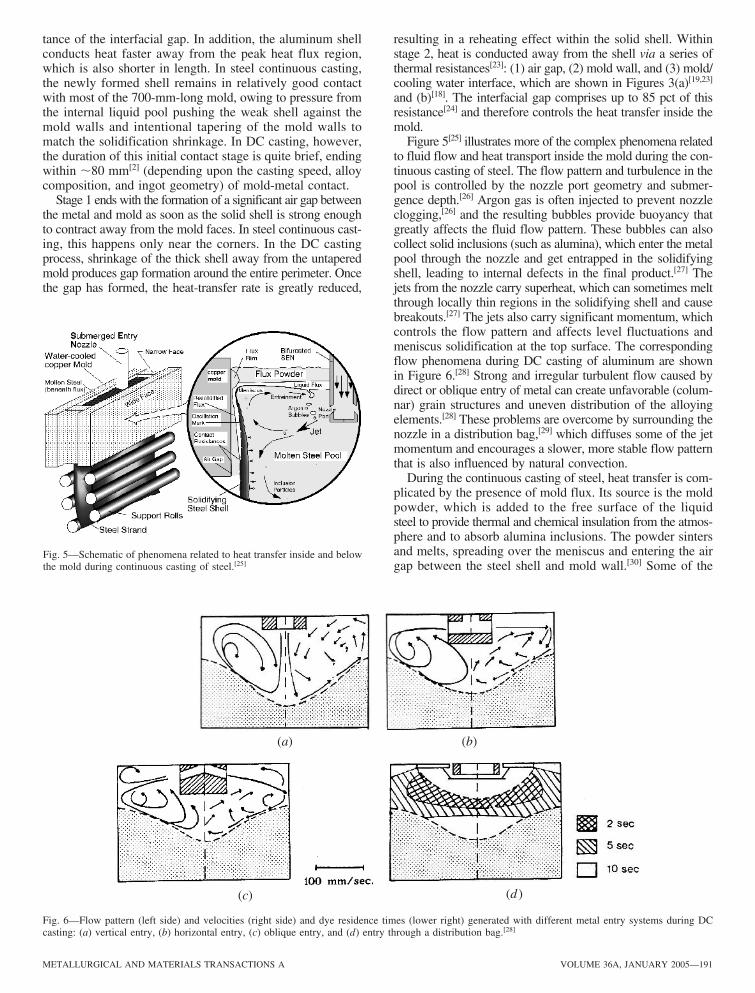