the use of non-contact thin gap sensors in controlling ... · the use of non-contact thin gap...
TRANSCRIPT

Capacitec,Inc. PO Box 819 Ayer, MA 01432 Tel: 978-772-6033 email: [email protected]
The Use of Non-Contact Thin Gap Sensors in Controlling Coater Gap Uniformity
Bryan Manning Capacitec,Inc. PO Box 819 Ayer, MA 01432 Tel: 978-772-6033
email: [email protected]
Presented at the 12th International Coating Science and Technology Symposium September 23-25, 2004 • Rochester, New York
Extended Abstract Comparison of the advantages of technologies to measure thin gaps in coating operations with a
concentration on slot die coaters. Introduction of breakthrough capacitive technology allowing non–
contact measurement of thin gaps from 0.10 mm to 0.76 mm. The use of this technology has
resulted in the possibility of achieving repeatable coater gap uniformity better than 0.25 microns.
Specific examples of thin gap control currently in use by world leaders in adhesive labels, tapes,
films and other converted materials are shown. The full system includes sensor wands, special
wand holders, and signal conditioning electronics and software. The presentation is of interest to
personnel charged with the job of measuring microinch repeatable gaps to control product
uniformity and quality.
1. Introduction Capacitec has been working closely over the past 10 years with the leading global manufacturers of
tapes and films for various commercial and industrial uses. The development was pursued directly
with end users as well as with various coater suppliers.
The common thread between these users is the utilization of slot extruder dies to apply a variety of
very thin chemical, adhesive and photographic coatings to a variety of media.
Specific examples of applications include: • Adhesive coatings onto labels
• Chemical coatings onto films and tapes
• Photographic coatings onto films
• Manufacture of plastic tapes
In a typical applications the coater die slot gap sizes range from 0.006” (150 microns) to 0.024” (600
microns) with a typical set of slots being 0.006”, 0.008”, 0.010”, 0.012”, 0.014” etc. The length of the
slot gap is typically 3 to 6 feet (1 to 2 meters) wide.
Capacitec,Inc. PO Box 819 Ayer, MA 01432 Tel: 978-772-6033 email: [email protected]
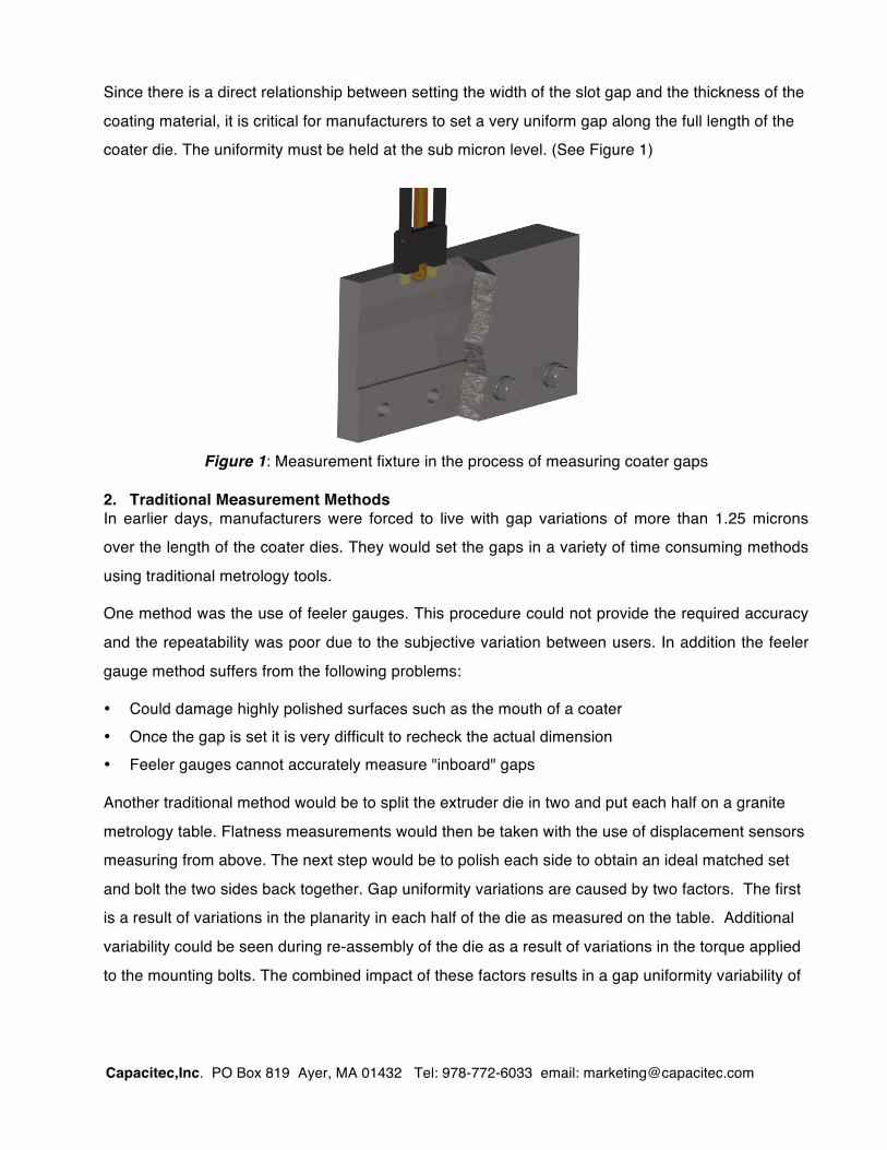
Since there is a direct relationship between setting the width of the slot gap and the thickness of the
coating material, it is critical for manufacturers to set a very uniform gap along the full length of the
coater die. The uniformity must be held at the sub micron level. (See Figure 1)
Figure 1: Measurement fixture in the process of measuring coater gaps
2. Traditional Measurement Methods In earlier days, manufacturers were forced to live with gap variations of more than 1.25 microns
over the length of the coater dies. They would set the gaps in a variety of time consuming methods
using traditional metrology tools.
One method was the use of feeler gauges. This procedure could not provide the required accuracy
and the repeatability was poor due to the subjective variation between users. In addition the feeler
gauge method suffers from the following problems:
• Could damage highly polished surfaces such as the mouth of a coater • Once the gap is set it is very difficult to recheck the actual dimension • Feeler gauges cannot accurately measure "inboard" gaps Another traditional method would be to split the extruder die in two and put each half on a granite
metrology table. Flatness measurements would then be taken with the use of displacement sensors
measuring from above. The next step would be to polish each side to obtain an ideal matched set
and bolt the two sides back together. Gap uniformity variations are caused by two factors. The first
is a result of variations in the planarity in each half of the die as measured on the table. Additional
variability could be seen during re-assembly of the die as a result of variations in the torque applied
to the mounting bolts. The combined impact of these factors results in a gap uniformity variability of

Capacitec,Inc. PO Box 819 Ayer, MA 01432 Tel: 978-772-6033 email: [email protected]
0.25 to 1.0 microns. What manufacturers really needed to control the process was to attain a level
of less that 0.25 microns gap uniformity across the full length and width of the slot.
3. Measurement Solution The benchmark level of less than 0.25 micron gap uniformity of slot die gaps has recently been
accomplished. In fact in some applications it has been exceeded with uniformity being maintained at
levels down to 0.125 microns. The goal was met after several yearsʼ development with close
participation with customers. This section will describe the system components.
3.1 Capacitive Technology The first step in the solution was the selection of capacitive technology as the basis for sensor
design. The choice of capacitive was based on several of its inherent advantages including:
• Non-contact measurement method using ultra thin composite sensors • Linear analog output with excellent repeatability and high temperature capability 3.2 Sensor Wand Selection The capacitive sensors are attached back-to-back on a sensor wand. The configuration, thickness
and material of the sensor wand depend on the application at hand. Sensor wands come in two
groups (Kapton® or Composite) depending on thickness. When very thin gaps are measured (from
0.10 mm to 1.0 mm) the sensor wands are typically made of Kapton® in thickness ranging from
0.10 mm to 1.0 mm. Standard Kapton® wand length 200mm.
3.3 Maximizing Accuracy In the science of capacitive measurement technology there is a relationship between range and
accuracy. The smaller the range, the higher the accuracy and linearity. The selection of the sensor
wand thickness is therefor made in relationship with the gap size. Wand thickness is selected to
create an overall range of 250 microns. This produces an accuracy of ±0.2%FS, or 0.25 microns.
Even higher accuracy can be attained by selecting the wand thickness to be a maximum of 100
microns below the targeted slot gap. These two wand selection criteria combine to give and overall
accuracy of better than ±0.1% FS or 0.1 microns.
3.4 Custom Fixtures An additional discovery uncovered during the design process was the importance of wand
positioning when taking gap measurements. The best measurements were attained when the
sensor wand was held stable in a parallel position relative to the two halves of the coater die. When
Capacitec,Inc. PO Box 819 Ayer, MA 01432 Tel: 978-772-6033 email: [email protected]
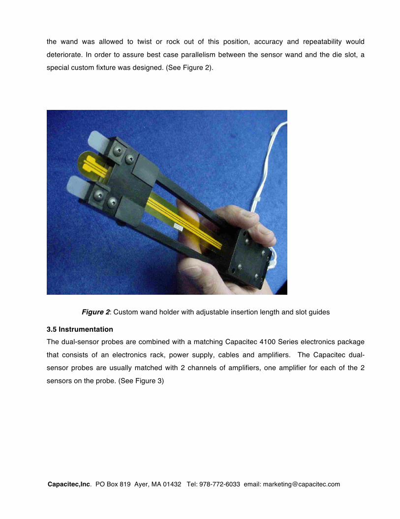
the wand was allowed to twist or rock out of this position, accuracy and repeatability would
deteriorate. In order to assure best case parallelism between the sensor wand and the die slot, a
special custom fixture was designed. (See Figure 2).
Figure 2: Custom wand holder with adjustable insertion length and slot guides
3.5 Instrumentation The dual-sensor probes are combined with a matching Capacitec 4100 Series electronics package
that consists of an electronics rack, power supply, cables and amplifiers. The Capacitec dual-
sensor probes are usually matched with 2 channels of amplifiers, one amplifier for each of the 2
sensors on the probe. (See Figure 3)

Capacitec,Inc. PO Box 819 Ayer, MA 01432 Tel: 978-772-6033 email: [email protected]
Figure 3: Complete 2 channel system including calibration block
3.6 Bargrafx Software The Capacitec BarGrafx™ program was developed under National Instruments' LabView program.
It has a real-time Calibration module which takes analog output voltage and turns it into linear
engineering units using polynomial interpolation (to 4th degree). A general equation editor allows
any linearized channel to be added, subtracted, multiplied or divided from any other linearized
channel. Additional features are an equation editor, a limits module that allows the assigned
bargraph display to reflect upper and lower limits and a data output feature that with standard .txt
store-to data file format. Data can also be directly sent over an RS232 to an external data
acquisition system or computer-based control system.
Figure 4: Calibration system including calibration block and micrometer
Capacitec,Inc. PO Box 819 Ayer, MA 01432 Tel: 978-772-6033 email: [email protected]
4. Maximizing Accuracy
Since most slot die gaps are measured using a hand held tool, the wand positioning can be
inexact, causing greater variation in larger gaps. Compromising to a more limited gap range,
however, yields the desired accuracy and linearity. The selection of the sensor wand thickness
is therefor made in relationship with the gap size. Wand thickness is selected to create an
overall range of 250 microns. This produces an accuracy of ±0.2%FS, or ± 0.5 microns. To
improve accuracy and uniformity beyond this level, a measurement technique utilizing a wand
that measures gaps of no more that 125 microns above the wand thickness is used. This
method results in even higher accuracy of better than ±0.1% FS or ± 0.25 microns. Figure 4
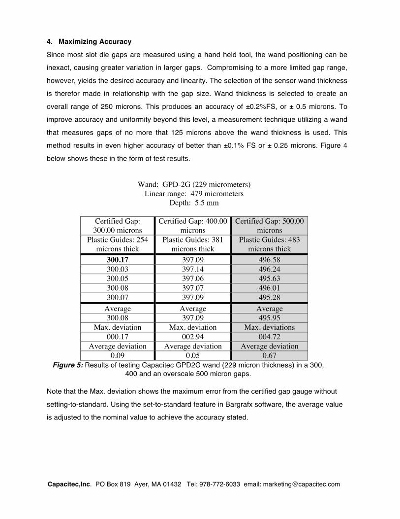
below shows these in the form of test results.
Wand: GPD-2G (229 micrometers)
Linear range: 479 micrometers Depth: 5.5 mm
Certified Gap: 300.00 microns
Certified Gap: 400.00 microns
Certified Gap: 500.00 microns
Plastic Guides: 254 microns thick
Plastic Guides: 381 microns thick
Plastic Guides: 483 microns thick
300.17 397.09 496.58 300.03 397.14 496.24 300.05 397.06 495.63 300.08 397.07 496.01 300.07 397.09 495.28
Average Average Average 300.08 397.09 495.95
Max. deviation Max. deviation Max. deviations 000.17 002.94 004.72
Average deviation Average deviation Average deviation 0.09 0.05 0.67
Figure 5: Results of testing Capacitec GPD2G wand (229 micron thickness) in a 300, 400 and an overscale 500 micron gaps.
Note that the Max. deviation shows the maximum error from the certified gap gauge without
setting-to-standard. Using the set-to-standard feature in Bargrafx software, the average value
is adjusted to the nominal value to achieve the accuracy stated.