the university of asia pacific department of civil · pdf filereferences: water supply and...
TRANSCRIPT

The University of Asia Pacific Department of Civil Engineering
Course No: CE 333 Credit Hours: 3.0 Course Title: Environmental Engineering II (Waste Water Engineering) Course Teacher: Kazi Shamima Akter, Assistant Professor
Lecture Plan (Tentative)
Topics Lec. No
1. Introduction to Environmental Sanitation 8 Sanitation & Health
Definition and Objectives of Sanitation Classification of Wastes and Sanitation Systems
On-site Sanitation Systems for Rural & Low Income Urban Communities Simple Pit Technology, Two Pit Latrine Systems Pour Flash Sanitation Technologies, Septic Tank
2. Waste Water Engineering
10
Conventional Sewerage System Waste Water Collection System Estimation Of Waste Water Flow
Hydraulics Requirements & Design of Sanitary Sewer System Sewer Appurtenances Plumbing System Small Bore Sewerage System Simplified Sewerage System Storm Water and Sullage Drainage System Design
3. Waste Water Treatment & Disposal
10
Waste Water Characteristics Sewage Treatment Methods Preparatory Treatment Primary Treatment Secondary Treatment
Attached growth System Suspended Growth System Effluent Disposal Sludge Treatment and Sludge Disposal

References: Water Supply and Sanitation- Feroz Ahmed and Mujibur
Rahman Wastewater Engineering- Metcalf and Eddy Environmental Engineering-Howard S. Peavy Water Supply and Sewerage- Terence J. McGhee Water Supply and Sanitary Engineering-S. K. Hussain Class Notes
Grading Policy:
Class Assessment and Attendance 10% Class Tests 20% Mid Term Exam 20% Final Exam 50% Note: 3 out of 4 class tests will be considered.

CE 333 Waste Water Engineering
Lecture – 1
Course Teacher: Kazi Shamima Akter, PhD (Assistant Professor)
CE 333 WASTE WATER ENGINEERING
(Credit 3.0, Class Period 3 hours/week)
WHY WASTE WATER ENGINEERING?
OBJECTIVE With increasing population, urbanization and industrialization, production of wastes and waste water have been increasing tremendously. To provide an overview of sanitation and the wastewater systems, treatment methods and processes. Students will be able to acquire knowledge on basic wastewater treatment and process design.
LEARNING OUTCOME Students should be familiar with the design of different sanitation systems and design of unit processes for conventional and advanced wastewater treatment methods.
PROFESSIONAL SCOPE
-- Employment in the water utilities, environmental engineering consultancies, process contractors, equipment manufacturers, suppliers serving local and international water and environment sectors and companies where water and wastewater processing are a major concern.
-- Graduates may also pursue research degrees in water and wastewater treatment.
COURSE OUTLINE
Introduction to Environmental Sanitation
Sanitation & Health
Definition and Objectives of Sanitation
Classification of Wastes and Sanitation Systems
On-site Sanitation Systems for Rural & Low Income Urban Communities
Simple Pit Technology, Two Pit Latrine Systems
Pour Flash Sanitation Technologies
Septic Tank

CE 333 Waste Water Engineering
Lecture – 1
Course Teacher: Kazi Shamima Akter, PhD (Assistant Professor)
Waste Water Engineering
Conventional Sewerage System
Waste Water Collection System
Estimation Of Waste Water Flow
Hydraulics Requirements & Design of Sanitary Sewer System
Sewer Appurtenances
Plumbing System
Small Bore Sewerage System
Simplified Sewerage System
Storm Water and Sullage Drainage System Design
Waste Water Treatment & Disposal
Waste Water Characteristics
Sewage Treatment Methods
Preparatory Treatment
Primary Treatment
Secondary Treatment
Attached growth System
Suspended Growth System
Effluent Disposal
Sludge Treatment and Sludge Disposal
TEXT & REFERENCE
TEXT:
Any standard undergraduate textbook on Wastewater Engineering

CE 333 Waste Water Engineering
Lecture – 1
Course Teacher: Kazi Shamima Akter, PhD (Assistant Professor)
Some Examples:
1. “Water Supply and Sanitation”: Ahmed and Rahman, 2nd ed./reprint, ITN-Bangladesh, 2005
2. “Environmental Engineering” by Peavy, Rowe and Tchobanoglous, Int’l edition, McGraw-Hill, 1991.
3. “Wastewater Engineering” Metcaff and Eddy
REFERENCE: Notes and Handouts provided in Class
INTRODUCTION TO ENVIRONMENTAL SANITATION
Environmental sanitation is a set of actions geared towards improving the quality of the environment and controlling of environmental factors that form links in disease transmission. By doing so, the hope is that living conditions will improve and health problems will decrease. The “solid waste management” (CE 431), “water and wastewater treatment” (CE 333), “industrial waste treatment” and “environmental pollution control” (CE 433), all fall under the umbrella of environmental sanitation.
According to WHO (World Health Organization, 1950), environmental sanitation refers all condition that affect health, including the control of water supply, excreta and wastewater disposal, refuse disposal, housing condition, food protection, atmospheric conditions and the safety of the working environment.
DEFINITIONS OF SANITATION
Sanitation is the hygienic means of promoting health through prevention of human contact with the hazards of wastes.
Sanitation refers to all conditions that affect health, with regard to dirt and infection and especially to the drainage and disposal of sewage and refuse from house.
Sanitation may be defined as the science and practice of effecting healthful and hygienic conditions and involves the study and use of hygienic measures such as:
Safe, reliable water supply;
Proper drainage of wastewater;
Proper disposal of all human wastes;
Prompt refusal of all refuse.

CE 333 Waste Water Engineering
Lecture – 1
Course Teacher: Kazi Shamima Akter, PhD (Assistant Professor)
OBJECTIVES OF SANITATION
The principal objectives of providing sanitary facilities are:
To have improved public health
To minimize environmental pollution
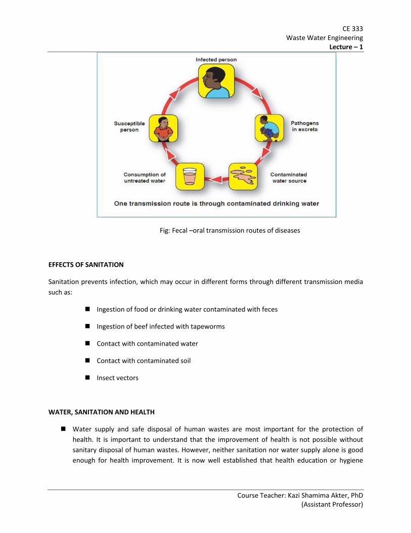
TRANSMISSION OF DISEASES
Excreta from infected persons can cause infection in other persons can cause infection in other persons in two different ways:
Pathogens in the excreta of an infected person reach another person and initiate infection. These are the excreted infections.
Infections in other persons are caused by transmission of excreted pathogens via insects such as flies and mosquitoes and rodents such as rats, which act as vectors.
The number of pathogens excreted is termed the excreted load, which is governed by:
Latency (time to become infective)
Persistence (time of survival)
Multiplication (time to multiply)
Infected Excreta
Infected Excreta Vector Breeding
New Infections
CE 333 Waste Water Engineering
Lecture – 1
Course Teacher: Kazi Shamima Akter, PhD (Assistant Professor)
Fig: Fecal –oral transmission routes of diseases
EFFECTS OF SANITATION
Sanitation prevents infection, which may occur in different forms through different transmission media such as:
Ingestion of food or drinking water contaminated with feces
Ingestion of beef infected with tapeworms
Contact with contaminated water
Contact with contaminated soil
Insect vectors
WATER, SANITATION AND HEALTH
Water supply and safe disposal of human wastes are most important for the protection of health. It is important to understand that the improvement of health is not possible without sanitary disposal of human wastes. However, neither sanitation nor water supply alone is good enough for health improvement. It is now well established that health education or hygiene

CE 333 Waste Water Engineering
Lecture – 1
Course Teacher: Kazi Shamima Akter, PhD (Assistant Professor)
promotion must accompany sufficient quantities of safe water and sanitary disposal of excreta to ensure the control of water and sanitary related diseases.
Figure: Interrelationship between water, sanitation and health education
CLASSIFICATION OF WASTES
Human Wastes or Human Excreta:
Refers to only human faeces and urine.
Usually not combined with other liquid or solid wastes.
Also known as night soil, when collected without dilution in large volumes of water.
Municipal Sewage/ Wastewater:
Liquid waste conveyed by a sewer.
May include domestic and industrial discharges as well as storm water, groundwater, infiltration and inflow.
Domestic Sewage:
Liquid Wastes, which originate in the sanitary conveniences, e.g., water closets, urinals, bath, sinks etc. of the dwellings, commercial facilities and institutions in a community.
CE 333 Waste Water Engineering
Lecture – 1
Course Teacher: Kazi Shamima Akter, PhD (Assistant Professor)
Sullage:
Liquid discharges from kitchens, wash basins etc. and excludes human excreta.
Less foul than domestic sewage.
Can be discharged through open surface drains in unsewered areas.
Industrial Wastes:
Include the liquid discharges from spent water in different industrial processes such as manufacturing and food processing.
Storm Water:
It is the surface runoff during and immediately after rainfall, which enters sewer through inlets.
It is not as foul as sanitary or industrial sewages.
It can be carried through open drains or channels and disposed of in natural rivers or streams without any treatment.
Solid Wastes:
It includes all materials which are normally solid and are discarded as useless or unwanted during human activities.
Domestic solid waste is a composition of organic food wastes, paper and paper products, wood, plastics, leather and rubber materials, rags and textile products, glass, metals, inert stone and other bulky wastes.
Solid wastes from factories and industries often consist of packaging, spoiled material and unwanted by-products.

CE 333 Waste Water Engineering
Lecture – 1
Course Teacher: Kazi Shamima Akter, PhD (Assistant Professor)
FUNCTIONS OF SANITATION SYSTEM
A sanitation system involves all arrangements necessary to store, collect, process and delivers human wastes or other forms of wastes back to nature in a safe manner.
With respect to human waste management, sanitation systems may be considered to have the following functions -
Excretion and storage
Collection and transportation
Process / Treatment
Disposal / Recycle
TYPES OF SANITATION SYSTEM
Based on the fact, whether the waste is stored, treated and disposed of at the point of generation or transported to somewhere else for treatment and / or disposal, sanitation systems may be divided into the following two categories –
On-site systems Off-site systems
Based on the methods of collection and conveyance, sanitation systems are of the following types –
Dry systems Wet systems
Based on the fact, whether the systems allows infiltration, sanitation systems are of two types as follows –
Permeable / Unconfined systems Confined systems
ON-SITE SANITATION SYSTEMS (FOR RURAL & LOW INCOME URBAN COMMUNITIES)
Wastes are collected, treated and disposed of at the point of generation.
Examples are – pit latrines and septic tank systems.
Widely used in rural areas of both developed and developing countries, even in urban areas in absence of costly sewerage systems.
Modification of this system includes ventilated pit latrine, pour-flush single and double-pit latrines, aqua privies, septic tanks and so on.

CE 333 Waste Water Engineering
Lecture – 1
Course Teacher: Kazi Shamima Akter, PhD (Assistant Professor)
The principles of on-site system are-
Infiltration of liquids into the soil.
Solids are retained, digested aerobically and have to be removed or a new pit has to be dug at regular intervals.
It is primarily designed to dispose of human excreta.
Wastewaters from cooking, clothes washing and bathing are collected in small drains &disposed of in soakaways for infiltration.
This system is most suitable for sparsely settled rural areas with low population density and low water consumption because of the system’s dependence on the infiltration capacity of the soil for the disposal of the liquid portion of excreta.
This system is not feasible for areas with high population density, high water consumption, and low infiltration rate of soil or high groundwater table.
OFF-SITE SANITATION SYSTEMS
Waste is collected and transported to somewhere else for treatment and disposal
E.g. bucket latrine systems and conventional sewerage systems.
The basic elements of this system are collection, transportation, treatment and disposal and/or reuse.
The waste is collected either through house sewers or manually using buckets or vaults; transported either by cart, truck or sewer system to a suitable distant place where it is treated prior to disposal or reuse.
Collection and transportation of the wastes through a sewer reticulation system requires that the waste be diluted by water. It is essential, piped water supply be available in areas where this system is to be applied.
This waterborne system is by far the most satisfactory system of waste disposal provided sufficient funds are available for its construction and maintenance.
DRY SANITATION SYSTEMS
In dry systems no water is used for dilution of the wastes.
They are usually applied in unsewered areas with no piped water supply, e.g., pit latrine systems (on-site) and bucket latrine systems (off-site).
CE 333 Waste Water Engineering
Lecture – 1
Course Teacher: Kazi Shamima Akter, PhD (Assistant Professor)
WET SANITATION SYSTEMS
In the wet system, the waste is diluted with flushes of water
Suitable where piped water supply systems are available, e.g., septic tank systems (on-site) and conventional sewerage systems (off-site)
PERMEABLE/UNCONFINED SYSTEMS
The liquid part of the wastes is allowed to infiltrate.
Cause potential pollution of the groundwater.
Example - pit latrines.
CONFINED SYSTEMS
The liquid portion of the wastes is not allowed to infiltrate into the ground.
No potential for groundwater pollution.
Example – aqua privies, septic tanks etc.
CRITERIA FOR GOOD SANITATION SYSTEM
Simple and inexpensive in construction and operation
Should not contaminate surface soil, surface wateror groundwater
Minimum handling of excreta and free from odour and unsightly conditions
No access to flies, insects and animals
Should use little or no water
Should require little supervision and maintenance
Should handle all waste and wastewater
Should use little or no mechanical equipment
APPROPRIATENESS OF SANITATION SYSTEMS
Purpose of sanitation:
Health
Privacy
Convenience
CE 333 Waste Water Engineering
Lecture – 1
Course Teacher: Kazi Shamima Akter, PhD (Assistant Professor)
Cleaner Environment
Prestige/Status
A good sanitation system should, therefore, be able to meet all the different requirements of the people.
Suitability of Sanitation System:
Level of Water supply
Population Density
Level of Water supply:
---- On site pit latrine system would not be appropriate with piped water supply.
---- Water borne sewerage system (e.g., conventional sewerage system) is not a feasible option with bucket carried or hand-pump water supply.
Population Density:
----- On site system is more appropriate for low-density rural setting.
----- Off-site systems more suitable for high density urban centers.
PERSPECTIVE: BANGLADESH
Important factors for sanitation in Bangladesh
Housing density
Water supply service level
Difficulties associated with pit latrines
Operation and maintenance
Soil permeability
Groundwater pollution

CE 333 Waste Water Engineering
Lecture – 1
Course Teacher: Kazi Shamima Akter, PhD (Assistant Professor)
FIGURE: APPROPRIATENESS OF SANITATION SYSTEMS
URBAN
RURAL
Population Density
Level of
Water
Supply Dug well
Hand Pump
Stand-post House Connection
Dry Off-site Sanitation Wet Off-site Sanitation
Dry On-site Sanitation
Wet On-site Sanitation
CE 333 Waste Water Engineering
Lecture – 2
Course Teacher: Kazi Shamima Akter, PhD (Assistant Professor)
CE 333 WASTE WATER ENGINEERING
(Credit 3.0, Class Period 3 hours/week)
LOW-COST SANITATION TECHNOLOGIES
A) Pit Latrine
B) Pour-flush Latrines (where a water seal is maintained with low-volume of flushing)
All forms of pit latrines are not fully sanitary. With slight modifications in design and with some interventions conventional pit latrines could be improved to be hygienic.
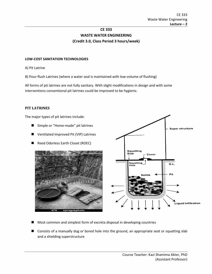
PIT LATRINES
The major types of pit latrines include:
Simple or “Home-made” pit latrines
Ventilated Improved Pit (VIP) Latrines
Reed Odorless Earth Closet (ROEC)
Most common and simplest form of excreta disposal in developing countries
Consists of a manually dug or bored hole into the ground, an appropriate seat or squatting slab and a shielding superstructure

CE 333 Waste Water Engineering
Lecture – 2
Course Teacher: Kazi Shamima Akter, PhD (Assistant Professor)
Urine and other liquids soak into the ground and solid materials are retained and decomposed in the pit
Forms:
Direct pit latrine-Excreta falls directly into a pit underneath the user
Off-set pit latrine-Excreta pass through a short pipe or a channel to a pit a few meters away
Partly off-set pit latrine-When part of the pit is under the shelter and part is outside
The pit should be as large as possible, however, it should not be more than 1.5 m (commonly 1.0-1.5 m) wide, and otherwise construction of cover slab will be more expensive.
Soils with permeability below 2.5 mm/hour are unsuitable for pit latrines, as liquid fraction of excreta is unable to infiltrate into soil.
Pits in unstable soils must be fully lined (otherwise, collapse of superstructure). Materials used: concrete blocks, bricks, cement-stabilised soil blocks, masonry, perforated oil drums etc.
A distance of at least 10.0m should be provided between pit and a source of drinking water (to avoid possible contamination).
At least 2m distance between pit bottom and water table.
Adequate ventilation by leaving openings above and below door or by constructing a spiral wall without door.
Depth of pit: depends on ground water table, soil condition. 5-ring pits (@ 1 ft. per ring) are common.
Effective Pit Volume: V = C × P × N
where, V = Effective volume of the pit, m3
C = Solids accumulation rate, m3/person/year
P = Number of persons, expected to use the latrine
N = Design life in years
Total size of pit latrine can be determined from:
V = 1.33 × C × P × N (for latrines ≤4.0m in depth)

CE 333 Waste Water Engineering
Lecture – 2
Course Teacher: Kazi Shamima Akter, PhD (Assistant Professor)
The factor 1.33 is incorporated to ensure a clear space above the remains of the excreta at the end of design period, allows 75% of the pit to be filled at the end of design period.
Wet pit: 0.04 m3/person/year (0.02 - 0.04)
Typical values of C:
Dry pit: 0.06 m3/person/year (0.03 - 0.06)
(Note: Accumulation rate is lower for wet pit (i.e., pit below GWT) because biodegradation is faster under wet condition)
Effective Pit Volume
where, d = diameter of pit
V = (πd2/4) h ..... (2)
h = effective depth of pit
Assuming a suitable diameter (maximum permissible diameter is 1.5 m) of pit, the effective pit depth, h can be obtained. Then the total depth will be effective depth plus the desired free space above inlet of the pit. Usually a free space of 0.5 m is kept at top of the pit. Therefore,
Total Depth of pit, H = Effective Depth of Pit, h + 0.5 m
Excreta deposited into the pit have two essential components-
Liquid fraction of excreta (mainly urine, small amount of water due to anal cleansing, slab )
Fecal solids in excreta that are digested anaerobically to produce (i) gases such as methane, carbon dioxide and hydrogen sulphide, which are exhausted from the pit via the vent pipe, and (ii) soluble compounds which are either further oxidised in the pit or are carried into the surrounding soil by infiltrating liquid fraction.
In dry pits (not extend below groundwater table), solids accumulation rate varies between 0.03 and 0.06 m3/person/year and in wet pits between 0.02 and 0.04 m3/person/year (for design, 0.06 and 0.04).
Accumulation rates are lower in wet pits because biodegradation is faster under wet conditions than under just conditions in dry pits.
Advantages
Low investment for construction. Enables construction without depending on expert inputs.
Design is readily available; local materials can be used
Free from the risk of falling a child into it and hence suitable for children.

CE 333 Waste Water Engineering
Lecture – 2
Course Teacher: Kazi Shamima Akter, PhD (Assistant Professor)
Excrements are better contained than in open defecation.
Unit can serve one or several households.
Easy operation and maintenance.
Pit latrines use no water for flushing.
Disadvantages
Potential odour and flies problem in simple pit latrine.
Require access to open ground and digging of new pits or emptying of existing ones every few years.
Emptying of pits can be very difficult (may require manual labour, pits may collapse). Also manual desludging poses health hazard
Toilets cannot be situated in houses, hence lack of privacy and safety concerns especially during night time.
Re-location of individual leach-pits difficult in densely populated areas
They cannot be used at all in crowded areas, on rocky ground, where the groundwater level is high or in areas periodically flooded
Operation and maintenance
Regular cleaning of squatting slab
A tight fitting lid should be placed on squatting hole
Water should be available for anal cleansing
Sprinkling of ash or sawdust to reduce smell and insect breeding
Non-biodegradable materials like stone, glass, plastics etc. shouldn’t be thrown into pit, since reducing effective pit volume.
Emptying of pit (manually or mechanically)
Constructing a new pit & emptying existing one.
CE 333 Waste Water Engineering
Lecture – 2
Course Teacher: Kazi Shamima Akter, PhD (Assistant Professor)
VENTILATED IMPROVED PIT (VIP) LATRINE Scope of use Families that use solid materials like news paper, stone, etc. for anal cleansing are not recommended to use poor-flush latrines as water seal is likely to become blocked or broken. In such cases a latrine direct access to the pit is more appropriate and therefore, ventilated improved pit (VIP) may be a good solution. Basic difference from other pit latrines The basic difference of VIP Latrine from pit latrine is, it requires a vent pipe and design should be such that it maintains continuous airflow. This also increases the cost of super structure. Elements of ventilated pit Latrines: • Pit; • Cover slab; • Vent pipe - large enough ≥ 150mm dia. to allow free passage of air with fly screen • Super structure. Types of ventilated pit Latrines: (1) Single Pit VIP Latrine -Suitable where mechanical emptying is possible when the pit is full -Manual emptying is not recommended as the excreta at the top are fresh and potentially dangerous for the emptier -Usually designed for longer life (e.g., 10 years) where feasible and act as permanent structure. -When a single pit VIP latrine becomes full, there are two options- Construction of a new latrine Emptying the existing pit (2) Twin Pit VIP Latrine -Two separate pits, with the superstructure located centrally over the off-set pits. -The slab coverin gthe pit has two squat holes, one over each pit. -Only one hole and pit are used at a time. The hole over the other piut is covered by a concrete plug. -When the pit is full (e.g., in 1-3 years), its squat hole is covered up and the second pit is put into service. -When the second pit is full, the contents of the first pit are removed and it is put back into service. This cycle continues. Main advantages of VIP Latrine: • Minimum water requirement; • Control odour and insects; • Low-cost; • Easy to construct and maintain. Major problems with VIP Latrine: • Requirement of unobstructed ventilated pipe (even 0.5m higher than surrounding building) makes the latrine more suitable for low-density area than high-density urban area; • Improper design / climatic condition (may not be suitable to maintain air flow);

CE 333 Waste Water Engineering
Lecture – 2
Course Teacher: Kazi Shamima Akter, PhD (Assistant Professor)
• Potential for groundwater pollution.
DESIGN CONSIDERATION OF VIP LATRINES:
Design life- -Single pit VIP : at least 10 years -Twin pit VIP :1-3 years Pit Dimension- -Cross section ≤ 2 m2, to avoid cover slab with larger spans. Example: VIP latrines serving single household: Pit dimension: 1-1.5 m diameter 1-1.5 meter width (square) Vent Pipe: Material: PVC, micro PVC, brick etc. Height: 500mm higher than roof (flat roof) 500 mm above the highest point of roof (sloping roof) Internal diameter: enough to achieve a ventilation rate of 20m3/hr Current Recommendation: minimum internal size of vent pipe- PVC: 150 mm dia Brick: 230 mm square

CE 333 Waste Water Engineering
Lecture – 2
Course Teacher: Kazi Shamima Akter, PhD (Assistant Professor)
Others: 230 mm dia Fly screen specification- Purpose: to prevent passage of mosquito, flies Size: aperture≤1.2mmX1.5mm Material: corrosion resistant, able to withstand - intense rainfall, high temperature, sunlight preferably stainless steel. Relocation & emptying of pits: There are options. Constriction of new latrines on an adjacent site or emptying the existing pit. It depends on several factors. REED ODOURLESS EARTH CLOSET (ROEC) The Reed odourless earth closet (ROEC) is a variation on the ventilated improved pit latrine. With ROEC, the pit is fully off-set from the superstructure and is connected to the squatting plate
by a curved chute as shown in the following figure.
Figure: The Reed Odourless earth Closet (ROEC)
The ROEC is fitted with a vent pipe to control odour and insect nuisance. It is claimed that the
chute, in conjunction with the ventilation stack, encourages vigorous air circulation down the latrine, thereby removing odours and discouraging flies.
This latrine is common in southern Africa. The design considerations and design principles of ROEC are similar to those of a single pit VIP latrine.

CE 333 Waste Water Engineering
Lecture – 2
Course Teacher: Kazi Shamima Akter, PhD (Assistant Professor)
Advantages of ROEC: Larger pit can be used Pit can be easily emptied people feel more secure when using the latrines Aesthetically more acceptable
Disadvantages of ROEC: The ROEC chute easily become with excreta, thereby providing a possible site for fly breeding and
odour nuisance Regular cleaning of the chute either by a long-handled brush or by small amount of water Potential for groundwater pollution
1. Local authority in a village is offering pre-cast concrete rings of 1.0 m diameter and 0.3 m depth of concrete slab to cover it at a subsidized rate. Design a simple pit latrine for a family of 7. The soil is unconsolidated/loose and the GWT is 5.0 m below the ground surface. The family wants the latrine to serve for 4 years. (Note: Change design parameter as you find appropriate.)
Problems to solve:
2. Repeat the problem 1, if the latrine has to serve 2 families, each with 7 members. GWT is high,
located 4.0 m below the ground surface. Design life cannot be less than 2 years and a 2.0 m gap must be provided between the pit bottom and GWT.
3. A farmer excavated 1.5 m x 2.0 m x 2.5 m (depth) pit for construction of a room which he now wants to convert into a pit latrine. Requirements/ constraints are: Water availability is limited Excreta cannot be seen through squatting hole.
Design a suitable latrine and find design life for 6 persons. Consider low GWT. The pit is to be constructed as a permanent one with brick lining.
Remember: a) Design up to the number of rings.
b) Check for GWT provision.
c) Show the detailing.

CE 333 Waste Water Engineering
Lecture – 2
Course Teacher: Kazi Shamima Akter, PhD (Assistant Professor)
Solutions of Problems
1) A vent pipe for the pit
: Problem 1: Effective Pit Volume V = C × P × N Where, P = 7 = 0.06 × 7 × 4 N = 4 yrs = 1.68 m3 C = 0.06 m3/person/year (Considering dry pit) Cross sectional area of pit = (πd2/4) = 0.785 m2
Effective Pit depth = 1.68/0.785 = 2.14 m Design Pit depth = 2.14 + 0.5 = 2.64 m (free board/space =0.5m) No. of rings required = 2.64/ 0.3 = 8.8 ≈ 9 rings (Height of ring = 0.3m) But to use more than 5-6 rings is not realistic. Considering N = 3 yrs V = 0.06 × 7 × 3 = 1.26 m3
Effective Pit depth = 1.26/0.785 = 1.61 m Design depth = 2.11 m Rings required = 2.11/ 0.3 = 7 rings Possible but construction could be difficult. Actual depth of pit = 7 × 0.3 = 2.1 + 2 = 4.1m Consider N = 2 yrs V = 0.84 m3
Effective Pit depth = 1.07 m Design depth = 1.57 m Rings required = 1.57/ 0.3 = 5.23 ≈ 6 rings Actual depth of pit = 6 × 0.3 = 1.8 m 1.8 + 2 = 3.8 < 5m (ok) Also recommended:
(150 mm dia. PVC pipe, top of the vent pipe is 500mm higher than highest point of roof) 2) Use of suitable cover for the squatting hole, when latrine not in use
Problem 2: Depth of GWT = 4m 4-2 = 2m; Pit bottom can not be more than 2m below ground surface. Now, V = C × P × N = 0.06 × 7 × 2 × 3 = 1.68 m3
Effective Pit depth = 1.68/0.785 = 2.14 m Design depth = 2.14 + 0.5 = 2.64m > 2m; Can not be recommended. Consider twin pit (or single pit with regular desludging)
CE 333 Waste Water Engineering
Lecture – 2
Course Teacher: Kazi Shamima Akter, PhD (Assistant Professor)
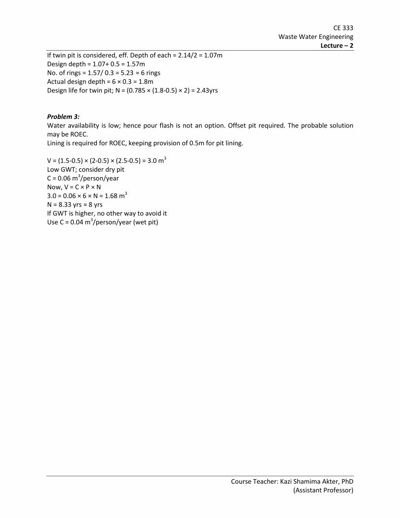
If twin pit is considered, eff. Depth of each = 2.14/2 = 1.07m Design depth = 1.07+ 0.5 = 1.57m No. of rings = 1.57/ 0.3 = 5.23 ≈ 6 rings Actual design depth = 6 × 0.3 = 1.8m Design life for twin pit; N = (0.785 × (1.8-0.5) × 2) = 2.43yrs Problem 3: Water availability is low; hence pour flash is not an option. Offset pit required. The probable solution may be ROEC. Lining is required for ROEC, keeping provision of 0.5m for pit lining. V = (1.5-0.5) × (2-0.5) × (2.5-0.5) = 3.0 m3
Low GWT; consider dry pit C = 0.06 m3/person/year Now, V = C × P × N 3.0 = 0.06 × 6 × N = 1.68 m3
N = 8.33 yrs ≈ 8 yrs If GWT is higher, no other way to avoid it Use C = 0.04 m3/person/year (wet pit)

CE 333 Waste Water Engineering
Lecture – 3
Course Teacher: Kazi Shamima Akter, PhD (Assistant Professor)
CE 333 WASTE WATER ENGINEERING
(Credit 3.0, Class Period 3 hours/week)
WATER SEAL (POUR-FLUSH) TECHNOLOGIES:
A further improvement to the pit latrine can be obtained with a water-seal. The pour-flush latrine has three major components parts: (a) the superstructure, (b) The latrine
pan with its integral water seal and (c) a single or altering twin leach pits. Water-seal is a U-pipe filled with water, attached below the squatting pan that completely
prevents passage of flies and odours. The water-seal is only 15-25 mm deep and the latrine can be flushed by hand using 1.5 to 2.0
litres of water. The latrine can also be located, if desired inside the house with off-set pit. Small quantity of water used in a pour flush toilet is sufficient to carry the excreta to a soakage
pit up to 80m away.
Types of Pour-flush Pit Latrine:
(1) This is the modification of the simple pit latrine in which the squatting plate is provided with a 25 mm water seal and is placed directly over the pit.
Direct Pit Pour-flush Latrine
Figure: The Direct Pit Pour-flush Latrine

CE 333 Waste Water Engineering
Lecture – 3
Course Teacher: Kazi Shamima Akter, PhD (Assistant Professor)
(2) In this system, a completely off-set pit is connected to the pour-flush pan by a short length of 100 mm diameter pipe. This type of latrine can be installed inside the house, as it is free from faecal odour and insect problems, thus avoiding the need for a separate superstructure.
These latrines can be of two types – (a) single off-set pit pour-flush latrine and (b) alternating twin off-set pit pour-flush latrine.
Off-set Pit Pour-flush Latrine
Figure: Single Off-set Pit pour-flush Sanitary Latrine
Alternating twin off-set pit pour-flush latrine
The alternating twin-pit system comprises (a) a squatting pan and (b) a Y-junction for directing excreta from squatting pan to either of the two leach pits.
The pits are used alternately and at a given time only one pit is in use. When the first pit is full, the flow of excreta is directed to the second pit through a Y-junction and contents of the first pit are left to decompose.
The contents of the first pit decompose to safe, pathogen-free humus within 18 to 24 months. The contents of the first pit may then be dug out and the pit is kept ready for reuse.

CE 333 Waste Water Engineering
Lecture – 3
Course Teacher: Kazi Shamima Akter, PhD (Assistant Professor)
Figure: Alternating twin off-set pit pour-flush latrine
Functions of pour-flush latrines:
After each use, the latrine is manually pour-flushed with about 2-3 liters of water (compared to 10-20 liters used in conventional toilets)
The water seal provides a barrier against odour and insect.
From excreta, flush water and wash water around 10-20 liters/capita/day (lpcd) of wastewater enter into the pit.
The pit has to provide sufficient volume for solids storage, as well as sufficient area for the wastewater to infiltrate into the soil.
It requires that the soil has sufficient long term infiltrative capacity. If the soil is unsuitable for infiltration, the liquid effluent can be removed by other means e.g., by connection to the sewerage system if available.
CE 333 Waste Water Engineering
Lecture – 3
Course Teacher: Kazi Shamima Akter, PhD (Assistant Professor)
Suitability of pour-flush latrine types:
Pour-flush latrines may be used in both rural and urban areas provided they are appropriately designed and that they can rely on water availability for flushing, and for maintaining the water seal.
Single pits may be appropriate in urban areas only if they can be desludged mechanically by a vacuum tanker, since their contents are nor pathogen free.
Twin-pits are recommended if the pits are to be desludged manually, as the resting period ensures that the contents to be removed are substantially free of pathogens.
Design Considerations for Pour-flush Latrines
The shape of pits can be circular, square, rectangular or even triangular depending on the shape and size of the site.
Minimum water requirement is 1.5 to 2.0 liters for flushing the toilet. For ease in emptying and avoiding the possibility of groundwater pollution pits will be shallow in
depth. In most areas in Bangladesh pits should not exceed 1.8 m. Pits may be lined with burnt clay, concrete, brick masonry, or even bamboo. A free space should be kept over inlet of the pit. In practice, 0.5 m of free space at top of the pit is
usually kept above the inlet. Bottom of pit should remain undisturbed and unsealed. Safe distance between pits and tubewells or any other water body should be at least 10 m. Permeability of surrounding soil is important for function of the pit latrines. Sandy or silty soil
with/without clay is considered ideal. For pits in compacted clayey soil of low permeability, such as in the Barind Tract, a sand envelope of at east 0.3 meter should be provided around the pits.
Distance between two pits for twin pit latrines should be, at least, equal to the effective depth of pits, which is measured from the inlet pipe to bottom of the pit.
Design for pits of Pour-flush Latrines
Leach pits for pour-flush Latrines have to be designed for storage and digestion of excreted solids as well as infiltration of the liquid waste into the surrounding soil. Designing for storage and digestion of solids is exactly the same as for other pit latrines. Infiltration of the liquid effluent requires sufficient pit-soil interface area depending on the long-term infiltration capacity of the soil.
Pit effluent enters the soil first by infiltrating the pit-soil interface, which is partially covered in a bacterial slime layer, and then by percolating away through the surrounding soil. It is suggested that simple percolation tests, which measure how quickly clean water passes thorough undisturbed soil, should not be used to measure infiltration of pit effluent. The long-term infiltration rate depends on the type of soil and suitable design values are given in Table 1.

CE 333 Waste Water Engineering
Lecture – 3
Course Teacher: Kazi Shamima Akter, PhD (Assistant Professor)
Table 1: Design Values for Long-term Infiltration Rates for Wastewater into Various Soils
Soil Type Long term infiltration rate, I (l/m2-day)
Sand 50 Sandy loam 30 Porous loam, porous silty clay loam 20 Compact silty loam, clay 10
The side wall area required for infiltration, (Ai, m2) depends on the wastewater flow (Q, l/day) and the
long-term infiltration rate according to the following relationship:
Ai = Q / I
The wastewater flow depends on the number of users, frequency of flushing, flush volume, urine volumes and amount of water used for anal cleansing. Generally the flow varies between 5-20 lcd.
The pit volume, Vi (m3) corresponding to the sidewall area can now be calculated. For a circular pit of
diameter, D,
Vi = πD2 h/4 ........... (1)
Where h, the height of the sidewall area = Ai / πD
Vi = Ai D/4
i.e., Vi = QD / 4I ............ (2)
For alternating twin-pits, the effective volume of each pit is calculated either using this equation or Vs = C x P x N, whichever is greater.
For single pit pour-flush latrines, the effective volume is given by:
V = Vs + Vi ........... (3)
This estimate however, is slightly conservative as some infiltration would also occur through the side wall area corresponding to Vs. But this better allows restoration of the infiltrative capacity after emptying; In case of alternative twin-pits this restoration occurs during the rest period.
Advantages of Pour-flush Pit Latrine:
Less expensive compared to conventional latrines. Offers appropriate and hygienic solution for excreta disposal. Requires less volume of water for flushing (1-3 lit/flush only). Can be upgraded to connect to a sewerage system or septic tank system.

CE 333 Waste Water Engineering
Lecture – 3
Course Teacher: Kazi Shamima Akter, PhD (Assistant Professor)
Eliminates odour release, insect and fly breeding. Safe for children. Can be located inside the house. Potential for resource recovery using the sludge as soil conditioner. Easy construction and maintenance. Twin pit latrine can serve as a permanent structure because of its pits is used alternatively.
Disadvantages of Pour-flush Pit Latrine:
Requires separate sullage disposal facilities. Water (at least 4 litres / person / day) must be available throughout the year. Water seal may be clogged easily if garbage is thrown into it. Construction is difficult and expensive in areas with high ground water and shallow soil overlying
hard rock. Risk of polluting ground water and/or nearly water sources. Construction and maintenance of twin pit pour-flush latrine is difficult.
SEPTIC TANK:
A septic tank is a key component of the septic system, a small-scale sewage treatment system common in areas with no connection to main sewage pipes provided by local governments or private corporations.
The term "septic" refers to the anaerobic bacterial environment that develops in the tank and that decomposes or mineralizes the waste discharged into the tank.
Scope: Wherever the conventional sewerage system has not been feasible due to technical or economic reasons.
A septic tank is a buried watertight receptacle.
It is designed and constructed to -
receive wastewater from a home
separate the solids from the liquid
provide limited digestion of organic matter
store solids
allow the clarified liquid to discharge for further treatment and disposal

CE 333 Waste Water Engineering
Lecture – 3
Course Teacher: Kazi Shamima Akter, PhD (Assistant Professor)
Settleable solids and partially decomposed sludge settle to the bottom of the tank and gradually build up.
A scum of light-weight material including fats and greases rises to the top.
The partially treated effluent is allowed to flow through an outlet structure just below the floating scum layer.
Partially decomposed liquid can be disposed of through soil absorption systems, soil mounds, evaporation beds or anaerobic filters depending upon the site conditions.
Processes in the Septic Tank:
No external or internal moving parts or added chemicals are used
The natural processes that take place within the tank are complex and interact with each other.
The most important processes that take place within the tank include -
separation of suspended solids,
digestion of sludge and scum,
stabilization of the liquid and
growth of microorganisms.
Figure: Components of a Septic Tank

CE 333 Waste Water Engineering
Lecture – 3
Course Teacher: Kazi Shamima Akter, PhD (Assistant Professor)
(a) Separation of suspended solids
It is a mechanical process which results in the formation of three distinct layers in the septic tank - a layer of sludge at the bottom, a floating layer of scum on the top and a relatively clear layer of liquid in the middle.
(b) Digestion of sludge and scum
Anaerobic bacteria degrade the organic matter in the sludge as well as in the scum and as a result of this bacterial action, volatile acids are formed at the first instance and eventually are converted mostly to water, carbon dioxide and methane.
(c) Stabilization of the liquid
Organic materials in the liquid are stabilized by anaerobic bacteria, which break down complex substances into simpler ones in a process similar to the one that take place in the sludge layer.
(d)
• the sludge layer at the bottom
Growth of microorganisms
A large variety of microorganisms grows, reproduce and die during the biodegradation processes that take place in the tank. Most of them are attached to organic matter and are separated out with the solids. Although there is an overall reduction in the number of microorganism, a large number of bacteria, viruses, protozoa and helminths survive through the processes in the tank and remains active in the effluent, the sludge and the scum.
As the influent enters into an anaerobic Septic Tank, it separates into 3 distinct layers:
• the floating layer of scum on the top
• a relatively clear zone of liquid in the middle.
Performance of a Septic Tank:
Under normal design conditions-
reduction in BOD is 25-50%
reduction in suspended solids is up to 70%
The factors affecting the performance of a septic tank are –
Retention time
Ambient temperature
Nature of the influent wastewater e.g., organic content of the wastewater
CE 333 Waste Water Engineering
Lecture – 3
Course Teacher: Kazi Shamima Akter, PhD (Assistant Professor)
Positions of the inlet and outlet devices in the tank
Design of a Septic Tank:
-Based on Brazilian septic tank code.
-The tank is considered to be made up of four zones, each of which serves a different function:
• Scum storage zone
• Sedimentation zone
• Sludge digestion zone
• Digested sludge storage zone
(a)
Scum accumulates at approximately 30-40 % of the rate at which sludge accumulates, so the tank volume for scum storage (Vsc) can be taken as 0.4 times the volume for sludge storage (Vsl).
i.e.. Vsc = 0.4 Vsl .......... (1)
Scum storage
(b)
The time required to allow sedimentation of settleable solids decreases with the number of people served according to the following equation:
th = 1.5 – 0.3 log (Pq) .......(2)
where, th = minimum mean hydraulic retention time
for sedimentation. days
P = contributing population
q = wastewater flow per person, l/day
Sedimentation
Retention times in septic tanks are longer than those normally employed in raw sewage sedimentation tanks. This is because of the fact that septic tanks are required to intercept solid that enter the tanks with waste inflow as well as solids, which rise up from the sludge layers through flotation by the gases

CE 333 Waste Water Engineering
Lecture – 3
Course Teacher: Kazi Shamima Akter, PhD (Assistant Professor)
produced due to anaerobic digestion. Often a minimum mean hydraulic retention time of one day is used. The value of th used should not be less than 0.2 days.
The tank volume for sedimentation, Vh (m3) is given by:
Vh = 10-3 P q th ................. (3)
Figure: Components of a septic tank
(c)
The time needed for the anaerobic digestion of the settled solids (td, days) varies with temperature (T °C) and is given by the equation:
td =1853 T-1.25 ................... (4)
Alternate method of estimating td
td =30(l.035)35-T ............. (5)
The volume of fresh sludge is around 1.0 litre/person/day. This is digested in td days when it passes to the sludge storage zone. So the average volume of digesting sludge present during the period td is 0.5 lcd. Thus the volume of the sludge digestion zone, Vd (m3), is given by:
Vd =0.5 x l0-3 P td .......... (6)
Digestion

CE 333 Waste Water Engineering
Lecture – 3
Course Teacher: Kazi Shamima Akter, PhD (Assistant Professor)
(d)
The volume of the sludge storage zone depends on the rate of accumulation of digested sludge (C, m3 per person per year) and the interval between successive desludging operations (N, years).
Design values for sludge accumulation rates are taken as:
C = 0.06 m3/person year for N < 5
C = 0.04 m3/person year for N > 5
Vsl=C X P X N
Overall design capacity:
V=Vsc+Vh+Vd+Vsl
=Vh+Vd+1.4Vsl
Clear space depth:
The clear space depth, which is the minimum acceptable depth of the sedimentation zone just prior to desludging, comprises the submerged scum clear depth and the sludge clear depth.
The submerged scum clear depth is the distance between the underside of the scum layer and the bottom of the outlet ‘tee’ and should be at least 75 mm.
The sludge clear depth is the distance between the top of the sludge layer and the bottom of the outlet ‘tee’.
The minimum value of the sludge clear depth is related to the tank surface area, A, as follows:
dsc= 0.82 - 0.26 A .......... (10)
subjected to a minimum value of 0.3 m.
Thus the minimum total clear space calculated as (0.075 + dsc ) must he compared with the depth required for sedimentation, i.e., (Vh /A) and the greater depth chosen.
Shape and dimension:
-Tanks with greater surface area and reasonable depth are preferred, since higher surface area increases sludge storage capacity.
-A rectangular (long narrow) tank is more satisfactory than square or cylindrical.
Sludge storage
-A tank with rectangular shape is favored with a length three times its width.
CE 333 Waste Water Engineering
Lecture – 3
Course Teacher: Kazi Shamima Akter, PhD (Assistant Professor)
Compartmentation:
A two compartment tank is reported to be better than a single compartment tank of equal capacity for the removal of BOD, suspended solids and organic colloids.
One of the reasons for this is trapping action of the second compartment.
Common form –
First compartment (inlet side) being 2/3 rd of the total length and second compartment being 1/3 rd of the total length.
Inlet device:
A sanitary tee, an elbow or a specially designed inlet device.
Inlet pipe:
dia ≥100 mm, gradient ≤ 1.5%.
Inlet tee:
Diameter will not be less than the diameter of the inlet pipe. Top limb should rise at least 150 mm above water level, bottom limb should extend 450 mm below water level (must extend beyond top and bottom of scum layer).
Outlet device:
Ability of outlet device to retain sludge and scum is a major factor in the overall performance of a septic tank.
-usually a T junction
-bottom of horizontal leg should be below the level of inlet pipe.
-vertical leg must be extended beyond the top and bottom of the scum layer.
Treatment and Disposal of sludge and scum:
-sludge and scum must be removed from the tank when they occupy 2/3 rd of tank capacity.
-sludge disposal should be done with caution because of survival of pathogens.
-desludging is usually carried out in every 2-5 years.
-in some tropical countries septic tank sludge is used as soil conditioner and fertilizer for fish ponds.
CE 333 Waste Water Engineering
Lecture – 3
Course Teacher: Kazi Shamima Akter, PhD (Assistant Professor)
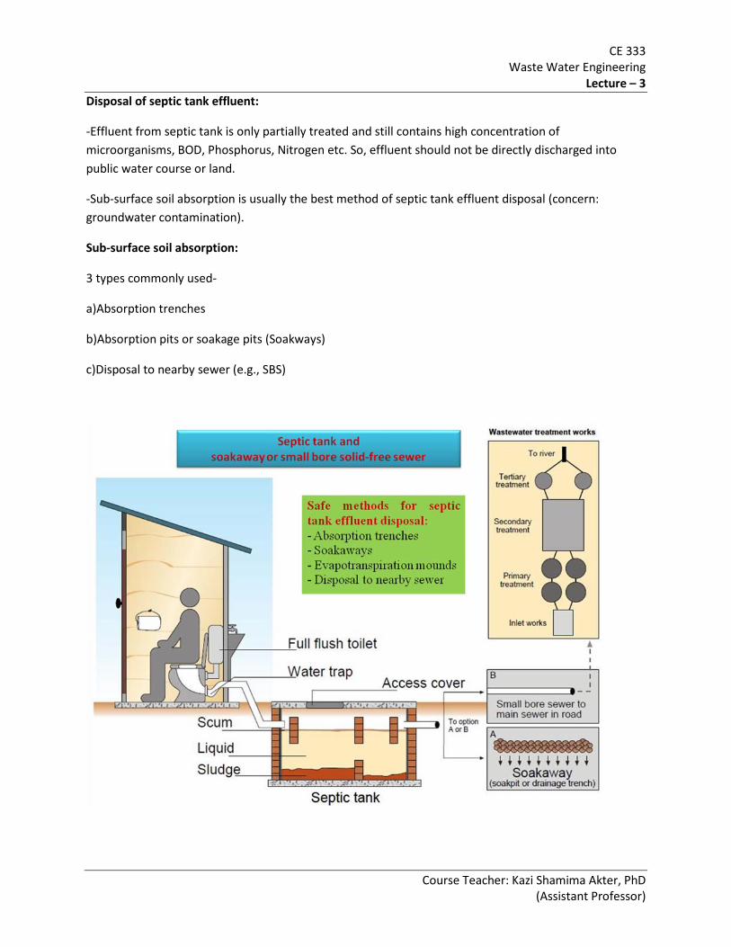
Disposal of septic tank effluent:
-Effluent from septic tank is only partially treated and still contains high concentration of microorganisms, BOD, Phosphorus, Nitrogen etc. So, effluent should not be directly discharged into public water course or land.
-Sub-surface soil absorption is usually the best method of septic tank effluent disposal (concern: groundwater contamination).
Sub-surface soil absorption:
3 types commonly used-
a)Absorption trenches
b)Absorption pits or soakage pits (Soakways)
c)Disposal to nearby sewer (e.g., SBS)

CE 333 Waste Water Engineering
Lecture – 3
Course Teacher: Kazi Shamima Akter, PhD (Assistant Professor)
a) Absorption trenches
-Effluent flows by gravity from septic tank through a closed pipe and distribution box into perforated pipes in trenches. Usually the pipes consist of open-jointed drainage tiles. Bacteria in the soil help to purify the effluent.
b) Soakaway
Waste from the toilet, and generally domestic wastewater, is flushed into the settling chamber where it is retained for at least 24hrs to allow settlement and biological digestion. Partially treated liquids then pass out of the tank and into the subsoil drainage/soakaway system. Digested sludge gradually builds up in the tank and requires eventual removal by tanker.
-Deep excavations used for sub-surface disposal of septic tank effluent.
-Absorption pits are recommended as an alternative when absorption fields or trenches are not practicable and where the topsoil is underlain with porous soil or fine gravel.
-Effluent flows through pit walls made of open jointed bricks, into the surrounding soil.
-Typical diameter of pit 2 to 3.5 m, and depth 3 to 6 m depending upon the amount of wastewater flow, infiltration capacity of soil and level of GWT.
c) Small bore solid-free sewer
-As for the septic tank and soakaway except that the liquid effluent is conveyed by a system of small-diameter pipes to a communal treatment point (which may be off-site treatment works reached either via existing sewerage or by tanker).
Design Problem (Septic Tank and Soakage Pit)
1) Design a septic tank to serve a household of ten persons who produce 90 lpcd of wastewater. The tank is to be desludged in every three years.
2) If the soil is sandy loam with a long-term infiltration rate of about 30 l/m2 day, design a soakage pit for the disposal of effluent from the septic tank of the previous example.
CE 333 Waste Water Engineering
Lecture – 4
Course Teacher: Kazi Shamima Akter, PhD (Assistant Professor)
CE 333 WASTE WATER ENGINEERING
(Credit 3.0, Class Period 3 hours/week)
Design Problems on sanitation technologies
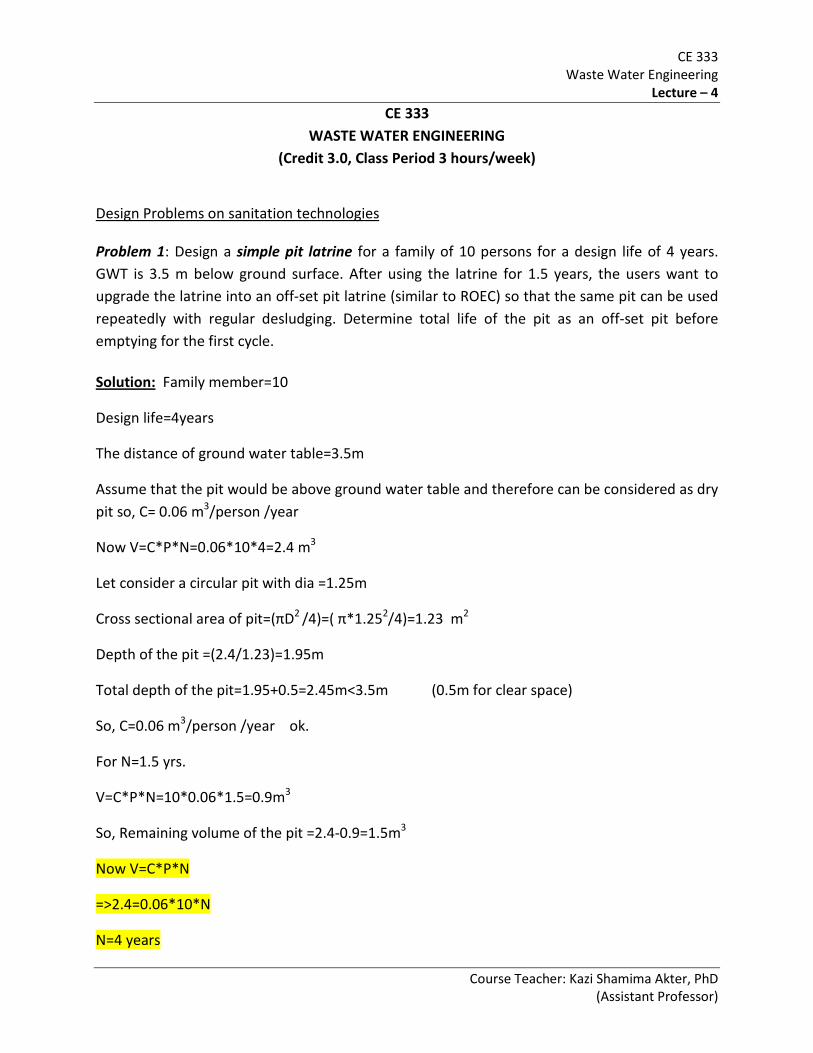
Problem 1: Design a simple pit latrine for a family of 10 persons for a design life of 4 years. GWT is 3.5 m below ground surface. After using the latrine for 1.5 years, the users want to upgrade the latrine into an off-set pit latrine (similar to ROEC) so that the same pit can be used repeatedly with regular desludging. Determine total life of the pit as an off-set pit before emptying for the first cycle.
Solution:
N=4 years
Family member=10
Design life=4years
The distance of ground water table=3.5m
Assume that the pit would be above ground water table and therefore can be considered as dry pit so, C= 0.06 m3/person /year
Now V=C*P*N=0.06*10*4=2.4 m3
Let consider a circular pit with dia =1.25m
Cross sectional area of pit=(πD2 /4)=( π*1.252/4)=1.23 m2
Depth of the pit =(2.4/1.23)=1.95m
Total depth of the pit=1.95+0.5=2.45m<3.5m (0.5m for clear space)
So, C=0.06 m3/person /year ok.
For N=1.5 yrs.
V=C*P*N=10*0.06*1.5=0.9m3
So, Remaining volume of the pit =2.4-0.9=1.5m3
Now V=C*P*N
=>2.4=0.06*10*N

CE 333 Waste Water Engineering
Lecture – 4
Course Teacher: Kazi Shamima Akter, PhD (Assistant Professor)
Problem 2. Design leach pits for a twin offset pit pour – flush latrine for a family of a 7 members for a design period of 2.5 years. The X-section of the pits has to be square. The average waste water flow rate is 12 liters per person per day. The soil is porous silty loam with long – term infiltration rate of 20 liters/m2 /day. In sketch, show the designed latrine and pit arrangement.
Ans :
Given,
Family Members = 7
Design Period, N = 2.5 years
Pit X-section Shape = square
Avg. Wastewater flow rate, q= 12 liter/person/day
Soil type = Porous silty loam
Long term infiltration rate, I = 20 liter/m2/day
Now, Total Waste water flow, Q = 12*7 = 84 l/d
Area required for infiltration, Ai = Q/I m2
= 84/20 = 4.2 m2
Assuming pit width = 1.2 m
So, Pit Volume, Vi = Q*D/4*I = 84*1.2/4*20 = 1.26 m3
Pit Volume with respect to solid storage:
Let assume, solid accumulation rate = 0.04 m3/person/year
N = 2.5 year
So, pit Volume, Vs = C*P*N
=0.04*7*2.5 = 0.7 m3
Now, Case – 1 : single pit pour – flush system :
The effective volume, V = Vi +Vs
CE 333 Waste Water Engineering
Lecture – 4
Course Teacher: Kazi Shamima Akter, PhD (Assistant Professor)
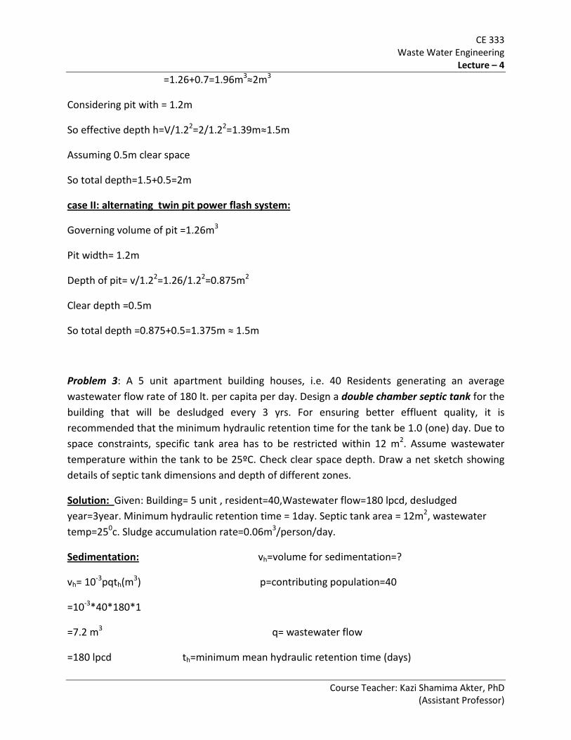
=1.26+0.7=1.96m3≈2m3
Considering pit with = 1.2m
So effective depth h=V/1.22=2/1.22=1.39m≈1.5m
Assuming 0.5m clear space
So total depth=1.5+0.5=2m
case II: alternating twin pit power flash system:
Governing volume of pit =1.26m3
Pit width= 1.2m
Depth of pit= v/1.22=1.26/1.22=0.875m2
Clear depth =0.5m
So total depth =0.875+0.5=1.375m ≈ 1.5m
Problem 3: A 5 unit apartment building houses, i.e. 40 Residents generating an average wastewater flow rate of 180 lt. per capita per day. Design a double chamber septic tank for the building that will be desludged every 3 yrs. For ensuring better effluent quality, it is recommended that the minimum hydraulic retention time for the tank be 1.0 (one) day. Due to space constraints, specific tank area has to be restricted within 12 m2. Assume wastewater temperature within the tank to be 25ºC. Check clear space depth. Draw a net sketch showing details of septic tank dimensions and depth of different zones.
Solution: Given: Building= 5 unit , resident=40,Wastewater flow=180 lpcd, desludged year=3year. Minimum hydraulic retention time = 1day. Septic tank area = 12m2, wastewater temp=250c. Sludge accumulation rate=0.06m3/person/day.
Sedimentation:
=180 lpcd th=minimum mean hydraulic retention time (days)
vh=volume for sedimentation=?
vh= 10-3pqth(m3) p=contributing population=40
=10-3*40*180*1
=7.2 m3 q= wastewater flow

CE 333 Waste Water Engineering
Lecture – 4
Course Teacher: Kazi Shamima Akter, PhD (Assistant Professor)
th =1.5-0.3log(pq) >=0.2day
th =1 day (given)
Digestion : vd= volume for sludge digestion=?
Vd=.5*10-3*ptd (m3) td = time needed for an aerobic digestion
Here td =30(1.035)^35-T (day) settled solids (day)
=30(1.035)35-25 p=40
=42.318 day T=wastewater temp(o c)
So, vd .5*10-3*40*42.318 =25oc
=0.846 m3
Sludge storage: Desludging period=3year
vsl=C*P*N(m3) c=0.06m3/person/year
=0.06*40*3 N<5
=7.2 m3 here c=0.06 m3/person/year
Scum storage:
vsc=0.4vsl(m3)
=0.4*7.2
=2.88 m3
Overall design capacity :
Total septic tank volume, v =vsc+vsl+vd+vh
=2.88+7.20+.846+7.2
=18.126 m3

CE 333 Waste Water Engineering
Lecture – 4
Course Teacher: Kazi Shamima Akter, PhD (Assistant Professor)
Clear space depth:
Scum clear depth =75mm A=area of tank=12 m2
Sludge clear depth =0.82-0.26A>=0.3(m)
=0.82-0.26*12 =-2.3≈0.3m
So, the minimum total clear space=0.075+0.3=0.375m
Depth required for sedimentation = vh/A=7.2/12=0.6m>0.375m
So minimum clear space depth = 0.6m
Now maximum depth of sludge dsl=vcl/A
=7.2/12=0.6m
Maximum depth of scum dsc=vsc/A=2.88/12 =0.24m
So total effective depth =minimum clear space +dsl+dsc
=0.6+0.6+0.24
=1.44m
So the suitable overall dimensions of the septic tank=2m*6m*1.6m
Note: I > length must be 3 times of width
As A=12 so L=A/w so 3w=A/w so 3w2=A and w=√(A/3)=2m
ii> height must be selected in a way that it must cover total volume
here 2*6*1.6=19.2 m3>18.125 m3
for double chamber septic tank:
1st chamber volume =(2/3)*19.2=12.8 m3
2nd chamber volume=(1/3)*19.2=6.4 m3
CE 333 Waste Water Engineering
Lecture – 4
Course Teacher: Kazi Shamima Akter, PhD (Assistant Professor)
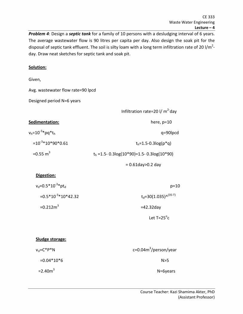
Problem 4: Design a septic tank for a family of 10 persons with a desludging interval of 6 years. The average wastewater flow is 90 litres per capita per day. Also design the soak pit for the disposal of septic tank effluent. The soil is silty loam with a long term infiltration rate of 20 l/m2-day. Draw neat sketches for septic tank and soak pit. Solution:
Given,
Avg. wastewater flow rate=90 lpcd
Designed period N=6 years
Infiltration rate=20 l/ m2-day
Sedimentation: here, p=10
vh=10-3*pq*th q=90lpcd
=10-3*10*90*0.61 th=1.5-0.3log(p*q)
=0.55 m3 th =1.5- 0.3log(10*90)=1.5- 0.3log(10*90)
= 0.61day>0.2 day
vd=0.5*10-3*ptd p=10
=0.5*10-3*10*42.32 td=30(1.035)^(35-T)
=0.212m3 =42.32day
Let T=25oc
Digestion:
vsl=C*P*N c=0.04m3/person/year
=0.04*10*6 N>5
=2.40m3 N=6years
Sludge storage:

CE 333 Waste Water Engineering
Lecture – 4
Course Teacher: Kazi Shamima Akter, PhD (Assistant Professor)
scum storage:
vsc=0.4*vsl
=0.4*2.40
=0.96 m3
overall design capacity:
v=vh+vd+vsl+vsc
=0.55+0.212+2.40+0.96
=4.12 m3
Let area of the tank =3.0 m2
Scum clear depth =0.075m
Sludge clear depth =0.82-0.26A ≥0.3m
=0.82-0.26*3.0 ≥0.3m
= 0.04m
=0.3m
Total clear space =0.3+0.075=0.375m
So clear space depth=0.375m
Total effective depth=clear space depth+dsl+dsc
=0.375+(2.40/3.0)+(0.96/3.0)=1.5m
Clear space depth:
So, suitable internal dimension of septic tank =1m*3.0m*1.5m
Soakage pit design:
=45m2 I=20 l/m2-day
The design is similar to leach pit design (single pit).
Now, Ai =(Q/I) Here,
=(900/20) Q=10*90=900 lt
CE 333 Waste Water Engineering
Lecture – 4
Course Teacher: Kazi Shamima Akter, PhD (Assistant Professor)
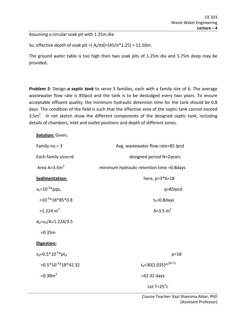
Assuming a circular soak pit with 1.25m dia.
So, effective depth of soak pit =( Ai/πd)=(45/π*1.25) ≈ 11.50m.
The ground water table is too high then two soak pits of 1.25m dia and 5.75m deep may be provided.
Problem 5: Design a septic tank to serve 3 families, each with a family size of 6. The average wastewater flow rate is 85lpcd and the tank is to be desludged every two years. To ensure acceptable effluent quality, the minimum hydraulic detention time for the tank should be 0.8 days. The condition of the field is such that the effective area of the septic tank cannot exceed 3.5m2. In net sketch show the different components of the designed septic tank, including details of chambers, inlet and outlet positions and depth of different zones.
Solution: Given,
Family no.= 3 Avg. wastewater flow rate=85 lpcd
Each family sizes=6 designed period N=2years
Area A=3.5m2 minimum hydraulic retention time =0.8days
Sedimentation: here, p=3*6=18
vh=10-3*pqth q=85lpcd
=10-3*18*85*0.8 th=0.8days
=1.224 m3 A=3.5 m2
dh=vh/A=1.224/3.5
=0.35m
vd=0.5*10-3*ptd p=18
=0.5*10-3*18*42.32 td=30(1.035)^(35-T)
=0.38m3 =42.32 days
Digestion:
Let T=25oc

CE 333 Waste Water Engineering
Lecture – 4
Course Teacher: Kazi Shamima Akter, PhD (Assistant Professor)
Sludge storage
vsl=C*P*N c=0.06m3/person/year
=0.06*18*2 N<5
=2.16m3 p=18
dsl=vsl/A=2.16/35=0.62m N=2years
:
Scum storage:
vsc=0.4*vsl
=0.4*2.16
=0.864 m3
dsc=vsc/A=0.864/3.5=0.25m
Overall design capacity:
v=vh+vd+vsl+vsc
=1.224+0.38+2.16+0.864
=4.628 m3
Scum clear depth =0.075m
Sludge clear depth=0.82-0.26A ≥0.3m
=0.82-0.26*3.5 ≥0.3m
=-0.09m
=0.3m
Total clear space =0.3+0.075=0.375m
But sedimentation depth =0.35m
So clear space depth=0.375m
Clear space depth:
Total effective depth=clear space depth+dsl+dsc

CE 333 Waste Water Engineering
Lecture – 4
Course Teacher: Kazi Shamima Akter, PhD (Assistant Professor)
=0.375+0.62+0.25=1.245m
So suitable internal dimension of septic tank =1m*3.5m*1.35m
Problem 6: Design a septic tank to serve 3 house holds, each with a family size of 6.The waste water flow is 85 lpcd and the tank to be desludged every 3 years. Also Design a soakage pit to dispose a septic tank effluent taking long term infiltration rate of soil to be 40 lt/ m2day Solution:
Given,
House holds= 3 Avg. wastewater flow rate=85 lpcd
Each family sizes=6 designed period N=3years
Infiltration rate=40 lt/ m2day
Sedimentation: here, p=3*6=18
vh=10-3*pq*th q=85lpcd
=10-3*18*85*0.54 th=1.5-0.3log(p*q)
=0.833 m3 th =1.5- 0.3log(18*85)=1.5- 0.3log(18*85)
= 0.54day>0.2 day
vd=0.5*10-3*ptd p=18
=0.5*10-3*18*42.32 td=30(1.035)^(35-T)
=0.38m3 =42.32day
Let T=25oc
Digestion:
vsl=C*P*N c=0.06m3/person/year
Sludge storage:
=0.06*18*3 N<5

CE 333 Waste Water Engineering
Lecture – 4
Course Teacher: Kazi Shamima Akter, PhD (Assistant Professor)
=3.24m3 N=3years
scum storage:
vsc=0.4*vsl
=0.4*3.24
=1.3 m3
overall design capacity:
v=vh+vd+vsl+vsc
=0.833+0.38+2.16+1.3
=4.67 m3
Let area of the tank =3.5 m2
Scum clear depth =0.075m
Sludge clear depth =0.82-0.26A ≥0.3m
=0.82-0.26*3.5 ≥0.3m
= -0.09m
=0.3m
Total clear space =0.3+0.075=0.375m
So clear space depth=0.375m
Total effective depth=clear space depth+dsl+dsc
=0.375+(2.16/3.5)+(1.3/3.5)=1.36m
Clear space depth:
So, suitable internal dimension of septic tank =1m*3.5m*1.5m
Soakage pit design:
Now, Ai =(Q/I) Here,
The design is similar to leach pit design(single pit).
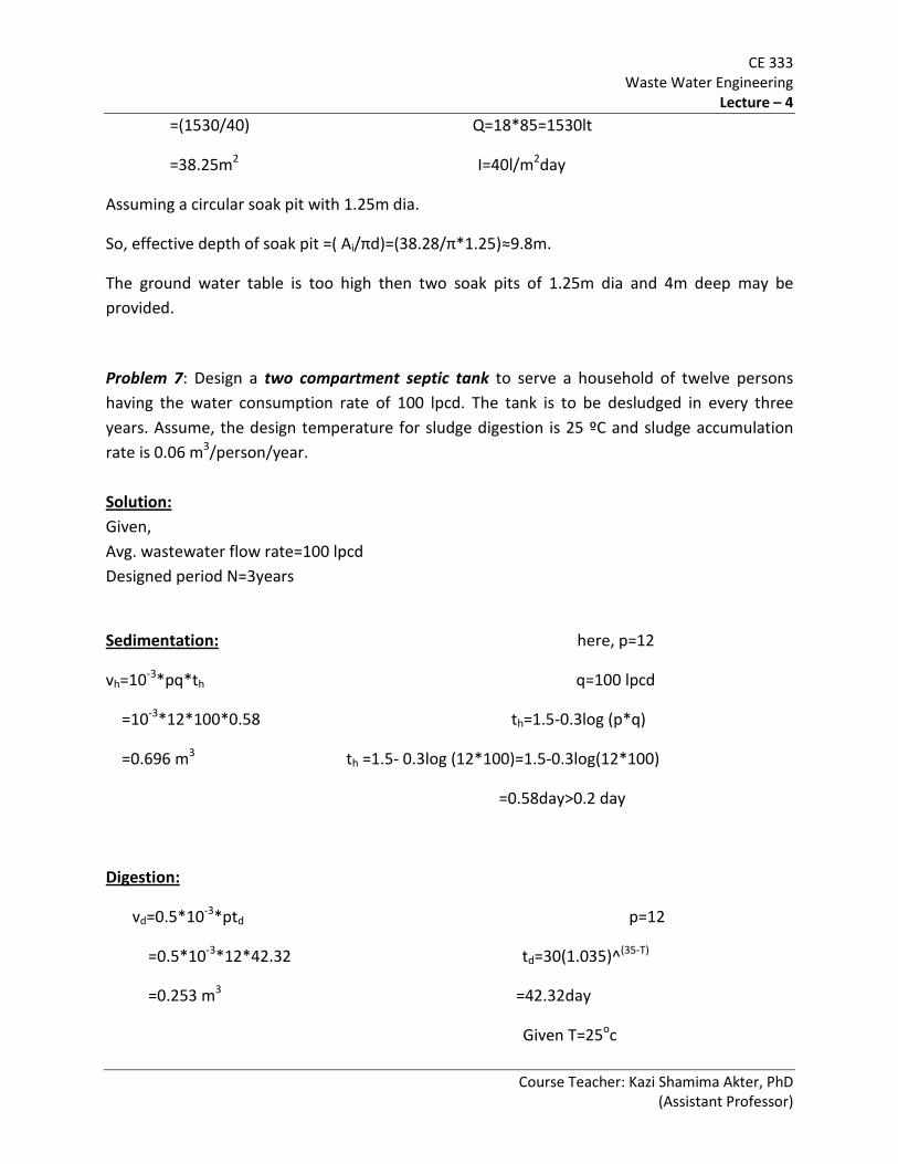
CE 333 Waste Water Engineering
Lecture – 4
Course Teacher: Kazi Shamima Akter, PhD (Assistant Professor)
=(1530/40) Q=18*85=1530lt
=38.25m2 I=40l/m2day
Assuming a circular soak pit with 1.25m dia.
So, effective depth of soak pit =( Ai/πd)=(38.28/π*1.25)≈9.8m.
The ground water table is too high then two soak pits of 1.25m dia and 4m deep may be provided.
Problem 7: Design a two compartment septic tank to serve a household of twelve persons having the water consumption rate of 100 lpcd. The tank is to be desludged in every three years. Assume, the design temperature for sludge digestion is 25 ºC and sludge accumulation rate is 0.06 m3/person/year. Solution: Given, Avg. wastewater flow rate=100 lpcd Designed period N=3years
Sedimentation:
here, p=12
vh=10-3*pq*th q=100 lpcd
=10-3*12*100*0.58 th=1.5-0.3log (p*q)
=0.696 m3 th =1.5- 0.3log (12*100)=1.5-0.3log(12*100)
=0.58day>0.2 day
vd=0.5*10-3*ptd p=12
=0.5*10-3*12*42.32 td=30(1.035)^(35-T)
=0.253 m3 =42.32day
Digestion:
Given T=25oc

CE 333 Waste Water Engineering
Lecture – 4
Course Teacher: Kazi Shamima Akter, PhD (Assistant Professor)
vsl=C*P*N c=0.06m3/person/year
=0.06*12*3 N<5
=2.16m3 N=3years
Sludge storage:
scum storage:
vsc=0.4*vsl
=0.4*2.16
=0.864 m3
overall design capacity:
v=vh+vd+vsl+vsc
=0.696+0.253+2.16+0.864
=3.973 m3
Let area of the tank =3.5 m2
Scum clear depth =0.075m
Sludge clear depth dsc =0.82-0.26A ≥ 0.3m
=0.82-0.26*3.5 ≥0.3m
= -0.09m
=0.3m
Total clear space =0.3+0.075=0.375m
So clear space depth=0.375m
Total effective depth=clear space depth+dsl+dsc
=0.375+(2.16/3.5)+(0.8 64/3.5)=1.239m ≈1.5m
Clear space depth:
So, suitable internal dimension of septic tank =1m*3.5m*1.5m

CE 333 Waste Water Engineering
Lecture – 4
Course Teacher: Kazi Shamima Akter, PhD (Assistant Professor)
Length of First compartment = (2/3)*3.5=2.33m
Length of Second compartment = (1/3)*3.5=1.17m
Fig: 2 Compartments Septic Tank

CE 333 Waste Water Engineering
Lecture – 5
Course Teacher: Kazi Shamima Akter, PhD (Assistant Professor)
CE 333 WASTE WATER ENGINEERING
(Credit 3.0, Class Period 3 hours/week)
CONVENTIONAL SEWARAGE SYSTEM
Basic Functional Elements
(i) the house connections for collection of household or institutional wastewater,
(ii) a network of sewer systems for collection and conveying the wastewater,
(iii) a treatment plant for processing the wastewater, and
(iv) the receiving environment (water or land) for disposal of the treated wastewater.
Important Terms
Wastewater is the liquid waste conveyed by a sewer and may include domestic and industrial discharges as well as storm sewage, infiltration, and inflow.
Domestic (Sanitary) sewage is the liquid waste which originates in the sanitary conveniences, e.g., water closets (wc), urinals, baths, sinks etc. of dwellings, commercial or industrial facilities, and institutions. This is sometimes also referred to as black water.
Industrial wastewater includes the liquid discharges from spent water in different industrial processes such as manufacturing and food processing.
Sullage is the liquid discharge from kitchens, wash basins etc. and excludes discharge from WCs and urinals. Sullage, also known as grey water, is less foul than domestic sewage and can be discharged through open surface drains in unsewered areas.
Storm water is the surface runoff obtained during and immediately after the rainfall, which enters sewers through inlets. Storm water is not as foul as sanitary or industrial sewage and hence can be carried through open drains or channels and disposed of in natural rivers or streams without any treatment.
Infiltration is the water which enters the sewers from the ground through leaks or faulty joints.
Sewer is a pipe or conduit, generally closed, but normally not flowing full, which carries sewage.
Sanitary sewer carries sanitary sewage and is designed to exclude storm sewage, infiltration, and surface inflow. Industrial waste may be carried in sanitary sewers, depending upon its characteristics.
Storm sewer carries storm sewage and any other waste which may be discharged into the streets or onto the surface of the ground.
CE 333 Waste Water Engineering
Lecture – 5
Course Teacher: Kazi Shamima Akter, PhD (Assistant Professor)
Sewerage refers to the entire system of collection, treatment and disposal of sewage through a system of reticulation sewers.
The essential elements of a sewerage system include:
(i) collection and conveyance;
(ii) treatment;
(iii) disposal.
Collection refers to the collection of sewage from different points of generation and conveying sewage to any desired points through a network of sewers.
Sewage treatment includes any process which may be used to favorably modify the characteristics of sewage. Sewage disposal refers to the discharge of liquid wastes to the environment.
Normally, but not always, disposal implies some degree of treatment prior to discharge.
Types of Collection Systems
There are three different sewage collection systems:
1. Separate Sewerage System: In this system sanitary sewage and storm waste are collected and conveyed separately through two different systems
Advantages
Sewers are of smaller sizes;
Only sanitary sewage is treated;
Storm water can be discharged without treatment;
Sewage lifting is less costly because of less volume.
Disadvantages
Two sets of sewers may prove costly;
Smaller sewers may be difficult to clean.
2. Combined Sewerage System: In this system both sanitary sewage and storm water are collected and carried together through a single set of sewers.
Only one set of sewers might prove economical;
Advantages

CE 333 Waste Water Engineering
Lecture – 5
Course Teacher: Kazi Shamima Akter, PhD (Assistant Professor)
Larger sewers are easy to clean;
Strength of sewage diluted with storm water.
Disadvantages
Increased load on treatment plant;
Larger volume requires to be lifted;
Heavy rains may cause overflow and thus create a nuisance;
Storm water is polluted unnecessarily;
More difficult to properly treat the wastewater to high quality standards;
Flow during the dry period may cause difficulties in maintaining minimum flow.
3. Partially Combined or Partially Separate System: In this system only one set of sewers is laid to carry sanitary sewage as well as storm water during low rainfall. During heavy rainfall excess storm water is carried separately e.g., through open drains to natural channels.
Advantages
Sizes of sewers is not very large;
Advantages of both separate and combined systems;
Minimal solids deposition problem;
Problems of storm water discharges from homes are simplified.
Where pumping is required at short intervals.
Disadvantages
Velocity of flow may be low during the dry period;
Increased load on pumps & treatment unit.
Suitable Conditions for a Separate System:
In flat areas a separate system is economical as deep excavations are not required.
When sufficient funds are not available for two sets of sewer systems, only a sanitary sewerage system may be installed.
Where rainfall is not uniform throughout the year a separate system is suitable.
In areas near rivers or streams, only a sanitary system may be installed; storm water may be disposed of into rivers untreated, through open drains.

CE 333 Waste Water Engineering
Lecture – 5
Course Teacher: Kazi Shamima Akter, PhD (Assistant Professor)
In rocky areas where large combined systems may be difficult to install.
If sewers are to be laid before actual development of the area, a separate system is desirable.
Suitable Conditions for Combined System:
Where rainfall is uniform throughout the year, a combined system is economical.
Where pumping is required for both sanitary sewage and storm water.
Where sufficient space is not available for two separate sets of sewer systems.
Types of Sewers
The types and sizes of sewers vary with size of the collection system and the location of the wastewater treatment facilities. The principal types of sewers found in most collection systems are as follows (Figure 4.1):
1. Building Sewers:
also called house connections
used to convey wastewater from the buildings to lateral or branch sewers, or any other sewer except another building sewer.
normally begin outside the building foundation.
2. Lateral or Branch Sewer:
Lateral sewers form the first element of a community sewage collection system and are usually in streets.
They are used to collect sewage from one or more building sewers and convey it to a main sewer.
3. Main Sewer: Main sewers are used to convey sewage from one or more lateral sewers to trunk sewers or to interceptor sewers.
4. Trunk Sewers:
These are large sewers used to convey sewage from main sewers to treatment plants or other disposal facilities or to larger intercepting sewers.
5. Intercepting Sewers:
These are larger sewers that are used to intercept a number of main or trunk sewers and convey the wastewater to treatment or other disposal facilities. An intercepting sewer collects sewage of a particular drainage area of a town.

CE 333 Waste Water Engineering
Lecture – 5
Course Teacher: Kazi Shamima Akter, PhD (Assistant Professor)
6. Outfall Sewer: There are the lengths of main or trunk or interceptor sewers which lie between connections and the final point of disposal or treatment plant.
Figure 4.1: Definition sketch of different types of sewers (peavy et al. 1986)
Design of Sanitary Sewer System
The important objectives of the design of a sanitary sewer system are:
to ensure ease of operation;
to minimize maintenance requirements.
Two major factors to be considered in the design of a sewer system are
the quantity of wastewater flow;
the flow hydraulics.

CE 333 Waste Water Engineering
Lecture – 5
Course Teacher: Kazi Shamima Akter, PhD (Assistant Professor)
Estimation of ‘design flow’ is important in that it ultimately determines the sizes of sewers to be provided. These must be of adequate capacity to handle the waste flow at the end of the design period. Wastewater flows are highly variable and contain floating and suspended solids. Consideration of flow hydraulics in sewer design is, therefore, important in minimizing solids deposition in sewers, thereby minimizing maintenance requirements. Estimation of waste water flows A sanitary sewer system is designed as a separate system, which is intended to receive domestic wastewater, commercial and industrial wastewater and groundwater infiltration.
The quantity of wastewater in sanitary sewer systems is influenced by the following factors:
• population estimate • rate of water supply • type of area served • groundwater infiltration. Population Estimates:
The assessment of the future population is important to determine the quantity of wastewater flow from that area
There is no exact method of predicting the future population in a particular catchment area, nor is there any way of determining the direction that the future development may follow.
Some guiding factors affecting population growth may, however, be considered in estimating future population:
• Past records of the population trends of the locality or similar areas will enable a population growth rate to be determined from which an estimate of the future population can be made.
• A study of the locality may identify areas likely to be preferred for different activities e.g., residential, commercial, industrial or recreational. Such a study may be used to determine the probable future development of an area.
• Government control either by legislation, incentives or a Town Planning Authority may affect the direction and rate of future growth.
• Availability of transport and road systems, power and water supplies will also affect future development of an area.
Evaluation of such factors for a particular region leads to an estimate of the design population, which is

CE 333 Waste Water Engineering
Lecture – 5
Course Teacher: Kazi Shamima Akter, PhD (Assistant Professor)
essential for determining wastewater quantities. Population estimates are often made using the following simple equation:
P = P0 [1 + r]n………………………….. (Eq. 4.1)
Where, P = future population after n years
P0 = present population
r = population growth rate (as decimal)
Relation to water use:
It is fairly common to assume that the average rate of sewage flow is equal to the average rate of water consumption.
But this should be done only after careful consideration of the actual nature of the community.
Such an estimate would be too high for a residential community in an area with hot, dry summers, and too low for a community containing industries, or commercial institutions with private water supplies.
The quantity of sewage will also be affected by factors affecting water use, such as:
• characteristics (economic level) of the population (50-380 lpcd); • metering of water supply; • other factors (e.g., climate, quality, pressure, and conservation programs).
Groundwater infiltration: The presence of a high groundwater table results in leakage into the sewers and in an increase in the quantity of wastewater.
The rate and quantity of infiltration depends on a number of factors:
Depth at which sewer is laid- if the depth at which sewer pipe is laid is below the water-table, infiltration will be more.
Materials of the sewers- sewer materials are stoneware, concrete, cast iron, asbestos-cement, clay, PVC etc. A stoneware sewer pipe will permit more infiltration than cast iron pipes for being less water tight.
Length of sewer below groundwater table;
Nature and types of soils-infiltration of water is more in case of pervious soil than in case of impervious soil.
Types of joints-since groundwater enters the pipes mainly at the joints greater the length of joints more will be infiltration of water.
Workmanship-due to faulty construction of manholes, faulty laying of sewers and faulty house connection, infiltration in sewers will be more.
CE 333 Waste Water Engineering
Lecture – 5
Course Teacher: Kazi Shamima Akter, PhD (Assistant Professor)
Quantity of infiltration can be expressed in one of the following ways:
litres/hectare of area/day
litres/km length of sewer/day
litres/cm (inch) diameter/km length/widely.
Groundwater infiltration rate may vary widely e.g., from 3,000 litres/hectare/day to 50,000 litres/hectare/day depending on age of the sewers, sewer materials, type of area and level of the groundwater table.
Components of design flows: The unit quantities of wastewater for which the sewer sizes have to be designed are called the design flows and consist of the dry weather flow and the wet weather flow.
Also, the wastewater flow is not uniform throughout the day and throughout the year. It varies during the day due to the varying use of water for domestic, commercial and industrial purposes. Variations throughout the year are due to seasonal variation of rainfall and rainfall intensity.
Due to such variations in wastewater flow, the following terms are used:
• Average dry weather flow (ADWF) • Peak dry weather flow (PDWF) • Peak Wet weather flow (PWWF)
ADWF (Average dry weather flow):
Is the average of the daily dry weather flow to the sewer system Not affected by storm infiltration Reflects the wastewater discharges from domestic, industrial and commercial fixtures. PDWF (Peak dry weather flow):
The wastewater flow during the day is not uniform. During normal daily flows, two distinct peaks usually occur - the morning peak and the evening
peak. The ratio of peak to average dry weather flow is termed as the “peak factor” and is a variable and
depends greatly on population size and density. Generally, the ratio will fall as the number of contributor increases. PWWF (Peak Wet weather flow):
Is the maximum flow to be considered in designing the capacity of sewers Is the sum of the maximum peak dry weather flow plus the storm contribution during wet weather
period.

CE 333 Waste Water Engineering
Lecture – 5
Course Teacher: Kazi Shamima Akter, PhD (Assistant Professor)
Storm contribution
is made up of-
direct entry of storm water through flooded manholes,
illegal connections of storm runoff,
by infiltration of groundwater through defective or fractured sewers and fittings.
Sewer:
Most sewers are circular in section. Other shapes such as egg-shaped, rectangular etc. were formerly used, especially in combined sewers. However, due to construction difficulties and high costs these shapes are not used nowadays. Clay, concrete, cast-iron, asbestos and PVC pipes were generally used as sewer pipes. Due to health hazards use of asbestos has been banned. Concrete is somewhat susceptible to corrosion by sulfuric acid from hydrogen sulfide gas generated in sewers or from industrial wastes. It is a serious problem where sewage is strong, stable and very warm. Such conditions hasten the bacterial activities, thus generation of hydrogen sulfide. Where such conditions prevail it is advisable to use clay pipe for diameter smaller than 24 inches and concrete pipes for cast in-situ plastic linings for larger sizes. The smallest sizes are 3-4 inches for house connections.
Figure 4.2: Typical dry and wet weather hydrographs
CE 333 Waste Water Engineering
Lecture – 5
Course Teacher: Kazi Shamima Akter, PhD (Assistant Professor)
Variation in sewage flow:
The flow of domestic sewage varies throughout the day and the year. Flow in storms and combined sewers follow the pattern of runoff from precipitation. Fluctuations are sharp and high. Several mathematical expressions relating maximum flow to average flow have been derived. One proposed by Harmon is:
Qmax/Qavg= (18+√P)/(4+√P) ………………………….. (Eq. 4.2)
where, Qmax = maximum rate of flow of domestic sewage (Peak sewage flow)
Qav = Average rate of flow of domestic sewage
P = Population in thousands
Description of flow Ratio to average
Maximum daily 2.5 to 1
Maximum hourly 3 to 1
Minimum daily 0.67 to 1
Minimum hourly 0.33 to 1
Estimation of Design Flow:
Based on the rational approach, the design flow consists of the sum of the PWDF plus wet weather additive and may be expressed as:
Q = ΣD. d + ΣI. i ………………………….. (Eq. 4.3)
where, ΣD = sum of all dry weather flow components
d = peak dry weather factor
ΣI = basic wet weather additive
i = appropriate infiltration factor
Sewers are usually designed to have a capacity ≥ Q
The average daily dry weather flow is calculated as the sum of the flows from the different types of land use from all individual parts of the catchment.

CE 333 Waste Water Engineering
Lecture – 5
Course Teacher: Kazi Shamima Akter, PhD (Assistant Professor)
ΣD = P. qr + Ac. qc + Ai. qi ………………………….. (Eq. 4.4)
where, P = population
qr = residential discharge rate (say, 100 – 400 lpcd)
Ac = commercial area
qc = commercial discharge rate
(say, 0.25 - .5 l/sec/ha for sub-urban business areas,
but may be up to 8.0 l/sec/ha in high-rise business area)
Ai = industrial area
qi = industrial discharge rate (depends on industry type, e.g., 0.25 – 0.35 l/sec/ha)
d = values vary from 3.0 for small areas and .7 for large areas
ΣI = Ar. K + Ac. K/4 + Ai. K/4 ………………………….. (Eq. 4.5)
where, Ar = residential area
Ac = commercial area
Ai = industrial area
K = ground constant
K = values vary with ground types, higher values for clayey solis and lower values for sandy soils.
K values also vary with density of residential area (e.g., number of connections), type of sewer joints (low values for good joints) and different types of land use (e.g., residential, commercial and industrial). For commercial and industrial, K values are reduced to a quarter.
i = varies from 1.0 for small area to 0.5 for large areas in a manner similar to decrease of rainfall intensity with increasing area
PROBLEM TO SOLVE
Estimate the maximum hourly, average daily and minimum hourly residential sewage flows from an area occupied by 750 people having average per capita sewage flow of 59 gpcd. Consider the length of the sewer and house connections to be 1.3 miles and infiltration to be 30,000 gpd per miles.

CE 333 Waste Water Engineering
Lecture – 6,7
Course Teacher: Kazi Shamima Akter, PhD (Assistant Professor)
CE 333 WASTE WATER ENGINEERING
(Credit 3.0, Class Period 3 hours/week)
The materials used for sewer pipes are required to satisfy the following requirements:
1. Structural strength: Since sewers are normally buried below the ground, highway, etc. they should be strong enough to effectively withstand the stresses to which they may be subjected to.
2. Resistance to corrosion: Sewers should be able to resist corrosion due to corrosive gases, acids or alkaline present in the sewage.
3. Durability: Sewers must be able to resist sudden changes in temperature caused by alternate freezing and thawing.
4. Imperviousness: To prevent infiltration of groundwater or exfiltration of sewage it is essential to have a relatively impervious sewer material.
5. Hardness: To resist erosion, due to abrasive effects of grits, etc.; moving in high speed in sewage pipe, hardness is an essential quality.
6. Uniformity: Uniformity in size and shape is necessary to avoid projections and irregularities at the joints.
7. Proper jointing of pipes: To ensure absolute water tightness. 8. Economy: Economy in cost and construction is an imperative condition.
Self-cleansing Velocity Requirements Sewer flows differ from drinking water flows. Sewage must be removed as soon as possible to prevent septic condition and velocities should not cause erosion. Velocities in excess of 20 fps should be avoided for concrete and whenever possible velocities of 10 fps or less should be used.
► To avoid sewer blockage
► Minimum velocity of 0.6 m/s in a circular sewer
Non-scouring velocity:
► to prevent scouring of sewer material
► 2.5 – 3.0 m/s for concrete sewers
3.0 – 3.5 m/s for vitrified sewers
2.0 – 2.5 m/s for brick sewers

CE 333 Waste Water Engineering
Lecture – 6,7
Course Teacher: Kazi Shamima Akter, PhD (Assistant Professor)
Sewer gradients are affected by the following conditions: ► Slope of the ground: The gradient should as far as possible follow the slope of the ground along the same direction to minimize excavation.
► Gradient should not be steeper that 1 in 20.
► For house connections 1 in 40 to 1 in 80
► Minimum gradient 1 in 100
► Minimum and Maximum velocities: Sewer should be constructed at gradients sufficient to ensure the permissible minimum and maximum velocities.
► Diameter of the sewer and the quantity to be discharged: The bigger sized sewers can carry larger volume of sewage if adequate velocity is provided. In such cases, gradient of the sewer become important.
Hydraulic Formulae used in Designing Sanitary Sewer ► Gravity flow of wastewater
► Chezy’s, Manning’s, Hazen-William formula
► Manning’s Formula: V = 1.486/n R2/3 S1/2
Where,
V is velocity in fps, R=hydraulic radius in ft, S=hydraulic gradient, n=Manning’s roughness co-efficient.
Choice of suitable n is the most important factor in design. The following general suggestion by ASCE is:
1)Vitrified clay, concrete, asbestos-cement and corrugated steel pipe with smooth asphaltic lining, a co-efficient ranging from 0.012 for clear water to 0.015 for strong sewage, 0.013 being a common design value for sanitary sewers.
2) Cast iron pipes, a co-efficient ranging from 0.015 to 0.035 is generally used.
Substituting Q=AV, where A=0.785D2 and hydraulic radius R=D/4=0.25D for a circular sewer flowing full the required diameter is:
D=(2.16Qn/√S)3/8

CE 333 Waste Water Engineering
Lecture – 6,7
Course Teacher: Kazi Shamima Akter, PhD (Assistant Professor)
the required slope is:
S=(Vn/1.486R2/3)2
In most cases the sewer does not flow full. If the depth ratio is known, the cross-sectional area, wetted perimeter, hydraulic radius, velocity and discharge (under this partially flow condition) can be determined.
Sewers flowing partly full
► only full flow condition is allowed during over flow/maximum flow, Usually partial flow condition exists
Let, D = full depth (sewer diameter)
V = velocity of flow during full flow
A= cross sectional area
P = perimeter
Q = average discharge while flowing full
When sewer is flowing partly,
Let, d = flow depth (sewer diameter) v = velocity of flow during partial flow
a= cross sectional area of flow p = wetted perimeter
q = average discharge of partial flow
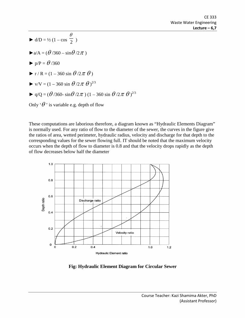
CE 333 Waste Water Engineering
Lecture – 6,7
Course Teacher: Kazi Shamima Akter, PhD (Assistant Professor)
► d/D = ½ (1 – cos 2θ
)
►a/A = (θ /360 – sinθ /2π )
► p/P = θ /360
► r / R = (1 – 360 sin θ /2π θ )
► v/V = (1 – 360 sin θ /2π θ )2/3
► q/Q = (θ /360- sinθ /2π ) (1 – 360 sin θ /2π θ )2/3
Only ‘θ ’ is variable e.g. depth of flow
These computations are laborious therefore, a diagram known as “Hydraulic Elements Diagram” is normally used. For any ratio of flow to the diameter of the sewer, the curves in the figure give the ratios of area, wetted perimeter, hydraulic radius, velocity and discharge for that depth to the corresponding values for the sewer flowing full. IT should be noted that the maximum velocity occurs when the depth of flow to diameter is 0.8 and that the velocity drops rapidly as the depth of flow decreases below half the diameter
Fig: Hydraulic Element Diagram for Circular Sewer

CE 333 Waste Water Engineering
Lecture – 6,7
Course Teacher: Kazi Shamima Akter, PhD (Assistant Professor)
Several important points can be observed from the hydraulic elements diagram
• velocities under full flow conditions and half full conditions are equal, i.e., v =V at both d/D=0.5 and d/D=1;
• the maximum velocity occurs at d/D = 0.81 and is given by v/V= 1.14; • the maximum flow occurs at d/D = 0.94 and is given by q/Q = 1.07.
► Hydraulic element diagram for circular sewers are generally used
► Diagram is useful to, determine all other elements if any one of them is known for a partly filled sewer
► The first step is to determine the area, velocity or discharge for the sewer flowing full and also the ratio of the depth of flow to the diameter of the sewer
► The necessary multiplier for the partly full sewer is then read from the diagram
Problems to Solve:
1. An 18 inch sewer with n=0.013 is laid on a slope of 0.015. a) What is the capacity when flowing half full? b) What will be the velocity when the depth of flow is 4.5 inch.
QUANTITY OF STORM WATER The quantity of storm water that goes to the system depends upon, (a) Area to be drained off (catchment area): larger the catchment site larger the storm water (b) Topography and Nature of the surface: Steep slope produce larger amount of storm water (c) Intensity of the rainfall: If intensity is high, less time duration of rainfall, small evaporation,
thus more storm water (d) Extent of rainfall: greater rainfall greater storm water (e) Antecedent condition: If soils are already wet, then more storm water (f) Obstructions: Obstruction in areas and depressions decrease the quantity of sotrm water to be drained out.
CE 333 Waste Water Engineering
Lecture – 6,7
Course Teacher: Kazi Shamima Akter, PhD (Assistant Professor)
RAINFALL INTENSITY:
► Amount of rainfall in a specific time expressed as mm/hour, cm/hour etc.
► The intensity of a rainfall is the rate at which it is falling
► The duration is the time for which it is falling with that given intensity
► Frequency is the number of times it occurs
► The intensity of rainfall over short periods has been observed to be greater than the average for the whole day.
According to British Ministry of Health –
I (cm/hr) = 76.2 / ( t + 10 ) for t = 5 – 20 minutes
= 101.6 / ( t + 20 ) for t = 20 – 100 minutes
TIME OF CONCENTRATION:
The maximum time taken by water to travel from the extreme catchment boundary to the catchment outlet is known as time of concentraion.
► Bransby-Williams formula:
2.01.0 SA
FLtc =
Where, tc = time of concentration in minutes
F = Factor of proportionality = 58.5 when A in km2 = 92.7 when A in ‘ha’
L = Mainstream length
A = Catchment area
S = Mainstream slope (m/km)
RUN-OFF ESTIMATE:
Rational formula
Peak discharge, Q = FCIA
Where, Q = peak discharge in l/s

CE 333 Waste Water Engineering
Lecture – 6,7
Course Teacher: Kazi Shamima Akter, PhD (Assistant Professor)
F = Factor of proportionality = 27.8 (when A in ha and I in cm/hr) C = run-off coefficient (is a function of area type, soil) I = Rainfall intensity, cm/hr A = Catchment area, ha
Assumption:
► The rainfall is uniform both spatially and temporally
► The duration of the rainfall is equal to the catchment time of concentration
► The recurrence interval of the peak discharge is equal to that of the rainfall intensity
Runoff Coefficient:
Type of surface Run-off coefficient Type of surface Run-off coefficient
Roofs 0.70-0.95 Business D/s area
Neighbourhood
0.70-0.95
0.50-0.70
Asphalt street 0.85-0.90 Residential (Urban)
Parklands
0.30-0.50
0.10-0.25
Cement street 0.80-0.95 Industrial
Heavy Light
0.60-0.90
0.50-0.80
Lawns, sandy soil
2% slope
2-7% slope
> 7% slope
0.05-0.10
0.10-0.15
0.15-0.20
Lawns, heavy soil
2% slope
2-7% slope
> 7% slope
0.13 – 0.17
0.18 –0.22
0.25 - 0.35
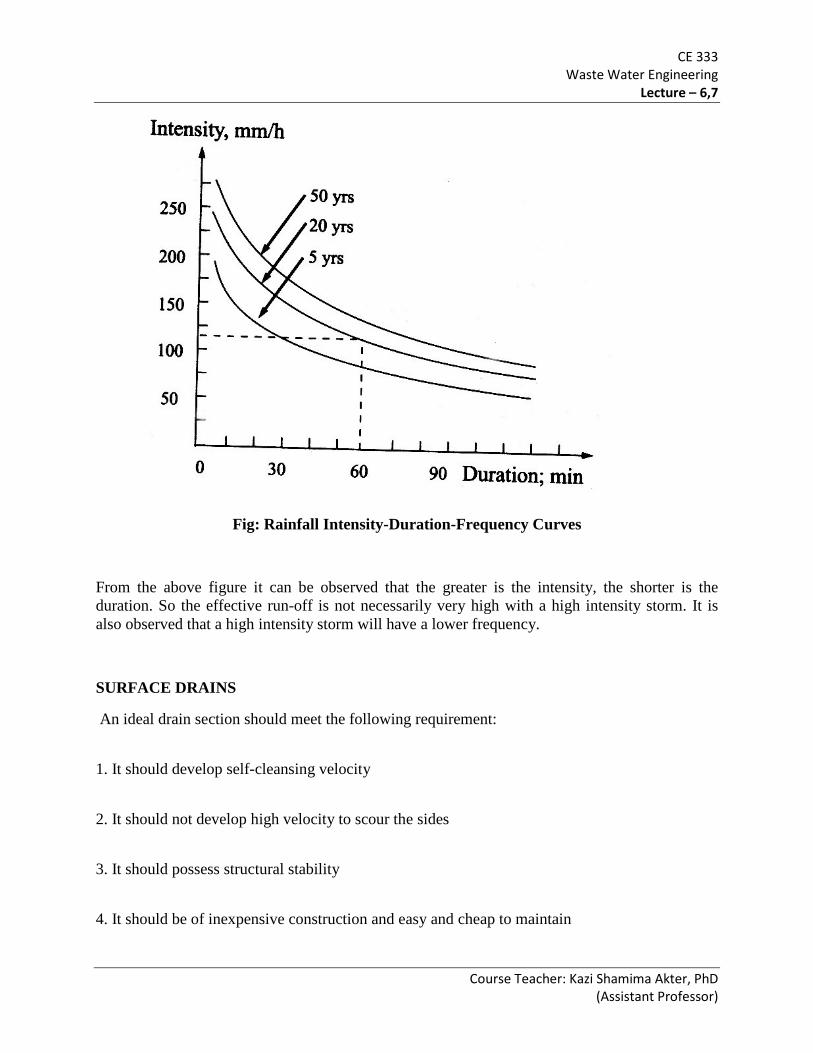
CE 333 Waste Water Engineering
Lecture – 6,7
Course Teacher: Kazi Shamima Akter, PhD (Assistant Professor)
Fig: Rainfall Intensity-Duration-Frequency Curves
From the above figure it can be observed that the greater is the intensity, the shorter is the duration. So the effective run-off is not necessarily very high with a high intensity storm. It is also observed that a high intensity storm will have a lower frequency.
SURFACE DRAINS
An ideal drain section should meet the following requirement:
1. It should develop self-cleansing velocity
2. It should not develop high velocity to scour the sides
3. It should possess structural stability
4. It should be of inexpensive construction and easy and cheap to maintain

CE 333 Waste Water Engineering
Lecture – 6,7
Course Teacher: Kazi Shamima Akter, PhD (Assistant Professor)
5. It should prevent weathering action and wearing action
6. It should have smooth interior surface
7. It should be capable of being cleaned easily
Drain Sections

CE 333 Waste Water Engineering
Lecture – 6,7
Course Teacher: Kazi Shamima Akter, PhD (Assistant Professor)
SMALL BORE SEWERAGE SYSTEM High cost of traditional waterborne sewerage has stimulated interest in alternative low-cost
proposals in order to extend adequate sanitation services to medium and low-income communities.
Small Bore Sewerage (SBS) system is a recent sanitation technology. This system offers all the advantages of conventional waterborne sewerage systems but at a
much lower cost than the conventional ones. SBS system elements There are three basic elements to a small bore sewerage system. These are: • septic tanks; • small bore sewer network; • treatment plant.
Figure: Elements of small bore sewerage system
Basic Difference with Conventional Sewerage System Incorporation of septic tanks within the individual premises as part of the SBS system. The wastewater collected in the septic tank is then transported under gravity through a
network of sewers to a treatment plant comprising a series of stabilization lagoons. In the case of an existing septic tank system the sewer installation commences immediately
downstream of the existing septic tank and new developments must install septic tanks to be able to connect to the SBS system.
Septic tanks Septic tanks or interceptors are required to be installed to achieve the following fundamental functions: • Sedimentation of undissolved, settleable solids in the wastewater thus requiring sufficient retention time. Suspended solids reduction by gravitation and by microbial action is about 18-70%.

CE 333 Waste Water Engineering
Lecture – 6,7
Course Teacher: Kazi Shamima Akter, PhD (Assistant Professor)
• Storage of sludge and scum for at least three to five years or more, thus requiring sufficient volume; • 46-60% reduction of the biochemical oxygen demand (BOD) of the wastewater through anaerobic decomposition of the organic matter contained in the wastewater and this reduction depends on the design and performance of the septic tank; • About 64% attenuation of peak flows, which is a function of the liquid surface area of the tank. Changes in Design Criteria for SBS compared to Conventional Sewerage System The important parameters that bring significant changes in the design criteria of the SBS collection system, due to the presence of septic tanks in individual premises, are- the design flow, sewer sizes, minimum velocity, sewer grades and manholes. Design Flows: wastewater flows 200 lpcd for the design of conventional sewerage systems
–
for SBS system, 40- 80 lpcd with yard tap supplies and form 80-20 lpcd with multiple tap in-house supplies.
Design Flow Peak Factor In SBS system the wastewater flow is attenuated significantly in the septic tank.
–
Design flow peak factor for SBS will be smaller than that of conventional sewerage system.
Design flow peak factor of 2 should be adopted for SBS. Groundwater Infiltration and Surface Inflow Should be considered in conventional sewerage system
–
Can be eliminated in SBS system by using solvent jointed UPVC as sewer materials. Sewer Diameter: The minimum size of sewer most commonly used in the conventional system is 150 mm SBS system can employ a minimum sewer size of as low as 50 mm. As soon as design flows indicate that the sewer will flow more than 60% of full capacity
at full development then the next higher size should be adopted. In developing countries however, where the specialized equipment for cleaning smaller
diameter sewers is not generally available, a minimum diameter of 100 mm may be recommended.
Sewer Gradients: The hydraulic design of circular sewers in conventional sewerage system requires
maintaining a minimum velocity for achieving the self-cleaning action. In the SBS system, it is not necessary to maintain a self-cleansing velocity in the sewer

CE 333 Waste Water Engineering
Lecture – 6,7
Course Teacher: Kazi Shamima Akter, PhD (Assistant Professor)
reticulation system. The grades can be substantially reduced in SBS by reducing the volume of excavation to
a great extent. Manholes and Flushing Points: The SBS system requires less maintenance due to minimal solids content of the
wastewater. Therefore, a fewer number of manholes are installed. Flushing points are used in the system at locations where the manholes would otherwise
exist. These points consist of a 100 mm PVC riser with a removable screw-cap under a concrete cover at the surface to provide access for flushing.
Flushing points are preferable to manholes because they are less costly and can be more tightly sealed to eliminate most infiltration and grit which commonly enter through the lids and walls of manholes.
Technical Advantages The small bore sewerage system has specific technical advantages over the conventional sewerage system as listed below-
•Sewer sizes can be reduced due to attenuation of flow in the septic tank
•Since the wastewater contains minimum solids, self-cleansing velocities are not necessary and hence sewer grades can be substantially reduced.
•Sewer blockages are minimal as septic tanks retain most of the solids content.
•Volume of excavation is considerable reduced because of smaller sewers and lower sewer grades.
•Solid handling at the secondary treatment site is minimum.
•Rapid construction is possible because of lesser volume of excavation and fewer numbers of manholes to be constructed. Successful Application of SBS System: The important aspects that require careful consideration for successful application of SBS system are: • Proper design and construction of interceptor tanks and sewer network; • Regular desludging of interceptor (septic) tanks; • Prohibition of illegal connections to the SBS sewer network. • Proper treatment of collected effluent before final disposal.
CE 333 Waste Water Engineering
Lecture – 6,7
Course Teacher: Kazi Shamima Akter, PhD (Assistant Professor)
SIMPLIFIED SEWERAGE SYSTEM Also called shallow sewerage Low-cost sanitation technology particularly suited to high-density, low-income urban areas
in developing countries. Receives all household wastewater without settlement in solids interceptor tanks or septic
tanks Similar to conventional sewerage, but without any of the latter’s conservative design features Placement:
Small diameter sewers used to convey the sewage are laid at shallow gradients. These sewers are often laid inside housing blocks, where the system is known as condominial
sewerage. They may also be laid outside the housing block, usually under sidewalks rather than in the
middle of the road, as is the case with conventional sewerage.
Design Standards:
Changes in design standards for Simplified Sewerage System compared to the conventional sewerage system are in terms of –
Minimum diameters, Minimum slopes, Minimum depths, and Spacing and location of manholes. Shorter design period
The changes were based on findings of research in hydraulics, satisfactory experience and redundancy, which ultimately led to the development of a lower-cost sewerage system with smaller, flatter and shallower sewers with fewer and simpler manholes.

CE 333 Waste Water Engineering
Lecture – 6,7
Course Teacher: Kazi Shamima Akter, PhD (Assistant Professor)
Figure: Model layout of a small simplified sewerage scheme
Design Principles:
The usual practice for the hydraulic design of circular sewers is to maintain a minimum velocity for achieving the self-cleaning action.
In general a minimum velocity of 0.6 m/sec when flowing full is considered adequate for sanitary sewers.
A critical shear stress (tractive tension) approach instead of minimum velocity theory is used recently in the hydraulic design of sewers.
The critical shear stress of sediment particles is considered as the minimum shear stress necessary for the initiation of motion of the particle.
Its magnitude depends on a number of factors including the densities of the particle and the fluid, the size of the particle and the viscosity of the fluid.
The recent minimum tractive tension approach of hydraulic design is to ensure self-cleansing of sewers by attaining sufficient shear stress on the critical area of the wetted perimeter.
Design: The design of simplified sewerage is based on a minimum tractive tension of 1 N/m2 and a minimum flow depth of 0.2 relative to the sewer diameter. The design slope is thus determined by:
13/6
min 0056.0 −= iQI
where, Imin = minimum sewer slope (m/m)
Qi = initial wastewater flow (liter/sec)

CE 333 Waste Water Engineering
Lecture – 6,7
Course Teacher: Kazi Shamima Akter, PhD (Assistant Professor)
A hydraulic design chart for simplified sewers based on Manning’s equation, simplifies the determination of sewer diameter by relating d/D to Qf/Imin 0.5 and V/Imin 0.5 where Qf is the final flow in m3/sec.
The exact or a nearer value of Qf/Imin0.5 is located in this design chart where d/D does not exceed 0.80. The final velocity Vf is computed from the corresponding V/Imin
0.5 value in the chart.
Suitability: Simplified sewerage systems offer a new cost saving approach primarily based on rational changes in long-standing traditional conservative sewer design standards. One important consideration is that the safety factors, which have been embedded in many design criteria e.g., design flow, minimum diameter, depth etc. need not be the same everywhere in all situations.
• Simplified sewerage could be a viable lower-cost alternative to conventional sewerage systems particularly for the developing countries;
• Design modifications in simplified sewerage are based on sound engineering principles without jeopardizing the level of service;
• Costs could be 30 to 50 % less than conventional sewerage, thus allowing service coverage to be expanded.

CE 333 Waste Water Engineering
Lecture – 6,7
Course Teacher: Kazi Shamima Akter, PhD (Assistant Professor)
Table: Design chart for simplified sewers based on Manning’s equation with n = 0.013, and v in m/s, I in m/m, q in m3/s and the sewer diameter D in mm.

CE 333 Waste Water Engineering
Lecture – 6 (Problems)
Course Teacher: Kazi Shamima Akter, PhD (Assistant Professor)
CE 333 WASTE WATER ENGINEERING
(Credit 3.0, Class Period 3 hours/week)
Problems 1. Estimate the maximum hourly, average daily and minimum hourly residential sewage flows from an area occupied by 750 people having average per capita sewage flow of 59 gpcd. Consider the length of the sewer and house connections to be 1.3 miles and infiltration to be 30,000 gpd per miles. Solution
Description of flow Ratio to average Maximum daily 2.5 to 1 Maximum hourly 3 to 1 Minimum daily 0.67 to 1 Minimum hourly 0.33 to 1 Design Flows: Qav (san) = 100 % of water use (60 –80% for developed country) Qav (design) = Qav (san) + Infiltration + Storm Inflow Qmax (design) = 2.5 Qav (san) + Infiltration + Storm Inflow Qmin (design) = 0.34 Qav (san ) + Infiltration + Storm Inflow

CE 333 Waste Water Engineering
Lecture – 6 (Problems)
Course Teacher: Kazi Shamima Akter, PhD (Assistant Professor)
No of people to be served = 750 Average sanitary sewage flow, Qavg (san) = 750 × 59 = 44250 g/d = 1843.75 g/h Infiltration = 30000 × 1.3 = 39000 g/d = 1625 g/h Qav (daily) (design) = Qav (san) + Infiltration = 44250 + 39000 = 83250 g/d Qmax (hourly) (design) = 3 Qav (san) + Infiltration = 3× 1843.75 + 1625 = 7156.25 g/h Qmin (hourly) (design) = 0.33 Qav (san ) + Infiltration = 0.33× 1843.75 + 1625 = 2233.44 g/h 2. Determine the rate of discharge and discharge velocity in a 30 cm circular sewer with n = 0.013, slope = 0.004 and depth of flow equal to 7.5 cm, using both of the Nomograms and Partial flow diagram, given below.

CE 333 Waste Water Engineering
Lecture – 6 (Problems)
Course Teacher: Kazi Shamima Akter, PhD (Assistant Professor)

CE 333 Waste Water Engineering
Lecture – 6 (Problems)
Course Teacher: Kazi Shamima Akter, PhD (Assistant Professor)
Solution
From the nomograms – for slope =0 .004 (m/m) = 4m/ 1000 m and diameter, D = 30 cm, Discharge, Q = 3570 l/min = 59.5 l/s and Velocity, V = 84 cm/s = 0.84 m/s

CE 333 Waste Water Engineering
Lecture – 6 (Problems)
Course Teacher: Kazi Shamima Akter, PhD (Assistant Professor)
Now, depth ratio, d/D = 7.5 / 30 = 0.25 From the partial flow diagram, q/Q = 0.12
Pipe dia = 30 cm
Slope = 0.004 = 4 m/ 1000 m
Velocity = 84 cm/s = 0.84 m/ s
Q = 3570 l/min = 59.5 l/s

CE 333 Waste Water Engineering
Lecture – 6 (Problems)
Course Teacher: Kazi Shamima Akter, PhD (Assistant Professor)
Therefore, q = 0.12 × 59.5 = 7.14 l/s Again, v = 0.65 × 0.84= 0.55 m/s
3. The surface of a country on which the rain falls is classified as follows:
(i) 25% of area consists of roof (C = 0.80) (ii) 25% of area is paved (C = 0.85) (iii) 15% of area is macadamized road (C = 0.32) (iv) 10% of area is gravel road (C = 0.20) (v) 20% of area is unpaved streets (C = 0.15) The rest of the area is occupied by lawns and gardens for which the value of C is 0.2. Determine the value of C for the entire district. Solution C for entire district = 0.25×0.80+ 0.25×0.85+0.15×0.32+0.10×0.20+0.20×0.15+0.05 ×0.2 = 0.52

CE 333 Waste Water Engineering
Lecture – 6 (Problems)
Course Teacher: Kazi Shamima Akter, PhD (Assistant Professor)
4. If the total area is 12 hectares in previous problem (2) and time of concentration for the area is 15 minutes, what is the runoff of the catchment? Use the formula: I = 76.2 / (t + 10)
F = Factor of proportionality = 27.8 (when A in ha and I in cm/hr)
Solution Peak discharge, Q = FCIA
where, Q = peak discharge in l/s
C = run-off coefficient (is a function of area type, soil) I = Rainfall intensity, cm/hr A = Catchment area, ha
I = 76.2 / (15+10) = 3.05 cm/h
Now, Q= FCIA = 27.8 × 0.52 × 3.05 ×12 = 529 l/s

CE 333 Waste Water Engineering
Lecture – 6 (Problems)
Course Teacher: Kazi Shamima Akter, PhD (Assistant Professor)
5. The equation of the rainfall curve is I = 914.4/ (t + 60), where t in min. The drainage area and the time of concentration are 1.2141 ha and 30 min respectively. Find the maximum runoff if 20% area is hard pavement (C = 0.85), 20% area is roof (C = 0.80), 15% area is gravel road (C = 0.20), 30% area is garden and lawn (C = 0.20) and 15% area is wooded (C = 0.15).
Solution C for the area = 0.20×0.85+ 0.20×0.80+0.15×0.20+0.30×0.20+0.20×0.15+0.15 ×0.2 = 0.44 Rainfall intensity, I = 914.4 / (30 +60) = 10.16 cm/h
Now, Q= FCIA = 27.8 × 0.44 × 10.16×1.2141 = 150.88 l/s = 151 l/s
6. A drainage area, having rain falls during four months of the year only, has an area of 15 ha, with 30 houses/ha. The area has the following surface characteristics:
(i) The average area of the roof is 80 m2/house, with runoff coefficient of 0.9.
(ii) The roads occupy 25% of total area. The main roads are tarred and interior ones are of water bound macadam. Impermeability factor for these roads could be taken as 0.6.

CE 333 Waste Water Engineering
Lecture – 6 (Problems)
Course Teacher: Kazi Shamima Akter, PhD (Assistant Professor)
(iii) The remaining area is open space whose coefficient of runoff may be taken as 0.12.
If the rainfall records show that the intensity of an ordinary rainstorm is 4.5 cm/h, what will be the discharge from this district? Determine the dry weather flow from the area if the population is 300 persons/ha and the rate of water supply is 250 lpcd. Also find the ratio of storm sewage to dry weather flow and indicate the suitability of separate sewerage scheme in the area in preference to combined sewerage scheme.
321
332211
AAACACACAC
++++
=
Solution
For the area of 1 ha, Roof area, A1 = 30 × 80 = 2400 m2 Equivalent roof area, A1 C1 = 2400 × 0.9 = 2160 m2 Road area, A2 = 0.25 × 1 = 0.25 ha = 2500 m2 Equivalent road area, A2 C2 = 2500 × 0.6 = 1500 m2 Open space area, A3 = (10000 – (2400 + 2500) = 5100 m2 Equivalent open space area, A3 C3 = 5100 × 0.12 = 612 m2
Now,
43.010000
61215002160=
++=C
CE 333 Waste Water Engineering
Lecture – 6 (Problems)
Course Teacher: Kazi Shamima Akter, PhD (Assistant Professor)
Q = FCIA = 27.8 ×0.43 × 4.5 × 15 = 807 l/s
Total population to be served = 300 persons / ha = 300 × 15 = 4500 persons
Average daily sewage contribution = 80% of average water supply
= 0.8 × 250 × 4500
= 900000 l/d = 10.42 l/s
Assuming that the sewer is a branch/ lateral sewer, the maximum discharge of dry weather flow,
Q max = 2.5 × 10.42 = 26.05 l/s
Now, ratio of storm sewage to max dry weather flow = 807/26.05 = 31
From this problem, it is clear that if a combined sewer is adopted for the given area, the sewer would carry only 1/ 31 th of total discharge for about 8 months of a year. Thus, a separate sewerage scheme is most suitable for the area given in this problem. However, the modern trend for well planned cities is to adopt combined schemes for their overall merits over separate sewerage schemes.

CE 333 Waste Water Engineering
Lecture – 8
Course Teacher: Kazi Shamima Akter, PhD (Assistant Professor)
CE 333 WASTE WATER ENGINEERING
(Credit 3.0, Class Period 3 hours/week)
Design of a gravity-flow sanitary sewer Design a gravity-flow trunk sanitary sewer for the area shown in the accompanying figure (a). The trunk sewer is to be laid along Peach Avenue starting at 4th Street and ending at 11th Street. Assume that the following design criteria have been developed based on an analysis of local conditions and codes.
1. For design period use the saturation period (time required to reach saturation population).
2. For population densities use the data given in the following table.
3. For residential wastewater flows use the data given in the table above.
4. For commercial and industrial flows (average): a. Commercial – 20 m3/ha. d b. Industrial – 30 m3/ha . d 5. For institutional flows (average): College – 400 m3/d (5330 students × 75 L/student. D) /(1000 L/m3) 6. For infiltration allowance: a. For residential areas, obtain the peak infiltration values from the accompanying figure (b). b. For commercial, industrial and institutional areas, also obtain the peak infiltration values from the figure (b). However, to make into account that the total length of sewers in these areas will generally be less than that in residential areas, use only 50 percent of the actual area to compute the infiltration allowance.

CE 333 Waste Water Engineering
Lecture – 8
Course Teacher: Kazi Shamima Akter, PhD (Assistant Professor)
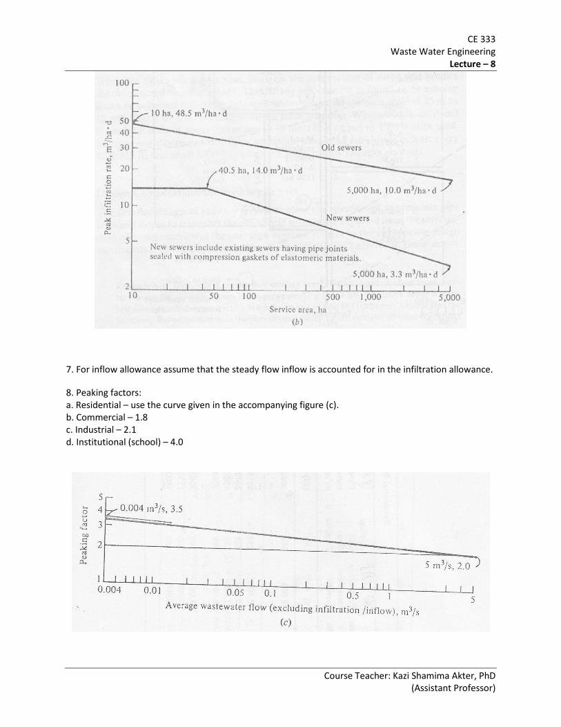
CE 333 Waste Water Engineering
Lecture – 8
Course Teacher: Kazi Shamima Akter, PhD (Assistant Professor)
7. For inflow allowance assume that the steady flow inflow is accounted for in the infiltration allowance.
8. Peaking factors: a. Residential – use the curve given in the accompanying figure (c). b. Commercial – 1.8 c. Industrial – 2.1 d. Institutional (school) – 4.0

CE 333 Waste Water Engineering
Lecture – 8
Course Teacher: Kazi Shamima Akter, PhD (Assistant Professor)
9. For the hydraulic design equation, use the Manning equation with an n value of 0.013. To simplify the computations, use Fig 6.10.
10. Minimum pipe size: The local building code specifies 200 mm (8 in) as the smallest pipe permissible for this situation.
11. Minimum velocity: To prevent the deposition of solids at low waste water flows, use a minimum velocity of 0.75 m/s (2.5 ft/s) during the peak flow conditions.
12. Minimum cover (minimum depth of cover over the top of the sewer): As established by the local community building code, the minimum depth of cover is 2.0 m.
0.12
Diameter (mm) Velocity (m/s)
Slope (m/m)
Discharge (m3/s)

CE 333 Waste Water Engineering
Lecture – 8
Course Teacher: Kazi Shamima Akter, PhD (Assistant Professor)
Solution
1. Lay out the trunk sewer. Draw a line to represent the proposed sewer [figure (a)].
2. Locate and number the manholes. Locate manholes at (1) changes in direction, (2) changes in slope, (3) pipe junctions, (4) upper ends of sewer and (5) intervals from 90 to 120 m or less. Identify each manhole with a number. For the purpose of this problem only the manholes at the major junctions have been numbered [figure (a)]. In actual design, intermediate manholes would be located and numbered.
3. Prepare a sewer design computation table. Based on the experience of numerous engineers, it is found that the best approach for carrying out sewer computations is to use a computation table. The necessary computations for the sanitary sewer shown in figure (a) are presented in the accompanying table.

CE 333 Waste Water Engineering
Lecture – 8
Course Teacher: Kazi Shamima Akter, PhD (Assistant Professor)
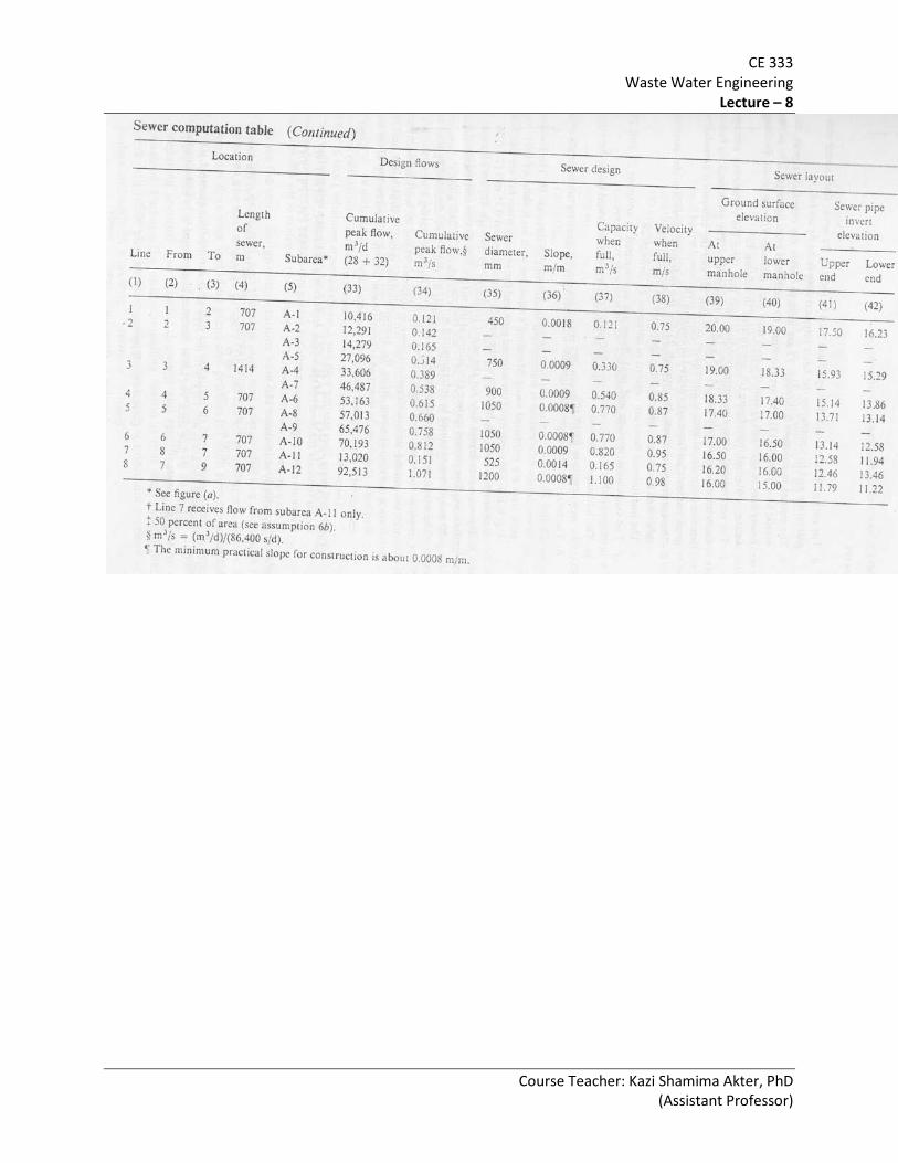
CE 333 Waste Water Engineering
Lecture – 8
Course Teacher: Kazi Shamima Akter, PhD (Assistant Professor)

CE 333 Waste Water Engineering
Lecture – 8
Course Teacher: Kazi Shamima Akter, PhD (Assistant Professor)
0.15 0.12
Diameter (mm) Velocity (m/s)
Slope (m/m)
Discharge (m3/s)
450 mm
0.75 m/s 0.0018 m/m

CE 333 Waste Water Engineering
Lecture – 8
Course Teacher: Kazi Shamima Akter, PhD (Assistant Professor)

CE 333 Waste Water Engineering
Lecture – 8
Course Teacher: Kazi Shamima Akter, PhD (Assistant Professor)

CE 333 Waste Water Engineering
Lecture – 8
Course Teacher: Kazi Shamima Akter, PhD (Assistant Professor)
Sewer
Peaking factors
The effect of daily variations in sewage flow is maximum on domestic and lateral sewers because they receive the flow directly from the source. This effect diminishes gradually as the flow reaches the branches and the mains. Various sewers in a sewer-network are designed not for the average flow rate, but for a flow rate which is higher than the average flow rate by a peaking factor, (i.e., ratio of peak flow to average flow). Such peaking factors are given in the following table.
Peaking factor Domestic sewer 6 Lateral sewer 4 – 6 Branch sewer 3 Main sewer 2.5 Trunk or outfall sewer 2
If flow records are insufficient to establish peaking factors, the curves given in the following figure may be used. These curves have been developed from analysis of records of numerous communities throughout United States.

CE 333 Waste Water Engineering
Lecture – 8
Course Teacher: Kazi Shamima Akter, PhD (Assistant Professor)