the university of nairobieie.uonbi.ac.ke/sites/default/files/cae/engineering/eie/voice and... ·...
TRANSCRIPT

1
THE UNIVERSITY OF NAIROBI
Final year project in the department of Electrical and Information Engineering.
NAME: OMUSE ALEX.
REGISTRATION NUMBER: F17/2150/2004
TITLE: VOICE AND DATA COMMUNICATION OVER POWER LINES.
PROJECT NUMBER: 069
SUPERVISOR: DR CYRUS WEKESA.
EXAMINER: DR. GAKURU MUCHEMI.
A project submitted as a partial fulfilment for the requirement for the award of the degree
of Bachelor of Science in Electrical and Information Engineering.
YEAR OF SUBMISSION: MAY 2009

2
DEDICATION To my parents Josephat Omuse and Susan Omuse, my siblings and M. Florence who have taught
me the beauty of trusting in the power of my dreams through hard work. This work could not be
any better without their encouragement and support. Your lives accomplishments remain to be
my long lasting inspiration.
Thanks mum and dad for making me believe that I can make it and working to see me make it.
To all who desire to experience the benefits of broadband over power lines; this is and idea
whose time has come.
To almighty God for His grace and strength that has made this piece of work a success.

3
ACKNOWLEDGEMENTS Nothing in life is ever successful without the corporate effort of many gifted people who are
willing to network and submit their talent, experience, and passion for a common goal.
We are a sum total of all people we have met and learned from.
This work has given me exposure to the knowledge I have placed in this technical paper.
To all who gave their time and resources. I am a better person because of you. My achievements
are yours also.
Dr. Cyrus Wekesa: project supervisor and guide in developing this manuscript – you are a gift to
many who will read this work. Thank you for conceiving the project and for pursuing me to get
this done.
To all my colleagues and friends who provided insights, encouragement and more important
criticism during proof reading.
Finally my parents, brothers and sisters; no one could be supportive, reliable and encouraging
than them in all my endeavours. I cherish your lives and the part it plays in mine.

4
ABSTRACT Broadband over power lines (BPL) is an emerging technology that carries data over existing
power lines at high frequencies at 2-50 MHz providing high-speed Internet access. Power lines
are designed to carry low frequency electric signals. BPL deployment poses technical and
economic challenges as power lines are not designed to carry data signals at 2-50MHz. Technical
challenges including interference, signal attenuation, noise, lack of standards, and threat to data
security are discussed. Cable modem, DSL, satellite and wireless broadband technologies are
compared with BPL.This paper outlines the technical and economic areas that need to be
addressed before full-scale deployment in the Kenyan context (market).

5
SYMBOLS AND ABBREVIATIONS PLC- Power line carriers BPL-Broadband over power lines CPE-Customer Premise Equipment SNR- Signal to Noise Ration dB- Decibels L/C – Inductive/ Capacitive Loads PVC- Polyvinyl Chloride EHV- Extremely High Voltage EPR- Ethylene-propylene GMF- Geometric mean frequency SCADA- Supervisory Control and Data Analysis KENGEN- Kenya Electricity Generation Company. KPLC- Kenya Power and Lighting Company. MV- Medium Voltage LV- Low voltage GPR- Ground Potential Rise Wi-Fi- Wireless Fidelity OFDM- Orthogonal Frequency Division Multiplexing CSMA- Carrier Sense Multiple Access CA- Collision Avoidance DSSS- Direct Sequence Spread Spectrum CSMA- Carrier Sense Multiple Access ASK-Amplitude Shift Keying Frequency Shift Keying PSK- Phase Shift Keying ISI- Inter-symbol Interference CCK- Communications Commission of Kenya SAC- Significant Acquisition Costs DSL- Digital Subscriber Line ISPs- Internet Service Providers NTU- Network Termination Unit TD- Time Division GMSK- Gaussian Minimum Shift Keying USB - Universal Serial Bus.

6
Table of Contents
DEDICATION ...................................................................................................................................................... 1
ACKNOWLEDGEMENTS ...................................................................................................................................... 3
ABSTRACT .......................................................................................................................................................... 4
SYMBOLS AND ABBREVIATIONS ......................................................................................................................... 5
CHAPTER ONE .................................................................................................................................................... 1
1.0 INTRODUCTION ............................................................................................................................................ 8
CHAPTER TWO .................................................................................................................................................. 10
2.0 LITERATURE REVIEW .................................................................................................................................... 10
2.1 SYSTEM COMPONENTS ......................................................................................................................... 10
2.1.1 MAJOR SYSTEM COMPONENTS EQUIPMENT ............................................................................................................. 10 2.1.1.1 Transmitters & Receivers ....................................................................................................................... 10 2.1.1.2 Hybrids & Filters ..................................................................................................................................... 10 2.1.1.3 Line Tuners ............................................................................................................................................. 10 2.1.1.4 Line Traps ............................................................................................................................................... 11 2.1.1.5 L/C Filters................................................................................................................................................ 12 2.1.2.2.0 Coaxial Cables and Lead‐in Conductor ................................................................................................ 12
2.2.0 COUPLING CAPACITORS ........................................................................................................................................ 13 2.2.1 Line Tuners ................................................................................................................................................ 14
2.2.2 RESONANT‐SINGLE FREQUENCY ............................................................................................................................... 9 2.2.3 BAND‐PASS ........................................................................................................................................................ 10 2.2.5 WIDE‐BAND TRAP ............................................................................................................................................... 11
CHAPTER THREE ................................................................................................................................................ 12
3.0 HOW POWER LINE CARRIERS WORK/OPERATE ............................................................................................ 12
3.1BROADBAND OVER POWERLINES ARCHITECTURE ......................................................................................... 14
3.1 .1 INTRODUCTION ............................................................................................................................................. 14 3.1.2 BPL SYSTEM ARCHITECTURES ................................................................................................................................ 15
3.1.2.1 System 1 ................................................................................................................................................. 15 3.1.2.2 System 2: …………………………………………………. ........................................................................................ 17 3.1.2.3 System 3: ................................................................................................................................................ 18
CHAPTER FOUR ................................................................................................................................................. 20
4.0 TECHNICAL CHALLENGES. ............................................................................................................................ 20
4.1 MINIMUM ‐SECURITY LEVELS: ........................................................................................................................... 20 4.2 DATA ATTENUATION: ....................................................................................................................................... 20 4.2.1 LINE ATTENUATION .............................................................................................................................................. 21
4.2.1.1 Overhead Line ........................................................................................................................................ 21 4.2.1.2 Power Cable ........................................................................................................................................... 23 4.2.2.0 SIGNAL ATTENUATION ........................................................................................................................... 23 4.2.2.1 Alleviation of attenuation ...................................................................................................................... 25 4.2.1.3 Characteristic Impedance ....................................................................................................................... 26
4.3 HIGH COSTS OF RESIDENTIAL APPLIANCES: ....................................................................................................... 27 4.4 LACK OF GLOBAL STANDARDS: .......................................................................................................................... 27 4.5 NOISE: ............................................................................................................................................................... 27
4.5.1 Power line noise ........................................................................................................................................ 28

7
4.5.2 Special Considerations ............................................................................................................................... 32 4.6 INTERFERENCE TO OTHER DATA SIGNALS ......................................................................................................... 32 4.7 THREAT TO DATA SECURITY ............................................................................................................................... 34 4.8 ECONOMIC CHALLENGES .................................................................................................................................. 34
4.8.1 Power line carrier model Economic Analysis ............................................................................................. 35 4.8.2 Model description ...................................................................................................................................... 35 4.8.3 Cable, DSL, and competition...................................................................................................................... 39
4.9.0 KENYAN HOME BROADBAND COMPARISONS ................................................................................................ 39 4.9.1 SAFARICOM BROADBAND ......................................................................................................................... 40 4.9.2 AFRICA ONLINE KENYA. ............................................................................................................................. 41 4.9.3 ACCESS KENYA BROADBAND NETWORK ................................................................................................... 42 4.9.4 ZUKU BROADBAND ................................................................................................................................... 43 4.9.5 ORANGE KENYA BROADBAND NETWORK. ................................................................................................ 44 4.9.5 YU NETWORK BROADBAND ...................................................................................................................... 45 4.9.7 ZAIN BROAD BAND NETWORK ................................................................................................................. 45
CHAPTER FIVE ................................................................................................................................................... 47
5.0 CONCLUSION. ............................................................................................................................................ 47
5.1 RECOMMENTATIONS ................................................................................................................................... 48
5.2 REFERENCES. ............................................................................................................................................... 49
5.3 APPENDICES ................................................................................................................................................ 50
5.3.1APPENDIX I ......................................................................................................................................................... 50 5.3.2. PLC Network: Structure and Topology ..................................................................................................... 50 5.3.3. Topology ................................................................................................................................................... 51 5.3.4 PLC Modulation and Transmission ............................................................................................................ 52 5.3.5 GENERAL DESCRIPTION OF BPL SYSTEMS ................................................................................................. 53 5.3.5 POTENTIAL FUTURE SYSTEMS ................................................................................................................. 588
8
CHAPTER ONE: INTRODUCTION
1.0 INTRODUCTION Power line communications (PLC) uses the energy cables as the communication channel and the
digital data are transferred via energy cables. PLC system is realized between transceivers
modems located on the power lines front-end. Industrial control and home automation have
rapidly been gaining popularity for the past decade. PLC, a new technology that sends data
through existing electric cables alongside electrical current, is set to turn the largest existing
network in the world, the electricity distribution grid, into a data transmission network. PLC will
make it possible to both industrial control and home automation over power lines with
economical and reliable solutions. Long-distance monitoring of alarms and air-conditioning
systems, comfortable control of intelligent household appliances, and off-site reading of
electricity meters will all become feasible-simply via the power grid. BPL injectors, repeaters,
extractors and customer premises equipment (CPE) are the basic devices installed to enable
power line network to provide high-speed Internet access.
Power Line Carrier communication systems consist of a high frequency signal injection over the
electrical power lines. This kind of technology has been used since the 1950 decade in order to
provide signaling and ripple control in High Voltage lines, at transmission level.
In the last years the interest for this technology has suffered a revival because the impressing
increase of the mobile telecommunications has brought a big development in transmission
technologies for this kind of communications. In particular, new modulation technologies used
for wireless communication are especially suitable for PLC communication and make massive
data transmissions possible.
Besides, the opening of the market, the need to integrate Distributed Energy Resources (DER)
and the increase of the power supply demand create a new scenario in which the approach of the
energy distribution system has to change. In such a scenario, the distribution system needs to be
automated in order to give a satisfactory response to the problems that will eventually appear.
Currently PLC communications can be broadband as well as narrowband and both cases present
successful transmissions. Thus, it would be possible to think of an automated distribution
scenario with PLC used as a communication link used for multiple applications.
This paper gives a brief description of the power line carrier operations (this includes the
9
equipments implored in facilitating broad band over power lines) and its viability in the Kenyan
power grid. It also tackles the design issues encountered in broadband over power lines. In
addition it presents a cost comparison and economic benefits of broadband over power lines as
compared with other broad band providers.
Most private dwellings do not have dedicated neither low nor high-speed network cabling
installed, and the labor costs required to install such wiring is often quite high. Power line
communication is an emerging home networking technology that allows consumers to use their
already existing electrical wiring systems to connect home appliances to each other and to the
Internet. Home networks power-line technology can control anything that plugs into an outlet,
including lights, televisions, thermostats, alarms, home automation modules and so on. If there is
the availability of multiple power outlets in every room, the home power line infrastructure
represents an excellent network to share data among intelligent devices, also with high data
transfer rate, up to a few hundreds of Mbps (mega bytes per second).

10
CHAPTER TWO: LITERATURE REVIEW
2.1 SYSTEM COMPONENTS 2.1.1 Major System Components Equipment The major components of a PLC channel includes; transmitters, receivers, line tuners, filters, line
traps, couplers, injectors and extractors. The problem associated with the PLC channel is the
requirement to put the carrier signal onto the high voltage line without damaging the carrier
equipment. Once the signal is on the power line it must be directed in the proper direction in
order for it to be received at the remote line terminal.
2.1.1.1 Transmitters & Receivers The carrier transmitters and receivers are usually mounted in a rack or cabinet in the control
house, and the line tuner is out in the switchyard. This then means there is a large distance
between the equipment and the tuner, and the connection between the two is made using a
coaxial cable. The coaxial cable provides shielding so that noise cannot get into the cable and
cause interference. The coaxial cable is connected to the line tuner which must be mounted at the
base of the coupling capacitor. If there is more than one transmitter involved per terminal the
signal must go through isolation circuits, typically hybrids, before connection to the line tuner.
2.1.1.2 Hybrids & Filters The purpose of the hybrid circuits is to enable the connection of two or more transmitters
together on one coaxial cable without causing inter-modulation distortion due to the signal from
one transmitter affecting the output stages of the other transmitter. Hybrids may also be required
between transmitters and receivers, depending on the application. The hybrid circuits can, of
course, cause large losses in the carrier path and must be used appropriately. High/low-pass and
band-pass networks may also be used, in some applications, to isolate carrier equipment from
each other.
2.1.1.3 Line Tuners The purpose of the line tuner in conjunction with the coupling capacitor is to provide a low
impedance path for the carrier energy to the transmission line and a high impedance path to the

11
power frequency energy. The line tuner/coupling capacitor combination provides a low
impedance path to the power line by forming a series resonant circuit tuned to the carrier
frequency. On the other hand, the capacitance of the coupling capacitor is high impedance to the
power frequency energy. Even though the coupling capacitor has high impedance at power
frequencies, there must be a path to ground in order that the capacitor may do its job. This
function is provided by the drain coil, which is in the base of the coupling capacitor. The drain
coil is designed to be low impedance at the power frequency and because of its inductance it will
have high impedance to the carrier frequency. Thus the combination of the line tuner, coupling
capacitor, and the drain coil provide the necessary tools for coupling the carrier energy to the
transmission line and blocking the power frequency energy. One last function of the line tuner is
to provide matching of impedance between the carrier coaxial cable, usually 50 to 75 ohms, and
the power line which will have an impedance of 150 to 500 ohms.
2.1.1.4 Line Traps The carrier energy on the transmission line must be directed toward the remote line terminal and
not toward the station bus, and it must be isolated from bus impedance variations. This task is
performed by the line trap. The line trap is usually a form of a parallel resonant circuit which is
tuned to the carrier energy frequency. A parallel resonant circuit has high impedance at its tuned
frequency, and it then causes most of the carrier energy to flow toward the remote line terminal.
The coil of the line trap provides a low impedance path for the flow of the power frequency
energy. Since the power flow is rather large at times, the coil used in a line trap must be large in
terms of physical size.
Once the carrier energy is on the power line, any control of the signal has been given over to
nature until it reaches the other end. During the process of traveling to the other end the signal is
attenuated, and also noise from the environment is added to the signal. At the receiving terminal
the signal is decoupled from the power line in much the same way that it was coupled at the
transmitting terminal. The signal is then sent to the receivers in the control house via the coaxial
cable. The application of each of the components of the PLC channel must be considered
carefully in order that the system operates properly. The examination of each of these
components and the details of their application will be discussed in the following sections. Then
an example will be given to show the calculation of PLC performance.

12
2.1.1.5 L/C Filters While not providing the isolation of a hybrid, L/C filters may be used to combine two or more
transmitters. The bandwidth response of the series resonant L/C filter is a function of the L: C
ratio and the frequency to which it is tuned. The insertion loss of the L/C filter is typically
around 2 dB, while the return-loss is only around 10 to 15 dB, depending on application. Another
disadvantage of the L/C filter is the tuning required during installation dictates accurate tuning to
maintain the needed isolation.
Minimum frequency separation of the transmitters should be 25 kHz or 10% of the highest
frequency. These would typically be used where hybrids could not be applied. However, one
should calculate the isolation resulting from use of a resistive hybrid as compared to the LC unit.
A mistermination of a resistive hybrid of anywhere from 25 to 100 ohms will produce a 10 dB or
greater return loss. The advantage here is that one would not have to tune a LC unit.
2.1.2.2.0 Coaxial Cables and Lead-in Conductor Coaxial cables are used to connect the carrier sets (usually in the control house) to the line tuners in the
switchyard. The lead-in conductor is used to connect the line tuner to the coupling capacitor.
2.1.2.2.1 Coaxial Cable Coaxial cable is normally used between a line tuner and a transmitter/receiver or between line
tuners in a long bypass to provide a low impedance connection. Connections between hybrids
also use coaxial cables. The copper braid forms an RF shield which should be grounded at the
transmitter/receiver end only, or at only one end of a bypass. By grounding only one end of the
shield you eliminate problems during faults due to ground potential rise (GPR) conditions. GPR
currents can saturate the impedance-matching transformer and cause a loss of the carrier channel.
The typical coaxial cable is RG-8/U with a center conductor of seven strands of No. 21 copper
wire forming an AWG 12 conductor and a braided shield made of AWG No. 36 copper strands.
The outer covering is a polyvinyl plastic jacket. The characteristic impedance of RG-8/U cable is
52 Ω. The attenuation versus frequency for this cable is shown in Table I for 1,000 feet. The
most common polyvinyl compound used for jacket material is polyvinyl chloride (PVC).
Although this material has excellent chemical and abrasion resistance, better moisture resistance
Material such as black polyethylene (black PE), cross-linked polyethylene Table I - Typical
Attenuation (XL-PE), or chlorinated polyethylene (CPE) are now Characteristics of RG-8/U
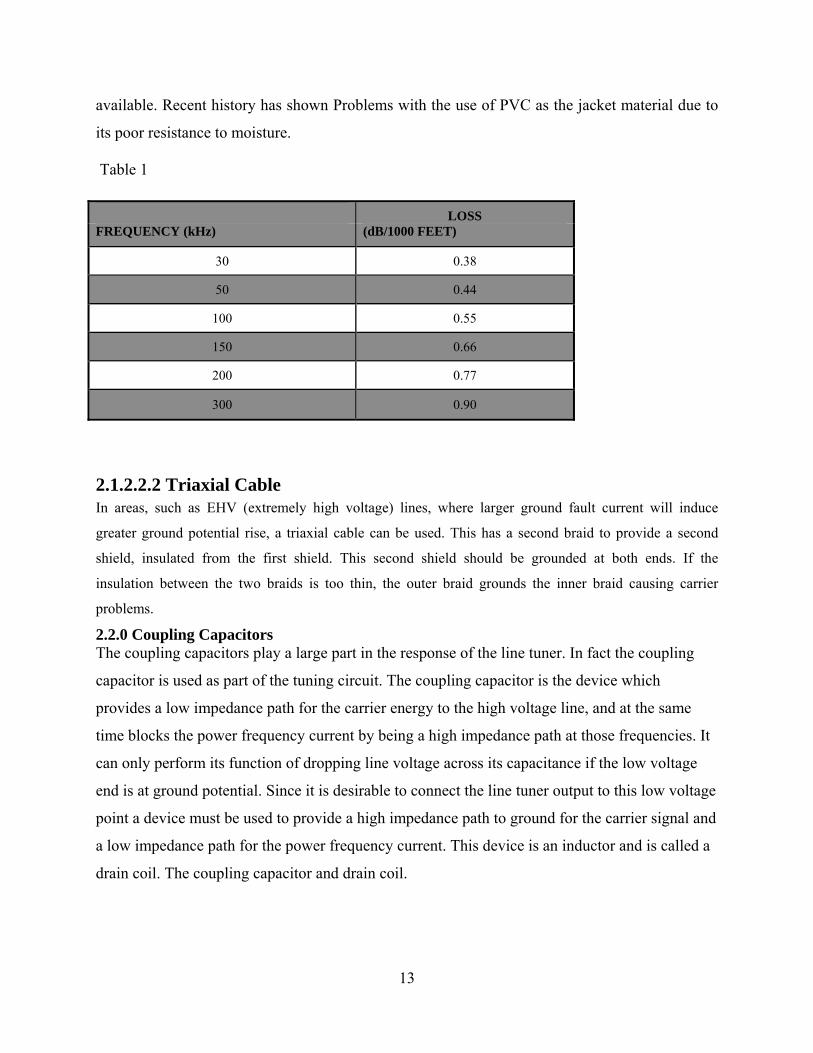
13
available. Recent history has shown Problems with the use of PVC as the jacket material due to
its poor resistance to moisture.
Table 1
LOSS FREQUENCY (kHz) (dB/1000 FEET)
30 0.38
50 0.44
100 0.55
150 0.66
200 0.77
300 0.90
2.1.2.2.2 Triaxial Cable In areas, such as EHV (extremely high voltage) lines, where larger ground fault current will induce
greater ground potential rise, a triaxial cable can be used. This has a second braid to provide a second
shield, insulated from the first shield. This second shield should be grounded at both ends. If the
insulation between the two braids is too thin, the outer braid grounds the inner braid causing carrier
problems.
2.2.0 Coupling Capacitors The coupling capacitors play a large part in the response of the line tuner. In fact the coupling
capacitor is used as part of the tuning circuit. The coupling capacitor is the device which
provides a low impedance path for the carrier energy to the high voltage line, and at the same
time blocks the power frequency current by being a high impedance path at those frequencies. It
can only perform its function of dropping line voltage across its capacitance if the low voltage
end is at ground potential. Since it is desirable to connect the line tuner output to this low voltage
point a device must be used to provide a high impedance path to ground for the carrier signal and
a low impedance path for the power frequency current. This device is an inductor and is called a
drain coil. The coupling capacitor and drain coil.

14
Figure 1: Coupling Capacitor & Drain Coil Combination It is desirable to have the coupling capacitor value as large as possible in order to lower the loss
of carrier energy and keep the bandwidth of the coupling system as wide as possible. However,
due to the high voltage that must be handled and financial budget limitations, the coupling
capacitor values are not as high as one might desire. Technology has enabled suppliers to
continually increase the capacitance of the coupling capacitor for the same price thus improving
performance. Depending on line voltage and capacitor type, the capacitance values in use range
from 0.001 to .05 microfarads.
2.2.1 Line Tuners In conjunction with the coupling capacitor, the line tuner provides a low loss path to the power
line for the carrier signal. There are two basic types of line tuners, resonant and broad-band. The
type used depends on the transmission line and the number of carrier channels to be placed on
the line.
The line tuner should be mounted either in the base of the coupling capacitor, if space is
available, or on the structure that supports the coupling capacitor. The reason is that the lead
between the coupling capacitor and tuner should be as short as possible. Since the coupling
capacitor is part of the filter circuit, the point of connection between it and the line tuner is
generally a high impedance point. Any capacitance to ground in the connecting cable will cause
losses and change the tuning circuit characteristics. This cable is typically a single conductor that
is insulated for high voltage and has a very low shunt capacitance to ground. As mentioned

9
before, coaxial cable should not be used for this connection.
Of the resonant type tuners there are two that are widely used. These are single-frequency and
double-frequency, and are used for carrier systems which have one group or two groups of
channels with narrow bandwidth requirements, respectively.
All line tuners will have a protector unit which is connected from the output lead to ground. This
protector unit must consist of a grounding switch and a protective gap. The gap is present to
protect the tuner from failure during large transients on the power line. These transients have
large amounts of high frequency energy which is passed by the coupling capacitor and are
present at the tuner because the drain coil is high impedance to these frequencies. The grounding
switch is for personnel protection during maintenance. Sometimes the line tuners are supplied
with a drain coil in addition to the one supplied in the coupling capacitor. This drain coil should
not be considered as the primary drainage path. The coupling capacitor must always have a drain
coil and it is considered the primary drainage path for power frequency currents.
2.2.2 Resonant-Single Frequency The single-frequency tuner, shown in Figure 5, has a single inductor and a matching transformer.
The inductor is arranged so that it and the coupling capacitor form a series resonant circuit.
When this circuit is tuned to the carrier frequency it will provide a low impedance path for the
carrier signal to the power line.
The matching transformer provides the impedance match between the 50 and 75 ohm coaxial
Cable and the characteristic impedance of the power line (150 to 500 ohms). This tuner will tune
At one frequency,
Figure 2. Single Frequency Line Tuner thus the name single

10
2.2.3 Band-pass A second form of wide-band coupling is the band-pass tuner. This tuner provides a large
Bandwidth with constant coupling impedance over a band of carrier frequencies. The bandwidth
of the band pass tuner depends on coupling Capacitance, the terminating impedance, and the
square of the geometric mean frequency (GMF), To which the filter is tuned. One should be
careful in applying frequencies too close to the band edges of a band-pass tuner since this area
can change with varying temperature and changes in Standing waves which may be produced on
the power line due to changes in line termination.
When the carrier signal is coupled to the power line it can propagate in two directions, either to
the remote line terminal or into the station bus and onto other lines. If the signal goes into the
station bus much of its energy will be shunted to ground by the bus capacitance. Also some of
this energy would propagate out on other lines thus transmitting the signal to a large portion of
the system. This is undesirable since the same frequency may be used on another line. Because
of these problems, a device is needed to block the energy from going back into the bus and direct
it toward the remote line terminal. This device is of a line trap is that of a parallel LC circuit.
This type of a circuit presents high impedance to the carrier signal at its resonant frequency.
Thus if the parallel LC circuit were placed in series with the transmission line, between the bus
and the coupling capacitor, then the carrier signal would propagate toward the remote terminal.
The line trap must be capable of providing a very low impedance path to the power frequency
current. The inductor in the trap provides this path, and it is designed to carry the large currents
required. Another important function of the line trap is to isolate the carrier signal from changes
in the bus impedance, thus making the carrier circuit more independent of switching conditions.
Line traps come in several versions just as the tuners do, and these types are single-frequency,
double-frequency, and band-pass. Usually the trap used is the same type as the line tuner, that is,
if the tuner is a single-frequency type, the trap will also be a single-frequency type. However, it
is not absolutely necessary that the line trap be of the same type as the tuner. As an example
wide-band traps could be used at all times. The question of economics and blocking impedance
will dictate the type of trap to be applied.Note that both the single- and double-frequency traps
have a rather sharp resonance peak which provides a 7 to 10 kilo ohms blocking impedance at
one given frequency. On the other hand, the wide-band trap will block a large bandwidth of
frequencies but its blocking impedance is low, on the order of 0.5 kilo ohms. Therefore, the

11
resonant traps will have less loss than the wide-band type.
The trap can have both a low-Q and a high-Q setting. The low-Q setting of the trap provides
lower blocking impedance, but has a wider bandwidth. This setting can thus be used to couple
two or more very close frequencies to the line. The high-Q setting of the trap provides the normal
high blocking impedance, but it has a very narrow bandwidth which may be very susceptible to
variations in the bus impedance. The bus is capacitive at carrier frequencies and it can form a
series resonant circuit with the inductance of the trap, and this then can create a low impedance
path to ground. Power transformers on the line behind the trap have been known to affect the trap
and change the tuning characteristic. These types of effects can be detected by comparing the
received signal at the other end for two conditions. The first level is measured with the
disconnect switch between the trap and the bus open. The second level is with the line normal
(disconnect closed). If the signal level changes by a large amount between these two conditions
and you are certain the trap is tuned properly, then the low-Q setting should be selected since the
station impedance will have less effect on the trap tuning. The channel losses will be a little
higher, but the channel will be less affected by switching conditions.
Note that not all traps have the low-Q option, and you should check with the manufacturer of the
trap.
2.2.5 Wide-band trap When applying a wide band trap, two things must be decided, that is, bandwidth requirements
and how much blocking impedance is needed. Both these factors will greatly affect the cost of
the trap. The blocking impedance and bandwidth are directly related to the required inductance
which is a large part of the cost. Also it is suggested that frequencies not be used that are near the
band edge of the trap because the tuning in that area may change with system conditions.

12
CHAPTER THREE: OPERATION PRINCIPLE
3.0 HOW POWER LINE CARRIERS WORK/OPERATE
Fig 3.Distribution access
As shown in the figure data from the Internet can enter (or leave) at the substation level, where
specialized equipment generates the data signals that are coupled (physically attached) onto the
MV(medium voltage) wire. At the other end, the consumer connects their computer(s) to a PLC
modem—the Customer Premises Equipment (CPE)—which plugs into a power socket.
In the BPL basic architecture, signals are injected into the electric grid from a head end on the
medium- or low-voltage lines at a substation. To back haul the signal to the head end from the
substation, fiber or wireless connections are used. The signals traverse the grid network over
medium-voltage and low-voltage lines to the home or business of the end user. Links between
the medium-and low-voltage lines are facilitated by channeling signals either through the
transformers or by bypassing the transformer via bridges.
In order to reach the end users, there are two alternatives that can be used. Vendors such as
Amperion provide interconnect with end users via wireless connections at the transformer. It
must be a Wi-Fi (802.11b for now) connection at two points: at a service injection point for
medium voltage (11/33 kV) line, and at the customer drop. Repeaters and extractors along the

13
line boost the signal and provide customer access via Wi-Fi. Line-mounted extractors can be
powered through induction (requires >70A line) and have an internal Wi-Fi antenna. Pole-
mounted and enclosure-mounted (for areas with underground wires) installations require a
transformer and external antenna. One clever touch is an antenna hidden inside a light pole. The
solution uses off-the-shelf Wi-Fi equipment as customer premise equipment (CPE). Others,
such as Mitsubishi, offer wire line connections, where users can plug a BPL modem into any
electrical outlet. They then connect their PC to the BPL modem with an Ethernet or USB cable
to finish the connection. The process is similar to that required by users to connect to a cable-
based Internet service. BPL is able to transport data, voice and video at broadband speeds for
end-user customer connections.
There are numerous BPL vendors in the marketplace at other parts of the world, but in Kenya
the leading vendors in terms of installs are ABB Company who have been given the tender to
supply and install supervisory Control and Data Acquisition (SCADA) system to facilitate
automated meter reading, faulty detection and detection of equipment being interfered with
among other online uses. In addition, Mitsubishi Electric has several installations in other
countries, for instance in the United States of America and they use a bridging technology to
bypass the transformer. It is the largest company in the BPL equipment market, with a global
reach, and it bears watching as the market develops.
There is a wide range of energy companies in Kenya that have shown interest in BPL or are
currently using BPL on a trial basis. These include The Kenya Power and Lighting Company,
Kenya Electricity Generating Company (KENGEN) among others. Given the resent
developments in technology many energy utility companies will go commercial by 2030 as per
vision 2030 which encompasses rural electrification. These utility companies mainly KPLC will
serve over 15 million potential BPL customers (by then) out of the 30 million plus population
who currently majorly rely on electricity as the source of energy.

14
3.1BROADBAND OVER POWERLINES ARCHITECTURE
3.1 .1 INTRODUCTION Access BPL equipment consists of injectors (also known as concentrators), repeaters, and
extractors. BPL injectors are tied to the Internet backbone via fiber or Transmission lines and
interface to the Medium Voltage (MV) power lines feeding the BPL service area. MV power
lines may be overhead on utility poles or underground in buried conduit. Overhead wiring is
attached to utility poles that are typically ten meters above the ground. Three phase wiring
generally comprises an MV distribution circuit running from a substation, and these wires may
be physically oriented on the utility pole in a number of configurations (for instance horizontal,
vertical, or triangular). This physical orientation may change from one pole to the next. One or
more phase lines may branch out from the three phase lines to serve a number of customers. A
grounded neutral conductor is generally located below the phase conductors and runs between
distribution transformers that provide Low Voltage (LV) electric power for customer use. In
theory, BPL signals may be injected onto MV power lines between two phase conductors,
between a phase conductor and the neutral conductor, or onto a single phase or neutral
conductor.
Extractors provide the interface between the MV power lines carrying BPL signals and the
households within the service area. BPL extractors are usually located at each LV distribution
transformer feeding a group of homes. Some extractors boost BPL signal strength sufficiently to
allow transmission through LV transformers and others relay the BPL signal around the
transformers via couplers on the proximate MV and LV power lines. Other kinds of extractors
interface with non-BPL devices (for instance Wi-Fi) that extend the BPL network to the
customers’ premises.
For long runs of MV power lines, signal attenuation or distortion through the power line may
lead BPL service providers to employ repeaters to maintain the required BPL signal strength and
fidelity. Figure 4-1 illustrates the basic BPL system, which can be deployed in cell-like fashion
over a large area served by existing MV power lines. MV lines, typically carrying 11kv to 33 kv,
bring power from an electrical substation to a residential neighborhood. Low Voltage
distribution transformers step down the line voltage to 230/110 volts for residential use.

15
Access BPL
Modem + PC
Figure 4-1: Basic BPL System
3.1.2 BPL System Architectures There are three different network architectures used for BPL equipment installation. These
architectures are described below.
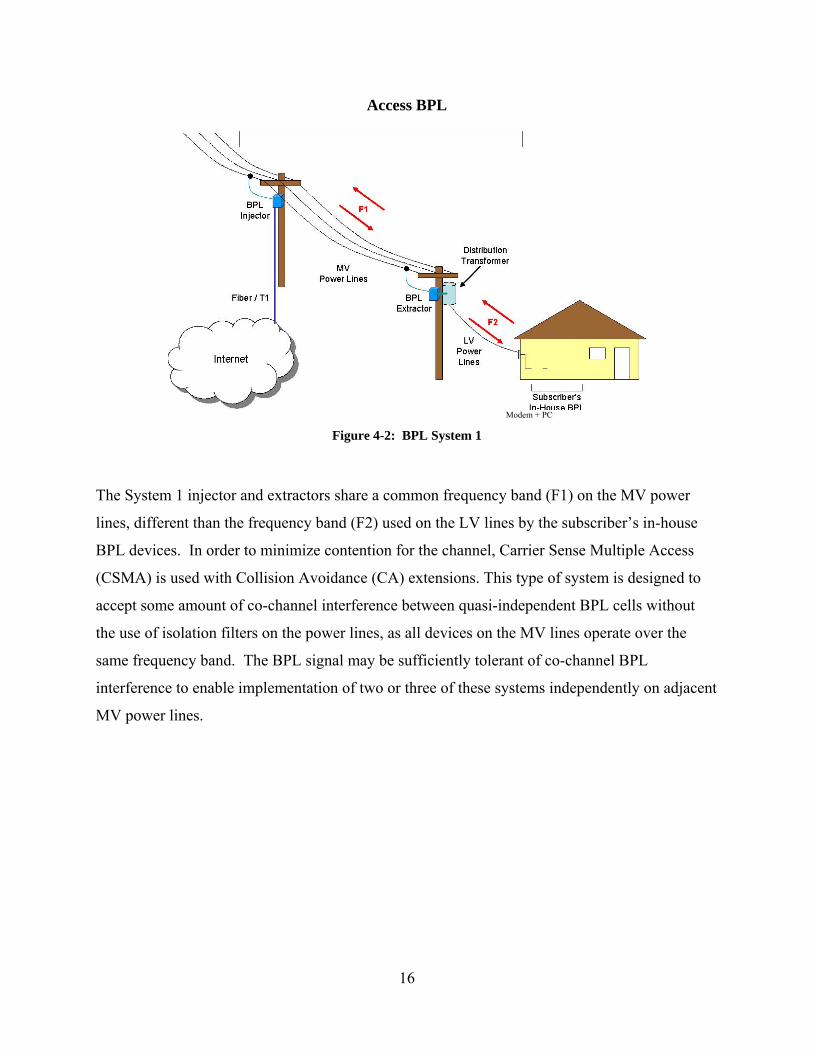
3.1.2.1 System 1 System 1 (see Figure 4-2) employs Orthogonal Frequency Division Multiplexing (OFDM) to
distribute the BPL signal over a wide bandwidth using many narrow-band sub-carriers. At the
BPL injector, data from the Internet backbone is converted into the OFDM signal format and is
then coupled onto one phase of the MV power line. An injector also converts BPL signals on the
MV power lines to the format used at the Internet backbone connection. The two-way data are
transferred to and from the LV lines, each feeding a cluster of homes, using BPL extractors to
bypass the LV distribution transformers. The extractor routes data and converts between access
and in-house BPL signal formats. The subscribers access this BPL signal using in-house BPL
devices. To span large distances between a BPL injector and the extractors it serves, repeaters
may be employed.
16
Access BPL
Modem + PC
Figure 4-2: BPL System 1
The System 1 injector and extractors share a common frequency band (F1) on the MV power
lines, different than the frequency band (F2) used on the LV lines by the subscriber’s in-house
BPL devices. In order to minimize contention for the channel, Carrier Sense Multiple Access
(CSMA) is used with Collision Avoidance (CA) extensions. This type of system is designed to
accept some amount of co-channel interference between quasi-independent BPL cells without
the use of isolation filters on the power lines, as all devices on the MV lines operate over the
same frequency band. The BPL signal may be sufficiently tolerant of co-channel BPL
interference to enable implementation of two or three of these systems independently on adjacent
MV power lines.
17
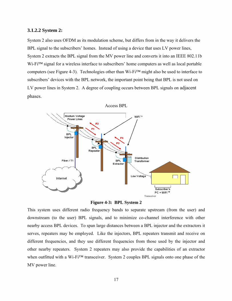
3.1.2.2 System 2:
System 2 also uses OFDM as its modulation scheme, but differs from in the way it delivers the
BPL signal to the subscribers’ homes. Instead of using a device that uses LV power lines,
System 2 extracts the BPL signal from the MV power line and converts it into an IEEE 802.11b
Wi-Fi™ signal for a wireless interface to subscribers’ home computers as well as local portable
computers (see Figure 4-3). Technologies other than Wi-Fi™ might also be used to interface to
subscribers’ devices with the BPL network, the important point being that BPL is not used on
LV power lines in System 2. A degree of coupling occurs between BPL signals on adjacent
phases.
Access BPL
Transceiver
Figure 4-3: BPL System 2 This system uses different radio frequency bands to separate upstream (from the user) and
downstream (to the user) BPL signals, and to minimize co-channel interference with other
nearby access BPL devices. To span large distances between a BPL injector and the extractors it
serves, repeaters may be employed. Like the injectors, BPL repeaters transmit and receive on
different frequencies, and they use different frequencies from those used by the injector and
other nearby repeaters. System 2 repeaters may also provide the capabilities of an extractor
when outfitted with a Wi-Fi™ transceiver. System 2 couples BPL signals onto one phase of the
MV power line.

18
3.1.2.3 System 3:
System 3 uses Direct Sequence Spread Spectrum (DSSS) to transmit the BPL data over the MV
power lines. All users within a BPL cell share a common frequency band. In order to minimize
contention for the channel, Carrier Sense Multiple Access (CSMA) is used. Like System 1, this
type of system is designed to accept some amount of co-channel interference between cells, as all
devices operate over the same frequency band. At one trial deployment of the System 3
architecture, the BPL service provider independently implements two phases of the same run of
three phase power lines.
Each cell in System 3 (see Figure 4-4) is comprised of a concentrator (injector) that provides an
interface to a Transmission line or fiber link to the Internet backbone, a number of repeaters
(extractors) to make up for signal losses in the electric power line and through the distribution
transformers feeding clusters of dwellings, and customer premises BPL equipment, used to
bridge between the user’s computer and the electrical wiring carrying the BPL signal. Adjacent
cells typically overlap and the customers’ BPL terminals and repeaters are able to communicate
with the concentrator that affords the best communication path at any time.

19
Access BPL
Modem + PC
Figure 4-4: BPL System 3
System 3 couples the BPL signal onto the power line using a pair of couplers on a phase and
neutral line.

20
CHAPTER FOUR: TECHNICAL (DESIGN) CHALLENGES
4.0 TECHNICAL CHALLENGES.
Unfortunately, there are some challenges that have to be overcome and some aspects that have to
be taken into account to realize a successful data communication. They are listed in the
following:
4.1 MINIMUM -SECURITY LEVELS: Power lines do not necessarily provide a secure media due to the faults that occur in the power
system network.
4.2 DATA ATTENUATION: Attenuation is the loss of power that a high frequency signal suffers through the transmission.
Due to the presence of numerous elements on a power line network, Data attenuation is likely to
be an issue affecting the ability of broadband over power lines to compete with other broadband
providers. The graph below shows a techno-economic analysis of Broadband over power lines
with effects of attenuation with distance.

21
4.2.1 Line attenuation
4.2.1.1 Overhead Line The relative efficiency of power- and carrier-frequency transmission also differs significantly.
Many factors are involved in the carrier signal losses on a transmission line. The primary factors
are: carrier frequency, line construction, phase conductor size and material, shield wire size and
material, type and location of transpositions, weather conditions, earth conductivity, and
insulator leakage. Line losses will increase as the frequency goes higher. This is primarily
because of the fact that most losses are due to shunt capacitance which becomes lower
impedance at higher frequencies. Conductor losses also play a role in increasing attenuation, due
to the increased skin effect which means that less conductor area is available to higher frequency
current.
Weather conditions play a large role in the changing of the line attenuation with time. Losses
will increase for all inclement weather conditions. The worst offender, however, is when heavy
frost is formed on the line. Because of the skin effect, the carrier signal tries to propagate on the
ice instead of the conductor. The attenuation changes depending on frequency. Also attenuation
is increased on transmission lines due to the presence of contaminants on the insulators. The
contaminants will have a much larger effect when it is raining than when the line is dry. The
worse situation here is a light rain where the contaminants do not get washed off the insulators.
Line losses will change due to changing earth conductivity. This is particularly true when the
coupling method relies on modes of propagation. For instance Transmission Line Losses which
require the earth as a return path. These kinds of earth conductivity changes come about by
extreme changes in soil moisture. This may or may not be a concern, depending on the type of
soil that is present. As indicated in Table II, foul-weather losses are estimated by adding 25
percent to the values shown for lines 230 kV or higher and 50 percent for lines less than 230 kV.
The corrections for transpositions in the line are shown in Table III. The type of coupling will
affect the overall line loss and Table IV shows the coupling correction factors for the most
popular coupling for Foul-Weather arrangements. Coupling types are generally described on the
basis of a single circuit line of flat construction. First, there is the single phase to ground types,
that is, the carrier signal is coupled between one phase and ground. Of these types the most
popular is center phase to ground. Next there are the phase-to-phase coupling types. In this type

22
the carrier signal is coupled between two phases of the power line and the energy in the two
phases are out of phase with each other, in most cases. The last form of coupling is called mode
1 and is a special case of coupling to all three phases. In mode 1 coupling, current is in phase on
the two outside phases and returns through the center phase. Mode 1 coupling is the most
efficient means of coupling the carrier to the power line. Overall system losses will be discussed
later by using an example. For a more extensive explanation of mode 1 coupling see the section
titled “Modal Analysis.”
Table II – Correction Factors
Table III – Transposition Losses in dB for 345 kV & Higher
Number <10 Mi. * >100 Mi. *
1 0 6
2-4 0 8 5 or more
0 10
Table IV – Coupling Correction Factors
Type of Coupling* >50 mi. Line
Mode 1 0 Center-to-Outer Phase 2
Center-to-Ground Al or Cu Ground
Wire 3
Steel Ground Wire 6 Outer-to-Outer (In Phase) 5
Unused phases assumed to be at reference ground.

23
4.2.1.2 Power Cable
Line attenuation in a power cable is larger than those seen in overhead phase wires. The specific
loss encountered with a particular cable will depend on its construction and the method of
coupling. Two types found are single-conductors self-contained and single or three-conductor
pipe-type cables. Skid wires wrapped around the conductors, which protect the conductors
during insertion, will affect the attenuation of the carrier signal as well. Mutual coupling between
phases in a three-conductor pipe-type cable will vary with frequency. Also, if the cable is three
single-conductor pipe type cables, mutual coupling will not exist. Phase-to-Ground Attenuation
on a designing the system since this will affect the 132 kV Pipe-Type Cable efficiency of
coupling and during faults will adversely affect the channel performance. That is if the fault is on
the coupled phase, no signal will get through the fault since there is no mutual coupling to the
other phases. The characteristic impedance of power cables (underground) vary greatly from
those for overhead lines. Generally speaking, the power cables will have characteristic
impedance between 10 to 60 Ω.
4.2.2.0 Signal Attenuation Power line network is the largest network with 95% of the worldwide coverage. The signal
strength gets reduced as BPL signals travel at high frequency over the long power lines. This is
also due to the varied characteristics of the MV lines, LV lines and in home cables causing signal
attenuation. Various factors affect signal attenuation for access BPL including types of cables
used, injection point of BPL signal and injection phase used to inject BPL signal. Signal
attenuation occurs more easily on the broadband (MHz) frequency than the narrowband (KHz)
frequency. Distribution network simulations carried out on access BPL indicate that signal
attenuation increases with the increase in frequency. These simulations also indicate that signal
attenuation increases with the increase in length of power lines. BPL signals over aerial cables
experience less attenuation due to lack of dielectric loss than the underground cables. This is also
due to the different cable parameters such as total radius, etc.
Attenuation depends on the types of coating of power lines with insulation material, such as
polyvinyl chloride (PVC) and oilpaper insulation. Results from the recent researches indicate
that attenuation is low for cables with oilpaper insulation compared to cables with PVC.
Therefore the types of cables used are significant for full-scale deployment. BPL signal

24
attenuation depends on the position of signal injected. Simulation results indicate that signal
attenuates more when it is injected on to MV wire compared to LV wire. Attenuation on MV
lines will be same on all three phases. When the BPL signals reach LV lines, the signal
attenuation varies for different phases. This variation is due to the imbalance created by different
structures of MV and LV lines. This is a concern for full-scale deployment. Several factors affect
signal attenuation for Indoor BPL including power line lengths, number of branches,
environment and loads connected to the power line network has performed measurements of
signal attenuation on buildings with different power line configurations. Measurement results
indicate that signal attenuation:
Increases with the increase in the distance between the signal input point and the signal
receiving point.
Increases with the increase in number of branches.
Depends more on the number of branches than the power line lengths. This is due to the
reflections generated from the terminals of branch lines.
Reflections are caused due to the impedance mismatch of the loads connected to the terminals.
Reflections are also caused due to the different types of cables used for major lines and branch
lines. Although the power line configuration parameters, such as number of branches and the
power line lengths, are same, the signal attenuation varies due to difference in environments. An
environment includes the time and the electric equipment being operated in a subscriber’s
home/office. For example, even though the distance and number of branches are same, the
measurements of signal attenuation at 6th floor and 10th floors of the building are different. This
difference is due to the signal attenuation is measured at different times.
Signal attenuation also depends on loads connected to the electrical outlet.
BPL signal attenuates more with connected loads than with no load condition. Experiments are
conducted for one load condition, two-load condition, three-load condition and four-load
condition.
Increases with the increase in the number of loads and with the increase in distance of the
loads from signal input point.
Also the load level in terms of load size in power does not affect signal attenuation. For example

25
1kw window-type air conditioner and 0.02kW fluorescent lamp does not have significant
difference in the signal attenuation.
4.2.2.1 Alleviation of attenuation
Power line cables represent a very hostile environment, due to the fact that several different
equipments connected to them can generate a wide variety of disturbances, causing the power
line to exhibit unpredictable and variable attenuation with time-variant and frequency selective
behaviour. So transmitting data over them is not an easy task. Depending on the bit rate and on
the frequency range used to injected data, the modulation methods are different. Modulation is
the technique that allows one to send a signal (called modulating) by means of another signal,
called carrier. The result of the interaction between the two creates a new signal, called
modulated signal, with different characteristics, more suitable to the behaviour of the
transmitting channel (in this case the power line). In general, the reason why the modulation is
necessary is the low pass or band pass characteristic of the channel. There are several modulation
techniques. Besides the very simple and already mentioned analogue modulation schemes, like
AM (amplitude modulation), FM (frequency modulation) and PM (phase modulation), where the
information resides respectively in the value of amplitude, frequency or phase of the modulated
signal, for digital information, like in the case of PLC, other categories of modulation techniques
are more appropriate: among them, the most simple are ASK (amplitude shift keying), where the
information resides in the presence or absence of the modulated signal, FSK (frequency shift
keying), where logic 0 and 1 are codified with two signals with different frequency, and PSK
(Phase shift keying), where the information stays in signals with different phases. All the
mentioned modulation methods use a single and fixed carrier signal, and can be suitable for low
transmitting bit rates (up to a few hundreds of Kbits/s) in domestic environments and also in
rural telephony, to kilometres without repeaters transmit voice with ranges of several hundreds of
kilo bytes. Increasing the bit rate, noise is not the only problem, but also other disturbances have
to be taken into account, for instance the inter-symbol interference (ISI). This phenomena is due
to the low pass behaviour of the power line channel, which smoothes the very rough fronts of the
digital information, This is true for all kind of digital signals at every bit rate, but the difference
between low and high bit rates is that if the delay caused by the low pass characteristic is greater

26
than the symbol time duration and two consecutive bits are transmitted too close to each other,
the receiver can be confused and can recognize a bit sequence different from the real one.
To alleviate the attenuation, repeaters can be mounted on utility poles at every 0.3km to 0.8km
However, high frequency signals attenuate more compared to low frequency signals. Therefore
some portions of the BPL signal are highly attenuated compared to the other portions of the
signal. This raises a challenge to design repeaters to serve the frequency selective ability for
power lines. This enables the repeater to boost the high frequency signals more compared to the
low frequency signals. However, this kind of design is a costly approach. An alternative
approach would be using an amplitude equalizer before the signal is fed to repeater. Another
alternative would be using reduced distances between the substation and a subscriber’s
home/office. In densely populated areas, most of the cables run underground. Underground
cables exhibit more attenuation than the overhead cables posing a challenge for BPL deployment
in densely populated areas. Signal attenuation poses special economic challenges for rural
deployments.
4.2.1.3 Characteristic Impedance The characteristic impedance of a transmission line is defined as the ratio of the voltage to the
current of a traveling wave on a line of infinite length. This ratio of voltage to its corresponding
current at any point the line is constant impedance, Z0. Carrier terminals and line coupling
equipment must match the
Characteristic impedance for best power transfer.
ZO= ………………………… (i)
ZO = ………………………. (ii)
In practice, the jωC and jωL are so large in relationship to R and G; this equation can be reduced
to:

27
Z0 = …………………………….. (iii)
By applying appropriate formulas for L and C, this equation can be expressed in terms of the
distance between conductors and the radius of the conductor as follows:
ZO = 276 log …………………… (iv)
Where D is the distance between conductors and r the radius of the conductors
The characteristic impedance will vary according to the distance between conductors, distance to
ground, and the radius of the individual conductor. In general, both the radius of the conductors
and distance between conductors increase with higher voltages, so there is little variance of
characteristic impedance at various voltages. When bundled conductors are used, as in Extra-
high voltage (EHV) transmission lines, the effective impedance will be lower.
4.3 HIGH COSTS OF RESIDENTIAL APPLIANCES: The cost of a power line network modem is not always competitive with the
Cost of a standard modem used to connect to a phone line network.
4.4 LACK OF GLOBAL STANDARDS: There are several different standards for power line communication, and the development of a
Global standard for distributing data over existing in-home power line systems does not seem to
Be the trend of the international market. Devices manufactured by different vendors are not
interoperable and are vendor proprietary as BPL lacks standards given that it is a new technology
in this country. Different vendors develop devices based on their own standards. Service
problems arise when a vendor is no longer in the business posing a serious challenge to the
customer as well as broadband providers (BPL).
4.5 NOISE: The greater amount of electrical noise on the line limits practical transmission speed (vacuum
Cleaners, light dimmers, kitchen appliances and drills are examples of noise sources that affect
the performance of a power line-based home network).

28
4.5.1 Power line noise
One of the factors which limit the distance of a PLC channel is the noise on the power line, and it
must be considered in the design of a PLC channel. The channel must be designed such that the
received signal level is greater than the received noise level in the band of the carrier receiver.
How much greater will depend on the type of modulation and application of the channel. As far
as relaying is concerned, the effect of a poor SNR may either be a failure to trip or a false trip,
both of which are undesirable responses. The study of noise on power lines is a major subject,
but some of the causes and effects will be discussed.
There are two basic types of power line noise, continuous noise and impulse noise. Continuous
noise will be present at all times and its amplitude will vary slowly with respect to the frequency
considered, and impulse noise will exist for only short periods of time. The impulse noise will
have amplitude much greater than the average level of the continuous noise. Both types of noise
consist of frequencies that cover the power line carrier band, and many times both types can be
considered as white noise over the bandwidth of a carrier receiver. White noise is defined as
noise having a level power density spectrum for all frequencies and an amplitude function which
is considered to be random with time. For the purposes of calculating SNR and channel
performance, the noise will be considered to be white noise. One can expect to obtain overall
channel performance information in this way, but it should be kept in mind that impulse noise
may have other effects.
Much of the noise on the power line is impulsive in nature. This is because the noise is generated
by corona discharge which occurs every half cycle of the power frequency, and the levels are
generally below the levels of the carrier signals. The impulses are, however, smoothed out by the
input filter of the receiver and as a result can be considered as white noise to the demodulating
circuits. It is important to note that very large impulses of noise, such as those created by a
disconnect switch operation; will have a very different effect on the carrier receiver. These large
impulses will shock excite the input filters and cause the filters to ring, thus the receiver creates,
in effect, added in-band noise over and above the in-band noise present in the impulse. The
nature of the energy of the ringing is dependent on the type of filter and at what frequency the
least insertion loss occurs in the pass band. With the advent of High Voltage dc transmission

29
lines came a new type of noise in the PLC environment. As the valves fire in the conversion
process from dc to ac and vice versa, they produce a noise whose level is inversely proportional
to frequency. That is, it is high at the low end of the PLC frequency spectrum. This requires
filtering to reduce this noise to an acceptable level. The converters have been known to produce
frequencies just below the carrier band which even though they are low will create serious
problems with certain types of PLC terminal equipment. These frequencies can be series
resonant with the coupling capacitor and the drain coil. In general, this will not cause a problem
except in the case of older drain coils which have an iron core. The large currents developed
because of the series resonance causes the drain coil to saturate and thus shorts the desired carrier
to signal ground. The effects of this type of noise can be seen many line sections away from the
converters. Therefore, it is a good idea to check if the harmonics from a converter station are
series resonant with a given coupling capacitor/drain coil combination. Foul weather will have a
great effect on line noise. Thunderstorms produce discharges which can briefly increase line
noise. Also a large increase in noise is due to the increase in corona noise during wet conditions.
This level of noise may be as high as 30 dB above the fair weather noise. Since relay channels
must operate during fault conditions it is of interest to know what noise is generated during the
fault. A power arc will not generate noise once the arc is established. However, when the arc first
strikes the noise energy can be very severe for the first 1 to 4 ms, and after this time the air
becomes a conductor and the noise generated is small. In fact the noise during the fault may be
less than the pre-fault noise since in most cases the voltage on the line is depressed and as a
result corona discharge will be less. When calculating the SNR you must take into account the
actual bandwidth of the channel since only the noise passing through the channel bandwidth
causes a problem. The noise level must then be corrected for bandwidth, and several different
bandwidth correction factors are shown in Table VII. The general form of the correction in dB is
given below:
dB = 10 Log10
……………………………………………….. (v)

30
Table v
Voltages (kV) Correction Factor (dB)
66-115 -8
138-161 -4
230 0
345* +2
500* +5 765* +12
Bundled conductors, Where BW are the bandwidth of the channel being used. To obtain the final SNR, the correction factors shown in Table VI and Table VI should be added
to the noise level. If the channel bandwidth is less than 3,000 Hz then the correction is negative
and the noise level is less, and if it is positive then the bandwidth is greater than 3,000 Hz, thus
the noise level increases. As an example let’s Table VII – Bandwidth Correction Factors for
assume a receiver is operating at 100 kHz on a Bandwidths other than 3 kHz ,345 kV line with a
bandwidth of 600 Hz. The correction factor for the voltage level at 345 kV from Table VI is +2
dB. The correction factor for bandwidth will be:
Table VI
Receiver Equipment
Bandwidth (Hz)
Correction Factor (dB)
Wide band 1200 -4
Medium band 600 -7 Narrow band 300 -10
dB = 10 Log10
= –7 dB …………………………………… (vi)
Thus the noise level that is used to calculate SNR is (–17) + (+2) + (–7) or –22 dB.
Depending on the origin of noise components, the power line noise can be categorized into five
main categories.

31
These include:
Colored background noise,
Narrowband noise,
Periodic impulsive noise synchronous to the mains frequency,
Periodic impulsive noise asynchronous to the mains frequency and
Non-periodic impulsive noise.
The first three noise types do not vary with time and last for seconds, minutes or even hours.
These can be grouped as background noise. The other two noise types vary with time in terms of
few microseconds to milliseconds. These are the most harmful noise types for data transmission
over power lines. Atmospheric conditions that change occasionally causes noise in power lines.
Sunspots and lightening can cause noise over the MV and LV lines. As mentioned earlier, power
lines are designed to transmit 50 Hz electric current transmissions, so power lines are hostile for
transmitting BPL high frequency data signals. For this reason, the electric current in the power
lines is the prominent cause for the electrical noise. Electrical energy conducted from nearby
power lines also causes noise. Due to the antenna behavior, the power lines can receive
unwanted radio frequency signals transmitted by other transmission systems. These undesired
signals interrupt BPL data signals leading to power line noise.
Results on noise levels indicate that household electrical appliances, such as fluorescent light and
vacuum cleaner connected to the electrical outlet, contribute to significant noise. This is due to
the sudden rush or burst of the current or voltage.
To alleviate noise, BPL signals needs to be injected at a higher power level. Because higher
power level increases interference, BPL signal power level cannot be increased as much as
needed. In addition to this, Communications Commission of Kenya (CCK) has regulations on
BPL power levels that pose a challenge for full-scale deployment. Another alternative would be
using advanced transmission methods such as orthogonal frequency division multiplexing
(OFDM). This is a multi carrier technology in which high frequency carrier is divided into low
speed multiple sub carriers. To alleviate disruption of packets, the forward error correction
technique along with OFDM (orthogonal frequency Division Modulation) technology can be
used. The forward error correction technique uses protective bits surrounded by the disrupted
data bits to regenerate data. Thus the regenerated data is delivered to the receiver as noise-free
signals. Noise might not be completely eliminated as it varies significantly with frequency, load,

32
and time of day and geographic location. This disrupts the quality and reliability of broadband
data communications. Therefore, more research on coding schemes is needed to overcome the bit
errors before full-scale deployment.
4.5.2 Special Considerations When two waves, traveling in opposite directions on a transmission line pass, they create a
standing wave. An improperly terminated line will have a standing wave due to the signal being
transmitted out and the reflected wave coming back. The effect of this phenomenon can be
detrimental, depending on the length of the line and the relative value of the termination. At the
very least, it will create signal attenuation due to the reflection. Thus the line should be properly
terminated.
4.6 INTERFERENCE TO OTHER DATA SIGNALS In BPL Systems, modulated data signals are injected into power lines at differential mode.
Small portion of these signals escape from the electric wires and interrupt data signals
transmitting at the same frequencies by other communication facilities. These emissions cause
external interference resulting in data loss. Communication facilities including amateur radios,
wireless security services and military surveillance stations are affected due to interference. Also,
data signals from other communication facilities interfere with BPL signals passing through
power lines resulting in data loss. BPL signals injected at differential mode currents flowing in
opposite directions have equal magnitude and phase; the electromagnetic fields generated from
the differential mode currents subtract each other. Therefore fields get cancelled out and do not
radiate emissions. Due to untwisted power lines, these differential mode data signals are
converted into common mode current. As the fields get added for common mode currents,
unwanted radiations are generated. Due to antenna behavior of unshielded wires, power lines
transmitting at high frequency emit these electromagnetic radiations. This behavior causes
interference to external signals transmitting at same frequencies. In the case of BPL signals, the
source is purely resistive component where as the load is complex with resistive, capacitive,
inductive components. Hence source impedance (ZS) is not equal to load impedance (ZL). This
mismatch of impedance causes electrical imbalance resulting in asymmetry in power lines,
injection points, couplers, power outlets and switches. This asymmetry also causes common

33
mode current resulting in emission of electromagnetic radiations. This leads to data loss that is
not desirable in a good communication system. Various measures to alleviate interference are
available. Such measures include using low power level for BPL signal injection, frequency-
notching technique, using differential mode injection devices, balanced line transmission for
access BPL and complimentary signal injection for indoor BPL. Though these measures help in
reducing interference, these might not completely eliminate interference.
About 90% of MV and LV power lines in Kenya are overhead lines. Long overhead MV cables
have more potential to generate unwanted radiations than the buried LV cables. Thus,
interference caused from MV lines is crucial for full-scale deployment. BPL is an unlicensed
service and is governed by rules as stated by CCK. Though the field trials prove that the
interference levels are with in CCK regulations limits, it is difficult to quantify the possibility of
harmful interference for full-scale deployment. Negligible radiated emissions cause interference
to other users of the frequency spectrum. For example, a radio amateur listener may be easily
perturbed from the interference. For full-scale deployment, it is necessary to consider the level of
background noise over the power lines. This helps BPL operators to maintain interference level
less than the background noise level at the locations where BPL is deployed. This poses a
challenge. So far, CCK is yet to specify limits on radiated emissions only for immediate vicinity
of power lines. However, far field effects cannot be neglected. Some far field BPL radiations
might bounce off from the ionosphere and return to earth causing interference. Such far field
radiations causing long-range effects might be non-negligible but contribute to interference.
Long-range effects cause interference at several thousands of kilometers from the source. For
example, radiations generated due to long-range effect interfere with aircraft receiver flying
above the power lines causing interference. Therefore ionosphere reflections, the main source of
long-range effects, needs further study. In the future, regulations on interference levels may have
to address long-range effects. In order to preserve other licensed services of frequency spectrum,
CCK excluded certain range of frequencies for BPL operation. In some cases, CCK has posed
restrictions on specific geographic locations posing a serious challenge. Although interference to
other users of the frequency spectrum is major concern to CCK, BPL must be able to accept any
kind of radiations coming from other licensed services. Therefore incoming interference needs
further study before full-scale deployment. MV line discontinuities, collective effects, and
optimal design are additional issues for BPL full-scale deployment. Unpredictable MV line

34
discontinuities include transformer taps, insulator jumpers and unmatched BPL repeater
terminations. These generate unwanted radiations. Collective effect of radiations is another issue
and is intense in case of full-scale deployment. Currently, regulations and specifications on
interference level are limited to one device under test. For full-scale deployment, a scenario
would rise in which several power lines transmit BPL signals in parallel behaving like antenna
array contributing to numerous radiations. Short wave services might be easily perturbed by the
collective radiations from power lines. Therefore, BPL system needs to be optimally designed
for successful transmission to provide high-speed Internet access to homes/offices with no
harmful interference. More research is needed in areas including MV line discontinuities and
collective effects of radiations before full-scale deployment.
4.7 THREAT TO DATA SECURITY Data security is an important concern in any communication technology. Because power lines
are not shielded for radio frequency signals, BPL signals generate significant electromagnetic
interference. Therefore, data can escape from power lines and radio receivers can hack this data
with little effort. Indoor BPL behaves like a local area network. This increases the chances for a
subscriber’s device to receive the data not intended for it. OFDM provides built in hardware data
security and data encryption. However, threat to data security still poses a challenge for full-scale
deployment.
4.8 ECONOMIC CHALLENGES BPL investors face economic challenges for full-scale deployment. It is challenging to assess if
BPL can bring good returns on investments. This depends on adequate market penetration. This
in turn depends on the economic success of BPL vendors. It is challenging to judge and to bring
down the significant acquisition costs (SAC) involved in setting up the BPL in customer
premises. SAC includes marketing, sales, installation and authorization.
Investors face special economic challenges for rural deployments. More repeaters are needed to
improve the signal strength for rural areas. For example, one repeater is needed for every 0.3km
to 0.8 km, which means on the average 30 to 100 repeaters are used for every 33km. Reliability
of network is also a concern since failure of any one of the repeaters in network could result in
interruption of service for downstream subscribers. Field trials carried out up to date have been

35
for distances of less than a mile and therefore, there are no experimental results available for
networks that incorporate 30-100 repeaters in series. Sparsely populated rural areas results in
assignment of one distribution transformer to possibly one subscriber leading to high investment
costs on transformer bypass equipment, couplers. Recent studies indicate that BPL needs over
20 subscribers per mile for BPL investors to overcome these financial hurdles in rural areas
4.8.1 Power line carrier model Economic Analysis
Figure 5. PLC analysis model
4.8.2 Model description Because of the great uncertainty in input parameters, the analysis relies on stochastic modeling to
better understand PLC economics.
Figure 5 shows the major components of the model used to analyze a PLC system. The model is
for an end-to-end PLC system, covering low-voltage and medium-voltage PLC communications.
Required equipment can be shared or individual (such as the CPE), and there are also other one-
time costs such as line-conditioning and activation. The shared infrastructure begins at the

36
substation where an up linking router and other hardware are required as well as a medium
voltage coupler/modem. Depending on the number of feeders emanating from the substation,
different MV couplers are needed. At every distribution transformer, a concentrator cum
transformer bypass is required. This device interacts with the CPE on the low-voltage side,
multiplexes the signals, and then transfers the signals to the medium-voltage line, bypassing the
transformer. In addition, depending on the distances involved, repeaters might be needed to
extend the signal. These are assumed to be on the medium voltage line. In addition to the one-
time costs, which are amortized over specific periods, there are also explicit calculations of
monthly operating costs. These include customer relations/billing, maintenance, and up linking.
Unlinking costs are the fees paid to the upstream (sometimes backbone) provider, and depend on
a number of assumptions including the statistical multiplexing (oversubscription) ratio and the
rated bandwidth per consumer. The end result is an estimate of the monthly costs, factoring in a
cost of capital.
Table VII indicates the ranges for the parameters; one unique characteristic of this model,
compared to simple deterministic models, is the explicit treatment of user mix, location, and
market share. Given the fact that PLC is a shared medium, it matters greatly how many users lie
behind shared equipment. The model uses two parameters to quantify the user mix, location, etc.:
‘‘market share’’ and ‘‘user spread.’’ While not shown explicitly in Figure 5, these two
parameters are inputs to most other variables in the model. Market share can vary from 2.5% to
7.5%. User spread is a proxy variable for the extent end-users lie behind shared equipment—a
zero value corresponds to ‘‘bad luck’’ distribution of only one user behind an LV transformer,
while a value of one leads to 3–6 users behind the same LV transformer on average, depending
on the market share.
This model assumes that the minimum practical equipment required is installed; no area wise
blanket coverage is envisaged. This means that the low-voltage transformer concentrator is only
costed in when a paying customer lies behind that particular transformer. Of course, the best-case
scenario would be when the next customer also sits behind that same low-voltage transformer. In
practice, a provider might need to advance deploy all the equipment, to ensure there is no delay
in a consumer being able to sign up when they are within the geographic market. While this may
raise upfront costs, it might provide an interesting differentiator—a consumer can go to a retail
store, buy the Home-plug CPE, and connect almost instantly. While some deployments rely on

37
the consumer buying the CPE from retail stores (Home-plug compliant devices), the model
assumes the provider gives this as part of a contract, similar to what is done for cable and DSL.
This is the overall market share. The share within a region, of course, would be higher.

38
Table VII Model input parameters, indicating low, median, and high values used in the simulation
Units Low Median High Distribution
Monthly operating expenditure
Customer support and management $/mo. 5 6 7 Uniform
Maintenance $/mo. 3 4 5 Uniform
Uplinking costs $/mo. (calculated)
$/Mbps uplink $ per 80 100 120 Uniform
Mbps/
mo.
Statistical multiplexing ratio 30 50 70 Uniform
Rated bandwidth (per user—can Mbps 1 2 3 Uniform
burst higher)
Per user unshared costs
CPE $ 30 40 50
Acquisition and marketing $ 50 100 150 Function of
Market Share
and Churn
Line conditioning and activation $ 75 100 125
Shared costs
Up linking router and hardware $ 5000 plus a function of uplink Mbps
Medium voltage coupler/modem $ 300 500 700 Uniform
Repeater $ 500 1000 1500 Uniform
Number of repeaters (avg.) 2 2.5 3 Uniform
Low-voltage transformer $ 300 500 700 Uniform
concentrator/bypass
Other parameters
Churn (multiplier for amortization) 0.5 1 1.5 Uniform
Discount rate % 7.5 10 12.5 Uniform
Amortization period Years 3 5 7 Parametric
Market share % 2.5 4.0 7.5 Asymmetric
The initial capital comes to about $ 6,255 which is about Ksh. 487,890 at the rate of Ksh 78 per
US dollar. This is relatively cheap given that most of the equipments will be shared among

39
several customers.
All monetary values for this analysis are US$ given that so far the broadband over power lines
has not been total embraced in Kenya unless stated otherwise. Most of the values chosen are
plausible, if not optimistic. The model does not claim to be comprehensive. For example, it does
not account for differences between different classes of consumers, even residential versus
commercial.
4.8.3 Cable, DSL, and competition The current state of DSL line in Kenya is deteriorative and it has a very poor network a cross the
country as compared to the Kenya Power and Lighting company grid. This puts KPLC upfront in
terms of coverage (the number of customers served).
4.9.0 KENYAN HOME BROADBAND COMPARISONS Comparison of BPL with available Broadband Technologies in Kenya.
BPL Cable modem
DSL Satellite Wireless
Infra-Structure Existing power lines
Cable wires
Telephone loops
Satellite dish antennae
Broadband cards
Ease of installation Easy Hard Easy Hard Easy
Ubiquitous Net work Yes No No No No
Special features
Service possible where there is no cable or DSL
Highest data rates
Service is possible only within 1800 ft from the Telephone local office
Service possible where there is no cable or DSL
Service possible while away from home or office
Company providing the service
Kenya power and lighting
Kenya data network et. al
Telekom Kenya
Telekom, Kenya Data Network et. al
Safaricom, orange, YU Broadband networks et.al
Data rates (Mbps) 100kbps-85Mbps
100kbps plus
100kbps 100kbps plus 128- 5120kbps
Monthly rates Approm. Ksh 1,500
Ksh 5,000
Ksh 2,500 Ksh 3,000 Ksh (2,000 – 30,000)
Competitor to BPL
No Yes No No

40
4.9.1 Safaricom Broadband Safaricom has been aggressively marketing its various 3G data bundles for the past year or so.
However, at the same time, the 3G data rates have been dropping significantly since they started
marketing the service. Safaricom’s 3G is its fast, really fast compared to most other Internet
service used in Kenya to-date. However, the limited use data bundles are kind of pricey and as a
result one is always cautious of how much internet they are using. As things currently stand,
Safaricom has the following bundles as given in the table below:
Data Bundle: The costs are determined by the tariff one subscribes to;
Plan
Equipment (Incl.
VAT)
Tariff(Incl. VAT)
Target
Pre-pay
Broadband Modem
Kshs. 5,999
- Pre-Pay Bundle; 300 MB Kshs 999
700 MB Kshs 1,999
1GB Kshs 2,499
Both PC and laptop Users
Post-pay
Broadband Modem
Kshs. 5,999
-Post-pay Bundle; 700 MB Kshs 1,999 Per Month
2 GB Kshs 3,999 Per Month
5 GB Kshs 6,999 Per Month
8 GB Kshs 10,000 Per Month
30 GB Kshs 30,000 Per Month.
Both PC and laptop users
Post-pay Broadband Router
Kshs 25,000
-Packages are same as above.
Up to 10 users.

41
However, the rate per megabyte goes to up Kshs. 8.00 per megabyte when one exhausts their
bundle. Over the last few of years, Kenya’s Internet Service Providers (ISPs) have developed
broadband offerings for the home market. This article is a objective comparison of the different
offerings in the marketplace, and how they match up. More specifically, this comparison ONLY
includes broadband bundles that have a flat rate monthly billing model:
4.9.2 Africa Online Kenya.
This emerging market was first tapped into by Africa Online with their InfiNet product. InfiNet
uses a wireless broadband technology that is quite different from WiMAX. InfiNet is comprised
of the InfiNet Pro, InfiNet Classic and InfiNet Lite bundles:
4.9.2.1 InfiNet Pro
• Up to 256 Kbps speeds (Max)
• 5 Free mailboxes
• Interactive Anti Spam
• Anti Virus for emails
• 24 hrs help desk service
• Flat rate for unlimited access
• Monthly Charge of Kshs. 19,999.00 + 16% VAT
• (Kshs. 23,198.85 VAT INCLUSIVE)
4.9.2.2 InfiNet Classic
• Up to 128Kbps speeds (Max)
• 3 Free mailboxes
• Interactive Anti Spam
• Anti Virus for emails
• 24 hrs help desk service
• Flat rate for unlimited access
• Monthly Charge of Kshs... 7,999 + 16% VAT (Kshs. 9,278.85 16% VAT Inclusive)

42
4.9.2.3 InfiNet Lite
• Up to 128 Kbps speeds (Max)
• 2 Free mailboxes
• Interactive Anti Spam
• Anti Virus for emails
• 24 hrs help desk service
• Unlimited email 24/7
• Unlimited Internet Access from 7pm to 7am during weekdays and 24/7 during weekends
and gazetted public holidays
• Monthly Charge of Kshs. 3,447.00 + 16% VAT (Ksh. 3,999 16% VAT Inclusive)
NOTE: All of Africa Online’s bundles have a one time installation charge that includes
equipment of Kshs. 15,999.00 (inclusive 16% VAT)
4.9.3 Access Kenya Broadband Network
Access Kenya has been focused on the Corporate and SME market segments since inception.
Therefore, having done some market research, Access Kenya established that there was a large
and underserved market for broadband internet services in Kenya’s homes. Therefore, as a result,
Access Kenya launched its wireless home offering, Access@Home. The product is comprised of
two bundles, premium and value:
4.9.3.1 Premium:
• All day ( 7 am – 6 pm ) 32 /32 up and downlink
• All night ( 6pm – 7 am ) 64/256 up and downlink
• All weekend ( Saturday 1 pm – Monday 7 am ) 64 /256 up and downlink
• Monthly cost : Kshs. 6,000.00 plus 16% VAT
• One off install is Kshs. 12,500 plus 16% VAT
4.9.3.2 Value
• All day ( 7 am – 6 pm ) 32 /32 up and downlink
• All night ( 6pm – 7 am ) 64/128 up and downlink
43
• All weekend ( Saturday 1 pm – Monday 7 am ) 64 /128 up and downlink
• Monthly cost : Kshs. 4,000.00 plus 16% VAT
• One off install is Kshs. 12,500.00 plus 16% VAT
NOTE: Free service features for both value and premium packages include, 3 free email
addresses, round the clock customer support, anti-Virus & anti-Spam (inbound and outbound,
equipment includes wireless unit, UPS and external antenna (if required).
4.9.4 ZUKU Broadband
Zuku is the latest entrant into the home broadband market. Zuku, a product of Wananchi Online,
offers bundles for the home, SOHO and SME markets. Zuku uses WIMAX wireless technology.
For purposes of comparison, I only reviewed their ProSurf and SuperSurf bundles as below:
4.9.4.1 ProSurf
• 256Kbps unlimited connection
• 5 Free Mailboxes
• Kshs. 2,999.00 per month
• Installation at Kshs. 5,800.00
• Free WiMax Equipment
4.9.4.2 SuperSurf
• 512Kbps unlimited connection
• 10 Free Mailboxes
• Kshs. 5,999.00 per month
• Installation at Kshs. 5,800.00
• Free WiMax Equipment

44
4.9.5 Orange Kenya Broadband Network. Orange has the widest range of internet access offerings based on its GSM, CDMA, EVDO and
Fixed Line services. For the purposes of this comparison, focus is on the prepaid Internet
Everywhere offering which has a “bundled” approach similar to Safaricom although its
GPRS/EDGE based. The default rate outside the bundles is fixed at Kshs. 7.00 per megabyte
which is not bad at all. The following are the Orange Internet Everywhere bundles:
• Daily bundle is 50 megabytes for Kshs. 150.00 with a per megabyte rate of Kshs. 6.00
• 50 megabyte bundle for Kshs. 250.00 with a per megabyte rate of Kshs. 5.00
• 100 megabyte bundle for Kshs. 450.00 with a per megabyte rate of Kshs. 4.50
• 250 megabyte bundle for Kshs. 850.00 with a per megabyte rate of Kshs. 3.40
• 2 gigabyte bundle for Kshs. 2,000.00 with a per megabyte rate of Kshs. 1.00
Orange Kenya has also launched prepaid and postpaid home broadband bundles. For purposes of
comparison, the entry-level Broadband Plus and mid-range Broadband Turbo bundles are chosen
as below:
4.9.5.1 Broadband Plus
• unlimited connectivity
• up to 256kpbs downloads and 128kpbs uploads per month
• 60 web SMS included per month on Telkom network
• five mailboxes with 500MB each
• virus and spam filters
• message alerts
• parental control
• one dynamic IP address
• hour customer service
• Kshs. 5,990.00 per month + live box for Kshs. 10,990.00, set up is free
45
4.9.5.2 Broadband Turbo
• unlimited internet connectivity
• up to 512kpbs downloads and 128kpbs uploads per months
• 120 web SMS included per month on Telkom network
• 10 mailboxes with 500MB each
• message alerts
• one static IP address
• 24 hour customer service
• domain hosting
• Kshs. 10,990.00 per month + live box for Kshs. 10,990.00, set-up is free.
4.9.5 YU Network broadband.
YU is the newest of all the mobile networks in Kenya. They have a tough road a head of them as
all the previous entrants have had time to build their respective subscriber bases substantively.
Therefore, it’s no surprise that they officially launched their GPRS/EDGE prepaid mobile
internet services last week at one of the lowest rates in the marketplace. YU is offering its
prepaid internet services at a fixed rate of Kshs. 3.00 per megabyte. The interesting characteristic
of this offer is that there is no bundle required to access the rate. It will be interesting to see how
YU performs with its offer in the coming months since it’s a cost-effective pay-as-you-go service
that would make it appealing to most Kenyans.
4.9.7 ZAIN BROAD BAND NETWORK
Zain has been in the marketplace almost as long as Safaricom has. Therefore, it’s surprising to
see that they have not yet upgraded their network to offer 3G yet and they are still using the
GPRS and EDGE standards for their internet services. I am not certain as to how up to date their
web site is but I just checked and their prepaid offer for mobile internet is Kshs. 20.00 per
megabyte which would make them the most expensive mobile network in the country for the
prepaid mobile internet user.
From all of the above, where price and value is concerned, it would appear that Zuku has the best
broadband bundles all in all. However, Africa Online and Access Kenya have been renown over

46
the years for giving guaranteed bandwidth and high quality services. Clearly, Africa Online is the
most expensive comparatively. Orange Kenya seems to have a fairly competitive offering and is
probably closest to Zuku. The only way to reach a truly conclusive comparison would be to test
all of the above services concurrently to establish the best one(s) in terms of price, speed,
customer service and value-added services.

47
CHAPTER FIVE: CONCLUSION AND RECOMMENDATIONS
5.0 CONCLUSION.
Broadband over power lines is a viable technology in Kenya due to the need for internet in our
rural. Since there is no greater cable network in the Kenyan communication network as
compared to the power system network (the Kenyan grid). This implies that once the project is
implemented over fifteen million people who currently rely on electricity as a source of power
will benefit from cheap and accessible internet services.
Power line communication is a valid technique that allows the exchange of data by means of the
power line cables that are present in every dwelling and in every building. Even if there are some
problems of noise and possible interferences, modern modulation methods make PLC systems in
general affordable and reliable. Information transmitted through the power line can be used to
share data with high bit rates (generally used for home intranets, for the last mile problem or for
in-home music distribution), or also to control home and building automation systems, that
typically need lower bit rates, up to a few kbps (kilo bit per second).
Though Broadband over power lines has technical challenges including interference, signal
attenuation, noise, lack of standards, and threat to data security for full-scale deployment as well
as rural BPL deployment continuing to pose economic challenges. Although the available
measures alleviate the challenges, they do not completely eliminate them. The aforementioned
technical and economic areas need to be addressed before full-scale deployment of BPL is
possible.This paper has provided an elaborative analysis of broadband over power lines. This
included power line carrier components and operations, challenges involved during data
transmission over power lines as well as the economic viability of broadband over power
lines.The cost comparison of power line carriers with other broadband providers in Kenya shows
that although there is high initial (installation) cost incurred, the running cost for Broadband over
power lines is low. It is also found out that broadband over power line is cheaper as compared to
other broadband providers. Thus broadband over power line is a technology worth implementing.
It can be seen that all the challenges facing power line communication can easily be solved
rendering this technology the most cheap and easily accessible to many citizens.

48
5.1 RECOMMENTATIONS
Since the problems encountered during data and voice transmission over power line can be
solved. I recommend that a detailed research on the solution for the diverse challenges to
broadband over power line be done (this is in the Kenyan market). Also a research on the
viability of using fibre optic to replace copper cables and aluminium conductors should be
analyzed technically. This will aid in increasing the bandwidth for data and voice transmission.
A detailed cost analysis of this technological product should be carried out one empraced.
Other applications and use of voice and data communications is an area worth researching on.

49
5.2 REFERENCES.
1. J.G. Proakis “Digital Communication”. Edition McGraw-Hill Inc. 2001
2. Dhir, A.& Mousavi, S. (2001).Home Networking Using “No New Wires” Phoneline
and Powerline Interconnection Technologies, available at http://www.xilinx.com/
support/documentation/white_papers/wp133.pdf
3. Ferreira, H.C.; Grovè, H. M.; Hooijen, O. & Vinck, A.J. (1996). Powerline
4. E. Liu, Y. Gao, G. Samdani, O. Mukhtar, and T.Korhonen, “Broadband Powerline
Channel and Capacity Analysis”, in Proc. of the 9th International Symposium on Power
Line Communications and its Applications (ISPLC), Vancouver, Canada, 2005.
5. Fink, Daniel Rho Jae Jeung, “Feasible connectivity solutions of PLC for rural and
remote areas” Symposium on Power Line Communications and Its Applications, 2008.
ISPLC 2008.IEEE International.
6. http://www.amperion.com, http://www.main.net, http://www.currenttechnologies.com
7. PLC Forum, http://www.plcforum.org/frame_plc.html
8. Broadband over Power Line Systems (ET Docket No. 03-104). Report and Order.
October 2004.
9. IEEE Std. 643-1980, IEEE Guide for Power-Line Carrier Application
10. ABB Power T&D Co., Inc. (1982) Applied Protective Relaying.
11. Jones, D.E. and Bozoki, B. “Experimental Evaluation of Power-Line Carrier
Propagation on a 500 kV Line.” IEEE Transaction Paper No. 65-935. June 1963.
12. Perz, M. “A Method of Analysis of Power Line Carrier Problems of Three-Phase
Lines.” IEEE Transactions, Paper No. 63-937. June 1963.
13. PLC Utilities Alliance. (2004). Powerline—an alternative technology in the local loop.
Paper presented at the IEEE 802 Plenary Meeting, Orlando.
14. R. Tongia / Telecommunications Policy 28 (2004) 559–578
15. IEEE Communications Magazine, may 2003, Vol. 41 No. 5

50
5.3 APPENDICES
5.3.1Appendix I
5.3.2. PLC Network: Structure and Topology PLC networks have a parallel structure to the electricity network and thus show several
similarities with it. In this point an analysis of the typical PLC structure and the usual topologies
of such a grid will be done.
Structure
A PLC network is divided in two main parts. On the one hand there will be a PLC network
parallel to the medium voltage grid and on the other a PLC network parallel to the low voltage
grid. These networks are named MV PLC and LV PLC networks respectively. The boundary
and end components of the network are shown in Fig 6.
Figure 6. PLC Network Structure
Medium Voltage Head End: It enables the communication between the Backbone or the main
communications network and the PLC network.
Medium Voltage Modem: it is the interface between a Medium Voltage PLC Network and a
Low Voltage PLC network on the Medium Voltage side.
Low Voltage Head End: It represents the end of the Low Voltage PLC network and is a gateway
51
to the Medium Voltage network which can be PLC or otherwise. It is normally placed on the
distribution transformer which acts as a natural low pass filter for the high frequency signal
injected in the network.
Low Voltage Repeater: In case of lines of significant distances between the Head End and the
Network Termination Unit it will be necessary to place Repeater Units along the line in order not
to lose the high frequency signal.
Network Termination Unit (NTU): It is the interface between the client equipment and the low
voltage PLC network. It is normally placed at the client premises.
5.3.3. Topology The PLC Network topology depends strongly on the distribution grid topology and is similar to
it. Thus, it can be meshed or radial and generally the MV Head and LV Head end are placed at
substation and transformation centre levels respectively.
In MV PLC networks, there are two main parameters that directly affect the network topology:
distance and latency. These two parameters determine the kind of repeaters that are normally
used on PLC networks.
Time Division (TD) Repeaters: If the link between the End User and Head End is made using
the whole frequency band (generally 16 to 30MHz), then the link between repeater and Head
End will have to be made using the same frequency band but during a different time slot. The TD
Repeaters design is simple but the latency is big and the bandwidth management is not especially
effective.
Frequency Division Repeaters: if the link between End User and Head End only uses a part of
the frequency band, then the link between the repeater and the Head End is able to use another
frequency for its transmission. Thus, it is possible to send two different signals within the same
frequency band. The latency is low and the use frequencies much more efficient than in TD
repeaters. However, the design is more complicated and the prices higher. Fig.3 shows a MV
network topology using both TD and FD Repeaters:

52
Figure 7. MV PLC Network Topology
There are different LV PLC network topologies depending on the area which can be rural,
residential or urban, among others. For an urban area with high apartment and office buildings
and a centralized counter room a typical LV PLC topology would be the one shown in Fig.4.
5.3.4 PLC Modulation and Transmission Modulation techniques have made a big progress during the last decade, due to the big
developments in mobile communications. These developments make possible for PLC networks
to be more resilient against Electromagnetic Interferences.
Thus, the bandwidth and the speed of PLC communications have allowed a more complex and
faster data flow and now is possible to expand the range of applications for this kind of networks.
The modulations used in PLC networks are the following:
1.-Orthogonal Frequency Division Multiplexing (OFDM): This modulation is based upon
the orthogonality of the carriers. The carriers are chosen so that they are orthogonal
among themselves. This minimizes the crosstalk and contributes to elevate the spectral
efficiency which is close to the Nyquist rate. Thus, it is possible to use almost the whole
frequency range. Besides, OFDM has a white spectrum due to the favourable
electromagnetic properties. OFDM modulation requires a very precise synchronization
between the transmitter and the receiver, because any deviation of the sub-carriers would
affect the orthogonality. This modulation technique is used by DS2.
2.-Gaussian Minimum Shift Keying (GMSK): This kind of modulation is an evolution of the
FSK modulation. The bandwidth of the signal changes depending in the binary digit that
has to be transmitted and the bandwidth can be controlled by a low-pass Gaussian filter.

53
GMSK is the modulation used by ASCOM.
3.-Direct Sequence Spread Spectrum(DSSS): This kind of modulation is also known as
DSCDMA, Direct Sequence Code Division Multiple Access and it has been defined by
the IEEE in the standard 802.11 for local wireless networks. DSSS uses a pseudo-noise
code to modulate the carrier, thus increasing the bandwidth of the transmission and
decreasing the spectral density power. The resulting signal’s spectrum is similar to the
noise frequency spectrum, so every receptor considers it noise except the one the signal is
being directed to. DSSS was the modulation technique used by Main.net.
DS2 has been chosen by Opera so very probably OFDM will be the European standard. This
three modulation techniques are noise resilient and make satisfactory bandwidth management.
Table VIII showing parameters that define attenuation.
Parameter Units Meaning
c dB/m/MHz Frequency and distance
dependent attenuation
d dB/MHz Frequency dependent attenuation
e dB/m Distance dependent attenuation
5.3.5 GENERAL DESCRIPTION OF BPL SYSTEMS BPL systems are comprised of different components which function together to deliver
broadband services to customers. Briefly, data is carried by fibre optic or telephone lines to avoid
high-voltage (HV - greater than 66 kV) transmission power lines. The data is injected onto the
MV power distribution grid and special electronic devices, known as repeaters, re-amplify and
re-package the signal because the signal loses strength as it travels along the MV power line.
Other technologies are used to detour the signal around transformers. The signal is delivered
directly into homes via their regular electric current.
5.3.5.1 The Power Distribution Grid The power distribution grid is made up of a number of components aimed at delivering
electricity to customers, and includes overhead and underground MV and LV power lines and
associated transformers. MV power lines carry electricity in the range of 11-33 kV and the

54
voltage is decreased by step-down transformers to provide LV power to houses and buildings. In
general, the LV power lines carry electricity at 110/240 volts or 415/530 volts.
5.3.5.2 BPL Systems Historically, power utilities have coupled RF energy to AC electrical wiring in houses or
buildings to carry information. Although simple communication was possible, these systems
were not capable of delivering dependable broadband services. Recent technological
advancements have resulted in the development of new systems that promise to deliver
broadband services over the existing power distribution grid. These systems are comprised of
Access BPL, In-house BPL, or a combination of both technologies.
5.3.5.2.1 Access BPL Access BPL systems utilize the power distribution network, owned, operated and controlled by
an electricity service provider, as the means of broadband delivery to and from premises such as
the home or office. Access BPL systems use injectors, repeaters, and extractors to deliver high-
speed broadband services to the end-user.
Injectors provide the interface between the Internet backbone and the MV power lines. Once the
signal has been injected onto the MV power line, it is extracted to deliver the information to the
end-user. Extractors provide the interface between the MV power lines which carry the signals to
the customers in the service area. Extractors are generally installed at LV distribution
transformers that service groups of homes. Since the BPL signal loses strength as it passes
through the LV transformer, extractors are required to retransmit the signal. In other cases,
couplers on the MV and LV lines are used to bypass the LV transformers and relay the signal to
the end-user. At least one company has designed a third type of extractor which transmits a
wireless signal directly from the MV power line to end-users.
To transmit signals over long distances, repeaters are employed to overcome losses resulting
from physical characteristics of the power line.
The following definition for Access BPL systems has been adopted:
Access Broadband over Power Line (Access BPL):
A carrier current system installed and operated on an electric utility service as an unintentional
radiator that sends radio frequency energy on frequencies between 1.705 MHz and 80 MHz over
medium-voltage lines or over low-voltage lines to provide broadband communications and is

55
located on the supply side of the utility service’s points of interconnection with customer
premises.
5.3.5.2.2 Multiple Formats of Access BPL The Department is aware of various implementation/deployment architectures of Access BPL
systems. However, the Department believes that Access BPL systems can be generally classified
as either:
1. An end-to-end system, or
2. Hybrid system.
5.3.5.2.3 End-to-End Access BPL End-to-end Access BPL systems use either a combination of MV and LV power lines or LV
power lines only. These systems represent the classical architectures for Access BPL. In this case
the BPL signal is injected onto and carried by the MV power line. The BPL signal is then
transferred to the LV power line via couplers or through the LV transformer and delivered
directly to the end-user.
In the case of LV only BPL systems, the BPL signal is injected onto the LV power line at the
transformer or the utility meter.

56
Figure 8: Overview of End-to-End Access BPL System
5.3.5.2.4 Hybrid Access BPL
Hybrid systems use a combination of power lines and wireless transmission. For example, a
hybrid system may inject a BPL signal onto an MV power line and use a special extractor to
translate the signal into a wireless channel which is delivered to the end-user.
More recently, a second hybrid system has been developed. These systems capture wireless
signals and inject them directly onto the LV power line. The signal is distributed using the LV
power line and in-house wiring to the end-user.
Figure 8: Overview of Hybrid Access BPL System
As shown in Figure 2, the hybrid Access BPL system uses repeaters and extractors which are
capable of transmitting and receiving wireless signals to and from end-users.
5.3.5.3 In-house BPL In-house BPL systems utilize electric power lines not owned, operated or controlled by an
electricity service provider, such as the electric wiring in a privately owned building. Broadband
57
devices are connected to the in-building wiring and use electrical sockets as access points (see
Figure 1). In-house BPL technologies are largely designed to provide short-distance
communication solutions which compete with other in-home interconnection technologies.
Product applications include networking and sharing common resources such as printers.
In-house broadband over power line (In-house BPL): A carrier current system, operating as
an unintentional radiator, which sends radio frequency energy by conduction over electric power
lines that are not owned, operated or controlled by an electric service provider (The Kenya
Power and Lighting). The electric power lines may be aerial (overhead), underground, or inside
the walls, floors or ceilings of user premises. In-house BPL devices may establish closed
networks within a user’s premises or provide connections to Access BPL networks, or both.

58
5.3.5.4. Benefits of Access BPL Access BPL systems have the potential to offer a number of benefits including:
a. Increasing the availability of broadband services to homes and businesses.
b. Improving the competitiveness of the broadband services market and,
c. Improving the quality and reliability of electric power delivery.
With regard to increasing broadband services in the developed countries, Access BPL systems can
potentially provide high-speed data access and other broadband services to areas that do not
currently have access to these services where Kenya is included. Furthermore, Access BPL
systems could potentially improve the competition for broadband services in this country by
providing another option for high-speed Internet access.
Access BPL systems have also been identified as a means of improving the quality and reliability
of electric power delivery and creating a more intelligent power grid. BPL technology could
allow utilities to more effectively manage power, perform automated metering and monitor the
existing power grid for potential failures.
5.3.5 POTENTIAL FUTURE SYSTEMS BPL manufacturers and service providers anticipate a wide range of applications that may be
offered to their subscribers. High quality, multi-channel video, audio, voice over Internet
Protocol (VoIP), and on-line gaming applications are expected to rapidly increase the demand
for additional bandwidth thus the need of installing optical fibers to replace the current copper
and aluminium cables. To support the typical subscriber at 1 Mbps, BPL systems are expected
to operate at speeds of 100 Mbps or more as the technology gets embraced by more customers
in the near future. The current need of easily accessible internet in the rural areas calls for fast
growth of broadband over power lines especially with the expansion of the Kenya power grid.
According to research carried out previously a number of BPL vendors have suggested use of
frequencies up to 50 MHz At least one vendor is considering use of 4 MHz to 130 MHz, while
excluding frequencies that are actively in use by certain licensed services. One solution put
forward in an attempt to mitigate interference with licensed services is to attenuate or “notch”
BPL signals in frequency bands where licensed services are in nearby use. Future BPL systems
59
may be able to accomplish this automatically without system operator intervention. To
implement this solution while simultaneously maximizing the useable bandwidth, BPL systems
are expected to use new modulations that can support more sub-carriers that are more finely
spaced. As data rates and bandwidth requirements grow, the BPL systems may require operation
at greater transmitted power levels but not necessarily with higher power density than is used
today. BPL vendors may employ techniques to dynamically adjust the power level to maintain a
minimum signal-to-noise ratio (SNR) over the entire BPL spectrum, while limiting emissions.
Some vendors proposed such a solution for adjusting transmitted power to maintain a constant
SNR across the BPL spectrums. The challenge will be to develop the control mechanism that can
maximize transmitted power while simultaneously limiting the radiated emissions, perhaps in
conjunction with frequency agility.
A filter that blocks BPL signals while concurrently passing medium-voltage AC power has been
developed. The judicious use of such blocking filters will enable optimal segmentation of BPL
networks into cells of various sizes having low conducted co-channel interference from
Neighboring cells. This will enable a greater level of frequency reuse than what is currently
available. Another BPL technology utilizes the 2.4 GHz and 5.8 GHz unlicensed bands. An
implementation using multiple IEEE 802.11b/g Wi-Fi™ chips sets has been used to demonstrate
the concept of carrying data over medium-voltage power lines at rates exceeding 200 Mbps.
However, no party filed comments contending that this technology and these frequencies should
be considered in the BPL proceedings.