the unique properties,manufacturing processes and ...manufacturing... · the unique...
TRANSCRIPT

University of ThessalyDepartment of Mechanical Engineering
Laboratory of Materials
The Unique Properties,ManufacturingProcesses and Applications of Near
Equatomic Ni-Ti Alloys
Authors:Socrates Xenos-DespinaKaramichailidou
Supervisor:Gregory N.
Haidemenopoulos
January 15, 2016

Contents
List of Figures ii
Acknowledgements iii
Abstract iii
1 Fundamental Properties of Ni-Ti 11.1 Fundamentals of Thermoelastic Behaviour . . . . . . . . . . . . . . . . . 21.2 Pseudoelasticity of Ni-Ti Alloys . . . . . . . . . . . . . . . . . . . . . . . . 41.3 Shape Memory Effect of Ni-Ti Alloys . . . . . . . . . . . . . . . . . . . . . 5
1.3.1 One-Way Shape Memory Effect . . . . . . . . . . . . . . . . . . . . 51.3.2 Two-Way Shape Memory Effect . . . . . . . . . . . . . . . . . . . . 7
2 Manufacturing and Post-Processes: Training the Ni-Ti Alloy 92.1 Manufacturing of Ni-Ti:Advantages,Drawbacks and Properties . . . . . . . 10
2.1.1 Cast-Produced Ni-Ti . . . . . . . . . . . . . . . . . . . . . . . . . . 102.1.2 Ni-Ti Produced via Powder Metallurgical Methods . . . . . . . . . . 12
2.2 Thermo-mechanical Treatments of Ni-Ti Alloys . . . . . . . . . . . . . . . 142.2.1 Phase Diagram of Binary Ni-Ti Alloy . . . . . . . . . . . . . . . . . 142.2.2 Influence of Precipitation in Properties . . . . . . . . . . . . . . . . 14
2.3 The ”Training” Procedure of Ni-Ti Alloys . . . . . . . . . . . . . . . . . . . 162.3.1 Shape Setting of a SMA . . . . . . . . . . . . . . . . . . . . . . . . 162.3.2 Training Procedure for the TWSME . . . . . . . . . . . . . . . . . . 16
3 Important Applications of Ni-Ti Alloys 203.1 Biomedical Applications . . . . . . . . . . . . . . . . . . . . . . . . . . . . 21
3.1.1 Cardiovascular Applications . . . . . . . . . . . . . . . . . . . . . . 213.1.2 Orthopedic Applications . . . . . . . . . . . . . . . . . . . . . . . . 233.1.3 Aplications in other biomedical areas . . . . . . . . . . . . . . . . . 24
3.2 Industrial Applications . . . . . . . . . . . . . . . . . . . . . . . . . . . . 26
Bibliography 27
i

List of Figures
1.1 Thermal Hysterisis Loop Between Direct and Reverse Transformation . . . 31.2 Stress Hysterisis Loop Between Direct and Reverse Transformation. EA
and EM correspond to the elastic modulus of Parent and Martensiticphases respectively. . . . . . . . . . . . . . . . . . . . . . . . . . . . . . . 4
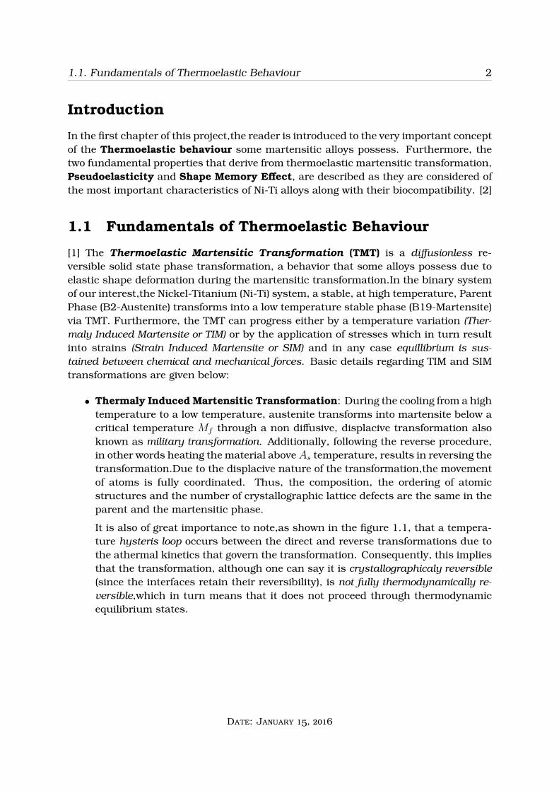
1.3 Pseudoelastic behaviour of NiTi speciment:a) The SIM transformation de-picted above Af and b) A qualitative stress-strain diagram with the stresshysteris loop. . . . . . . . . . . . . . . . . . . . . . . . . . . . . . . . . . . 5
1.4 Austenitic and twinned martensitic atomic structures . . . . . . . . . . . 61.5 Detwinned martensitic atomic structure . . . . . . . . . . . . . . . . . . . 61.6 Schematic depiction of OWSME . . . . . . . . . . . . . . . . . . . . . . . . 71.7 Schematic depiction of TWSME . . . . . . . . . . . . . . . . . . . . . . . . 8
2.1 Phase diagram of the NiTi alloy. . . . . . . . . . . . . . . . . . . . . . . . 142.2 Heating the deformed component. . . . . . . . . . . . . . . . . . . . . . . 162.3 Schematic depiction of a) Shape memory training and b) Stress-induced
martensitic transformation training. . . . . . . . . . . . . . . . . . . . . . 182.4 Schematic depiction of a) Thermal cycle training under constant load and
b) Over-deformation training . . . . . . . . . . . . . . . . . . . . . . . . . 19
3.1 A stent that has been used to open the coronary artery . . . . . . . . . . . 223.2 The Atral Septal occlusion device.Nitinol springs expand when released in
the desired spot [12] . . . . . . . . . . . . . . . . . . . . . . . . . . . . . . 233.3 Orthopedic implants . . . . . . . . . . . . . . . . . . . . . . . . . . . . . 243.4 Orthodontic and Ophthalmological applications . . . . . . . . . . . . . . . 253.5 a)Schematic depiction of SMA beams and b) SMA beams placed in the
chevrons of a jet engine. . . . . . . . . . . . . . . . . . . . . . . . . . . . . 263.6 SMA wires used in aircraft wings. . . . . . . . . . . . . . . . . . . . . . . 263.7 a) SMA wires are used to mimic muscle behaviour and b) Prosthetics
manipulating the SME . . . . . . . . . . . . . . . . . . . . . . . . . . . . . 273.8 Tube coupling process using SME. . . . . . . . . . . . . . . . . . . . . . . 27
ii
Acknowledgements
For the assignment of this very interesting and challenging project we would like toshow our gratidude to our professor, Dr. Gregory N. Hademenopoulos of University of
Thessaly, who fuelled us with the inspiration needed to accomplish such a difficulttask. We would also like to thank him for the opportunity he gave us to participate inhis advanced Physical Metallurgy course and for all the in-depth knowledge he has
entrusted us with, which will definitely be very useful in the near or distant future ofour carrer.
iii
Abstract
A lot of papers concerning several views on the NiTi alloys have been published. Thisproject has been carried out in order to present a unified overview of the Ni-Ti alloyand its unique Pseudoelastic and Shape Memory effects which are established throughproper fabrication and post-treatment of the alloy. More specifically, being one of themost versatile Shape Memory Alloys, Ni-Ti has a variety of applications in specific areassome of which are analyzed in this project as well.Among others, important Biomedicaland Industrial applications are described.
Keywords : Pseudoelasticity, Shape Memory Effect, Vaccum Melting and PowderMetallurgy Techniques for Ni-Ti, Thermo-mechanical Treatments, Training, BiomedicalApplications, Industrial Applications
iv

Chapter 1
Fundamental Properties of Ni-Ti
1
1.1. Fundamentals of Thermoelastic Behaviour 2
Introduction
In the first chapter of this project,the reader is introduced to the very important conceptof the Thermoelastic behaviour some martensitic alloys possess. Furthermore, thetwo fundamental properties that derive from thermoelastic martensitic transformation,Pseudoelasticity and Shape Memory Effect, are described as they are considered ofthe most important characteristics of Ni-Ti alloys along with their biocompatibility. [2]
1.1 Fundamentals of Thermoelastic Behaviour
[1] The Thermoelastic Martensitic Transformation (TMT) is a diffusionless re-versible solid state phase transformation, a behavior that some alloys possess due toelastic shape deformation during the martensitic transformation.In the binary systemof our interest,the Nickel-Titanium (Ni-Ti) system, a stable, at high temperature, ParentPhase (B2-Austenite) transforms into a low temperature stable phase (B19-Martensite)via TMT. Furthermore, the TMT can progress either by a temperature variation (Ther-maly Induced Martensite or TIM) or by the application of stresses which in turn resultinto strains (Strain Induced Martensite or SIM) and in any case equillibrium is sus-tained between chemical and mechanical forces. Basic details regarding TIM and SIMtransformations are given below:
• Thermaly Induced Martensitic Transformation: During the cooling from a hightemperature to a low temperature, austenite transforms into martensite below acritical temperature Mf through a non diffusive, displacive transformation alsoknown as military transformation. Additionally, following the reverse procedure,in other words heating the material aboveAs temperature, results in reversing thetransformation.Due to the displacive nature of the transformation,the movementof atoms is fully coordinated. Thus, the composition, the ordering of atomicstructures and the number of crystallographic lattice defects are the same in theparent and the martensitic phase.
It is also of great importance to note,as shown in the figure 1.1, that a tempera-ture hysteris loop occurs between the direct and reverse transformations due tothe athermal kinetics that govern the transformation. Consequently, this impliesthat the transformation, although one can say it is crystallographicaly reversible(since the interfaces retain their reversibility), is not fully thermodynamically re-versible,which in turn means that it does not proceed through thermodynamicequilibrium states.
Date: January 15, 2016

1.1. Fundamentals of Thermoelastic Behaviour 3
FIGURE 1.1: Thermal Hysterisis Loop Between Direct and Reverse Transformation
• Strain Induced Martensitic Transformation: The SIM transformation occurswhen external load is applied to the austenitic parent phase which brings aboutthe appearance of strains (due to stresses). After a critical strain-induced stressσMs is applied martensitic transformation begins and is completed for a stress just
bellow the yielding stress of the material σMf . During the unloading,the reverse
transformation occurs and, as illustrated in the figure 1.2,a stress hysterisisloop is produced resulting in two stress plateau. Additionaly, it can be easlyobserved that large strains can be recovered due to the reversible character ofthe transformation.
Date: January 15, 2016

1.2. Pseudoelasticity of Ni-Ti Alloys 4
FIGURE 1.2: Stress Hysterisis Loop Between Direct and Reverse Transformation.EA and EM correspond to the elastic modulus of Parent and Martensitic phases
respectively.
Finally it should also be noted that the interefaces between the parent and marten-sitic phases are coherent and this due to the fact that the phase transition displacementfield is continuous on the phase’s interface.
1.2 Pseudoelasticity of Ni-Ti Alloys
[2] The first of the two important properties that are to be discussed is Pseudoelasticity(PE). To begin with, in the NiTi alloys,the effect can be triggered while the material isloaded and unloaded isothermaly, at temperatures above the Af , thus the phenomenonis related to applying loads in the austenitic phase (in contrast with shape memoryeffect). More specifically, if external load is applied while the alloy is austenitic then theSIM transformation takes place transforming austenite to martensite via a reversibletransformation, while at the same time the alloy is able to achieve large strains up to10%. Even more ,due to the reversibility of the transformation ,after unloading thematerial is able to recover its original shape through an unloading plateau, which isdifferent than the loading and a stress hysterisis is introduced. Figure 1.3 presentsthe pseudoelastic effect analyzed above.
Date: January 15, 2016
1.3. Shape Memory Effect of Ni-Ti Alloys 5
FIGURE 1.3: Pseudoelastic behaviour of NiTi speciment:a) The SIM transformationdepicted above Af and b) A qualitative stress-strain diagram with the stress hysteris
loop.
At this point, it is cruicial to mention that the pseudoelastic phenomenon of theNiTi alloys strongly depends, either directly or indirectly, on specific factors suchas the composition of the alloy, manufacturing processes and the number of load-ing/unloading cycles. For instance, pseudoelasticity appears to be more extended fornear equatomic NiTi alloys. Widely used and with the desired thermoelastic proper-ties are alloys with Nickel content between 49 and 51 %. Furthermore, the system isvery sensitive to composition changes such that very small shifts of either of the com-ponenets lead to major changes in transformation temperatures, phases precipitatedand the reversibility of martensitic interfaces. Also, during the manufacturing processof the alloy, extra care is to be taken, since any impurities of other elements, suchas oxigen and carbon, seriously affect the pseudoelastic behaviour of the NiTi alloy.In addition, various tests have shown that, as the number of loading and unloadingcycles increases the pseudoelastic recovery of the alloy decreases and this is broughtabout because of the permenant slip of some interfaces which gradually leads to somestable martenstic phase. [1],[3]
1.3 Shape Memory Effect of Ni-Ti Alloys
The other distinct behavior of Shape Memory Alloys (SMAs) which is also attributedto the thermo-elastic martensitic transformation, is the Shape Memory Effect (SME). Inthis case, the reversible martensitic transformation is triggered not by induced strainsbut by changes in temperature. SMAs may have different kinds of shape memoryeffects. In particular,SME can be classified either as a One-Way Shape Memory Effect(OWSME) or a Two-Way Shape Memory Effect (TWSME) [3].
1.3.1 One-Way Shape Memory Effect
OWSME is the recovery of the original shape of an apparently plastically deformedmaterial simply upon heating to a certain temperature. A microscopic analysis is
Date: January 15, 2016
1.3. Shape Memory Effect of Ni-Ti Alloys 6
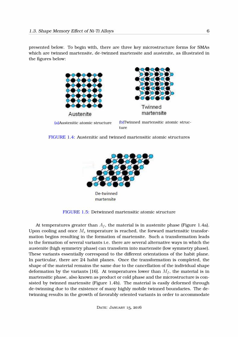
presented below. To begin with, there are three key microstructure forms for SMAswhich are twinned martensite, de-twinned martensite and austenite, as illustrated inthe figures below:
(a)Austenitic atomic structure (b)Twinned martensitic atomic struc-ture
FIGURE 1.4: Austenitic and twinned martensitic atomic structures
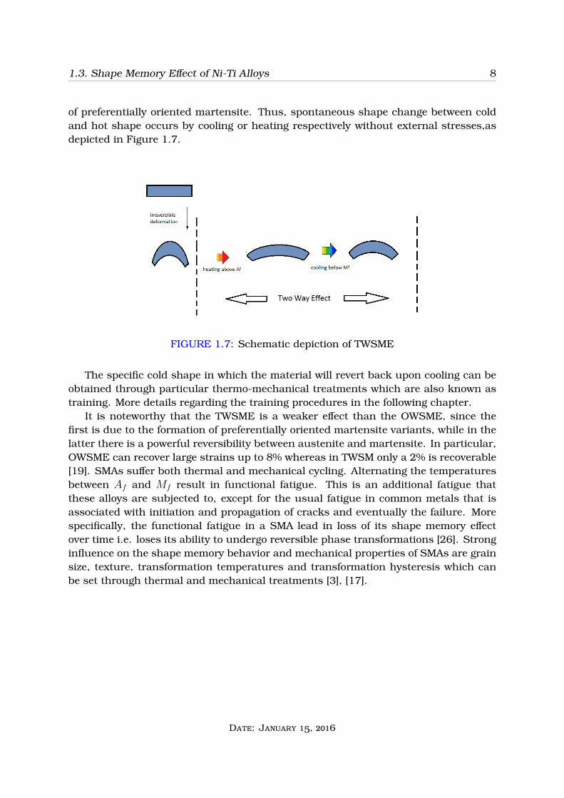
FIGURE 1.5: Detwinned martensitic atomic structure
At temperatures greater than Af , the material is in austenite phase (Figure 1.4a).Upon cooling and once Ms temperature is reached, the forward martensitic transfor-mation begins resulting in the formation of martensite. Such a transformation leadsto the formation of several variants i.e. there are several alternative ways in which theaustenite (high symmetry phase) can transform into martensite (low symmetry phase).These variants essentially correspond to the different orientations of the habit plane.In particular, there are 24 habit planes. Once the transformation is completed, theshape of the material remains the same due to the cancellation of the individual shapedeformation by the variants [16]. At temperatures lower than Mf , the material is inmartensitic phase, also known as product or cold phase and the microstructure is con-sisted by twinned martensite (Figure 1.4b). The material is easily deformed throughde-twinning due to the existence of many highly mobile twinned boundaries. The de-twinning results in the growth of favorably oriented variants in order to accommodate
Date: January 15, 2016

1.3. Shape Memory Effect of Ni-Ti Alloys 7
the strain, which most of the times leads in single variant (Figure 1.5). The de-twinnedmartensite will be maintained in the microstructure even if the stress is completely re-moved. Upon heating, the reverse phase transformation takes place which starts at As
and finishes at Af temperatures, respectively. Although, there are many ways in whichthe austenite can be transformed to martensite, there is only one manner in which theaustenite is formed. Eventually, the original shape is recovered and upon cooling theabove mechanism can be repeated. The above description is briefly illustrated in Figure1.6.
(a)
(b)
FIGURE 1.6: Schematic depiction of OWSME
1.3.2 Two-Way Shape Memory Effect
The other type of the SME is the TWSME. As stated above,in the OWSME only the shapeof the parent phase can be recovered. A SMA with the TWSME property has the abilityto remember both its parent and product phases and spontaneously change shapesupon heating and cooling. It is worth noting that the TWSME is not an inherentproperty in SMAs but instead is a learned behavior. This can be accomplished bycomplicated thermo-mechanical procedures known as ”training” [19]. The training,involves repeated deformation and transformations between a favorable configurationof martensite and austenite. The substantial difference between the OWSME andthe TWSME is that the shape change in the latter is generated even without externalstresses [3].
At temperatures below Mf the material is in martensite phase. In contrast withthe OWSME,an irreversible amount of deformation is introduced i.e. the martensite isdeformed beyond its yield strength where slip occurs and dislocations are introduced.Upon heating there is no 100% shape recovery due to the retardation of the marten-sitic transformation by the dislocations. Afterwards,upon cooling below Mf ,a specificconfiguration of martensite is formed resulting in a specific cold shape. This specificconfiguration of martensite is attributed to the anisotropic field that is introduceddue to dislocations which are maintained in the parent phase and favor the formation
Date: January 15, 2016
1.3. Shape Memory Effect of Ni-Ti Alloys 8
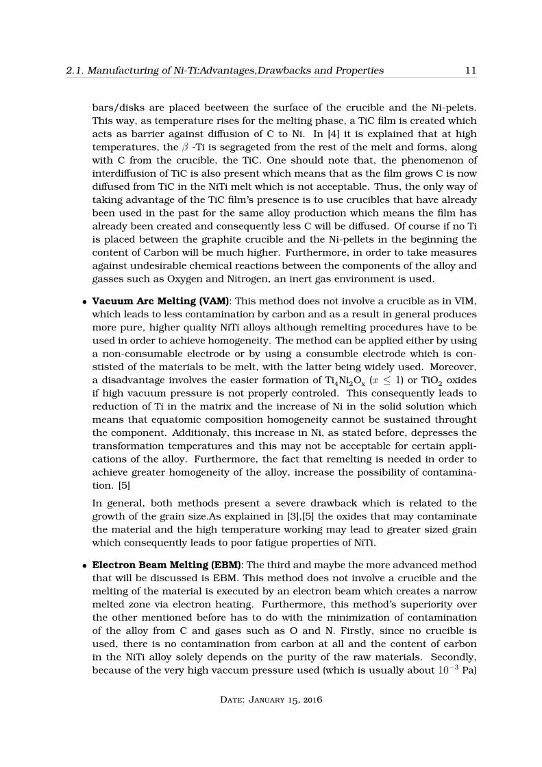
of preferentially oriented martensite. Thus, spontaneous shape change between coldand hot shape occurs by cooling or heating respectively without external stresses,asdepicted in Figure 1.7.
FIGURE 1.7: Schematic depiction of TWSME
The specific cold shape in which the material will revert back upon cooling can beobtained through particular thermo-mechanical treatments which are also known astraining. More details regarding the training procedures in the following chapter.
It is noteworthy that the TWSME is a weaker effect than the OWSME, since thefirst is due to the formation of preferentially oriented martensite variants, while in thelatter there is a powerful reversibility between austenite and martensite. In particular,OWSME can recover large strains up to 8% whereas in TWSM only a 2% is recoverable[19]. SMAs suffer both thermal and mechanical cycling. Alternating the temperaturesbetween Af and Mf result in functional fatigue. This is an additional fatigue thatthese alloys are subjected to, except for the usual fatigue in common metals that isassociated with initiation and propagation of cracks and eventually the failure. Morespecifically, the functional fatigue in a SMA lead in loss of its shape memory effectover time i.e. loses its ability to undergo reversible phase transformations [26]. Stronginfluence on the shape memory behavior and mechanical properties of SMAs are grainsize, texture, transformation temperatures and transformation hysteresis which canbe set through thermal and mechanical treatments [3], [17].
Date: January 15, 2016

Chapter 2
Manufacturing and Post-Processes:Training the Ni-Ti Alloy
9

2.1. Manufacturing of Ni-Ti:Advantages,Drawbacks and Properties 10
Introduction
In the second chapter,manufacturing processes and post-heat treatments, which areactually two sides of the same coin, are discussed. The first part is devoted to theconnection between the selection and execution of the process used to produce theNitinol alloy and the Shape Memory Effects(SME) that are achieved. The two mostcommonly used methods of production are Casting and Powder Metallurgy with eachone of them including a variety of specific processes. In the second part, Thermo-mechanical treatments and the so called ”Training” and the way they affect thefundamental properties are analyzed. [3],[4]
2.1 Manufacturing of Ni-Ti:Advantages,Drawbacks andProperties
Forming and preparation for the production of Nitinol components with the desiredSME is of great importance. As far as fabrication of NiTi alloys is concerned, thetwo methods systematicaly used involve specific casting methods or powder metallurgymethods followed by other mechanical processes such as Hot or Cold Working, SurfaceTreatments and Heat-Treatments ,with the latter having an important role in the shapesetting of the Nitinol. Furthermore, the manufacturing process of the specific SMA iscritical and specifically affects composition homogeneity, ductility, machinability, biocm-patibility as well as microstructure and the transformation temperatures all of which areimportant for the applications of the material.
2.1.1 Cast-Produced Ni-Ti
The first method to be discussed involves producing the NiTi component via a castingprocess. The raw materials must be of as high purity as possible, since the existenceof impurites and non-metallic elements can seriously affect the unity and homogeneityof the alloy, thus create uneven composition distribution and change vital properties ofthe material. More specifically, the techniques that are used include Vacuum InductionMelting (VIM), Vacuum Arc Melting (VAM) and Electron Beam Melting (EBM). The basicresults, in terms of material and properties,are analyzed bellow.
• Vacuum Induction Melting (VIM): This method involves the use of a graphitecrucible, where pure raw Ni-pellets and Ti bars(or disks) melt in order to createthe Ni-Ti system. First of all it should be noted that graphite is used as thecrucible material as other materials have various problems(such as a tedencyfor thermal cracking due to high temperatures) and high costs. Additionaly, interms of achieving homogeneity of the composition throught the material, thearrangement of the materials in the crucible is important. In order to increasethe level of purity of the material, the contamination of the liquid alloy by carbonparticles needs to minimized. More specifically in order to achieve this Titanium
Date: January 15, 2016
2.1. Manufacturing of Ni-Ti:Advantages,Drawbacks and Properties 11
bars/disks are placed beetween the surface of the crucible and the Ni-pelets.This way, as temperature rises for the melting phase, a TiC film is created whichacts as barrier against diffusion of C to Ni. In [4] it is explained that at hightemperatures, the β -Ti is segrageted from the rest of the melt and forms, alongwith C from the crucible, the TiC. One should note that, the phenomenon ofinterdiffusion of TiC is also present which means that as the film grows C is nowdiffused from TiC in the NiTi melt which is not acceptable. Thus, the only way oftaking advantage of the TiC film’s presence is to use crucibles that have alreadybeen used in the past for the same alloy production which means the film hasalready been created and consequently less C will be diffused. Of course if no Tiis placed between the graphite crucible and the Ni-pellets in the beginning thecontent of Carbon will be much higher. Furthermore, in order to take measuresagainst undesirable chemical reactions between the components of the alloy andgasses such as Oxygen and Nitrogen, an inert gas environment is used.
• Vacuum Arc Melting (VAM): This method does not involve a crucible as in VIM,which leads to less contamination by carbon and as a result in general producesmore pure, higher quality NiTi alloys although remelting procedures have to beused in order to achieve homogeneity. The method can be applied either by usinga non-consumable electrode or by using a consumble electrode which is con-stisted of the materials to be melt, with the latter being widely used. Moreover,a disadvantage involves the easier formation of Ti4Ni2Ox (x ≤ 1) or TiO2 oxidesif high vacuum pressure is not properly controled. This consequently leads toreduction of Ti in the matrix and the increase of Ni in the solid solution whichmeans that equatomic composition homogeneity cannot be sustained throughtthe component. Additionaly, this increase in Ni, as stated before, depresses thetransformation temperatures and this may not be acceptable for certain appli-cations of the alloy. Furthermore, the fact that remelting is needed in order toachieve greater homogeneity of the alloy, increase the possibility of contamina-tion. [5]
In general, both methods present a severe drawback which is related to thegrowth of the grain size.As explained in [3],[5] the oxides that may contaminatethe material and the high temperature working may lead to greater sized grainwhich consequently leads to poor fatigue properties of NiTi.
• Electron Beam Melting (EBM): The third and maybe the more advanced methodthat will be discussed is EBM. This method does not involve a crucible and themelting of the material is executed by an electron beam which creates a narrowmelted zone via electron heating. Furthermore, this method’s superiority overthe other mentioned before has to do with the minimization of contaminationof the alloy from C and gases such as O and N. Firstly, since no crucible isused, there is no contamination from carbon at all and the content of carbonin the NiTi alloy solely depends on the purity of the raw materials. Secondly,because of the very high vaccum pressure used (which is usually about 10−3 Pa)
Date: January 15, 2016

2.1. Manufacturing of Ni-Ti:Advantages,Drawbacks and Properties 12
oxygen contamination is also minimized consequently leading to the productionof more pure NiTi alloys with even better fatigue properties. Nevertheless,despitethe method’s capability of producing high quality alloys with very small amountof impurities, two serious drawbacks should be mentioned. The first has to dowith fact that due to high vaccum pressure during the melting, it is difficult tocontrol nominal chemical composition because of some component evaporationand as a result a change in martensitic transformation temperatures occurs. Thesecond disadvantage of this method is that small to medium sized materials areproduced which makes it difficult to be used for large quantity production. [3],[6]
2.1.2 Ni-Ti Produced via Powder Metallurgical Methods
The second method that is used to fabricate the NiTi alloys involves several powdermetallurgical methods. In this case a variety of different techniques can be used inorder to produce the NiTi alloy using powders of Ni and Ti elements as the starting ma-terial which are produced using rapid solidifiaction processes such as Gas Atomization.The powder used may also be prealloyed which improves the composition homogeneityof the final product.
The basic steps to be followed in most methods include; a) Powder Blending, b)Mold Compaction and c) Sintering in a furnace. To begin with, the first step invlovesblending the desired powders in order for a uniform distribution of each componet’singredient to be achieved (this step is used for elementary powders since in prealloyedones the proper proportion is already present in each of the particles). Furthemore,after getting the desired distribution, the parts are consolidated via high pressingmethods in molds and dies which consequently create very densified, but neverthelessstill not completely compact, componets said to be in a green state. At this pointthe components are only prepared for handling purposes and any additional loadsapplied can take the component apart. The third step, intended to be used in order toachieve the density required for the actual component to be usable, includes heatingthe material in a sintering furnace at a temperature high enough (but bellow meltingpoint of the materials) so diffusion of each of the ingridients from one particle to theother can take place. More specifically, with the increase in temperature, atomicdiffusion leads to the formation of necks between the particles which grow larger astime passes and bring about the desired density increase. It is important to notethat the driving force for densification is the decrease of Gibbs free energy due to thedecrease in surface energy because of the formation of the neck, that has a shapewhich has less surface energy than the almost spherical spheres used in the firstplace. Additionaly, the more dense and with more uniform pores the material is beforesintering, the faster is the porous destruction since in this case particle boundaries arecloser to each other so the diffusion distance is shorter. Finally, it is also importantto mention that if elementary powders are used, since sintering takes place at highconstant temperatures, Kirkendall’s porosity may occur in the component due to thediffusivity of Ti in Ni being greater than the opposite. [27], [28], [29]
Date: January 15, 2016
2.1. Manufacturing of Ni-Ti:Advantages,Drawbacks and Properties 13
In general, the fundamental benefits that derive from this method include verygood composition homogeneity throught the material compared to those acquired viavacuum melting techniques and the production of NiTi alloys with great porosity, aproperty that is critical for the biocompatibility of NiTi in biomedical applications.
In terms of specific techniques that can be used to produce NiTi alloys, they canbe divided into two major categories based on [3] and [7];Conventional processes andRapid Manufacturing processes.
• Conventional processes: These processes basically include 6 methods in or-der to produce NiTi components from elementary or prealloyed powders. Theseare; Self ropagating High temperature Synthesis (SHS),Conventional Sintering(CS),Metal or Powder Injection Molding (MIM),Space Holder Technique (SHT) [7],Hot Isostatic Pressing (HIP), Spark Plasma Sintering (SPS). In all methods de-scribed above,except for SHT, the precipitation of the intermetallics Ti2Ni, TiNi3,Ti3Ni4 in more or less quantities, cannot be avoided. Unfortunately, the aformen-tioned phases are stable, do not possess pseudoelastic or shape memory effectsand are very difficult to remove. Nevertheless, as far as biocompatibility is con-cerned, most of the methods can provide sufficient amount of porosity(between40 and 60 %) along with acceptable mechanical properties.
• Rapid (or Additive) Manufacturing processes: This, state of the art, categoryof methods is used in a variety of disciplines and fields and it allows the abuseof stereolithography principles combined with the 3D computer aided design (3DCAD) in order to produce the desired-shaped material that may be of complexgeometry and cannot be produced by conventional means. The common meth-ods used to produce NiTi components via Additive metallurgy include; SelectiveLaser Sintering (SLS), Selective Laser Melting (SLM), Laser Engineered Net Shap-ing (LENS) and Electron Beam Melting (EBM). Furthermore, rapid manufacturingprocesses pose as one of the methods for producing porous NiTi with great con-trol over porosity’s volumetric fraction and with acceptable mechanical propertiessuch as corrosion and fatigue resistance that can be improved by properly con-troling the operating conditions and particle size.
Nevertheless ,it should also be mentioned that, a serious drawback of powder met-allurgical methods compared to vacuum melting methods is the greatest vulnerabilityof the alloy to impurities such as Oxygen. According to [4] the content of oxygen mayusually vary between 1500 and 3000 ppm, which is about 3 to 6 times more than thatof the vacuum melting processes (worst case 500 ppm). This contamination can causeserious depletion of Ti from the matrix, forming oxides and consequently increase thegrain size of the material [5]. As a result, NiTi alloys fabricated this way tend to bemore brittle which is generally unwanted. Additionaly, transformation temperaturesare also affected by the precipitation of oxides and intermetallic phases.
Date: January 15, 2016
2.2. Thermo-mechanical Treatments of Ni-Ti Alloys 14
2.2 Thermo-mechanical Treatments of Ni-Ti Alloys
Thermal and mechanical treatments of fabricated NiTi’s are very important in order toobtain desired properties suitable to a specific application. It is essential to have acombination of optimum mechanical properties and SME or pseudoelastic behaviorand for that the material is cold worked and heat treated. The amount of cold workingand heat treatment conditions lead to different microstructures and consequently, indifferent properties [3]. Thus,the phase diagram of NiTi and the influence of precipitatedphases of the alloy have to be be considered.
2.2.1 Phase Diagram of Binary Ni-Ti Alloy
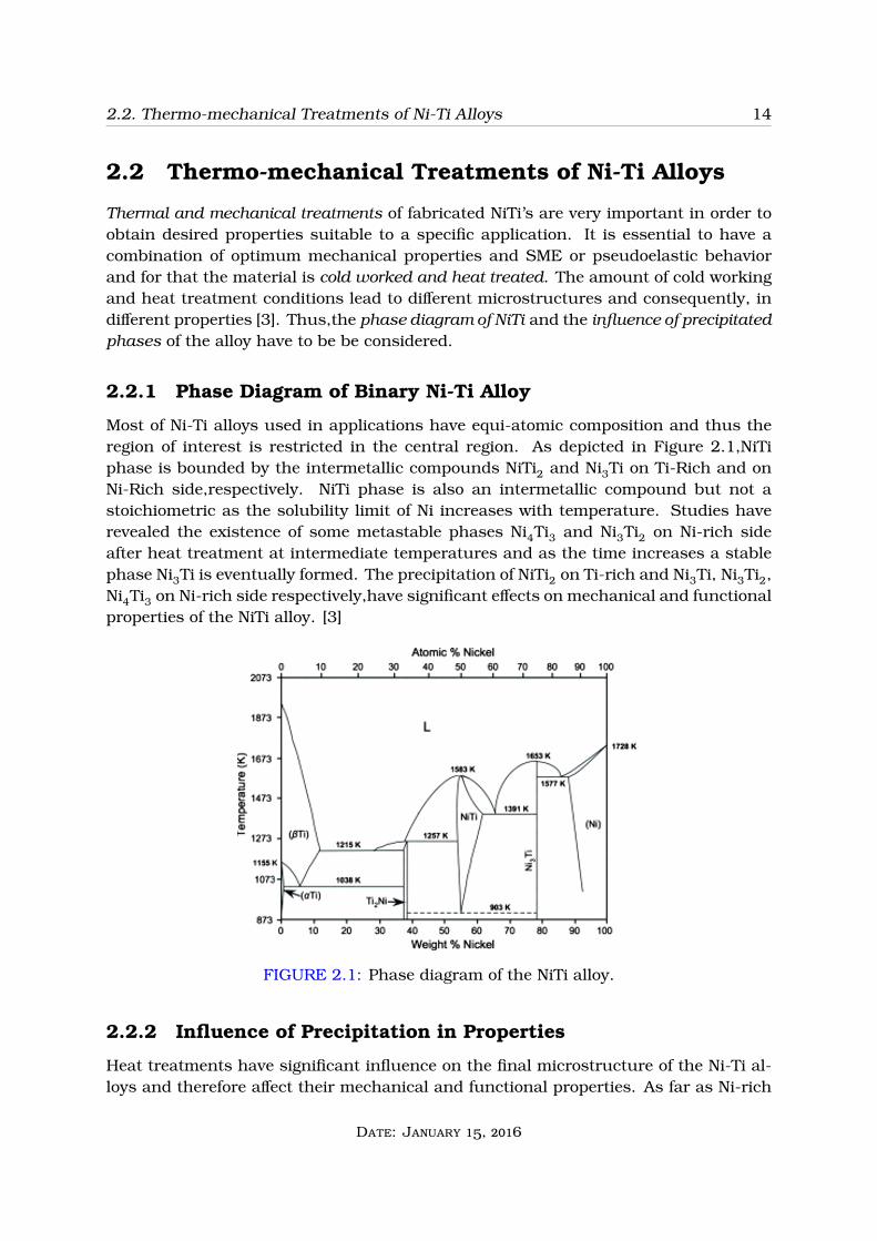
Most of Ni-Ti alloys used in applications have equi-atomic composition and thus theregion of interest is restricted in the central region. As depicted in Figure 2.1,NiTiphase is bounded by the intermetallic compounds NiTi2 and Ni3Ti on Ti-Rich and onNi-Rich side,respectively. NiTi phase is also an intermetallic compound but not astoichiometric as the solubility limit of Ni increases with temperature. Studies haverevealed the existence of some metastable phases Ni4Ti3 and Ni3Ti2 on Ni-rich sideafter heat treatment at intermediate temperatures and as the time increases a stablephase Ni3Ti is eventually formed. The precipitation of NiTi2 on Ti-rich and Ni3Ti, Ni3Ti2,Ni4Ti3 on Ni-rich side respectively,have significant effects on mechanical and functionalproperties of the NiTi alloy. [3]
FIGURE 2.1: Phase diagram of the NiTi alloy.
2.2.2 Influence of Precipitation in Properties
Heat treatments have significant influence on the final microstructure of the Ni-Ti al-loys and therefore affect their mechanical and functional properties. As far as Ni-rich
Date: January 15, 2016
2.2. Thermo-mechanical Treatments of Ni-Ti Alloys 15
alloys are concerned, there may exist various precipitation sequences depending onthe heat treatment conditions and on the alloy’s composition. In particular, high ag-ing temperatures and time lead in the formation of Ni3Ti precipitates, intermediateaging conditions lead in Ni3Ti2 precipitates and low aging conditions lead in Ni4Ti3precipitates. Regarding the latter, in the early stages of aging, it possesses coherencywith the matrix [17]. Most of the biomedical applications use Ni-rich alloys since thetransformation temperatures are strongly dependent on Ni content. Precipitation ofNi-rich particles in Ni-rich alloys leads in a decrease of Ni at the matrix since Ni atomsparticipate in the formation of these precipitates resulting eventually in an increase oftransformation temperatures [3]. The size and the dispersion of the precipitates havesignificant effects on mechanical properties, shape memory effect and pseudoelasticbehavior. These two parameters depend on the heat treatment conditions such astemperature and time. As the aging time increases coarser dispersion, larger precip-itates and coherency loss are observed. Fine dispersion and small sizes strengthenthe alloy since dislocation’s motion is more effectively blocked than with coarser dis-persion and larger particles. Moreover, coherent precipitates introduce a stress fieldwhich strengthens the alloy and affects the mobility of the martensitic interfaces [3].The precipitation of the new phase takes place by nucleation and growth. The totalkinetic of the precipitation follows the C-kinetics in which the nucleation and diffusionrates are optimum at intermediate temperatures. The precipitation may take placeeither homogeneously or heterogeneously depending on the supersaturation. High su-persaturation brings about homogeneous nucleation which is not assisted by latticedefects and the precipitates are dispersed at the grain interior [18]. Whenever the driv-ing force is not high enough to enable homogeneous nucleation, lattice defects suchas grain boundaries contribute the precipitation. Regarding the morphology of thenew phase, both the interfacial and strain energy are considered and the shape of theparticles is that one which minimizes the sum of these energies [16].
Whether the Ni-Ti alloy is used for its SME or its pseudoelastic behavior, its me-chanical properties combined with these unique properties must be optimized to meetthe application demands. The final steps in the manufacturing process of a Ni-Ti alloyare cold working and heat treatment. Cold working is accomplished for dimensionalcontrol. The introduced dislocations by cold working strengthen the alloy but reduceductility and impede martensite interfaces. Thus, heat treatment must be followed torearrange these dislocations, increase ductility and restore the SME [3]. For pseudoe-lasticity, the dislocations should not be eliminated so the parent phase maintains highyield strength. Heat treatment leads in phase transformations where precipitates areformed which contribute in the alloy’s strengthening. Attention should be paid duringthe heat treatment since high aging conditions lead in growth and eventually in dis-solution of the precipitates leading in a weaker parent phase. Grain size and textureare also important parameters and can be adjusted properly for optimum performance[17].
Date: January 15, 2016

2.3. The ”Training” Procedure of Ni-Ti Alloys 16
2.3 The ”Training” Procedure of Ni-Ti Alloys
In this section details regarding the procedure known as ”training” are presented whichcan be applied generally for any SMA not only the NiTi alloy. More specifically theclassical One Way Shape Setting is analyzed which is the basic process for giving thedisired ”parent” phase shape. Furthermore the non-inherent TWSME is also described.
2.3.1 Shape Setting of a SMA
Whether the SMA is used for its superelastic property or its SME a preferred shapesuitable to the application must be obtained. This is done by a process known asShape Setting. In particular, Shape Setting refers to a procedure used to form thedesired shape that follows cold working. This is done in the following way: The sampleis formed to the desired shape and is hold in that position tightly. Afterwards, thecomponet is heat treated to a certain temperature that is enough to obtain a uniformtemperature on its entire mass. The heat treatment time depends on sample’s size. Itis quite essential that the sample remains still while being heat treated otherwise therequired shape will not be set. [20]
FIGURE 2.2: Heating the deformed component.
Once at room temperature the alloy has transformed into the martensitic state andtwinning has occurred to maintain the macroscopic shape,as discussed in chapter 1.
2.3.2 Training Procedure for the TWSME
As noted in the previous chapter, a SMA with the TWSME has the ability to rememberand eventually recover both its hot (austenite) and cold (martensite) phase shapessimply upon heating and cooling, respectively [3]. The TWSME is not an innate propertyof SMAs thus, particular thermo-mechanical treatments also known as training, mustbe followed before such a property is obtained. The training can be done with avariety of different ways and all are focused in optimizing the TWSME behavior. Mostof the training procedures involve repetitive phase transformations between austeniteand a preferred configuration of martensite. Furthermore, certain martensite variants
Date: January 15, 2016
2.3. The ”Training” Procedure of Ni-Ti Alloys 17
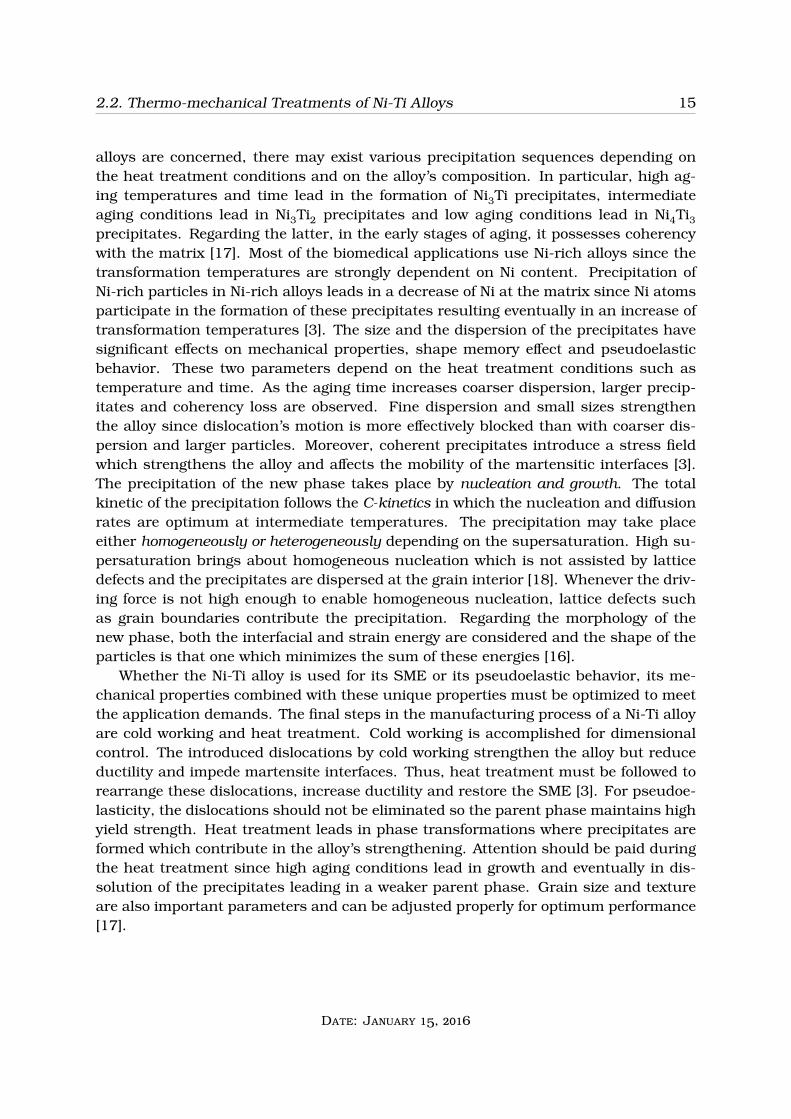
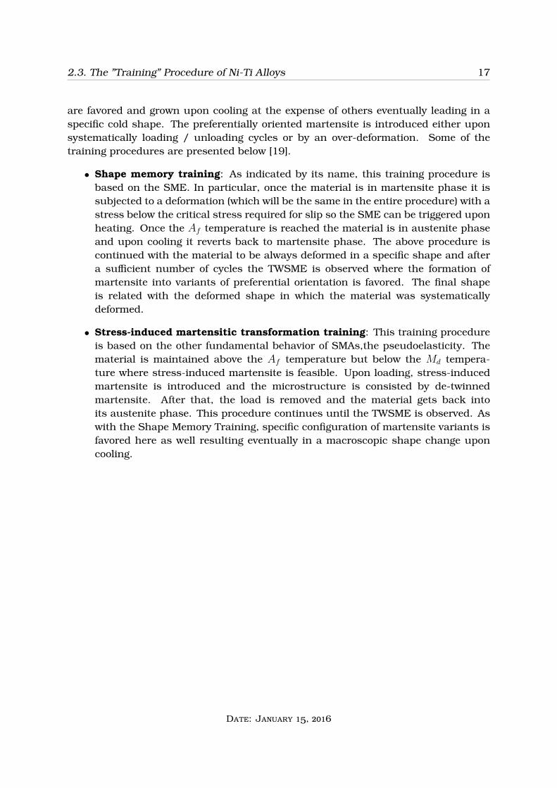
are favored and grown upon cooling at the expense of others eventually leading in aspecific cold shape. The preferentially oriented martensite is introduced either uponsystematically loading / unloading cycles or by an over-deformation. Some of thetraining procedures are presented below [19].
• Shape memory training: As indicated by its name, this training procedure isbased on the SME. In particular, once the material is in martensite phase it issubjected to a deformation (which will be the same in the entire procedure) with astress below the critical stress required for slip so the SME can be triggered uponheating. Once the Af temperature is reached the material is in austenite phaseand upon cooling it reverts back to martensite phase. The above procedure iscontinued with the material to be always deformed in a specific shape and aftera sufficient number of cycles the TWSME is observed where the formation ofmartensite into variants of preferential orientation is favored. The final shapeis related with the deformed shape in which the material was systematicallydeformed.
• Stress-induced martensitic transformation training: This training procedureis based on the other fundamental behavior of SMAs,the pseudoelasticity. Thematerial is maintained above the Af temperature but below the Md tempera-ture where stress-induced martensite is feasible. Upon loading, stress-inducedmartensite is introduced and the microstructure is consisted by de-twinnedmartensite. After that, the load is removed and the material gets back intoits austenite phase. This procedure continues until the TWSME is observed. Aswith the Shape Memory Training, specific configuration of martensite variants isfavored here as well resulting eventually in a macroscopic shape change uponcooling.
Date: January 15, 2016
2.3. The ”Training” Procedure of Ni-Ti Alloys 18
(a)
(b)
FIGURE 2.3: Schematic depiction of a) Shape memory training and b) Stress-inducedmartensitic transformation training.
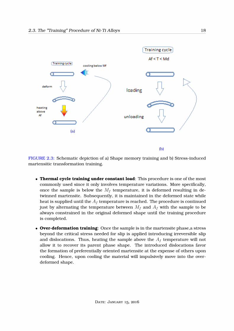
• Thermal cycle training under constant load: This procedure is one of the mostcommonly used since it only involves temperature variations. More specifically,once the sample is below the Mf temperature, it is deformed resulting in de-twinned martensite. Subsequently, it is maintained in the deformed state whileheat is supplied until the Af temperature is reached. The procedure is continuedjust by alternating the temperature between Mf and Af with the sample to bealways constrained in the original deformed shape until the training procedureis completed.
• Over-deformation training: Once the sample is in the martensite phase,a stressbeyond the critical stress needed for slip is applied introducing irreversible slipand dislocations. Thus, heating the sample above the Af temperature will notallow it to recover its parent phase shape. The introduced dislocations favorthe formation of preferentially oriented martensite at the expense of others uponcooling. Hence, upon cooling the material will impulsively move into the over-deformed shape.
Date: January 15, 2016

2.3. The ”Training” Procedure of Ni-Ti Alloys 19
(a)
(b)
FIGURE 2.4: Schematic depiction of a) Thermal cycle training under constant load andb) Over-deformation training
Date: January 15, 2016

Chapter 3
Important Applications of Ni-Ti Alloys
20

3.1. Biomedical Applications 21
Introduction
The third chapter of this project is dedicated to the presentation of important applica-tions of the Nitinol products. More specifically, it has been made clear throught thelength of this project that the special properties of pseudoelastic behaviour and shapememory effect that Nitinol products possess have allowed these alloys to be used insituations where conventional metals and alloys do not meet the standards. NiTi alloysare used in the Biomedical Discipline with exceptional results especially in Ortho-pedics and Cardiovascular applications and in a smaller extend in Orthodondics,Neurosurgery, Ophthalmology, Urology and more. Furthermore, some Industrialapplications are also presented. [8],[9],[10],[11]
3.1 Biomedical Applications
For many decades there has been a struggle, with the cooperation between both med-ical and engineering scientific communities, to find materials that could possibly beused for the prevention or treatment of certain medical diseases and human bodymalfunction. Especially, when it comes to interaction between human body and mate-rials,for example in the form of implants, most materials have proved to be insufficientand sometimes hazardous for the patient’s health. Fortunately, the development ofmaterials with high biocompatibility and special properties has changed all that. TheNitinol product,which is a near equatomic alloy of Nickel-Titanium is such an example.The pseudoelastic effect along with the matching of its Young’s Modulus with the oneof the human bone make it a great implant material in orthopedics. Additionally, theshape memory effect of the material which allows it to regain a specific shape when cer-tain conditions are met render the material usable for minimum invasive applicationsin cardiovascular diseases and medical tests which otherwise would be very difficult toimplement.
3.1.1 Cardiovascular Applications
The three fundamental applications of Nitinol products for cardiovascular disease treat-ments and prevention are applications in Angiorgraphy, Angioplasty and Atrial septalDefect with each one analized bellow.
• Angiorgraphy: Angiography or Arteriography is a medical imaging techniqueused to visualize the inside of blood vessels and organs of the body, with partic-ular interest in the arteries, veins, and the heart chambers. The method involvesintroducing a radiopaque contrast medium through a catheter to the heart cham-ber or the coronary artery. X-ray imaging is then used in order to get an idea ofthe blood flow and the vessels inside the cardiovascular system and find out ifany obstructions to the normal blood flow exist. In order for the catheter to reachthe desired location in the body,it has to be guided by a guideline wire which
Date: January 15, 2016
3.1. Biomedical Applications 22
is first inserted and carefully propagated to the spot. While the guideline wiremoves along the paths of the artery or vains,because of the many and continuousdiversions that exist due to the complexity of the system,strains are produced inthe material.In conventional metals,such as stainless steel with ability to have aonly a small range of elastic strains,permenant strains may be introduced andthus lead to a permenant twist(bending) of the wire a phenomenon known as”kinking”. This permenant curvature of the wire makes it difficult to maneuverwhich may consequently lead to the damaging of the artery,if propagation is con-tiniued or while it follows the exiting direction. On the contrary,the pseudoelasticeffect of the Nitinol allows it to move through the artery safely and easly,avoidingpermenant bendings due to its ability to develop large non-linear elastic strains.[10]
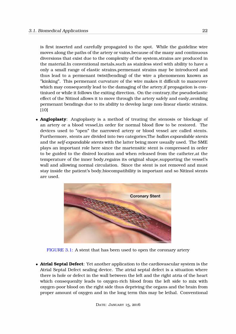
• Angioplasty: Angioplasty is a method of treating the stenosis or blockage ofan artery or a blood vessel,in order for normal blood flow to be restored. Thedevices used to ”open” the narrowed artery or blood vessel are called stents.Furthermore, stents are divided into two categories;The ballon expandable stentsand the self-expandable stents with the latter being more usually used. The SMEplays an important role here since the martensitic stent is compressed in orderto be guided to the disired location and when released from the catheter,at thetemperature of the inner body,regains its original shape,supporting the vessel’swall and allowing normal circulation. Since the stent is not removed and muststay inside the patient’s body,biocompatibility is important and so Nitinol stentsare used.
FIGURE 3.1: A stent that has been used to open the coronary artery
• Atrial Septal Defect: Yet another application to the cardiovascular system is theAtrial Septal Defect sealing device. The atrial septal defect is a situation wherethere is hole or defect in the wall between the left and the right atria of the heartwhich consequenlty leads to oxygen-rich blood from the left side to mix withoxygen-poor blood on the right side thus depriving the organs and the brain fromproper amount of oxygen and in the long term this may be lethal. Conventional
Date: January 15, 2016

3.1. Biomedical Applications 23
surgery techniques which aim at sewing the hole used extensively in the pastinvolve a very high risk for the patient’s life. Luckily,with the development ofminimum invasive methods,sealing devices can be guided to the spot instead. Aswith angioplasty,the SME of Nitinol is abused in the situation as a two componentNitinol framework is guided on the right and the left side of the hole througha catheter and when released the parts regain their original shape sealing thehole.[9]
FIGURE 3.2: The Atral Septal occlusion device.Nitinol springs expand when releasedin the desired spot [12]
3.1.2 Orthopedic Applications
Another major field of medical treatment Nitinol products have broad applications isorthopedic treatments. As stated before porous NiTi products are most of the timespreferred,due to the fact that when used as an implant in contact with the bone’s tissuegrowth and fluid flow should be allowed,in order for the organism not to reject it. Never-theless,extra care needs to be taken at the engineering of the alloy with proper surfacetreatments so to minimize the possible release of Nickel into the patient’s body,sinceNickel can cause allergic reactions,nostril and lung cancer,pneumonia,rhinitis andchronic sinusitis. Some fundamental applications of Nitinol in orthopedics are de-scribed bellow.
• Spinal Vertebral Spacer and Spinal Rod: Both devices are used as implants inorder to help with the correction of scoliosis. The first one is placed between twovertebrae providing local support to the spine preventing abnormal movements.The Pseudoelastic effect of Nitinol provides constant stabalizing force to the spineregardless of the patient’s position since it can provide large non-permenantstrains. The second can potentially be used in humans in the future to graduallyreturn the shape of the spine to a corrected position making advantage of theSME and biocompatibility of Nitinol.
Date: January 15, 2016

3.1. Biomedical Applications 24
• Medical staples for bone fractures: Another application of the Nitinol usesthe SME of the alloy to recover the fracture between two bones.The staples aremechanically deformed from the closed to the open state before being used. Thestaples are then placed to the region of the fracture and via an external heatingsource they are heated in order to regain their closed form and compress thebones together.
• Knee and Hip implants: Possible use of Niti implants in total knee or hip jointreplacement is discussed in the biomedical community,due to the combination ofunique properties with acceptable conventional properties.As stated in [8] ascep-tic loosening which occurs due wear of the implant material,problematic loadingtranfer system and low compatibility between implant-bone is a major concernduring this treatment so materials such as Nitinol that can combine both goodmechanical and pseudoelastic properties along with biocompatibility may be usedin such situations.
(a)Spinal vertebral spacers (b)Model depicting a knee implant from Nitinol[13]
FIGURE 3.3: Orthopedic implants
3.1.3 Aplications in other biomedical areas
In this section,other promising uses of the Nitinol materials are reviewed briefely aseach one of them involves a lot of information one can find more details in [10] and [11]
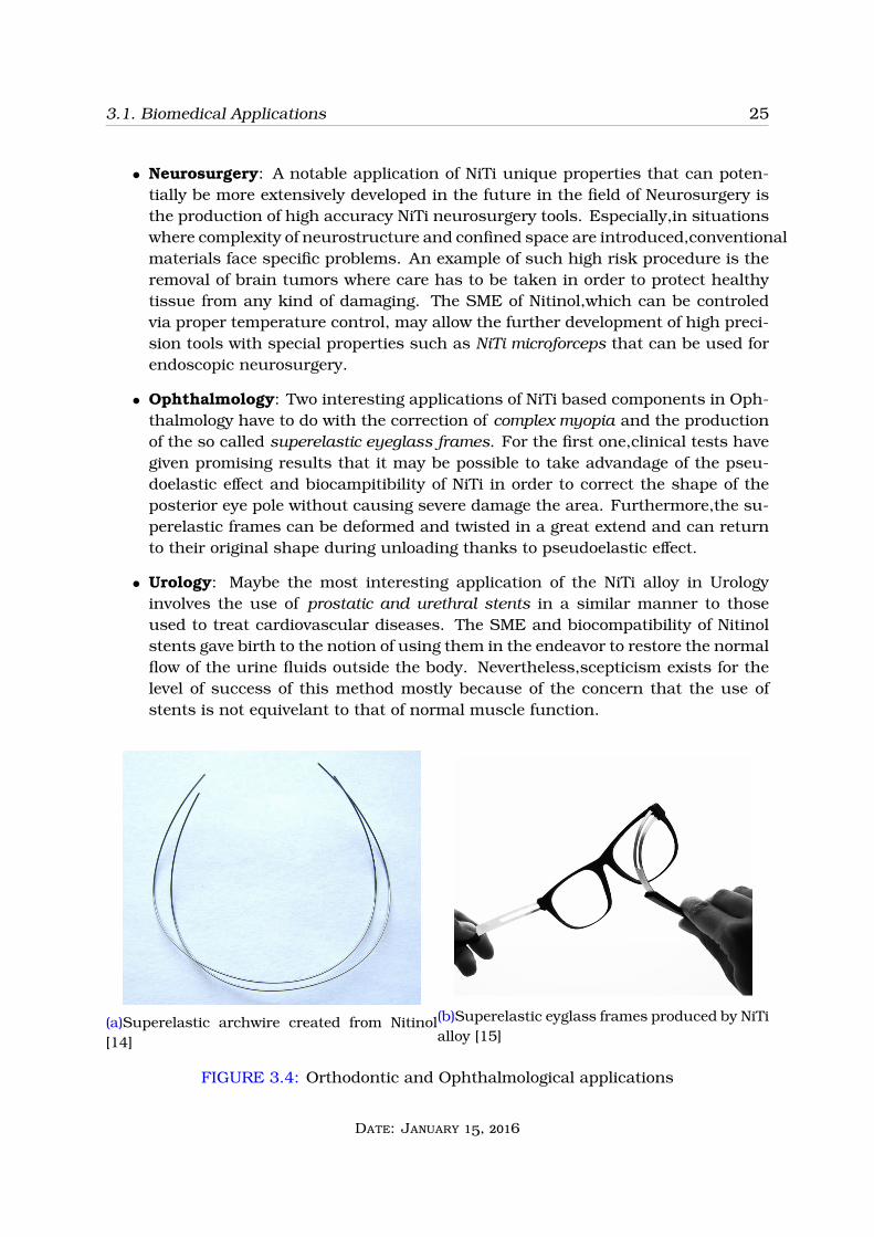
• Orthodontics: In orthodontics, NiTi alloys are used for the production of paleteexpanders and archwires which are used in treatments in order to,gradually overtime,move the patient’s teeth to the correct position.The method takes advantageof the pseudoelastic effect of the alloy which allows it to take large deformationswith almost constant loadings and as a result minimize the discomfort of thepatient and eliminate damaging of bone tissue. Transformation temperatures ofthe materials in this case should be close to that of the oral cavity so specificmanufacturing methods should be applied accordingly. Additionaly, NiTi alloysare used to create the tips of dental drills in order to allow the tool to have a goodrotation ability even after bending inside a tooth cavity.
Date: January 15, 2016
3.1. Biomedical Applications 25
• Neurosurgery: A notable application of NiTi unique properties that can poten-tially be more extensively developed in the future in the field of Neurosurgery isthe production of high accuracy NiTi neurosurgery tools. Especially,in situationswhere complexity of neurostructure and confined space are introduced,conventionalmaterials face specific problems. An example of such high risk procedure is theremoval of brain tumors where care has to be taken in order to protect healthytissue from any kind of damaging. The SME of Nitinol,which can be controledvia proper temperature control, may allow the further development of high preci-sion tools with special properties such as NiTi microforceps that can be used forendoscopic neurosurgery.
• Ophthalmology: Two interesting applications of NiTi based components in Oph-thalmology have to do with the correction of complex myopia and the productionof the so called superelastic eyeglass frames. For the first one,clinical tests havegiven promising results that it may be possible to take advandage of the pseu-doelastic effect and biocampitibility of NiTi in order to correct the shape of theposterior eye pole without causing severe damage the area. Furthermore,the su-perelastic frames can be deformed and twisted in a great extend and can returnto their original shape during unloading thanks to pseudoelastic effect.
• Urology: Maybe the most interesting application of the NiTi alloy in Urologyinvolves the use of prostatic and urethral stents in a similar manner to thoseused to treat cardiovascular diseases. The SME and biocompatibility of Nitinolstents gave birth to the notion of using them in the endeavor to restore the normalflow of the urine fluids outside the body. Nevertheless,scepticism exists for thelevel of success of this method mostly because of the concern that the use ofstents is not equivelant to that of normal muscle function.
(a)Superelastic archwire created from Nitinol[14]
(b)Superelastic eyglass frames produced by NiTialloy [15]
FIGURE 3.4: Orthodontic and Ophthalmological applications
Date: January 15, 2016

3.2. Industrial Applications 26
3.2 Industrial Applications
Due to their unique properties, SMAs may be used in variety of industrial applications.More specifically, applications in Aeronautics, Robotics and Tube coupling are briefelymentioned bellow.
• Aeronautics: SMAs have a variety of applications in aerospace technology. Inparticular, the chevrons in engines can be embedded with SMA beams, as de-picted in figure , to improve the engine’s performance. During takeoff, the enginebecomes hotter and due to the SME, SMA beams force chevrons to change shapeand move into a specific direction in which the noise of the engine will be reduced.At higher altitudes where the temperature decreases, SMA beams become colderand force the chevrons to return to their original shape to increase the fuel ef-ficiency [22], [23]. Aircraft wings may also embedded with SMA wires to reduceturbulence and allow improved precision control. Electric current is supplied tothe wires allowing the wing to accommodate its shape when required. [25]
(a)(b)
FIGURE 3.5: a)Schematic depiction of SMA beams and b) SMA beams placed in thechevrons of a jet engine.
FIGURE 3.6: SMA wires used in aircraft wings.
Date: January 15, 2016

3.2. Industrial Applications 27
• Robotics and Prosthetics: Artificial muscle either for robotic technology or hu-man prosthetic members can be embedded with SMA and replace hydraulic andexternal devices in order to take advantage of the SME and improve the oper-ation. The stimulation of human behavior on muscle and on basic movementscan be replicated by SMA wires while a high number of degrees of freedom cansufficiently be achieved. [26],[30], [31]
(a)
(b)
FIGURE 3.7: a) SMA wires are used to mimic muscle behaviour and b) Prostheticsmanipulating the SME
• Tube coupling: SMAs may be used for coupling tubes, as depicted in figure 3.8.The expanded tube is connected with the other tube. Once heat is supplied tothe expanded tube, it reverts back to its original shape before the deformationand the coupling is achieved [24].
FIGURE 3.8: Tube coupling process using SME.
Date: January 15, 2016

Bibliography
[1] Andrzej Ziolkowski, Pseudoelasticity of Shape Memory Alloys-Theory and Experi-mental Studies, 2015, 11-17
[2] Maletta C., & Furgiuele F., 2012, 1D Phenomenological Modeling of Shape Memoryand Pseudoelasticity in NiTi Alloys, In: Berselli G., Vertechy R., & Vassura G. (Eds.),Smart Actuation and Sensing Systems - Recent Advances and Future Challenges(pp. 122-130), InTech
[3] Elahinia H. M., Hashemi M.,Tabeshi M., & Bhaduri B. S., 2012, Manufacturing andProcessing of NiTi implants:A review, Progress in Materials Science, 57(5), 911-946
[4] Kocich R., Szurman I., & Kursa M., 2013, The Methods of Preparation of Ti-Ni-XAlloys and Their Forming, In: Fernandes F. M. B., (Ed.), Shape Memory Alloys -Processing, Characterization and Applications (pp. 28-35), InTech
[5] P. Olier, F. Barcelo, J. Bechade, J. Brachet, E. Lefevre, et al.., Effects of ImpuritiesContent (Oxygen, Carbon, Nitrogen) on Microstructure and Phase TransformationTemperatures of Near Equiatomic TiNi Shape Memory Alloys, Journal de PhysiqueIV, 1997, 07 (C5), pp.C5-143-C5-148.
[6] J.Otubo, O. D. Rigo, C. M. Neto, M. J. Kaufman,& P. R. Mei, 2003, Low CarbonContent NiTi Shape Memory Alloy Produced by Electron Beam Melting, Journal ofMaterials Research, 7(2), 263-267
[7] Audogmus T., Bor A. S., 2003, Production and characterization of porous TiNishape memory alloys, Turkish Journal of Engineering and Environmental Sciences,35(2), 69-70:72-74:77-80
[8] M. Bahraminasab, B. B. Sahari, 2013, NiTi Shape Memory Alloys,Promising Ma-terials in Orthopedic Applications, In: Fernandes,F. M. B., (Ed.), Shape MemoryAlloys - Processing,Characterization and Applications (pp. 261-278), InTech
[9] L.G. Machado, M.A. Savi, 2003, Medical applications of shape memory alloys,Brazilian Journal of Medical and Biological Research, 36(6),687-688
[10] N.B. Morgan, 2004, Medical shape memory alloy applications -the market and itsproducts, Materials Science and Engineering: A, 378 (1-2), 16-23
28
BIBLIOGRAPHY 29
[11] F. Auricchio, E. Boatti, M. Conti, In L. Lecce, A. Concilio (Eds.), 2014, ShapeMemory Alloy Engineering: For Aerospace, Structural and Biomedical Applications(pp. 307-335), Elsevier
[12] https://apps.childrenshospital.org/clinical
[13] http://www.shalomlife.com/health/20233/new-israeli-knee-implant-gives-hope-to-athletes/
[14] http://www.tingortholab.com
[15] http://www.tuvie.com/screwless-super-elastic-concept-glasses-by-neethu-mathew
[16] G.N. Haidemenopoulos, Physical Metallurgy, Tziola, 2007, 280-364
[17] T.Saburi, Ti-Ni Shape Memory Alloys, In: K. Otsuka, C. M. Wayman (Eds.), 1999,Shape Memory Materials, Cambridge University Press, Ch. 3, (pp. 49-53:65), Cam-bridge
[18] K. Otsuka, X. Ren, Physical metallurgy of Ti-Ni-based shape memory alloys, 2005,640-655
[19] J. Perkins, D. Hodgson, 1990, The Two-Way Shape Memory Effect, In: T.W Duerig,K.N Melton, D. Stöckel, Engineering Aspects of Shape Memory Alloys, Butterworth-Heinemann Ltd, pp. 195-204
[20] http://www.doitpoms.ac.uk/tlplib/superelasticity/printall.php
[21] https://en.wikipedia.org/wiki/Shape memory_ alloy# Structural_ fatigue_ and_functional_ fatigue
[22] http://aerospaceengineeringblog.com/chevron-noise-reduction/
[23] https://prezi.com/zdsvjdkmigeg/aerospace-applications-of-shape-memory-alloys
[24] http://www.slideshare.net/labeebmlp/shape-memory-alloys-principles-and-applications
[25] https://webdocs.cs.ualberta.ca/ database/MEMS/sma_ mems/flap.html
[26] https://webdocs.cs.ualberta.ca/ database/MEMS/sma_ mems/muscle.html
[27] Duerig T.W., 1995, Ni-Ti Alloys Produced By Powder Metallurgical Methods, In:Pelton A.R., Hodgson D. & Duerig T.W. (Eds.), Proceedings of the 1st InternationalConferance on Shape Memory and Superelastic Technologies, Pacific Grove, CA,USA, March 7-10, 1994, Monterey, CA: Monterey Institute for Advanced Studies,31-34
Date: January 15, 2016

BIBLIOGRAPHY 30
[28] Seitz F., 1953, On the porosity observed in the Kirkendall effect, Acta Metallurgica,1 (3), 355-369
[29] https://en.wikipedia.org/wiki/Sintering# cite_ note-Kingery-3
[30] http://people.ece.cornell.edu/land/courses/ eceprojectsland
[31] http://engineering.nyu.edu/mechatronics/Control_ Lab/Padmini/Nano/Mavroidis
Date: January 15, 2016