the ultimate color organ
TRANSCRIPT

The Ultimate Color Organ
Animated Sound ♫Dustin Hartzler ¤ Matt Marshall ¤ Matt Thornton
October 27, 2006
Advisor: Professor Dennis Herr

ii
EXECUTIVE SUMMARY
The goal of this project is to improve current color organ technology. Users who own high-end stereo equipment often find that existing color organs fall short of high-end performance. The ultimate color organ will make up for these shortcomings by enhancing the quality of the light show, allowing the user to better “see” the music. The design will consist of line level input, manual level controls, automatic level control, enhanced filtering, and output control circuitry. A line level audio signal will enter the device and be amplified by the master manual level control. The signal will then pass through the automatic level control which will reduce the dynamic range of the signal, after which it will be divided into three frequency bands (low, mid, high). Each of the three signals will then be conditioned and used to control a light display on the output. It is estimated that a product design can be developed, tested, and properly documented by May 4, 2007, at a total development cost of US $19,100.

iii
TABLE OF CONTENTS Problem Identification .................................................................................................................... 1 Research and Information Gathering .............................................................................................. 2
Constraints Analysis ............................................................................................................... 2 Line Level Standards .............................................................................................................. 3 Audio Spectrum ...................................................................................................................... 3 Automatic Level Control ........................................................................................................ 4 Output Control ........................................................................................................................ 7 Survey of Current Technology................................................................................................ 8 DSP Platforms......................................................................................................................... 9 Decision Matrices ................................................................................................................... 9
Analog vs DSP.............................................................................................................. 9 Filtering......................................................................................................................... 9 Automatic Level Control ............................................................................................ 10 Output Control ............................................................................................................ 10
Design ........................................................................................................................................... 11 Line Level Audio Input......................................................................................................... 11 Manual Level Controls ......................................................................................................... 11 Output Control Circuitry....................................................................................................... 11 Power Supply ........................................................................................................................ 12 Analog Design ...................................................................................................................... 12
Filtering....................................................................................................................... 12 Automatic Level Control ............................................................................................ 13
DSP Design........................................................................................................................... 13 Filtering....................................................................................................................... 13 Automatic Level Control ............................................................................................ 14
Project Schedule and Cost Estimation .......................................................................................... 15 Project Schedule.................................................................................................................... 15 Cost Estimation..................................................................................................................... 16
Conclusion .................................................................................................................................... 17 Appendices.................................................................................................................................... 18
Appendix A – Commercially Available Color Organs......................................................... 19 Appendix B – Decision Matrix Criteria................................................................................ 22 Appendix C – Project Gantt Charts ...................................................................................... 24 Appendix D – Bibliography.................................................................................................. 27 Appendix E – Team Member Resumes ................................................................................ 28

1
PROBLEM IDENTIFICATION
Color organs are devices that synchronize light shows with music. They generally consist of a bank of filters which divide the audio spectrum into desired frequency bands. Each channel then takes the output of one of these filters and uses it to trigger a line voltage electronic switch which controls a section of the light display.
Today’s commercially available color organs suffer from lackluster performance due to poor filtering and the need to readjust levels when program material changes. In addition, color organs tend to have a mediocre response to audio signals and do not accept a standard line level input from an audio source. Why Solve the Problem
The goal of this project is to improve the performance and quality of commercially available color organs. A superior product can be developed for customers with high-end audio systems who wish to have a cleaner, more dazzling light show. Attention must also be given to the functionality and usability of the existing controls in order to create a “set it and forget it” type of device. Solution Overview
The Ultimate Color Organ will offer superior performance over its counterparts. It will provide the customer with a line level audio input and offer robust filtering of the audio signal. The color organ will also make use of automatic level controls to ensure consistent light show operation.
There are two options being pursued for implementation. The “ultimate” design will consist of a digital signal processor (DSP) and software implementation of the filtering, automatic level control, and light controls. A complete analog design will serve as a fallback in the event that serious problems are encountered while developing the DSP solution. This is due to the facts that the project is on a strict time schedule and the design team has limited experience with DSP hardware. This fallback design can also serve as a means of comparison when evaluating the success of the DSP solution. The analog design will consist of an implementation of an audio level compression circuit, an automatic gain control (AGC) circuit, or a logarithmic amplifier circuit for the automatic level control; active filtering of the audio signal; 110/220 VAC power supply; and silicon controlled rectifiers (SCRs) or TRIACs to control light outputs.

2
RESEARCH AND INFORMATION GATHERING Constraints Analysis Safety The color organ will operate from the 110/220 VAC line typically found throughout the world. This presents an electric shock hazard to the end user. The design must ensure that the chance of electric shock under normal usage is at a minimum by providing a protective case around the color organ circuitry as well as by utilizing warning labels where appropriate. Sustainability Durability of the end product must be considered as part of the sustainability of the design. Because this product will be marketed as high-end, users will expect that high quality and durable components are used in the design. In addition to the durability of the end product, the design will implement components known to be in the early-to-mid stages of their life cycle. This is an attempt to alleviate the problems associated with component substitution during the early stages of the color organ’s life cycle. While the problem of component obsolescence cannot be eliminated completely, its effects can be delayed to a time better suited for addressing the associated issues. If a DSP solution is successfully implemented, the design will allow for firmware upgrades of the end product. This will likely be a key marketing point of the product. Economic The cost of manufacturing the color organ will be minimized while not sacrificing quality. This will be accomplished by keeping the number of necessary components to a minimum and by utilizing low precision components in the design where high tolerances will not have an adverse affect on the device operation. Quality is also very important because this device will be marketed as a high-end product. This implies that the cost will be greater than that of color organs that are not considered to be high-end. Manufacturability The color organ will be designed in a way that will minimize the number of components necessary for construction. Component tolerances must also be considered during the design phase as a means to reduce manufacturing costs. If this product will be manufactured on a large scale, the use of surface mount technology (SMT) will be explored. The design must also provide adequate clearance for all components. Environmental The color organ will typically operate in an environment protected from adverse or changing conditions. Temperature variation will be accounted for by including heat sinks where appropriate. The end product must also be constructed of durable materials to allow for frequent packing, unpacking, and transportation – actions typical of disc jockey setups. Interference and noise will also be kept to levels below that of applicable published standards. This is to ensure that the operation of the color organ does not adversely affect other electronic devices.

3
Proper disposal of the color organ is also a concern due to the fact that many of the components as well as the solder may contain traces of lead and mercury. These metals have adverse affects on the environment, and care must be taken to ensure the end users know how to properly dispose of the color organ. This will likely be accomplished through a user’s guide explaining all aspects of the product. Ethical While the usage of the end product will have little or no ethical concerns, the design phase requires that special attention be paid to ethical and legal issues because circuits and algorithms found on the internet may be utilized in the final design. Special care must be taken to ensure that ideas that have been copyrighted or patented are not being used without permission. Social The controls and displays on the color organ will be kept to a minimum to avoid confusion of the end user while not sacrificing the ability of the user to fine-tune the system. Political The color organ will have no significant impact on politics. Line Level Standards There are two recognized standards for line level audio signals. Professional equipment tends to conform to the +4dBu standard, while standard consumer audio equipment conforms to the −10dBV standard [1]. The +4dBu standard equates to an average signal level of about 1.228 VRMS where the dBu suffix stands for “deciBel volts unloaded.” According to the professional standard, the 0 dB reference point is 0.775 VRMS across any impedance. The −10dBV standard equates to an average signal level of 0.316 VRMS where the suffix dBV stands for “deciBel volts.” A reference level is specified to be 1 VRMS across any impedance which corresponds to the 0 dB point [2]. These levels are often converted between the two standards. For example, in a professional system, a +1.8 dBV signal is equivalent to +4 dBu, which is 1.228 VRMS or 3.5 VP-P [3]. Audio Spectrum Audible sound is defined as pressure waves traveling through an elastic medium [4]. These waves are detected by human ears, digitized, and sent to the brain for processing. A young, healthy human ear can hear sounds between 20 Hz and 20,000 Hz. As humans age, the upper range is reduced to around 14,000 Hz. A sound wave is made up of one or many frequency components and has properties of amplitude and wavelength. Frequency can be thought of as the speed of the wave. Amplitude is the measure of the height of the wave, and wavelength is the distance measurement of one period, where one period is defined as the inverse of the frequency [4]. Three-channel color organs process audio input by dividing the sound wave into its low, mid, and high frequency components. The amplitude of these individual signals is then used to control a light show on the output of the color organ.
The question of how to divide up the audio spectrum is one with no straightforward answer. Measurements were taken on the Velleman 3 Channel Light Organ kit described in the

4
commercial product comparison section of this document. The results of the frequency measurements are shown in Table 1. These measurements were compared with a professional stereo equalizer – Sound Performance Lab Stereo Q model 2048. This comparison is also shown in Table 1. The design for the ultimate color organ was based on this comparison and is discussed in-depth later in this document.
Table 1: Frequency Band Comparison [5]
Band Velleman Color Organ Kit Stereo Q – Professional Equalizer Low 0 – 1600 Hz 10 – 250 Hz Mid 0 – 20,000 Hz 140 – 3,000 Hz High 100 – 20,000 Hz 940 – 24,000 Hz
Automatic Level Control The purpose of automatic level control in the color organ is to eliminate the need for frequent manual adjustments necessary for consistent light show operation, which in essence means reducing the dynamic range of the audio input. While some manual adjustments will still be necessary on the ultimate color organ, the hope is that music with large dynamic range will not cause the user to experience periods of darkness while the music can still be heard or periods where the lights do not turn off due to loud passages. The reduction of dynamic range can be accomplished with level compression circuits, automatic gain control circuits, variable gain amplifiers, and limiters. Audio level compression works by reducing the gain of a signal after it reaches and surpasses a preset threshold level. An example graph of this reduction is shown in Figure 1. Compression is typically used to make music sound louder without surpassing the limits of the playback device [6]. Level compression circuits typically operate using a sidechain to feed back the output signal to RMS or peak-detecting circuitry. This circuitry then generates a DC voltage to control the gain of an amplifier. A block diagram is shown in Figure 2. The functionality of the compressor circuit has several parameters that are controlled based on component values. Common parameters are threshold, ratio, attack, and release. As mentioned previously, the threshold is the point that the input signal must exceed before the compressor begins to reduce the gain of the output signal. The ratio determines the output signal level based on the input. Attack is the time it takes the compressor to begin gain reduction after the signal has exceeded the threshold. Release is the time it takes for the gain to return to normal after the signal has dropped below the threshold [7]. A compression circuit in a color organ will cause the quiet passages of music to appear louder relative to the loud passages of music. By decreasing the difference in the loud and quiet passages and then amplifying the audio signal, the lights will be triggered through both loud and quiet passages.

5
Figure 1: Level Compression [6]
Figure 2: Block Diagram of a Level Compressor [8]
Automatic gain control (AGC) is used to control the gain of a system to order to maintain consistent output over a wide range of inputs [9]. AGC works similar to level compression, except that it does not require a threshold to be reached before acting on the signal. The circuit may work to reduce the gain of an increasing signal, increase the gain of a decreasing signal, or a combination of both. An AGC circuit may also use the output signal to control the amount of the input signal that is allowed to enter the amplifier. A schematic of a simple AGC circuit is shown in Figure 3. This circuit controls the input signal of the operational amplifier by using the junction field effect transistor (Q2) to create a voltage divider on the input that varies with the level of the output [10]. An AGC circuit in a color organ would cause modifications to be made to both the quiet and loud passages (i.e. quiet passages are amplified and loud passages are attenuated), or it would cause modifications to be made independently in the quiet and loud passages (i.e. quiet passages are amplified or loud passages are attenuated). In either case, the

6
end result is that the quiet passages would appear louder relative to the loud passages, thus triggering the lights more consistently.
Figure 3: AGC Circuit Schematic [10]
Variable gain amplifiers have a gain that does not remain constant during operation. A type of variable gain amplifier is the logarithmic amplifier. Logarithmic amplifiers compute the logarithm of the ratio of an input signal and a reference signal. This is useful for dealing with signals with wide dynamic range. The output of a logarithmic amplifier is similar to that of the AGC circuit described previously. Logarithmic amplifiers are available in IC packages, which help reduce the size and part count of a design. Limiting circuits work similar to level compressors in that they are triggered when the input signal surpasses a preset threshold value. A limiter is different in that it reacts harder and more quickly to reduce the gain of an amplifier to keep the output signal at or below a specified level. This is to safeguard against clipping and distortion [11]. Limiting circuitry is sometimes used in front of an analog to digital (A/D) converter to keep an input signal from surpassing the input range of the A/D converter and causing it to saturate. The typical compression ratio for a limiter is infinity to one. Figure 4 shows the characteristics of a limiter.

7
Figure 4: Limiter Characteristics [12]
Output Control There are two possibilities being explored for the output control of the light show. These possibilities include the use of silicon controlled rectifiers (SCRs) and TRIACs. A SCR is a modified Shockley diode which allows current to flow in only one direction. It has a gate that controls whether or not current is allowed to pass through the SCR. When the gate is triggered, the SCR conducts current through the end of the half-cycle of the signal. As it approaches the zero-crossover point, it shuts off due to insufficient current. When the SCR crosses back into the positive AC half-cycle, it can conduct again [13]. See Figure 5 for an output graph of a SCR.
Figure 5: SCR Output [13]
A TRIAC is simply an SCR that conducts current in both directions. This allows the output to be powered by the entire signal. While this can provide more control over the output, TRIACS are known to have difficulty firing symmetrically in both directions. This asymmetrical firing causes harmonic distortion to be introduced into the output waveform. TRIACs are commonly used in simple, low-power applications where the harmonic distortion has little impact on the desired output [14].

8
Survey of Current Technology A brief summary of a sampling of commercially available color organs is presented in Table 2. These color organs were chosen because they are similar to what the customer desires. Refer to Appendix A for more detailed information about each of these products.
Table 2: Commercial Product Comparison
Features
Product Manufacturer Information
Price (US) Inputs Adjustments Filters Outputs Extras
Velleman 3 Channel Light
Organ
Velleman, Inc. Mfg #: K807 $49.95 Microphone
- Channel sensitivity adjustment - Master sensitivity adjustment
Passive Analog SCR Case
Provided
3 Channel Color Organ
Kit
Chaney Electronics
Mfg #: C4530 $15.75 Speaker
Level
- Master sensitivity adjustment
Passive Analog
Not Specified None
3 Channel Sound
Activated Color Organ
Kit
Chaney Electronics
Mfg #: C6353 $25.99 Microphone
- Channel sensitivity adjustment - Master sensitivity adjustment
Passive Analog
Not Specified None
3 Channel IC Color Organ
Cana Kit Mfg #: CK185 $37.90 Microphone
& Line
- Channel sensitivity adjustment
Active Analog TRIAC None
3 Channel Dancing Light
Kit
Future Corp Mfg #: FK130 $12.95 Not
Specified
- Master sensitivity adjustment
Passive Analog
Not Specified
High Power Output
Each of these kits suffers from the same problem – the need for constant readjustment when audio with a large dynamic range is input. In addition to this, most of the available kits also use passive filters for dividing the audio frequencies. While this tends to work sufficiently well for typical stereo equipment, a high-end system should offer better-defined breaks in the audio spectrum. The design team has purchased and assembled the Velleman 3 Channel Light Organ kit to explore its features. The Velleman kit was chosen because it appears to be the best color organ on the market today and is comparable to what the customer desires. When operating the Velleman kit, the user can begin to see how the audio is controlling the light show; however, at times there is no real distinction between the low, mid, and high frequencies. Also, during quiet passages of music the lights are seldom triggered, resulting in varying periods of darkness in the light show output. The opposite is also true in that the lights are activated with no variation during loud passages of music. By enhancing the filtering and level control of the color organ, the design team hopes to create a device that will allow even the casual observer to better “see” the music.

9
DSP Platforms As mentioned previously, the ultimate color organ design will be implemented using DSP. The approach the design team elected to take is to create and test the algorithms in MatLab and then port them to C or assembly code, depending on the target platform. The design team will also explore the possibility of utilizing Simulink. Simulink is a software package available from MathWorks that provides tools for algorithm development, data analysis, data visualization, and numerical computation. It is integrated with MatLab and, when used with Real Time Workshop, can generate and execute stand-alone C code [15]. This will allow the team to develop the audio processing algorithms independent of a platform. The advantage of this approach is that speed and resource requirements can be determined before purchasing a platform evaluation board and an integrated development environment (IDE). Algorithms for the fast Fourier transform (FFT), automatic level control, and output control will be required for the system design. Each of these algorithms will be created from proven algorithms if they exist. This will aid in shortening the design and debugging time required for a successful implementation. Decision Matrices The following sections describe the criteria and points used in determining the overall best solution in each individual category. For an explanation of the criteria and point weighting see Appendix B. Analog vs DSP Table 3 outlines the decision criteria for the solution implementation (DSP or Analog). A value of ‘1’ indicates that the implementation method is superior for the given criteria. The decision matrix shows that the DSP implementation is superior.
Table 3: Analog vs DSP Decision Matrix
Criteria Implementation
Method System
Accuracy Development
Time Overall
Cost Number of Parts Scalability Manufacturability
Analog 0 1 0 0 0 0 DSP 1 0 1 1 1 1
Filtering Table 4 outlines the decision criteria for the filtering. A value of ‘3’ indicates that the filtering method is superior for the given criteria. The decision matrix shows that the implementation of filtering through the FFT and supporting algorithms is superior.

10
Table 4: Filtering Decision Matrix
Criteria
Types of Filtering Approximation Development Time
Overall Cost Manufacturability Sustainability
Passive Filters 0 3 3 1 0 Active Filters 1 2 0 0 1
Digital Filtering 2 0 1 2 2 FFT & Algorithms 3 1 2 3 3
Automatic Level Control An automatic level control solution will be pursued and implemented as a combination of the methods described previously. This is because each method is similar to the others, and a combination of these may best suit the needs of the project. As a result, a decision matrix for automatic level control is not necessary and is not included in this document. Output Control Table 5 outlines the decision criteria for the output control. A value of ‘1’ indicates that the output control method is superior for the given criteria. The decision matrix shows that TRIACs and SCRs are equal choices for output control.
Table 5: Output Control Decision Matrix
Criteria
Type of Output System Functionality
Power-Handling Capability
Supporting Hardware
SCR 0 0.5 1 TRIAC 1 0.5 0

11
DESIGN
The design of the ultimate color organ is divided into five major parts: line level audio input, manual level controls, output control circuitry, power supply, filtering, and automatic level control. Because both a DSP and analog solution are being pursued, explanations are given for each part that will vary depending on whether DSP or analog is ultimately chosen. Figure 6 shows the block diagram for the ultimate color organ.
Figure 6: System Block Diagram Line Level Audio Input The color organ will accept an audio input via line level signal from any compatible device. Any applicable standards and conventions described in the research section will be adhered to in the design. Amplification of the input signal will be determined based on the final decision reached for how to implement the automatic level control. Manual Level Controls The master manual level control will control the level of amplification of the input signal that is processed and used to drive the output. Each of the three frequency bands will have individual sensitivity controls for the outputs. These adjustments are useful for tweaking the output of the color organ, allowing it to accommodate a wide variety of display types. The master level control will be present in both the DSP and analog solution, while the individual sensitivity controls will only be present in the analog solution due to the project time constraints. Output Control Circuitry The output of the color organ will be controlled by three TRIACs (one for each frequency band). They will be controlled by the signal level of each frequency band and used to provide 110/220 VAC to the light receptacles. These will be standard US single phase receptacles with separate adapters available as necessary. Each channel will be capable of supplying a maximum 200W to the output.

12
Power Supply The power supply will provide 110/220 VAC for the light outputs and the required DC voltage for the control circuitry. An example of how this can be accomplished using the rectifier circuit is shown in Figure 7. The output of this circuit is approximately 11.4 VDC when provided an input of 110/220 VAC. This power supply works well for loads requiring a small amount of current. If the solution requires a fair amount of current and greater stability in the DC voltage, a power supply meeting these requirements will be designed and implemented.
Figure 7: Simple Power Supply
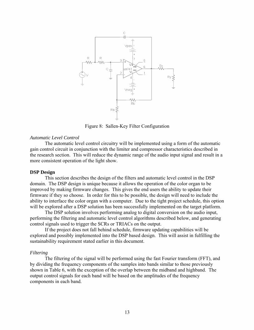
Analog Design Filtering Active filters were chosen to implement the low, mid, and high frequency band divisions with frequency ranges shown in Table 6. These divisions are realized using lowpass, bandpass, and highpass filters. Each filter design is not to exceed the 4th order due to stability concerns and board topology limitations. The bandpass filter will be implemented using a lowpass filter cascaded with a highpass filter due to observed performance issues with a true bandpass filter. Each filter will be implemented using the Sallen Key configuration shown in Figure 8.
Table 6: Frequency Ranges for Low, Mid, and High Bands
Band Range (Hz) Low 0 – 225 Mid 225 – 3000 High 2500 – 20,000
13
Figure 8: Sallen-Key Filter Configuration
Automatic Level Control The automatic level control circuitry will be implemented using a form of the automatic gain control circuit in conjunction with the limiter and compressor characteristics described in the research section. This will reduce the dynamic range of the audio input signal and result in a more consistent operation of the light show. DSP Design This section describes the design of the filters and automatic level control in the DSP domain. The DSP design is unique because it allows the operation of the color organ to be improved by making firmware changes. This gives the end users the ability to update their firmware if they so choose. In order for this to be possible, the design will need to include the ability to interface the color organ with a computer. Due to the tight project schedule, this option will be explored after a DSP solution has been successfully implemented on the target platform. The DSP solution involves performing analog to digital conversion on the audio input, performing the filtering and automatic level control algorithms described below, and generating control signals used to trigger the SCRs or TRIACs on the output. If the project does not fall behind schedule, firmware updating capabilities will be explored and possibly implemented into the DSP based design. This will assist in fulfilling the sustainability requirement stated earlier in this document. Filtering The filtering of the signal will be performed using the fast Fourier transform (FFT), and by dividing the frequency components of the samples into bands similar to those previously shown in Table 6, with the exception of the overlap between the midband and highband. The output control signals for each band will be based on the amplitudes of the frequency components in each band.

14
Automatic Level Control Automatic level control will be implemented using the results of the FFT. The amplitudes in each of the three frequency bands will be measured and used to determine if the lights should be triggered and at what intensity they should be triggered.

15
PROJECT SCHEDULE AND COST ESTIMATION Project Schedule Tables 7 – 9 outline the project schedule for fall, winter, and spring quarters. Refer to Appendix C for the Gantt charts. A task with a duration of zero days signifies a project milestone or other important date.
Table 7: Fall Quarter Schedule
Fall Quarter TASK START END DURATION Administrative 09/08/06 10/27/06 49d Team Charter Development 09/08/06 09/15/06 7d Problem Identification 09/15/06 09/22/06 7d Block Diagram 09/22/06 09/29/06 7d Constraints 10/06/06 10/20/06 14d Project Summary 10/06/06 10/13/06 7d Gantt Chart 10/06/06 10/13/06 7d Peer Evaluation 10/13/06 10/13/06 0d Commercial Product Comparison 10/16/06 10/21/06 5d Decision Matrices 10/20/06 10/26/06 6d Proposal 10/21/06 10/27/06 6d Proposal Presentation 10/27/06 11/02/06 6d Proof of Concept 09/18/06 11/17/06 60d Analog Filtering 09/18/06 11/17/06 60d Line Level Input 09/18/06 11/17/06 60d Automatic Level Control 09/18/06 11/17/06 60d DSP Research 09/18/06 11/17/06 60d MatLab Algorithms 09/18/06 11/17/06 60d DSP Platform Selection 11/15/06 11/15/06 0d
Table 8: Winter Quarter Schedule
Winter Quarter TASK START END DURATION Prototype - First Iteration 11/27/06 02/23/07 88d Peer Evaluation 01/12/07 01/12/07 0d Evaluate DSP Solution 01/19/07 01/19/07 0d

16
Table 9: Spring Quarter Schedule
Spring Quarter TASK START END DURATION Prototype - Second Iteration 03/05/07 04/20/07 46d Peer Evaluation 04/06/07 04/06/07 0d FE Exam 04/21/07 04/21/07 0d Administrative 04/22/07 05/10/07 18d Poster 04/22/07 04/26/07 4d IEEE Poster Presentation 04/26/07 04/26/07 0d Final Report 04/23/07 05/04/07 11d Web Site 04/30/07 05/10/07 10d Final Presentation 05/04/07 05/08/07 4d
Cost Estimation Tables 10 and 11 detail the estimated development costs for this project. The prototype will be developed using parts available in-house. After development, additional costs may be incurred for the purchasing of necessary components. An estimated cost per unit will be determined after the prototype has been developed and will be presented in the final report. The total estimated development cost, including labor and resources, is US $19,100.
Table 10: Labor Cost
Term Hours Hourly Rate (US) Total (US)
Summer 52 $25.00 $1,300.00 Fall 200 $25.00 $5,000.00 Winter 250 $25.00 $6,250.00 Spring 250 $25.00 $6,250.00 Total $18,800.00
Table 11: Resource Cost
Description Price (US) DSP Evaluation Board w/ IDE $300.00
Total $300.00

17
CONCLUSION
Animated Sound believes that there is a need for the ultimate color organ. Many of today’s commercially available color organs fall short in several areas, making consumers with high-end stereo equipment desire a better product. The design team believes that it can significantly improve the existing technology and use it to create the ultimate color organ.

18
Appendices
Appendix A: Commercially Available Color Organs Appendix B: Decision Matrix Criteria Appendix C: Project Gantt Charts Appendix D: Bibliography Appendix E: Team Member Resumes

19
Appendix A – Commercially Available Color Organs Velleman 3 Channel Light Organ Kit Manufacturer: Velleman, INC. Mfg #: K807 Price: $49.95 (US) Features:
− Microphone input − Sensitivity adjustment for each channel − Master sensitivity adjustment − LED indicators − Low, mid, and high channels − 80 piece kit − Translucent Case − Powered by 110 VAC − 2 A per channel max load
Drawbacks: − Picks up ambient noise − Passive filters − Constant manual sensitivity adjustment needed for music with wide dynamic range
Source: Jameco [16] 3 Channel Color Organ Kit Manufacturer: Chaney Electronics Mfg #: C4530 Price: $15.75 (US) Features:
− Speaker level input − Isolation transformer − Low, mid, and high channels − 200 W max output per channel − Master sensitivity control − 110 VAC operation
Drawbacks: − Passive filters − No individual channel control − Case not included − Constant manual sensitivity adjustment needed for music with wide dynamic range
Source: Electronic Goldmine [17]
20
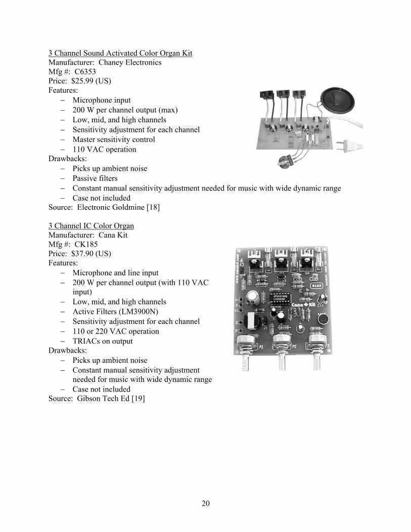
3 Channel Sound Activated Color Organ Kit Manufacturer: Chaney Electronics Mfg #: C6353 Price: $25.99 (US) Features:
− Microphone input − 200 W per channel output (max) − Low, mid, and high channels − Sensitivity adjustment for each channel − Master sensitivity control − 110 VAC operation
Drawbacks: − Picks up ambient noise − Passive filters − Constant manual sensitivity adjustment needed for music with wide dynamic range − Case not included
Source: Electronic Goldmine [18] 3 Channel IC Color Organ Manufacturer: Cana Kit Mfg #: CK185 Price: $37.90 (US) Features:
− Microphone and line input − 200 W per channel output (with 110 VAC
input) − Low, mid, and high channels − Active Filters (LM3900N) − Sensitivity adjustment for each channel − 110 or 220 VAC operation − TRIACs on output
Drawbacks: − Picks up ambient noise − Constant manual sensitivity adjustment
needed for music with wide dynamic range − Case not included
Source: Gibson Tech Ed [19]
21
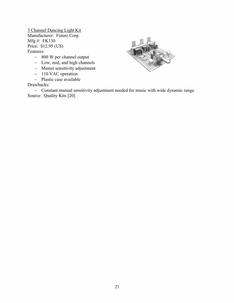
3 Channel Dancing Light Kit Manufacturer: Future Corp Mfg #: FK130 Price: $12.95 (US) Features:
− 800 W per channel output − Low, mid, and high channels − Master sensitivity adjustment − 110 VAC operation − Plastic case available
Drawbacks: − Constant manual sensitivity adjustment needed for music with wide dynamic range
Source: Quality Kits [20]

22
Appendix B – Decision Matrix Criteria This appendix outlines the criteria and weighting for each of the decision matrices. Tables 12 – 14 provide a visual representation of the criteria weighting. Analog vs. DSP - Criteria
1. Accuracy a. How accurately will the system function? b. What is deemed acceptable? c. Weight: 0-100…High values are best.
2. Development Time a. How long will it take to construct the system? b. Troubleshooting concerns in each system. c. Weight: 0-50…High values are best.
3. Overall Cost a. What is the cost that it will take to build one board? b. Factor in parts and labor time. c. Weight: 0-50…High values are best.
4. Number of Parts a. What is the total number of parts that will be required to make the system work? b. This deals with the real-estate on the circuit board, the end size. c. Weight: 0-25…High values are best.
5. Scalability a. How able is the system to handle upgrades? b. Weight: 0-25…High values are best.
6. Manufacturability a. How easy will it be to manufacture this product? b. Take into consideration number of parts, programming needs, labor. c. Weight: 0-25…High values are best.
Table 12: Weighted Analog vs DSP Decision Matrix
Criteria
Implementation Method
System Accuracy
Development Time
Overall Cost
Number of Parts Scalability Manufacturability Total
Analog 0 50 0 0 0 0 50 DSP 100 0 50 25 25 25 225
Filtering - Criteria
1. Approximation of Filter a. How well does the filter respond? (Roll off issues in implementation) b. How well defined are the pass band and stop band regions? c. Weight: 0-100…High values are best.
2. Development Time a. How much time will it take to design and construct/program these filters?

23
b. Are there considerable troubleshooting concerns (i.e. getting lower tolerance parts for analog filters and constructing the models)?
c. Weight: 0-50…High values are best. 3. Overall Cost – What is the overall cost to make three channels of filters?
a. How much do the parts cost that are necessary for the construction of the filters? b. Weight: 0-50…High values are best.
4. Manufacturability a. How easy will it be to mass produce this product?
i. Consider programming needs, mounting analog parts, etc. b. Will it be a quick process? c. Weight: 0-25…High values are best .
5. Sustainability a. How durable will the product be? b. Will the number of parts and their respective lifecycles affect the performance of
the product? c. Weight: 0-25…High values are best.
Table 13: Weighted Filtering Decision Matrix
Criteria
Types of Filtering Approximation Development Time
Overall Cost Manufacturability Sustainability Total
Passive Filters 0.00 50.00 50.00 8.33 0.00 108.33 Active Filters 33.33 33.33 0.00 0.00 8.33 75.00
Digital Filtering 66.66 0.00 16.67 16.67 16.67 116.67 FFT & Algorithms 100.00 16.67 33.33 25.00 25.00 200.00
Output Control - Criteria
1. System Functionality a. What is the dynamic range of the output? b. Weight: 0-50…High values are best.
2. Power-Handling Capability a. Can the component handle a power output up to 200 W? b. Weight: 0-50…High values are best.
3. Supporting Hardware a. How much supporting circuitry is needed for the device to function? b. Less circuitry is assigned higher points. c. Weight: 0-50…High values are best.
Table 14: Weighted Output Control Decision Matrix
Criteria
Type of Output System Functionality
Power-Handling Capability
Supporting Hardware Total
SCR 0 25 50 75 TRIAC 50 25 0 75

24
Appendix C – Project Gantt Charts
Appendix C
Project Gantt Charts

25

26

27
Appendix D – Bibliography [1] “The Ins and Outs of Interfacing Analogue and Digital Equipment.” May 2000.
<http://www.soundonsound.com/sos/may00/articles/digital.htm>.
[2] “Decibel.” 20 March 2006. <http://www.sizes.com/units/decibel.htm>.
[3] “How to Digitize Your Records and Tapes To Make Audio CDs and MP3 Files.” 22 February 2006. <http://www.covingtoninnovations.com/audio/digitizing/
index.html#levels>.
[4] Finelli, Patrick M. Sound for the Stage. New York : Drama Book Publishers, 1989.
[5] “Sound Performance Lab.” 2002. <http://www.spl-usa.com/pdf/PI_E/2048_PI_E.pdf>.
[6] Wikipedia – “Audio Level Compression.” 16 October 2006. <http://en.wikipedia.org/wiki/ Audio_level_compression>.
[7] Rudolph, Barry. “Understanding Compressors and Compression.” 1 January 1999. <http://mixonline.com/mag/audio_understanding_compressors_compression/index.html>
[8] Ciletti, Eddie. “An Overview of Compressor / Limiters And Their Guts.” 15 May 2003. <http://www.tangible-technology.com/dynamics/comp_lim_ec_dh_pw2.html>.
[9] Wikipedia – “Automatic Gain Control.” 5 August 2006. < http://en.wikipedia.org/wiki/ Automatic_gain_control>.
[10] “Effective AGC Amplifier Can Be Built At A Nominal Cost.” 3 August 1998. <http://www.elecdesign.com/Articles/Print.cfm?AD=1&ArticleID=6272>.
[11] “Audio Limiters.” Media College. <www.mediacollege.com/audio/processing/limiter/>/
[12] “P1 Audio Processor White Paper.” May 2003. <http://home.btconnect.com/ssa/ whitepaper/whitepaper.htm>.
[13] “The Silicon-Controlled Rectifier (SCR).” All About Circuits. <http://www.allaboutcircuits.com/vol_3/chpt_7/5.html>.
[14] “The TRIAC.” All About Circuits. <http://www.allaboutcircuits.com/vol_3/chpt_7/6.html>.
[15] “Simulink 6.5 Product Description.” The MathWorks. <http://www.mathworks.com/ products/simulink/description1.html>.
[16] Jameco. Online Catalog. Velleman Inc #K8017. <http://www.jameco.com/webapp/wcs/ stores/servlet/ProductDisplay?langId=-1&storeId=10001&catalogId=10001& productId=131684>.
[17] Electronic Goldmine. Online Catalog. Chaney Electronics. #C4530. <http://www.goldmine- elec-products.com/prodinfo.asp?number=C4530>.
[18] Electronic Goldmine. Online Catalog. Chaney Electronics. #C6353. <http://www.goldmine- elec-products.com/prodinfo.asp?number=C6353>.
[19] Gibson Tech Ed. Online Catalog. Cana Kit #CK185. <http://www.gibsonteched.com/ product3329.html>.
[20] Quality Kits. Online Catalog. Future Corp #FK130. <http://store.qkits.com/moreinfo.cfm/ FK130>.

28
Appendix E – Team Member Resumes
Appendix E
Team Member Resumes