the two tinned tunas kit this is qrpme’s version of the
TRANSCRIPT

The Two Tinned Tunas Kit
This is QRPme’s version of the illustrious Tuna Tin 2 as designed by Doug DeMaw and
resurrected by Doug Hendricks and Norcal.

has all this stuff…

and comes in many flavors….depending on the time of year and whims of those krazy kitters at
QRPme. You can find all the label designs on the CDrom. Print out your favorite design and use
that if you prefer.
Visit
www.megalink.net/~w1rex/QRPmeor
www.QRPme.com
to check out their latest version.

And the adventure begins….

Organize your parts….
I received this most excellent antistatic foam sheet when I ordered some samples from Analog
Devices. The samples came packed in a very nice box with this sheet. I keep the sheet and
parts for the kit in progress in the sample box to keep them all in one place.
(OK one observant builder caught me….there are 15 caps in the above photo but only 14 caps in the Two Tinned Tunas circuit...)
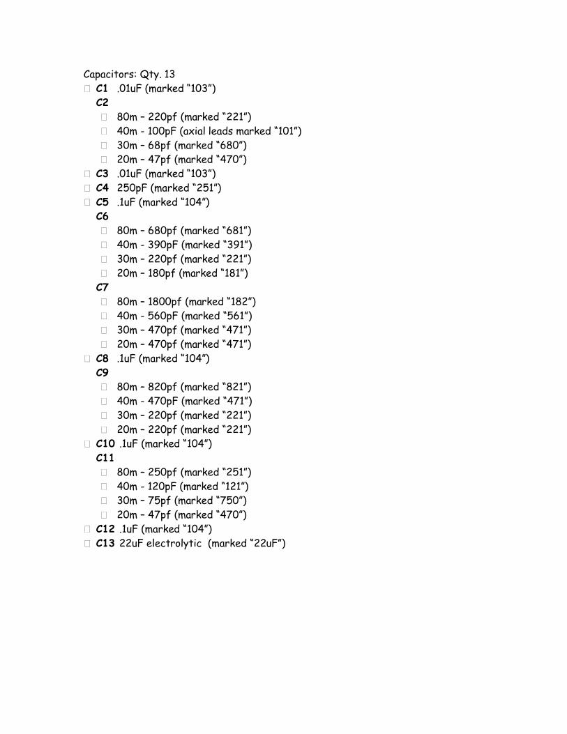
Capacitors: Qty. 13� C1 .01uF (marked “103”)
C2� 80m – 220pf (marked “221”)� 40m - 100pF (axial leads marked “101”)� 30m – 68pf (marked “680”)� 20m – 47pf (marked “470”)
� C3 .01uF (marked “103”)� C4 250pF (marked “251”)� C5 .1uF (marked “104”)
C6� 80m – 680pf (marked “681”)� 40m - 390pF (marked “391”)� 30m – 220pf (marked “221”)� 20m – 180pf (marked “181”)C7� 80m – 1800pf (marked “182”)� 40m - 560pF (marked “561”)� 30m – 470pf (marked “471”)� 20m – 470pf (marked “471”)
� C8 .1uF (marked “104”)C9� 80m – 820pf (marked “821”)� 40m - 470pF (marked “471”)� 30m – 220pf (marked “221”)� 20m – 220pf (marked “221”)
� C10 .1uF (marked “104”)C11� 80m – 250pf (marked “251”)� 40m - 120pF (marked “121”)� 30m – 75pf (marked “750”)� 20m – 47pf (marked “470”)
� C12 .1uF (marked “104”)� C13 22uF electrolytic (marked “22uF”)

Resistors: Qty. 9� R1 4.7K ohms (yellow-violet-red)� R2 47K ohms (yellow-violet-orange)� R3 220 ohms (red-red-brown)� R4 100 ohms (brown-black-brown)� R5 1K ohms (brown-black-red)� R6 8.2K ohms (gray-red-red)� R7 6.8 ohms (blue-gray-gold)� R8 1K ohms (brown-black-red)� R9 470 ohms (yellow-violet-brown)Miscellaneous Hardware� L1 22uH choke 7 turns on FT37-43 toroid core (black donut)
L2� 80m – 23 turns on T37-2 toroid core (red donut)� 40m - 19 turns on T37-6 toroid core (yellow donut)� 30m - 20 turns on T37-6 toroid core (yellow donut)� 20m - 13 turns on T37-2 toroid core (red donut)L3� 80m – 26 turns on T37-2 toroid core (red donut)� 40m - 19 turns on T37-6 toroid core (yellow donut)� 30m - 17 turns on T37-6 toroid core (yellow donut)� 20m - 13 turns on T37-6 toroid core (yellow donut)
� Q1 MP2N2222A NPN transistor (epoxy cased TO-92)� Q2 2N2222A NPN transistor (metal can TO-18)� Q2 2N3906 PNP transistor (epoxy cased TO-92)� P1 100 ohm potentiometer� T1 10 turns (primary) and 5 turns (secondary) on FT37-43 toroid (black)� X1 crystal, 80m=3.560Mhz, 40m=7.040MHz, 30m=10.116Mhz or
20m=14.060Mhz � S1 SPDT transmit/receive switch� SIP Socket strip 8 pin strip for xtal and transistor sockets � J1 1/8” jack, mono, chassis mount� J2, J3, J4 RCA phono jacks� Red Magnet wire: 4-feet of red wire � PCB Printed Circuit Board
� Sandpaper
� 1/8 x 1 ¼” stove bolt and nut
� Solder
� 2 pieces hookup wire

Review the schematic to see what is in store. Print out a copy of the manual from the CDRom.
Detailed instructions are there. This file is a quick tutorial that guides you while you assemble your kit. It is advisable to read all the way through this
Step by Step tutorial (at least once!) to get acomplete idea of the total project.
Note the table in the bottom center of the schematic listing the components of the Two
Tinned Tunas kit that change for different bands.

Review the layout diagram once again. Can you find:
C1 through C11?(trick question)R1 through R9?
L1, L2,L3, and T1Pads marked:
To S1To J1
To Ground

Review the wiring diagram for the external jacks and switch…

Make a crystal socket from the SIP socket strip by cutting off the center pin of a 3 pin segment.

Make a transistor socket from the remaining SIP socket strip by cutting off 3 single socket pins.

Install the sockets at X1 and Q2. Lay a stiff sheet of any material over the sockets and flip the
board over to solder the socket pins. Make sure the pins are standing straight after soldering.
OR

You can use a capacitor, or in this case an extra crystal, as a holder for the socket pins while
soldering. Simply insert the component leads into the socket, then insert the socket pins into the
PCB hole and hold them in place using the component as a handle. Solder the socket pins in
place and remove the component.

Install Q2 a TO-18 2N2222A, into the socket, aligning the tab on the transistor with the tab
marked on the silkscreen. Now double check the orientation of transistors Q1 a TO-92 2N2222A
and Q3 a TO-92 PN3906. The flat side of Q1 is on the B (Base) mark while the flat side of Q3 is
opposite the B side.

Install transistor Q1, a TO-92 PN2N2222A and check that the flat side of the transistor is oriented towards the B reference on the
silkscreen.
Install transistor Q3, a TO-92 2N3906 and check that the flat side of the transistor is oriented away
from the B reference on the silkscreen.

Bend the leads slightly after you insert the transistor leads in the holes to keep them from
falling out when you turn the board over to solder them. Solder the 6 leads one at a time,
alternating between the two transistors to keep the heat from building up inside the transistors.
Snip off the excess leads.
The empty can makes an excellent board holder when soldering the parts.

Install C1, marked 103M, bend the leads slightlybelow the board, turn the board over, solder and snip off the excess leads. The 103M is a code for
the value and temperature rating of the capacitor. Read the 1st 2 digits (10) and add the 3rd digit in zeros yielding 10,000 pf. The M is a
code for this capacitor indicating a Z5U temperature range (+/- 20% from 10˚C to +85˚C).
Way too much info here right??

Now install C2, marked 101 ( 100 pf ) so small you need a magnifying glass to read it. It is also a different body style (axial) than C1 (disc). You can speed up the process by installing several parts, bending the leads of each part as it is installed,
and solder the leads after 2 or 3 parts are installed….
NOTE: If you have a Two Tinned Tunas kit for another band, C2 will be a different value:
BAND= 80m 40m 30m 20mC2 (in pf) 220 100 68 47

Now install C3, marked 103M ( 10,000 pf )

And C4, marked 251 ( 250 pf )

And C5, marked 104M ( 100,000 pf or .1uf ). There is no silkscreen marking ‘C5’. The outline
is marked just to the left of Q2.

Now C6, marked 391 ( 390 pf )
NOTE: If you have a Two Tinned Tunas kit for another band, C6 will be a different value:
BAND= 80m 40m 30m 20mC6 (in pf) 680 390 220 180

And C7, marked 561 ( 560 pf )
NOTE: If you have a Two Tinned Tunas kit for another band, C7 will be a different value:
BAND= 80m 40m 30m 20mC7 (in pf) 1800 560 470 470

And C8, marked 104M ( .1 uf )

And C9, marked 471M ( 470 pf )
NOTE: If you have a Two Tinned Tunas kit for another band, C9 will be a different value:
BAND= 80m 40m 30m 20mC7 (in pf) 820 470 220 220

And C10 ( 104 M ) a .1 uf capacitor.

Capacitor C11 will be installed later, so we will move on to C12 ( 104 M ) a .1 uf capacitor.

Install R1, color coded yellow violet red. Note the little circle and bar on the circuit silkscreen. This
indicates that the resistor should stand on end with the body mounted over the circle and the
lead bent over and inserted in the bar hole.
Here are the 2 types of resistor markings and their designated mounting styles.
Horizontal Vertical

Skip this part if you know the code…Black=0
brown = 1red=2
orange=3yellow=4green=5blue=6
violet=7gray=8white=9
resistor value is calculated from the codes same as a capacitor. Convert the 1st two colors to
numbers and add the 3rd value in zeros. So yellow violet red = 4700 ohms.

Install R2, marked yellow violet orange ( 47K )

And R3, marked red red brown ( 220 )

R4, marked brown black brown ( 100 )

R5, marked brown black red ( 1,000 or 1K )
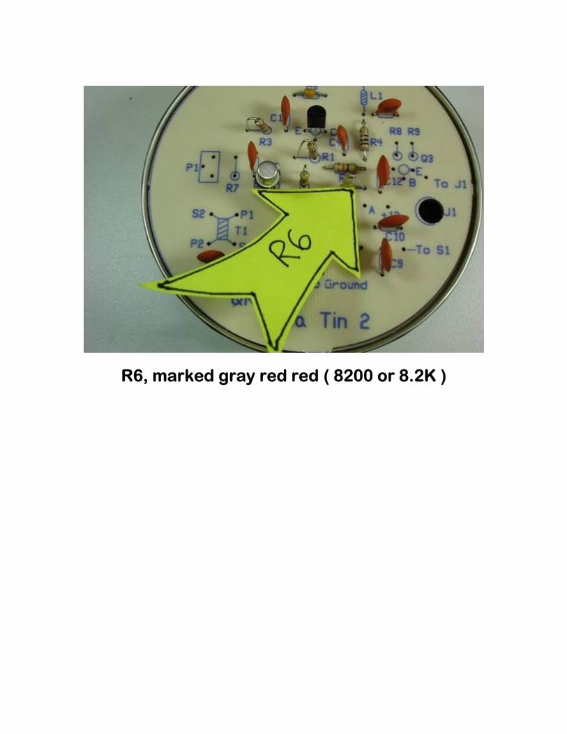
R6, marked gray red red ( 8200 or 8.2K )

And R7, marked blue gray gold ( 6.8 ohms )

Resistor R8, marked brown black red (1000 or 1K OHMS)

And the final resistor R9, marked yellow violet brown ( 470 ohms )

Now install potentiometer P1. NOTE: P1 is used to vary the power output of the final transistor Q2. Use caution when adjusting the pot as
you can easily burn up transistor Q2, which is why we are putting Q2 in a socket. You can obtain in excess of 1/2 watt of output power from Q2….if you properly heat
sink the transistor and use some forced ventilation.After soldering P1 into the circuit, measure the
resistance from the E terminal of Q2 to the groundplane. You should read close
to 100 ohms. If you get a lower reading, adjust pot P1
to obtain a maximum reading.Pot P1 is 100 ohms in SERIES with Q2 emitter resistor R7. Normal operation is with the
Typical potentiometers potentiometer set at themidpoint of 50 ohms.

Now for the toroids, these puppies aren’t quite as tricky as you hear. Every time the wire passes through the center it is counted as a turn. Different band versions of the Two Tinned Tunas have different toroid values:
Band L2 turns:core L3 turns:core80m 23 turns:red 26 turns:red40m 19 turns:yellow 19 turns:yellow30m 20 turns:yellow 17 turns:yellow20m 13 turns:red 13 turns:yellow

They should look a lot like this…
Of course, the number of turns, length of magnet wire used and the color of the toroid will vary
depending upon the band you are building the kit for!

L1 is 7 turns on one of the black cores…use an 8” piece of magnet wire

Carefully scrape the insulation off the leads withan Xacto knife or other sharp bladed instrument. Keep the blade perpendicular to the wire so that
you don’t nick, gouge, or accidentally cut the wire off.

Nice bright copper is what you need to solder. Any insulation, loose or solid, will result in an
uneven solder joint. A few very light swipes with sandpaper should wipe away any loose crud. You
might try scraping and sanding a plain piece of magnet wire, practicing your technique, before
you actually try it on a finished toroid….

Place L2, standing up, solder carefully and then spread out the turns evenly

After soldering, you should distribute the turns evenly around the toroid. L2 should look a lot like
this now…

And install L3

Now install L1 on the board

T1 is by far the trickiest thing to do and even it is not that tricky. Cut off an 8” piece of magnet wire and wind 10 turns evenly around the toroid and cut the leads off ‘short’ relatively speaking. The
‘short’ leads are the primary leads P1,P2. Using a 6” piece of magnet wire, now wind 5 turns around the toroid, starting at the same point you started
the primary winding and wind the wire around every other primary turn and cutting the leads off ‘long’. The ‘long’ leads are the secondary leads S1,S2. I use the uncut length of the leads to help me keep track of which leads are which when I
go to put them in the circuit board holes.
Transformer T1 has a 2:1 TURNS ratio which equals a 4:1 IMPEDANCE ratio

Now install transformer T1. Pay careful attention to which leads you put in which hole. P1 and S1 are the primary and secondary leads at one end of the windings. P2 and S2 are the leads at the
other end.

Now install C11, marked 121 ( 120 pf ) on the under side of the circuit board. C11 is soldered across the mounting pads of L3. Check the top
side silkscreen for the position of L3. Now transfer those reference points to the under side
of the board. You should be looking at holes 3 and 4, counting from the left, of the long
horizontal trace where all the low pass filter parts are mounted.
NOTE: If you have a Two Tinned Tunas kit for another band, C11 will be a different value:
BAND= 80m 40m 30m 20mC11 (in pf) 250 120 75 47

Familiarize yourself once again with the wiring diagram for what is external to the board and
mounted on the can…and how it translates into a real can…

Install the 1/8 “ jack at J1 and wire the side lug straight down to the pcb ground plane using a
piece of resistor lead.

Solder a short piece of hookup wire from the jack lug furthest away from the side lug, to the pad
directly below the jack. Then solder the side lug of the jack to the ground plane. Now clip off any
excess leads.

Peel off the sticker on the bottom of the can to reveal a mounting hole

Use an Xacto knife to carefully remove the label covering the jack and switch holes. The location
of the holes are indicated by the little stars on the label. The label should only be glued to itself, and NOT the can. You should be able to hold the can up in the light and look into the can at the hole locations. Rotate the label and center the stars for best fit BEFORE you cut through the holes.

Most QRPme tuna cans are uncoated steel and need no prep. Others might have an inner finish to protect the food contents. On coated cans,
sand off the ‘paint’ around the holes in order to have ‘good’ grounding on the connector’s lugsand mount the 3 RCA connectors in the holes
marked Ant, +12 and Rcvr

Bend the ground lugs out a little to make them easier to solder to…

Measure and cut 2 pieces of hookup wire to fit between the connectors. Twist one set of ends together and tin all ends. Solder the 3 ground lugs together. There is an old adage that says that a good electrical bond STARTS with a good mechanical bond. Make sure that the wire goes through the hole in the solder lug and is mechanically secure before you solder the connection.

Prepare the T/R switch… ‘test fit’ the switch and cut 3 pieces of hookup wire long enough to make the connections shown in orange in the picture below. Remove the switch from the can and solder the wires on the bench. Use care when soldering to the switch pins. Too much heat will melt the plastic body of the switch. Tin all the wire ends first. Thread the ends through the corresponding eyelet and bend over carefully with pliers. Wrap a rubber band around the handles of a small pair of needle nose pliers so that the jaws are sprung shut. Clamp the jaws on the leads of the switch between the solder eyelet and the plastic body. This ‘heat sink’ will shunt excess heat from soldering away from the plastic body! Now solder the wires carefully and QUICKLY!
Reinstall the T/R switch into the can. Now solder the left pin on the T/R switch to the center of the Rcvr connector. Solder the center pin of the T/R switch to the Ant connector center pin. The wire on the right pin on the T/R switch hangs loose and will attach to the circuit board…

Now add the power filter cap C13, marker 22 uF from Ant. Jack Ground lug (-lead) to +12 Jack
Center pin (+ lead)

Solder a short 5” ground wire from the Ant. connector ground lug to the circuit board hole marked ‘To Ground’. Likewise, solder the wire from the center of the +12 volt jack to the hole
marked ‘+12’. Solder the right lead coming off the T/R switch to the hole marked To S1.

Carefully stuff all the wire leads into the can while positioning the board onto the lip left by the easy open lid. You may have to sand or file off a nub on
the circuit board to make it fit smoothly. Insert the 1 1/4” bolt into the hole on the bottom and
find the hole drilled on the circuit board. Add the nut and gently tighten to clamp the board to the
tin.

And you’re finished! Now you can plug in the crystal, hook it up to a power supply, key and dummy load and check it out. See the original
TT2 manual for additional checkout information.