the thompson dowel-rest system modified for chrome … thompson dowel-rest system modified for...
TRANSCRIPT
The Thompson dowel-rest system modified for chrome-cobalt removable partial denture frameworks
Curtis M. Becker, D.D.S., M.S.D.,* Harold C. Campbell,** and Dee L. Williams, D.M.D.*** Univcrsity of Colorado, School of Dentistry, Denver, Colo.
T i l e purpose of this article is to present laboratory and mouth procedures for the construction of a modified Thompson dowel-rest removable partial denture using (1) prefabricated dies for the dowel- rests, (2) a chrome-cobalt removable partial denture framework, and (3) a ball clasp retention device.
LITERATURE REVIEW
The precursor to the Thompson dowel semipreci- sion attachment system was originated by Clark in 1938, as described by Rybeck? Clark advocated soldering Neurohr-Williams No. 2 shoes (Fig. I) into abutment restorations and using lingual clasp arms to engage mesial undercuts for primary retention. Thompson-~ 3 later modified Clark's at tachment system by placing the retention undercut directly on the fulcrum line, thus reducing the potential for abutment to rquing with distal-extension partial dentures. The Thompson dowel system and its advantages and disadvantages have been thoroughly discussed by numerous authors. 4"" Basic guidelines for dimensions of the dowel-rest have been stated by Koper (Fig. 2)?
The Thompson dowel retainer is a semiprecision retainer designed to provide built-in indirect reten- tion and stress-breaking without loss of cross-arch stabilization. The Thompson dowel-rest seat consists of two parts: the tapering recess and the well (Fig. 2). The lingual walls of the tapering recesses in the abutments should be parallel (Fig. 3). The bueeal walls of the recesses should flare to allow free movement with occlusal forces. The wells of" the retainers should be placed so that tile axial walls are
Read before the American Prosthodontic Society, Chicago, Ill. *Clinical Assistant Professor, Depar tment of Prosthodontlcs. **Certified Dental Laboratory Technician. ***Associate Professor and Chai rman, Depar tment of Occlu-
sion.
A
Fig. 1. A, The Neurohr-WiIliams No. 2 shoe and, paral- leling mandrel. B, The Neurohr-Williams No. 2 shoe and the mesial-lingual retentive clasp as advocated by Clark.
parallel to the fulcrum line (Figs. 2 and 3). The weils, in conjunction with retentive dimples (Fig. 2), provide retention of the removable partial denture, prevent distal movement o f the removable partial denture, and contribute to the indirect retention of the prosthesis. Tile design of the Thompson dowel retainer can be adapted to either mesial-extension or distal-extension bases.
MODIFICATIONS
Retention device and framework. Several au- thors ~. 8. a have stated or implied that the Thompson dowel design is the choice for mesial- and distal- extension removable partial dentures. However, there are several factors limiting the routine use of
384 APRIL 1978 VOLUME 39 NUMBER 4 0022-3913/7810439-0384500.80/0 �9 1978 The G. V. Mosby Co.

MODIFIED T H O M P S O N DOWEL-REST SYSTEM
Tapering ReCesa __ Well L ~ B
Fig. 2. The dimensions for the Thompson dowel-rest as advocated bY Koper.
I t .
A/ ,o ~ t
f t .
Line ~ e
!
Fig. 3. The design of the left and right side dowel-rests are different due to parallel lingual walls (A) and flaring buccal walls (B).
the Thompson dowel concept. An important limita- tion is the high cost of fabricating the partial denture framework in gold, as is advocated by most authors who .have described the Thompson dowel sys- tem.-"-s
A technique for reducing the cost has been described by Wands. I~ He advocates using a chrome- cobalt major connector to which the gold alloy dowel-rests are soldered. Pr imary retention is attained by using stainless steel ball clasps to engage the retention dimples. This concept (Fig. 4) has been incorporated into our modified technique and has been found to be a realistic approach to reducing costs. Disadvantages of the cast-gold retentive clasp advocated by other authors, "~-" such as dimple reten- tion wear and difficulty in adjustments and repair, are eliminated by the use of the wrought-wire ball clasp. Experirnentation has shown that the entire framework of dowel-rests and major connector can be accurately cast in chrome-cobalt as one piece (Fig. 5). This technique eliminates the need for multiple casting and soldering techniques.
Rest seat fabrication. Another limitation to the general use of the Thompson dowel system is the extreme difficult)" in hand-carving the dowel-rest seats. Attempts to construct a standard die of the do?,vel-rest from a previously handcar~,ed dowel-resi seat have been successful. The standard dowel-rest was cast in chrome-cobalt, and a surveyor was used
Fig. 4. A Thompson dowel removable partial denture system using a chrome-cobalt major connector (A) with gold alloy dowel-rests (B) soldered to the major connec- tor. A ball clasp (C) is used for retention.
to wax-up rest seats in successive abutment retainers (Fig. 6). A right and left standard die are utilized to confor,n to the design of the dowel-rest as suggested by Koper s (Fig. 3). When the dowel-rests are prop- erly aligned tile lingual walls of the rest seats in the right and left abutments will be parallel. This alignment will allow for stress-breaking of occlusal forces applied to the distal-extension base and at the same time will resist cross-arch tipping forces. An optional lingual reciprocal arm is often added to the framework to insure proper cross-arch reciprocation
THE ]OURNAL OF PROSTHETIC DENTISTRY 385
BECKER, CAMPBELL, AND WILLIAMS
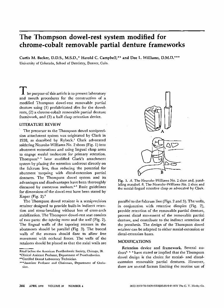
Fig. 5. A Thompson dowel removable partial denture with the dowel-rests and the major connector cast in one piece using chrome-cobalt metal. A 0.8 mm ball clasp retention device is attached securely to the denture base retention guide of the partial denture framework with autopolymerizing acrylic resin.
B
D
W o II " - - ~
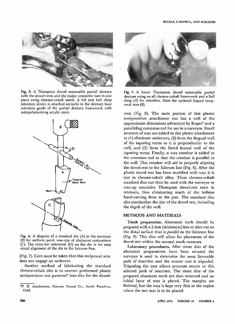
Fig. 6. A diagram of a standard die (A) in the surveyor (B) for uniform quick wax-ups of abutment restorations (C). The cross-bar extension (D) on the die is for easy visual alignment of the die to the fulcrum line.
(Fig. 7). Care must be taken that this reciprocal a rm does not engage an undercut .
Another method of fabricat ing the s tandard chrome-cobalt dies is to convert preformed plastic semiprecision rest patterns* into 'dies for the dowel-
*P. D. attachments, Natoma Dental Go., South Pasadena, Calif.
Fig. 7. A lower Thompson dowel removable partial denture using an all chrome-cobalt framework and a ball clasp (A) for retention. Note the optional lingual recip- rocal arm (B).
rests (Fig. 8). Tile male portion of this plastic semiprecision a t t achment rest has a well of the approximate dimensions advocated by Koper ~ and a paralleling extension rod for use in a surveyor. Small amounts of wax are added to this plastic a t t achment to (I) eliminate undercuts , (2) form the lingual wall of the tapering recess so it is perpendicular to the well, and (3) form the flared buccal wall of the tapering recess. Finally, a wax crossbar is added to the extension rod so that the crossbar is parallel to the well. This crossbar will aid in properly al igning the dowel-rest to the fulcrum line (Fig. 6). After the plastic dowel rest has been modified with wax it is cast in chrome-cobal t alloy. These chrome-cobal t s tandard dies can then be used with tile surveyor to wax-up successive T h o m p s o n dowel-rest seats in retainers, thus el iminat ing much of the tedious hand-carving done in the past. The s tandard dies also standardize the size of the dowel rest, including the depth of the well.
M E T H O D S A N D MATERIALS
Tooth preparat ion. Abu tmen t teeth should be prepared with a 2 m m (min imum) box or slice cut on the distal surface that is parallel to the fulcrum line (Fig. 9). This slice will allow for placement of the dowel-rest within the normal tooth contours.
Labora tory procedures . After stone dies of the abu tment preparat ions have been secured the surveyor is used to determine the most favorable path of insertion and the master cast is tripoded. Tr ipoding the cast allows accurate return to this selected path Of insertion. The stone dies o f the prepared abu tment teeth are then removed and an initial layer of wax is placed. The margins are finished, but the wax is kept very thin in the region where the rest seat is to be placed.
3 8 6 APRIL 1978 VOLUME 39 NUMBER 4
MODIFIED THOMPSON DOWEL-REST SYSTEM
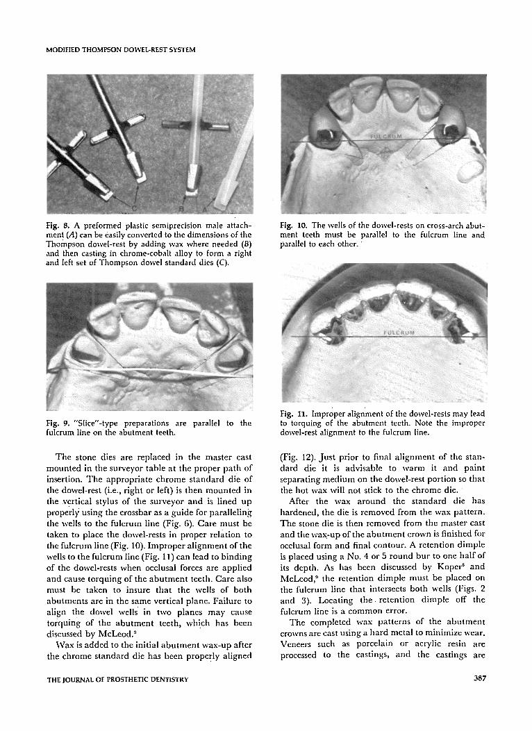
Hg. 8. A preformed plastic semiprecision male attach- ment (A) can be easily converted to the dimensions of the Thompson dowel-rest by adding wax where needed (B) and then casting in chrome-cobalt alloy to form a right and left set of Thompson dowel standard dies (C).
Fig. 10. The wells of the dowel-rests on cross-arch abut- ment teeth must be ~arallel to the fulcrum line and parallel to each other.
Fig. 9. "Slice"-type preparations are fulcrum line on the abutment teeth.
parallel to the Fig. 11. Improper alignment of the dowel-rests may lead to torquing of the abutment teeth. Note the improper dowel-rest alignment to the fulcrum line.
The stone dies are replaced in the master cast mounted in the surveyor table at the proper pat h of insertion. The appropria te chrome s tandard die of the dowel-rest (i.e., r ight or left) is then moun ted in the vertical stylus of the surveyor and is lined up properly using the crossbar as a guide for paralleling tile wells to the fulcrum line (Fig. 6). Care must be taken to place the dowel-rests in proper relation to the fulcrum line (Fig. 10). Improper a l ignment of the wells to the fulcrum line (Fig. 11) can lead to b inding of the dowel-rests when occlusal forces are applied and cause torquing of the abu tmen t teeth. Care also must be taken to insure that the wells of both abutments are in the same vertical plane. Failure to align the dowel wells in two planes may cause torquing of the abu tment teeth, which has bccn discussed by McLeod. 9
Wax is added to the initial abu tmen t wax-up after tile chrome s tandard die has been properly aligned
(Fig. 12). Jus t prior to final a l ignment of the stan- dard die it is advisable to warm it and paint separating medium on the dowel-rest port ion so that tile hot wax will not stick to the chrome die.
After the wax a round the s tandard die has hardened, the die is removed from the wax pattern. The stone die is then removed from the master cast and the wax-up of the abu tmen t crown is finished for occlusal form and final contour. A retention dimple is placed using a No. 4 or 5 round bur to one half of its depth. As has been discussed by Koper s and McLeod, 9 the retention dimple must be placed on the fulcrum line that intersects both wells (Figs. 2 and 3). Locat ing t i l e retention dimple off the fulcrum line is a c o m m o n error.
The completed wax patterns of the abu tmen t crowns are cast using a hard metal to minimize wear. Veneers such as porcelain or acrylic resin are processed to the castings, and the castings are
THE JOURNAL OF PROSTHETIC DENTISTRY 387

BECKER, CAMPBELL, AND WILLIAMS
Fig. 12. A standard die is used on the surveyor to wax-up a Thompson dowel-rest abutment restoration. Note the correct alignment of the cross bar on the die to the fulcrum line of the master cast.
Fig. 14. Under specific situations the retentive ball clasp can be omitted and a retentive dimple clasp can be cast with the chrome-cobalt framework. This design is a compromise as far as wear, adjustment, and repair are concerned.
Fig. 13. The chrome-cobalt partial denture framework is fabricated from a master cast (A) containing the abutment restorations. A designed diagnostic cast (B) is also sent to the laboratory.
adjusted to fit properly in the patient 's mouth . A "pick-up" or remount impression is advisable at this point, as is cus tomary with m a n y a t t achment techniques. '''~3 The east poured, from this impres- sion helps insure proper paralleling of guiding planes When the remount cast with abu tmen t castings is placed On the surveyor. The guiding planes can be refined with a handpiece a t tached to the vertical stylus of the surveyor.
The remount cast with the refined abu tmen t castings is sent to the dental laboratory with proper instructions for fabrication o f the chrome-cobal t partial denture framework (Fig. 13). W h e n the chrome-cobal t partial denture framework has been completed a 0.8 m m ball clasp* is contoured and at tached to the retention framework over the ridge
*Rocky Mountain Metal Products Co., Denver, Colo.
Fig. 15. The altered-cast procedure is essential for predictable tissue support with distal-extension Thomp- son dowel removable partial dentures.
with autopolymeriz ing acrylic resin (Fig. 5). Care must be taken tO a t tach the ball clasp firmly in at least two places to prevent its dis lodgment dur ing processing. I f the ball clasp should be dislodged or if the ball clasp should break in the future, it is a Simple procedure to uncover it in the acrylic resin and reposition or replace the ball clasp using more autopolymerizing acrylic resin.
Occasionally it ma y be undesirable to use the ball clasp for retention because of its bulk. This may occur in the maxil lary arch when the abu tmen t teeth are in an extreme anterior position, or it may occur with a maxillary unilateral distal-extension remov- able partial denture when a pontic will receive the dowel-rest. In these specific situations the retentive clasp a rm can be cast in chrome-cobal t alloy along with the dowel-rests as part of tile f ramework (Fig. 14). The major disadvantages to casting tile retentive
388 APRIL 1978 VOLUME 39 NUMBER 4
MODIFIED THOMPSON DOWEL-REST SYSTEM
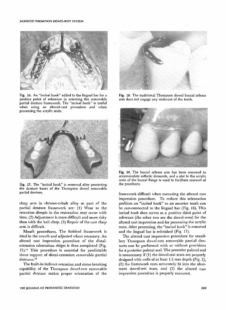
Fig. 16. An "incisal hook" added to the lingual bar for a positive point of reference in orienting the removable partial denture framework. The "incisal hook" is useful when using an altered-cast procedure and when processing the acrylic resin.
Fig. 17. The "incisal hook" is removed after processing the denture bases of the Thompson dowel removable partial denture.
clasp arm in chrome-cobalt alloy as part of the partial denture framework are: (1) Wear to the retention dimple in the restoration may occur with time. (2) Adjustment is more difficult and more risky than with the ball clasp. (3) Repair of the cast clasp arm is difficult.
Mouth procedures. The finished framework is tried in the mouth and adjusted where necessary. An altered cast impression procedure of the distal- extension edentulous ridges is then completed (Fig. 15). 14 This procedure is essential for predictable tissue support of distal-extension removable partial dentures. '5
The built-in indirect retention and stress-breaking capability of tile Thompson dowel-rest removable partial denture makes proper orientation of the
Fig. 18. The traditional Thompson dowel buccal release arm does not engage any undercut of the tooth.
Fig. 19. The buccal release arm has been removed t o accommodate esthetic demands, and a slot in the acrylic resin of the buccal flange is used to facilitate removal of the prosthesis.
framework difficult When executing the altered cast impression procedure. To reduce this orientation problem an "incisal hook" to an anterior tooth can be cast-connected to the lingual bar (Fig. 16). This incisal hook then serves as a positive third point of reference (the other two are the dowel-rests) for the altered cast impression and for processing tile acrylic resin. After processing, the "incisal hook" is removed and the lingual bar is refinished (Fig. 17).
The altered cast impression procedure for maxil- lary Thompson dowel-rest removable partial den- tures can be performed with or without provisions for a posterior palatal seal. Tile posterior palatal seal is unnecessary if (1) the dowel-rest seats are properly designed with wells of at least 1.5 mm depth (Fig. 2), (2) the framework rests accurately fit into the abut- ment dowel-rest seats, and (3) tile altered cast impression procedure is properly executed.
THE JOUI~NAL OF PROSTHETIC DENTISTRY 389

BECKER, CAMPBELL, AND WILLIAMS
Fig. 20. A unilateral Thompson dowel attachment system with a dowel-rest placed into a pontic (A). Note the proper relationship of the dowel-rests to the fulcrum line.
Fig. 21. The design of the release arm when a dowel-rest is placed in a pontic. Note that the release lever extends approximately 1 mm past the buccal tooth contour (A). This allows the patient to engage the release lever with a fingernail. A small loop (B) cast in the partial denture framework through which the ball clasp (C) can pass allows the ball clasp to flex away from the solder joint (D). This greatly reduces the possibility of breakage of the retentive ball clasp due to crystallization.
After the altered cast has been made the maxillo- mandibular jaw relations are recorded, artificial teeth are set up, and an esthetic try-in is completed. The maxil lomandibular relationships are verified at the try-in appointment, and the prosthesis is then processed. At the placement appointment the processed denture is remounted on a semiadjustable articulator and the occlusion is corrected. Minor adjustment of the retentive ball clasp may also be required.
Patient instruction as to proper insertion and removal of tile Thompson dowel-rest removable partial denture is done at the placement appoint-
Fig. 22. A unilateral Thompson dowel removable partial denture using a dowel-rest on one side and a cast circumferential clasp on the other side. This combination is feasible when the fulcrum line can be made to pass through the retentive segment of the buccal clasp arm.
ment. Koper q recommends tile use of a buccal arm "release lever" to facilitate the removal of the pros- thesis (Fig. 18). If a patient objects to the display of the metal of the release lever it may be omitted and a slot cut into the buccal flange just apical to the teeth (Fig. 19). The patient can then hook a fingernail into the slot for easy removal.
When placing a Thompson dowel-rest into a pontic, as with a unilateral removable partial denture (Fig. 20), the release lever must cross the occlusal surface of the pontic and extend about 1 mm beyond the buccal contour (Fig. 21). This allows the patient to engage the release lever with a fingernail.
The Thompson dowel system with a unilateral removable partial denture. When a fixed bridge is present on the side of the mouth opposite the distal- extension ridge, the dowel-rest can be incorporated into the pontic (Fig. 20). Proper attention must be given to the orientation of the dowel-rests in relation to the fulcrum line. A retentive ball clasp can be attached to tile framework with acrylic resin on the distal-extension side but must be soldered to the framework on the opposite side. There is potential for heat crystallization and resultant weakening of the wrought wire during soldering. To avoid break- age a small loop is cast in the removable partial denture framework. The ball clasp is then placed through the loop and soldered 2 to 3 mm away from tile loop (Fig. 20). This allows flexure away from the solder joint and greatly reduces the potential for fracture of the ball clasp.
The Thompson dowel system used with other
3 9 0 APRIL 1978 VOLUME 39 NUMBER 4

MODIFIED THOMPSON DOWEL-REST SYSTEM
clasp designs. Occasionally a Thompson dowel-rest may be used in conjunction with a conventional extracoronal clasp (Fig. 22). The conditions neces- sary for consideration of combining a conventional clasp and a Thompson dowel-rest are: (1) The fulcrum line is able to be manipulated so that it passes through the retentive segment of the conven- tional clasp arm (Fig. 22). (2) The abutment tooth on the distal-extension side of the mouth requires full coverage. (3) No restorations are required on the side of the arch opposite the distal-extension ridge.
DISCUSSION
The advantages of intracoronal attachments have been documented by several authors) ' 6. 8. ~ The specific advantages of the Thompson dowel-rest design are: (1) The intracoronal dowel-rest allows stresses to be maintained along the vertical axis of the tooth. (2~ Vertical and ro ta t iona l forces are directed closer to the bone support of the tobth than is possible with conventional occlusal rests. (3) Es- thetics is enhanced since no clasp arms are visible. (4) Stress-breaking is provided while still maintaining cross-arch stability. (5) The intracoronal dowel-rest allows for normal tooth contours. (6) The dowel-rest provides built-in guiding planes, indirect retention, and reciprocation. (7) The retentive clasp is placed directly on the fulcrum line.
Disadvantages of the Thompson dowel-rest system are: (1) Abutment teeth require restorations. (2) A high degree of skill is needed to fabricate the dowel- rest and removable partial denture framework. (3) Adequate crown length must be available. (4) The dowel-rest cannot be used on teeth with large pulps. (5) Cost is higher than with conventional removable partial dentures because of abutment restorations and a gold framework. (6) Adjustment of retention is difficult. (7) Wear to the retention dimple may occur with time.
Some disadvantages of the Thompson dowel-rest system have been reduced or eliminated by use of the chrome-cobalt removable partial denture framework and ball clasp retention device, as follows: (1) Cost is greatly reduced. (2) Simplicity in adjustment and repair and reduced wear to the retention dimple are provided by use of the ball clasp retention device. (3) Laborious and costly custom fabrication Of each dowel-rest is made easier and more consistent with preformed dies. (4) Execution of the altered cast
impression procedure is made easier and with less chance of error by addition of the "incisal hook" (Figs. 19 and 20).
SUMMARY
This article has described the minimum labora- tory and mouth procedures needed for fabrication of the Thompson dowel-rest removable partial denture using the modifications of (1) preconstructed dies for the dowel-rests, (2) a chrome-cobalt framework, and (3) a ball clasp retention device.
REFERENCES
1. Rybeck, S. A.: Simplicity in a distal extension partial denture. J PROSTIIEa" DE.~a" 4:87, 1954.
2. Thompson, M.: Solution for specific problems in replacing missing teeth with partial dentures. Ill Dent J 26:251, 1957.
3. Thompson, M.: Reversible hydrocoll0id impression mate- rial: Its treatment and use in operative and prosthetic dentistry. J Am Dent Assoc 39:708, 1949.
4. Harris, F.: The precision dowel rest attachment. J PRosTlxE'r DE.'cr 5:43, 1955.
5. Morrison, M. L.: Internal precision attachment retainers for partial dentures. J Am Dent Assoe 64:209, 1962.
6. Knowles, L.: A dowel attachment removable partial denture. J PRosrllE'r DE~-r 13:679, 1963.
7. Henderson, D., and Steffel, V. L.: I~,lcCracken's Partial Denture Construction, ed 3. St. Louis, 1969, The C. V. Mosby Company, pp 157-159.
8. Koper, A.: An intracoronal semiprecision retainer for remov- able partial dentures-The Thompson dowel. J PRosxilElr DEs'r 30:759, 1973.
9. McLeod, N. S.: A theoretical analysis of the mechanics of the Thompson dowel semiprecision intracoronal retainer. J PROS"nIET DEr, rr 37:19, 1977.
I0. Wands, D. H.: The semi-precision dowel rest-A new approach. Presented before the Academy of Denture Pros- thetics, Minneapolis, Minn., May, 1976.
I 1. Blatterfeln, L.: The use of the semiprecision rest in remov- able partial dentures. J PRos'rilEa" DE.','r 22:307, 1969.
12. Lucia, V. O.: Modern Gnathological Concepts. St. Louis, 1961, The C. V. Mosby Company, pp 421-451.
13. Feinbergh, E.: Technique for master impressions in fixed restorations. J PROSTHE'r DE,~T 5:663, 1955.
14. Leupold, R., and Kratochvil, F.: The altered cast procedure to improve tissue support for removable partial dentures. J PRosrnEv Dr.,-,"r 15:672, 1965.
15. Holmes, j . : Influence of impression procedures and occlusal loading on partial denture movement. J PRos'rHEr Drs'r 15:474, 1965.
Reprint requests to: DR. CURTIS ~I. BEGKER 5055 E. KE,",.'I'UCKY DE,~'VER, COLO. 80222
THE JOURNAL OF PROSTHETIC DENTISTRY 391