the tenth international w agent-oriented software ejeff/aamas09/pdf/04_workshop/w01.pdf · the...
TRANSCRIPT

THE TENTH INTERNATIONAL
WORKSHOP ON
AGENT-ORIENTED SOFTWARE
ENGINEERING
Budapest, Hungary11 of May
Jorge J. Gomez-SanzMarie-Pierre Gleizes
(Editors)
A workshop of AAMAS 2009

II

The Tenth International Workshop onAgent-Oriented Software Engineering
Workshop Chairs
Jorge J. Gomez-Sanz Universidad Complutense de Madrid, SpainMarie-Pierre Gleizes Universite Paul Sabatier, France
Steering Committee
Paolo Ciancarini University of BolognaMichael Wooldridge University of LiverpoolJoerg Mueller SiemensGerhard Weiss Software Competence Center Hagenberg GmbH

II
Programme Committee
Federico Bergenti (Universita degli Studi di Parma, Italy)Carole Bernon (IRIT, Universite Paul Sabatier, France)Olivier Boissier (ENS Mines Saint-Etienne, France)Juan Antonio Botıa (Universidad de Murcia, Spain)Massimo Cossentino (ICAR-CNR, Italy)Keith Decker (University of Delaware, USA)Scott DeLoach (Kansas State University, USA)Virginia Dignum (Utrecht University, The Netherlands)Cu Duy Nguyen (Fodazione Bruno Kessler, Italy)Klaus Fischer (DFKI GmbH, Germany)Ruben Fuentes (Universidad Complutense, Spain)Paolo Giorgini (University of Trento, Italy)Adriana Giret (Universidad Politecnica de Valencia, Spain)Laszlo Gulyas (AITIA International Inc.,Hungary)Christian Hahn (DFKI GmbH, Germany)Brian Henderson-Sellers (University of Technology, Australia)Vincent Hilaire (Belfort-Montbeliard Technology University, France)Tom Holvoet (K.U. Leuven, Belgium)Vicent Julian Inglada (Universidad Politecnica de Valencia, Spain)Joao Leite (Universidade Nova de Lisboa, Portugal)Juergen Lind (Iteratec, Germany)Viviana Mascardi (Universit di Genova, Italy)Frederic Migeon (IRIT, Universite Paul Sabatier, France)Simon Miles (King’s College London, UK)Ambra Molesini (Universita di Bologna, Italy)Haris Mouratidis (University of East London, UK)Andrea Omicini (Universita di Bologna, Italy)Juan Pavon (Universidad Complutense de Madrid, Spain)H. Van Dyke Parunak (TechTeam Government Solutions, USA)Michal Pechoucek (Czech Technical University in Prague, Czech Republic)Carlos Jose Pereira de Lucena (PUC-Rio, Brazil)Anna Perini (Fondazione Bruno Kessler, Italy)Gauthier Picard (Ecole Nationale Superieure des Mines de Saint-Etienne, France)Fariba Sadri (Imperial College, UK)Valeria Seidita (University of Palermo, Italy)Onn Shehory (Haifa University, Israel)Viviane Torres da Silva (PUC-Rio, Brazil)Alessandro Ricci (Universita di Bologna, Italy)Arnon Sturm (Ben-Gurion University of the Negev, Israel)Laszlo Varga (Computer and Automation Research Institute, Hungary)Eric Yu (University of Toronto, Canada)Danny Weyns (K.U. Leuven, Belgium)Michael Winikoff (University of Otago, New Zealand)

III
Auxiliary Reviewers
Estefania ArgenteMirko MorandiniChristophe Sibertin-Blanc
Martin SlotaJiri Vokrinek
Jiri Hodik

Table of Contents
Exploiting Reusable Organizations to Reduce Complexity in MultiagentSystem Design . . . . . . . . . . . . . . . . . . . . . . . . . . . . . . . . . . . . . . . . . . . . . . . . . . . . 1
Walamitien H. Oyenan, Scott A. DeLoach and Gurdip Singh
Qualitative Modeling of MAS Dynamics Using Systemic Modeling toExamine the Intended and Unintended Consequences of Agent Coaction . . . . . . . 13
Jan Sudeikat and Wolfgang Renz
Model Transformations for Improving Multi-agent Systems Development inINGENIAS . . . . . . . . . . . . . . . . . . . . . . . . . . . . . . . . . . . . . . . . . . . . . . . . . . . . . . . 25
Ivan Garcıa-Magarino, Jorge Gomez-Sanz, and Ruben Fuentes-Fernandez
Model based Testing for Agent Systems . . . . . . . . . . . . . . . . . . . . . . . . . . . . . . . . 37Zhiyong Zhang, John Thangarajah, and Lin Padgham
Methodology for Engineering Affective Social Applications . . . . . . . . . . . . . . . . 49Derek J. Sollenberger and Munindar P. Singh
A Formal Specication for Organizational Adaptation . . . . . . . . . . . . . . . . . . . . . . 61Loris Penserini, Huib Aldewereld, Frank Dignum, and Virginia Dignum
Automatic Generation of executable Behavior: A Protocol-driven Approach . . . . 73Christian Hahn , Ingo Zinnikus , Stefan Warwas, and Klaus Fischer
GORMAS: An Organizational-Oriented Methodological Guideline for OpenMAS . . . . . . . . . . . . . . . . . . . . . . . . . . . . . . . . . . . . . . . . . . . . . . . . . . . . . . . . . . . . 85
Estefanıa Argente, Vicent Botti, and Vicente Julian
A Model-Driven Approach for Developing Self-adaptive Multi-Agent Systems . 97Cuiyun Hu, Xinjun Mao
On the Development of Multi-agent Systems Product Lines: A DomainEngineering Process . . . . . . . . . . . . . . . . . . . . . . . . . . . . . . . . . . . . . . . . . . . . . . . . 109
Ingrid Nunes , Carlos J.P. de Lucena , Uira Kulesza , and Camila Nunes
Developing Virtual Heritage Applications as Normative Multiagent Systems . . . . 121A. Bogdanovych, Jose Antonio Rodriguez, S. Simoff, A. Cohen, and C.Sierra

Exploiting Reusable Organizations to Reduce Complexity in Multiagent System Design°
Walamitien H. Oyenan, Scott A. DeLoach and Gurdip Singh,
Multiagent and Cooperative Robotics Laboratory, Kansas State University 234 Nichols Halls, Manhattan Kansas, USA
{oyenan,sdeloach,gurdip}@ksu.edu
Abstract. Organization-based Multiagent Systems are a promising way to develop complex multiagent systems. However, it is still difficult to create large multiagent organizations from scratch. Multiagent organizations created using current AOSE methodologies tend to produce ad-hoc designs that work well for small applications but are not easily reused. In this paper, we provide a conceptual framework for designing reusable multiagent organizations. It allows us to simplify multiagent organization designs and facilitate their reuse. We formalize the concepts required to design reusable organization-based multiagent services and show how we can compose those services to create larger, more complex multiagent systems. We demonstrate the validity of our approach by designing an application from the cooperative robotics field.
Keywords. Multiagent Organizations, Design Methodologies, Cooperative Robotics
1 Introduction
Multiagent Systems (MAS) have been seen as a new paradigm to cope with the increasing need for dynamic applications that adapt to unpredictable situations. Large MAS are often composed of several autonomous agents engaging in complex interactions with each other and their environment. Consequently, providing a correct and effective design for such systems is a difficult task. To reduce this complexity, Organization-based Multiagent Systems (OMAS) have been introduced and they are viewed as an effective paradigm for addressing the design challenges of large and complex MAS [7, 24]. In OMAS, the organizational perspective is the main abstraction, which provides a clear separation between agents and system, allowing a reduction in the complexity of the system. To support the development of OMAS, several methodologies have been proposed [6].
Nonetheless, one of the major problems with the wide-scale adoption of OMAS for the development of large-scale applications is that, so far, the methodologies proposed work well for small systems, but are not well suited for developing large and complex applications. Designers generally handle complexity based on intuition and experience, leading to ad-hoc designs that are difficult to maintain.
° This work was supported by grants from the US National Science Foundation (0347545) and the US Air
Force Office of Scientific Research (FA9550-06-1-0058).
1

Therefore, we propose employing reusable multiagent organizations designed using both component-oriented and service-oriented principles. These two well-established software engineering approaches allow us to decompose large multiagent organizations into smaller organizations that can be developed separately and composed later, thus allowing designers to design large and complex OMAS more easily. Herein we assume that organizations are populated by cooperative agents that always attempt to achieve their assigned goals.
In our approach, services are the key concept allowing us to compose OMAS components into larger, more complex systems. OMAS components are autonomous multiagent organizations that provide or use services as defined by generic interfaces called connection points. OMAS components are composed such that required services match provided services. The composition process ensures the consistency of all the bindings and results into a valid composite organization.
Our contribution is two-fold. First, we rigorously specify the key concepts used in our framework and describe the mechanisms that allow the design of reusable OMAS components. Second, we formally define the composition process through which reusable OMAS components can be composed to build larger organizations.
We present related work in Section 2 followed by an overview of our organizational model in Section 3. Section 4 defines the key concepts of composable organizations while Section 5 describes our composition process. Finally, we illustrate our approach with an example followed by conclusions and future work.
2 Related Work
Several frameworks for multiagent systems have been proposed to deal with the complexity of large software systems [7, 8, 17, 24], while decomposition has long been suggested as a mechanism to deal with complex systems [12]. While current agent-oriented methodologies suggest decomposing organizations, they fail to provide guidance or a rigorous composition process. For instance, Ferber et al. propose partitioning a multiagent system into groups [7] that interact via a gatekeeper agent participating in multiple groups. Unfortunately, they provide no prescription for actually aggregating those groups into a coherent system. Cossentino et al. also propose developing OMAS with a hierarchical structure based on holons [3]. While they divide the system into loosely coupled sub-organizations (holons), there is no guidance on how to recombine them. In general, in order to recombine the organizations, the designer must understand the internal behavior of each sub-organization. Our approach proposes the rigorous specification of interfaces required for composition, thus supporting reusability and maintainability of complex OMAS. Organizations can be developed by different designers and combined later.
Others have proposed compositional approaches for building MAS. DESIRE [1] supports the compositional design of MAS in which components represent agents that can be composed of subcomponents. However, like other component-based frameworks, DESIRE is agent-centric and does not support OMAS.
Few agent-oriented approaches explicitly use service-oriented principles. Most of the unifying work between services and agents concern agent-based service-oriented systems,
2

where agents simply wrap services [10, 11]. However, Cao et. al. propose a methodology called Organization and Service Oriented Analysis and Design (OSOAD) [2], which combines organizational modeling, agent-based design and service-oriented computing to build complex OMAS. Their approach is similar to ours in the sense that complex OMAS are built using service concepts. However, OSOAD services are offered only at the agent level. Our approach permits entire organizations to act as service providers (while still allowing agent-level services), thus allowing us to develop cooperative services that cannot be provided by individual agents. In addition, we specify standard interfaces that allow OMAS components to be composed without requiring internal design knowledge.
3 Organizational Model
Our work is based on the Organization Model for Computational Adaptive Systems (OMACS) [5]. OMACS is a formal framework for describing OMAS and is supported by the O-MaSE process framework [8]. OMACS defines an organization as a set of goals (G) that the organization is attempting to accomplish, a set of roles (R) that must be played to achieve those goals, a set of capabilities (C) required to play those roles and a set of agents (A) who are assigned to roles in order to achieve organizational goals. While an agent may play an assigned role in any way it wishes, OMACS does assume the agent will adhere to some minimal expected behavior (e.g. working toward its assigned goal). (There are more entities defined in OMACS that are not relevant for this paper and the reader is referred to [5] for the complete model). In this paper, we use a generalization of the OMACS model and only consider the goals, roles and the relationship that exists between them. Those entities represent the persistent part of the organization, the organization structure [7], which can be populated later with heterogonous agents to produce a concrete organization. There are many other organizational models for OMAS [6] and the approach proposed in this paper could well be adapted to any of them.
In a typical multiagent organization, organizational goals and roles are organized in a goal tree [9, 21, 23] and a role model [13, 23, 24] respectively. We choose to organize our goals using a Goal Model for Dynamic Systems (GMoDS) [15]. In a GMoDS goal model, goals are organized in a goal tree such that each goal is decomposed into a set of subgoals using an OR-decomposition or an AND-decomposition. In addition, the GMoDS goal model contains two time-based relationships between goals: the precedes and triggers functions. We say goal g1 precedes goal g2, if g1 must be satisfied before g2 can be pursued by the organization. Moreover, during the pursuit of specific goals, events may occur that cause the instantiation of new goals. Instantiated goals may be parameterized to capture a context sensitive meaning. If an event e can occur during the pursuit of goal g1 that instantiates goal g2, we say g1 triggers g2 based on e. GMoDS defines a goal model as a tuple GM = ⟨G, Ev, parent, precedes, triggers, root⟩ where:
• G: set of organizational goals (where the set GL represent the leaf goals) • Ev: set of events • parent: G→G ; defines the parent goal of a given goal. • precedes: G→2G ; indicates all the goals preceded by a given goal
3

• triggers: Ev→2G×G; ⟨g1,g2⟩∈ triggers(e) iff g1 triggers g2 based on event e. • root ∈ G; the root of the goal model. We organize our roles using a role model that connects the various roles by protocols.
There are two types of roles: internal roles and external roles. Internal roles are the typical roles defined inside the organization. External roles are placeholders for roles from an external organization; they represent unknown roles with which the organization must interface. Eventually external roles will be replaced by concrete roles (internal roles) from other organizations. We define our role model as a tuple RM = ⟨R, P, participants⟩ where:
• R: set of internal and external roles • P: set of protocols • participants: P→2RxR; indicates the set of role pairs connected by a given protocol
Finally, we define an organization as a tuple org=⟨GM,RM,achieves,INCP,OUTCP⟩ where: • GM: Goal Model • RM: Role Model • achieves: R→2GL ; indicates the set of leaf goals achieved by given a role. • INCP: Set of entry connection points exposed by the organization (cf. Section 4.3). • OUTCP: Set of exit connection points exposed by the organization (cf. Section 4.3)
4 Service Model
In our framework, services are common functionalities encapsulated in OMAS components. Once designed, OMAS components can be used by other organizations to build larger systems. Fig. 1 shows our metamodel, comprising the service and organizational entities along with their relationships. The central concept is that of Service. Services offer one or more operations. Each operation possesses a connector that is used to connect connection points exposed by organizations. Connection points are goals and roles that can be bound together by events and protocols from connectors. Service providers and service consumers are both autonomous organizations who respectively provide and use operations from services. These entities are discussed in detail in the following subsections.
Fig. 1. Organizational Service Metamodel
4

4.1 Services
A service is a logical entity that represents a coarse-grained multiagent functionality. This coarse-grained functionality is made of a set of fine-grained functionalities, called operations. Each service has an XML-based specification that contains a description of what the service proposes and provides a specification of each operation provided. To be functional, a service must be implemented by at least one provider. Services facilitate reuse in that they allow consumers to request operations based solely on the service specification.
4.2 Operations and Connectors
An operation represents an implementation of a functionality declared in a service. From an organizational standpoint, we view an operation as a set of application-specific organizational goals that an organization needs to achieve in order to reach a desired state. Operations can result in computations (e.g. computing an optimal path for a swarm of UAVs) or actions (e.g. neutralizing an enemy target).
Each operation has a set of preconditions and postconditions, an interaction protocol, and a request event. The request event is used to invoke the operation and includes the parameters passed to the operation at initialization. Once the operation is instantiated, the interaction occurs via the interaction protocol, which specifies the legal interactions between consumers and providers. The interaction protocol and the request event form a connector, which provides the “glue” that binds consumers and providers together.
4.3 Connection Points
A connection point is a logical construct associated with an operation. It is composed of a goal-role pair. There are two types of connection points: entry and exit connection points. An entry connection point guarantees a proper execution of the operation it provides. Its goal and role components are called the entry goal and entry role respectively. The set of entry connection points of an organization is denoted by INCP. We say that an entry connection point provides an operation if its entry goal is instantiated based on the occurrence of the request event of that operation and its entry role engages with an external role in the interaction protocol defined for that operation. An exit connection point guarantees a proper request of the operation it uses. Its goal and role components are called the exit goal and exit role respectively. The set of exit connection points of an organization is denoted by OUTCP. We say that an exit connection point uses an operation if its exit goal generates a goal trigger based on the request event of that operation and if its exit role engages with an external role in the interaction protocol defined for that operation (Fig. 2). Hence, a connection point role is an organizational role that would need to be played by an agent in order to achieve the corresponding connection point goal.
4.4 Service Providers
A service provider is an organization (OMAS component) that provides all the operations of a particular service. We say that an organization provides a service if, for all operations of the service, it exposes a unique entry connection point providing that operation. In
5

addition, a service provider needs to be designed such that whenever an operation is requested and its preconditions are met, it pursues a set of its goals whose achievement satisfies the postconditions of that operation. As for any goal failures in OMACS, operation failures result in an autonomous reorganization in an attempt to overcome the failure [16].
4.5 Service Consumer
A service consumer is an organization (OMAS component) that uses one or more operations from various services. To use an operation, an organization needs to exposes at least one exit connection point using that operation. For each operation used, service consumers can expose multiple connection points. Designers of service consumers choose the operations they need based on the service specification that describes what each of its operation is suppose to do.
5 Composition of Services
Composition is a design-time process that binds a consumer organization with a provider in order to create a single composite organization. This process is illustrated in Fig. 2. Basically, given an operation, the composition process connects the exit connection point of a consumer to the entry connection point of a provider using the operation’s connector. This interconnection ensures that the consumer organization can invoke the operation via the request event and that both organizations can interact via the interaction protocol. Formally, the composition of organizations org1 with org2 over a connection point cp1 requiring an operation op is defined whenever cp1 is an exit connection point from org1 using op and org2 exposes a connection point cp2 providing op. This composition is denoted org1├─cp1,op org2.
Sometimes, designers may want to compose all exit connection points using the same operation from only one provider. Thus, we define the composition of two organizations
Fig. 2. Composition of Organizations through connection points and connectors
6

over an operation as their successive compositions over all the exit connection points requiring that operation. Hence, for all connection points cpi used by org1, we have:
org1├─op org2 = (...((org1├─cp1,op org2)├─cp2,op org2)├─.......├─ cpn,op org2).
The composition process is iterative and continues until the resulting composite organization requires no more operations. The result is a standalone application that uses no external services. Having a single organization simplifies reorganization tasks by allowing us to reuse existing work concerning reorganization of single organizations [19, 20, 25].
Next, we formally define the composition process through which reusable OMAS components can be composed to build larger organizations. We have a proof sketch that shows this composition will always be correct under certain conditions, but space would not permit us to put any details in the paper.
Given two multiagent organizations org1 = ⟨GM1, RM1, achieves1, INCP1, OUTCP1⟩, org2 = ⟨GM2, RM2, achieves2, INCP2, OUTCP2⟩, an operation op and two connection points cp1 from org1 and cp2 from org2 such that cp1 uses op and cp2 provides op. Given that org3 = ⟨GM, RM, achieves, INCP, OUTCP⟩, such that org3 = org1├─cp1,op org2, we define the composite organization org3 in the next subsections.
5.1 Goal Model Composition
Without loss of generality, we assume that all goal models have the same root, which is an AND-decomposed goal called the generic root (GR). Moreover, we consider that two goals are equal if they are identical and their parents are identical. This definition of equality of goals ensures that the union of two goal trees is a tree instead of a graph. Given GM1 = ⟨G1, Ev1, parent1, precedes1, triggers1, GR⟩, and GM2 = ⟨G2, Ev2, parent2, precedes2, triggers2, GR⟩, we define GM = ⟨G, Ev, parent, precedes, triggers, root ⟩ such that:
root = GR, G = G1 ∪ G2, Ev = Ev1 ∪ Ev2, parent: ∀ g ∈ G, parent(g) = parent1(g) ∪ parent2(g), precedes:∀ g∈ G, precedes(g) = precedes1(g) ∪ precedes2(g), triggers: ∀ e ∈ Ev,
triggers(e) ={triggers1(e) ∪ triggers2(e) if e ≠ op.event
triggers1(e) ∪ triggers2(e) ∪ {(cp1.goal, cp2.goal)} – {(cp1.goal,∅),(∅ , cp2.goal)} if e = op.event
Note that cp1.goal is an exit goal in GM1 and cp2.goal is an entry goal in GM2. The composition is illustrated in Fig. 3a, where g2 is an exit goal and g6 is an entry goal.
5.2 Role Model Composition
Given RM1 = ⟨R1, P1, participants1⟩, RM2=⟨R2, P2, participants2⟩, let e1 and e2 be two external roles such that (cp1.role,e1) ∈ participants1(op.protocol) and (e2,cp2.role)∈
7

participants2(op.protocol), where cp1.role is an exit role in RM1 and cp2.role is an entry role in RM2. We define RM = ⟨R, P, participants⟩ such that:
R = R1 ∪ R2 – {e1,e2}, P = P1 ∪ P2 , participants: ∀p ∈ P,
participants(p) ={participants1(p) ∪ participants2(p) if p ≠ op.protocol
participants1(p) ∪ participants2(p) ∪ {(cp1.role, cp2.role)} – {(cp1.role,e1),(e2, cp2.role)} if p = op.protocol
The composition of role models we have just described is illustrated in Fig. 3b. In this figure, role r2 is an exit role and role r3 is an entry role.
5.3 Organization Composition
Finally, to complete org3, we need to define the achieves function along with the connection points. The achieves function is defined as:
achieves(r) = achieves1(r) ∪ achieves2(r).
The sets of entry and exit connection points exposed by org3 are obtained as follows:
INCP = INCP1 ∪ INCP2 – {cp2} OUTCP = OUTCP1 ∪ OUTCP2 – {cp1}
6 Case Study
To demonstrate the validity of our framework for designing OMAS, we design an application called Cooperative Robotic for Airport Management (CRAM). In this application, a team of heterogeneous robots is in charge of handling some aspects of the airport management task. Essentially, the team needs to clean the building and perform cargos inspections. Suspicious cargos are sent to another location for further inspection.
Fig. 3. Merging goal models (a) and role models (b)
8

In our framework, OMAS components can be present in a repository or come from the decomposition of the current problem. For this example, we develop one service, the cleaning service, and explain how it can be used to develop our CRAM application.
In the organization models presented in this example (Fig. 4, Fig. 5, and Fig. 6), goals are shown as ovals, internal roles as rectangles, external roles as round rectangles, precedes and triggers functions as open-head arrows, protocols as full-head arrows and achieves functions as dashed lines. Conjunctive goals are connected to their subgoals by diamond-shaped links and disjunctive goals by triangle-shaped links. Entry goals are identified by being the destination of a trigger that has no source. Exit goals are always the leaf goals achieved by exit roles. In the role models, agent capabilities [5] are identified by the keyword ‘requires’. Entry roles specify operations provided by using the keyword ‘provides’ while exit roles specify operations required by the keyword ‘uses’. Due to space limits, we do not discuss aspects of the organization irrelevant to our approach.
6.1 The Cleaning Service
Cooperative cleaning is a common problem in cooperative robotics and several works have been published regarding the use of robots for cleaning [14, 18, 22]. Here, we propose a Cleaning Service whose main operation is to clean a given area. We design the Cooperative Cleaning Organization, shown in Fig. 4, which involves a team of robots coordinating their actions to clean an area. Hence, this OMAS component provides the Cleaning Service. The entry connection point providing the clean operation is made of the goal Divide Area and the role Leader. The Divide Area goal is in charge of dividing an area into smaller areas that can be handled by individual robots. Once the area to be cleaned has been divided, the Clean goal is triggered. The Clean goal is decomposed into two disjunctive goals. Hence, it offers two ways of cleaning; the organization can decide to either do a deep clean (Deep Clean goal) or just vacuum (Vacuum goal). The Deep Clean goal is further decomposed into two conjunctive goals: Sweep and Mop.
6.2 The Cooperative Robotic for Airport Management Organization
Next, we build the CRAM organization that uses the Cleaning Service. Its design is presented in Fig. 5. The main goal of the system, Manage Airport, has two conjunctive subgoals that represent the two main tasks of our system: Perform Cargo Inspection, Operate Sanitary Maintenance. Those goals are in turn further decomposed into conjunctive leaf goals. For each leaf goal in the CRAM organization, we design a role that can achieve it. Moreover, we identify that the Janitor role can use the Cleaning Service for the achievement of the Clean Floor goal. Thereby, the organization created contains the exit connection point (identified as goal-role pair): ⟨Clean Floor, Janitor⟩.
6.3 The Composition Process
In this section, we compose the CRAM application with the cleaning component in order to obtain a single composite organization. The CRAM uses the clean operation from the Cleaning Service that is provided by the Cooperative Cleaning organization. Let cram and
9

cleaning be the CRAM and Cooperative Cleaning organizations respectively and let cp_Janit and cp_Lead be the connection points ⟨Clean Floor, Janitor⟩ from cram and ⟨Divide Area, Leader⟩ from cleaning respectively. We have:
cleaning = ⟨gm_svc, rm_svc, achieves_svc, incp_svc, outcp_svc⟩,
where goal model gm_svc, role model rm_svc and achieves function achieves_svc are defined as described in Fig. 4, entry connection points set incp_svc = {cp_Lead}, and exit connection points set outcp_svc = {}.
cram = ⟨gm_app, rm_app, achieves_app, incp_app, outcp_app⟩,
where goal model gm_app, role model rm_app and achieves function achieves_app are defined as described in Fig. 5, entry connection points set incp_app = {}, and exit connection points set outcp_app = {cp_Janit}. By composing cram with cleaning over operation clean, we have:
cram├─ clean cleaning = cram├─ cp_Janit,clean cleaning = cram_clean,
cram_clean = ⟨gm, rm, achieves, incp, outcp⟩, where:
gm, rm, achieves are defined as described in Fig. 6,
incp = incp_app ∪ incp_svc – {cp_Lead} = {}, outcp = outcp_app ∪ outcp_svc – {cp_Janit} = {}.
Hence, by composing the cram and cleaning organizations (Fig. 4 and Fig. 5) over the clean operation specified in the Cleaning Service, we obtain the composed organization cram_clean modeled in Fig. 6.
We do not consider any implementation issues in this paper. Our CRAM organization can be implemented using an appropriate agent-programming framework such as in other OMACS-based systems presented in [5] and [16].
Fig. 4. Cooperative Cleaning organization model Fig. 5. CRAM organization model
10

7 Conclusion and Future Work
We have presented an approach to support the development of complex OMAS by developing reusable OMAS components. While many current approaches use decomposition to support separation of concerns at design, they lack effective support for the composition process to recombine the sub-organizations. Our approach defines a composition framework that allows MAS designers to reuse predefined OMAS modeled as components. We described how to design OMAS components so they expose the necessary interfaces to potential consumers so they can request the desired operations. Moreover, we presented a composition process that combines multiple multiagent organizations into a single organization. Finally, we illustrated our approach by composing a Cooperative Robotic Airport Management application with a multiagent cleaning service to produce a single complete system design.
A significant advantage of our approach is the ability to compose multiagent organizations to develop a wide variety of complex applications. In addition, independent OMAS components are easily modifiable, offer a better approach to reusability of design models, help reduce development time and provide better structuring of large and complex MAS. Designers have more flexibility as service providers can easily be replaced with little or no change in the core organization.
We are currently working on extending the O-MaSE process framework [8] and the agentTool (aT3) development environment [4] to support the systematic design of OMAS by using our compositional approach. We are also interested in offline exploration of alternative designs created using different service providers and verifying them for
Fig. 6. Organization model obtained by composition of cram and cleaning over the clean operation.
11

robustness, flexibility and efficiency. Having predictive data on the quality of alternate designs will help designers choose the best service providers for their applications.
8 References 1. F.M.T. Brazier, et al., DESIRE: Modelling Multi-Agent Systems in a Compositional Formal Framework.
IJCIS, 1997. 6(1): p. 67-94. 2. L. Cao, C. Zhang, and M. Zhou, Engineering Open Complex Agent Systems: A Case Study. Systems, Man, and
Cybernetics, Part C: Applications and Reviews, IEEE Transactions on, 2008. 38(4): p. 483-496. 3. M. Cossentino, et al., A Holonic Metamodel for Agent-Oriented Analysis and Design, in Holonic and Multi-
Agent Systems for Manufacturing. 2007. p. 237-246. 4. S.A. DeLoach. The agentTool III Project. [cited 2008; Available from: http://agenttool.cis.ksu.edu/. 5. S.A. DeLoach, W.H. Oyenan, and E. Matson, A capabilities-based model for adaptive organizations.
Autonomous Agents and Multi-Agent Systems, 2008. 16(1): p. 13-56. 6. A. Estefania, J. Vicente, and B. Vicente, Multi-Agent System Development Based on Organizations. Electronic
Notes in Theoretical Computer Science, 2006. 150(3): p. 55-71. 7. J. Ferber, O. Gutknecht, and F. Michel, From Agents to Organizations: An Organizational View of Multi-agent
Systems, in Agent-Oriented Software Engineering IV. 2004. p. 443-459. 8. J.C. Garcia-Ojeda, et al. O-MaSE: A Customizable Approach to Developing Multiagent Development
Processes. in The 8th International Workshop on Agent Oriented Software Engineering 2007: p. 1-15. 9. M.P. Huget, Representing Goals in Multiagent Systems, in Proc. 4th Int’l Symp. Agent Theory to Agent
Implementation. 2004. p. 588–593. 10. M.N. Huhns and M.P. Singh, Service-oriented computing: key concepts and principles. Internet Computing,
IEEE, 2005. 9(1): p. 75-81. 11. M.N. Huhns, et al., Research Directions for Service-Oriented Multiagent Systems. IEEE Internet Computing,
2005. 9(6): p. 65-70. 12. N.R. Jennings, An agent-based approach for building complex software systems. Commun. ACM, 2001.
44(4): p. 35-41. 13. T. Juan, A. Pearce, and L. Sterling, ROADMAP: extending the gaia methodology for complex open systems, in
Proceedings of the first international joint conference on Autonomous agents and multiagent systems: part 1. 2002, ACM: Bologna, Italy. p. 3-10.
14. C. Luo and S.X. Yang. A real-time cooperative sweeping strategy for multiple cleaning robots. in Intelligent Control, 2002. Proceedings of the 2002 IEEE International Symposium on. 2002 : p. 660-665.
15. M. Miller, A Goal Model for Dynamic Systems. 2007, Kansas State University: Manhattan. 16. W.H. Oyenan and S.A. DeLoach, Design and Evaluation of a Multiagent Autonomic Information System, in
Proceedings of the 2007 IEEE/WIC/ACM International Conference on Intelligent Agent Technology. 2007. 17. L. Padgham and M. Winikoff, Prometheus: A Methodology for Developing Intelligent Agents, in Agent-
Oriented Software Engineering III. 2003. p. 174-185. 18. L.E. Parker, ALLIANCE: an architecture for fault tolerant multirobot cooperation. Robotics and Automation,
IEEE Transactions on, 1998. 14(2): p. 220-240. 19. Scott J. Harmon, et al., Leveraging Organizational Guidance Policies with Learning to Self-Tune Multiagent
Systems, in The Second IEEE International Conference on Self-Adaptive and Self-Organizing Systems. 2008 20. M. Sims, D. Corkill, and V. Lesser, Automated organization design for multi-agent systems. Autonomous
Agents and Multi-Agent Systems, 2008. 16(2): p. 151-185. 21. A. van Lamsweerde, et al., The KAOS Project: Knowledge Acquisition in Automated Specification of Software.
Proceedings AAAI Spring Symposium Series, 1991: p. 59-62. 22. I.A. Wagner, et al., Cooperative Cleaners: A Study in Ant Robotics. Int. J. Rob. Res., 2008. 27(1): p. 127-151. 23. M.F. Wood and S.A. DeLoach, An overview of the multiagent systems engineering methodology, in First
international workshop, AOSE 2000 on Agent-oriented software engineering. 2001. 24. F. Zambonelli, N.R. Jennings, and M. Wooldridge, Developing multiagent systems: The Gaia methodology.
ACM Trans. Softw. Eng. Methodol., 2003. 12(3): p. 317-370. 25. C. Zhong and S.A. DeLoach, An Investigation of Reorganization Algorithms, in International Conference on
Artificial Intelligence (IC-AI'2006). 2006, CSREA Press: Las Vegas, Nevada.
12

Qualitative Modeling of MAS Dynamics
Using Systemic Modeling to Examine the Intended andUnintended Consequences of Agent Coaction
Jan Sudeikat1 and Wolfgang Renz
Multimedia Systems Laboratory,Hamburg University of Applied Sciences,Berliner Tor 7, 20099 Hamburg, Germany
Tel. +49-40-42875-8304{sudeikat|wr}@informatik.haw-hamburg.de
Abstract. The design of agent-based software applications is supportedby modeling approaches that focus on the design of individual agents aswell as their arrangement in organizational structures. However, it is achallenging task to deduce the collective system behavior from the sumof designs of the autonomous, pro-active actors and their collaborationcan lead to surprising effects. Therefore, developers of agent collectivesrequire tools to plan for the effects of agent coaction. Here, we proposea systemic modeling level that supplements established agent-orientedmodeling approaches and utilizes System Science modeling concepts tosupport qualitative examinations of the system-wide dynamics that canresult from agent coaction. We discuss the systematic derivation of sys-temic MAS abstractions from established design notations and exemplifysystemic modeling of MAS in a case study where the interdependenciesof agent activites and their consequences are identified at design-timeand compared to run-time effects.
1 Introduction
The development of Multi-Agent Systems (MAS) is supported by sophisticatedmodeling approaches and development methodologies [1] that facilitate the de-sign of software systems as sets of autonomous, pro-active agents. These toolstypically focus on the conception of agent types and agent societies. The col-laboration and interaction of agents establish the intended system functionalityand the effective coordination of agents is a crucial development effort.
However, the consideration of collective effects in agent-based applicationdesigns is largely unexplored in methodical development procedures. In the nat-ural sciences it has been noticed that more is different [2], i.e. that increasing
1 Jan Sudeikat is doctoral candidate at the Distributed Systems and Information Sys-tems (VSIS) group, Department of Informatics, Faculty of Mathematics, Informaticsand Natural Sciences, University of Hamburg, Vogt–Kolln–Str. 30, 22527 Hamburg,Germany, [email protected]
13

the quantity of equal system elements can lead to qualitatively different systembehaviors. Examples are self-organized and emergent phenomena where globalstructures arise from the local interactions of individuals (e.g. particles, cells,etc.). Similar effects have been observed in distributed software systems [3] andthe structural affinity between complex systems and MAS has been discussed[4] and observed [5]. Due to this affinity, it can make a qualitative differencewhether agents (inter-)act in small or large populations and small redesigns ofagent models can have unforeseen consequences.
Therefore, it is not sufficient for methodical development practices to checkwhether system elements behave as specified, but it is also necessary to check ifthe coaction of the conceived elements is able to meet application requirements.While the latter typically requires macroscopic system simulations (cf. section5), here we discuss the examination of dynamic system properties at design-time.Particularly, we show how a systemic modeling level, that takes inspiration fromSystem Dynamics [6], can be applied to anticipate the qualitative, macroscopicbehavior of MAS. The systematic derivation of these models from MAS designsallows developers to inspect the causal structure of the application designs andfacilitates examining the dynamic properties, e.g. the presence of oscillations andfixed points.
This paper is structured as follows. In the coming section, the systemic mod-eling of MAS is discussed. In section 3, a procedure is presented that guides theanalysis of the dynamic properties of MAS designs. The systematic derivation ofsystemic MAS models as well as their examination are discussed and exemplifiedin section 4. Finally, we conclude and give prospects for future work.
2 Systemic Modeling of Collective Agent Behavior
System Dynamics provides an interdisciplinary approach to model dynamicalsystems [6] and anticipate their timely behavior. At any given time-point thesystem state is given by a set of accumulative values of system variables. Thesevariables influence each other mutually, i.e. causal relations denote the additive(positive) or subtractive (negative) rates of changes of these properties. Circularstructures form feedback loops that are either balancing (-) and damp variablefluctuations or reinforcing (+) and amplify perturbations of system variables.An established formalism is the Causal Loop Diagram (CLD), a graph-basednotation which denotes system properties as linked nodes [6].
System dynamics and agent-based modeling provide contradicting approachesto understand and simulate systems (e.g. cf. [7]). However, it has been found thatthe explicit modeling of (causal) feedback structures within MAS is applicableto describe the requirements on adaptive MAS [8], organizational dynamics [9]and decentral coordination schemes [10]. This modeling level is applicable whenthe causal interdependencies among agent types are known at design time. Itcan be used to examine collective effects that originate from non-linear agentinteractons as well as MAS where multiple agent types can exhibits the samebehaviors/roles.
14

Here, we outline a MAS-specific refinement of CLD variable and link typesthat has been given in [11] to facilitate the unambiguous modeling of MAS (see[12] for a discussion of complications). Methodology and agent-architecture inde-pendent descriptions of macroscopic MAS states are utilizing the generic role andgroup concepts. Roles characterize agent activities, i.e. commitments to norma-tive agent behaviors, and groups provide the context of roles by partitioning MASorganizations into sets of individuals that share characteristics [13]. An AgentCausal Behavior Graph (ACBG) is denoted by: ACBG :=< Vacbg, Eacbg >,where Vacbg is a set of nodes and Eacbg is a set of directed edges between nodes(Eacbg ⊆ Vacbg × Vacbg). Nodes indicate system variables that denote the num-ber of agents that exhibit observable behaviors (e.g. cf. [14]). Different types ofnodes and the corresponding variables denote the number of current role acti-vations (r(x)), the number of active groups (g(x)), the group size (gs(x)) and thecumulative values of environment properties (e(x)). An additional node type canbe used to join links to a combined interaction rate (r(x)) that expresses con-tributive influences which jointly cause behavior adjustments of agents. Linksdenote positive or negative causal influences that are either direct (e(d+/−)), e.g.due to inter-agent communication, or mediated (e(m+/−)) by coordination me-dia, e.g. shared environments [15]. Links between nodes of MAS design elements(r(x),g(x),gs(x),e(x)) describe causal relations. Therefore, the increases of a nodevalue enforces that the values of positively connected node values increase insubsequent time steps. Negative relations enforce changes in opposite directions[6]. Rate-nodes have only additive / subtractive influences on connected nodes.Details on the graphical (cf. figure 6) and textual modeling of ACBGs can befound in [9, 10].
3 Systematic Examination of Qualitative MAS Dynamics
Here, we outline a procedure to examine the dynamic properties of agent-basedapplication designs. Developers abstract design models to describe the conceivedapplication as a dynamical system and apply simulation tools to examine thespace of possible system behaviors. These tasks supplement established develop-ment practices (e.g. reviewed in [1]) by an optional development activity, i.e. amethod fragment [16]. This extension enables developers to anticipate the collec-tive effects of agent models at analysis and design phases in MAS development.
Figure 1 outlines the MAS Coordination Analysis Activity1. This Activitycomprises three phases, namely the (pre-)processing of design models (A), theconstruction of an ACBG (cf. section 2; B) and its analysis (C).
3.1 Design Preprocessing
Initially, MAS design models, which are specific to certain methodologies and/oragent architectures, are abstracted to extract the information that are required1 following OMGs Software Process Engineering Meta-Model (SPEM) notation:
http://www.omg.org/technology/documents/formal/spem.htm
15

Fig. 1. The qualitative examination of MAS Dynamics.
to derive ACBGs (cf. figure 1; A). Three types of design models are consid-ered, namely specifications of the agent(s), of their environment(s) and optionalmodels of organizational structures. The Agent Behavior Extraction addressesthe derivation of observable agent behaviors, i.e. ACBG nodes, and the Inter-action Extraction addresses the extraction of the interdependencies between theagent(s) as well as environment properties. The proposed Activity can be ad-justed to different modeling formalisms by providing extraction guidelines.
Figure 2 denotes the conceptual models of the extracted data structures.An Agent Interaction (AI) model (cf. figure 2; left) describes the interdepen-dencies (Inter-Agent Interaction) of Agent types and Environment elements.Some methodologies include comparable models, e.g. the GAIA acquaintancemodel [17]. Direct, message-based interactions are commonly denoted by mod-eling tools, e.g. as Protocols in Prometheus (System Overview Diagrams) [18].In addition, developers have to search designs for mutual interactions with envi-ronment elements, as these may indicate mediated agent interdependencies [19].The construction of an AI model is denoted in listing 3 (A). The interactionsamong components are identified by the procedure getInteractions(). Agent andenvironment specifications are iterated to identify the system components (lines1,4), identify and store direct (lines 5, 6) and mediated (lines 7, 8) interactions.
Fig. 2. Conceptual models of intermediate models that prepare ACBG construction.
16

An Agent Behavior Change (ABC) model (cf. figure 2; right) describes thebehaviors that individual agent types can exhibit and denotes the influences thatcause agents to adjust their local behaviors [20]. The model consists of a set ofAgent representations which comprise a list of exhibitable Behaviors. Behav-ior representations denote the causes , i.e. the Interaction Links, that individualagents join and leave behaviors. These causes of behavior changes relate to inter-actions between agents / environment elements (inter-agent) or internal events,e.g. goal adoptions or periodic activations (agent-intern). Inter-agent interac-tions are identified in the AI models. Listing 3 (B) summarizes the constructionof an ABC. The procedure getBehaviors() unambiguously identifies agent be-haviors in agent specifications (line 2). Particularly duplicates are resolved, i.e.behaviors that are denoted in both design models. In [21], this identification isexemplified for deliberative, goal-directed agents where agent behaviors can bedistinguished by iterating the static tree structure of goals, (sub-)goals and planimplementations. The level of detail of the behavior identification controls thegranularity of the analysis [21]. The exhibitable behaviors are identified for eachagent (lines 1,2) and the causes to adopt and drop it are searched for each be-havior (searchCauses(), line 3). For the causing interdependencies it is checkedwhether they solely cause behavior adjustments or they contribute (line 4), i.e.that interactions conjointly enforce adjustments (cf. section 2). An example isgiven in section 4.2, where the activation of agents requires the availabiltiy ofinactive agents as well as environment elements. The conjoint interactions areadded for later processing (addContributiveInteractions()). If an organizationalmodel of the MAS is available [13], this is also searched as well for agent behav-iors (lines 7, 8), i.e. role and group concepts (cf. section 2), and the identifiedinfluences are processed as described above. Organizational modeling formalismsdescribe when agents join/leave groups and roles, e.g. in the Agent-Group-Role(AGR) model AUML sequence diagrams are utilized for this purpose [22]. Thesedescriptions denote the interactions / perceptions that cause behavior changes.
A: Agent Acquaintance / Interaction Extraction B: Agent Behavior Extraction Input: Agent(s) Specification (AS),
Environment(s) Specification (ES) Output: Agent Interaction Model (AI)
1: FORALL agent ϵ AS 2: DO AAI.addAgent(agent) 3: FORALL element ϵ ES 4: DO model.addEnvironmentElement(element) 5: FORALL interaction in getInteractions(AS) 6: DO AAI.addInteraction(interaction) 7: FORALL interaction in getInteractions(ES) 8: DO AAI.addInteraction(interaction) 9: RETURN AAI
Input: Agent(s) Specification (AS), Organization Specification (OS) Output: Agent Behavior Change Model (ABC)
1: FORALL agent ϵ AS 2: FORALL behavior ϵ getBehaviors(agent) 3: FORALL interaction ϵ behavior.searchCauses() 4: IF interaction.isContributive() 5: DO behavior.addContributiveInteractions() 6: DO ABC.addBehavior(behavior) 7: IF OS 8: FORALL behavior ϵ getBehaviors(OS) 9: FORALL interaction ϵ behavior.searchCauses()10: IF interaction.isContributive()11: DO behavior.addContributiveInteractions()12: DO ABC.addBehavior(behavior)13: RETURN ABC
Fig. 3. Procedures to the processing of MAS designs.
3.2 Systemic Model Construction
After an MAS design has been preprocessed, the construction of an ACBG can becarried out by iterating the AI and ABC models (cf. listing 4). First, the ACBG
17

nodes are extracted. These are agent behaviors, denoted in the ABC Model (lines1, 2) and map to role activations (r(x)), the active groups (g(x)) or group size(gs(x)) ACBG node types (cf. section 2). In addition, environment elements (fromthe the AI model) are mapped to ACBG environment property nodes (e(x); lines3, 4). Then the links are introduced. For each node the identified causes (ABCmodel) are iterated (line 5, 6). If the interaction is not present in the graph (line7) it is introduced (line 8) and connected to the current node (line 11). Theselinks describe positive (negative) relations when they cause equaliy (opposite)directed variable changes, e.g. an increase (decrease) causes agents to adoptconnected roles. Links may also be contributive, i.e. combinations of influencescause changes of behaviors and/or environment elements (line 9). Contributivelinks are joint by connecting these to a common rate node (r(x); JointLink()) andconnecting the rate to the target nodes of the interactions (line 10). Therefore,the joint interactions contribute to an interaction rate that causes the behaviorchanging behavior. This procedure does not check whether the introduced graphnodes are linked, since orphaned nodes / agent types may indicate negligencesin the application design.
ACBG Construction Input: Agent Interaction Model (AI), Agent Behavior Change Model (ABC) Output: Agent Causal Behavior Graph (ACBG) 1: FOREACH behavior ϵ ABC # add nodes: 2: DO ACBG.addNode(behavior) 3: FOREACH element ϵ AI.getEnvironmentElements() 4: DO ACBG.addNode(element) 5: FOREACH node ϵ ACBG.getNodes() # add links: 6: FOREACH interaction ϵ node.getCauses() 7: IF !ACBG.contains(interaction) 8: THEN DO ACBG.addLink(interaction) 9: IF interaction.contributives().size() > 0 10: THEN JointLinks(interaction, interaction.contributives())11: ENDIF DO ACBG.getLink(interaction).connectNode(node)12: RETURN ACBG
Fig. 4. ACBG construction procedure.
3.3 Behavior Analysis
The structure of the derived ACBGs highlights the causalities between agenttypes and their behaviors. This viewpoint particularly eases the identification ofcyclic causalities which manifest feedback loops. Developers will not only inspectthe model manually (cf. figure 1; Model Inspection), but also animate the systembehavior to visualize the time dependent changes of system variables, e.g. toanswer what-if questions on different parameterizations and initial conditions.
The animation requires that the CLDs (ACBGs, respectively) are manuallytransferred to more precise mathematical models and are calibrated to realisticconfigurations. Ordinary Differential Equations (ODE) are commonly used todenote the rates of change of system variables and can be iterated by numericalcomputing environments. The formulation of the system as a set of ODE enables
18

a formal treatment (Mathematical Analysis, cf. figure 1), e.g. the stability analy-sis of fixed points [23]. An associated modeling formalism is the Stock-and-FlowDiagram [6]. This modeling approach expresses system variables as stocks anddenote the quantitative in- and out-flow in / from these stocks with mathemat-ical formulas. Simulation tools to iterate these models are freely available2. Inaddition, we found that stochastic simulation tools, e.g. stochastic process alge-bra [24] as utilized in [25], are appropriate to simulate ACBG models (cf. figure1: Stochastic Simulation). System variables are represented by numbers of activeprocesses and their activation / deactivations is controlled by stochastic interac-tions via interaction channels. The utilization of a Stock-and-Flow Diagrams isexemplified in section 4 and details on the stochastic simulation of ACBGs canbe found in [9, 26].
4 Case Study: Examining Marsworld Dynamics
In the following, the proposed analysis procedure is exemplified by examining thecollective behavior of a comparatively simple MAS. The derivation and analysisof the qualitative dynamics of these models identifies causal interdependenciesbetween agent activities and we show the agreement of the anticipated causalitieswith MAS simulation results.
4.1 The Marsworld Design
The so-called Marsworld follows a case study given in [27]. The following de-scription is based on an interpretation of this scenario that is freely available asan example application of the Jadex agent system.3 The hypothetical Marsworldsetting addresses mining activities on a far distant planet. Teams of autonomousrobots are responsible to explore, mine and transport ore. Sentry agents areequipped with specific sensors that can verify ore locations. Producer agents areequipped with mining devices and Transporter agents can carry ore to the homebase. Producers and Transporters are also equipped with inferior sensors thatreport locations that may accommodate ore. These locations are communicatedto sentry agents. Sentry agents move to suspicious sites and verify the presenceof ore. When ore has been located a randomly selected Producer agent is calledto mine the ore. When the location has been exhausted a randomly selectedtransporter agent is called to move the resource to the home base.
The agent models comprises two behaviors. Agents either search or executetheir designated activity, i.e. sense, produce or transport. Figure 5 (left) denotesthe logical structure of the MAS design and details the Sentry agent type inthe Tropos [28] notation. All agents are equipped with a default behavior tosearch for ore. When ore locations are spotted, these are communicated to Sentryagents that verify ore locations. This activity comprises to move to the suspicious2 e.g. the System Dynamics module of the Netlogo environment:
http://ccl.northwestern.edu/netlogo/3 http://vsis-www.informatik.uni-hamburg.de/projects/jadex/
19

location, to use the sensors and to request the production of the ore. In a similarway, Producer and Transporter agents provide their designated activities andTransporters depend on Producers to communicate requests to transport ore.
Figure 5 (right) describes the activation of Sentry agents (B.1) and Produceragents (B.2) by AUML sequence diagrams [29]. Any agent type is subject tothe perception of ore locations. This causes the communication of the location(message: inform location) to sentry agents and causes them to adjust theirbehavior, i.e. start the sensing activity. When the sensing activity is finished,Sentry agents send requests to produce the identified ore to producer agents(message: request production). This causes Sentry agents to enter the searchingbehavior and makes the receiving Producer agent to start production.
B: (A)UMLB.1: Sentry allocation
B.2: Producer allocation
Sentry Agent / *
Sentry Agent / Sensing
* / Searching
SentryAgent / Sensing
SentryAgent / Searching
ProducerAgent / *
ProducerAgent / Producing
message: inform location
role change
message: request production
role change role change
A: Tropos: Actor / Goal Diagram
perception: ore location
Fig. 5. A Tropos Actor (Goal Diagram) that denotes the internal structure of the Sen-try agent type (left) and (A)UML sequence diagrams (right) of the agent interactions.
4.2 Examining the Marsworld Dynamics
The derivation of an ACBG from the outlined MAS design highlights its causalstructure and reveals feedback loops (cf. figure 6). The agent types are each de-scribed by two role nodes that denote the numbers of activated and searchingagents. The sum of these nodes describes the MAS state. The state of the en-vironment is given by the numbers of locations that are subject to the activityof Sentry agents, Producer agents and Transporter agents. When the searchingProducer and Transporter agents encounter unexplored Resources, the numberof Sentry activations increases. Therefore, the search and random encounter ofResources are contributive interactions (cf. section 2) that influence the rates ofsentry activations. Finally, the activity of Transporters is reducing the numberof available Resources (negative link). Therefore, the MAS establishes a balanc-ing feedback loop that continuously removes Resources from the environment.The activation of Sentries is influenced by three balancing feedbacks. As the ac-tivations of sentries increases, the activations of the other agent types increasesas well (positive links). However, these activations of agents limits the numberof searching agents in the system. Thus the activation rates of the Sentries aredecreased as well. The sentry activations increase when less agents are active,i.e. more agents are occupied with searching the environment.
20

Fig. 6. Systemic Model (ACBG, cf. section 2) of the Marsworld dynamics.
4.3 Discussion
We compare the derived ACBG (figure 6) with an agent-based Marsworld sim-ulation4. By enforcing a stationary working regime, e.g. by a fixed input rate ofresources, the interdependencies of agent activities can be observed as correla-tions of agent activities (cf. figure 7; C, D). The systemic models assume thatagent cardinatlities are above one and ignores possible blocking by serializationconstraints. The correlation of the active sentries with the active producers (cf.figure 7; C) shows a maximum at a delay time of about 60 time units. Sincethe curve is asymmetric, the mean delay time is somewhat longer (about 70).The same delay time is shown by the correlation of active producers with theactive transporters. This correlation function has a much longer tail, since thetransporters are activated for a longer time and move between ore-source andthe home-base. Consequently, the correlation between active sentries and activetransporters also has a long tail at a delay time being equal to the sum of thetwo above mean delay times. (In the figure, the opposite correlation with a neg-ative time difference is plotted.) The auto-correlation functions (see figure 7; D)exhibit a symmetric decay with a short auto-correlation time of the active sentryand producer agents, and a much longer auto-correlation time of the transportersfor the above explained reason. Interestingly enough, sentries have time slots ofnegative auto-correlation which show the interaction with the other non-activeagent roles. Thus, we have shown that even in a highly fluctuating stationaryworking regime, the system dynamics characteristics imposed by ACBG can bevalidated using correlation function techniques.
Figure 7 (B) animation of the ACBG that denotes the agent activations asrelative scales. When teams encounter resources, the Sentries are activated (1),followed by the Producers and Transporters. Inactive agents search the environ-ment and therefore contribute to the activation of Sentry agents (2). Figure 7(A) shows this behavior in an agent-based simulation of a bounded environmentthat is initialized with a load of ore-sources that are reinforced as a low rate. TheMAS exhibits a comparable system behavior, i.e. resources are foraged and af-
4 using Netlogo: 100x Sentries, Producer, Transporter in a grid of 1225 patches.
21

terwards agent activations approach a low steady state that is heavily perturbedby the spatial distribution of agents and resources. The systemic models partic-ularly allow to examine specific system configurations (what-if games). Figure 7(E, F) denote simulations of a MAS configuration, where the number of availableProducers limits the system operation due to the possible activations of Trans-porters are limited as well. Therefore, agent activations approach steady states.This indicates the dependence of the effectivity of the MAS on the quantities ofagents and the need for their adaptive allocation.
time time
time
# of
act
ivat
ed a
gent
s (r
elat
ive)
# of
act
ivat
ed a
gent
s
E:
F:
C:
D:
A:
1 2
2
B:
# of
act
ivat
ed a
gent
s
delay
Fig. 7. Comparing System Dynamic and agent-based simulation models.
5 Related Work
Refinements of causality graphs have been proposed to understand the intra-agent and inter-agent activities of MAS implementations. These approachesmonitor agent execution and causally relate the observed events, e.g. in [30]to check agent interactions. In [31], graph structures denote the causal relationsamong agent concepts, e.g. that the reception of a message modifies a beliefvalue. These approaches focus on the microscopic behavior of individual agentswhile we are here addressing the macroscopic behavior that rises from collectives.
Mathematical modeling (e.g. [14]) and macroscopic system simulation (e.g.[25]) have been proposed to examine the dynamic properties, e.g. oscillationsand fixed points, in MAS. In [14], reactive agents as well as environments areunderstood as stochastic processes that can be described by differential equa-tions. This approach particularly addresses homogeneous MAS and the derivedmodels are equivalent to the mathematical concretions that animate ACBG dy-namics (cf. section 3.3). In [25], the collective behavior of agents is examined bytranslating them to stochastic simulation models, i.e. stochastic process algebra.
Here, we advocate the extraction and examination of the systemic structureof MAS prior to system simulations or mathematical iterations. The proposedmodeling level utilizes System Dynamics concepts and the resulting models donot only expose collaborative effects but also facilitate their explanation. Theobservation of collaborative effects by model simulations/iterations requires pa-rameter sweeps and the manual search for appropriate model calibrations isfacilitated by insights in the causal structure that enable debelopers to infer theobservable effects that can be expected.
22

6 Conclusions
In this paper, we argued that the systematic development of agent-based softwaresystems has to plan for the collective effects that can rise from agent coaction.A systemic modeling level has been outlined that supplements current develop-ment practices with the ability to anticipate qualitative dynamic properties, i.e.oscillations and fixed points, which MAS architectures may exhibit. The system-atic derivation and analysis of these models has been discussed and exemplified.Future work concerns the (semi-)automation of the presented procedure to anal-yse MAS designs. Systemic modeling was initially proposed to assist the designSudeikat2007e and construction of self-organizing phenomena [11]. Therefore,it will be examined as well whether other approaches to design complex MASbehaviors, e.g. based on the AMAS theory [32], may benefit from this technique.
Acknowledgment
One of us (J.S.) would like to thank the Distributed Systems and InformationSystems (VSIS) group at Hamburg University, particularly Winfried Lamersdorf,Lars Braubach and Alexander Pokahr for discussion and encouragement.
References
1. Henderson-Sellers, B., Giorgini, P., eds.: Agent-oriented Methodologies. IdeaGroup Publishing (2005) ISBN: 1591405815.
2. Anderson, P.: More is different. Science 177 (1972) 393–3963. Mogul, J.C.: Emergent (mis)behavior vs. complex software systems. Technical
Report HPL-2006-2, HP Laboratories Palo Alto (2005)4. Odell, J.: Agents and complex systems. Journal of Object Tech. 1 (2002) 35–455. Parunak, H.V.D., Brueckner, S., Savit, R.: Universality in multi-agent systems.
In: AAMAS ’04: Proceedings of the Third International Joint Conference on Au-tonomous Agents and Multiagent Systems, IEEE Computer Society (2004) 930–937
6. Sterman, J.D.: Business Dynamics - Systems Thinking and Modeling for a ComplexWorld. McGraw–Hill (2000)
7. Parunak, H.V.D., Savit, R., Riolo, R.L.: Agent-based modeling vs. equation-basedmodeling: A case study and users’ guide. In: Proc. of the First Int. Workshop onMulti-Agent Systems and Agent-Based Simulation, Springer (1998) 10–25
8. Sudeikat, J., Renz, W.: On expressing and validating requirements for the adap-tivity of self-organizing multi-agent systems. Sys. and Inf. Sci. N. 2 (2007) 14–19
9. Renz, W., Sudeikat, J.: Modeling feedback within mas: A systemic approach toorganizational dynamics. In: Proceedings of the International Workshop on Or-ganised Adaptation in Multi–Agent Systems. (2008)
10. Sudeikat, J., Renz, W.: MASDynamics: Toward systemic modeling of decentralizedagent coordination. In: Proceedings of KIVS 2009. (2009)
11. Sudeikat, J., Renz, W.: Programming adaptivity by complementing agent func-tion with agent coordination: A systemic programming model and developmentmethodology integration. Proc. of the 5th Int. Conf. on Self-organization andAdaptation of Computing and Communications (SACC 2009) (2009)
23

12. Richardson, G.P.: Problems with causal-loop diagrams. Sys. Dyn. Rev. 2 (1986)158–170
13. Mao, X., Yu, E.: Organizational and social concepts in agent oriented softwareengineering. In: Agent-Oriented Software Engineering V, Springer (2004) 1–15
14. Lerman, K., Galstyan, A.: Automatically modeling group behavior of simpleagents. In: Agent Modeling Workshop, AAMAS-04, New York, NY (2004)
15. Gouaich, A., Michel, F.: Towards a unified view of the environment(s) withinmulti-agent systems. Informatica (Slovenia) 29 (2005) 423–432
16. Cossentino, M., Gaglio, S., Garro, A., Seidita, V.: Method fragments for agentdesign methodologies: from standardisation to research. Int. J. Agent-OrientedSoftware Engineering 1 (2007) 91–121
17. Zambonelli, F., Jennings, N., Wooldridge, M.: Developing multiagent systems: thegaia methodology. ACM Trans. on Software Eng. and Meth. 12 (2003) 317–370
18. Padgham, L., Winikoff, M.: Developing Intelligent Agent Systems: A PracticalGuide. Number ISBN 0-470-86120-7. John Wiley and Sons (2004)
19. Weyns, D., Brueckner, S.A., Demazeau, Y., eds.: Engineering Environment-Mediated Multi-Agent Systems: International Workshop, EEMMAS 2007. SelectedRevised and Invited Papers. Springer (2008)
20. Odell, J., v. D. Parunak, H., Brueckner, S., Sauter, J.: Changing roles: Dynamicrole assignment. Jounal of Object Technology 2 (2003) 77–86
21. Sudeikat, J., Renz, W.: Monitoring group behavior in goal–directed agents usingco–efficient plan observation. In: Agent-Oriented Software Engineering VII, 7thInternational Workshop, AOSE 2006, Revised and Invited Papers. (2007) 174–189
22. Ferber, J., Gutknecht, O., Michel, F.: From agents to organizations: An organiza-tional view of multi-agent systems. In: Agent-Oriented Software Engineering IV,4th International Workshop, AOSE 2003. (2003) 214–230
23. Kaplan, D., Glass, L.: Understanding Nonlinear Dynamics. Springer (1995)24. Priami, C.: Stochastic π–calculus. Computer Journal 6 (1995) 578–58925. Gardelli, L., Viroli, M., Omicini, A.: On the role of simulations in engineering
self-organising mas: The case of an intrusion detection system in tucson. In: Engi-neering Self-Organising Systems. Springer (2006) 153–166
26. Sudeikat, J., Renz, W.: On simulations in mas development. In Braun, T., Carle,G., Stiller, B., eds.: KIVS 2007 Kommunikation in Verteilten Systemen – Indus-triebeitrge, Kurzbeitrge und Workshops, VDE–Verlag (2007)
27. Ferber, J.: Multi-Agent Systems. Addison Wesley (1999)28. Giorgini, P., Kolp, M., Castro, J.M.J.: Tropos: A Requirements-Driven Methodol-
ogy for Agent-Oriented Software. In: Agent-Oriented Methodologies. IDEA GroupPublishing (2005) 20–45
29. Odell, J., Parunak, H.V.D., Bauer, B.: Extending uml for agents. In: Proc. of theAgent-Oriented Information Systems Workshop at the 17th National conferenceon Artificial Intelligence. (2000) 3–17
30. Vigueras, G., Botia, J.A.: Tracking causality by visualization of multi-agent in-teractions using causality graphs. In: Programming Multi-Agent Systems. Volume4908/2008 of Lecture Notes in Computer Science., Springer (2008)
31. Lam, D.N., Barber, K.S.: Comprehending agent software. In: Proceedings ofthe fourth international joint conference on Autonomous agents and multiagentsystems, ACM Press (2005) 586–593
32. Capera, D., George, J.P., Gleizes, M.P., Glize, P.: The amas theory for complexproblem solving based on self-organizing cooperative agents. Enabling Technolo-gies: Infrastructure for Collaborative Enterprises, WET ICE 2003 (2003) 383–388
24

Model Transformations for ImprovingMulti-agent Systems Development in
INGENIAS
Ivan Garcıa-Magarino, Jorge J. Gomez-Sanz, and Ruben Fuentes-Fernandez
Dept. Software Engineering and Artificial IntelligenceFacultad de Informatica
Universidad Complutense de Madrid, Spainivan [email protected], [email protected], [email protected]
Abstract. Agent-Oriented Software Engineering is currently deeply in-fluenced by the techniques and concepts of Model-Driven Development.In this context, the use of automated transformations to support softwareprocesses is not explored enough to reach maturity. Models are supposedto be created following the activities of a process, but this coupling cur-rently depends on the engineer that does it. This reduced use is largelydue to the effort required for developing transformations. Model-drivendevelopment is based on modeling, but transformations are coded andthis demands a deep knowledge of the involved languages for modelsand transformations. To overcome this limitation, this paper presents analgorithm to generate model transformations by-example. It overcomestwo common difficulties of these approaches: the generation of many-to-many transformation between arbitrary graphs of elements; dealing withtransformation languages that do not directly support graphs of elementsin their source or target models. The paper shows the application of thealgorithm to support the agent-oriented software processes of the INGE-NIAS methodology with the MTGenerator tool, which implements thealgorithm for the ATLAS transformation language.
Key words: Model-Driven Development, Model Transformations, Trans-formation By-Example, Multi-agent Systems, INGENIAS
1 Introduction
Model-driven Development (MDD) [10] has an enormous influence on Agent-oriented Software Engineering (AOSE). The incorporation of meta-modelingtechniques has helped formalizing MAS specifications. Despite the progress made,AOSE can take further advantage of MDD practices. One of these potential linesof research is the use of Model Transformations (MTs) as an integrating partof AOSE software processes. There are already some initial results [4, 13] insuch application of MTs in the Tropos and Adelfe agent-oriented methodologies.However, these works do not include tool support for facilitating the definitionof these MTs, which makes for MAS designers difficult to extend its use.
25

The application of MTs requires to use meta-models (a model is the instanceof a meta-model) specified with a meta-modeling language supported by any ofthe existing Model Transformation Languages (MTLs) [9]. The effective use ofmeta-models demands tools based on them. From the ten methodologies listedin [5] only three have meta-model based tools: PASSI, which uses UML profilesfor defining its meta-model; INGENIAS and ADELFE which are based on theECore language. The other methodologies do not strictly follow a MDD approachand use meta-models, for instance, for documentary and notation purposes. Theadoption of MDD in these methodologies should go beyond declaring the corre-sponding meta-models and include the modification of the existing developmentprocesses, use of meta-models by means of modeling tools and generation ofartifacts with MTs.
Despite the conversion effort, there are important benefits on incorporatingtransformations to a methodology. Some of them are:
– Decoupling. Transformations exist independently of the tools. They act onthe produced models. Hence, any additional capabilities provided by trans-formations are decoupled from the tools supporting the methodology.
– Knowledge capture. A transformation is created according to the under-standing of the original model and the transformed one. Hence, the con-straints referenced by the transformation are strongly related to the intendedsemantics associated to the model and the development process. For in-stance, a transformation can be used for transitions between the differentstages of the development. This way, the transformation could become theactual specification of how this transition can happen.
– Reusability. Transformations used for a development can be reused into an-other. Due to this decoupling from the tools, it is possible to reuse transfor-mations across different domains. This makes it possible to construct librariesof transformations for different uses.
The experience in AOSE with MTs made clear that producing them is nottrivial. It requires learning the syntax, discovering how to express left and right-hand sides of the transformation rules in terms of the input and output meta-models. It also requires debugging by trial and error, since there is little sup-port for transformation development. Looking for a more efficient way to pro-duce transformations, we found research on Model Transformations By-Examples(MTBE) [14]. This technique allows the automated generation of MTs using pairsof models that are examples of the expected inputs and outputs of those MTs.Through this technique, the cost of producing transformations is significantlyreduced. However, existent tools of MTBE [15, 16] do not consider the gener-ation of many-to-many transformation rules. These rules transform a networkof concepts into another, whereas most approaches just transform one elementinto many. From our experience [7], the many-to-many rules are necessary in theapplication of MDD principles to AOSE. For this reason, this work includes analgorithm for the generation of MTs that can contain many-to-many rules and
26

Fig. 1. Relevant elements of the INGENIAS notation.
its implementation for ATL in the MTGenerator tool, which is available fromGrasia web1.
Besides this, the goal of this paper is to support the claim that MTs must beused in AOSE beyond the isolated modification of models, but as an integratingand supportive part of software processes. This approach has been evaluated inthe INGENIAS methodology [11]. Specifically, this paper presents the applica-tion of MTs to transition from use cases to interactions, and to define agentskills. Figure 1 shows some relevant elements of the INGENIAS notation for thedefinition of these models, which are later used in this paper. Nevertheless, othertransformations have been applied in our previous work [7]. The presented MTsconstitute examples of knowledge captured within INGENIAS. With them, theway to make models evolve is made explicit. Any designer can take advantageof these MTs in any development and save effort.
This paper introduces this experience with INGENIAS, MTs and the MT-Generator tool. The next section presents the tool and its underlying MTBEalgorithm. Section 3 describes in detail the two proposed examples of MTs tosupport the INGENIAS software process. Section 4 includes the related workabout transformations and MAS. Finally, Section 5 discusses some conclusionsabout the work.
2 MTBE in INGENIAS and the MTGenerator tool
Most of times, MAS designers are not used to MTLs. However, they are usedto agent-oriented modeling tools. In a MTBE approach, these tools can pro-duce example pairs of models to automatically generate MTs that implementthem. Hence, MTBE makes the perfect match for a preliminary contact withthis kind of development. In particular, this work paper exemplifies MTBE withINGENIAS modeling.
Table 1 compares our algorithm with the most relevant existing MTBE tech-niques and tools. The prototype tool that implements this algorithm for gener-ating ATL transformations from INGENIAS models is called MTGenerator. Itsinterface can be seen in Figure 2.
The tool provides a Graphical User Interface (GUI) where the user can selectthe elements required to generate the MT. First, the user must indicate the inputand output meta-models of the MT by selecting their corresponding locationpaths in the top-left area of the GUI. These meta-models must be defined withthe ECore language [6] used by ATL [1]. Then, the user can add the location
1 http://grasia.fdi.ucm.es (in “Software”→“MTGenerator”)
27

Fig. 2. MTGenerator, the model-transformation generator tool.
paths of the prototype pairs of models in the top-right area of the tool. After theautomatic generation, the tool shows some logs in the Logs text area, confirmingthat the generation has finished successfully. The generated ATL MT is shownin the bottom text area for examination.
Even if the user wants to manually improve the generated transformation,the tool saves time because it already provides a generated transformation asa basis for the final transformation. The next sub-section briefly describes theunderlying algorithm of the MTGenerator tool.
2.1 The MTBE Algorithm
The presented algorithm produces a MT that contains rules transforming a groupof elements into another group of elements. The algorithm can be implemented
Features of MTBE Varro andBalogh [15]
Wimmer etal [16]
Our Algorithmand Tool
Mapping of attributes yes yes yes
Propagation of links yes yes yes
Negative Examples yes no no
Generation of Constraints no yes yes
Explicit Allocation of Target Elements yes no yes
Context Analysis yes no yes
Limit number of input elements in rules 1 1 no-limit
Limit number of output elements in rules 1 1 no-limitTable 1. Comparison with other MTBE approaches
28

in most of the MTLs, since it bases in common language constructions, i.e.rules from elements to graphs, and constraints. Though some languages supportmultiple input patterns, these languages are of reduced use in the community.This missing functionality is provided in other MTLs by means of constraints,which appear in all the reviewed MTLs.
A general MT in our algorithm has the following form:
module...rule < name > {from < input element > (< constraints >)to < output elements >do {actions} }< other rules >
The MTBE algorithm to generate such MTs corresponds to the function:
function mtbe(mmi,mmo : meta-model; pairs: PMmmi×Mmmo ):MT
The algorithm takes as input two meta-models, mmi and mmo, and pairsof instances of those meta-models. These pairs belong to PMmmi
×Mmmo , whichstands for the set of sets whose elements are pairs of models instantiating the in-put meta-models (i.e. {< mi,mo > |mi is instance of mmi,mo is instance of mmo}).The elements of a model m are denoted as m.E. The set of root elements of amodel m, which are the enter points to the different graphs of elements in m,are denoted as m.O and its elements as m.O.e . The output of the algorithm isa MT, whose words are concatenated with the ⊕ operator.
1: begin2: dictionary = ∅3: vars = GenerateVariables(mmo)4: rules = ∅5: for each < mi,mo >∈ pairs do6: main := SelectMainElement(mi.E)7: UpdateDictionary(dictionary, main, BasicRootConstraint)8: inCons := GenerateInputConstraints(main)9: . . . /* Continues later */ . . . ;
The information transfer from the input models to the output models is achievedby means of a dictionary. A dictionary is a set of tuples < ex, cx >, whereex ∈ E is an element and cx a constraint expression of the MTL.
The algorithm starts with an empty dictionary, a list of variables, and apreliminary root element of the model. If there are several possible roots, thenanyone is chosen. This root element is traversed until reaching all connectedelements by means of references, aggregation, or attribute relationships. Thisinformation is added as constraints to inCons which represents the input con-straints of the current rule.
29

10: . . .11: for each < mi,mo >∈ pairs do
. . . /* Continuing main loop */ . . . ;12: for each potentialMain ∈ mi.E such that potentialMain is a root13: potentialMainConstraint = CreateConstraint(potentialMain)14: UpdateDictionary(dictionary, potentialMain, potentialMainConstraint)15: inCons = inCons and GenerateInputConstraints(potentialMain)16: end for17: . . . /* Continues later */ . . . ;
After a reference point is chosen, which is denoted as the main element,the algorithm studies other possible roots and includes them as constraints inthe rule. These new elements are added to the dictionary and to the inputconstraints. So far, all input elements have been taken into account in inCons,and it is the turn of considering output elements.
18: . . .19: for each < mi,mo >∈ pairs do
. . . /* Continuing main loop */ . . . ;20: aggregatedToRootElements = ∅21: outElems = ∅22: for each e ∈ mo.O.e do23: outElems := outElems ⊕ GenerateOutputElement(dictionary, e)
aggregatedToRootElements:= aggregatedToRootElements ∪ {e}24: end for25: actions = GenerateActions (aggregatedToRootElements)26: rule = rule main( ⊕ inCons ⊕ ) ⊕ to ⊕ outElems ⊕27: imperative ⊕ actions ⊕ endrule28: rules = rules ⊕ rule29:end for
This part of the algorithm visits all elements which are roots in the outputmodel (i.e., the elements of mo.O.e). For each of these elements, a set of MTLelements is generated. There is a set because, from the selected root, all connectedelements are visited. This set contains imperative actions intended to fill in valuesin the attributes of generated elements. Rules are chained one to the other with⊕ to form the final MT.
30: . . .31:rootRule = GenerateRootRule()32:rules = rules ⊕ rootRule33:mt = header ⊕ vars ⊕34: begin ⊕ rules⊕ end35:return mt36:end
30

The final transformation is constructed using the variables initially extractedand the rules obtained for each pair of models. It follows the syntax outline atthe beginning of this section.
3 Transformations in the INGENIAS DevelopmentProcess
This section considers the application of the MTGenerator tool, which imple-ments the previous MTBE algorithm, to generate MTs that support an AOSEsoftware process. Specifically, we consider the different ways of instantiating theINGENIAS [11] meta-model to generate MAS specifications and their artifacts.Here, an artifact stands for a diagram or part of it containing a piece of infor-mation relevant for the development.
Fig. 3. INGENIAS development processes. The arrows indicate the order of artifactgeneration, though inverse navigation is also possible. The dotted arrows indicates theinfluence of a diagram into another.
As a result of developing for some years with INGENIAS, we have identifieda recurrent order in the generation of the different artifacts. This sequence isshown in Figure 3. In spite of the variety of options, the INGENIAS modelingusually starts with the use cases. The use cases can be realized either with in-teractions or organizations. However, both possibilities are focused on specifyingthe organization structure. After them, those organizations are refined specify-ing the tasks and goals of their agents. This refinement implied declaring theinputs and outputs of the tasks and their relationship with goals. The next step
31

is the simultaneous specification of agents and environments. The agents areassociated with their roles, which are responsible of the execution of some tasks.The environment contains the internal and external applications, which produceevents that trigger the execution of certain tasks. Finally, all the elements areimplemented with components in which both the tasks and applications areassociated with pieces of programming code.
Each of the previous steps between two types of information, i.e. diagrams,can be assisted with several MTs. For the sake of brevity, the next sub-sectionsonly presents three of these MTs. The reader can find the application of moreMTs generated with the MTGenerator tool in our previous work [7].
3.1 Transformations for realizing Use Cases behaviors
The realization of use cases in INGENIAS can follow several alternatives. Oneof them is to expand the definition of the interactions that realize it. For eachinteraction, a protocol has to be defined. In this case, the specification of theprotocol uses a custom notation of INGENIAS which permits combining messagepassing primitives with task execution. Using model transformations and startingfrom the initial use case, it is possible to define prototypes for the resultingconcepts and the relationships between them and the original concepts.
The first MT creates the definition of an interaction from a use case. Fig-ure 4 shows its model example prototypes. The MT defines an interaction thatcommunicates the agents related with a particular use case.
Fig. 4. Model Examples for the UseCase2Interaction model transformation.
Then, another MT creates a basic protocol from an interaction definition. Thepairs of models appear in Figure 5. The created protocol includes two interactionunits, in which, there are a request and a response. This protocol is only a startingpoint, and designers must use it to complete the specification.
3.2 Transformation for Skill Definition
Defining the skills of an agent is a basic activity in most AOSE methodologies.A skill can be understood as the capability to fulfill a goal. In INGENIAS,this implies: defining a task; declaring that the agent plays a role responsible
32

Fig. 5. Model Examples for the InteractionDefinition2InteractionProtocol model trans-formation.
of the task execution; and associating the goal to the task. The task can useresources or additional applications, where INGENIAS applications are wrappersto permit agents to access non-agent software. As a result of a task execution,new information is produced and asserted into the agent mental state.
Using again MTBE, this knowledge can be synthesized into a pair of ex-amples and incorporated into a MT. The examples are presented in Figure 6and correspond to an agent playing a goal whose satisfaction is performed bya task produced in the output example model. The generated MT is appliedto all the agents by default. Designers can apply this MT to only one agent ifnecessary, by adding a simple additional constraint with the agent identifer (i.e.cin.id =< AgentID >).
Fig. 6. Model Examples for the AddSkill model transformation.
3.3 Evaluation of the use of Transformations on an AOSEmethodology
The experience with INGENIAS allows us to extrapolate and highlight the fol-lowing facts about the application of MTs in AOSE methodologies:
33

– Traceability problem. Some inconsistences may occur when modifying modelswhich were generated from MTs. This problem will be studied in the future.MDD usually recommends in this cases modifying the affected MTs.
– Reducing costs. MTs can be applied several times in a MAS specification,producing many concepts and saving effort to designers. However, the re-duction of costs must be quantitatively measured in the future.
– Reusability across domains. Introduced MTs are reusable, but others maynot. Examples of potential non-reusable MTs would be those requiring ex-plicit values in input pairs.
4 Related Work
MTs are applied in the Tropos [4] methodology from different issues. ModelingTropos is conceived as an incremental process, in which an initial model is re-fined by adding new elements resulting from the analysis of each actor goals andplans. Tropos is organized in five major phases or disciplines: early requirements,late requirements, architectural design, detailed design and implementation. Inthe early requirements phase, Bresciani et al [4] apply MTs to refine the re-quirements, so the transition from early requirements to the late requirements.Furthermore, in the architectural design phase, Perini and Susi [12] apply MTsfor the synthesis, in which a model is transformed into another of a lower levelof abstraction. This synthesis creates elements in the detailed design model fromthe architectural design model. One of the main goals of that work is to maintainthe synchronization when applying MTs in Tropos. Moreover, since the detaileddesign model is expressed with UML activity and sequence diagrams, that workaims at exploiting the UML 2.0 meta-model and to maintain the traceability be-tween models with it. The mentioned Tropos-to-UML MT specifies several one-to-many rules: they transform a plan into an action, several nodes and severalcontrol flows. The group of target elements can vary due to certain constraints.These Tropos MTs are expressed with the DSTC language proposal for MOFQVT, and these MTs are executed with a MT engine called Tefkat2.
Moreover, Amor, Fuentes and Vallecillo [2] apply the Model-Driven Architec-ture (MDA) [10] principles to the Tropos methodology. In particular, their MTsreceive input from the platform-independent model (PIM), expressed with theTropos meta-model, and creates a Platform Specific Model (PSM), expressedwith the Malaca MAS language.
In the same line of research, the ADELFE [3] methodology uses a MT totransform platform-independent models into more specific models. In particu-lar, its AMAS-ML language is the high-level abstraction whereas the µADL(micro-Architecture Description Language) [13] is the platform-specific language.The µADL language expresses operating mechanisms of agents (similar to non-functional concerns). In this manner, the behavior of cooperative agents, defined
2 Tefkat is part of Pegamento project of the DSTC in the University of Queenslandhttp://www.dstc.edu.au/Research/Projects/Pegamento/ tefkat/index.html
34

in the AMAS-ML model, is separated of the operating concern. This concern con-sists in all the concepts that are involved in the creation and maintenance of theagent knowledge, such as perceptions and actions.
The work in [8] also proposes a language for MAS with a high-level abstrac-tion language. Models of this language could be transformed into other morespecific with a MDA approach, until code is generated.
Nevertheless, in all the aforementioned works, MTs were typed without as-sistance of any tool. In contrast, our approach uses a tool for generating MTsand assisting MAS designers in creating MTs.
5 Conclusions
The integration of transformations to support AOSE methodologies still rises rel-evant challenges: high development efforts, low level of abstraction when com-pared with models, and need of adapting methodologies to the principles ofmodel-driven development.
INGENIAS has introduced some advances in this line of research for AOSE. Itis an example of methodology that bases its tools in meta-models, and reorientedits process to consider MTs as an integrating part. However, it had required astrong reconversion from previous versions of the methodology. For this migra-tion, the availability of a tool to generate model transformations by example hasbeen key, since it has increased the productivity of engineers. The MTBE algo-rithm of the tool overcomes the common limitations of these approaches, thatis, they cannot generate transformations between arbitrary graphs of elements.The example transformations introduced in this paper as well as the tools thatmade possible to achieve these results are available from Grasia web.
Other methodologies have chosen to create from scratch new languages orgetting rid of the old tools. However, this work considers that this implies animportant lost of previous work that should be avoided when possible.
Future research of this work includes two lines. The main drawback of thealgorithm is that it cannot specify negative examples, that is, elements thatshould not appear in the source model of the prototype pair. About method-ologies, there is still lack of further work on the development of processes thatconsider as an integrating part of their resources MTs.
Acknowledgements. This work has been supported by the research projectsTIN2005-08501-C03-01 and TIN2008-06464-C03-01, funded by the Spanish Coun-cil for Science and Technology.
References
1. ATL Transformations Repository (provided by the Eclipse Web). http://www.
eclipse.org/m2m/atl/atlTransformations/, (available on July 12, 2008).
35

2. M. Amor, L. Fuentes, and A. Vallecillo. Bridging the Gap Between Agent-OrientedDesign and Implementation Using MDA. In Agent-Oriented Software Engineering,volume 5, pages 93–108. Springer, 2005.
3. Carole Bernon, Valrie Camps, Marie-Pierre Gleizes, and Gauthier Picard. Engi-neering Adaptive Multi-Agent Systems: The ADELFE Methodology . In BrianHenderson-Sellers and Paolo Giorgini, editors, Agent-Oriented Methodologies, vol-ume ISBN1-59140-581-5, pages 172–202. Idea Group Pub, NY, USA, juin 2005.
4. P. Bresciani, A. Perini, P. Giorgini, F. Giunchiglia, and J. Mylopoulos. ModelingEarly Requirements in Tropos: A Transformation Based Approach. LECTURENOTES IN COMPUTER SCIENCE, pages 151–168, 2002.
5. Paolo Giorgini Brian Henderson-Sellers, editor. Agent-Oriented Methodologies.Idea Publishing, 2005.
6. Bill Moore et al. Eclipse Development using Graphical Editing Framework and theEclipse Modelling Framework. IBM Redbooks, 2004.
7. Ivan Garcıa-Magarino, Jorge J. Gomez-Sanz, and Ruben Fuentes-Fernandez. IN-GENIAS Development Assisted with Model Transformation By-Example: A Prac-tical Case. In 7th International Conference on Practical Applications of Agentsand Multi-Agent Systems (PAAMS’09), temporaly available from http: // grasia.
fdi. ucm. es (in “Papers” section), 2009.8. Yuna Jung, Jungtae Lee, and Minkoo Kim. Multi-agent based community com-
puting system development with the model driven architecture. In AAMAS ’06:Proceedings of the fifth international joint conference on Autonomous agents andmultiagent systems, pages 1329–1331, New York, NY, USA, 2006. ACM.
9. Tom Mens and Pieter Van Gorp. A taxonomy of model transformation. ElectronicNotes in Theoretical Computer Science, 152:125–142, 2006.
10. Object Management Group, Framingham, Massachusetts. MDA Guide Version1.0.1, OMG document ad/2002-04-10 (2002), June 2003.
11. J. Pavon, J. J. Gomez-Sanz, and R. Fuentes. Agent-Oriented Methodologies, chap-ter The INGENIAS Methodology and Tools, pages 236–276. Idea Group Publish-ing, 2005.
12. A. Perini and A. Susi. Automating Model Transformations in Agent-OrientedModelling. LECTURE NOTES IN COMPUTER SCIENCE, 3950:167, 2006.
13. Sylvain Rougemaille, Frdric Migeon, Christine Maurel, and Marie-Pierre Gleizes.Model Driven Engineering for Designing Adaptive Multi-Agent Systems. In The8th annual International Workshop on Engineering Societies in the Agents World:ESAW, page (on line), http://www.springerlink.com, October 2007. Springer.
14. D. Varro. Model transformation by example. LECTURE NOTES IN COMPUTERSCIENCE, 4199:410–424, 2006.
15. D. Varro and Z. Balogh. Automating model transformation by example usinginductive logic programming. Proceedings of the 2007 ACM symposium on Appliedcomputing, pages 978–984, 2007.
16. M. Wimmer, M. Strommer, H. Kargl, and G. Kramler. Towards Model Transforma-tion By-Example. Proceedings of the 40th Annual Hawaii International Conferenceon System Sciences, 40(10):4770, 2007.
36

Model based Testing for Agent Systems
Zhiyong Zhang, John Thangarajah, and Lin Padgham
RMIT University, Melbourne, Australia,[email protected]
Abstract. This paper describes an approach to unit testing of plan based agentsystems, with a focus on automated generation and execution of test cases. Designartefacts, supplemented with some additional data, provide the basis for specifica-tion of a comprehensive suite of test cases. Correctness of execution is evaluatedagainst a design model, and a comprehensive report of errors and warnings is pro-vided to the user. Given that it is impossible to design test suites which executeall possible traces of an agent program, it is extremely important to thoroughlytest all units in as wide a variety of situations as possible to ensure acceptablebehaviour. We provide details of the information required in design models orrelated data to enable the automated generation and execution of test cases. Wealso briefly describe the implemented tool which realises this approach.
1 Introduction
The use of agent technology for building complex systems is increasing, and there arecompelling reasons to use this technology. Benfield [1] showed a productivity gain ofover 300% using a BDI (Belief Desire Intention) agent approach, while Padgham andWinikoff calculated that a very modest plan and goal structure provides well over a mil-lion ways to achieve a given goal [2, p.16], providing enormous flexibility in a modularmanner. However the complexity of the systems that can be built using this technology,does create concerns about how to verify and validate their correctness. In this paper wedescribe an approach and tool to assist in comprehensive automated unit testing within aBDI agent system. While this approach can never guarantee program correctness, com-prehensive testing certainly increases confidence that there are no major problems. Thefact that we automate both test case generation, as well as execution, greatly increasesthe likelihood that the testing will be done in a comprehensive manner.
Given the enormous number of possible executions of even a single goal, it is vir-tually impossible to attempt to test all program traces. Once interleaved goals within anagent, or interactions between agents are considered, comprehensive testing of all exe-cuting becomes clearly impossible. Instead, we focus on testing of the basic units of theagent program - the beliefs, plans and events (or messages). Our approach is to ascertainthat no matter what the input variables to an entity, or the environment conditions whichthe entity may rely on, the entity behaves “as expected”. Our notion of expectations isobtained from design artefacts, produced as part of an agent design methodology. Wefocus in this paper on the details of how we determine variable values for test casesto provide comprehensive coverage, and the representations and mechanisms we useto allow us to automate the process (though also providing mechanisms for user speci-fied test cases where desired.) We build on our previous work in [3] which described a
37

Action
Percept
MessagePlan Event
BeliefsPlan Event
Agent
Capability
Beliefs
Fig. 1. Agent Component Hierarchy inPrometheus Fig. 2. Plan Dependencies
basic architecture and approach. However we address in this paper some of the detailsnecessary to effectively realise that approach.
There are two specific aspects of automated test generation and execution whichwe focus on in this paper. The first is how to specify values relevant to a particularunit to be tested, and how to generate appropriate test cases that adequately cover thespace of value combinations for all relevant variables. Doing this appropriately is crit-ical in order to be able to have confidence that the testing process was thorough. Thesecond important aspect is the setting up of the environment such that the unit to betested can be executed appropriately. One aspect of this is to ensure that units whichare depended on are tested first, and then included in the environment for the unit be-ing tested. However in many real applications there may be interaction with an externalprogram within a plan unit (e.g. a query to an external database of a web service). Theremay also be interaction with another agent within a testing unit. In these cases we mustensure that access to the external program is set up prior to testing, and that there issome mechanism for dealing with necessary interaction with other agents. We note thatmost interaction with other agents would not be within a testing unit. Typically an agentwould generate a message in one plan, and handle it another, in which case there is noneed to model the other agent in any way.
In the following sections we first provide an overview of the testing process ofour previous work [3], the framework on which this work is based. In section 3, wedescribe the automated process for test case generation. Section 4 then covers the detailsneeded to provide the environment where the units can be executed, including how toautomatically generate mock agents to simulate interaction if necessary. We provide insection 5 a brief discussion of the implemented system and some results from its use,concluding in section 6 with a brief comparison to other work.
2 Testing process overviewIn [3], we present a model based framework for unit testing in agent systems, wherethe models used are provided by the design diagrams of the Prometheus methodology,a well established agent development methodology [4]. The Prometheus methodology,and associated Prometheus Design Tool (PDT) produces graphical models capturingrelationships between basic entities such as goals, plans and beliefs. It also producesdescriptors which collect together a range of design information for each design entity.The detailed design entities map closely to implementation entities and are utilised forgeneration of skeleton code. They can also be used for generation of test cases andanalysis of testing results.
Figure 1 outlines the components of an agent that is developed using the Prometheusmethodology. These components are typical for most systems that follow the Belief De-
38

sire Intention (BDI) model of agency [5]. An agent contains plans, events and beliefsand can have capabilities that encapsulate them for modularity. Percepts (external inputto the system), messages (from other agents) and internal events are all considered asevents in agent development tools such as JACK [6] and we use this same generaliza-tion. In brief, the agent uses its plans to handle events as they occur and may query andupdate its beliefs as needed during this process. Belief changes may automatically gen-erate events. Given the above components, the units to be tested are the events, plansand beliefs. This extends the work in [3] which covered only events and plans.
Events are tested with respect to coverage and overlap. Coverage refers to the ex-pectation that an event will always be handled by at least one plan in any situation.Overlap refers to the possibility that there may be more than one plan that is applicablefor handling a given event, in some situation. While it is not necessarily an error to havean event without full coverage, or with overlap, these are common sources of error inagent programs [7]. Consequently PDT prompts developers to consider and to specifyexpected coverage and overlap as part of design of events. Test case results are thencompared against the design specification.
A plan definition includes the type of event which triggers it, a context conditionthat determines its applicability in a given situation, and a plan body. The body of aplan may contain actions (considered atomic) and/or post sub-events (sub-tasks). Plansare tested for whether they handle the appropriate event, whether the context conditionis sometimes valid, whether it posts the events that it should, and whether it executes tocompletion. If a plan A posts a sub-task (sub-event) that is handled by plan B then thesuccess of plan A is dependent on plan B, which should in general be tested before A.There may however be cyclic dependencies. For example, in Figure 2 P0, P2 and P1are what is termed a Plan Cycle [3].
Plan cycles are a special case of testing plans, in that, in addition to testing for theaspects specific to plans, each plan cycle is considered as a single unit and tested forthe existence and the termination of the cycle at run-time. If the cycle doesn’t terminateafter a maximum number of iterations this generates a warning to the user. If the cyclenever occurs a warning is given as the cycle may have been a deliberate design decision.
While in the general case, events are generated from external input or from within aplan body, events may also be generated automatically when certain beliefs (conditions)become true. For example, if a robot agent believes the energy level to be less than 10%it may generate an event to re-charge. In agent systems like JACK [6] such events areimplemented as database call-backs, other systems may implement them in the form ofactive databases, for example [8]. For every belief that generates such events, we test ifthe appropriate events get posted in the situations as specified in the design. This aspectof testing beliefs is an addition to the framework presented in [3].
The testing process consists of a number of steps which we outline briefly below.
1. Determine the order in which the units (events, plans, plan cycles and belief-sets)are to be tested. If a plan contains sub-tasks the success of the plan is partiallydependent on the plan(s) that satisfy the sub-tasks. For example, in Figure 2 thesuccess of plan P0 depends on the success of P2 or P3. The order of testing istherefore bottom-up where a unit is tested before the units that depend on it.
2. Develop test cases with suitable input values as described in section 3.3. Augment the source code of the system under test with special testing code to
provide appropriate information to the testing system.
39

4. Execute the test cases, collect and analyse results and produce a detailed report. Thereport contains both errors and warnings, where the warnings are things which arelikely to be errors, but which could be intended, or be due to lack of an appropriatetest case (e.g. failure to have a context condition become true in any test, may bethat a new specialised test needs to be added).
All of the above steps are automated and can be performed on a partial implementationof the system if desired. Figure 3, provides an abstract view of the testing frameworkfor a plan unit. There are two distinct components: the Test driver and the Subsystem
Finished Message
Triggering EventTest−Driver Plan
Results Message
agent
Test Agent
sends
sendssends
sends
posts
Subsystem under test
Plan−under−Test
Activation Message
Test driver
Fig. 3. Abstract Testing Framework for a Plan
under test. The former contains the Test Agent, that generates the test cases and executesthe test cases by sending an Activation Message to the Test-Driver Plan. This plan isembedded into the Subsystem under test during the code augmentation phase, and isresponsible for setting up the test input and activating the Subsystem under test via aTriggering Event.
The subsystem contains the units to be tested and other parts of the system requiredto activate them. These units under test are able to send Results Messages back to theTest Agent via testing specific code inserted into them. After all testing is complete theTest Agent generates the test report.
3 Test case generationTest cases are automatically generated for each unit, by extracting relevant variablesfrom the design documents and generating variable value combinations. It is importantto ensure that there is comprehensive coverage of the different possible situations theunit may execute in, so the choice of variable values is very important. At the sametime, it is impossible to test all values, so choices must be made carefully. We also needto know which variables (in the environment, in the agent’s beliefs, or in the unit itself)affect the particular unit. This is specified in the design documentation.
Some examples are:
[event-var, book.bookName, string, !=null] [belief-var, (StockDB, numberInStock), int, >0 ]
Having extracted the variables from the design for a particular unit, the next step inthe testing process is to generate values for these variables which will test the unit. Inmany cases it is not possible to test all possible values as the domain may be infinite orvery large. We use the standard notions of Equivalence Class Partitioning and BoundaryValue Analysis [9, p.67] to generate a limited set of values for each relevant variable.An Equivalence Class (EC) is a range of values such that if any value in that range
40

name index domain valid minimal normal compre-hensive
bookID EC-1 (-∞, 0) no N/A -1 -1EC-2 [0, +∞) yes 0 0, 1 0, 1
stock EC-1 (-∞, 0) no N/A -1 -1EC-2 [0, 200] yes 0, 200 0, 1, 0, 1, 100,
199, 200 199, 200EC-3 (200, +∞) no N/A 201 201
price EC-1 (-∞, 0.0] no 0.0 -0.1, 0.0 -0.1, 0.0EC-2 (0.0, 90.0] yes 90 0.1, 89.9, 0.1, 45.0,
90 89.9, 90.0EC-3 (90.0, +∞) no 90.1 90.1 90.1
Table 1. Example of equivalence classes
is processed correctly (or incorrectly) then it can be assumed that all other values inthe range will be processed correctly (or incorrectly). Boundary values mark the (non-infinity) ends of an EC, and are often values which cause errors. Some approaches totesting use only valid ECs [10, p.98], while others improve robustness by also usinginvalid ECs [10, p.99] [11, p.39] [9, p.67] .
In our approach we allow the user to select from three different levels for choice ofvalues for variables:1. Minimal level: restricted to valid values, and uses boundary values for the valid
ECs.2. Normal level: uses both valid and invalid ECs, selecting boundary values, and val-
ues close to the boundary, for each EC.3. Comprehensive level: adds a nominal value in the midrange of each EC.
To illustrate the above let us consider the following variables:
[agent-var, bookID, int, ≥ 0] [agent-var, stock, int, ≥ 0, ≤ 200][agent-var, price, float, >0.0, <= 90.0]
Table 1 gives their ECs, and the choice of values from the three levels. Havingchosen test values for each relevant variable these must be combined in various waysto produce test cases. Some approaches to testing simply ensure that for each variable,there is at least one test case with each of the values chosen [10, p.98] [9, p.71] [12,p.55]. A more thorough approach recognises that many errors are a result of interactionsbetween variable values, and takes the cross product of all values for each variable. Theproblem is that the latter quickly gives a very large number of test cases. The firstapproach caps the number of test cases at the largest number of values for any variable.The second is the cartesian product of the number of values for each variable, whichquickly explodes. For example if we have five variables, each with five values, it givesover 3,000 test cases.
A commonly used approach to reduce the number of combinations is combinatorialdesign [13]. This approach generates a new set of value combinations that cover all n-wise (n>=2) interactions among the test parameters and their values in order to reducethe size of the input data set. We use the Combinatorial Testing Service software libraryof Hartman and Raskin1 which implements this approach, in our system. However we
1 http://www.alphaworks.ibm.com/tech/cts (obtained July 2006, technologynow retired)
41

apply this reduction only to test cases involving invalid values. We use all combinationsof valid values, on the assumption that, for agent systems, it is interactions betweenvalid variable values which will cause different aspects of the code to be activated (mostcommonly different plans chosen), and that covering all such interactions is necessaryin order to adequately evaluate if the system is behaving correctly.
As with choice of values we allow the user to choose between different levels ofthoroughness in testing. We provide the following options:
1. Basic level takes the cartesian product of valid values, and then adds one additionalcase for each invalid value, based on the assumption that invalid values do notrequire so rigorous testing as valid values.
2. Extended level supplements the results with all valid value cartesian products notin the set obtained using the pairwise reduction of combinatorial design [13].
In addition to the test cases that are auto-generated as described above, the usermay wish to specify additional test cases using his domain and design knowledge. Thetesting framework accommodates this by means of a Test Case Input window in PDTfor a given unit under test.
4 Test case executionIn order to execute a test case we need to first set up the environment so that it is ableto run. Depending on the unit this may include such things as setting up sockets forcommunicating with an external process, setting up a global data structure that will beaccessed, and so on. Then we also need to assign the values we have chosen for the rele-vant test case, to the appropriate variables, which requires knowing how these variablesare implemented in the code. In this section we describe the details of the executionprocess, and the information representation which we require in order for this to befully automated.
Initialization ProceduresThe testing process tests each individual unit. Prior to executing the test case for that unithowever, it may be necessary to perform some initialization routines such as setting upconnections to external servers, populating databases, initializing global variables etc.
In the testing framework we allow these routines to be specified as initializationprocedures for each unit in the Unit Test Descriptor (see Figure 5). The Unit Test De-scriptor captures testing specific properties of the unit which is in addition to the usualdesign descriptor that specifies the properties of the unit. We allow multiple proceduresto be specified where each are in the following format:<order, owner object, is static, function call, comment>.Figure 4, is an example of such a specification. In this example, the unit requires theinitBookDB function of the StockAgent to be called as the first initialization proce-dure. The method is static, hence can be invoked directly from the StockAgent class.When complete the next method initConnAmazon is executed.Variable AssignmentIn section 3 test cases were defined by generating values for each specified variable ofthe unit under test. To execute the test case these values must be assigned to the vari-ables. The technique for assigning a value to a variable may vary depending on howthe variable is coded in the implementation of the system. For example, a variable that
42

order owner object is static function call comment1 Stock Agent yes initBookDB() method to populate the books database2 BuyPlan no initConnAmazon()sets up connection to Amazon.com
Fig. 4. Example specification of initialization procedures
Fig. 5. Illustration of complex variables
is private to an object 2 needs to be set via the object’s mutator functions. Because thetesting process is fully automated, it is necessary that there be some specification ofan assignment relation to allow appropriate assignment of variable values to the imple-mentation of the variable in the code.
This assignment relation is specified in the Unit Test Descriptor of the unit and takesthe following form for each variable:<variable-name, type, assignment>where the type is classified as simple, complex, belief or function based on how thevariable is implemented in the source code of the system under test. The assignmentrelation depends on these types and we describe them below:
A simple variable is implemented as a public variable, which could be directly set,or a private variable that is set via a public mutator function. In general, if no assign-ment relation is specified for a variable, the assumed default is a simple variable that ispublicly accessible.
A complex variable is one that is part of a nested structure, such as an attribute ofan object, which may in turn be part of another object and so on. For example, in Figure5, the variables Email and Name : are attributes of the attd object of type Attendeein the triggering event of the plan. The assignment relation for the Email variable isattd.email as it is a public attribute of that object and can be set directly. The Name :however, has to be set via the att.setName(String) method.
Belief variables are fields of a particular belief-set. For example:
[belief-var, (StockDB, bookID), int, ==1 ] [belief-var, (StockDB, inStock), int, >0 , <5]
2 In terms of Object Oriented programming.
43

Fig. 6. Illustration of belief variables
They do not require an assignment function as the technique for assigning variableswould be the same for any field of the belief. That is, create and insert a record with thevalues generated for the belief variables in concern and random values for the rest of thefields for that record. For example, in Figure 6 the first test case is setup by creating andinserting a record for the StockDB beliefset with fields bookID and inStock set to 1and 5 respectively, and creating and inserting a record for the StockOrders beliefsetwith fields bookID and required set to set to 1 and 30 respectively 3.
Although the automated test cases contain randomly generated values for the belieffields that are not specified as unit test variables, as with all the test units the user mayspecify additional test cases (value combinations) prior to executing the tests.
A special case of belief variables is when historical information is required. For ex-ample, if the context condition of the plan contains the following:StockDB.getStockAt(t1) > StockDB.getStockAt(t2)the design document will contain: [belief-var, StockDB, numberInStock, int, >0 ].If we follow the approach above, value combinations will be generated for numberInStockbut only one record will be inserted per test case, which would be insufficient to evalu-ate that particular context. In the general case, this situation is where the belief-set is tobe populated with multiple rows. There are two alternatives for testing such situationsin our testing framework. The first is for the user to specify a test case manually for thisbelief. When specifying a test case manually for a belief, the user is given the option toadd as many rows as desired. This approach however could be tedious if many rows areto be inserted. The second approach is to provide a method for populating the databaseas an initialization procedure of the unit under test.
There may be instances where a variable in the design is realized by a function inthe implementation. We term these variables as function variables. For example, thevariable total order cost which requires some calculation. It is not possible to set thevalue of these variables as it depends on the value returned by the function. This valuemay depend on a number of other variables, some local to the function others outside.The current testing framework ignores such variables when generating test cases.
One way in which function variables could be tested is if the user specified all nonlocal variables within the function that determine the return value in the design docu-ment and value combinations are generated for these variables. Another approach wouldbe to augment the system source code to replace the call to the function by another vari-able whose values can be set for testing purposes.
3 “SD” and “SO” are the abbreviated names of “StockDB” and “StockOrders” respectively, andrandom indicates that the value is a generated randomly.
44

Interaction with external entitiesIdeally the test cases should be run in a controlled environment such that any errors maybe isolated to the unit under test. As a plan of an agent executes, it may interact withother entities, external to the agent containing the units being tested. We deal with twotypes of such external interactions: interactions with (i) external systems (e.g. externaldatabase server or another agent) or (ii) external agents that are part of the same system.
With respect to external systems, the interface to the agent under test may takevarious different forms, hence it is not straightforward to simulate this interaction ina controlled manner. Also, under the assumption that the external system is ”fixed”(i.e. it is not under development, or able to be influenced), it is important that the unitunder test respond appropriately to any interaction that happens with regard to such asystem. Therefore the user is expected to ensure that such systems are accessible andfunctioning correctly prior to start of testing. User alerts/notifications to check this aregenerated based on design documentation, but can be turned off if desired.
If the interaction is with another agent of the same system, the form of interaction isknown, making it possible to simulate and control this interaction. This is particularlyimportant as some of these interactee agents (i.e. the external agents that the plan in-teracts with) may not have been fully implemented or tested. The technique employedis to replace the interactee agent with a test stub [9, p.148], [14, p.963]. We call such atest stub as a Mock Agent.
Functionality of a Mock Agent: A mock agent simulates the message send-reply logicof the interactee agent that it replaces. When a plan is executed during its testing pro-cess, any message from the plan to an interactee agent will be received by the replace-ment mock agent. When the mock agent receives a message from the plan-under-test, itwill have one of two possible responses dependent on the design specification: (i) If thedesign does not specify a reply to the message received, the mock agent will just logthe message received, and do nothing else; (ii) If the design specifies a reply messageto the message received, the mock agent will log the message received, generate a replymessage and send it to the plan-under-test. The data contained in the reply message inthe current implementation is randomly assigned as the mock agent only simulates theinteractee agent at the interaction level, and does not realise its internal logic4.
Implementing a Mock Agent: The mock agents are automatically created when thetesting framework builds the testing code for a plan. The process for generating thecode of mock agents for a plan is as follows. First, all outgoing messaged are extractedfrom the plan under test. For each message, the interactee agent type that receives themessage is identified. For each of the identified interactee agent type, the testing frame-work generates the code of a mock agent type that replaces this interactee agent type,following the rules below:
– The mock agent type shares the same type name as its replaced interactee agenttype. Furthermore, if the interactee agent type has been implemented, the mockagent type also implements the same constructors as the constructors of it .
4 We are in the process of allowing users to define specific responses associated with certain testcases, in a similar manner to other user defined test case information.
45

– For each message received by the interactee agent type, one plan is defined thathandles this message in the mock agent. If this message has a reply specified in thedesign, this newly defined plan will create an object of the reply message and sendit back to the agent-under-test. Else, the plan simply logs the message received.
– The code of this mock agent type is embedded into the test implementation toreplace the code of its respective interactee agent type. Any message that is sent tothe interactee agent will be received by this mock agent.
5 Implementation
The testing tool and approach described has been implemented within PDT, relying onthe implemented agent system being in JACK. The implementation which does codeaugmentation for testing also relies on the code having a particular structure, and sorequires that code skeletons are generated via PDT. The design descriptors used arethose that are part of the normal design process. However, additional testing descriptorshave been added, in order to map design variables to implementation variables, and tospecify details of initialisation that is necessary for execution.
An initial validation of the testing tool has been done using the case study of theElectronic Bookstore system as described in [2]. The Stock Manager agent was imple-mented according to the design specified, and then deliberately seeded with a range offaults, such as failing to post an expected message. For example, the Stock Manageragent is designed with the plan Out of stock response which posts the subtask Decidesupplier, if the default supplier is out of stock and the number of books ordered is notgreater than 100. The code was modified so that the condition check never returnedtrue, resulting in the Decide supplier subtask never being posted. Examples of all faultswhich the testing system would be expected to recognise, were introduced into theStock Manager agent. The testing framework generated 252 test cases using the “Nor-mal” level of value generation and “Extended” combinations of values, as described insection 3. As could be expected, all seeded faults were found by the tool.
We are currently in the process of doing a more thorough evaluation, using a numberof programs with design models, developed as part of a class on Agent Programmingand Design. Once this is completed we will be able to comment on the kind of faultsidentified and the relationship of these to errors identified during marking the assign-ments. We have also evaluated the testing system on a demonstration program devel-oped for teaching purposes. In this program 22 units were tested with 208 automaticallygenerated test cases. This uncovered 2 errors where messages were not posted as spec-ified in the design (apparently due to unfinished coding), and one error where invaliddata caused an exception to be thrown. This program was developed as an exemplarand had been tested by its developer. Consequently the results of this testing process doindicate that the generation and execution of automated test cases, based on the designmodels, was effective in uncovering bugs in the system.
6 Discussion and Conclusion
In this paper we have presented an approach to testing of agent systems, which relieson unit testing with extensive coverage, and on design models as input to the analysisof correct vs faulty behaviour.
46

Different approaches to model based testing have focussed on different kinds ofmodels, which are then used to generate certain kinds of test cases. For example Apfel-baum and Doyle [15] describe model based testing focussing on use case scenariosdefined by sequences of actions and paths through the code, which are then used togenerate the test cases. This kind of testing is similar to integration testing or accep-tance testing, and is something we would eventually hope to add to our system. Others(e.g. [16]) focus on models that specify correct input and output data, but these are notso appropriate for testing of complex behaviour models.
Binder [14, p.111] has summarized the elements of UML diagrams, exploring howthese elements can be used for test design and how to develop UML models with suffi-cient information to produce test cases. He developed a range of testability extensionsfor each kind of UML diagram where such is needed for test generation. What we havedone is somewhat similar to this for the basic elements of agent systems.
Besides Prometheus, various agent system development methodologies such as Tro-pos [17], MASE [18] and others, also have well developed structured models that couldbe used in a similar way to the PDT models used in this work. Several agent platformsdo already use design models for some level of assistance in generation of test cases.
The eCAT system associated with Tropos [19, 20] uses the goal hierarchy createdduring system specification to generate test suite skeletons, which are supplied to thetest input generated based on the agent interaction ontology. These are then run auto-matically. Other agent development systems such as SEAGENT [21] and INGENIAS[22] also have testing support subsystems. Coelho et.al [23] have developed the JADEAgent Testing (JAT) framework for testing agents developed by the JADE platform.Caire et.al [24] in their design methodology produce diagrams that model agent be-haviours, from which test cases are derived. Zheng and Alagar [25] use the ExtendedState Machine, which represents the behaviours of an agent, to generate test cases.
However, most of them test an agent as an essential unit, and require manual de-velopment of test cases, which may then be run automatically. To our knowledge, ourtesting tool is the only agent testing system which focusses on unit testing internal com-ponents of an agent, and only our tool and eCAT fully automate the generation of testcases as well as the execution of them.
We believe that comprehensive automated unit testing is a critical first step in thor-ough testing of agent systems. However it is limited in what it tests for. In future workwe expect to add testing related to the satisfactory following of scenarios as specifiedduring requirements, as well as testing of agent interactions. We would expect to be ableto adapt the debugging work of [7] using protocol specifications for the agent interac-tion testing. The fact that the tool managed to find errors in a carefully developed andmanually tested system, is an indication that the approach followed is already valuable.
References
1. Benfield, S.S., Hendrickson, J., Galanti, D.: Making a strong business case for multiagenttechnology. In: Proceedings of AAMAS’06, New York, NY, USA, ACM (2006) 10–15
2. Padgham, L., Winikoff, M.: Developing Intelligent Agent Systems: A practical guide. JohnWiley and Sons (August 2004)
3. Zhang, Z., Thangarajah, J., Padgham, L.: Automated unit testing for agent systems. In: 2ndInternational Working Conference on Evaluation of Novel Approaches to Software Engi-neering (ENASE-07), Spain (July 2007) 10–18
47

4. Padgham, L., Winikoff, M.: Developing Intelligent Agent Systems: A Practical Guide. JohnWiley and Sons (2004)
5. Rao, A.S., Georgeff, M.P.: BDI Agents: From Theory to Practice. In Lesser, V., ed.: the FirstInternational Conference on Multi-Agent Systems, San Francisco (1995) 312–319
6. Busetta, P., Ronnquist, R., Hodgson, A., Lucas, A.: JACK intelligent agents — componentsfor intelligent agents in Java. AgentLink News, Issue 2 (1999)
7. Poutakidis, D., Padgham, L., Winikoff, M.: An exploration of bugs and debugging in multi-agent systems. In: Proceedings of AAMAS’03, NY, USA, ACM (2003) 1100–1101
8. Paton, N.W., Dıaz, O.: Active database systems. ACM Comput. Surv. 31(1) (March 1999)63–103
9. Burnstein, I.: Practical Software Testing. Springer-Verlag New York, Inc., Secaucus, NJ,USA (2002)
10. Jorgensen, P.C.: Software Testing: A Craftsman’s Approach, Second Edition. 2 edn. CRCPRESS (2002)
11. Copeland, L.: A Practitioner’s Guide to Software Test Design. Artech House, Inc., Norwood,MA, USA (2003)
12. Myers, G.J., Sandler, C., Badgett, T., Thomas, T.M.: The Art of Software Testing, SecondEdition. Wiley (June 2004)
13. Cohen, D.M., Dalal, S.R., Fredman, M.L., Patton, G.C.: The AETG system: An Approachto Testing Based on Combinatiorial Design. Software Engineering 23(7) (1997) 437–444
14. Binder, R.V. In: Testing Object-Oriented Systems: Models, Patterns, and Tools. Addison-Wesley Longman Publishing Co., Inc., Boston, MA, USA (1999)
15. Apfelbaum, L., Doyle, J.: Model Based Testing. In: the 10th International Software QualityWeek Conference, CA, USA (1997)
16. Dalal, S.R., Jain, A., Karunanithi, N., Leaton, J.M., Lott, C.M., Bellcore, B.: Model-basedtesting in practice. In: International Conference on Software Engineering. (1999)
17. Bresciani, P., Perini, A., Giorgini, P., Giunchiglia, F., Mylopoulos, J.: Tropos: An Agent-Oriented Software Development Methodology. Autonomous Agents and Multi-Agent Sys-tems 8(3) (2004) 203–236
18. DeLoach, S.A.: Analysis and design using MaSE and agentTool. In: Proceedings of the 12thMidwest Artificial Intelligence and Cognitive Science Conference (MAICS 2001), MiamiUniversity, Oxford, Ohio (March 31 - April 1 2001)
19. Nguyen, C.D., Perini, A., Tonella, P.: ecat: a tool for automating test cases generation andexecution in testing multi-agent systems (demo paper) (May 2008)
20. D., N.C., Anna, P., Paolo, T.: Ontology-based test generation for multiagent systems. In:Proceedings of AAMAS’08. (2008) 1315–1320
21. Dikenelli, O.: SEAGENT MAS platform development environment. In: Proceedings ofAAMAS’08. (2008)
22. Gomez-Sanz, J.J., Fuentes, R., Pavon, J., Ivan Garcıa-Magari n.: Ingenias development kit: avisual multi-agent system development environment. In: Proceedings of AAMAS’08. (2008)
23. Coelho, R., Kulesza, U., von Staa, A., Lucena, C.: Unit Testing in Multi-Agent Systemsusing Mock Agents and Aspects. In: Proceedings of the 2006 International Workshop onSoftware Engineering for Large-Scale Multi-Agent Systems. (2006) 83–90
24. Caire, G., Cossentino, M., Negri, A., Poggi, A., Turci, P.: Multi-Agent Systems Implemen-tation and Testing. In: the Fourth International Symposium: From Agent Theory to AgentImplementation, Vienna (April 14-16 2004)
25. Zheng, M., Alagar, V.S.: Conformance Testing of BDI Properties in Agent-based SoftwareSystems. In: APSEC ’05: Proceedings of the 12th Asia-Pacific Software Engineering Con-ference (APSEC’05), Washington, IEEE Computer Society (2005) 457–464
48

Methodology for Engineering Affective SocialApplications
Derek J. Sollenberger and Munindar P. Singh
Department of Computer ScienceNorth Carolina State UniversityRaleigh, NC 27695-8206, USA
{djsollen,singh}@ncsu.edu
Abstract. Affective applications are becoming increasingly mainstream in en-tertainment and education. Yet, current techniques for building such applicationsare limited, and the maintenance and use of affect is in essence handcrafted ineach application. The Koko architecture describes middleware that reduces theburden of incorporating affect into applications, thereby enabling developers toconcentrate on the functional and creative aspects of their applications. Further,Koko includes a methodology for creating affective social applications, calledKoko-ASM. Specifically, it incorporates expressive communicative acts, and usesthem to guide the design of an affective social application. With respect to agent-oriented software engineering, Koko contributes a methodology that incorporatesexpressives. The inclusion of expressives, which are largely ignored in conven-tional approaches, expands the scope of AOSE to affective applications.
1 IntroductionRepresenting and reasoning about affect is essential for producing believable charac-ters and empathic interactions with users, both of which are necessary for effectiveagent based entertainment and education applications. Leading applications of inter-est include pedagogical tools [4, 9], military training simulations [6], and educationalgames [10].
As evidenced by the above applications, incorporating affect into applications is anactive area of research. The primary focus of the existing research has been modelingthe affective state of a single agent. Our work builds on that foundation but goes furtherby incorporating affective computing with multiagent systems (MAS). By focusing ourattention on the communication of affect between agents, we can develop a new class ofapplications that are both social and affective. To achieve the fusion of affect with MAS,two challenges must be overcome. First, we must have a medium by which agents canexchange affective data. Second, we must define a methodology for creating affectivesocial applications via that medium.
The first challenge is addressed by using Koko [13], a middleware that facilitatesthe sharing of affective data. Koko is a multiagent middleware whose agents manage theaffective state of a user. Further, Koko is intended to be used by applications that seekto recognize emotion in human users. Although it is possible to use Koko in systems
49

that model emotion in virtual characters, many of its benefits most naturally apply whenhuman users are involved.
Importantly, Koko enables the development of affective social applications by in-troducing the notion of expressive communicative acts into agent-oriented softwareengineering. Using the multiagent environment provided by Koko, agents are able tocommunicate affective information through the exchange of expressive messages. Thecommunication of affective information is naturally represented as an expressive com-municative act [11]. However, expressive acts are a novelty in both agent-oriented soft-ware engineering and virtual agent systems, which have traditionally focused on theassertive, directive, and commissive communicative acts (e.g., the FIPA inform com-mand).
Further, Koko enables us to create an affective, social methodology (Koko-ASM)centered on expressive communicative acts, the first such methodology to our knowl-edge. Using this methodology application developers can construct applications that areboth social and affective. As such, the combination of the Koko middleware and thismethodology enable AOSE to expand into the design and creation of affective socialapplications.
Paper Organization. The remainder of this paper is arranged as follows. Section 2reviews appraisal theory affect models. Section 3 provides an overview of the Kokomiddleware. Section 4 describes the Koko-ASM methodology. Section 5 demonstratesits merits via a case study.
2 Background
This section provides a synopsis of two areas that are fundamental to Koko-ASM: (1)appraisal theory as a foundation for modeling affect and (2) communicative acts andtheir relevance to AOSE.
2.1 Appraisal Theory
Appraisal Outcome
Fig. 1. Appraisal Theory Diagram [7]
Smith and Lazarus’ [12] cognitive-motivational-emotive model, thebaseline for current appraisalmodels (see Fig. 1), conceptu-alizes emotion in two stages:appraisal and coping. Appraisalrefers to how an individual inter-prets or relates to the surround-ing physical and social environ-ment. An appraisal occurs when-ever an event changes the en-vironment as interpreted by theindividual. The appraisal evalu-ates the change with respect tothe individual’s goals, resultingin changes to the individual’s emotional state as well as physiological responses to the
50

event. Coping is the consequent action of the individual to reconcile and maintain theenvironment based on past tendencies, current emotions, desired emotions, and physi-ological responses [8].
A situational construal combines the environment (facts about the world) and theinternal state of the user (goals and beliefs) and produces the user’s perception of theworld, which then drives the appraisal and provides an appraisal outcome. This ap-praisal outcome is made up of multiple facets, but the central result is “Affect” or cur-rent emotions. For practical purposes, “Affect” can be interpreted as a set of discretestates with an associated intensity. For instance, the result of an appraisal could be thatyou are happy (at an intensity of α) as well as proud (at an intensity of β).
2.2 Communicative ActsThe philosophers Austin [1] and Searle [11] developed speech act theory founded onthe principle that language is an action. In other words, when an agent communicates italters the state of the world. Communicative acts are grouped based on their effects onthe agent’s internal state or social relationships. Specifically, assertive acts are intendedto inform, directive acts are used to make requests, and expressive acts allow agents toconvey emotion.
Existing agent communication languages and methodologies disregard expressives.AOSE methodologies specify messages at a high level and therefore are not granularenough extract the meaning of the messages [2]. On the other hand, agent communica-tion languages specify messages at the appropriate level of detail, but omit expressives.Instead, they have focused on other communicative acts, such as assertives and direc-tives, which can be can be readily incorporated into traditional agent BDI frameworks[14].
3 KokoKoko’s purpose is twofold, it serves as both an affect model container and an agentcommunication middleware [13]. Koko’s affect models focus on a section of the ap-praisal theory process (denoted by the dashed box in Fig. 1) in which the models absorbinformation about the agent’s environment and produce an approximation of the agent’saffective state. Koko then enables that affective information to be shared among agentsvia expressive messages. It is important to note that since Koko is designed to modelhuman users, the environment of the agent extends into the physical world. To better re-port on that environment, Koko supports input from a variety of physical sensors (e.g.,GPS devices).
Koko promotes the sharing of affective information at two levels: cross-user orinter-agent communication and cross-application or intra-agent. For a social (multi-agent) application, Koko enables agents to communicate via expressives. Expressivesenable agents to share their current affective state among other agents within Koko (theformat of an expressive message is outlined in Section 4). Koko also provides a basisfor applications—even those authored by different developers—to share informationabout a common user. This is simply not possible with current techniques because eachapplication is independent and thereby unaware of other applications being employedby a user.
51

Koko
User Agent
Application
Developer Interface Vocabulary
Affect ModelContainer Mood Model
ExternalSensors
Fig. 2. Koko basic architectural overview
Fig. 2 shows Koko’s basic architecture using arrows to represent data flow. Thefollowing sections summarize a few of Koko’s key components.
User Agent Koko hosts an active computational entity or agent for each user. In par-ticular, there is one agent per human, who may use multiple Koko-based applications.Each agent has access to global resources such as sensors and messaging but operatesautonomously with respect to other agents.
Affect Model Container. This container manages the affect model(s) for each agent.Each application must specify exactly one affect model, whose instance is then managedby the container. As Fig. 3 shows, an application’s affect model is specified in terms ofthe affective states as well as application and sensor events, which are defined in theapplication’s configuration (described in Section 4) at runtime.
1User Agent1 App
AffectModel
ApplicationEvents
SensorEvents
AffectiveStates
11
*1
MoodModel
11
Fig. 3. Main Koko entities
Koko follows CARE’s [10] supervised machine learning approach for modelingaffect by populating predictive data structures with affective knowledge. This enablesKoko to support affect models that depend on an application’s domain-specific details,while allowing Koko as a whole to maintain a domain-independent architecture.
For each affect model, the container takes input from the user’s physical and appli-cation environment and produces an affect vector. The resulting affect vector containsa set of elements, where each element corresponds to an affective state. The affectivestate is selected from the emotion ontology that is defined and maintained via the devel-oper interface vocabulary. Using this ontology, each application developer selects the
52

emotions to be modeled for their particular application. For each selected emotion, thevector includes a quantitative measurement of the emotion’s intensity. The intensity isa real number ranging from 0 (no emotion) to 10 (extreme emotion).
Mood Model. Following EMA [7], we take an emotion as the outcome of one or morespecific events and a mood as a longer lasting aggregation of the emotions for a spe-cific user. An agent’s mood model maintains the user’s mood across all applicationsregistered to that user.
For simplicity, Koko’s model for mood takes in affect vectors and produces a moodvector, which includes an entry for each emotion that Koko is modeling for that user.Each entry represents the aggregate intensity of the emotion from all affect models asso-ciated with that user. Consequently, if Koko is modeling more than one application for agiven user, the user’s mood is a cross-application measurement of the user’s emotionalstate.
Developer Interface Vocabulary Koko provides a vocabulary through which the ap-plication interacts with Koko. The vocabulary consists of two ontologies, one for de-scribing affective states and another for describing the environment. The ontologies areencoded in OWL (Web Ontology Language). If needed, the ontologies are designed togrow to meet the needs of new applications.
The emotion ontology describes the structure of an affective state and provides a setof affective states that adhere to that structure. Koko’s emotion ontology captures the24 emotional states proposed by Elliot [3], including states such as joy, hope, fear, anddisappointment.
EventContext
Action Agent
Object
PerformedBy
Involves
OccursIn
TypeOf
namevaluetime spent
Location
Includes
namevaluecompletedstart timeend timeenergy usedtime remaining
Task
Fig. 4. Event ontology example
The event ontology can be conceptualized in two parts: event definitions and events.An event definition is used by applications and sensors to inform Koko of the type ofdata that they will be sending. The event definition is constructed by selecting termsfrom the ontology that apply to the application, resulting in a potentially unique subsetof the original ontology. Using the definition as a template, an application or sensorgenerates an event that conforms to the definition. This event then represents the stateof the application at a given moment. When the event arrives at the affect model, it isdecomposed using the agreed upon event definition.
53

Koko comes preloaded with an event ontology (partially shown in Fig. 4) that sup-ports common contextual elements such as time, location, and interaction with applica-tion objects. Consider an example of a user seeing a snake. To describe this for Kokoyou would create an event seeing, which involves an object snake. The context is oftenextremely important. For example, the user’s emotional response could be quite dif-ferent depending on whether the location was in a zoo or the user’s home. Therefore,the application developer should identify and describe the appropriate events (includingobjects) and context (here, the user’s location).
Runtime API. The runtime API is the interface through which applications commu-nicate with Koko at runtime. The API can be broken into two discrete units, namely,event processing and querying. Before we look at each unit individually, it is importantto note that the contents of the described events and affect vectors are dependent on theapplication’s initial configuration, which Section 4 discusses.
Application Event Processing. The express purpose of the application event interfaceis to provide Koko with information regarding the application’s environment. Duringconfiguration a developer defines the application’s environment via the event ontologyin the developer interface. Using the ontology, the developer encodes snapshots of theapplication’s environment, which are passed into Koko for processing. Upon receipt,Koko stores each event where it is available for retrieval by the appropriate affect model.This data combined with the additional data provided by external sensors provides theaffect model with a complete picture of the user’s environment.
Application Queries. Applications query for and retrieve two types of vectors fromKoko. The first is an application-specific affect vector and the second is a user-specificmood vector, both of which are modeled using the developer interface’s emotion ontol-ogy. The difference between the two vectors is that the entries in the affect vector de-pend upon the set of emotions chosen by the application when it is configured, whereasthe mood vector’s entries aggregate all emotions modeled for a particular user. As such,a user’s mood is relevant across all applications. Suppose a user reads an email thatmakes them angry and the email client’s affect model recognizes this. All of the user’saffect enabled applications can benefit from the knowledge that the user is angry evenif they can’t infer that it is from an email. Such mood sharing is natural because Kokomaintains the user’s mood and can supply it to any application.
4 Methodology
Now that we have laid the architectural foundation we describe Koko-ASM, a method-ology for configuring a social (multiagent) affective application using Koko. Properlyconfiguring an application is key because its inputs and outputs are vital to all of theapplication interfaces within Koko. In order to perform the configuration the developermust gather key pieces of information that are required by Koko. Table 1 systemati-cally lists the steps to create an affective social application. The documentation belowconcentrates on Steps 1-4, which are of primary interest to AOSE.
54

Table 1. Koko-ASM: a methodology for creating an affective, social application
Step Description Knowledge & Artifacts Produced
1 Define the set of possible roles an agent may assume Agent Roles2 Describe the expressives exchanged between roles Expressive Messages3 Derive the emotions to be modeled from the expressives Emotions4 Describe the set of possible application events Application Events5 Select the sensors to be included in the model Sensor Identifier(s)6 Select the desired affect model Model Identifier
Step 1 requires the developer to identify the set of roles an agent may assume in thedesired application. Possible roles include teacher, student, parent, child, and coworker.A single agent can assume multiple roles and a role can be restricted to apply to theagent only if certain criteria are met. For example, the role of coworker may only applyif the two agents communicating work for the same company.
Step 2 requires the developer to describe the expressive messages or expressivesexchanged between various roles [11]. Searle defines expressives as communicativeacts that enable a speaker to express their attitudes and emotions towards a proposition.Examples include statements like “Congratulations on winning the prize!” where the at-titude and emotion is congratulatory and the proposition is winning the prize. Formally,the structure of an expressive is
〈sender, receiver, type, proposition〉 (1)
The type of the expressive refers to the attitude and emotion of the expressive and theproposition to its content, including the relevant events. The sender and receiver areselected from the set of roles defined in Step 1. The developer then formulates theexpressives that can be exchanged among agents assuming those roles. The result is aset of all valid expressive messages allowed by the application.
Step 3 requires the developer to select a set of emotions to be modeled from theemotion ontology. The selected emotions are based on the expressives identified in theprevious step. To compute the set of emotions, we evaluate each expressive and selectthe most relevant emotions from the ontology for that particular expressive. The selectedemotions are then added to the set of emotions required by the application. This processis repeated for every expressive and the resulting emotion set is the output of this step.
Koko offers support for expressives because it provides a well-delineated represen-tation for affect. Koko can thus exploit a natural match between expressives and affectto help designers operationalize the expressives they use in their applications. The rec-ommended approach to selecting an emotion is to structure Elliot’s set of emotions asa tree (Fig. 5). Each leaf of the tree represents two emotions, one that carries a positiveconnotation and the other a negative connotation. Given an expressive, you start at thetop of the tree and using its type and proposition you filter down through the appropriatebranches until you are left with only the applicable emotions. For example, say that youhave a message with a type of excited and a proposition equal to “I won the game.”Now using the tree you determine that winning the game is an action the user wouldhave taken and that excited has a positive connotation, so the applicable emotion musttherefore be pride. In general, the sender and receiver would have different interpreta-tions. For example, if the recipient of the above message is the agent who lost the game,
55

then the emotions that are relevant to the recipient would be admiration and reproachdepending on their perception of the winner.
ExpressiveMessage
Self Others
Events Actions Objects
Attraction+ like
- dislike
Well-Being+ joy
- distress
Prospects+ hope- fear
Hope Confirmed+ satisfaction
- dissapointment
Fear Confirmed+ relief
- fear-confirmed
Self+ pride- shame
Others+ admiration- reproach
Desirable+ happy-for- resentment
Undesirable+ pity
- gloating
Fig. 5. Expressive message hierarchy
If the proposition of the expressive message is a composite or even ambiguous asto whether or not the type applies to an event, action, or object then more than onepath of the tree may apply. Such is the case when an agent conveys its user’s moodvia an expressive message. Mood is an aggregation of emotions and therefore does nothave a unique causal attribution. For example, an expressive might convey that a useris generally happy or sad without being happy or sad at something. Therefore, we donot select any specific emotion when evaluating a expressive pertaining to mood as theemotions that comprise the mood are captured when evaluating the other expressives.In other words, mood is not treated directly upon the reception of an expressive.
Step 4 requires the developer to describe the application events using the event on-tology. The events described are a combination of the expressives in Step 2 and ad-ditional details about the application environment. An expressive is modeled as twoapplication events, one for sending and another for receipt. Each event is modeled asan action (see Fig. 4) in which the sending of a message is described as an actionperformed by the sender that involves the receiver with the expressive in the context.Similarly, one can envision the receipt of the message as an action performed by therecipient that involves the sender. The decomposition of a message into two events isessential because we cannot make the assumption that the receiving agent will read themessage immediately following its receipt and we must accommodate for its autonomy.
The additional details about the application’s environment are also modeled usingthe event ontology. The developer can encode the entire application state using the on-tology, but this may not be practical for large applications. Therefore, the developermust select the details about the application’s environment that are relevant to the emo-tions they are attempting to model. For example, the time the user has spent on a currenttask will most likely effect their emotional status, whereas the time until the applica-tion needs to garbage collect its data structures is likely irrelevant. The resulting events
56

are combined with the events derived from the expressive messages to form the set ofapplication events that are needed by Koko.
Step 5 and Step 6 both have trivial explanations. Koko maintains a listing of boththe available sensors and affect models, which are accessible by their unique identifiers.The developer must simply select the appropriate sensor and affect model identifiers.
Using the artifacts generated by the methodology we now have sufficient infor-mation to configure the Koko middleware. Upon configuration Koko supports affectiveinteractions among agents (using the expressive messages) as well as allow applicationsto query for the affective state of an agent.
5 EvaluationUsing expressives to communicate an agent’s affective state extends traditional AOSEinto the world of affective applications. We evaluate Koko-ASM by conducting a casestudy that steps through the methodology and produces a functional affective socialapplication. The subject of our case study is a social, physical health application withaffective capabilities, called booST. To operate, booST requires a mobile phone runningGoogle’s Android mobile operating system that is equipped with a GPS sensor.
Fig. 6. booST buddy list and activities screenshots
The purpose of booST is to promote positive physical behavior in young adultsby enhancing a social network with affective capabilities and interactive activities. Assuch, booST utilizes the Google OpenSocial platform to provide support for typicalsocial functions such as maintaining a profile, managing a social circle, and sendingand receiving messages. Where booST departs from traditional social applications is inthe use of energy levels and emotional status.
Each user is assigned an energy level that is computed using simple heuristics fromdata retrieved from the GPS. Additionally, each user is assigned an emotional statusgenerated from the affect vectors retrieved from Koko. The emotional status is repre-sented as a real number ranging from 1 (sad) to 10 (happy). A user’s energy level andemotional status are made available to both the user and members of the user’s socialcircle.
57

To promote positive physical behavior, booST supports interactive physical activ-ities among members of a user’s social circle. The activities are classified as eithercompetitive or cooperative. Both types of activities use the GPS to determine the user’sprogress toward achieving the activities goal. The difference between a competitive ac-tivity and a cooperative activity is that in a competitive activity the user to first reach thegoal is the winner, whereas in a cooperative activity both parties must reach the goal inorder for them to win.
Koko hosts an agent for each booST user. A user’s agent maintains the affect modelthat is used to generate the user’s emotional status. booST provides the agent with dataabout its environment, which in this case is the user’s social interactions and their par-ticipation in the booST activities. The user agent processes the data and returns theappropriate emotional status. Further, Koko enables the exchange of affective state be-tween booST agents (representing a social circle of users). This interaction can beenseen in Figure 6 in the emoticons next to the name of a buddy. The affective data sharedamong members of a social circle is also used to provide additional information to theaffect model. For instance, if all the members of a user’s social circle are sad then theirstate will have an effect on the user’s emotional status.
5.1 Configuring booSTTable 1 outlines the process for creating an affective, social application. We now demon-strate this process using booST.
Step 1 requires that we identify the set of roles an agent may assume. booST involvesonly two roles, friend and self. An agent A assumes the role of agent B’s friend if andonly if the users represented by agents A and B are members of each others social circle.The social circle is maintained by booST and can be equated to the friend list in popularsocial applications such as Facebook and MySpace.
Step 2 requires that we identify and describe all expressives that occur between thetwo roles. Below is an example of what a few such messages would look like dependingon the outcome of a competitive activity within booST. The remaining messages wouldbe defined in a similar fashion.
〈self, friend, happy, “I won the game”〉 (2)〈friend, self, sad, “I lost the game”〉 (3)
〈friend, self, happy, “I ran a good race”〉 (4)
Step 3 requires that we select a set of emotions to model from the emotion ontology.As Section 3 shows, the ontology is based on Elliot’s expansion of the OCC model,which categorizes emotions based on the user’s reaction to an action, event, or object.When inspecting each expressive, we find that booST focuses on measuring happinessand sadness of the user with respect to actions and events. Therefore, we can narrow ourselection to only emotions that meet those criteria. As a result we select four emotions:two are focused on the actions of the user (pride and shame) and two on the events (joyand distress). booST uses these emotions to compute the user’s emotional status bycorrelating (1) pride and joy with happiness and (2) shame and distress with sadness.
Step 4 requires that we describe the application events using the event ontology.Each expressive message yields two events: a sending event and a receiving event. The
58

remaining events provide additional details about the application’s environment (Ta-ble 2 shows some examples). Since an event in booST is merely an instantiation of theevent ontology, the event descriptions are trivial. For example, the “Competitive Ex-ercise Challenge” message can be described as an action that involves another agent.When an event occurs at runtime, the context associated with its occurrence would spec-ify attributes such as the time of day, challenge information, and the user’s energy levelas calculated by the application.
Table 2. Subset of booST events
# Event Description
1 View my energy level and emotional state2 View my friend’s energy level and emotional state3 Send or receive “Cooperative Exercise Challenge” message4 Send or receive “Competitive Exercise Challenge” message5 Complete or fail a cooperative activity6 Complete or fail a competitive activity
Step 5 requires that we select the sensors to be included in the model. As we havealready noted booST requires a single sensor: a GPS. The first time a sensor is used aplugin must be created and registered with Koko. The GPS plugin converts latitude andlongitude vectors into distance covered over a specified time period. This data is thenmaintained by Koko and made available for consumption by both the application andthe affect model.
Step 6 of the process is trivial as booST employs an affect model that is providedby Koko. In particular, booST employs the model that implements decision trees as itsunderlying data structure.
Using the artifacts generated by the methodology we now have sufficient informa-tion to configure the Koko middleware. Upon configuration, Koko maintains an agentfor each booST user. The agent is responsible for modeling the affective state of theuser as well as communicating that state to other agents within the user’s social circle.With Koko supporting the affective aspects of booST, application developers are free tofocus on other aspects of the application. For instance, they may focus on developingthe creative aspects of the game, such as how to alter gameplay based on the user’saffective state.
6 DiscussionAn important contribution of Koko and Koko-ASM is the incorporation of expressivecommunicative acts. These acts, though well-known in the philosophy of language,are a novelty both in agent-oriented software engineering and in virtual agent systems.The incorporation of expressives allow agents to interpret the difference between anexpression of feelings and a statement of fact, thus enabling agents to better model theirenvironment.Existing Methodologies. Existing AOSE methodologies specify messages at a highlevel and therefore are not granular enough to support expressives [2]. Koko-ASM’sapplicability has a much narrower scope than these methodologies since it is restricted
59

to applications that are both affective and social. These distinctions are simply the resultof a difference in focus. It is quite possible, given the narrow scope of Koko-ASM, thatit could be integrated with broader methodologies in order to leverage their existing pro-cesses and tools. For example, many methodologies have detailed processes by whichthey help developers identify all possible messages that are exchanged among agents.Koko-ASM would benefit by integrating those processes, thereby making it easier toidentify the expressive messages.Enhanced Social Networking. Human interactions rely upon social intelligence [5].Social intelligence keys not only on words written or spoken, but also on emotionalcues provided by the sender. Koko provides a means to build social applications thatcan naturally convey such emotional cues, which existing online social networking toolsmostly disregard. For example, an advanced version of booST could use affective datato create an avatar of the sender and have that avatar exhibit emotions consistent withthe sender’s affective state.Demo. Both Koko and booST (built using the Koko-ASM) have been implemented andwill be demonstrated at AAMAS 2009. The demonstration will feature a detailed lookinto the Koko architecture as well as a live presentation of booST.Future Work. Koko and Koko-ASM open up promising areas for future research. Inparticular, we are interested in formalizing the notion of expressive communicationwith respect to agent communication languages.
References1. J. L. Austin. How to Do Things with Words. Oxford University Press, London, 1962.2. S. A. Deloach, M. F. Wood, and C. H. Sparkman. Multiagent Systems Engineering. Journal
of Software Engineering and Knowledge Engineering, 11(3):231–258, 2001.3. C. Elliott. The Affective Reasoner: A Process Model of Emotions in a Multi-agent System.
PhD, Northwestern University, 1992.4. C. Elliott, J. Rickel, and J. Lester. Lifelike pedagogical agents and affective computing: An
exploratory synthesis. In Artificial Intelligence Today, LNAI, 1600:195–212, 1999.5. D. Goleman. Social Intelligence: The New Science of Human Relationships. Bantam, 2006.6. J. Gratch and S. Marsella. Fight the way you train: The role and limits of emotions in training
for combat. Brown Journal of World Affairs, Vol X (1), Summer/Fall:63–76, 2003.7. J. Gratch and S. Marsella. A domain-independent framework for modeling emotion. Journal
of Cognitive Systems Research, 5-4:269–306, 2004.8. R. S. Lazarus. Emotion and Adaptation. Oxford University Press, 1991.9. S. Marsella, W. L. Johnson, and C. LaBore. Interactive pedagogical drama. In International
Conference on Autonomous Agents, 2000.10. S. McQuiggan and J. Lester. Modeling and evaluating empathy in embodied companion
agents. International Journal of Human-Computer Studies, 65(4), 2007.11. J. R. Searle. Speech Acts: An Essay in the Philosophy of Language. Cambridge University
Press, 1970.12. C. Smith and R. Lazarus. Emotion and adaptation. In L. A. Pervin and O. P. John, editors,
Handbook of Personality: Theory and Research, pages 609–637. Guilford, 1990.13. D. J. Sollenberger and M. P. Singh. Architecture for Affective Social Games. AAMAS
Workshop on Agents in Games and Simulations, 2009.14. R. Vieira, A. Moreira, M. Wooldridge, and R. H. Bordini. On the formal semantics of speech-
act based communication in an agent-oriented programming language. JAIR, 29, 2007.
60
A Formal Specification forOrganizational Adaptation⋆
Loris Penserini, Huib Aldewereld, Frank Dignum, and Virginia Dignum
Institute of Information and Computing SciencesUniversiteit Utrecht - P.O.Box 80089, 3508 TB Utrecht - The Netherlands
{loris,huib,dignum,virginia}@cs.uu.nl
Abstract. Agent organizations are a good means to guarantee certain system ob-jectives in the context of autonomous, self adapting agents. However, in highlydynamic environments such as in crisis management where different organiza-tions have to cooperate flexibly and efficiently, the organizational structure itselfshould also be adaptable to the circumstances. In this paperwe distinguish differ-ent types of context changes and the way organizations can adapt to such changes.We give a formal description —of both organizations and the changes— whichfacilitates proving that certain features remain stable throughout the life cycle ofthe organization or are justifiable changes.
1 Introduction
While software engineering has been offered as a way of resolving the intrinsic tech-nical problems, software system development for complex applications requires ap-proaches that take into account organizational and social issues, such as control, de-pendencies and structural changes. Often, the agent paradigm is proposed for thesesituations [1, 14, 7, 11]. Nevertheless, typical agent-oriented software engineering ap-proaches often do not concern with organizational changes and the resulting need foradaptation. In particular, only a few methodologies have considered organizational andsocial abstractions as key architectural and coordinationrequirements for multi-agentsystems (MAS), e.g., see [1, 14, 11].
Following the idea of autonomic computing publicized by IBM[5, 8], recent soft-ware engineering approaches have mainly focused on the design of single (agent-based)systems with the ability to cope with context changes. However, in complex domains,adaptation can be easier and better studied and handled at anorganizational level ofabstraction [6]. In this paper, we propose ways to deal with the challenge of adaptationat the organizational level within a software development framework.
The work reported in this paper is part of the general development framework withinthe European FP7 projectALIVE . As illustration, we adopt a simplified version fromthe Crisis Management scenarios used inALIVE . Due to the high variability of social
⋆ This work has been performed in the framework of the FP7 project ALIVE IST-215890, whichis funded by the European Community. The author(s) would like to acknowledge the contri-butions of his (their) colleagues from ALIVE Consortium (http://www.ist-alive.eu)
61

dependencies and responsibilities among roles, these scenarios are very suitable to studyadaptation to context changes.
We use the OperA methodology [1, 10] that provides social abstractions to studyand design organizations of agent societies. The OperA model includes three compo-nents: theorganizational model, thesocial model, and theinteraction model. This paperfocuses on adaptation to context changes at the level of OperA organizational model.We furthermore provide a formal interpretation of the adaptation process for organiza-tions, based on theLogic for Agent Organizations(LAO) [2, 3].The properties of the OperA organizational model and the formal specification fit wellwith our major interest, which is in modeling context changes that affect organizationalstructures and agent roles along their social and intentional relationships.
The paper is structured as follows. Section 2 recalls basic notions of the formalspecification for agent organizations adopted in our designframework, and gives anoverview about the OperA methodology, applying it to a crisis management scenario.Section 3 discusses interesting forms of adaptation that may affect organization struc-tures. Section 4 defines the adaptation of organization structures by the use of a formalspecification. In Section 5 some related work is given. Finally, Section 6 gives someconclusions and points out main future work directions.
2 Background
2.1 A Formal Model for Organizations
As basis for the specification of organizational adaptation, we use the formal modelLogic for Agent Organizations – LAO [2]. Taking inspirationfrom the organizationtheory (e.g., see [13]), LAO provides a formal definition of organizations, includingstructures, environment and agents. In LAO, agents are seenas actors that make pos-sible the achievement of organizational objectives1. LAO is an extension of the wellknown branching time temporal logic CTL [4]. It includes theCTL modalities� (‘al-ways in the future’),♦ (‘eventually in the future’),◦ (‘in the next state’) extended withmodalities for agentability, capability, attemptandactivitywhich we discuss below.
Let us assume that at a certain time, an organization (O) is composed of a set ofagentsAO = {a1, ..., an}, which are structured in a specific setting (≤O) and endowedwith specific characteristics and abilities (SO). Hence, in this specific time (using tem-poral logic it is a state of the world:w ∈ W ), we say that such an organizationalstructure can bring about a precise set of objectives (DO), formally2:
Ow = {AwO,≤w
O, DwO, S
wO}
whereAO is a set of agents,≤O a partial order relation onAO reflecting the socialdependencies among actors of the organization,DO is a set of objectives (states ofaffairs to achieve), andSO is the set of current assets and characteristics ofO, e.g.,capabilities, activities, responsibilities, etc.
1 Even though organizational structures are typical defined in terms of roles, specifying anddistributing responsibilities and objectives among roles, for simplicity sake [2] abstracts fromthe role concept, only considering role enacting agent, an agent that plays one role.
2 In order to keep the notation as light as possible the statew will be hereafter omitted.
62

Given a set of atomic propositionsΦ, for each agenta we partitionΦ in two classes:the set of atomic propositions that agenta is capable of realizing,Ca (⊆ Φ), and theset of atomic propositions thata cannot realize,Ca, Ca = Φ \ Ca. The compositionof atomic propositions of an agenta ∈ AO, i.e., the set of its complex propositions, iscalledΣa.
Definition 1. (Agent Capability)Given formulaϕ in the language and an agenta ∈ AO, agenta is capable ofϕ,represented byCaϕ iff 2 ϕ and∃ψ ∈ Σa, such that|= ψ → ϕ.
Intuitively, Caϕ means thata can controlϕ, which means thata is able (undercertain conditions) to make it the case thatϕ. Note that, the notion of capability givesonly a static description of an agent’s ability, namely, thenecessary condition to realizeϕ. At any given moment, only the combination of the capabilityplus the opportunity(e.g., preconditions) leads to the agent’s ability, represented byGaϕ.
Moreover, while the agent ability (Gaϕ) allows the agent to makeϕ achieved in anext state, it does not express that the agent may continuously act to makeϕ achieved.The latter is namedagent attemptand it is formalized as follows.
Definition 2. (Agent Attempt)Given a worldw ∈ W and an agenta ∈ AO, the attempt to realizeϕ, Haϕ, is definedbyw |= Haϕ iff Gaϕ and∀t ∈ Taw: t = (w,w
′), w
′ |= ϕ, whereTaw is the set of allthe state transitions, starting fromw, under the influence of agenta.
Notice that, the attempt contains an element of uncertainty, namely, it can happenthat the state of affairs will not hold in all worlds whose transitions are under the agent’sinfluence. To eliminate the uncertainty of the attempt operator, thestit operator hasbeen used, as an abstract representation of the family of actions that results inϕ. In [2]agentactivity is represented by (Eaϕ) 3. Intuitively,Eaϕ represents the actual action ofbringingϕ about, namely, agenta can ‘cause’ϕ to be true in all the next states from thecurrent one.
Another important aspect to be considered is the way organizations deal with com-plex objectives (which are often not achievable by any single agent) that require thecoordination of different agents according to their skillsand responsibilities. In the def-inition of organization above, the dependency between two agents (a andb), representedby a ≤O b, indicates thata is able to delegate some state of affairs to agentb. The de-pendency relation also allows an agent for delegation of responsibility, as follows.
Definition 3. (Agent Responsibility)Given an organizationO = {AO,≤O, DO, SO} and an agenta ∈ AO, the responsi-bility Raϕ is defined as:Raϕ ≡ ♦Haϕ ∨ ♦HaRbϕ, for someb ∈ AO.
Informally,Raϕ means thata has to make sure that a certain state of affair is (even-tually) achieved, either by attempting to realize it itselfor by delegating that result tosomeone else. Notice that, responsibility does not guarantee the achievement of the un-derlying state of affair. That is, only the implicationEaϕ→ Raϕ holds. From the aboveconsiderations, thestructural dependency(CaRbϕ) is straightforward:if(a ≤O b) thenCaRbϕ, namely,a is capable to delegateϕ to b.
3 Based on thestit operator, originally defined in [12]
63

Firefighter_Team
Fire_Station
Firefighting_Truck
Emergency_Call_Center
Police_Station
First_Aid_Station
deal_with_traffic
deal_with_big_fires
ambulance_service
extinguishemergency_
location
(ef) (el)
(fs)
(ecc)(ft)
(fft)
(dbf)(dt)
(ps)
(as)(fas)
Fig. 1. Social Structure diagram: Fire Station organization (O) example.
Finally, we consider the formal specification of structuralchanges. Re-organizationactivities imply changes within the organizational structure, such as modifications overobjectives, agents, and structural dependencies. Within the formal model, these modifi-cations are represented as follows [3].
Definition 4. In the following reorganization operations inO = {AO,≤O, DO, SO}are presented:
– Staffing operations:staff+(O, a) andstaff−(O, a). This reflects the activitiesin human organization of hiring, firing, and training personnel, e.g., adding (re-moving) an agenta ofAO.
– Structuring operations:struct+(O, a ≤ b) and struct−(O, a ≤ b). This rep-resents structural changes, such as changes in organogram,departments and po-sitions, e.g., adding (removing) a dependency between agents a and b in the seta ≤ b.
– Strategy operations:strateg+(O, d) and strateg−(O, d). This corresponds tostrategic changes in human organization such as changes to the mission and vi-sion of the organization, e.g., adding (removing) an objectived in the setDO.
2.2 A Methodological Context
Using an example taken from the Dutch procedures for crisis management, we elabo-rate how changes in the environment affect organizations. The modelling phase is con-ducted according to the OperA methodology [1] by the use of the OperettA tool [10]for the depicted diagrams. We describe how, due to the changes in the environment,the organization is forced to reorganize and what changes toits norms are required.The organizational and social structure diagram of Figure 1represents the crisis sit-uation. This diagram draws the responsibilities and commitments of each role, e.g.,each time an emergency call occurs to theEmergency Call Center, this role alertstheFire Station entity, informing about the location in which the (possible) disaster istaking place. TheFire Station, e.g., its head (depender), is in charge to build the ap-propriate fire brigade and depends on the establishedFirefighter Team (dependee) in
64
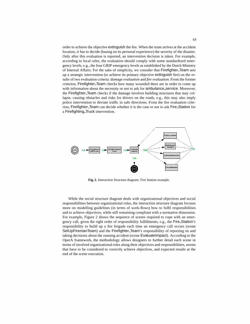
order to achieve the objectiveextinguish the fire. When the team arrives at the accidentlocation, it has to decide (basing on its personal experience) the severity of the disaster.Only after this evaluation is reported, an intervention decision is taken. For example,according to local rules, the evaluation should comply withsome standardized emer-gency levels, e.g., the four GRIP emergency levels as established by the Dutch Ministryof Internal Affairs. For the sake of simplicity, we considerthatFirefighter Team setsup a strategic intervention (to achieve its primary objective extinguish fire) on the re-sults of two evaluation criteria:damage evaluationandfire evaluation. From the formercriterion,Firefighter Team checks how many wounded there are in order to come upwith information about the necessity or not to ask forambulance service. Moreover,theFirefighter Team checks if the damage involves building structures that may col-lapse, causing obstacles and risks for drivers on the roads,e.g., this may also implypolice intervention to deviate traffic in safe directions. From the fire evaluation crite-rion, Firefighter Team can decide whether it is the case or not to askFire Station fora Firefighting Truck intervention.
Fig. 2. Interaction Structure diagram: Fire Station example.
While the social structure diagram deals with organizational objectives and socialresponsibilities between organizational roles, the interaction structure diagram focusesmore on modelling guidelines (in terms of work-flows) how to fulfil responsibilitiesand to achieve objectives, while still remaining compliantwith a normative dimension.For example, Figure 2 shows the sequence of scenes required to cope with an emer-gency call, given the right order of responsibility fulfillments, e.g., theFire Station’sresponsibility to build up a fire brigade each time an emergency call occurs (sceneSetUpFiremanTeam) and theFirefighter Team’s responsibility of reporting on andtaking decisions about the running accident (sceneEvaluateImpact). According to theOperA framework, the methodology allows designers to further detail each scene interms of involved organizational roles along their objectives and responsibilities, normsthat have to be considered to correctly achieve objectives,and expected results at theend of the scene execution.
65

Each model presented so far, i.e., social and interaction models, allows for formalannotations that complement the static semantics of previous diagrams with some dy-namic properties (see [1] for details).
3 Forms of Organizational Structure Adaptation
Principal causes of dynamic changes in the context can be described with small changesapplied to the example of the presented scenario in order to illustrate how the organiza-tion should adapt, as shown in Figure 3.
Example 1.Adaptation to stakeholder needs.Let us consider that the accident in-creases in severity. As a consequence, the domain norms (laws) necessitate a changeof responsibility. That is, as the accident involves several (autonomous) teams of fire-fighters, the city Mayor (stakeholder) decides to delegate the responsibility of callingambulance services to theFire Station because theFire Station can better coordinatethese services over different accident locations.
Real organizations are created to satisfy a specific set of stakeholders’ needs, but arealso expected to be able to adapt when changes occur within the set of needs. This con-text change could be modelled by adding a new role dependencybetweenFire Stationand First Aid Station, as depicted in Figure 3. Moreover, a new objectiveambu-lance service’ is added to this dependency which inhibits the oldambulance serviceobjective.
Example 2.Adaptation to environment conditions.Let us consider that whileFire-fighter Team is en route to the accident location (L), a huge traffic jam blocks thefastest access route. Due to the limited amount of fuel, no alternative routes are avail-able; hence, the objectiveextinguish fire is in jeopardy. The car’s onboard computerhas (autonomously) checked with theFire Station but no other cars and trucks areavailable. However, there is a helicopter available and ready for take off.
This change in the environment (symptom) could cause a failure of the objectiveextin-guish fire if no counter measures (enforcement mechanisms) have been considered inadvance. When no other alternatives are available, the enforcement has to trigger a newobjective, namely, asking for the authority to use the helicopter. This contingency canbe conditioned by two causes: the traffic jam and the fuel-tank almost empty. Figure 3shows a possible modification to adapt to the change, in this case,Firefighter Teamcollaborates with a new roleHelicopter Firefighting Team.
Example 3.Adaptation to system functionalities.Let us assume thatFire Stationhas to superviseFirefighter Team movements. Thanks to a GPS locator system,Fire Station knows whether theFirefighter Team’s achievement of the objectiveeval-uate fire respects the rule specifying that the accident evaluation must be done afterarriving at the accident location. Therefore, a faulty request from theFirefighter Teamfor having support fromFirefighting Truck can be suppressed.
66

dependency creation
& inhibition
Firefighter_Team
Fire_Station
Firefighting_Truck
Emergency_Call_Center
Police_Station
Helicopter_Firefighting_Team
First_Aid_Station
(Ex.2)
(Ex.1)
deal_with_traffic
deal_with_big_fires
ambulance_service
ambulance_service'
extinguishemergency_
location
supervising &
objective
inhibition
environment
threaten
avoid_traffic_jam
(Ex.3)
(Ex.2)
Fig. 3. Structural adaptation, according to scenarios of Example 1(Ex.1), Example 2 (Ex.2), andExample 3 (Ex.3).
The modelling of the organizational knowledge has a key rolein the whole framework,where role and objective concepts need to be properly grounded in specific system func-tionalities (e.g., agent capabilities). The software agent (or service system) that enactsthe role ofFirefighter Team has to adhere to the organizational norms, which regu-late the service invocation. These norms have been providedby the designer as a partof the organizational model. Nevertheless, the model should provide an organizationalactor with the responsibility to supervise other actor activities, namely, in Figure 3,Fire Station supervises the fulfillment of objectivedeal with big fires.
4 Towards a Formal Interpretation
Based on the formal model [2, 3], outlined in Section 2.1, we provide a set of formalingredients required to define a formal interpretation for the adaptation of organizationalstructures, as informally described in previous sections.
For the sake of simplicity, let us consider that each of the roles of thefire stationorganization (O), that is,Fire Station (fs), Firefighter Team (ft),Emergency Call Centre (ecc), Firefighting Truck (fft), Police Station (ps), andFirst Aid Station (fas), is played by a single specific (role enacting) agent. More-over, let us assume that the organization has the following (main) objectives,han-dle emergency call (hec), emergency location (el), form a brigade (fb),reach the place (rp), extinguish fire (ef ), how to react (hr), level of emergency(le), deal with big fire (dbf ), deal with traffic (dt), andambulance service (as).Therefore,O = {AO,≤O, DO, S
0O}
A = {fs, ft, ecc, fft, ps, fas}≤O= {fs ≤O ecc, fs ≤O ft, ft ≤O fft, ft ≤O ps, ft ≤O fas}.
67

The setsO, AO, and≤O provide a formal interpretation of the semantics depictedin the dependency diagram of Figure 1. For example, the partial order set≤O definesall the dependencies provided in the diagram between agents(in AO) involved in theorganization (O).
We introduce the setDO that represents the formalization of the objectives of theorganization and agents. For the sake of simplicity, we adopt the logical connectives ofand (∧) andor (∨) respectively to model sub-objectives inor andand decomposition,in order to define alternative ways for an objective achievement. The formalization ofDO is the followingDO = {hec} = {(el ∧ fb ∧ ef)}. That is, in order to handlean emergency call (hec) the accident location has to be established (el), a fire brigadehas to be formed (fb) and then the fire has to be estinguished (ef ). Notice that, theobjectiveextinguish (ef ) the fire is composed of other sub-objectives as follows:ef =(rp ∧ le ∧ hr), namely, in that case, the fire brigate has toreach the place, establishthe accident severity (le) and then decide how to react (hr). Worth noticing that asthe objectivehow to react (hr) may be achieved in several ways (say alternatives), asimple formal representation is:hr = (dbf ∨ dt ∨ as ∨ (dbf ∧ as) ∨ ...)
The initial setS0O characterizes the agent specialization and the way to achieve a
specific state of affair. In this case, we considered that agents have to acquire the capa-bility for achieving some objectives before acting. To thisend, we subdivideS0
O in twosub-setsS1 andS2 indicating two different instants for getting the right organizationalcompetencies/expertise.S0
O is the initial set of organization’s assets:S0
O = (S1 ∪ S2), where:S1 = {Cfshec, Ceccel, Cfsfb, Cftrp, Cftef, Cfthr, Cftle, Cfftdbf, Cpsdt, Cfasas}S2 = {Rfshec, Eeccel, Efsfb,Hftrp,Rftle,HfsRfthr,Hfftdbf,Hpsdt,Hfasas}
Now, the above formal interpretation adheres to the intended meaning given bythe conceptual models defined by theSocial Dependencydiagram of Figure 1 and themodel annotations provided for each scene. In order to extend our formal interpreta-tion with the information defined by theInteraction Structurediagram of Figure 2,we need to figure out possible strategies to realize the organizational objectivehan-dle emergency call (hec), as follows4.s1: Rfshec ∧ (Eeccel→ Efsfb→ (Hftrp→ (Rftle ∧RftHfftdbf)))s2: Rfshec ∧ (Eeccel→ (Efsfb ∧RfsHftrp) →
(Hftrp→ (Rftle→ (RftHfftdbf ∧RftHfasas))))...: ...
For example, adoptings1, as the agentfs that enacts the roleFire Station is re-sponsible for dealing with the main organizational objective handle emergency call(hec), it configures the organizational roles (agents) as indicated in Figure 2. That is, theagentEmergency Call Centre (ecc) has to informFire Station of the accident loca-tion (el); hence, the agentfs canform a brigade of firefighters. In Figure 2, these two
4 As organizational strategies are sequences of temporal logic formulas that model agenttasks to achieve (sub)objectives, we simply use logical connectives ofand (∧), or (∨) andimplication (→) to give the correct order of execution.
68

objectives are respectively described within the two scenes: EmergencyCallOccursandSetupFiremanTeam. Turning to the strategys1, once the brigade has been formed(Efsfb), Firefighter Team attempts toreach the place of the accident (Hftrp) be-fore assuming the responsibility to report on the emergencylevel (Rftle) and to takeany decisions aboutFirefighting Truck intervention (RftHfftdbf ). Again, in Figure 2,the latter two achievements have been defined within the scenesEvaluateImpact andTruckNeeded respectively.
It is worth noticing that the provided formal model reflects the main idea of theOperA methodology about the desire to preserve a good trade-off between the organi-zational specification and the service system flexibility. In other words, despite agentshaving to adhere to the organizational specification, theseagents still have enough au-tonomy to achieve organizational objectives in convenientways. In fact, the formalspecification reflects the same aim, namely, an organizational structure may bring aboutdifferent strategies (e.g.,s1 ands2), while guaranteeing the achievement of the sameset of objectives. According to each of the causes of contextchange described by theexamples in the previous sections, we provide a formal interpretation of the requiredadaptation process that should be followed by the organization.
Adaptation by re-considering the needs. This is the case where an existing respon-sibility should change, as illustrated by Figure 3. The steps that are required for theorganization to adapt its structure are the following:
– Rfsstruct−(O, ft ≤O fas), eliminate the old dependency;
– Rfsstruct+(O, fs ≤O fas), add the new dependency;
– Rfsstrateg−(O, hr): the hr objective is removed from the strategy to allow a
change to the objective (see below). This change is needed asas is no longer underthe responsibility ofFirefighter Team but under the responsibility ofFire Station;
– Rfsstrateg+(O, d), whered = (hr
′∧as) andhr′= (dbf∨dt∨(dbf ∧dt)). Also,
HfsRfthr is replaced byHfsRfthr′to encompass for the change of responsibility
for calling the ambulance service.
The previous strategies (s1 ands2) must now include the above changes. For exam-ple, the second strategy (s2) has all the ingredients, but we need two modifications toreach a suitable target (s′2). The first is the state:Rftle⇒ RfsHftle to emphasize thatwhen the emergency level scales up,Fire Station has the responsibility to control thereported emergency level in order to correctly regulate thepermission to ask for helpto other organizational roles. The second is:RftHfasas ⇒ RfsHfasas, namely, thecontext change implies a responsibility change as well. Thus, a suitable strategy builtons2 is:s′2: Rfshec ∧ (Eeccel→ (Efsfb ∧RfsHftrp) →
(Hftrp→ (Rftle→ (RftHfftdbf ∧RfsHfasas))))
Adaptation by sensing the environment. This is the case where symptoms —relatedto environmental changes— may conduct to potential servicesystem failures. Hence,the symptoms have been modelled along with specific countermeasures, which implychanges in the initial organizational structure, as illustrated in Figure 3. Formally, thesteps required for the organization to adapt its structure are the following:
69

– Rfsstaff+(O, hft), add a new agent able to enact the role
Helicopter Firefighter Team (hft), this also introduces the responsibility for theFire Station to make a helicopter available, e.g., during emergency conditions;
– Rfsstruct+(O, ft ≤O hft), this defines the possibility for theFirefighter Team
to call onHelicopter Firefighter Team (but only during emergency conditions).– Rftstrateg
+(O, atj), whereatj is the objectiveavoid traffic jam, andatj =((symptom1 ∧ symptom2) → ah). This formalizes the presence of emergencyconditions, namely, the possibility for the agentft to ask agenthft for help (ah -ask for help) but only if the two environment symptoms occur.
In this context change, an appropriate strategy for achieving the organizational ob-jectives might be built on the basis ofs1 as follows. AsFirefighter Team cannot reachthe accident place (rp) and establish the level of emergency (le), it has to delegatethese responsibilities:Hftrp ⇒ HftRhftrp andRftle ⇒ RftHhftle. Therefore,s′1:Rfshec ∧ (Eeccel→ Efsfb→ (HftRhftrp→ (RftHhftle ∧RftHfftdbf)))
Adaptation by supervising system services invocation. This is the case where the ser-vice system level should take into account policies specified at the organizational level.Fire Station agent should be able to supervise the agentFirefighter Team, in particu-lar when it invokes the service that brings about the objectivedeal with big fire (dbf )achievement. In fact, this may be the cause of failure at the service level, e.g., due to awrong pre-condition in service invocation. Therefore, within our formal specification,we need to define the agent’s ability to supervise specific activities of others agents, asfollows.
Definition 5 (Supervising Ability). Given an organizationO = {AO,≤O, DO, SO}and two agentsa, b ∈ AO, the supervising ability of an agenta in respect to anotheragentb to realizeϕ is defined as:SA(a,b)ϕ ≡ RaHbϕ→ ♦((Hbϕ∧◦¬ϕ) → Raϕ).
This means that agentb attempts to realizeϕ with a certain degree of uncertaintywhile under the responsibility ofa. However, agenta is directly responsible for theachievement ofϕ every timeb fails to realizeϕ. Notice that, contrary to others contextchanges where the change depends on a variable that model some domain entities, here,the change depends on how the activity of another agent is fulfilled. Turning to ourexample, to effectively deal with the context change, we need a modification within theinitial stateS2, adding the new state:SA(fs,ft)ef , whereef = (rp ∧ le ∧ hr) is the previous objectiveextinguish fire.
This modification guaranteesFire Station (fs) to be informed every timeFire-fighter Team (ft) tries to deal withle or hr before achievingreach the place (rp).Notice that, as given by Definition 5,Fire Station becomes directly responsible ofefin the caseFirefighter Team does not succeed withef . Hence, due to the definitionof responsibility given in Section 2.1,fs can attempt itself to deal withef or can at-tempt to makeft responsible ofef . In the latter case,ft can attempt to realizeefagain. Moreover, another modification affects the initial stateS2, namely, after adding
70

SA(fs,ft)ef the stateHftrp becomes redundant. Therefore, considering the old strat-egys1, we create a new strategys′′1 as follows:s′′1 : Rfshec ∧ (Eeccel→ Efsfb→ (SA(fs,ft)ef → (Rftle ∧RftHfftdbf)))
5 Related Work
In [15], a formal model, A-LTL, for describing adaptive programs in response to adap-tation requests. A-LTL is an extension of the well known LTL logic. Their approachseems very suitable (at requirements level) to describe theexpected program behaviorof an adaptive program (e.g., a software agent) in order to enable for checking consis-tency in temporal logic specification. We share their idea that the use of temporal logicis a good way to allow for model checking or other formal verification in the contextof adaptive systems. However, [15] considers (adaptive) programs as state machines,characterizing the adaptation as a program behavior changeduring its execution. Ourwork allows a more fine-grained requirements specification for agents involved in anorganization. That is, we formalize adaptation (by the use of CTL temporal logic) aschanges in the organization structures in terms of modifications between agent relation-ships and responsibilities, as it actually happens in humanorganizations.
There exist many different agent-oriented software engineering methodologies [7].Only a few of them (e.g., see [14, 11]) have emphasized the importance of organiza-tional and social abstractions to shape and drive the systemarchitectural and functionalrequirements. In [11, 9], the Tropos methodology has been enriched to effectively dealwith the development of adaptive systems, allowing designers to endow agents withadaptation abilities/features without focusing on agentssocieties. Our proposed frame-work thus complements the Tropos extension very nicely.
In [6] a good survey about self-organizing mechanisms inspired by social behav-iors have been described. The authors refer to several kindsof self-organizing behav-iors, which come from studies of insects and human societiesas well as business andeconomic organizations, as an important source of inspiration for the development ofadaptive systems. In the same line as the OperA methodology,the authors claim theneed of socially inspired computing metaphors as a new paradigm for adaptive systemsdevelopment.
6 Conclusions and Future Work
In this paper, we have studied forms of organizational adaptation to cope with differ-ent types of context change. The contribution of this paper is twofold: on one side, westudied and described adaptation within organizational structures by exploiting the Op-erettA design tool to produce the related diagrams. On the other side, we provided awell defined formal model based on the CTL temporal logic to characterize the adap-tation process also from a dynamic dimension. Moreover, thepaper shows that thesetwo forms of requirements specification complement one another. Worth noticing, theformal specification gives the possibility to model different degrees of uncertainty re-garding the way an agent has for achieving an objective (state of affair); hence, thisspecification better reflects the behavior of (human) organizational roles that an agent
71

from time to time may enact. The ideas of this paper have been illustrated by examples,within a simplified crisis management scenario suitable to emphasize design issues oforganizations that operate in a real dynamic complex environment.
As future work, we will extend the OperA design methodology to allow designersto evaluate different organizational structures with respect to context changes. More-over, the CTL formal specification allows us to envisage forms of analysis of formalproperties (e.g., model checking).
References
1. V. Dignum. A Model for Organizational Interaction: based on Agents, founded in Logic.PhD thesis, Universiteit Utrecht, 2004.
2. V. Dignum and F. Dignum. A logic for agent organization. InFormal Approaches to Multi-Agent Systems (FAMAS@Agents’007). Durham, 2007.
3. V. Dignum and C. Tick. Agent-based Analysis of Organizations: Performance and Adap-tation. In IEEE/WIC/ACM Int. Conf. on Intelligent Agent Technology (IAT-07), California,USA, 2007. IEEE CS Press.
4. E. Emerson. Temporal and modal logic. In J. van Leeuwen, editor, Handbook of TheoreticalComputer Science, volume B, pages 955–1072. MIT Press, 1990.
5. A. G. Ganek and T. A. Corbi. The dawning of the autonomic computing era.IBM SystemsJournal, 42(1):5–18, 2003.
6. S. Hassas, G. D. Marzo-Serugendo, A. Karageorgos, and C. Castelfranchi. Self-organisingmechanisms from social and business/economics approaches. Informatica, 30(1):63–71,2006.
7. B. Henderson-Sellers and P. Giorgini, editors.Agent-Oriented Methodologies. Idea GroupInc., 2005.
8. J. O. Kephart and D. M. Chess. The vision of autonomic computing. Computer, IEEEComputer Society Press, 36(1):41–50, 2003.
9. M. Morandini, L. Penserini, and A. Perini. Operational Semantics of Goal Models in Adap-tive Agents. InProceedings of the eighth international joint conference on Autonomousagents and multiagent systems (AAMAS-09). ACM, 2009.
10. D. M. Okouya and V. Dignum. A prototype tool for the design, analysis and development ofmulti-agent organizations. InDEMO Session: Proc. of the 7th Int. Joint Conf. on AutonomousAgents and Multiagent Systems (AAMAS-08). ACM, 2008.
11. L. Penserini, A. Perini, A. Susi, and J. Mylopoulos. HighVariability Design for Soft-ware Agents: Extending Tropos.ACM Transactions on Autonomous and Adaptive Systems(TAAS), 2(4), 2007.
12. I. Porn. Some basic concepts of action. InS. Stenlund (Ed.), Logical Theory and SemanticalAnalysis, Reidel, 1974.
13. Y. So and E. H. Durfee. Designing organizations for computational agents.Simulatingorganizations: computational models of institutions and groups, MIT Press, pages 47–64,1998.
14. F. Zambonelli, N. R. Jennings, and M. Wooldridge. Developing multiagent systems: The gaiamethodology. ACM Transactions on software Engineering and Methodology, 12(3):317–370, 2003.
15. J. Zhang and B. H. Cheng. Using Temporal Logic to Specify Adaptive Program Semantics.Journal of Systems and Software (JSS), 79(10):1361–1369, 2006.
72

Automatic Generation of executable Behavior: AProtocol-driven Approach
Christian Hahn1, Ingo Zinnikus1, Stefan Warwas1, Klaus Fischer1
DFKI GmbHStuhlsatzenhausweg 3
66123 Saarbrucken{Christian.Hahn,Ingo.Zinnikus, Stefan.Warwas, Klaus.Fischer}@dfki.de
Abstract. Modern information systems are considered as collection ofindependent units that interact with each other through the exchangeof messages. Especially in the context of multiagent systems, the in-teraction between agents is of particular importance. Agent interactionprotocols (AIPs) are one important mechanism to define agent-basedinteractions. AIPs play a major role within the platform independentmodeling language for multiagent systems (Dsml4mas). In this paper,we demonstrate how to design protocols with Dsml4mas and discuss amodel-driven approach to use the protocol description to generate exe-cutable code.
1 Introduction
Multiagent systems (MASs) define a powerful distributed computing model, en-abling agents to cooperate with each other. Thus, beside, aspects like agentsand organizational relationships, the interaction between agents is considered asbasic building block of MASs (see [1]). In accordance to [2], an interaction can beviewed as a formalization of a concept of dependence between agents, no matteron whom or how they are dependent. An agent interaction protocol (AIP) as aspecial case of interactions describes the manner how messages are exchanged.
The importance of interactions in MAS is underlined by the fact that ex-isting methods for designing MAS like Tropos [3], Prometheus [4], Gaia [5], orINGENIAS [6] already included mechanisms to express AIPs. In particular, allof them use some sort of Agent UML diagrams (AUML) [7] for defining agent-based interactions. However, AUML in its current version has some drawbacksthat are intended to be resolved by our approach.
Hence, in this paper, we demonstrate how to design protocol-based interac-tions using a platform independent modeling language for the domain of MASscalled Dsml4mas. In [8] an overview of Dsml4mas and a model transforma-tion to the execution platform of Jack Intelligent Agents1 is given. The modeltransformation to Jack allows to close the gap between design and implementa-tion by taking the complete design made with Dsml4mas and transferring it tocorresponding concepts of Jack.1 http://www.aosgrp.com/index.html
73

However, especially in a more business-oriented context, partners often firstdefine the manner in which they interact followed by defining the behaviors thatactual implement the agreed interactions. Hence, in this paper, we discuss aslightly different approach which is more methodology-like. Instead of checkingwhether the agent’s internal behavior implements the protocol description, wefocus on a protocol-driven approach that take a protocol description as a baseand generates a corresponding behavior description that automatically conformsto the agreed AIP. In a second step, the system designer refines the behaviordescription by adding for instance private and critical information. Finally, in alast step, the generated behavior in combinations with the remaining design (i.e.agents, organizations, roles, etc.) is transformed to Jack code that in combinationwith manually written code (if necessary) can be executed.
The remainder of this paper is organized as follows. Section 2 discusses theinteraction and behavior aspect of Dsml4mas in detail. Followed by Section3, demonstrating how to design AIPs with Dsml4mas. Section 4 discusses ourprotocol-driven approach by illustrating how to transform AIPs to executablecode. Related work is given in Section 5. Finally, a conclusion is drawn.
2 Domain Specific Modeling Language for MultiagentSystems
The domain specific platform independent modeling language for MASs(Dsml4mas) defines a graphical language that allows defining MASs indepen-dent of any existing agent-oriented programming language (AOPL). However,model transformations can be applied to automatically generate code in accor-dance to the AOPLs Jack and Jade. The abstract syntax of Dsml4mas is definedby a metamodel called PIM4Agents that consists of several aspects (e.g. agent,organization, environment, role, interactions, behaviors, etc.) each focusing onparticular core building blocks of MASs. The PIM4Agents bases on Ecore themeta-metamodel of the Eclipse Modeling Framework2. In this section, we lay thefoundations for the remaining parts of this paper and discuss the interaction andbehavior aspects in detail but also mention the links to the remaining aspects.
2.1 Interaction Aspect
The partial metamodel of a Protocol in Dsml4mas is depicted in Fig. 1. AProtocol is considered as a special form of an Interaction. Accordingly, the mainconcepts of a Protocol are Actor, ACLMessage, MessageFlow, MessageScope andTimeOut. In the deployment view, furthermore, the system designer can specifyhow Protocols are used within Organizations. This is done through the concept ofan InteractionUse that defines which organizational members (which are of thetype AgentInstance) are bound to which kind of Actor as part of an ActorBinding.Beside a static binding, the designer may want to bind the AgentInstances atrun-time, which can be done within a Plan using the AssignRole concept.2 http://www.eclipse.org/modeling/emf/
74
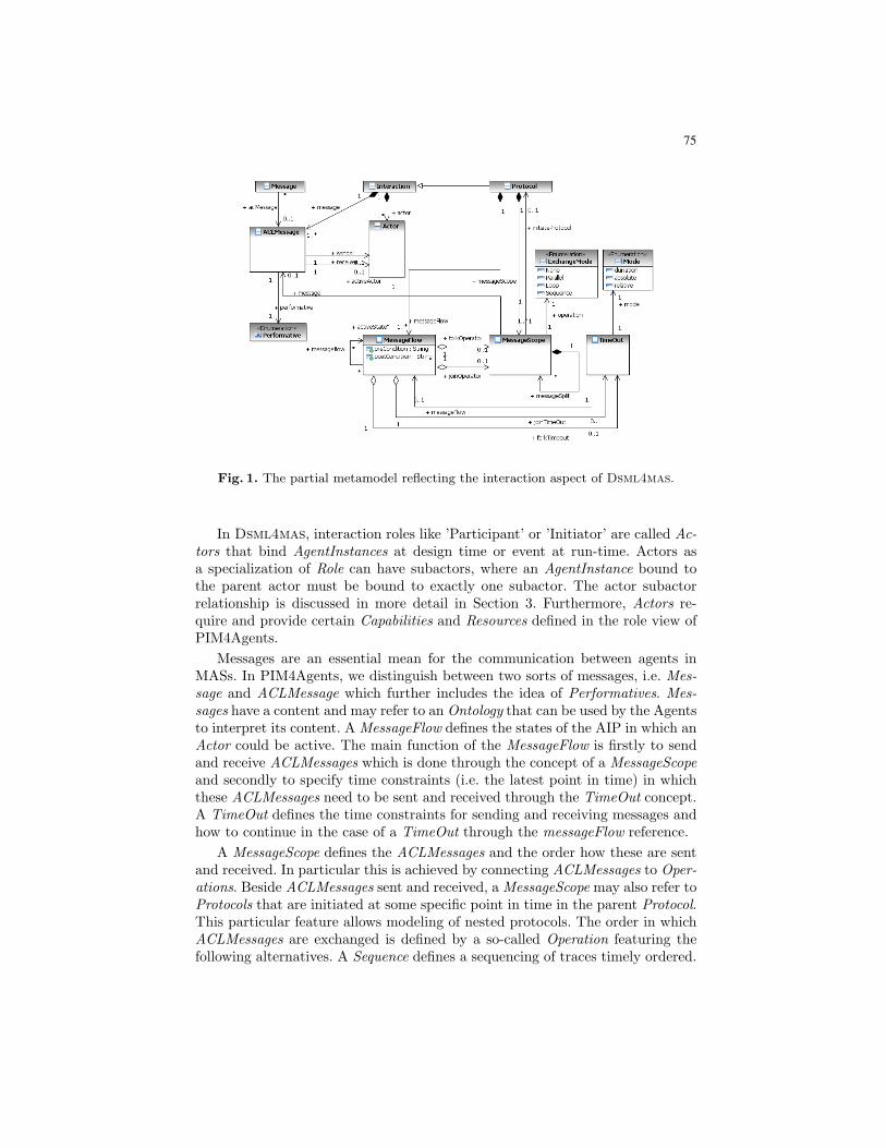
Fig. 1. The partial metamodel reflecting the interaction aspect of Dsml4mas.
In Dsml4mas, interaction roles like ’Participant’ or ’Initiator’ are called Ac-tors that bind AgentInstances at design time or event at run-time. Actors asa specialization of Role can have subactors, where an AgentInstance bound tothe parent actor must be bound to exactly one subactor. The actor subactorrelationship is discussed in more detail in Section 3. Furthermore, Actors re-quire and provide certain Capabilities and Resources defined in the role view ofPIM4Agents.
Messages are an essential mean for the communication between agents inMASs. In PIM4Agents, we distinguish between two sorts of messages, i.e. Mes-sage and ACLMessage which further includes the idea of Performatives. Mes-sages have a content and may refer to an Ontology that can be used by the Agentsto interpret its content. A MessageFlow defines the states of the AIP in which anActor could be active. The main function of the MessageFlow is firstly to sendand receive ACLMessages which is done through the concept of a MessageScopeand secondly to specify time constraints (i.e. the latest point in time) in whichthese ACLMessages need to be sent and received through the TimeOut concept.A TimeOut defines the time constraints for sending and receiving messages andhow to continue in the case of a TimeOut through the messageFlow reference.
A MessageScope defines the ACLMessages and the order how these are sentand received. In particular this is achieved by connecting ACLMessages to Oper-ations. Beside ACLMessages sent and received, a MessageScope may also refer toProtocols that are initiated at some specific point in time in the parent Protocol.This particular feature allows modeling of nested protocols. The order in whichACLMessages are exchanged is defined by a so-called Operation featuring thefollowing alternatives. A Sequence defines a sequencing of traces timely ordered.
75

Fig. 2. The partial metamodel reflecting the core behavioral aspects of Dsml4mas.
A Parallel denotes that several traces are executed concurrently and a Loop de-scribes that a particular trace is executed as long as a particular Condition issatisfied. Finally, the None operation specifies that only a single ACLMessage isexchanged.
A combination of these Operations can easily be achieved by the Mes-sageScope’s messageSplit reference which allows to nest Operations. Furtherbranching can be defined by specifying transitions between MessageFlows usingtheir messageflow reference. A preCondition and postCondition can be specifiedin order to define in which case the transition is triggered.
2.2 Behavioral Aspect
The behavioral aspect describes how plans are composed by complex controlstructures and simple atomic tasks and how information flows between thoseconstructs. The core concepts of the behavioral aspect are depicted in Fig. 2.
A Plan can be considered as a specialization of the abstract Behavior tospecify an agent’s internal processes. An Agent can use several Plans whichcontain a set of Activities and Flows (i.e. ControlFlow, InformationFlow) thatlink Activities to each other. Furthermore, a Plan refers to a set of MessageFlowsto ensure that the message exchange (defined by the Protocol) is implementedby the particular Plan in an adequate manner.
The body of a Plan is mainly represented by the specializations of an Activity.A StructuredActivity is an abstract class that introduces more complex controlstructures into the behavioral view. It inherits from Activity, but additionallyowns a set of Activities and Flows.
A Sequence as a specialization of a StructuredActivity denotes a list of Activi-ties to be executed in a sequential manner as defined by contained ControlFlows
76

through their sink and source attributes. Beside using the concept of Sequence,a sequence of Activities can additionally be directly described by linking theparticular Activities through ControlFlows. However, the concept of Sequenceallows hiding the concrete trace which might be important when designing com-plex Plans as scalability is improved. A Split is an abstract class that definesa point in a Plan where a single thread of control splits into multiple threadsof control. We distinguish between Parallel and Decision as specializations. AParallel is a point in a Plan, where a single thread of control splits into multiplethreads of control which are executed in parallel. Thus a Parallel allows Activi-ties to be executed simultaneously or in any order. How the different threads aresynchronized is defined by a SynchronizationMode. Feasible options are XOR,AND and NofM (i.e. n of m paths are synchronized).
In contrast to a Parallel, a Decision in PIM4Agents is a point in a Planwhere, based on a Condition, at least one Activity of a number of branchingActivities must be chosen. A Decision can either be executed in an XOR orOR manner. In contrast, a Loop is a point in a Plan where a set of Activitiesare executed repeatedly until a certain pre-defined Condition evaluates to false.Is allows looping that is block structured, i.e. patterns allow exactly one entryand exit point. A ParallelLoop as a specialization of Loop and Parallel allowsspecifying iterations in the form that each trace is executed in parallel.
Like a StructuredActivity, a Task is an abstract class that inherits from Activ-ity. Unlike a StructuredActivity, a Task mainly focuses on atomic activities andthus does not contain any Activities or Flows. Sending and receiving messagesis covered by the Send and Receive tasks. Furthermore, the AssignRole activ-ity allows to assign AgentInstances to Roles (i.e. Actors and Wait to wait for aparticular time or event. Finally, an InternalTask can be used to define code.
3 Example: Contract Net Protocol
In the following, we demonstrate how to model AIPs using Dsml4mas’s graph-ical editor. This editor is based on the abstract syntax (i.e. PIM4Agents meta-model) partly introduced in the previous section and uses the Eclipse’s GraphicalModeling Framework3. Beside the graphical notation that supports modeling ofeach aspects in a graphical manner, by clicking on the graphical symbol, theproperties of this concept can be further specified and refined in the propertiesview. A detailed overview on the graphical editor can be found in [9].
For illustrating how to model AIPS, we use the Contract Net Protocol (CNP)[10] which is depicted in Fig. 3. Therefore, we firstly introduce two actors calledInitiator and Participant. The protocols starts with the first message flow ofthe Initiator that is responsible for sending the CallForProposal message of theperformative type cfp. The CallForProposal message specifies the task as well asthe conditions that can be specified within the properties view of the graphicaleditor. When receiving the CallForProposal, each agent instance performing the
3 http://www.eclipse.org/gmf/
77

Fig. 3. Contract Net Protocol modeled using Dsml4mas.
Participant decides on the base of free resources whether to Propose or Refuse.However, how this selection function is defined cannot be expressed in the proto-col description, as private information are later manually added to the automat-ically generated behavior description. To distinguish between the alternatives,two additional actors (i.e. Propose and Refuse) are defined that are subactorsof the Participant (i.e. any agent instance performing the Participant shouldeither perform the Propose or Refuse actor). The transitions between the mes-sage flow within the Participant and the message flows of the Refuse or Proposeactors through the messageFlow reference underline the change of state for theagent instance performing the Participant actor. However, the transitions areonly triggered if a certain criterion is met. In the CNP case, the criterion is thatthe Initiator got all replies, independent of its type (i.e. Refuse or Propose). ThepostConditions of a MessageFlow can be defined in the properties view of thegraphical editor. The message flows within the Refuse and Propose actors arethen responsible for sending the particular messages (i.e. Refuse and Propose).
After the deadline expired—defined by the TimeOut—or all answers sent bythe agent instances performing the Participant actor are received, the Initiatorevaluates the proposals in accordance to a certain selection function, choosesthe best bid(s) and finally assigns the actors BestBidder and RemainingBidderaccordingly. Again, the selection function is not part of the protocol, but canbe defined later on in the corresponding plan. Both, the BestBidder actor aswell as the RemainingBiddder actor—containing the agent instances that werenot selected—are again subactors of the Propose actor. The Initiator sends anAcceptProposal message to the BestBidder and a RejectProposal message to theRemainingBidder in parallel.
After completing the work on the assigned task, the BestBidder reports itsstatus to the Initiator by either sending an InformResult, InformResult or Failuremessage. Again, for this purpose, we distinguish again between InformResult,InformDone and Failure actors which are subactors of BestBidder.
78

Fig. 4. Conceptual model transformations between (i) the interaction aspect and be-havioral aspect (left hand side) and (ii) the behavioral aspect and JACKMM planaspect (right hand side).
4 Model-driven Methodology to Generate ExecutableCode
The process of generating executable code based on a protocol description isdiscussed in this section in more detail. This methodology consists of two phasesdepicted in Fig. 4. In a first step, a transformation from the protocol descriptionto the internal behaviors of the participating agents is discussed. In a second step,the transformation from the behavioral perspective to the agent-based executionplatform Jack is given. Both transformations were implemented utilizing theAtlas Transformation Language4.
4.1 From Interaction Protocol to Behaviors
The first step of the interaction to behavior transformation (depicted on the lefthand side of Fig. 4) is to generate a Plan for the set of MessageFlows an Actoris active within a Protocol. Each Plan generated by this mapping rule is thenincluded in a Capability which is provided by the particular Actor and used bythe AgentInstances bound to that Actor.
Within a Plan, the order of sending and receiving Messages is deduced fromthe order in which the MessageFlows and the corresponding MessageScopes arearranged and to which Operations (i.e. None, Parallel, Loop or Sequence) theMessageScopes refer. In particular this means that a Parallel operation is mappedto a Parallel activity, a Loop operation is mapped to a Loop activity, etc. As aNone operation only refers to one Message, it is either mapped to a Receiveor Send task, depending on whether the corresponding MessageFlow sends or4 http://www.eclipse.org/m2m/atl/
79

Fig. 5. The generated SendAcceptReject plan.
receives a message. The Send or Receive activity than refers to that ACLMessage.As ACLMessages in the Protocol can be sent and received to/from multipleActors that again contain multiple agent types, both, Send and Receive, haveto be included in a parallel statement (i.e. ParallelLoop) that iterates over allentities. This allows to keep a Plan as generic as possible, as the informationhow many agent instances are finally playing the particular Actors needs notbe known at design time. Moreover, we introduce a Decision activity for eachMessageFlow that refers to MessageFlows through the messageFlow reference.
Finally, a TimeOut is mapped in the manner that a Wait activity is intro-duced and integrated into a Parallel activity consisting of two paths. One pathincludes the Wait activity, the other one includes the Activities responsible forsending and receiving messages.
Fig. 5 depicts the generated initiator’s plan for collecting the initial responsesfrom the participant’s side and sending of accept and reject messages. It baseson the message flows responsible for receiving the Refuse and Propose messagesand sending the Reject and Accept messages. The plan mainly consists of threephases. In the first phase, the CollectResponses parallel is triggered that has twopaths, one responsible for waiting until the particular TimeOut is raised and theone for collecting the responses. The execution mode of this parallel statementis XOR, meaning that the statement can be left after all messages were receivedor a certain time—which is defined by the TimeOut in the Protocol—has beenwaited. The execution mode of a parallel statement can be selected within theproperties view of the graphical editor. This is also the case for Messages referredto by Send/Receive and TimeOuts referred to by Wait.
The messages are collected inside a Parallel called CollectResponsesParallel.For each entity bound to the Participant actor, either the ParallelLoop Receive-ProposeParallelLoop or the ParallelLoop ReceiveRefuseParallelLoop is executed.
In the second phase, the SelectBestBidder plan is triggered which needs to beadded manually as the information according to which criteria the best biddersare selected is not part of the protocol description. After an allocation has beenevaluated, in the last phase, the agent instances are assigned to the corresponding
80

Fig. 6. The generated SendAcceptReject team plan in Jack (partial).
actors BestBidder and RemainingBidder and informed accordingly. This is donein the SendAcceptReject parallel, where the Reject and Accept messages are sentto the RemainingBidder and BestBidder concurrently. Again, the send tasks areintegrated into a parallel loop activity specifying that for each agent instancebound to one of the actors either the message Accept or Reject is sent.
4.2 From Behaviors to Jack
Jack is a process-centric agent-based programming language that bases on princi-ples of the belief-desire-intention theory [11]. Jack mainly focuses on the internalperspective of an agent defined by so-called plans, an interaction protocol per-spective between agents is not provided. In [12], we defined a metamodel forJack called JACKMM that distinguishes between the team view and the processview. The right hand side of Fig. 4 depicts some concepts of the process viewbriefly discussed in the following. A TeamPlan in JACKMM is a special Planthat can be used within a Team to organize its members. Normally, a Team-Plan handles exactly one and may send several Events which are pretty similarto Messages in Dsml4mas (at least those Events that are of the type messageevent). Several activities like on the one hand SendNode, ParallelNode, Deci-sionNode and Flows on the other hand to connect these activities are availablewithin a TeamPlan to define how to achieve a certain goal. A more completeoverview on JACKMM-related concepts can be found in [12].
The conceptual transformation from the behavioral metamodel of Dsml4masto the Jack process metamodel is illustrated on the right hand side of Fig. 4.
81

For each Plan generated by applying the interaction to behavior transforma-tion, a TeamPlan is generated. The body of this TeamPlan is generated in anone-to-one manner at least for those activities in PIM4Agents that were directlysupported by Jack. An example is the Send activity which is transformed toa SendNode in Jack. The Message a Send refers to is directly transformed tothe corresponding Event. As a TeamPlan automatically handles an Event, wedo not need to directly transfer Receive activities of Dsml4mas to related con-cepts in Jack. However, as Plans in Dsml4mas base on MessageFlows whichclearly describe which Messages are received and sent, we can easily generatethe TeamPlan-specific structure. Concepts like Parallel, Decision and Wait canalso be mapped in an one-to-one fashion as illustrated in Fig. 4. In the con-trast to concepts like Loop, ParallelLoop and Sequence which are not directlysupported by Jack. In the case of Sequences this can easily be compensated byconnecting the predecessor of a Sequence with the first activity within the Se-quence and the last activity of a Sequence with its successor. For the conceptsof Loop and ParallelLoop, we define templates consisting of several activities ofthe process view (e.g. Decision concept used for looping purpose) and filled withthe activities contained by the source concepts (i.e. Parallel and ParallelLoop).
Fig. 6 depicts the generated SendAcceptReject team plan. Due to space re-strictions, we mainly focus on the part responsible for sending the Accept event.Though, except the names of the variables and the event sent, the part of sendingthe Reject event is rather similar. As depicted in Fig. 4 and mentioned earlier,for each Plan is Dsml4mas, we generate a corresponding TeamPlan. Hence,the corresponding team plans ReceivePropose and ReceiveRefuse are not partof SendAcceptReject. Those are automatically triggered whenever a Refuse andPropose event is sent by the any participant. Both plans are responsible for up-dating the belief set of the particular agent with the information whether thereplying agent instance refuses or proses.
After the deadline expires or all answers were received, the SelectBestBidderteam plan is invoked using the concept achieve. Internally, the achieve statementposts an internal event which triggers the SelectBestBidder plan and waits untilthe best bidder and remaining bidders were selected. Afterwards, the evaluationis reported to the proposed agent instances. Like in the corresponding planof Dsml4mas illustrated in Fig. 5, this is done using the parallel statement ofJack. For each, the best bidders and the remaining bidders, a path is instantiatedresponsible for sending the particular event. The process of sending is again donein a parallel statement. However, in this case, the parallel works as a paralleliteration, as for each agent instance of the best bidders (i.e. accept) an eventmes is sent. The loop terminates if every instance is addressed which is ensuredby the code BestBidderEnumeraion.hasMoreElements() part of the decision.
5 Related Work
In the MAS community, Agent UML (AUML) is the most prominent modelinglanguage for specifying AIPs. AUML is an extension of the Unified Modeling
82

Language (UML) to overcome the limitations of UML with respect to MASdevelopment. In particular, AUML specifies AIPs by providing mechanisms todefine agent roles, agent lifelines (interaction threads, which can split into severallifelines and merge at some subsequent points using connectors like AND, ORor XOR), nested and interleaved protocols (patterns of interaction that can bereused with guards and constraints), and extended semantics for UML messages(for instance, to indicate the associated communicative act, and whether mes-sages are synchronous or not). However, AUML does not allow to express morespecialized subactors. For this purpose, in [13], Haugen suggested two improve-ments to the UML 2.0 sequence diagram notation in order to define multicastmessages and combined-fragment iterators over subsets. This approach shareseveral commonalities with our approach. However, the suggested improvementsare not part of the recent version of AUML. Even if AUML can be consideredas de facto standard for modeling AIPs, tool supported is very limited. In [14],a textual notation and graphical tool have been presented. In [15], an approachis presented that automatically interprets AUML AIPs. However, the resultingtool called Paul (Plug-in for Agent UML Linking) only supports parts of AUMLas only the alternative operator is implemented. Furthermore, the code genera-tion is limited to two agent lifeline and it is pretty unclear if multicast messagesare supported.
6 Conclusion
This paper discusses an approach to describe agent interactions in a protocol-based manner. For this purpose, we discussed the interaction and behavioralparts of our domain specific modeling language for MAS (Dsml4mas) and illus-trated how to use Dsml4mas to design the Contract Net Protocol. The approachwe are taking in the interaction aspect is intended to express that there are differ-ent actors relative to the initiator described in the protocol. Rather than definingone actor that is fully general, we now describe one actor for each distinct sit-uation. Hence, protocols like the Contract Net Protocol can easily be describedusing the interaction aspect of Dsml4mas as one-to-many interactions as well asthe differentiation between subactors of the same actor is naturally supported.This is a very interesting result as AUML lacks this kind of expressiveness.
Beside demonstrating how to model AIPs using Dsml4mas we furthermorediscussed how to transform agent interaction protocols designed to executablebehaviors by applying principles of model-driven development. Therefore, wefirstly transformed the interaction description to a process-centric model inDsml4mas. Therefore, we defined a mapping between concepts of the inter-action and the behavioral metamodel. This was mainly done in an one-to-onemanner, however, private information needs to be integrated in the agents’ in-ternal behavior to make each agent’s behavior complete regarding execution. Ina next and last step, the Dsml4mas model including the generated behavioralmodel is mapped to the agent-based programming language Jack which finallyallows to execute the protocol description.
83

References
1. Jennings, N.R.: An agent-based approach for building complex software systems.Communications of the ACM 44(4) (2001) 35–41
2. Malone, T., Crowston, K.: The interdisciplinary study of coordination. ACMComputing Surveys 26(1) (1994) 87–119
3. Susi, A., Perini, A., Giorgini, P., Mylopoulos, J.: The tropos metamodel and itsuse. Informatica 29(4) (2005) 401–408
4. Padgham, L., Thangarajah, J., Winikoff, M.: AUML protocols and code generationin the prometheus design tool. In: AAMAS ’07: Proceedings of the 6th internationaljoint conference on Autonomous agents and multiagent systems, New York, ACM(2007) 1–2
5. Cernuzzi, L., Zambonelli, F.: Experiencing auml in the gaia methodology. In: Pro-ceedings of the 6th International Conference on Enterprise Information Systems,Porto, Portugal, April 14-17, 2004. (2004) 283–288
6. Pavon, J., Jorge: Agent oriented software engineering with ingenias. In Marik, V.,Muller, J., Pechoucek, M., eds.: Multi-Agent Systems and Applications III, volume2691 of LNCS, Springer Verlag (2003) 394–403
7. Bauer, B., Odell, J.: UML 2.0 and agents: How to build agent-based systems withthe new UML standard. Journal of Engineering Applications of AI 18(2) (2002)141–157
8. Hahn, C.: A domain specific modeling language for multiagent systems. InPadgham, L., Parkes, C.P., Mueller, J., Parsons, S., eds.: Proceedings of 7th Inter-national Conference on Autonomous Agents and Multi-Agent Systems (AAMAS2008). (2008) 233–240
9. Warwas, S., Hahn, C.: The contrete syntax of the platform independent modelinglanguage for multiagent systems. In: Proceedings of the Agent-based Technologiesand applications for enterprise interOPerability (ATOP 2008) at AAMAS 2008.(2008)
10. Smith, R.G.: The contract net protocol: high-level communication and control ina distributed problem solver. (1988) 357–366
11. Rao, A.S., Georgeff, M.P.: Modeling agents within a BDI-architecture. In Fikes, R.,Sandewall, E., eds.: Proceedings of the 2rd International Conference on Principlesof Knowledge Representation and Reasoning (KR’91), Cambridge, Mass., MorganKaufmann (1991) 473–484
12. Fischer, K., Hahn, C., Madrigal-Mora, C.: Agent-oriented software engineering: amodel-driven approach. International Journal on Agent-Oriented Software Engi-neering 1(3/4) (2007) 334–369
13. Haugen, O.: Challanges to UML 2 to describe FIPA Agent Protocol. In: Proceed-ings of Agent-based Technologies and applications for enterprise interOPerability(ATOP 2008). Workshop held at the Seventh International Joint Conference onAutonomous Agents & Multiagent Systems. (2008) 37–46
14. Winikoff, M.: Towards making Agent UML practical: A textual notation and atool. In: QSIC ’05: Proceedings of the Fifth International Conference on QualitySoftware, Washington, DC, USA, IEEE Computer Society (2005) 401–412
15. Ehrler, L., Cranefield, S.: Executing agent uml diagrams. In: AAMAS ’04: Pro-ceedings of the Third International Joint Conference on Autonomous Agents andMultiagent Systems, Washington, IEEE Computer Society (2004) 906–913
84
GORMAS: An Organizational-Oriented
Methodological Guideline for Open MAS
E. Argente, V. Botti, and V. Julian⋆⋆
Departamento de Sistemas Informaticos y ComputacionUniversidad Politecnica de Valencia
Camino de Vera s/n. 46022, Valencia, Spain{eargente;vbotti;vinglada}@dsic.upv.es
Abstract. An Organizational-Oriented Methodological Guideline for de-signing Virtual Organizations, focused on Service-Oriented Open Multi-Agent Systems, is presented in this paper. This guideline covers the re-quirement analysis, the structure design and the organization-dynamicsdesign steps, in which software designers mainly specify the services thatthe system under study is requested to offer, the internal structure ofthis system and the norms that control its behavior, taking into accountthe specific features of open multi-agent systems.
Key words: virtual organizations, multi-agent systems, methodology
1 Introduction
In the last years, there have appeared different methods for designing open multi-agent systems (MAS), named organization-oriented methodologies [12], in whichheterogenous agents with interested or selfish behaviors might participate inside.Relevant examples of these methods are Agent-Group-Role (AGR) [12], Tropos[6], MOISE [15], OMNI [25] (based on the E-Institutions [11] approach), PASSI[7], SODA [21] and INGENIAS [24]. In these works, developers focus on theorganizational aspects of the society of agents, guiding the process of the systemdevelopment by means of organizations, norms, roles, etc.
A key concept in organization-oriented methodologies is the Virtual Organi-zation (VO), which represents a set of individuals and institutions that need tocoordinate resources and services across institutional boundaries [12, 3]. Thus,they are open systems formed by the grouping and collaboration of heteroge-neous entities (that may be designed by different teams) and there is a separa-tion between form and function that requires defining how a behaviour will takeplace. They have been successfully employed as a paradigm for developing agentsystems [4, 10]. Organizations allow modelling systems at a high level of abstrac-tion. They include the integration of organizational and individual perspectives⋆⋆ This work has been partially funded by TIN2005-03395 and TIN2006-14630-C03-
01 projects of the Spanish goverment, FEDER funds and CONSOLIDER-INGENIO2010 under grant CSD2007-00022.
85

and also the dynamic adaptation of models to organizational and environmentalchanges [7] by forming groups with visibility boundaries [10].
From an analysis of these methodologies [2], several critical needs have beenidentified: (i) a clear characterization of the VO focused not only on describingits structure by means of roles and groups, but also on how this organizationits related with its environment and how external entities are promoted to enterinside and offer their services or make use of the organization services; (ii) theemployment of several design patterns of different types of organizational struc-tures, which describe the intrinsic relationships between the system entities andcan be lately reused in different problems; (iii) a normative regulation of theemployment of services that also promotes agents to work in a cooperative way;and (iv) different guidelines for integrating the current oriented-organizationalMAS methodologies in a complete MAS development process.
Regarding services, both Multi-Agent Systems and Service-Oriented Com-puting Techniques1 try to deal with the same kind of environments formed byloose-coupled, flexible, persistent and distributed tasks [19]. Web services mightbe a valid solution when point-to-point integration of static-binded services isneeded, but they are clearly not good enough for working in a changing envi-ronment, in which new services appear, have to be discovered and composed oradapted to different ontologies. The nature of agents, as intelligent and flexibleentities with auto-organizative capabilities, facilitates automatic service discov-ery and composition. By integrating these two technologies it is possible to modelautonomous and heterogeneous computational entities in dynamic and open en-vironments [18]. Following this integrating approach, the THOMAS proposal [5]provides a multi-agent framework for the development of VOs with a service-based approach.
The present work describes GORMAS, a methodological guideline for MASdesigning based on the Organization Theory [9, 13] and the Service-Orientedapproach [10]. In this way, this method allows defining all services offered andrequired by a Virtual Organization, its internal structure, functionality, norma-tive restrictions and its environment.
Next, the organizational-oriented methodological guideline defined in thiswork is presented. In section 3, a brief discussion of our proposal is shown.Finally, conclusions are included in section 4.
2 GORMAS
GORMAS (Guidelines for ORganizational Multi-Agent Systems) defines a setof activities for the analysis and design of Virtual Organizations, including thedesign of their organizational structure and their dynamics. With this method,all services offered and required by the Virtual Organization are clearly defined,as well as its internal structure and the norms that govern its behavior.
GORMAS is based on a specific method for designing human organizations[22, 23], which consists of diverse phases for analysis and design. These phases1 http://www.oasis-open.org
86

have been appropriately transformed to the MAS field, this way to catch all therequirements of the design of an organization from the agents’ perspective.
The proposed guideline allows being integrated into a development processof complete software, which may include the phases of analysis, design, imple-mentation, installation and maintenance of MAS. In this paper, we mainly focuson the analysis and design processes (Figure 1a), which are split into: missionand service analysis steps (analysis phase); and organizational and organization-dynamics design steps (design phase). Implementation is carried out in theTHOMAS framework [5] which mostly covers the organization software com-ponents that are required, such as organizational unit life-cycle management,service searching and composition and norm management.
GORMAS adopts a Virtual Organization Model [8], formalized in a set of sixmodels [3]: (i) organizational, which describes the entities of the system (agents,organizational units, roles, norms, resources, applications) and how they are re-lated between them (social relationships); (ii)activity, which details the specificfunctionality of the system, on the basis of services, tasks and goals; (iii) in-teraction, which defines the interactions of the system, activated by the pursuitof goals and the execution of services; (iv) environment, which describes theresources and applications of the system, the agent perceptions and actions ontheir environment and the invocation of services through their ports; (v) agent,which describes the concrete agents and their responsibilities; and (vi) norma-tive, which details the norms of the organization and the normative goals thatagents must follow, including sanctions and rewards.
This Virtual Organization Model employs the Organizational Unit (OU) con-cept to represent an agent organization. An OU is composed of a group of entities(agents or OUs) that carry out some specific and differentiated tasks, following apattern of cooperation and communication controlled by norms[4, 3]. The OU isseen as a single entity at analysis and design phases, thus it can pursue goals, of-fer and request services, publish its requirements of services for allowing externalagents to enter inside, and even play a specific role inside other units.
Due to lack of space, a general view of the different activities that integratethe proposed methodological guideline is only described in this paper. These ac-tivities are defined with SPEM 2.02, which is an OMG standard meta-model forformally defining software and system development processes. Moreover, GOR-MAS activities include several supporting documents and templates for enablingthe identification and description of the elements of the system [1], such as tem-plates for identifying the system functionality and describing service conditions,consumer/producer goals and quality requirements. Figure 1b details all specificguidances, models and workproducts that each activity needs or produces.
2 http://www.omg.org/spc/SPEM/2.0/PDF
87

a)
[yes]
[yes]
Service Analysis
Organizational Design
Organization Dynamics Design
[yes]
Mission Analysis
[Is the problem well specified?]
[Is the organization of the system
well defined?]
[Are the dynamics of the system
well specified?]
[no]
[no]
[no]
b)
Service Analysis
Organizational
Design
Organization
Dynamics Design
Mission Analysis
Interaction
Model
Organization
Model
Agent Model
Environment
Model
Activity ModelNormative
Model
Designer
Mission
Stakeholders
Environment
Conditions
Service /Product
Description
Organizational
Dimensions
Organization
Pattern Designs
TechnologyStandardization
MechanismsReward System
Policies
Fig. 1. a) GORMAS Activity Diagram; b) GORMAS Activity Detail Diagram.
2.1 Mission Analysis
This first activity (Figure 2a) implies the analysis of the system requirements,identifying the use cases, the stakeholders and the global goals of the system.More concretely, it is defined:
– The global goals of the system (mission).– The services and products that the system provides to other entities.– The stakeholders with whom the system contacts (clients or suppliers of
resources/services), describing their needs and requirements.– The conditions of the environment or context in which the organization exists
(i.e. complexity, diversity, etc.).
As a result, a diagram of the organizational model is drawn, detailing theproducts and services offered by the system, the global goals (mission) pursued,the stakeholders and the existing links between them, the system results as wellas the resources or services needed.
2.2 Service Analysis
In this activity (Figure 2b), the services offered by the organization to its clientsare specified, as well as how these services behave (inputs/outputs descriptionand internal tasks) and which are the relationships (interdependencies) betweenthese services. Furthermore, goals associated with services are detailed. Morespecifically, it is specified:
– The type of products and services that the system offers to or consumes fromits stakeholders.
88

a)
start
Identify
StakeholdersIdentify Organization
Results
Identify Environment
Conditions
[Are all elements well related?]
[no]
Justify the MAS system
[yes]
[Is the MAS necessity well defined?]
[no]
[yes]
Define the System Mission
b)
start
Core Technology
Analysis
Work Flow and Technological
Interdependence Analysis
Work Unit
Technology Analysis
[Are all system services and tasks well specified?]
[no]
Analysis of the goals of
the organization
[yes]
[Are the mission goals well related
to the elements of the system?]
[no]
[yes]
Define Organization Functionality
Fig. 2. Activity Diagrams of: a)Mission Analysis step; b) Service Analysis step.
– The tasks related to the production of the products and services, defining thesteps necessary for obtaining them, their relationships and interdependencesbetween the different services and tasks.
– The goals related with the achievement of these products and services.– The resources and applications needed for offering the system functionality.– The roles related with the stakeholders, on the basis of the type of services
or tasks that they provide or consume.
Taking the Organization Theory [9, 13] as a basis, the three existing types oftechnology are considered [17]: (i) the Core Technology, which refers to the wholeorganization and determines in which measure does any client have influence inthe process of production and the final aspect of the product or in which measurethe services are related between them and with regard to the clients; (ii) theWork Unit or Departmental Technology, which contemplates the diversity andcomplexity of the different organizational tasks, identifying the existing flows ofwork; and (iii) Work Flow and Technological Interdependence, that defines theinterdependent relations originated as a result of the flow of work between theunits of the organization.
As a result of this phase, the diagrams of the organizational and the ac-tivity models are generated. More concretely, in the organizational model, bothresources and applications of the system are identified, and also the entities rep-resenting the clients or providers of the system that are required to participateinside. Moreover, the services required and offered by the system are identified,as well as the roles that provide or make use of these services. For each service, adiagram of the activity model is generated, detailing its profile (inputs, outputs,preconditions and postconditions) and its tasks. Finally, in the activity model,
89

the mission is split into functional goals, which are related to the system entitiesand their services. The functional goals [17, 26] represent the specific actions ofthe units of the organization and their expected results.
2.3 Organizational Design
In this development step (Figure 3a), the structure most adapted for the Vir-tual Organization is selected. This structure will determine the relationshipsand pre-established restrictions that exist between the elements of the system,based on specific dimensions of the organization [20, 26], which impose certainrequirements on the types of work, on the structure of the system and on theinterdependences between tasks. These organizational dimensions are:
– Departmentalization, which details the motivation of work group formation,i.e. functional (on the basis of knowledge, skills or processes) or divisional (onthe basis of the characteristics of the market, clients, products or services).
– Specialization, which indicates the degree of task dividing, based on thequantity and diversity of tasks(horizontal job specialization) and the controlexercised on them (vertical job specialization).
– Decision making, that determines the degree of centralization of the organi-zation, i.e. the degree of concentration of authority and capture of decisions.
– Formalization, which specifies the degree in which the tasks and positionsare standardized, by means of norms and rules of behavior.
– Coordination Mechanism, which indicates how individuals can coordinatetheir tasks, minimizing their interactions and maximizing their efficiency,using mutual adjustment, direct supervision or standardization.
These organizational dimensions are employed for determining the most suit-able structure for the system specifications. Thus, it is carried out:
– The analysis of the organizational dimensions, which allows specifying thefunctionality granularity of the service [16], by means of grouping tasks andservices together (defining more complex services) and assigning them tospecific roles; and identifying general restrictions on the coordination andcooperation behavior of the members of the organization.
– The selection of the structure of organization most interesting for the system.– The adaption of the selected structure to the problem under study, using
specific design patterns.
For the structure selection, a decision-tree has been elaborated (Figure 3b),that enables the system designer to identify which is the structure that bet-ter adjusts to the conditions imposed by the organizational dimensions. Thisdecision-tree can be applied to the system as a whole or to each of its OUs, sothen enabling structure combinations.
A set of design patterns of different structures has been defined which includesimple hierarchy, team, flat structure, bureaucracy, matrix, federation, coalitionand congregation structures [2]. These patterns describe their intrinsic structural
90

a)
Identify Organizational
Dimensions
Assign Tasks Identify Restrictions
[Is the system topology well determined?]
Adapt the pattern
design
[yes]
[no]
Determine Organizational
Structure
b)
1
1) Departmentalization Dimension
2
2
Functional
Divisional
Matrix (Functional &Divisional)
3
3
High horizontal & High vertical job specialization
High horizontal & Low vertical job specialization
Low horizontal & high vertical job specialization
Standardization of skills
Direct supervision
2) Specialization and Decision making Dimensions
3) Coordination and Formalization Dimensions
Standardization of outputs
Mutual adjustment
Standardization of work processes
Low horizontal & low vertical job specialization Mutual adjustment
High horizontal & High vertical job specialization
High horizontal & Low vertical job specialization
Low horizontal & low vertical job specialization
High horizontal and Low vertical job specialization
Standardization of work processes
Standardization of skills
Standardization of outputs
Standardization of work processes
Functional
Bureaucracy
Team
Federation
Simple Hierarchy
Coalition
Team
Divisional Bureaucracy
Coalition
Congregation
Matrix
Structure
Fig. 3. a) Activity Diagram of the Organizational Design step; b) Organizational Struc-ture decision-tree.
roles, their social relationships, as well as their typical functionality. Accordingto these design patterns, the diagrams of the organizational and activity modelsare updated, integrating these intrinsic roles, relationships and functionality.
2.4 Organization Dynamics Design
In this activity (Figure 4a), the detailed design of the system is carried out,which implies the following activities: the design of the information-decisionprocesses; the design of the system dynamics as an open system; the designof the measuring, evaluation and control methods; the definition of a suitablereward system; and finally, the design of the system agents, describing them bymeans of diagrams of the agent model. These activities are detailed as follows.
Design of Information-Decision Processes. The flows of information andadoption of decisions are described in order to determine how the information isprocessed and how agents work for obtaining the expected results (Figure 4b).More concretely:
– The concrete functionality of services is specified, which implies:• Detailing services and related workflows for providing these services and
splitting these workflows in concrete tasks.• Identyfing the operative goals, that represent the specific and measur-
able results that the members of an OU are expected to achieve. Thus,functional goals are split into operative goals, which are lately assignedto tasks.
– The flow of information of the system is specified, which implies:
91

a)
Design of Information-
Decision processes
Design of Open System
Dynamics
Design of Control
Policies
[Are the models well specified?]
[no]
Design of the Reward
System
[yes]
Agent Design
b)
Identify Service
Providers
Detail
Services
Identify
Operative Goals
[Are all services well specified]
[yes]
start
[no]
Detail
EnvironmentDefine Domain
Ontology
Identify
interactions
Define Service
Interactions
[Are all flows of information well specified?]
Update Organization Model
& Activity Model
Generate Interaction
Model Diagrams
[yes]
Update Environment, Activity
and Organization Models
[no]
Fig. 4. Activity Diagrams of: a)Organization Dynamics Design step; b)Information-Decision Design step.
• Checking the procedures for obtaining information of the environment,i.e. verifying whether there exists a contact point with the system forany stakeholder, using resources, applications or representative agents.
• Defining permissions for accessing resources or applications.• Defining the specific interactions between agents on the basis of services
and their collaboration diagrams, in which agent messages are defined.• Defining the ontology of the domain, whose concepts will be used in the
interactions, taking into account the service inputs and outputs.
As a result, the diagrams of the interaction model are defined. Moreover,both environment, organization and activity model diagrams are updated.
Design of Open System Dynamics. In this activity (Figure 5a), the func-tionality offered by the Virtual Organization as an open system is established,which includes so much the services that must be advertised as the policies ofrole enactment. In this sense, it is specified which is the functionality that mustbe implemented by the internal agents of the system and which must be ad-vertised in order to enable this functionality to be provided by external agents.Therefore, it is determined:
– The services that have to be advertised.– The policies for role enactment, detailing the specific tasks for the Acquire-
Role and LeaveRole services of each OU.
92

– The identification of the internal and external agents.
All roles that need a control of their behaviors require a registration processinside the OU in which they take part, so they are associated with externalagents, who must request the AcquireRole service to play this role. On the con-trary, roles like managers or supervisors are assigned to internal agents, sincetheir functionality needs of sufficient guarantees of safety and efficiency.
a)
Identify External
Agents
Determine Functionality to
be published
Define Role Enactment
Policies
b)
Define Standardization
of Work Processes
Define Standardization
of Outputs
Define Standardization
of Skills
Generate Normative
Model Diagrams
[Are all behavioral restrictions well identified?]
[yes]
[no]
c)
Apply Reward
System
Analyze behavior
interests
Select Reward
System
Fig. 5. Activity Diagrams of: a)Open System Dynamics step; b)Design of Control Poli-cies step; c)Design of the Reward System step.
Design of Control Policies. In this activity (Figure 5b), the set of norms andrestrictions needed for applying the normalization dimension is defined. Threedifferent types of standardization are considered [20]: standardization of workprocesses, outputs, and skills.
The standardization of work processes implies specifying rules for controlling:(i) invocation and execution order of services; (ii) precedence relationships be-tween tasks; (iii) deadline and activation conditions of services; (iv) and serviceaccess to resources or applications.
The standardization of outputs implies specifying norms for controlling theservice products, based on minimum quality requirements, perceived quality andprevious established goals of productivity and performance.
Finally, the standardization of skills is integrated in the role concept, whichindicates the knowledge and skills required for an agent when playing this role.
As a result, the diagrams of the normative model are generated, so the normsneeded for controlling the behaviors of the members of the system are detailed.
Design of the Reward System. This activity defines the reward systemneeded for allowing the members of the Virtual Organization to work towardsthe strategy of the organization (Figure 5c). Therefore, designer proceeds to:
– Analyze the types of behavior needed to promote [14]:• the willingness to join and remain inside the system.
93

• the performance dependent on role, so that the minimal levels of qualityand quantity of work to execute are achieved.
• the effort on the minimal levels, defining several measures of perfor-mance, efficiency and productivity.
• the cooperative behaviors with the rest of members of the organization.– Select the type of reward system to be used [14]:
• individual rewards, which establish several measures of behavior of unitmember, allowing to promote their efforts on the minimal levels.
• group rewards (competitive or cooperative) [26], that establish severalgroup measures, rewarding its members based on their specific perfor-mance inside the group.
• system rewards, which distribute certain gratifications (ex. permissions,resource accesses) to all members of the system, just by belonging to thisgroup, trying to promote the participation inside the organization.
– Apply the selected reward system in the specific problem domain.
The methodological guideline enables the selection of the type of incentivesystem that should be employ, but it does not detail the concrete mechanismsfor implementing this system. As a result, the diagrams of the normative modelare updated, defining new norms or adding sanctions and rewards to the existingnorms, according to the selected reward system.
As summary, the methodological guide proposed for designing Virtual Or-ganizations, based on a specific guideline for designing human organizations,provides an iterative method that consists of: (i) the analysis and design of theglobal goals of the organization; (ii) the analysis of its tasks and processes; (iii)the specification of the organizational dimensions; (iv) the selection of the mostadapted structure for the system; (v) the identification of the processes of infor-mation and decision; (vi) the analysis of the public functionality that has to beadvertised; (vii) the control of the agent behaviors and (viii) the specification ofsanctions and rewards, for promoting interesting organization behaviors.
3 Discussion
GORMAS makes use of the Virtual Organization Model [8], which mainly inte-grates MOISE, ANEMONA and INGENIAS meta-models, so as to cover all typi-cal aspects for designing agent systems, but also all organizational and functionalaspects needed from both Organization Theory and Service-Oriented paradigm.
This methodological guide bases on a specific method for designing humanorganizations [22], which consists of diverse phases for analysis and design of theorganization. These phases have been appropriately transformed to the area ofthe multiagent systems, this way to catch all the requirements of the design of anorganization from the agents’ perspective. Therefore, the methodological guide-lines proposed in GORMAS covers the typical requirement analysis, architecturaland detailed designs of many relevant organization-oriented methodologies, but
94

it also includes a deeper analysis of the system as an open organization thatprovides and offers services to its environment.
Moreover, the proposed guideline can be independently used for the analysisand design of the multiagent system, or it can be integrated in other developmentmethods, such as INGENIAS or SODA, in order to provide them with an or-ganizational perspective and an open system behavior. For example, GORMASimproves SODA with a justification of the MAS, an analysis of the environmen-tal conditions, an analysis of the functionality of the system based on services,as well as a mechanism to facilitate the selection of a suitable topology for thesystem, based on the organizational dimensions defined in the Organization The-ory. Moreover, both SODA architecture and detailed designs could be reinforcedwith GORMAS activities, thereby making easier the description of the agentinteractions, the identification of groups of agents and the description of the sys-tem rules (including sanctions and rewards). Furthermore, SODA agent societiespresent similarities to our Organizational Units since they both can be seen asa group of agents, but OUs also represent both resources and norms integratedin the agent society, thus being a more powerful abstraction.
4 Conclusions
This work describes GORMAS, an Organizational-Oriented methodological guide-line for designing Virtual Organizations. Its main advantages are: (i) an integra-tion of the Organization Theory for detailing the Virtual Organization Modeland defining the normative and reward systems; (ii) a selection process for asuitable structure of the system organization that makes use of several designpatterns of typical organizational structures; (iii) an iterative method for gen-erating all diagrams of the Virtual Organization Model; (iv) a specification ofdifferent activities that can be integrated in a complete MAS development pro-cess; and (v) a description of the system functionality from a Service-Orientedperspective, defining not only the services offered by the organization, but alsothe services required inside the system that are not yet provided by the organi-zation but have to be supplied by external agents in a regulated and controlledway. This is the most relevant advantage, since the dynamic evolution of theopen MAS is considered both in analysis and design phases.
We have defined a graphical development tool3 that helps designers with thediagram model construction of the VO following GORMAS activities and gen-erates final code to the THOMAS framework, which provides a service-orientedexecution framework for supporting the development of open MAS.
References
1. E. Argente. GORMAS: Guias para el desarrollo de Sistemas multi-agente abiertosbasados en organizaciones. PhD thesis, Universidad Politecnica de Valencia, 2008.
3 http://www.dsic.upv.es/users/ia/sma/tools/EMFgormas/index.html
95

2. E. Argente, V. Julian, and V. Botti. Multi-Agent System Development based onOrganizations. Electron Notes Theor Comput Sci (ENTCS), 150(3):55–71, 2006.
3. E. Argente, V. Julian, and V. Botti. MAS Modelling based on Organizations. InProc. AOSE08, pages 1–12, 2008.
4. E. Argente, J. Palanca, G. Aranda, V. Julian, and V. Botti. Supporting AgentOrganizations. In Proc. CEEMAS07, pages 236–245, 2007.
5. C. Carrascosa, A. Giret, V. Julian, M. Rebollo, E. Argente, and V. Botti. ServiceOriented MAS: An open Architecture. In Proc. AAMAS, page In Press, 2009.
6. J. Castro, M. Kolp, and J. Mylopoulos. A requirements-driven software develop-ment methodology. In Conf. Advanced Information Systems Engineering, 2001.
7. M. Cossentino. From requirements to code with the passi methodology. AgentOriented Methodologies IV, pages 79–106, 2005.
8. N. Criado, E. Argente, V. Julian, and V. Botti. Designing Virtual Organizations.In Proc. PAAMS’09, page In Press, 2009.
9. R. Daft. Organization Theory and Design. South-Western College Pub, 2003.10. T. Erl. Service-Oriented Architecture: Concepts, Technology, and Design. Prentice
Hall, 2005.11. M. Esteva, J. Rodriguez, C. Sierra, P. Garcia, and J. Arcos. On the formal Spec-
ification of Electronic Institutions. Agent Mediated Electronic Commerce, LNAI1991:126–147, 2001.
12. J. Ferber, O. Gutkenecht, and F. Michel. From agents to organizations: an orga-nizational view of multi-agent systems. In Proc. AOSE, pages 214–230, 2003.
13. M. Fox. An organizational view of distributed systems. IEEE Trans. on System,Man and Cybernetics, 11:70–80, 1981.
14. J. Galbraith. Organization Design . Addison-Wesley, 1977.15. B. Gateau, O. Boissier, D. Khadraoui, and E. Dubois. MoiseInst: An Organi-
zational model for specifying rights and duties of autonomous agents. In Proc.EUMAS05, pages 484–485, 2005.
16. R. Haesen, M. Snoeck, W. Lemahieu, and S. Poelmans. On the Definition of Ser-vice Granularity and its Architectural Impact. In Advanced Information SystemsEngineering, volume LNCS 5074, pages 375–389, 2008.
17. B. J. Hodge, W. Anthony, and L. Gales. Organization Theory: A Strategic Ap-proach. Prentice Hall, 2002.
18. M. Huhns and M. Singh. Reseach directions for service-oriented multiagent sys-tems. IEEE Internet Computing, Service-Oriented Computing Track. 9(1), 2005.
19. M. Huhns and M. Singh. Service-oriented computing: Key concepts and principles.IEEE Internet Computing, Service-Oriented Computing Track. 9(1), 2005.
20. H. Mintzberg. Structures in fives: designing effective organizations. EnglewoodCliffs, N.J. Prentice Hall, 1992.
21. A. Molesini, A. Omicini, E. Denti, and A. Ricci. SODA: A roadmap to artefacts.Engineering Societies in the Agents World VI, LNAI 3963:49–62, 2006.
22. M. D. Moreno-Luzon, F. Peris, and T. Gonzalez. Gestion de la Calidad y Disenode Organizaciones. Prentice Hall, Pearson Education, 2001.
23. M. D. Moreno-Luzon, F. Peris, and J. Santonja. Quality management in the smalland medium sized companies and strategic management. The Handbook of TotalQuality Management, pages 128–153, 1998.
24. J. Pavon, J. Gomez-Sanz, and R. Fuentes. The INGENIAS Methodology and Tools,article IX, pages 236–276. Idea Group Publishing, 2005.
25. J. Vazquez-Salceda, V. Dignum, and F.Dignum. Organizing multiagent systems.Technical Report UU-CS-2004-015, Utrecht University, 2004.
26. J. Wagner and J. Hollenbeck. Organizational Behavior. Thomson, 2001.
96

A Model-Driven Approach for Developing Self-adaptive Multi-Agent Systems
Cuiyun Hu, Xinjun Mao
Department of Computer Science and Technology, National University of Defense Technology, P.R.China, 410073
{[email protected], [email protected]}
Abstract: This paper presents a model-driven approach for developing self-adaptive multi-agent systems in a systematic way in order to improve the quality and efficiency of software development. Our approach integrates model-driven technology into an agent-oriented methodology ODAM that provides mechanism, model and language to analyze and design adaptive MAS. The model transformation methods that cover the platform-independent models to platform-specific models and platform-specific models to program codes are proposed. They bridge the gap between the high level models based on ODAM and the low level models based on specific construction platform called SADE. The transformation algorithms in different levels are designed and a software toolkit called ODAMTools is implemented to support the approach in an automatic way. A case study is discussed to demonstrate our approach.
Keywords: self-adaptive, MAS, model transformation, model-driven development
1. Introduction
Nowadays, more and more distributed information systems need to operate in open, dynamic and heterogeneous environments (i.e., Internet) [1] and therefore are required to exhibits adaptation to the environment changes in order to satisfy the design objectives. Self-adaptive system is a kind of complex systems due to the complexity of the situated environment and the dynamic adjustments of system’s structures and behaviors. To develop such complex systems is still a challenge in the literature of software engineering.
Agent technology is considered as an appropriate and powerful paradigm to develop complex and dynamic distributed systems [2]. Such a paradigm provides high level abstractions and capabilities to deal with autonomy, situatedness, openness, etc. In the past decade, with the increasing acceptance and expectation of agent orientation as an emerging software engineering paradigm, many efforts and progresses have been made in the literature of AOSE. However, it is still an open problem to apply agent technology to develop complex self-adaptive systems. The lack of effective and easy-to-use AOP languages and supported platforms has hampered its wide acceptances and adoptions in industry. Most of the existing approaches are based on organization abstractions to model systems and on OO programming languages to construct systems [3][4], which leaves a great gap between high-level models and low-level implementation.
In the past years, there are many software engineering technologies that are proved to be effective to deal with complexity and improve the development quality and efficiency. To
97

integrate AOSE with these software engineering technologies is important to make AOSE more acceptable and usable and to enrich the potentials of AOSE to support the development of complex systems. MDA takes models as the main artifacts of software engineering and software development as a series of model transformations [5]. Reuse of models and mappings between models can effectively improve the quality and efficiency of software development, which has been proved in OO software engineering.
This paper introduces a model-driven approach for developing self-adaptive MAS based on an agent-oriented methodology ODAM and an agent-oriented development platform SADE (Self-Adaptation Development Environment) for self-adaptive MAS. The core of our work is to investigate the automatic model transformations from PIM (Platform-Independent Model) to PSM (Platform-Specific Model) and from PSM to program code, and to develop supported software tools. The rest of this paper is structured as follows. Section 2 introduces ODAM methodology and SADE platform for developing adaptive MAS. Section 3 presents our approach, focusing on the automatic transformations between the models in different levels and their algorithms. Section 4 introduces supported software toolkits ODAMTools. Related works are discussed in section 5, and conclusions are made in section 6.
2. Developing Self-Adaptive MAS with ODAM and SADE
Organization Scenario Model Requirement
Organization Structure Model
Role Transition Model
Organization Interaction Model
Role Behavior Model
Platform-Independent Models
Analysis
Architecture Design
SADL ProgrammingLanguage
Platform-Specific Models Programming and
DeplomentSADE Development
Package
SADE
SADE Running Engine and Environment
ODAM
Model Transformation with supported tools
Fig. 1. The Technical Framework for Self-adaptive MAS
The technical framework for self-adaptive MAS consists of two parts: ODAM methodology for analysis and design and SADE platform for programming and deployment (see Fig.1). Both of them are based on dynamic binding mechanism.
In dynamic binding mechanism, MAS is taken as an organization consisting of a number of roles that are the abstract characterization of the behaviors and the environments of agents within the context of organization. Each agent in the organization is situated in specific environment and plays the roles of the organization. An agent can play multiple roles and a role can be played by multiple agents. The roles that an agent plays in its lifecycle can be dynamically changed. Such change is actually the adaptation to the changes of the situated environment and its internal state. The changes of an agent’s roles can be performed by four atomic adaptation operations: join, quit, activate and deactivate. To join a role or quit from a role means that it obtains or loses the structural and behavioral features
98
A Model-Driven Approach for Developing Self-adaptive Multi-Agent Systems
defined by the role, and therefore changes its position in the organization context. When an agent joins a role, we say that the role is to be bound to by the agent. Moreover, the status of roles that agent has bound to can be in active or inactive, and changed by taking actions activate or deactivate. Only when the role to be bound to is in active state, it can govern the agent’s behaviors.
In order to illustrate our approach, let’s firstly see an example of self-adaptive system. In a book-trading system in Internet, each user enters the system as an agent that can play the role of either buyer or seller depending on its intentions. Broker agent in the system ensures the safety of the trading by managing the payment. The environment that agent is situated in is open and dynamic. New agents may enter in the system and existing agents may leave the system. Moreover, the resources and intentions of agents e.g., products for sale, may change from time to time. To understand the dynamic and self-adaptive behaviors of the system, let’s consider the following scenario. An agent Tom wants to buy a book Software Engineering and has a book Artificial Intelligence for sale at the price of $40, and at the same time he owns $30. When Tom enters the system, he plays the role of buyer firstly. After that, Jenny agent enters the system with Software Engineering book on sale at the price of $60. Obviously, Tom wants to buy the book but he has no enough money. In such situation, Tom has to deactivate the buyer and then join the seller to sell the Artificial Intelligence book. After successfully getting the enough money, Tom can quit the role of seller and activate the role of buyer to get the desired book.
2.2 ODAM Methodology
ODAM is based on the organization abstractions and the iteration development approach [6]. It provides a number of models to describe the structural and behavioral aspects of self-adaptive MAS. These models are high levels and platform- independent. − Organization Scenario Model, describes the initial function requirements of MAS from
behavior viewpoint. Typically, organization scenario model specifies the participated roles, pre-conditions, post-conditions, and event flows of organization scenario, e.g., the main scenario in the example is “book trading”.
− Organization Structure Model, defines the overall structure of MAS from structure viewpoint, and specifies the roles, the organization relationships between them, and the organization rules that will constrain the roles and their relationships and interactions. ODAM defines four kinds of relationships: management, inheritance, supervision and cooperation.
− Role Behavior Model, defines the behaviors of role from behavior viewpoint, including role’s services, responsibilities, activities, environments and resources. The relationships between these constituents are explicitly described in order to specify and analyze how responsibilities are to be achieved by interacting with environments and using resources, how activities are to be encapsulated as services, etc (see Fig. 5).
− Organization Interaction Model, defines how agents in organization interact with each other to achieve organization scenarios from behavior viewpoint.
− Role Transition Model, defines the dynamic and self-adaptive property of agents from behavior viewpoint. It specifies how an agent dynamically binds to roles in various organization situations to adapt to the environment changes. In role transition model, transitions describes the transformations between different statuses of self-adaptive. A transition is annotated as “evt |→ transition-actions”, meaning when the events specified
99

by evt occur, the agent will take the transition-actions that are a sequence of actions in {join, quit, activate, deactivate} (see Fig.7).
2.3 SADE Development Platform
In order to support the programming and deployment of adaptive MAS, we also present software architecture of adaptive MAS (see Fig.2) and development platform SADE, which provides reusable software package and programming language SADL (Self-Adaptation Description Language).
Self-adaptiveAgent
Dynamic Binding
RoleAdaptive Strategy
Environment
Behaviour
Adaptation EncapsulationSADL
Function EncapsulationReusable Package
Autonomy and Dynamic BindingReusable Package
Fig. 2. Software Architecture of Adaptive MAS
The software architecture of adaptive MAS in Fig.2 attempts to separate the concerns of functional logic and adaptation logic of adaptive MAS, and therefore to simplify the development of complex adaptive systems and improve the maintainability of the software system. A program of adaptive multi-agent system consists of three parts: (1) a number of roles that encapsulate the behaviors and environment of the agents. They are actually the elementary reusable modular units of the adaptive software systems. In our approach, role is taken as the behavior abstractions in the requirement and analysis phase and as the elementary modular unit in the design phase. (2) a number of agents that are actually the execution units of the adaptive MAS and support the dynamic binding mechanism. (3) a number of adaptive strategies that describe the adaptation logics of the self-adaptive agents and can be defined by SADL.
SADL is used to specify agent’s adaptive strategy which defines how agent adjusts its structures and behaviors by dynamical binding to various roles when the situated environment and/or its internal state changes. A SADL program consists of two parts: declaration and adaptive strategy. Declaration includes: (1) package path of the strategy; (2) roles that are imported and used in the strategy; (3) agent that uses the strategy. An adaptive strategy defines the adaptive logic consisting of a number of adaptive rules that specify how an agent adapts to the changes of environments based on the dynamic binding mechanism. Each adaptive rule has the following format: “WHEN (ChangeExp) IF (StateExp) { (AdaptiveAction())+ }”, Where ChangeExp is the description of changes of environment and/or internal state. StateExp is the state expression that describes the state of the adaptive agent. AdaptiveAction describes how an agent adapts to environment changes by taking actions (e.g., join, quit, activate and deactivate) to adjust its structures and behaviors.
100

A Model-Driven Approach for Developing Self-adaptive Multi-Agent Systems
The reusable software package provided by SADE is given in Fig.3. SAgent is a reusable component that implements dynamic binding mechanism and encapsulates a number of important functions, such as message queue and scheduler. Moreover, it contains various sensors and effectors so that it can sense the environment changes and affect the environment. Role encapsulates internal event, properties, behaviors and environment. The environments of a role can be explicitly defined by instantiating environment object. Each environment object of role describes the environment type, name, their properties and constraints. Both SAgent and Role are abstract classes and should be inherited when developing adaptive MAS.
+doStrategy()
Strategy
Environment
SBehaviour
SMessageQueue
SScheduler
<<binding>> 1
*
1
*
SensorEffector
1*
ACLMessage
1
*
1
*
InternalEvent+join()+quit()+activate()+deactivate()
SAgent
1*
1 *+init()+exit()#addBehavior()#addEnvironment()
Role11
1
1
1 1..*
Fig. 3. Software Development Package for Adaptive MAS
3. Model Transformations
In our approach, the models presented by ODAM are considered as platform-independent, the models and codes presented by SADE are considered as platform- specific. The gap between them can be bridged by model transformations. Such transformations are performed in two phases: from ODAM models to SADE models and from SADE models to SADE codes.
3.1 From ODAM Models to SADE Models
According to the software architecture of adaptive MAS, three types of SADE implementation models can be identified: (1) Role Model, describing the roles in SADE, including attributes, behaviors, environments and services, (2) Agent Model, describing the self-adaptive agents in SADE, including the basic properties of the agent and the adaptive strategy that it owns, (3) Strategy Model, describing the adaptive strategy. All of these models are specified in XML and automatically derived from ODAM models.
The transformation process form ODAM models to SADE models can be divided into three steps. First, the role models are generated based on the organization structure model. Second, the role model is further refined by deriving attributes, behaviors, environments and services based on the role behavior models. Third, agent models and strategy models are generated based on the role transition models.
Step1. Generate Role Models
101

Each role in organization structure model is mapped to a role model in SADE, named by the name of the role. For example, there are three roles in the example: Buyer, Seller and Broker. Correspondingly, there should be three role models with the names of Buyer, Seller and Broker respectively. In particular, if there is the inheritance relationship between two roles, such relationship between the corresponding role models should be paternity. Fig.4 depicts the algorithm to generate role models.
for(each role r in organization structure model M ) // generate role models if(role model Mr generated from r doesn’t exist) generate a role model Mr; Mr.name = r.name; endif if(role r inherits from another role r0) if(role model Mr0 generated from r0 doesn’t exist) generate a role model Mr0; Mr0.name = r0.name; endif set the parent of Mr with Mr0 ; endifend for
Fig. 4. Algorithm for Generating Role Models
Step2. Refine Role Models The role models generated can be further refined according to the role behavior models
presented by ODAM [6]. The responsibilities, services, environments and resources of each role are mapped to the corresponding behaviors, services, environments and attributes of the role model. Fig.5 depicts the role behavior model of buyer and the corresponding role model. Fig.6. shows the transformation algorithm for refining the role models based on role behavior models.
Role
Responsibility
Resource
ResourceDependency
ServiceDependency
ActivityDependency
ANDDecomposition
ORDecomposition
Activity
notations
-creditcard : CreditCard-buyBook : Behavior-searchBookSeller : SubBehavior-calculateBestSeller : SubBehavior-managePayment : SubBehavior-seller : Environment-broker : Environment
Buyer
Fig. 5. Role Behavior Model (left) and Corresponding Role Model (right) of Buyer
− Each responsibility in role behavior model is mapped to a behavior of the corresponding role model. If the responsibility is to be decomposed into several sub-responsibilities, the sub-responsibilities are mapped to the sub-behavior of the behavior. For example, in the role behavior model of buyer, the main responsibility is BuyBook that can be decomposed into SearchBookSeller, CalculateBestSeller and ManagePayment three sub-responsibilities. Then, the role model will have a BuyBook behavior and three sub-behaviors of it, i.e., SearchBookSeller, CalculateBestSeller and ManagePayment.
− Each environment in role behavior model is mapped to an environment of the
102

A Model-Driven Approach for Developing Self-adaptive Multi-Agent Systems
corresponding role model. The type of the environment in role model can be decided on the relationship between the environment and the role in role behavior model. For example, in the role behavior model of buyer, there are two environments: Seller that buyer depends on its services and Broker that buyer depends on its activities. Therefore, the role model of buyer has two environment elements: seller as service type and broker as role type.
− Each service in the role behavior model is mapped to a service of the corresponding role model.
− Each resource in the role behavior model is mapped to an attribute of the corresponding role model. For example, the resource CreditCard is to be generated as a class named CreditCard that acts as one attribute of the buyer.
for(each role behavior model M and the role r it describes) find the role model Mr generated from r; //generate behaviors from responsibilities for(each responsibility rp in M) generate a behavior b of Mr ; b.name = rp.name; if(rp is decomposed as a set of sub-reponsibilities) for(each sub-reponsibility srp of rp) generate a sub-behavior sb of b; sb.name = srp.name; endfor endif endfor //generate services of role model form services for(each service s in M) generate a service ss of Mr ; ss.name = s.name; end for // generate environments of role model for(each environment en in M) if(the dependence d between r and en is a service-dependence)
generate an environment ens of Mr ; ens.type = 揝ervice�; ens.name = d.name; end if if(the dependence d between r and en is an active-dependence) generate an environment ens of Mr ; ens.type = “Role”; ens.name = d.name; end if end for //generate attributes of role model for(each resource rs in M) generate a Class c; c.name = rs.name; generate an attribute at of Mr ; //change the name of the class generated from the resource to //lowercase, then name the generated attribute with it at.name = c.name.toLowerCase(); at.type = c.name; end forend for
Fig. 6. Algorithm for Refining Role Models
Step3. Generate Agent Models and Strategy Models
End Configuration Start Configuration Configuration Transition
notations
-notMoney : Event-buyerActive : State-deactiveBuyer : Action-jionSeller : Action
AdaptiveRule1
. . .
-strategy : TraderAgentStrategyTraderAgent TraderAgentStrategy
1 1 1
1
-enoughMoney : Event-sellerActive : State-buyerInactive : State-deactiveSeller : Action-activateBuyer : Action
AdaptiveRule2
1 1
<<generate>>
<<generate>>
Fig. 7. Role Transition Model and Corresponding Agent Model and Strategy Model of TradeAgent
103

Agent models and strategy models are generated based on the role transition models that describe the adaptive behaviors of self-adaptive agents. The self-adaptive rules of the strategy model are derived according to the configurations and the transitions of the role transition model. Each transition is mapped to an adaptive rule. The event and action set of the transition are mapped to the changed event and the adaptive action set of the adaptive rules respectively. In role transition model, configuration defines a distinct status of an adaptive agent at a time in terms of its active and inactive roles that the adaptive agent has bound to. The source configurations of a transition can be viewed as the state of the agent should be satisfied when the transition occurs. Therefore, the active and inactive roles in the source configurations of the transition are mapped to the state of the rule. For example, in the role transition model of TradeAgent, the agent will deactivate buyer role and join the seller role when it has no enough money. According to the role transition model, the adaptive rule has event “have not enough money”, adaptive action set as {deactivate(Buyer), join(Seller)} and state as {Buyer@Active}(see Fig.7). Fig.8 defines the algorithm for generating agent models and strategy models.
for(each role transition model M and the agent a it describes) // generate SAgent models generate a SAgent model Ma; Ma.name = a.name; //generate strategy models for SAgent model generate a Strategy model Ms for Ma; Ms.name = a.name +揝trategy�; // generate adaptive rules of the strategy model for(each transition t in M) generate an adaptive rule rl of Ms; set the change event of rl with the event of t; set the adaptive action set of rl with the action set of t; for(each role r as active role in the source configuration of t) generate a state st of rl; st.name = r.name + “@Active�; end for for(each role r as inactive role in the source configuration of t) generate a state st of rl; st.name = r.name + “@Inactive�; end for end forend for
Fig. 8. Algorithm for Generating Agent Models and Strategy Models
3.2 From SADE Models to SADE Code
There are two different approaches to implementing model-to-code transformation: visitor-based approach and template-based approach [7]. The former approach provides some visitor mechanism to traverse the internal representation of a model and write code to a text stream. The Latter requests defining templates that usually consist of the target text containing splices of target code to access information from the source and to perform code selection and iterative expansion. As the structure of a template resembles more closely the code and textual template is independent of the implementation language, it is easier to generate different types of textual artifacts. In our approach, we adopt the template-based approach to implement transformation between SADE models to SADE code by using JET (Java Emitter Templates) [8]. As a part of EMF (Eclipse Modeling Framework), JET provides a JSP-like syntax to write the code template and is a generic template engine to generate like SQL, XML, Java source code and other output from templates [8].
104

A Model-Driven Approach for Developing Self-adaptive Multi-Agent Systems
Based on the role models, agent models and strategy models, there are three kinds of code frameworks that should be transformed: role classes, agent classes and adaptive strategies. For each role model, a role class inheriting Role is generated with the name of the role model, and the default methods “init()” and “exit()” is set. Each behavior and environment of the role model should be added in “init()” with the code “addBehvior(BehvaiorName);” and “addEnvrionment(new Envriornment(EnvrionmentType, EnvrionmentName);”. Moreover, for each behavior in role model, a class inheriting Behavior is generated and set the default methods “action()” and “done()”. each service of the role model should be registered in “init()” and unregistered in “exit()”. For each agent model, an agent class inheriting SAgent is generated with the name of the agent model, and the default methods “setup()” and “takeDown()” is set. The strategy of the agent is set in “setup()” with the code “setStrategy(this, StrategyName);”.* Each strategy model generates a self-adaptation strategy code defined with SADL. According to the syntax definition of SADL, we design the transformation template for self-adaptation strategy (see Fig.9).
<%@ jet package="edu.nudt.sade.codegen.templates" class="StrategyTemplate" imports="java.util.* edu.nudt.sade.core.implement.*"%><% SStrategy strategy = (SStrategy)argument; SAgent agent = strategy.getOwner(); String packageName = agent.getPack().getName(); String strategyName = strategy.getName(); List<SRule> rules = strategy.getRules();%>package <%=packageName+".strategies"%>;<%int loc = packageName.lastIndexOf(".");%>import <%=packageName.substring(0,loc)%>.role.*;use <%=packageName%>.<%=agent.getName()%>;
program <%=strategyName%>{ InitStrategy { join(self.getInitRole()); }
<%if(rules!=null&&!rules.isEmpty()){%> strategy AdaptiveStrategy{ <%for(int i=0;i<rules.size();i++){ SRule rule = rules.get(i); String event = rule.getEvent(); List<String> states = rule.getStates();; List<String> actions = rule.getActions();
String state=""; for(int j=0;j<states.size();j++){ if(state.equals("")){ state = states.get(j); } else{ state = state+"&&"+states.get(j); } }%> when(/*<%=event%>*/){ <%if(!state.equals("")){%> if(<%=state%>){ <%if(actions!=null&&!actions.isEmpty()){ for(int j=0;j<actions.size();j++){%> <%=actions.get(j)%>; <%} }%>} <%}else{%> <%if(actions!=null&&!actions.isEmpty()){ for(int j=0;j<actions.size();j++){%> <%=actions.get(j)%>; <%} } }%> }<%}%> } <%}%>}
Fig. 9. Template of the Strategy Code
package bookTrading.role;import jade.core.Role;import jade.core.behaviours.Behaviour;import jade.core.environment.Environment;public class Buyer extends Role{ static String RoleID = "Buyer"; private CreditCard creditcard; public void setCreditCard(CreditCard creditcard){ this.creditcard = creditcard; } public CreditCard getCreditCard(){ return creditcard; } public void init() { //add the environment of the role addEnvironment(new Environment("role","Broker","")); addEnvironment(new Environment("service","book_selling","")); //add the behavior here } private class BuyBook extends Behaviour{...} private class SearchBookSeller extends Behaviour{...} private class CalculateBestSeller extends Behaviour{...} private class ManagePayment extends Behaviour{...} public void exit() {}}
package bookTrading.agent.strategies;import bookTrading.role.*;use bookTrading.agent.TraderAgent;
program TraderAgentStrategy{ InitStrategy { join(self.getInitRole(); } strategy AdaptiveStrategy{ ... when(/*have not enough money*/){ if(Buyer@ACTIVE){ deactivate(Buyer); join(Seller); } } when(/*get enough money*/){ if(Seller@ACTIVE&&Buyer@BOUND){ deactivate(Seller); activate(Buyer); } } ... }}
Fig. 10. Code for Buyer (left) and Strategy Code for TradeAgent (right) Generated
* As for space restriction, the templates for generating role and agent codes are omitted.
105

Considering the book-trading system, the codes for the roles of buyer, seller and broker, code for TradeAgent and its strategy can be generated by combining the code templates defined previously and the role models, agent models and strategy models. Fig.10 shows the generated codes for buyer role and generated strategy for TradeAgent in the example.
4. Software Toolkits
Fig. 11. A Snapshot of ODAMTools
We have developed software toolkits called ODAMTools to support the development of self-adaptive MAS. ODAMTools consists of three software tools: visual modeling tool, model checking tool and model transformation tool. − The modeling tool provides virtual editor to model MAS with ODAM. − Model checking tool is integrated into visual modeling tool to check the consistency,
completeness and validation of the established models [9]. − Model transformation tool provides two functions: (1) transforms ODAM models to
SADE models; (2) generates the source code. Fig.11 shows ODAMTools software prototype and the generated SADE models of the
example. The left part is the models of the self-adaptive MAS, including ODAM models and SADE models. The middle part consists of two parts: model editor and the model checking. The right part is the property the ODAM models.
5. Related Works
Currently, several agent-oriented methodologies attempt to integrate MDA ideas and
106

A Model-Driven Approach for Developing Self-adaptive Multi-Agent Systems
techniques with software agent technology to support the development of MAS [10], such as INGENIAS [3], TROPOS [1][10] and PASSI [11].
INGENIAS proposes approach to transform the PIM specified by INGENIAS methodology to implementation models of various platforms, such as JADE, Servlets, Robocode tanks, and other systems. It is supported by the INGENIAS Development Kit (IDK), which provides capabilities for model edition, model verification and automatic code generation [3].
TROPOS provides different models to specify MAS and apply UML notation and automatic transformations. [10] presents an automatic software tool to transform plan decomposition into UML 2.0 activity diagram. The approach to transform the stakeholders’ intentions into the implementation models that are based on an agent-oriented development platform JADE is proposed in [1].
PASSI is a requirement-to-code methodology that analyses and designs MAS with extended UML and implements MAS based on the FIPA architecture. With the open source add-in for Rational Rose PTK (PASSI ToolKit), the code of the designed agents can be automatically generated.
Model transformation technology is applied to bridge the gap between agent-oriented design and agent-oriented implementation [12]. The design models are produced by existing agent-oriented methodologies and the implementation models are based on Malaca -- a FIPA-compliant agent-oriented software development platform.
Some of the exiting approaches to apply MDA technology to MAS development focus on the model transformation to bridge the gap between design and implementation [1][10][12]. Others focus on the reusability to generate implementation models of various platforms [3][11]. But few of them support the development of complex adaptive MAS. In this paper, we present a systematic approach to develop self-adaptive MAS. We have proposed ODAM methodology [6] to analyze and design the self-adaptive MAS, and the self-adaptive mechanism is described with the role transition model. To implement and deploy the self-adaptive MAS, we have developed development platform SADE which provides reusable software package and programming language SADL. In this paper, we present model transformation method to bridge the gap between design and implementation and provide a supported tool that support model transformation and code generation.
6. Conclusions
Obviously, to integrate effective and successful software engineering technology (such as software reuse, model-driven development, iteration development) with agent technology is important for agent-oriented software engineering to be widely accepted by practitioners and used in various domains. In this paper, we exploit and apply MDA ideas in the development of self-adaptive MAS with the aims to facilitate the software development and improve the development quality and efficiency.
In our approach, the analysis and design models are based on organization metaphors and therefore are high level and independent of any implementation techniques and platforms. The low level construction models of self-adaptive MAS are based on SADE - a specific platform we have developed for programming and running self-adaptive MAS. The gap between them is bridged by model-driven technologies. The main contribution of this paper is to propose the method, algorithm and software tool to support the model-driven
107

development of complex self-adaptive systems. We define the transformations in two levels, i.e., ODAM models to SADE models and SADE models to source codes. We design the algorithms for the transformation from ODAM models to SADE models and adopt template-based approach to implement code generation. A software toolkit has been developed in order to support the development. We have examined a number of cases such as book-trading system. The engineering practices manifest that the above approach is viable and effective.
Acknowledgements
The authors gratefully acknowledge the financial support from Natural Science Foundation of China under granted number 60773018, High-Tech 863 Program of China under granted number 2007AA01Z135.
References
[1] L. Penserini, A. Perini, A. Susi, and J. Mylopoulos.: From Stakeholder Intentions to Software Agent Implementations. In: Proceedings of the 18th Conference On Advanced Information Systems Engineering. LNCS, vol. 4001, pp. 465-479. Springer-Verlag (2006)
[2] N.R.Jennings: An Agent-based Approach for Building Complex Software Systems. Communication of ACM. vol. 44, no. 4, pp. 35-41 (2001)
[3] Juan Pavón, Jorge J. Gómez Sanz, and Ruben Fuentesl: Model Driven Development of Multi-Agent Systems. In: The Second European Conference on Model Driven Architecture (ECMDA'06), LNCS, vol. 466, pp. 284-298. Springer-Verlag (2006)
[4] Bernon, C., Cossentino, M. and Pavón, J.: An Overview of Current Trends in European AOSE Research. Informatica, International Journal of Computing and Informatics , pp.379-390 (2005)
[5] S. J. Mellor, K. Scott, A. Uhl, and D. Weise: MDA Distilled. Addison-Wesley (2004) [6] Xinjun Mao, Ji Wang and Huaimin Wang: Engineering Adaptive Multi-agent Systems with
ODAM Methodology. In: Proceedings of PRIMA 2007, LNAI, pp.380-385. Springer (2009) [7] Czarnecki. K, Helsen. S: Classication of model transformation approaches. In: OOPSLA03
Workshop on Generative Techniques in the Context of Model-Driven Architecture (2003) [8] Java Emitter Templates Tutorial, http://eclipse.org/articles/ArticleJET2/jet_tutorial2.html [9] Xinjun Mao, Hong Ning, Cuiyun Hu, and Ji Wang. Modeling and Checking Adaptive MAS
with ODAMTools. Communications of SIWN (CoSIWN), vol. 3, no. 1, pp. 53-57 (2008) [10] A. Perini and A. Susi: Automating Model Transformations in Agent-Oriented Modeling. In:
Agent Oriented Software Engineering VI (AOSE’05), LNCS, pp. 167-178. Springer-Verlag (2006)
[11] Cossentino, M.: From Requirements to Code with the PASSI Methodology. In: Henderson-Sellers, B., Giorgini, P. (eds.) Agent-Oriented Methodologies, pp. 79–106. Idea Group Pub. (2005)
[12] Amor M., Fuentes L., and Vallecillo A.: Bridging the Gap between Agent-Oriented Design and Implementation Using MDA. In: Agent-Oriented Software Engineering V (AOSE 2004), Lecture Notes in Computer Science, vol. 3382, pp. 93-108. Springer-Verlag (2005)
108

On the Development of Multi-agent SystemsProduct Lines: A Domain Engineering Process
Ingrid Nunes1, Carlos J.P. de Lucena1, Uira Kulesza2, and Camila Nunes1
1 PUC-Rio, Computer Science Department, LES - Rio de Janeiro, Brazil{ioliveira,lucena,cnunes}@inf.puc-rio.br
2 Federal University of Rio Grande do Norte (UFRN) - Natal, [email protected]
Abstract. Multi-agent System Product Lines (MAS-PLs) are the in-tegration of two promising technologies: Multi-agent Systems (MASs),which provides a powerful abstraction to model features with autonomousand pro-active behavior, and Software Product Lines (SPLs), whose aimis to reduce both time-to-market and costs in the development of systemfamilies by the exploitation of commonalities among family members.This paper presents a domain engineering process for developing MAS-PLs. It defines activities and work products, whose purposes includeallowing agent variability and providing agent features traceability, bothnot addressed by current SPL and MAS approaches.
Key words: Multi-agent Systems, Software Product Lines, Domain En-gineering, Software Process
1 Introduction
Complex modern software systems tend to be situated, open, autonomous andhighly interactive [1]. Agent-oriented Software Engineering (AOSE) has emergedas new paradigm that addresses the development of complex and distributedsystems based on their decomposition into autonomous and pro-active agents,which together compose a Multi-agent System (MAS). However, MAS method-ologies have not addressed so far the need of developing large scale customizedsystems and little effort has been done to take advantage of software reuse tech-niques. Software Product Lines (SPLs) manage to promote reduced time-to-market, lower development costs and higher quality to the development of appli-cations that share common and variable features. Based on the exploitation ofapplication commonalities and large-scale reuse, these applications are derivedin a systematic way and are customized to specific user needs. In order to fulfilthe increasing demand of large-scale and customized MASs, Multi-agent Sys-tem Product Lines (MAS-PLs) have emerged to integrate these two promisingtrends of software engineering. The main goal of MAS-PLs is to incorporate theirrespective benefits and to help the industrial exploitation of agent technology.
In this context, this paper presents a domain engineering process for de-veloping MAS-PLs. The two main issues in the MAS-PL development that we
109

aim at addressing and have not been addressed by current approaches are: (i)documenting agent variability – explicit variability documentation is essentialin SPLs [2]. Nevertheless, SPL approaches do not cover variability documen-tation in agent models; they focus on specific models, e.g. object-oriented andcomponent-oriented; and (ii) tracing agent features – feature traceability allowsto specify the configuration knowledge between problem and solution space thusenabling the selection of appropriate artifacts of a SPL in the product derivationprocess. In defining our process we introduce new and modified models as wellas leverage some activities and notations that consist of parts of methods ofexisting SPL and MAS approaches [3–5].
Besides providing customized applications derived in a systematic way, thescenario we are currently exploring is the incorporation of autonomous and pro-active behavior to existing web systems. This is becoming common practice forseveral web-based systems, for instance recommending products in online storesand displaying personalized ads in search engines according to previous searches.As a consequence, we aim at explicitly separating agent and non-agent features,mainly due to two reasons: (i) agent abstraction provides some particular charac-teristics, such as autonomy and pro-activeness. Features that do not require themcan be modeled and implemented using other technologies (e.g. object-oriented)taking benefit from frameworks and approaches already proposed; and (ii) weaim at supporting the evolution of existing applications and SPLs that havebeen developed using other existing technologies by the incorporation of agentfeatures. Given that we are adopting a feature-oriented development approach,features are modeled independently of each other. Therefore, it is possible tomodeling agent and non-agent features in different ways.
The paper is structured as follows. Related work is presented in Section 2.Section 3 presents the proposed domain engineering process, first giving anoverview of it, and later detailing each of its phases. Section 4 concludes thispaper and points out directions for future work.
2 Existing MAS-PL Approaches
Several approaches have been published to address problems and challenges ofboth SPL and MAS engineering [3–6]. Even though many MAS methodologieshave been proposed, most of them do not take into account the adoption ofextensive reuse practices that can bring an increased productivity and qualityto the software development. They do not consider variability on agent modelsand do not take into account feature modularization and traceability. Despitethe fact that SPL approaches provide useful notations to model agent features,none of them completely covers all their properties and concepts [7]. They donot provide models to design agent concepts and map them to features.
Only few attempts have explored the integration synergy of MASs and SPLs.Pena et al. [8] propose an approach based on MaCMAS methodology, which con-sists of using goal-oriented requirement documents, role models, and traceabilitydiagrams in order to build a first model of the system. A principle of SPLs is
110

to design and implement features as modularized as possible in order to allowan effective application engineering. However, their approach proposes that vari-abilities are analyzed after modeling the MAS, and this can lead to undesiredsituations, such as, the high coupling between mandatory and optional featuresand inadequate modularization of agent features.
Dehlinger & Lutz [9] have proposed an extensible agent-oriented requirementsspecification template for distributed systems that supports safe reuse. Theirproposal adopts a SPL approach to promote reuse in MASs, which was developedusing the Gaia methodology. Although this approach provides a template tocapture agent variability, it covers only the requirements engineering phase, andtherefore it does not offer a complete solution to address the modeling of agentfeatures in the domain design and implementation.
3 A Domain Engineering Process for MAS-PL
Domain engineering is the process of SPL engineering in which SPL common-alities and variabilities are identified, defined and realized. This section firstintroduces our process and describes its key characteristics (Section 3.1). Later,it presents and analyzes approaches that led to some activities and notationsincorporated to our process. (Section 3.2). Finally, it details each phase of ourdomain engineering process (Sections 3.3, 3.4 and 3.5).
We illustrate our process phases with our ExpertCommittee (EC) case study[10]. It is a MAS-PL of conference management systems, whose aim is to man-age paper submission and reviewing processes from conferences. The multi-agentversion of this kind of system was first proposed in [11] and since has been widelyused to the elaboration and application of MAS methodologies. We assume thereaders of this paper are mostly knowledgeable about the domain, but a com-plete description about this case study can be seen in [10]. In addition to thetraditional functionalities provided by conference management systems, we haveincorporated features to the EC, whose goal is automating tasks previously exe-cuted by users and each of them can be or not included in a specific conferencemanagement application. Examples are the automatic suggestion of conferencesto authors and automatic assignment of papers to committee members.
Due to space restrictions, we focus on describing activities purposes andtheir main output work products, suppressing some details such as tasks of eachactivity and roles. Additional details and artifacts produced for the EC casestudy can be found in [12].
3.1 Process Overview
Our process is structured according to the SPEM [13], which provides a commonsyntax and modeling structure to construct software process models. It is basedon three main levels: (i) phases – significant periods in a process; (ii) activities –general units of work; and (iii) tasks – define work being performed by roles andare associated with input and output work products. Figure 1 summarizes our
111

process. Following typical domain engineering processes, our approach encom-passes three phases: Domain Analysis, Domain Design and Domain Realization.The qualifier “domain” emphasizes the multisystem scope of these phases.
Our process aggregates activities and notations that are specific to modelagents and their variabilities to address MAS-PLs. Notations and guidelinesthat have been adopted alongside all our process are: (i) use of �kernel�,�optional� and �alternative� stereotypes to indicate variability in differentmodel elements (e.g. use cases, classes and agents) of several models; (ii) sepa-rated modeling of features, to stress the fact that diagrams are split accordingly;(iii) specific models to provide features traceability along all the process. Mostactivities have a specific task for generating the traceability model; and (iv) useof colors to structure models in terms of features. A different color is attributedfor each feature and this color is used in all model elements related to the fea-ture. This is a redundant information used to provide a better visualization offeatures traceability, even though it is already provided by dependencies models.
3.2 Method Fragments Incorporated to our Process
Even though SPL and MAS approaches present deficiencies to develop MAS-PLs, they provide useful notations and activities that can be integrated to modelMAS-PLs. Consequently, instead of proposing an approach from scratch, we haveincorporated fragments of existing approaches into our process.
The PLUS method provides a set of concepts and techniques to extend UML-based design methods and processes for single systems to handle SPLs. Basicallythe reasons for adopting PLUS are [7]: (i) PLUS explicitly models the common-ality and variability in a SPL, mainly through the use of UML stereotypes; (ii)it uses feature modeling to address variability in the domain analysis, as it iscommonly done in SPL approaches. On the other hand, other SPL approacheshave the following drawbacks: they either focus mainly on management aspectsof SPLs [6], also lack design details, or just provide high level guidelines [14].
In order to model agent features at the Domain Analysis phase, we haveadopted some phases of PASSI [4], an agent-oriented methodology. It specifiesmodels with their respective phases for developing MASs, covering all the devel-opment process. PASSI integrates concepts from object-oriented software engi-neering and artificial intelligence, and it follows the guideline of using standardswhenever possible. This justifies the use of UML as modeling language. One ofthe key reasons for choosing PASSI is that the use of an UML-based notationenables the merging of complementary notations proposed in PLUS and PASSI,while establishing a standard for modeling agent and non-agent features.
Instead of using UML for modeling agents in the Domain Design phase,as PASSI proposes, we use an extended version of it, the MAS-ML modelinglanguage [5, 15]. Our focus is to allow the design of agents that follow the belief-desire-intention (BDI) [16] model, whose advantages include: it is relatively ma-ture, and has been successfully used in large scale systems; it is supported byseveral agent platforms, e.g. Jadex, Jason, JACK and 3APL; and it is based
112

Fig
.1.
The
Dom
ain
Eng
inee
ring
Pro
cess
.
113

on solid philosophical foundations. As discussed in [15], some important agent-oriented concepts, such as environment, cannot be modeled with UML and theuse of stereotypes is not enough because objects and agent elements have differ-ent properties and different relationships. As a consequence, other MAS mod-eling languages do not allow the modeling of some agent concepts. MAS-MLextends the UML meta-model in order to express specific agent properties andrelationships. Using its meta-model and diagrams, it is possible to represent theelements associated with a MAS and to describe the static relationships andinteractions between these elements.
In summary, we have (i) adopted PLUS notations along all the process; (ii)incorporated three PASSI phases as activities in the Domain Analysis phase;and (iii) used MAS-ML to model agent concepts in the Domain Design phase.In addition, we have proposed (iv) some adaptations to PASSI phases and MAS-ML in order to allow agent variability and agent features traceability; and (v)defined new activities and models to address MAS-PL particularities, as well asspecified the sequence and relation among this activities.
3.3 Domain Analysis
The Domain Analysis phase defines activities for eliciting and documenting thecommon and variable requirements of a SPL. This phase comprises two sub-phases: Operational Requirements and Autonomous Requirements.
In the Operational Requirements sub-phase, the systems family is analyzedand its common and variable features are identified therefore defining the SPLscope. A feature is a system property that is relevant to some stakeholder and isused to capture commonalities or discriminate among products in a SPL. In se-quel, requirements are described in terms of use case diagrams and descriptions.The first activity is the Requirements Elicitation, which captures requirementsin documents based on interactions with domain specialists and stakeholders.The next activity is the Feature Modeling, which was originally proposed by theFODA [14] method and is the activity of modeling the common and variableproperties of concepts and their interdependencies in SPLs. Features are orga-nized into a tree representation, called features diagram, with a specific notationfor each variability category (mandatory, alternative and optional). EC featuresdiagram is depicted in Figure 2(a), showing the optional automatic conferencesuggestion feature. A feature model refers to a features diagram accompanied byadditional information such as dependencies among features. It represents thevariability within a system family in an abstract and explicit way.
After the Feature Modeling activity, SPL functional features are describedin terms of use cases, in the Use Case Modeling activity. First, use cases areidentified and described, resulting in both a use case diagram and use casedescriptions. Later, the use case diagram should be refined by: (i) refactoringuse cases to provide feature modularization (each use case should correspondto only one feature). It is accomplished by the use of the generalization andthe extend relationships; and (ii) adding stereotypes to give variability infor-mation (�kernel�,�optional� and�alternative�). For instance, the Suggest
114

Conferences is an optional use case and extends the Register Paper use case,which is part of the SPL kernel. To complete the Operational Requirements,another use case view is modeled to map use cases to features, resulting in theFeature/Use Case Dependency model. Use cases are grouped into features withthe UML package notation. These packages are stereotyped with: (i) �commonfeature� – represents all mandatory features and groups all kernel use cases; (ii)�optional feature� – represents optional features and groups use cases relatedto a specific optional feature; (iii)�alternative feature� – aggregates alternativefeatures and groups use cases related to a specific alternative feature. Figure 2(b)shows the EC Feature/Use Case Dependency model with two optional features:Automatic Distribution and Conference Suggestion.
The purpose of the Autonomous Requirements sub-phase is to understandbetter the domain, by modeling autonomy and pro-active concerns with respectto the current problem domain. This kind of concerns is distinguished becausethey do not need a user that supervises their execution. Furthermore, they arenot well described in use cases, and consequently they need a more precise spec-ification. Agents are an abstraction of the problem space that are a naturalmetaphor to model pro-active or autonomous behavior. Therefore, it is identi-fied and specified in models in terms of agents and roles.
The domain concepts are captured through the Domain Ontology Modelingactivity, in which the MAS-PL domain is modeled through an ontology. The con-cepts should be modeled taking into account features, by using techniques suchas generalization to modularize features. The ontology is represented by UMLclass diagrams, on which classes and their attributes represent concepts andslots, respectively. Finally, a model represented by a table that maps conceptsto features is created in order to provide feature traceability. This model enablesthe selection of the appropriate concepts during the application engineering. Inparallel to this activity, features that present pro-active or autonomous behavior(agent features) are identified and specified in models in terms of agents androles. The Agent Features Identification activity is responsible for such identi-fication. So, a new stereotype (�agent feature�) is added to the packages ofthe Feature/Use Case Dependency model to indicate which features are agentfeatures. In Figure 2(b), both optional features are classified as agent features.In order to specify the identified agent features, our process incorporates someactivities that correspond to some phases of the System Requirements model ofPASSI methodology [17]. Next, we briefly describe PASSI phases used in ourprocess and our proposed extensions to them.
- Agent Identification: use cases are attributed to agents (represented asstereotyped UML packages). Use case stereotypes used in the Use Case diagramare still present. Our extensions: only pro-active or autonomous use cases aredistributed among agents, while PASSI proposes the realization of all use casesperformed by agents; adoption of stereotypes (kernel, alternative or optional);and use of colors to trace features.
- Role Identification: agent interactions are explored and expressed throughsequence diagrams to identify agent roles. Our extensions: diagrams split accord-
115

ing to features; use of UML 2.0 frames for representing crosscutting features; useof colors to trace features; and Feature/Agents Dependency model.
- Task Specification: activity diagrams are used to specify the capabilitiesof each agent. Our extensions: one diagram per agent and feature; use of UML2.0 structured activities for representing crosscutting features (Figure 2(c)) anduse of colors to trace features.
Most of these adaptations are meant to provide variability information inmodels. Some proposed notations aims at modularizing crosscutting features,which are characterized by having impact in several other features. So, insteadof creating new models for them, notations indicate the behavior introduced bythis kind of feature. An additional model (Feature/Agents Dependency model)provides support to trace from features to agents (and vice-versa). This modelis organized into a tree, whose root represents the SPL, which has childrencorresponding to agent features. Each feature has agents as its children indicatingthat these elements must be present in the product being derived if the feature isselected. Agents have roles as children, meaning that the agent plays that rolesfor a certain feature. Agents and roles may appear more than once in the model,meaning that they will be present in a product if at least one agent feature thatdepends on them is selected.
3.4 Domain Design
The main purpose of the Domain Design phase is to define an architecture thataddresses both common and variable features of a SPL. Based on analysis mod-els, designers must model the SPL architecture, determining how these models,including the variability, are implemented in this architecture. Features modu-larization must be taken into account during the design of core assets to allowthe (un)plugging of optional and alternative features. In addition, there must bea model to map features to design elements providing traceability information.
The Domain Design phase has mainly two parts. First, the SPL architectureis defined and technologies (e.g. frameworks, libraries and agent platforms) thatwill be used are selected. The SPL architecture is specified in an UML packagediagram and defined by its decomposition into subsystems and their compo-nents. This helps to reduce the complexity and to allow several design teams towork independently. Choosing appropriate technologies for designing and imple-menting a SPL is a very important step of its development, because they havean impact on how features are modularized.
On the second part, each feature is statically and dynamically designed inthree different activities: Components Modeling, Agents Modeling and AgentSociety Modeling. The first activity concerns the design of non-agent features.This design step is basically provided by the PLUS approach.
Agent features are modeled in two activities of our process. They are per-formed in parallel and may contribute with each other. In the Agents Modelingactivity, agents with their beliefs, goals and plans are modeled; and in the AgentSociety Modeling activity, roles and organizations are modeled. As mentionedin Section 3.2, we use MAS-ML to model agents. Its structural diagrams are
116

(a)
Fea
ture
sD
iagra
m(b
)F
eatu
re/U
seC
ase
Dep
end
ency
mod
el(c
)T
ask
Sp
ecifi
cati
on
Dia
gra
m
(d)
Role
Dia
gra
m(e
)F
eatu
re/A
gen
tD
epen
den
cy(f
)D
esig
n/Im
ple
men
tati
on
Ele
-m
ents
Map
Fig
.2.
EC
Wor
kP
rodu
cts
(Par
tial
).
117

the extended UML class diagram and two new diagrams: organization and role.MAS-ML extends the UML class diagram to represent the structural relation-ships among agent concepts. The organization diagram models system organi-zations and relationships between them and other system elements. Finally, therole diagram is responsible for modeling relationships between roles defined inorganizations.
To address variability in MAS-ML diagrams, we have adopted four differentadaptations: (i) use of�kernel� ,�optional� and�alternative� stereotypesto indicate variability; (ii) model elements are colored according to the featurethey are related to, based on the color assigned for each feature; (iii) model eachfeature in a different diagram. However, crosscutting features impact in severalfeatures, so their specification is spread in other features’ diagrams. Althoughcrosscutting features are not modeled in specific diagrams, the use of colors helpsto distinguish different model elements related to them; and (iv) the introductionof the capability [18] concept to modularize variable parts in agents and roles.A capability is essentially a set of plans, a fragment of the knowledge base and aspecification of the interface to the capability. Capabilities have been introducedinto some MASs as a software engineering mechanism to support modularityand reusability. We represent a capability in MAS-ML by the agent or agentrole notation with the �capability� stereotype. An aggregation relationship isused between capabilities and agents, and capabilities and roles. Figure 2(d)shows the Assign Papers role diagram, on which the colored elements are capa-bilities that defines parts of the Chair and CommitteeMember roles and a role(DeadlineMonitor) that are specific for this feature.
Agents’ dynamic behavior is modeled by means of extended sequence dia-grams by MAS-ML. The extended version of this diagram represents the inter-action between agents, organizations and environments. The only differences inmodeling dynamic behavior for single systems and MAS-PLs are: (i) differentfeatures are modeled in different diagrams; and (ii) UML 2.0 frames are used toindicate a behavior related to a crosscutting feature, as it was done in the RoleIdentification activity (Section 3.3).
Besides modeling agents with appropriate feature modularization and vari-ability notations, the Feature/Agent Dependency model is refined by introducingnew agent concepts that were identified in both activities. Figure 2(e) shows apartial view of the EC Feature/Agent Dependency model.
3.5 Domain Realization
The purpose of the Domain Realization phase is to implement the reusablesoftware assets, according to the design diagrams. In addition, it incorporatesconfiguration mechanisms that enable the product instantiation process. Twoactivities compose this phase: Agent Implementation Strategy Description andAssets Implementation.
Implementing software agents is usually accomplished by the use of agentplatforms, such as JADE (the two main provided concepts are agent and be-haviors) and Jadex (implements the BDI architecture, providing goal, belief and
118

plan concepts). Consequently, there are different ways of implementing agents.In addition, the concepts adopted to model them may be different of the onesprovided by the target implementation platform. So, the goal of the Agent Im-plementation Strategy Description activity is to define a strategy for implement-ing agents. For instance, mapping agent concepts (agents, beliefs and plans) toobject-oriented concepts (classes, attributes and methods).
In the Assets Implementation activity, designed elements are codified in someprogramming language. So, the first task of this activity is to implement SPLassets. Different implementation techniques can be used to modularize featuresin the code, e.g. polymorphism, design patterns, frameworks, conditional com-pilation and aspect-oriented programming. In [19], we presented a quantitativestudy of development and evolution of the EC MAS-PL, consisting of a sys-tematic comparison between two different versions: (i) one version implementedwith object-oriented techniques and conditional compilation; and (ii) the otherone using aspect-oriented techniques. Additionally, in [20], we have proposedan architectural pattern to integrate software agents and web applications in aloosely coupled way.
As stated previously, the target implementation platform may force trans-forming some design elements into platform specific ones. Hence, it is necessaryto specify how the design elements were implemented in the selected agent plat-form for traceability purposes. The Design/Implementation Elements Map isresponsible for providing this information. It defines which elements implementwhich design elements. Figure 2(f) presents a partial view of this model for theEC, showing which classes implemented the User agent, for instance.
4 Conclusions and Future Work
In this paper, we have proposed a domain engineering process for developingMAS-PLs. Using a SPL approach for building MASs allows meeting the needof producing software with mass customization while taking advantage of agentabstraction to model modern software systems that tend to be situated, open,autonomous and highly interactive. Our process was modeled according to SPEMand includes specific activities and work products to address agent features andtheir traceability, and also provide notations for documenting agent variability.It was also defined based on existing best practices of existing SPL and MAS ap-proaches: PLUS provides notations for documenting variability; PASSI method-ology diagrams are used to specify agent features in the Domain Analysis phase;and MAS-ML is the modeling language used in the Domain Design phase. Anew contribution of our approach resides in the fact that we completely separatethe modeling of agent features. Therefore, it makes it possible to evolve existingsystems developed with different technologies to incorporate new features thattake advantage of agent abstractions. Our process has emerged based on theexperience of development of two web-based MAS-PLs: the ExpertCommittee(presented in this paper) and the OLIS case study, which is a SPL of web ap-plications that provide personal services to users. In addition, the process was
119

used in a graduate Agent-oriented Software Engineering course at PUC-Rio inorder to provide further evaluation of the approach.
We are currently developing other case studies to evaluate our process. Inaddition, we are investigating how model-driven and aspect-oriented approachescan help to model and implement crosscutting features to provide for a bettermodularization. Finally, we aim at extending our process to address other agentcharacteristics, such as self-* properties.
References
1. Zambonelli, F., Omicini, A.: Challenges and research directions in agent-orientedsoftware engineering. JAAMAS 9(3) (2004)
2. Muthig, D., Atkinson, C.: Model-driven product line architectures. In: SPLC 2.(2002) 110–129
3. Gomaa, H.: Designing Software Product Lines with UML: From Use Cases toPattern-Based Software Architectures. Addison Wesley (2004)
4. Cossentino, M.: IV. In: From Requirements to Code with the PASSI Methodology.Idea Group Inc. (2005)
5. da Silva, V.T., de Lucena, C.J.P.: From a conceptual framework for agents andobjects to a multi-agent system modeling language. JAAMAS 9(1-2) (2004)
6. Clements, P., Northrop, L.: Software Product Lines: Practices and Patterns.Addison-Wesley (2002)
7. Nunes, I., Nunes, C., Kulesza, U., Lucena, C.: Documenting and modeling multi-agent systems product lines. In: SEKE 2008. (2008) 745–751
8. Pena, J., Hinchey, M.G., Ruiz-Corts, A., Trinidad, P.: Building the core archi-tecture of a multiagent system product line: with an example from a future nasamission. In: AOSE ’06. LNCS. (2006)
9. Dehlinger, J., Lutz, R.R.: A Product-Line Requirements Approach to Safe Reusein Multi-Agent Systems. In: SELMAS ’05, ACM Press (2005)
10. Nunes, I. et al.: Developing and evolving a multi-agent system product line: Anexploratory study (to appear). In: AOSE 2008. LNCS. Springer-Verlag (2009)
11. Ciancarini, P. et al.: A case study in coordination: Conference management on theinternet (1998) http:www.cs.unibo.it/cianca/wwwpages/case.ps.gz.
12. Nunes, I.: Towards a multi-agent product line development methodology (2008)http://www.inf.puc-rio.br/˜ioliveira/maspl/.
13. Object Management Group (OMG): Software & Systems Process EngineeringMetamodel specification (SPEM) Version 2.0 (2008)
14. Kang, K. et al.: Feature-oriented domain analysis (foda) feasibility study. TechnicalReport CMU/SEI-90-TR-021, SEI, Carnegie-Mellon University (1990)
15. da Silva, V.T., Choren, R., de Lucena, C.J.P.: MAS-ML: a multiagent systemmodelling language. IJAOSE 2(4) (2008) 382–421
16. Rao, A., Georgeff, M.: BDI-agents: from theory to practice. In: ICMAS-95. (1995)17. Nunes, I., Kulesza, U., Nunes, C., Cirilo, E., Lucena, C.: A domain analysis ap-
proach for multi-agent systems product lines (to appear). In: ICEIS 2009. (2009)18. Busetta, P., Howden, N., Ronnquist, R., Hodgson, A.: Structuring bdi agents in
functional clusters. In: ATAL ’99. (2000) 277–28919. Nunes, C. et al.: On the modularity assessment of aspect-oriented multi-agent
systems product lines: a quantitative study. In: SBCARS 2008. (2008) 122–13520. Nunes, I., Kulesza, U., Nunes, C., Cirilo, E., Lucena, C.: Extending web-based
applications to incorporate autonomous behavior. In: WebMedia 2008. (2008)
120

Developing Virtual Heritage Applications asNormative Multiagent Systems
A. Bogdanovych1, J. A. Rodriguez2, S. Simoff1, A. Cohen3, and C. Sierra2
1 School of Computing and Mathematics, University of Western Sydney, Australia{anton,simeon}@it.uts.edu.au
2 IIIA, Artificial Intelligence Research Institute, CSIC, Spanish National ResearchCouncil† {jar, sierra}@iiia.csic.es
3 Federation of American Scientists, 1725 DeSales Street NW, Washington, DC, [email protected]
Abstract. The majority of existing virtual heritage applications are fo-cused on detailed 3D reconstruction of historically significant sites andancient artifacts. Recreating the way of life of ancient people is onlyconsidered by some researchers, who employ crowd simulation for thistask. Existing crowd simulation algorithms are not suitable for modelingcomplex individual behaviors and role dependent agent interactions withother participants in the Virtual World. To address this problem we sug-gest treating 3D Virtual Worlds as Normative Multiagent Systems andpropose the Virtual Institutions Methodology to be used for design anddeployment of Virtual Worlds that require complex interactions involv-ing both humans and autonomous agents. To highlight the usefulness ofthis approach we illustrate how Virtual Institutions are employed in thedevelopment of the Uruk prototype, which integrates 3D Virtual Worldsand Artificial Intelligence in the domain of cultural heritage.
1 IntroductionNon-gaming Virtual Worlds such as Second Life [1] have become an importantarea of research during the last few years. Many researchers stress the signifi-cance of this technology, considering it the next stage of the World Wide Websevolution (Web 3.0). Gartner has predicted that 80% of the Internet users willbe participating in non-gaming Virtual Worlds by the end of 2011 [2]. Already,millions of people spend an average of around twenty hours a week in variousVirtual Worlds [3]. Furthermore, studies in South Korea have indicated that themajority of Koreans prefer 3D Virtual Worlds to television [4].
Two promising application domains for non-gaming Virtual Worlds are cul-tural heritage and education. In heritage domain 3D graphics is used to recon-struct lost sites of high historical significance. In education the interest in VirtualWorlds is particularly strong in relation to history. In both of these domains re-searchers are normally focused on reconstructing destroyed or damaged buildings(e.g. the Roman Coliseum). While such an approach allows for the examining†
Thanks to projects JC2008-00337, TIN2006-15662-C02-01, CONSOLIDER CSD2007-0022
121

of architectural details of the heritage site in three dimensions, it still does nothelp a general observer to understand how this site has been used in the past.
Populating history or heritage oriented Virtual Worlds with avatars that be-have similar to the ancient citizens of the reconstructed places has a potential toprovide visitors with a more engaging experience. Using human experts to con-trol the avatars to simulate the behavior of ancient citizens is very costly, whileemploying Artificial Intelligence for this task (which is a much more affordableoption) hasn’t received appropriate attention from research. The majority ofresearchers that are working on populating virtual heritage sites with avatarsemploy so-called virtual crowds [5] for this task. Such crowds normally consistof a large number of autonomous agents (represented as avatars) dressed appro-priately for the selected period of time and appearing as local citizens of thereconstructed area. The state of the art in combining crowd simulation and 3Dheritage reconstruction can be observed via the example outlined in [5]. Here, a3D reconstruction of the ancient City of Pompeii is “made alive” using a largenumber of avatars that walk around the city avoiding collisions. While providinga visitor with some understanding about the appearance of the ancient people,this approach poorly elaborates on specific behavioral characteristics of thosepeople. The agents employed in [5] do not use the objects in the environmentand are not engaged into historically authentic interactions.
Through the use of Virtual Institutions technology [6] we intend to bring vir-tual heritage to a new level by making it more dynamic and interactive. Insteadof just having virtual crowds walking around the city we suggest populating vir-tual heritage sites with autonomous agents that reenact the most typical dailyactivities of the reconstructed society. Creating such agents is quite a challeng-ing task as the degree of interaction is quite high, the agents have to depend onother agents, play different roles, synchronize their activities with other agentsand even solve some tasks in a teamwork manner while actively using the ob-jects in the virtual environment. One of our research hypotheses is that for anautonomous agent to be able to demonstrate similar complexity of actions asancient humans, the complexity of agent’s environment must be reduced. Thisassumption is based on the suggestion made by Russell & Norvig that the agentsability to successfully participate in some environment and extend its intelligencethere is highly dependent on the complexity of this environment [7]. It is sug-gested that situating the agent in a fully observable, deterministic and discreteenvironment helps the agent to tackle the famous frame problem of AI [8].
As an example of a fully observable, deterministic and discrete environment,we consider Virtual Institutions [6] (previously known as 3D Electronic Institu-tions), which are 3D Virtual Worlds with normative regulation of participants’interactions. In Virtual Institutions the environment is formalized in terms ofnorms of acceptable behavior of participants, interaction protocols and role flowof participants. Every agent has access to this formalization, which helps it toreason about its own actions and the actions of other participants (either humansor agents) as well as to understand the consequences of these actions. The Vir-tual Institutions technique that we employ for such environment formalization
122

is based on Electronic Institutions [9] widely used in the Multiagent Systems forstructuring the interactions of the agents participating in open systems.
Overall, the Virtual Institutions approach to the development of applicationsfor virtual heritage is to treat 3D Virtual Worlds as Normative Multiagent Sys-tems. Our work builds on top of the research published in [10]. The originalmethodology presented in [10] has been applied to a real world problem and, asa result of this, was revised. The updated methodology includes new steps andalso features a detailed explanation of the first two steps. The most significantcontribution of this paper is providing the evaluation of the Virtual Institutionsmethodology by developing a prototype in the domain of cultural heritage.
The remainder of the paper elaborates on the details of the contributionspresented above. In Section 2 we present the concept of Virtual Institutions, thecorresponding methodology and technology. Section 3 provides the motivationfor using Virtual Institutions in the domain of cultural heritage, illustrates theapplication of the Virtual Institutions methodology to this domain and outlinesall the development steps. Finally, Section 4 presents some concluding remarks.
2 Virtual InstitutionsWe consider Virtual Institutions [6] being a new class of Normative VirtualWorlds, that combine the strengths of 3D Virtual Worlds and Normative Mul-tiagent Systems, in particular, Electronic Institutions [9]. In this ”symbiosis”the 3D Virtual World component spans the space for visual and audio presence,and the normative component takes care of enabling the formal rules of interac-tions among participants. Through the normative component a Virtual Worldis separated into a number of logical spaces (scenes). Only participants playingparticular roles are admitted to a scene and can change the state of this scene.Once admitted the participants should follow the interaction protocol specifiedfor each scene and are unable to violate this protocol. The institution doesn’ttake away agent’s autonomy by forcing it to act in a specific manner, but pro-hibits violating institutional rules and enforces a particular interaction protocol.
2.1 Virtual Institutions Methodology
The Virtual Institutions methodology [10], outlined in Fig. 1 a), covers the entiredevelopment process. Its application requires 7 steps to be accomplished:1. Eliciting Specification Requirements.2. Specification of an Electronic Institution.3. Verification of the specification.4. Automatic Generation of the corresponding 3D environment (if needed).5. Annotation of the Electronic Institution specification with components of
the 3D Virtual World.6. Integrating the 3D Virtual World into the institutional infrastructure.7. Enabling Implicit Training
One of the key contributions of this paper is the description of the methodsthat should be utilized on steps 1 and 2 of the methodology – as outlined inFig. 1 b). Therefore, here we elaborate on these steps, while referring to theinitial work published in [10] for the detailed description of other steps.
123

Ontology
Social GoalsEnvironment
Abstract Norms Roles
Performative Structure
Interaction models
Concrete Norms and Constraints
Social Model
Ontology and Information
ModelSpec
ifica
tion
Elic
iting
Spe
cific
atio
n Re
quire
men
ts
EI Specification
a) b)
Fig. 1. Virtual Institutions Methodology.
Step 1. Eliciting Specification Requirements. This step of the method-ology aims at producing the Software Requirements Document where the keyactivities, roles of the participants, and basic scenarios are outlined. Upper partof the Fig. 1 b) presents the details of this step. The key task here is enforcinginstitution designers to provide an answer to the following core issues regardinga virtual institution: where is it situated (environment), what is it designed for(social goals), how it is expected to succeed (abstract norms), which social rolesare required to enact it and how can participants interact (ontology).1.1 Environment. Firstly, a system architect must consider where the resultingsystem is to be deployed, in which physical and social environment it has toperform its activities, what are the factors that will affect its behaviour that itcan or cannot control? We take the stance that all objects in the environmentare beyond the complete control of the institution to be defined. Agents willinteract with that environment by observing and by affecting those objects insome way. In order to cope with the mentioned lack of control we will assumethat all of them are agentified and that the perception and action upon themis always dealt with in the context of a dialogue with the agent that wraps them.1.2 Ontology. To define institutional norms we must express normative behaviourin some language, which in turn requires the definition of some ontology, namelythe definition of what agents are going to talk about. The ontology can be rep-resented as a set of concepts and relations among them. The ontology has alsoto accommodate the objects already found when specifying the environment.1.3 Social goals. Typically institutions are regulated environments where humans
124

interact to attain some global objectives, which we call social goals. An institu-tion aims at continuously satisfying its social goals and will not allow any agentto behave in a way that prevents from attaining them. The specification of so-cial goals (e.g. in first-order logic or natural language) must employ the ontologydefined in the previous step. The output of this step is a list of social goals.1.4 Roles. Next, we identify the roles (patterns of agent behaviour) in the in-stitution, which are determined to a large extent by the social goals. What theinstitution aims at achieving indicates which capabilities and behaviours areneeded. Roles, at this stage, are a set of identifiers with some associated capa-bilities expressed as the message types (i.e. ontology terms) the role is capableof dealing with. The output of this step is a list of roles and their capabilities.1.5 Abstract norms. The idea of an abstract norm is that of expressing a genericrestriction on how the agents incarnating the identified roles should behave.The roles and the ontology previously analysed provide the language needed towrite the expressions of the abstract norms. To avoid any confusion, the designershould clearly distinguish between abstract norms and social goals because ab-stract norms are assumed to refer to the behaviour of the agents, and not tothe ultimate purpose of the institution, which is represented by the social goals.Abstract norms cannot prevent agents from satisfaction of any social goal. Theoutput of this step is a list of abstract norms.Step 2. Specification. This step establishes the regulations that govern the be-havior of the participants. This process is supported by ISLANDER [11], whichpermits to specify most of the components graphically, hiding the details of theformal specification language and making the specification task transparent. Thedetails of this methodology step are outlined as a number of substeps in the lowerpart of Fig. 1 b) that we detail below.2.1 Social model. The initial task of the system architect is enriching the rolemodel by adding further information to turn it into a social model. A distinctionbetween internal and external roles must be made. Roles whose raison-d’etre isto support the achievement of the social goals and to enforce the norms will bemarked as internal roles and the rest as external roles. The following relation-ships between the roles relevant for the institution are specified: (i) hierarchy,(ii) ssd, static separation of duties, and (iii) dsd, dynamic separation of duties.2.2 Performative structure. Next the definition of the set of dialogical activitiespermitted for different roles entails a sequence of substeps:1. Starting from the abstract norms, the designer must define a list of scenes
(activities in the institution) along with their participating roles.2. For each scene in the list, its creation conditions (i.e. which role(s) initiates
the scene), and whether it can be multiply enacted or not must be specified.3. Based on the abstract norms, the designer gathers together scenes into a
performative structure by specifying: (i) the flow of agent roles, namely whichroles from which scenes can get into other scenes; (ii) the role change policy,namely whether agents are allowed to change roles when moving out of ascene into another scene. The result is a graph connecting scenes whose edgesare labelled with expressions encoding the role flow and role change policies.
125

2.3 Interaction model. Once the performative structure is defined the designermust associate some interaction model to each scene, namely a specification ofthe dialogue in the scene (v.g. through a finite state machine). An interactionmodel must contain the conversation states, the illocutions exchanged betweenagents that permit transitions between conversation states, and the constraintsthat restrict these transitions. Moreover, this substep also requires to set theminimum and maximum number of agents playing each role allowed in the sceneas well as the conversation states where new agents are permitted to join andparticipating agents are permitted to leave. Sometimes, when going through thisstep, we may identify new roles and thus a revised version of the social modelis intermingled with this substep. Moreover, we may also identify refinements inthe ontology that help us better express the constraints restricting transitions.This substep and the next one are very interrelated.2.4 Concrete norms and constraints. A further refinement still applies to the per-formative structure and its scenes’ interaction models. Back to the abstractnorms, we may find that some of them can be translated into simple constraintsthat will limit agents in two ways: (i) by not permitting them to say certain things(by adding a constraint into some interaction model); and (ii) by not permittingthem to move to a certain scene (by adding a constraint into the performativestructure). Some abstract norms, however, will require a more sophisticated rep-resentation because the effect of an agent action (illocution) implies that certainother action(s) is actually done.2.5 Ontology and information model. Finally, from the initial ontology definitionand the concrete messages as expressed in the different interaction models of theinstitution, the ontology can be completed. Further analysis of the social model,and the specification of the performative structure and its scenes’ interactionmodels helps to complete the identification of the attributes (along with theirtypes) of: roles, objects in the environment, scenes, and the insitution itself.
Step 3. Verification. One of the advantages of the formal nature of the VirtualInstitutions methodology is that the specification produced on the previous stepcan be automatically verified for correctness by ISLANDER [11]. The tool verifiesthe scene protocols, the role flow among the different scenes and the correctnessof norms (see [10] for details). If any errors are found, developers must returnto step 1 to correct those. If the specification contains no errors, there are twooptions. If the 3D Visualization of the environment is already created (reuse ofthe existing design) then the developers may skip the next step and continuewith Step 4. Otherwise, the generation step, Step 3, should be executed.
Step 4. Automatic Generation. In some cases it is desirable to generate theinitial skeleton of the Virtual World from the specification. In such cases theVirtual World can be generated automatically using the method presented in[12]. The resulting Virtual World has to be annotated on Step 5.
Step 5. Annotation. The Specification defines the rules of the interaction andhas nothing to say about the appearance of the specified elements. On step 5 thespecification is enriched with appearance related graphical elements. These ad-ditional elements include textures and 3D Objects like plants, furniture elements
126

etc. This step of the methodology does not usually require the involvement ofthe system architects and should rather be executed by designers and softwaredevelopers. After this step the user can return to Steps 1 and 2 to refine thespecification requirements or the specification itself or can continue with Step 6.Step 6. Integration. On the integration step the execution state related com-ponents are specified. This includes the creation of the set of scripts that controlthe modification of the states of the 3D Virtual Worlds and mapping of thosescripts to the messages, which change the state of the Electronic Institution.After this step the user can return to Steps 1 and 2 to refine the specificationrequirements or the specification itself or can continue with Step 7.Step 7. Enabling Implicit Training. Having the complete formalization of theagent environment makes it possible to use imitation learning as a key techniquefor achieving human-like behavior of the agents. The institutional specificationforms the basis for the decision tree of the agent, where possible illocutionsbecome the nodes of this tree (see [13]). On Step 7 for each of those nodes wespecify whether implicit training is conducted or not.
2.2 DeploymentA virtual institution is enabled by a three-layered architecture presented by con-ceptually (and technologically) independent layers [6]. The Normative ControlLayer employs AMELI [14] to regulate the interactions between participants byenforcing the institutional rules. The Communication Layer causally connectsthe institution dimensions with the virtual world [6]. The Visual InteractionLayer (currently supported by Second Life [1]) visualizes the Virtual World.
3 City of Uruk: Virtual Institutions in Cultural Heritage
Uruk [15] is a joint research project between the University of Western Sydneyand the Federation of American Scientists. The aim of the project is to recreatethe ancient city of Uruk from the period around 3000 B.C. in the Virtual World ofSecond Life letting the history students experience how it looked like and how itscitizens behaved in the past. The Virtual World of Second Life provides a uniquecollaborative environment for history experts, archaeologists, anthropologists,designers and programmers to meet, share their knowledge and work together onmaking the city and the behavior of its virtual population historically authentic.
3.1 Significance of UrukUruk was an ancient city located in present day Iraq (circa 250 km south ofBaghdad). Many historians consider Uruk being one of the first human builtcities on Earth. By 2900 B.C. Uruk is believed to be one of the largest settlementsin the world and one of the key centers of influence of the Sumerian culture.Uruk played a major role in the invention of writing, emergence of urban life anddevelopment of many scientific disciplines including mathematics and astronomy.
3.2 The PrototypeThe prototype aims at showing how to enhance the educational process of historystudents by providing them with a possibility to immerse into an accurate replicaof the daily life of the ancient citizens of Uruk and gain quick understanding of
127

the advance of technological and cultural development of ancient Sumerians.Ultimately, the students may become part of the virtual society and will haveto interact with agents and other humans to solve the assigned tasks.
The 3D reconstruction of the city was produced within the Virtual World ofSecond Life based on the results of archeological excavations and available writ-ten sources. Both modeling of the city and programming of the virtual humanspopulating it were conducted under the supervision of subject matter experts.
We have selected fishermen daily life of ancient Uruk to illustrate how Vir-tual Institutions can enable immersive experience in the life of ancient societies.We created four agents that represent members of two fishermen families. Eachfamily consists of a husband and wife. Every agent has a unique historicallyauthentic appearance and is dressed appropriately for 3000 B.C.
The agents literally “live” in the virtual world of Second Life. Their day isapproximately 15 minutes long and starts with waking up on the roof of thebuilding – Fig. 2 a). Although, most of the buildings in Uruk had ventilationholes the temperatures inside (especially during summer) could become quiteunpleasant and most of the citizens would prefer sleeping on the roof top inthe evening, where it would have been much cooler. The wives wake up first tocollect some water from the well and prepare breakfast for their husbands. Thehusbands start their day with a morning chat while waiting for the breakfast tobe prepared (in the current prototype eating and cooking are not implemented).
Fig. 2. The City of Uruk Prototype.
After breakfast the fishermen would collect their fishing gear and walk to-wards the city gates – Fig. 2 b). Outside the gates on the river bank they findtheir boat which they will both board and start fishing. One of the agents wouldbe standing in the boat with a spear trying to catch the fish and the other agentwould be rowing. Fig. 2 c) illustrates the fishing process.
After fishing, the men exit the boat, collect the fishing basket and spear andbring them back to their homes. This daily cycle is then continuously repeatedwith slight variations in agent behavior.
3.3 Development of the Prototype
The Virtual Institutions Methodology was employed for the development of theprototype. Here we provide a step-by-step description of how it was followed.Step 1: Eliciting Specification Requirements. In order to come up withrealistic specification requirements the system developers have conducted jointmeetings with 2 subject matter experts. The decision on the roles of participants,
128

scenes they can participate in and interaction protocols have been identifiedthrough conversations with subject matter experts. It was agreed that havingfour agents in the system is sufficient for the first prototype. The roles of theseagents are: two fishermen and two fishermen wives. The identified scenes thatmust be present in the environment are: Home1, Home2, FirePlace, Well, Chatand Fishing. Below we provide a fragment of the resulting Software RequirementsDocument produced as the result of applying this step of the methodology.Environment contains: boat, house, well, fire, spear, fish, river, fishing basket.Ontology Relationships. River has fishes, baskets contain fishes, men own boats.Social goals. Daily provision of food to cater for the city’s needs.Abstract norms. Fishermen must go daily fishing for a limited number of hours;The number of fishing baskets per household is limited to avoid overexploitationof natural resources; Women are in charge of housework; Men alone cannot gofishing; Fishing is not allowed at night; Hoarding is prohibited and punished; Allmen under some age are obliged to fish;Social model. Fishermen are in static separation of duties with wives.Performative structure. Fishermen wake up, chat, fish, eat, sleep, and back again.Wives wake up, set up a fire, collect water, cook, sleep, and back again.Interaction model. Description of fishing. At least 2 men on a boat. When bothmen on a boat, its state changes to “sailing”. While sailing the fishermen holdinga spear can throw it to catch fishes. If a spear gets a fish, the fisherman canremove the fish from the spear and put it in the fishing baske. The action ofthrowing the spear is an illocution, catching a fish is treated as an event generatedby the spear. The rest treated as properties of roles, spear, and fishing baskets.Concrete norms and constraints. Men are obliged to fish under the age of 35; onefishing basket per household max; fishing permitted between dawn and dusk; atleast 2 men in a boat (this can be considered before); if hoarding (more thanone fishing basket), fishermen can be prohibited to go sailing for a week.Step 2: Specification. Based on the information obtained at Step 1 the for-mal specification of the underlying Electronic Institution was produced withISLANDER [11]. Fig. 3 shows the Performative Structure of the specification.The nodes of this graph feature the identified scenes and the arcs define the roleflow of participants amongst these scenes. Arcs labelled with “new” define thatthe participant with the role name appearing above the arc is initializing thescene and no other participants can enter it before the initialization occurs. The“bumpy” appearance of Home1 and Home2 suggests that these scenes permitmultiple execution (which in our case corresponds to having different floors inthe building, so that the agents can sleep inside their homes and on its roof).
Apart from the four roles (Fisherman1, Fisherman2, Wife1 and Wife2) thatwere identified at Step 1, the Performative Structure also includes the followingroles (Fire, Boat, House1, House2, Well). These roles correspond to dynamicobjects that can change the state of the environment by performing some ac-tions in it. The interaction of the agents with such objects must be formalizedappropriately in the specification of the institution to ensure correct behavior.
129

Fig. 3. Uruk Performative Structure.
The “root” and “exit” scenes are not associated with any patterns of behaviorand simply define the state of entrance and exit of participants into the institu-tion. Apart from “root” and “exit” each of the scenes present in the PerformativeStructure is associated with a Finite State Machine defining the interaction pro-tocol for the participants that are accepted into the scene. In order to changethe scene state the participant has to perform an illocutionary act (by sendinga message to the institutional infrastructure). To give an example of the sceneformalization Fig. 4 outlines the scene protocol for the Fishing scene and outlinesthe illocutions that change the states of this scene.
The scene protocol here defines in which sequence agents must perform theactions, at which point can they join and leave the scene and what should they doto change the scene state. In Virtual Institutions we consider every action thatchanges the state of the institution being a speech act (text message). Everyaction (i.e. grabbing an object or clicking on it) a participant performs in aVirtual World is automatically transformed into a speech act similar to thosepresented in the lower part of Fig. 4.
Once the scene is initialized its initial state becomes “W0”. While the scene isin this state Fisherman2 and Boat can join the scene and both Fisherman1 andFisherman2 can leave the scene (the “Boat” joins the scene automatically onceit is activated). Fisherman1 can only enter the scene when it evolves to state“W1” as the result of Fisherman2 informing all the scene participants that hehas successfully entered the boat. This happens once the corresponding avatarboards the boat. After entering the boat Fisherman1 must notify the participantsabout this fact so that the scene can evolve to “W2”. For this to happen thecorresponding agent must send the “f1:enterBoat” illocution to Fisherman2 andBoat. Then Fisherman1 may request to start the fishing, which would bring thescene into “W3”. The result of this is the change of the boat property from“standing” to “afloat”, Fisherman2 will start rowing and the boat object willmove. While in “W3” the only action that can be done is informing all the
130

Fig. 4. Fishing Scene: Interaction Protocol.
participants by Fisherman1 that fishing is finished. When the fishing is finishedFisherman2 must return the boat to the initial poistion, park it there, drop thepaddles, take the fishing basket and exit the boat. Fisherman1 will also have toexit the boat. No participants can leave the scene in this state and must waituntil the scene evolves to “W0”. While the scene is in “W0” again the Boatobject may stop the scene by sending the “finish” illocution. Doing so wouldmean deactivating the scene and making it impossible for the participants tojoin it and act on it (no participant will be able to sit inside the boat).
Similar to the Fishing scene the interaction protocols have to be specified forother scenes present in the Performative Structure. We would like to point outthat the scene protocol does not define how the actual fishing should take place,but simply provides the key states within the scene so that the agents can havea forma understanding of the performed actions.Step 3: Verification. This step provides the possibility to ensure that theresulting specification is correct. ISLANDER provides an automatic way of veri-fying the correctness of the specification as well as the error notification system.Until the specification is error free it must be further revised in ISLANDER.Step 4. Automatic Generation. In our case one of the system requirementswas having a historical accurate reconstruction of the city based on the resultsof archaeological excavations. For such a case automatic generation is not ap-propriate and, therefore, Step 4 and 5 have been skipped. The 3D design of thecity of Uruk was created manually under supervision of subject matter experts.Step 6. Integration. At this step the dynamic objects are supplied with thecorresponding LSL (Linden Scripting Language) scripts to enable interactiondynamics. In order to be able to maintain the causal connection between theinstitutional state and the state of the Virtual World the actions that change thestate of the Virtual World are mapped to illocutions that change the institutionalstate. Programming the agents so that they can act in the environment and usethe institutional specification for the decision making is also done at this step.Step 7. Enabling Implicit Training. This functionality is currently missingin the described prototype. In the future this step will be used to let the agentslearn state transitions from human experts controlling the avatar.
131

4 ConclusionWe have shown that virtual heritage applications that involve autonomous agentsreenacting the way of life of ancient people should be treated as Normative Mul-tiagent Systems. For design and deployment of such Virtual Worlds we developedthe Virtual Institutions Methodology. This methodology is supplied with a setof tools that facilitate the design, development and execution of such environ-ments. We would like to stress that, to our knowledge, Virtual Institutions is thefirst methodology that is specifically concerned with the development of VirtualWorlds with normative regulation of interactions. To evaluate the methodologywe have applied it to the implementation of the Uruk prototype visualizing thebehavior of citizens of ancient Mesopotamia, 3000 B.C.
References
1. Linden Lab: Second Life. http://secondlife.com2. Gartner, Inc.: Gartner Says 80 Percent of Active Internet Users Will Have
A ”Second Life” in the Virtual World by the End of 2011, visited 23.07.2007.http://www.gartner.com/it/page.jsp?id=503861 (2007)
3. Hunter, D., Lastowka, F.G.: To kill an avatar. Legal Affairs (July 2003)4. Weinstein, J., Myers, J.: Same principles apply to virtual world expansion as to
China and other new markets. Media Village (November 28th) (2006. Available athttp://www.mediavillage.com/jmr/2006/11/28/jmr-11-28-06/)
5. Mam, J., Haegler, S., Yersin, B., Mller, P., Thalmann, Daniel,, Van Gool, L.:Populating Ancient Pompeii with Crowds of Virtual Romans. In: 8th InternationalSymposium on Virtual Reality, Archeology and Cultural Heritage - VAST. (2007)
6. Bogdanovych, A.: Virtual Institutions. PhD thesis, UTS, Australia (2007)7. Russel, S., Norvig, P.: Artificial Intelligence a Modern Approach. Prentice Hall.
Pearson Education International, Upper Saddle River, New Jersey, USA (2003)8. Dennett, D.C.: Cognitive wheels: The frame problem of AI. In: Minds, Machines,
and Evolution: Philosophical Studies. Cambridge University Press (1984)9. Esteva, M.: Electronic Institutions: From Specification to Development. PhD
thesis, Institut d’Investigacio en Intelligencia Artificial (IIIA), Spain (2003)10. Bogdanovych, A., Esteva, M., Simoff, S., Sierra, C., Berger, H.: A methodology for
3D Electronic Institutions. In: Proceedings of AAMAS’07 Conference, Honolulu,Hawaii, USA, ACM (2007) 346–348
11. Esteva, M., de la Cruz, D., Sierra, C.: ISLANDER: an Electronic Institutionseditor. In: First International Conference on Autonomous Agents and Multiagentsystems, Bologna, ACM Press (July 2002) 1045–1052
12. Drago, S., Bogdanovych, A., Ancona, M., Simoff, S., Berger, H., Sierra, C.: FromGraphs to Euclidean Virtual Worlds: Visualization of 3D Electronic Institutions.In Dobbie, G., ed.: Australasian Computer Science Conference (ACSC2007). Vol-ume 62 of CRPIT., Ballarat Australia, ACS (2007) 25–33
13. Bogdanovych, A., Simoff, S., Esteva, M.: Virtual institutions: Normative environ-ments facilitating imitation learning in virtual agents. In: proceedings of the 8-thInternational Conference on Intelligent Virtual Agents (IVA 2008), Lecture Notesfor Computer Science, Berlin/Heidelberg, Springer (2008) 456–464
14. Esteva, M., Rosell, B., Rodriguez-Aguilar, J.A., Arcos, J.L.: AMELI: An Agent-Based Middleware for Electronic Institutions. In: Proceedings of AAMAS’04 Con-ference, Los Alamitos, CA, USA, IEEE Computer Society (2004) 236–243
15. Uruk Project: http://www-staff.it.uts.edu.au/∼anton/Research/Uruk Project
132