the stuctural architecture of the new juventus stadium · the stuctural architecture of the new...
TRANSCRIPT

1
The Stuctural Architecture of the new Juventus Stadium
Massimo MAJOWIECKI Professor
IUAV University Venice, ITALY
Summary
After about 19 years the “delle Alpi” Stadium of Turin (Italy), built for Italia ’90 World Cup is
going to be substituted by a new stadium named “Nuovo Stadio Juventus” designed according
newer and actual guidelines for stadium and sport’s arena utilization.
Scope of this paper is to show the adopted architectural and structural design approach
The paper illustrates principally:
foundation system;
grand stand frames;
suspended roof structural system;
The design has been assisted by experimental testing procedures in boundary wind tunnel
laboratories.
Keywords: Sport Arena, Soccer Stadium, New Juventus Stadium, suspended steel roof,
experimental testing in boundary wind tunnel
1 Introduction: description of structural design
Structural solution is characterized by a suspended steel roof with stays appended to two-legs post
at each side and grand stand system (with concrete frames until level +18.55m and steel frames for
the higher level until the external roof supports (+33.00m)).
Figure 1: External view of the new Juventus Stadium in Turin
1.1 Foundations system
The foundation system of the grand stands frames is based on a texture of direct beams foundation
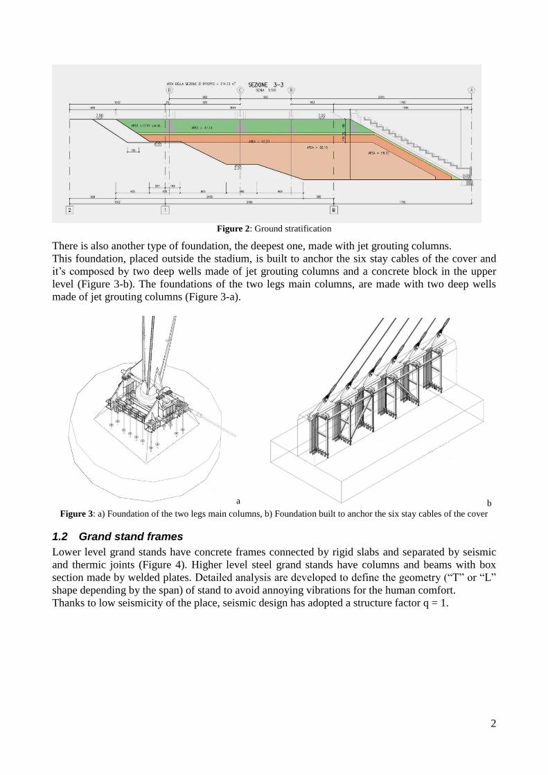
on ground stratification with different characteristics (Figure 2):
Layer D: is made up to 1.30 m below the foundation beams and must have a low ductility;
Layer B and C: respectively have a thickness of 0.30 m and 1,00 m. The level B have
stricter requirements regarding the size of materials.
Layer A: is the last one layer, where the flooring laying.
2
Figure 2: Ground stratification
There is also another type of foundation, the deepest one, made with jet grouting columns.
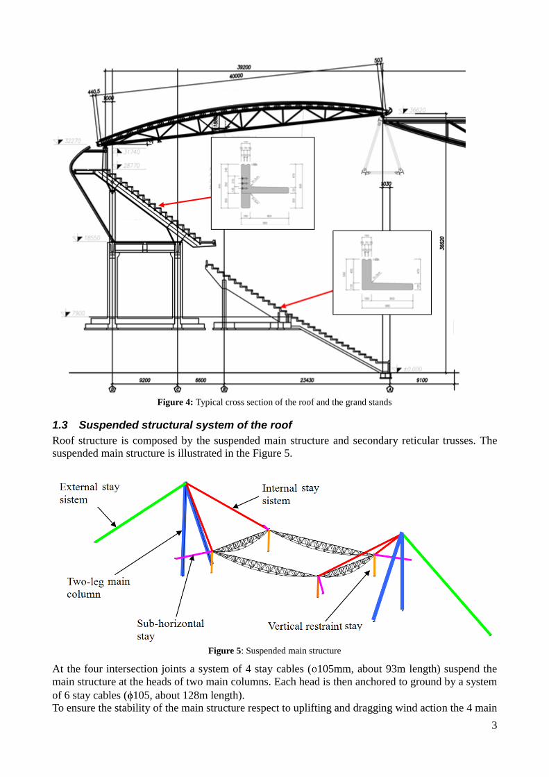
This foundation, placed outside the stadium, is built to anchor the six stay cables of the cover and
it’s composed by two deep wells made of jet grouting columns and a concrete block in the upper
level (Figure 3-b). The foundations of the two legs main columns, are made with two deep wells
made of jet grouting columns (Figure 3-a).
a b Figure 3: a) Foundation of the two legs main columns, b) Foundation built to anchor the six stay cables of the cover
1.2 Grand stand frames
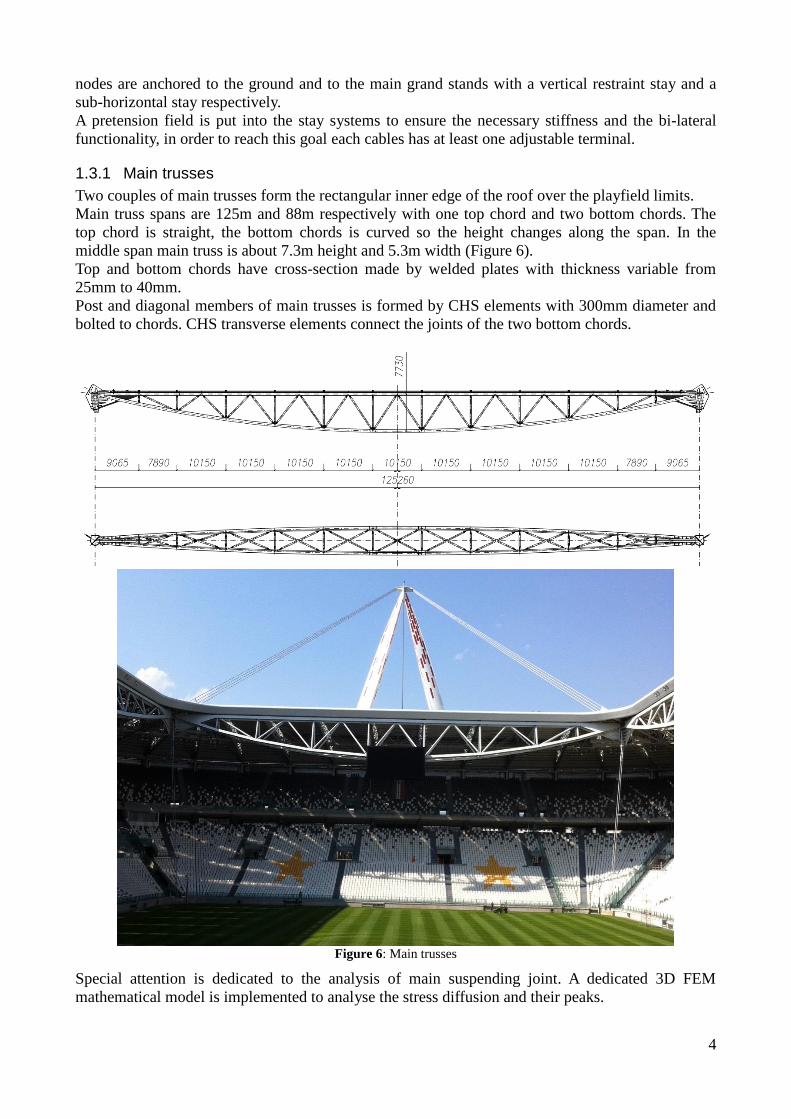
Lower level grand stands have concrete frames connected by rigid slabs and separated by seismic
and thermic joints (Figure 4). Higher level steel grand stands have columns and beams with box
section made by welded plates. Detailed analysis are developed to define the geometry (“T” or “L”
shape depending by the span) of stand to avoid annoying vibrations for the human comfort.
Thanks to low seismicity of the place, seismic design has adopted a structure factor q = 1.
3
Figure 4: Typical cross section of the roof and the grand stands
1.3 Suspended structural system of the roof
Roof structure is composed by the suspended main structure and secondary reticular trusses. The
suspended main structure is illustrated in the Figure 5.
Figure 5: Suspended main structure
At the four intersection joints a system of 4 stay cables ( 105mm, about 93m length) suspend the
main structure at the heads of two main columns. Each head is then anchored to ground by a system
of 6 stay cables ( 105, about 128m length).
To ensure the stability of the main structure respect to uplifting and dragging wind action the 4 main
4
nodes are anchored to the ground and to the main grand stands with a vertical restraint stay and a
sub-horizontal stay respectively.
A pretension field is put into the stay systems to ensure the necessary stiffness and the bi-lateral
functionality, in order to reach this goal each cables has at least one adjustable terminal.
1.3.1 Main trusses
Two couples of main trusses form the rectangular inner edge of the roof over the playfield limits.
Main truss spans are 125m and 88m respectively with one top chord and two bottom chords. The
top chord is straight, the bottom chords is curved so the height changes along the span. In the
middle span main truss is about 7.3m height and 5.3m width (Figure 6).
Top and bottom chords have cross-section made by welded plates with thickness variable from
25mm to 40mm.
Post and diagonal members of main trusses is formed by CHS elements with 300mm diameter and
bolted to chords. CHS transverse elements connect the joints of the two bottom chords.
Figure 6: Main trusses
Special attention is dedicated to the analysis of main suspending joint. A dedicated 3D FEM
mathematical model is implemented to analyse the stress diffusion and their peaks.

5
a b
Figure 7: a) Solid view drawing, b) 3D FEM mathematical model with graphic representation of stresses
1.3.2 Main columns
Main column has a “A” shape, formed by two legs 84m length and with a base of 45m. Each leg of
main column has tapered shape. Cross section shape is triangular formed by 3 curved plates
30/35mm thick. In the middle span the triangle side is about 3.75m length.
An internal system of transverse and longitudinal ribs stiffens the curved plates.
The head of main column has a main plate to connect the external stay system and a saddle to
deviate the cables of the internal stay system (Figure 8).
Figure 8: Head of the main column
Figure 9: Profile and section of the main column
The foot of each leg is designed as a spherical hinge with a forged steel sphere with 500mm radius.
6
Each main column is modelled as an element with variable cross section. It is subjected to its self-
weight, to axial force derived from main suspension system and to wind action.
The analysis of resistance and stability has followed these steps (according to EN1993-1-1):
1) determination of buckling factor of column;
2) determination of design imperfections and updating of mathematical model according this
deformed shape oriented such to have imperfection effects with same sign of external actions
effects;
3) analysis of response of the column to the design actions taking in account the geometric non-
linearity effects;
4) check cross sections resistance assuming Class 3 according EN1993-1-1;
5) design of longitudinal and transversal ribs according EN1993-1-5.
1.3.3 Secondary roof trusses
Along inner roof edge formed by main trusses and the outer edge formed by the top of the grand
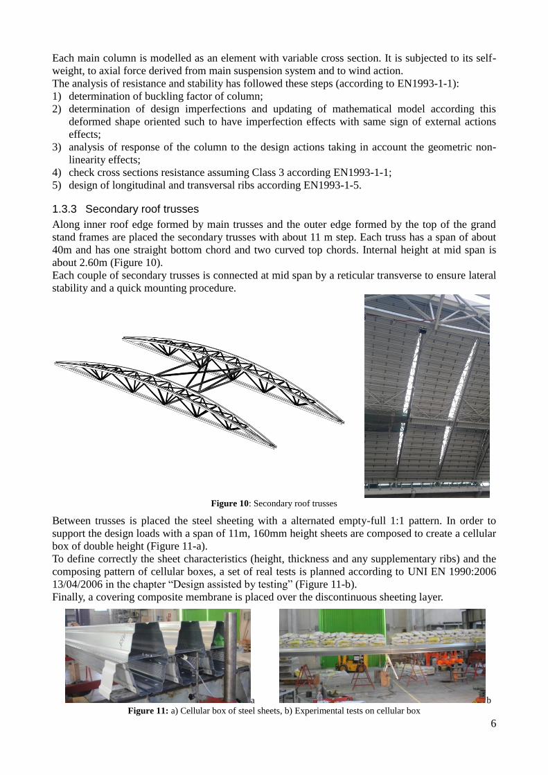
stand frames are placed the secondary trusses with about 11 m step. Each truss has a span of about
40m and has one straight bottom chord and two curved top chords. Internal height at mid span is
about 2.60m (Figure 10).
Each couple of secondary trusses is connected at mid span by a reticular transverse to ensure lateral
stability and a quick mounting procedure.
Figure 10: Secondary roof trusses
Between trusses is placed the steel sheeting with a alternated empty-full 1:1 pattern. In order to
support the design loads with a span of 11m, 160mm height sheets are composed to create a cellular
box of double height (Figure 11-a).
To define correctly the sheet characteristics (height, thickness and any supplementary ribs) and the
composing pattern of cellular boxes, a set of real tests is planned according to UNI EN 1990:2006
13/04/2006 in the chapter “Design assisted by testing” (Figure 11-b).
Finally, a covering composite membrane is placed over the discontinuous sheeting layer.
a b
Figure 11: a) Cellular box of steel sheets, b) Experimental tests on cellular box
7
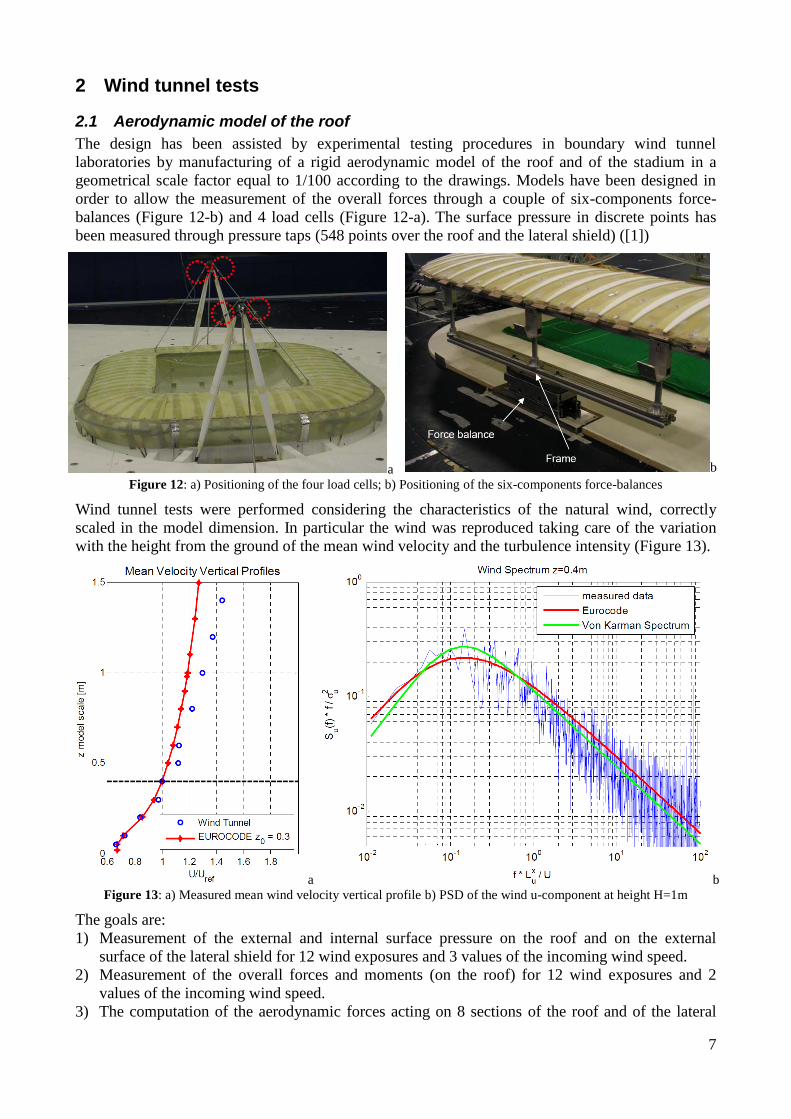
2 Wind tunnel tests
2.1 Aerodynamic model of the roof
The design has been assisted by experimental testing procedures in boundary wind tunnel
laboratories by manufacturing of a rigid aerodynamic model of the roof and of the stadium in a
geometrical scale factor equal to 1/100 according to the drawings. Models have been designed in
order to allow the measurement of the overall forces through a couple of six-components force-
balances (Figure 12-b) and 4 load cells (Figure 12-a). The surface pressure in discrete points has
been measured through pressure taps (548 points over the roof and the lateral shield) ([1])
a b
Figure 12: a) Positioning of the four load cells; b) Positioning of the six-components force-balances
Wind tunnel tests were performed considering the characteristics of the natural wind, correctly
scaled in the model dimension. In particular the wind was reproduced taking care of the variation
with the height from the ground of the mean wind velocity and the turbulence intensity (Figure 13).
a b Figure 13: a) Measured mean wind velocity vertical profile b) PSD of the wind u-component at height H=1m
The goals are:
1) Measurement of the external and internal surface pressure on the roof and on the external
surface of the lateral shield for 12 wind exposures and 3 values of the incoming wind speed.
2) Measurement of the overall forces and moments (on the roof) for 12 wind exposures and 2
values of the incoming wind speed.
3) The computation of the aerodynamic forces acting on 8 sections of the roof and of the lateral
8
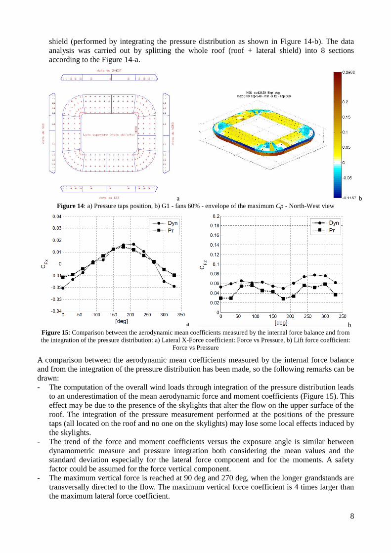
shield (performed by integrating the pressure distribution as shown in Figure 14-b). The data
analysis was carried out by splitting the whole roof (roof + lateral shield) into 8 sections
according to the Figure 14-a.
a b Figure 14: a) Pressure taps position, b) G1 - fans 60% - envelope of the maximum Cp - North-West view
a b
Figure 15: Comparison between the aerodynamic mean coefficients measured by the internal force balance and from
the integration of the pressure distribution: a) Lateral X-Force coefficient: Force vs Pressure, b) Lift force coefficient:
Force vs Pressure
A comparison between the aerodynamic mean coefficients measured by the internal force balance
and from the integration of the pressure distribution has been made, so the following remarks can be
drawn:
- The computation of the overall wind loads through integration of the pressure distribution leads
to an underestimation of the mean aerodynamic force and moment coefficients (Figure 15). This
effect may be due to the presence of the skylights that alter the flow on the upper surface of the
roof. The integration of the pressure measurement performed at the positions of the pressure
taps (all located on the roof and no one on the skylights) may lose some local effects induced by
the skylights.
- The trend of the force and moment coefficients versus the exposure angle is similar between
dynamometric measure and pressure integration both considering the mean values and the
standard deviation especially for the lateral force component and for the moments. A safety
factor could be assumed for the force vertical component.
- The maximum vertical force is reached at 90 deg and 270 deg, when the longer grandstands are
transversally directed to the flow. The maximum vertical force coefficient is 4 times larger than
the maximum lateral force coefficient.

9
- The fluctuation of the vertical force coefficient are 5 times larger than the lateral component
one.
- The fluctuation of the vertical force coefficient computed by integration of the pressure
distribution are larger and less exposure sensitive than the values measured by the
dynamometric system.
2.2 Aeroelastic model of a leg of the stadium towers
Another wind tunnel tests was carried out on an aeroelastic scaled model of a single leg of the
stadium towers. The aim of the tests in the wind tunnel on the aeroelastic model (Figure 16-a) was
to verify the possible vortex shedding phenomena related to a single tower leg for different wind
angles of attack (Figure 16-b).
a b
Figure 16: a) The aeroelastic model in the test section, b) Wind exposure angles
a b c Figure 17: a) Normalized displacement versus normalized mean wind speed (exposure 30°), b) Normalized
displacement versus normalized mean wind speed (exposure 75°), c) Normalized displacement versus normalized mean
wind speed (exposure 90°)
Results show that the most critical wind exposures angles are in the range of 45°-75°. Where the
normalized displacement amplitude reaches a value of about 0.06, which is about 0.25 m in full
scale displacement with an acceleration value of 14 m/s2. The test results also show that there is a
general similarity between the geometrically similar exposures. This means that the response results
for angles 45° and 75° are similar also angles 30° and 90° gives the same maximum displacement.
However the most sensitive exposures are angles 45° and 75°.
For each wind exposure angle the Strouhal number, lock-in velocity range, and the maximum
displacement amplitude of the center of the leg are summarized in Table 1.
Angle of attack [deg]
St Lock-in range (U/Ust)
Maximum displacement (x/D)
15 - - <0.0080
30 0.21 0.9831 - 1.0186 0.0080
45 0.137 0.8669 - 1.1771 0.0586

10
60 0.13 0.9385 - 1.0746 0.0493
75 0.135 0.8333 - 1.2530 0.0569
90 0.17 0.9563 - 1.0471 0.008
105 0.22 0.9972 - 1.0148 0.0059
120 0.22 0.9829 - 1.0171 0.0040 Table 1
3 Installation procedure, materials and list of the steel quantities
3.1 Installation procedure
The main trusses and the main columns have been assembled on the ground after the demolition of
the existing structure and the construction of the new grand stands.
The 5 blocks forming the main columns have been built in the workshop and have been assembled
near the north and south bases (Figure 18-b).
The four main trusses were assembled in blocks (Figure 18-a) of the maximum length of 17 m into
the playground using provisional supports at the height of the first level of the main stands.
a b Figure 18: a) A block of the main trusses in the workshop b) Assembling of the main column
a b Figure 19: Lifting of the main trusses
Simultaneously with the assembling of the main trusses and the main columns on the ground, a
provisional tower (realized with a lattice structure) has been built using a crane and a telescopic
platform operating in the middle of playing field.
Completed the installation of the provisional tower the jacks (with a capacity of 9000 KN) have
been placed to connect the top of the main columns with the top of the provisional tower and to
connect the top of the main columns with the anchor block of the stay cables.
Finally the roof structure has been lifted following the steps below:
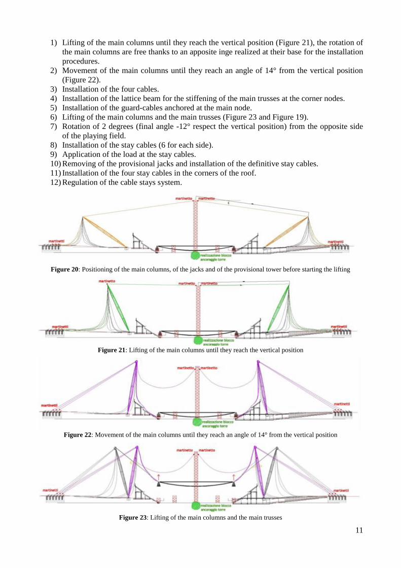
11
1) Lifting of the main columns until they reach the vertical position (Figure 21), the rotation of
the main columns are free thanks to an apposite inge realized at their base for the installation
procedures.
2) Movement of the main columns until they reach an angle of 14° from the vertical position
(Figure 22).
3) Installation of the four cables.
4) Installation of the lattice beam for the stiffening of the main trusses at the corner nodes.
5) Installation of the guard-cables anchored at the main node.
6) Lifting of the main columns and the main trusses (Figure 23 and Figure 19).
7) Rotation of 2 degrees (final angle -12° respect the vertical position) from the opposite side
of the playing field.
8) Installation of the stay cables (6 for each side).
9) Application of the load at the stay cables.
10) Removing of the provisional jacks and installation of the definitive stay cables.
11) Installation of the four stay cables in the corners of the roof.
12) Regulation of the cable stays system.
Figure 20: Positioning of the main columns, of the jacks and of the provisional tower before starting the lifting
Figure 21: Lifting of the main columns until they reach the vertical position
Figure 22: Movement of the main columns until they reach an angle of 14° from the vertical position
Figure 23: Lifting of the main columns and the main trusses

12
After the lifting of the main structural system the secondary beams have been installed with the
steel sheeting already applied (Figure 24). Then over the structure have been placed a covering
composite membrane and the lighting devices.
Figure 24: Installation of secondary beams
3.2 Materials
Structural steel second EN 10025:
Fe 510 (S355) with characteristic yield stress fyk 355 N/mm²
Fe 430 (S275) with characteristic yield stress fyk 275 N/mm²
S460 with characteristic yield stress fyk 460 N/mm²
Stell for the cables:
Nominal failure strength = 1570 MPa min.
Proof stress Rp0,2 = 1180 MPa min.
Elongation to failure: 4% min.
Young Module E = 163000 MPa
3.3 List of the steel quantities
The following table shows the weight of the steel structural elements of the roof:
Weight [kg]
Main trusses 1'306'743
Main Columns 1'315'217
Secondary standard beams (n° 52) 919'360
Bracing system 75'712
Roof catwalks 258'840
Internal gutters 121'399
External gutters 140'826
Secondary corner beams (n° 8) 160'576
Secondary support corner beams 98'400
Internal catwalk 190'871
Hi-bond sheet 449'280
Omega profiles 43'296
4 References [1] DIANA. G.., RESTA F. - Politecnico di Milano – Dipartimento di Meccanica. “Svolgimento
di prove in galleria del vento: progetto del nuovo Stadio Juventus”, 02/02/2008.
[2] DIANA. G.., RESTA F. - Politecnico di Milano – Dipartimento di Meccanica. “Aeroelastic behaviour of the stadium tower leg”, 08/06/2009.
[3] M. Majowiecki, F. Ossola, S. Pinardi – Il Sistema Strutturale del Nuovo Stadio della Juventus, Costruzioni Metalliche, n°4, Ottobre 2011.